WO2016110938A1 - 半田ボールフィーダ - Google Patents
半田ボールフィーダ Download PDFInfo
- Publication number
- WO2016110938A1 WO2016110938A1 PCT/JP2015/050064 JP2015050064W WO2016110938A1 WO 2016110938 A1 WO2016110938 A1 WO 2016110938A1 JP 2015050064 W JP2015050064 W JP 2015050064W WO 2016110938 A1 WO2016110938 A1 WO 2016110938A1
- Authority
- WO
- WIPO (PCT)
- Prior art keywords
- ball
- solder
- feeder
- squeegee
- solder ball
- Prior art date
- Legal status (The legal status is an assumption and is not a legal conclusion. Google has not performed a legal analysis and makes no representation as to the accuracy of the status listed.)
- Ceased
Links
Images




Classifications
-
- H—ELECTRICITY
- H05—ELECTRIC TECHNIQUES NOT OTHERWISE PROVIDED FOR
- H05K—PRINTED CIRCUITS; CASINGS OR CONSTRUCTIONAL DETAILS OF ELECTRIC APPARATUS; MANUFACTURE OF ASSEMBLAGES OF ELECTRICAL COMPONENTS
- H05K3/00—Apparatus or processes for manufacturing printed circuits
- H05K3/30—Assembling printed circuits with electric components, e.g. with resistors
- H05K3/32—Assembling printed circuits with electric components, e.g. with resistors electrically connecting electric components or wires to printed circuits
- H05K3/34—Assembling printed circuits with electric components, e.g. with resistors electrically connecting electric components or wires to printed circuits by soldering
-
- H—ELECTRICITY
- H05—ELECTRIC TECHNIQUES NOT OTHERWISE PROVIDED FOR
- H05K—PRINTED CIRCUITS; CASINGS OR CONSTRUCTIONAL DETAILS OF ELECTRIC APPARATUS; MANUFACTURE OF ASSEMBLAGES OF ELECTRICAL COMPONENTS
- H05K13/00—Apparatus or processes specially adapted for manufacturing or adjusting assemblages of electric components
- H05K13/02—Feeding of components
Definitions
- the present invention relates to a solder ball feeder for supplying solder balls to a component mounting machine.
- a solder ball feeder for supplying a solder ball to a component mounting machine includes a squeegee in which a space for accommodating a solder ball is formed and a solder ball as described in Patent Document 1 (Japanese Patent Laid-Open No. 2011-91192).
- a ball alignment plate in which a predetermined number of ball holes to be accommodated one by one are formed in a predetermined arrangement pattern, and the ball alignment plate or squeegee is slid in a state where the lower end of the squeegee is in close contact with or close to the upper surface of the ball alignment plate
- a squeegeeing operation is performed in which the solder balls in the squeegee enter the respective ball holes of the ball alignment plate from the lower end opening of the squeegee.
- the operator can manually move the squeegee and ball alignment plate, so the operator may manually move the squeegee when changing the setup.
- the squeegee if there is a ball alignment plate below the squeegee, the lower end opening of the squeegee is closed by the ball alignment plate, so that the solder balls in the squeegee do not fall down.
- the problem to be solved by the present invention is to make it possible to easily collect the solder balls that have fallen into the solder ball feeder from the lower end opening of the squeegee.
- the present invention provides a ball alignment in which a squeegee in which a space for accommodating a large number of solder balls is formed and a predetermined number of ball holes each for receiving one solder ball are formed in a predetermined array pattern.
- the solder ball in the squeegee is moved from the lower end opening of the squeegee by sliding the squeegee or the ball alignment plate with the plate and the lower end of the squeegee in close contact with or close to the upper surface of the ball alignment plate.
- the falling ball collection for collecting the solder ball that has fallen into the solder ball feeder from the lower end opening of the squeegee It is set as the structure provided with the means. In this configuration, even when a large number of solder balls in the squeegee spill into the solder ball feeder from the lower end opening of the squeegee, the solder balls that have fallen into the solder ball feeder can be recovered by the falling ball recovery means. Therefore, it is possible to easily collect the solder balls that have fallen down.
- the present invention provides a falling ball collecting case in which a falling ball collecting means is detachably attached to a solder ball feeder, and a drop for rolling a solder ball that has fallen into the inside of the solder ball feeder into the falling ball collecting case. It may be composed of a ball collecting slope. In this way, the solder balls that have fallen into the inside of the solder ball feeder roll around the falling ball collecting slope and are collected in the falling ball collection case. Therefore, the solder balls that have fallen into the inside of the solder ball feeder Can be recovered very simply by detaching the falling ball recovery case.
- the falling ball collection case may be attached so as to be detachable by engaging means and / or screws.
- the falling ball collecting slope may be arranged so as to cover an area in the solder ball feeder where the solder balls may fall.
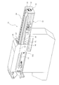
- FIG. 1 is a perspective view of a solder ball feeder according to an embodiment of the present invention.
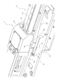
- FIG. 2 is a perspective view of the solder ball feeder with some side plates removed.
- FIG. 3 is a perspective view of the main part of the solder ball feeder for explaining the method for attaching and detaching the falling ball collection case.
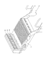
- FIG. 4 is a perspective view of the falling ball collection case.
- FIG. 5 is a perspective view of the main part of the solder ball feeder showing a state where both the squeegee and the ball alignment plate are at the origin position (a state where the solder balls in the squeegee do not fall down).
- FIG. 6 is a perspective view of the main part of the solder ball feeder showing a state where the ball alignment plate is not present below the squeegee (a state where the solder balls in the squeegee fall down).
- FIG. 7 is a plan view of the ball alignment plate.
- FIG. 8 is a perspective view of a feeder set base of the component mounter.
- FIG. 9 is a block diagram showing the configuration of the control system of the component mounter.
- the solder ball feeder 11 is set on a feeder set base 12 (see FIG. 8) of a component mounting machine (not shown) so as to be replaceable with a tape feeder (not shown).
- the width dimension of the solder ball feeder 11 is substantially several times the width dimension of the tape feeder, and the solder ball feeder 11 is detachably set in a space corresponding to several tape feeders on the feeder set base 12.
- a box-shaped feeder main body 13 that extends in the front-rear direction, which is an attaching / detaching direction to the feeder set base 12 of the component mounting machine (see FIG. 8), is provided on the upper portion of the solder ball feeder 11.
- a guide rail 14 is provided on the feeder main body 13 so as to extend in the front-rear direction.
- a slide base 15 is supported on the guide rail 14 so as to be slidable in the front-rear direction, and a ball alignment plate 16 is sandwiched by a U-shaped fixed frame 17 on the slide base 15 and screw 18. It is detachably attached.
- the ball alignment plate 16 has a predetermined number of ball holes 21 for receiving one solder ball in a predetermined arrangement pattern.
- two position correction marks 22 are formed at predetermined positions on the front side of the upper surface of the ball alignment plate 16 where the ball holes 21 are not formed (the mounting direction side of the solder ball feeder 11).
- the position correction mark 22 is imaged with a mark imaging camera 23 (see FIG. 9) provided in the component mounter and is recognized, so that the position correction mark 22 is used as a reference.
- the mark imaging camera 23 is provided so as to move integrally with the mounting head (not shown) by the head moving device 24 of the component mounting machine.
- the mark imaging camera 23 uses the reference of the circuit board on the conveyor 30. By imaging the mark and recognizing the reference mark, the component mounting position of the circuit board is corrected based on the position of the reference mark.
- a squeegee 27 formed with a space for accommodating a large number of solder balls is slidable in the front-rear direction on the rear side of the feeder main body 13 (the removal direction side of the solder ball feeder 11).
- the height position of the squeegee 27 is set so that the lower end of the squeegee 27 is in close contact with or close to the upper surface of the ball alignment plate 16. It has been adjusted.
- a squeegee drive mechanism 28 for sliding the squeegee 27 in the front-rear direction is provided in the feeder main body 13, and the ball alignment plate 16 is the origin shown in FIG. 2 regardless of automatic operation / manual operation when the solder ball feeder 11 is energized. Only when it is in the position, the squeegee 27 is interlocked so that it can be slid forward by the squeegee drive mechanism 28 (see FIG. 9). With the ball alignment plate 16 stopped at the origin position shown in FIG. 5, the lower end of the squeegee 27 is brought into close contact with or close to the upper surface of the ball alignment plate 16, and the squeegee 27 is moved by the squeegee driving mechanism 28.
- the squeegee performs a squeegeeing operation to cause the solder balls in the squeegee 27 to enter the ball holes 21 of the ball alignment plate 16 from the lower end opening of the squeegee 27 by sliding forward along the upper surface of the ball.
- a predetermined number of solder balls are arranged in a predetermined arrangement pattern on the alignment plate 16.
- the solder ball in the squeegee 27 is moved from the lower end opening of the squeegee 27 by sliding the ball alignment plate 16 in a state where the lower end of the squeegee 27 is in close contact with or close to the upper surface of the ball alignment plate 16. You may make it enter in each ball hole 21 of the alignment plate 16.
- a ball alignment plate driving mechanism 29 driving means for sliding and moving the ball alignment plate 16 (slide base 15) in the front-rear direction is provided, and the ball alignment plate 16 is moved by the ball alignment plate driving mechanism 29. Is slid between the origin position shown in FIG. 5 and the solder ball suction position on the front end side of the feeder main body 13. After the squeegee 27 is slid forward along the upper surface of the ball alignment plate 16 at the origin position shown in FIG.
- the solder balls are accommodated in the ball holes 21 of the ball alignment plate 16, and then the ball alignment plate 16 is slid and moved to the solder ball suction position on the front end side of the feeder main body 13, and the solder balls in the ball holes 21 of the ball alignment plate 16 are sequentially sucked by the suction nozzle of the component mounting machine, and the circuit on the conveyor 30 is sucked. It is designed to be mounted on the board.
- the signal line and the power line of the solder ball feeder 11 are connected to the front end surface (end surface on the attachment direction side) of the feeder main body 13 with the connector 31 (see FIG. 8) and two positioning pins 33, 34 are provided, and the two positioning pins 33, 34 are provided with positioning holes 35, 36 (see FIG. 8) of the feeder set base 12 of the component mounting machine. 2), the mounting position of the solder ball feeder 11 is positioned on the feeder set base 12, and the connector 32 of the solder ball feeder 11 is inserted and connected to the connector 31 of the feeder set base 12. Yes.
- the control device 41 of the component mounting machine includes an input device 42 such as a keyboard, a mouse, and a touch panel, and a storage device 43 (memory) such as a hard disk, RAM, and ROM that stores various control programs and data. Means) and a display device 44 such as a liquid crystal display and a CRT.
- the component mounter is provided with a part imaging camera 45 for imaging a component such as a solder ball adsorbed by an adsorption nozzle (not shown) from below.
- the operator can move the squeegee 27 and the ball alignment plate 16 manually. Therefore, the operator manually moves the squeegee 27 from the origin position when changing the setup. However, if the ball alignment plate 16 exists below the squeegee 27 when the operator manually moves the squeegee 27, the lower end opening of the squeegee 27 is closed by the ball alignment plate 16, The solder balls in the squeegee 27 do not fall down. However, when the operator manually moves the squeegee 27, as shown in FIG.
- the solder ball feeder 11 of this embodiment has a configuration including a falling ball collecting means 51 that collects the solder balls that have fallen into the solder ball feeder 11 from the lower end opening of the squeegee 27.
- a falling ball collecting means 51 that collects the solder balls that have fallen into the solder ball feeder 11 from the lower end opening of the squeegee 27.
- the falling ball collecting means 51 is directed to the falling ball collecting case 52 detachably attached to the vicinity of the center of the solder ball feeder 11 and the solder ball spilled into the solder ball feeder 11 toward the falling ball collecting case 52. And a falling ball collecting slope 53 that rolls.
- the falling ball collecting slope 53 is formed in a bowl shape inclined downward toward the falling ball collection case 52 located near the center of the solder ball feeder 11, and there is a possibility that the solder balls inside the solder ball feeder 11 fall down. It is attached by screws or the like so as to cover a certain area.
- the falling ball collecting slope 53 does not need to be configured to be removable, but it goes without saying that it may be configured to be removable for the convenience of cleaning and the like.
- a mounting opening 54 for mounting the falling ball collection case 52 is formed.
- the side plate 52a of the falling ball collection case 52 is sized to close the mounting opening 54 of the side plate 13a of the feeder body 13, and is provided at two locations on the lower edge of the side plate 52a.
- An engagement piece 55 (engagement means) is formed downward, and a screw insertion hole 56 is formed at the center of the upper edge of the side plate 52a.
- the falling ball collecting case 52 is inserted into the engaging hole 55 (not shown) at the lower edge of the attachment opening 54 on the feeder body 13 side by inserting the engaging piece 55 at the lower edge of the side plate 52a of the falling ball collecting case 52.
- a screw 57 (see FIGS. 1 and 2) is inserted into the screw insertion hole 56 at the upper edge of the side plate 52a, and the screw 57 is inserted into the screw hole 58 at the upper edge of the attachment opening 54 on the feeder body 13 side.
- the fall ball collection case 52 is detachably attached to the feeder main body 13 by tightening to (see FIG. 3).
- the side plate 52a of the falling ball collection case 52 closes the attachment opening 54 on the feeder main body 13 side, and the lowest opening of the falling ball collection slope 53 is the falling ball. Solder balls that face the collection case 52 and roll over the fall ball collection case 52 fall into the fall ball collection case 52 from the lowest opening of the fall ball collection slope 53 and are collected.
- the operator can remove the falling ball collection case 52 simply by removing the screw 57 that fixes the falling ball collection case 52.
- the engagement piece 55 of the falling ball collection case 52 becomes the lower edge of the attachment opening 54 on the feeder body 13 side.
- the falling ball recovery case 52 is removed from the solder ball feeder 11. After the solder balls accumulated in the falling ball collection case 52 are returned into the squeegee 27, if the falling ball collection case 52 is attached to the attachment opening 54 on the feeder body 13 side, the solder balls fall into the solder ball feeder 11. The solder ball collection operation is completed.
- the solder ball feeder 11 of the present embodiment described above includes the falling ball collecting means 51 for collecting the solder balls that have fallen into the solder ball feeder 11 from the lower end opening of the squeegee 27, a large number of squeegees 27 have a large number of them. Even when the solder balls fall down from the lower end opening of the squeegee 27 into the solder ball feeder 11, the solder balls that have fallen down into the solder ball feeder 11 can be collected by the fall ball collecting means 51. It is possible to easily collect the solder balls.
- the falling ball collecting means 51 includes a falling ball collecting case 52 that is detachably attached to the solder ball feeder 11, and a solder ball that has fallen into the inside of the solder ball feeder 11. Since the falling ball collecting slope 53 rolls toward the inside of the solder ball 52, the solder ball falling into the solder ball feeder 11 can be collected in the falling ball collecting case 52 by rolling the falling ball collecting slope 53. The solder balls that have fallen into the solder ball feeder 11 can be recovered very simply by simply attaching and detaching the falling ball recovery case 52.
- the present invention is not limited to the above configuration, and the configuration of the falling ball collecting means 51 may be changed as appropriate.
- the falling ball collecting means 51 is engaged with the attachment opening 54 on the feeder body 13 side.
- the falling ball collecting case 52 and the falling ball collecting slope 53 may be integrated, and both may be integrally attached and detached.
- the configuration may be such that the solder balls collected in the falling ball collection case 52 are collected while the falling ball collection case 52 is attached to the solder ball feeder 11, and in this case, an opening is formed at the bottom of the falling ball collection case 52.
- a shutter mechanism for opening and closing the opening is provided, and when collecting the solder balls accumulated in the falling ball collection case 52, the operator can use the shutter mechanism without removing the falling ball collection case 52.
- An appropriate case prepared by the operator from the opening at the bottom of the falling ball collection case 52 by operating to open the opening at the bottom of the falling ball collection case 52 and collecting the solder balls accumulated in the falling ball collection case 52 You may make it fall and collect
Landscapes
- Engineering & Computer Science (AREA)
- Manufacturing & Machinery (AREA)
- Microelectronics & Electronic Packaging (AREA)
- Electric Connection Of Electric Components To Printed Circuits (AREA)
Abstract
半田ボールフィーダ(11)は、スキージ(27)の下端開口から半田ボールフィーダ(11)の内部に零れ落ちた半田ボールを回収する落下ボール回収手段(51)を備える。落下ボール回収手段(51)は、半田ボールフィーダ(11)の中央付近に脱着可能に取り付けられた落下ボール回収ケース(52)と、該半田ボールフィーダ(11)の内部に零れ落ちた半田ボールを落下ボール回収ケース(52)内へ向かって転がす落下ボール収集スロープ(53)とから構成されている。この構成では、スキージ(27)内の多数の半田ボールがスキージ(27)の下端開口から半田ボールフィーダ(11)の内部に零れ落ちた場合でも、半田ボールフィーダ(11)の内部に零れ落ちた半田ボールを落下ボール回収手段(51)によって簡単に回収することができる。
Description
本発明は、部品実装機に半田ボールを供給する半田ボールフィーダに関する発明である。
部品実装機に半田ボールを供給する半田ボールフィーダは、特許文献1(特開2011-91192号公報)に記載されているように、半田ボールを収容するスペースが形成されたスキージと、半田ボールを1個ずつ収める所定数のボール穴が所定の配列パターンで形成されたボール整列板とを備え、スキージの下端をボール整列板の上面に密着又は近接させた状態でボール整列板又はスキージをスライド移動させることで、スキージ内の半田ボールを該スキージの下端開口からボール整列板の各ボール穴内に入り込ませるスキージング動作を実行するようにしたものがある。
ところで、半田ボールフィーダの電源オフ時には、作業者がスキージやボール整列板を手動で移動できる状態になるため、段取替え時等に作業者が手動でスキージを移動させてしまうことがあるが、作業者が手動でスキージを移動させたときに、そのスキージの下方にボール整列板が存在すれば、スキージの下端開口がボール整列板で閉鎖されて、スキージ内の半田ボールが零れ落ちることはない。しかし、作業者が手動でスキージを移動させたときに、スキージの下方にボール整列板が存在しなければ、スキージの下端開口が開放されて、スキージ内に溜まった多数の半田ボールがスキージの下端開口から零れ落ちて半田ボールフィーダの内部に広範囲に散乱してしまう。この場合は、半田ボールフィーダの内部に広範囲に散乱した多数の半田ボールを回収する手間のかかる作業を作業者が行わなければならず、非常に面倒であるばかりか、半田ボールの回収作業に時間がかかって生産開始が遅れるという欠点があった。
そこで、本発明が解決しようとする課題は、スキージの下端開口から半田ボールフィーダの内部に零れ落ちた半田ボールを簡単に回収できるようにすることでである。
上記課題を解決するために、本発明は、多数の半田ボールを収容するスペースが形成されたスキージと、半田ボールを1個ずつ収める所定数のボール穴が所定の配列パターンで形成されたボール整列板と、前記スキージの下端を前記ボール整列板の上面に密着又は近接させた状態で該スキージ又は該ボール整列板をスライド移動させることで該スキージ内の半田ボールを該スキージの下端開口から該ボール整列板の各ボール穴内に入り込ませるスキージング動作を実行する駆動手段とを備えた半田ボールフィーダにおいて、前記スキージの下端開口から該半田ボールフィーダの内部に零れ落ちた半田ボールを回収する落下ボール回収手段を備えた構成としたものである。この構成では、スキージ内の多数の半田ボールがスキージの下端開口から半田ボールフィーダの内部に零れ落ちた場合でも、半田ボールフィーダの内部に零れ落ちた半田ボールを落下ボール回収手段によって回収することができるため、零れ落ちた半田ボールの回収作業を簡単に行うことができる。
本発明は、落下ボール回収手段を、半田ボールフィーダに脱着可能に取り付けられた落下ボール回収ケースと、該半田ボールフィーダの内部に零れ落ちた半田ボールを前記落下ボール回収ケース内へ向かって転がす落下ボール収集スロープとから構成すると良い。このようにすれば、半田ボールフィーダの内部に零れ落ちた半田ボールが落下ボール収集スロープを転がって落下ボール回収ケース内に収集されるようになるため、半田ボールフィーダの内部に零れ落ちた半田ボールを落下ボール回収ケースの脱着のみで極めて簡単に回収することができる。
この場合、落下ボール回収ケースは、係合手段及び/又はねじにより脱着可能に取り付けるようにすれば良い。
また、落下ボール収集スロープは、半田ボールフィーダの内部のうちの半田ボールが零れ落ちる可能性のある領域をカバーするように配置すれば良い。
以下、本発明を実施するための形態を具体化した一実施例を図面を用いて説明する。
まず、半田ボールフィーダ11の構成を説明する。
半田ボールフィーダ11は、部品実装機(図示せず)のフィーダセット台12(図8参照)にテープフィーダ(図示せず)と付け替え可能にセットされる。半田ボールフィーダ11の横幅寸法は、テープフィーダの横幅寸法のほぼ数倍となっており、フィーダセット台12上のテープフィーダ数台分のスペースに半田ボールフィーダ11が着脱可能にセットされる。
半田ボールフィーダ11は、部品実装機(図示せず)のフィーダセット台12(図8参照)にテープフィーダ(図示せず)と付け替え可能にセットされる。半田ボールフィーダ11の横幅寸法は、テープフィーダの横幅寸法のほぼ数倍となっており、フィーダセット台12上のテープフィーダ数台分のスペースに半田ボールフィーダ11が着脱可能にセットされる。
図1及び図2に示すように、半田ボールフィーダ11の上部には、部品実装機のフィーダセット台12(図8参照)への着脱方向である前後方向に長く延びる箱状のフィーダ本体13が設けられ、該フィーダ本体13上にガイドレール14が前後方向に延びるように設けられている。図5に示すように、ガイドレール14上にスライドベース15が前後方向にスライド移動可能に支持され、該スライドベース15上にボール整列板16がコ字形の固定枠17で挟み付けられてねじ18で着脱可能に取り付けられている。
図7に示すように、ボール整列板16には、半田ボールを1個ずつ収める所定数のボール穴21が所定の配列パターンで形成されている。ボール整列板16の上面のうちのボール穴21が形成されていない前方側(半田ボールフィーダ11の取り付け方向側)の周辺部分の所定位置には、例えば2個の位置補正マーク22が形成され、該位置補正マーク22を、部品実装機に装備されたマーク撮像用のカメラ23(図9参照)で撮像して該位置補正マーク22を認識することで、該位置補正マーク22の位置を基準にしてボール整列板16の各ボール穴21の位置を補正するようにしている。マーク撮像用のカメラ23は、部品実装機のヘッド移動装置24によって実装ヘッド(図示せず)と一体的に移動するように設けられ、マーク撮像用のカメラ23でコンベア30上の回路基板の基準マークを撮像して該基準マークを認識することで、該基準マークの位置を基準にして回路基板の部品実装位置を補正するようにしている。
図5及び図6に示すように、フィーダ本体13の後方側(半田ボールフィーダ11の取り外し方向側)には、多数の半田ボールを収容するスペースが形成されたスキージ27が前後方向にスライド移動可能に設けられ、このスキージ27がボール整列板16の上面に沿ってスライド移動する際に、該スキージ27の下端がボール整列板16の上面に密着又は近接するように該スキージ27の高さ位置が調整されている。
フィーダ本体13内には、スキージ27を前後方向にスライド移動させるスキージ駆動機構28が設けられ、半田ボールフィーダ11の通電時に自動運転/マニュアル運転に関わらず、ボール整列板16が図2に示す原点位置にあるときのみスキージ27がスキージ駆動機構28(図9参照)によって前方にスライド移動可能となるようにインターロックが掛かっている。ボール整列板16が図5に示す原点位置で停止している状態で、スキージ27の下端をボール整列板16の上面に密着又は近接させて、該スキージ27をスキージ駆動機構28によってボール整列板16の上面に沿って前方にスライド移動させることで該スキージ27内の半田ボールを該スキージ27の下端開口から該ボール整列板16の各ボール穴21内に入り込ませるスキージング動作を実行して該ボール整列板16に所定数の半田ボールを所定の配列パターンで配列するようにしている。尚、スキージ27の下端をボール整列板16の上面に密着又は近接させた状態で、該ボール整列板16をスライド移動させることで該スキージ27内の半田ボールを該スキージ27の下端開口から該ボール整列板16の各ボール穴21内に入り込ませるようにしても良い。
フィーダ本体13内には、ボール整列板16(スライドベース15)を前後方向にスライド移動させるボール整列板駆動機構29(駆動手段)が設けられ、該ボール整列板駆動機構29によって該ボール整列板16を図5に示す原点位置とフィーダ本体13の前端側の半田ボール吸着位置との間をスライド移動させるようになっている。図5に示す原点位置にあるボール整列板16の上面に沿ってスキージ27を前方にスライド移動させることで該ボール整列板16の各ボール穴21内に半田ボールを収容した後、該ボール整列板16をフィーダ本体13の前端側の半田ボール吸着位置へスライド移動させて、部品実装機の吸着ノズルでボール整列板16の各ボール穴21内の半田ボールを順番に吸着してコンベア30上の回路基板に実装するようにしている。
図1及び図2に示すように、フィーダ本体13の前端面(取り付け方向側の端面)には、半田ボールフィーダ11の信号線や電源線を部品実装機のフィーダセット台12のコネクタ31(図8参照)に接続するためのコネクタ32と、2本の位置決めピン33,34が設けられ、2本の位置決めピン33,34を部品実装機のフィーダセット台12の位置決め穴35,36(図8参照)に差し込むことで、フィーダセット台12上で半田ボールフィーダ11の取付位置が位置決めされると共に、半田ボールフィーダ11のコネクタ32がフィーダセット台12のコネクタ31に差し込み接続されるようになっている。
図9に示すように、部品実装機の制御装置41には、キーボード、マウス、タッチパネル等の入力装置42と、各種制御プログラムやデータ等を記憶するハードディスク、RAM、ROM等の記憶装置43(記憶手段)と、液晶ディスプレイ、CRT等の表示装置44等が接続されている。その他、部品実装機には、吸着ノズル(図示せず)に吸着した半田ボール等の部品をその下方から撮像するパーツ撮像用のカメラ45等が設けられている。
ところで、半田ボールフィーダ11の電源オフ時には、作業者がスキージ27やボール整列板16を手動で移動できる状態になるため、段取替え時等に作業者が手動でスキージ27を原点位置から移動させてしまうことがあるが、作業者が手動でスキージ27を移動させたときに、そのスキージ27の下方にボール整列板16が存在すれば、スキージ27の下端開口がボール整列板16で閉鎖されて、スキージ27内の半田ボールが零れ落ちることはない。しかし、作業者が手動でスキージ27を移動させたときに、図6に示すように、スキージ27の下方にボール整列板16が存在しなければ、スキージ27の下端開口が開放されて、スキージ27内に溜まった多数の半田ボールがスキージ27の下端開口から零れ落ちて半田ボールフィーダ11の内部に広範囲に散乱してしまうため、半田ボールフィーダ11の内部に零れ落ちた半田ボールを回収する必要がある。
そこで、本実施例の半田ボールフィーダ11は、スキージ27の下端開口から半田ボールフィーダ11の内部に零れ落ちた半田ボールを回収する落下ボール回収手段51を備えた構成となっている。以下、落下ボール回収手段51の構成を図1乃至図4を用いて説明する。
落下ボール回収手段51は、半田ボールフィーダ11の中央付近に脱着可能に取り付けられた落下ボール回収ケース52と、該半田ボールフィーダ11の内部に零れ落ちた半田ボールを落下ボール回収ケース52内へ向かって転がす落下ボール収集スロープ53とから構成されている。落下ボール収集スロープ53は、半田ボールフィーダ11の中央付近に位置する落下ボール回収ケース52に向かって下り傾斜する樋状に形成され、半田ボールフィーダ11の内部のうちの半田ボールが零れ落ちる可能性のある領域をカバーするようにねじ止め等により取り付けられている。尚、落下ボール収集スロープ53は、脱着可能に構成する必要はないが、掃除等の便宜のために脱着可能に構成しても良いことは言うまでもない。
フィーダ本体13の側板13aの中央付近には、落下ボール回収ケース52を取り付けるための取付用開口部54(図1参照)が形成されている。図3及び図4に示すように、落下ボール回収ケース52の側板52aは、フィーダ本体13の側板13aの取付用開口部54を塞ぐ大きさに形成され、該側板52aの下縁部の2箇所に係合片55(係合手段)が下向きに形成され、該側板52aの上縁部の中央部にねじ挿通孔56が形成されている。落下ボール回収ケース52の側板52aの下縁部の係合片55をフィーダ本体13側の取付用開口部54の下縁部の係合孔(図示せず)に差し込んで、落下ボール回収ケース52の側板52aの上縁部のねじ挿通孔56にねじ57(図1及び図2参照)を挿通して、該ねじ57をフィーダ本体13側の取付用開口部54の上縁部のねじ孔58(図3参照)に締め付けることで、落下ボール回収ケース52をフィーダ本体13に脱着可能に取り付けるようにしている。落下ボール回収ケース52をフィーダ本体13に取り付けた状態では、落下ボール回収ケース52の側板52aでフィーダ本体13側の取付用開口部54を塞ぐと共に、落下ボール収集スロープ53の最低部開口が落下ボール回収ケース52内に臨み、落下ボール回収ケース52を転がる半田ボールが該落下ボール収集スロープ53の最低部開口から落下ボール回収ケース52内に落下して収集されるようになっている。
落下ボール回収ケース52内に収集された半田ボールを回収する場合は、作業者は、落下ボール回収ケース52を固定したねじ57を取り外すだけで、落下ボール回収ケース52が取り外し可能な状態となる。この状態で、図3に示すように、落下ボール回収ケース52を手前に傾けて持ち上げれば、落下ボール回収ケース52の係合片55がフィーダ本体13側の取付用開口部54の下縁部の係合孔から抜き出されて、落下ボール回収ケース52が半田ボールフィーダ11から取り外された状態となる。落下ボール回収ケース52内に溜まった半田ボールをスキージ27内に戻した後、落下ボール回収ケース52をフィーダ本体13側の取付用開口部54に取り付ければ、半田ボールフィーダ11の内部に零れ落ちた半田ボールの回収作業が完了する。
以上説明した本実施例の半田ボールフィーダ11は、スキージ27の下端開口から半田ボールフィーダ11の内部に零れ落ちた半田ボールを回収する落下ボール回収手段51を備えているため、スキージ27内の多数の半田ボールがスキージ27の下端開口から半田ボールフィーダ11の内部に零れ落ちた場合でも、半田ボールフィーダ11の内部に零れ落ちた半田ボールを落下ボール回収手段51によって回収することができ、零れ落ちた半田ボールの回収作業を簡単に行うことができる。
しかも、本実施例では、落下ボール回収手段51を、半田ボールフィーダ11に脱着可能に取り付けられた落下ボール回収ケース52と、該半田ボールフィーダ11の内部に零れ落ちた半田ボールを落下ボール回収ケース52内へ向かって転がす落下ボール収集スロープ53とから構成したので、半田ボールフィーダ11の内部に零れ落ちた半田ボールを落下ボール収集スロープ53を転がせて落下ボール回収ケース52内に収集することができ、半田ボールフィーダ11の内部に零れ落ちた半田ボールを落下ボール回収ケース52の脱着作業のみで極めて簡単に回収することができる。
尚、本発明は、上記構成に限定されず、落下ボール回収手段51の構成を適宜変更しても良く、例えば、落下ボール回収手段51をフィーダ本体13側の取付用開口部54に係合手段のみ又はねじのみで取り付けるようにしたり、或は、落下ボール回収ケース52と落下ボール収集スロープ53とを一体化して両者を一体的に脱着する構成としても良い。或は、落下ボール回収ケース52を半田ボールフィーダ11に取り付けたまま落下ボール回収ケース52内に溜まった半田ボールを回収する構成としても良く、この場合は、落下ボール回収ケース52の底部に開口部を形成すると共に、この開口部を開閉するシャッタ機構を設け、落下ボール回収ケース52内に溜まった半田ボールを回収する場合に、作業者は、落下ボール回収ケース52を取り外さずに、シャッタ機構を操作して落下ボール回収ケース52の底部の開口部を開放して、落下ボール回収ケース52内に溜まった半田ボールを、落下ボール回収ケース52の底部の開口部から作業者が用意した適宜のケース内に落下させて回収するようにしても良い。
その他、本発明は、半田ボールフィーダ11の構成を適宜変更しても良い等、要旨を逸脱しない範囲内で種々変更して実施できることは言うまでもない。
11…半田ボールフィーダ、12…フィーダセット台、13…フィーダ本体、14…ガイドレール、15…スライドベース、16…ボール整列板、21…ボール穴、22…位置補正マーク、23…マーク撮像用のカメラ、24…ヘッド移動装置、27…スキージ、28…スキージ駆動機構、29…ボール整列板駆動機構(駆動手段)、41…部品実装機の制御装置、51…落下ボール回収手段、52…落下ボール回収ケース、53…落下ボール収集スロープ、54…取付用開口部、55…係合片(係合手段)、56…ねじ挿通孔、57…ねじ、58…ねじ孔
Claims (4)
- 多数の半田ボールを収容するスペースが形成されたスキージと、
半田ボールを1個ずつ収める所定数のボール穴が所定の配列パターンで形成されたボール整列板と、
前記スキージの下端を前記ボール整列板の上面に密着又は近接させた状態で該スキージ又は該ボール整列板をスライド移動させることで該スキージ内の半田ボールを該スキージの下端開口から該ボール整列板の各ボール穴内に入り込ませるスキージング動作を実行する駆動手段と
を備えた半田ボールフィーダにおいて、
前記スキージの下端開口から該半田ボールフィーダの内部に零れ落ちた半田ボールを回収する落下ボール回収手段を備えていることを特徴とする半田ボールフィーダ。 - 前記落下ボール回収手段は、半田ボールフィーダに脱着可能に取り付けられた落下ボール回収ケースと、前記半田ボールフィーダの内部に零れ落ちた半田ボールを前記落下ボール回収ケース内へ向かって転がす落下ボール収集スロープとから構成されていることを特徴とする請求項1に記載の半田ボールフィーダ。
- 前記落下ボール回収ケースは、係合手段及び/又はねじにより脱着可能に取り付けられていることを特徴とする請求項2に記載の半田ボールフィーダ。
- 前記落下ボール収集スロープは、前記半田ボールフィーダの内部のうちの半田ボールが零れ落ちる可能性のある領域に配置されていることを特徴とする請求項2又は3に記載の半田ボールフィーダ。
Priority Applications (2)
| Application Number | Priority Date | Filing Date | Title |
|---|---|---|---|
| PCT/JP2015/050064 WO2016110938A1 (ja) | 2015-01-05 | 2015-01-05 | 半田ボールフィーダ |
| JP2016568191A JP6423006B2 (ja) | 2015-01-05 | 2015-01-05 | 半田ボールフィーダ |
Applications Claiming Priority (1)
| Application Number | Priority Date | Filing Date | Title |
|---|---|---|---|
| PCT/JP2015/050064 WO2016110938A1 (ja) | 2015-01-05 | 2015-01-05 | 半田ボールフィーダ |
Publications (1)
| Publication Number | Publication Date |
|---|---|
| WO2016110938A1 true WO2016110938A1 (ja) | 2016-07-14 |
Family
ID=56355664
Family Applications (1)
| Application Number | Title | Priority Date | Filing Date |
|---|---|---|---|
| PCT/JP2015/050064 Ceased WO2016110938A1 (ja) | 2015-01-05 | 2015-01-05 | 半田ボールフィーダ |
Country Status (2)
| Country | Link |
|---|---|
| JP (1) | JP6423006B2 (ja) |
| WO (1) | WO2016110938A1 (ja) |
Cited By (2)
| Publication number | Priority date | Publication date | Assignee | Title |
|---|---|---|---|---|
| CN115527892A (zh) * | 2022-06-24 | 2022-12-27 | 江苏长晟半导体科技有限公司 | 一体式全自动植球机 |
| CN115565919A (zh) * | 2022-12-05 | 2023-01-03 | 深圳市立可自动化设备有限公司 | 一种便于锡球回收的植球机 |
Citations (2)
| Publication number | Priority date | Publication date | Assignee | Title |
|---|---|---|---|---|
| JPH11312699A (ja) * | 1998-04-28 | 1999-11-09 | Nittetsu Micro Metal:Kk | 金属球配列方法及び配列装置 |
| JP2011091192A (ja) * | 2009-10-22 | 2011-05-06 | Fuji Mach Mfg Co Ltd | 半田ボール整列供給装置及び部品実装機 |
Family Cites Families (2)
| Publication number | Priority date | Publication date | Assignee | Title |
|---|---|---|---|---|
| JP2865646B1 (ja) * | 1997-09-10 | 1999-03-08 | 株式会社日鉄マイクロメタル | 金属球配列装置及び配列方法 |
| JP3546826B2 (ja) * | 2000-09-14 | 2004-07-28 | 松下電器産業株式会社 | 導電性ボールの搭載装置および搭載方法 |
-
2015
- 2015-01-05 WO PCT/JP2015/050064 patent/WO2016110938A1/ja not_active Ceased
- 2015-01-05 JP JP2016568191A patent/JP6423006B2/ja active Active
Patent Citations (2)
| Publication number | Priority date | Publication date | Assignee | Title |
|---|---|---|---|---|
| JPH11312699A (ja) * | 1998-04-28 | 1999-11-09 | Nittetsu Micro Metal:Kk | 金属球配列方法及び配列装置 |
| JP2011091192A (ja) * | 2009-10-22 | 2011-05-06 | Fuji Mach Mfg Co Ltd | 半田ボール整列供給装置及び部品実装機 |
Cited By (2)
| Publication number | Priority date | Publication date | Assignee | Title |
|---|---|---|---|---|
| CN115527892A (zh) * | 2022-06-24 | 2022-12-27 | 江苏长晟半导体科技有限公司 | 一体式全自动植球机 |
| CN115565919A (zh) * | 2022-12-05 | 2023-01-03 | 深圳市立可自动化设备有限公司 | 一种便于锡球回收的植球机 |
Also Published As
| Publication number | Publication date |
|---|---|
| JP6423006B2 (ja) | 2018-11-14 |
| JPWO2016110938A1 (ja) | 2017-10-12 |
Similar Documents
| Publication | Publication Date | Title |
|---|---|---|
| CN107432111B (zh) | 元件供给装置 | |
| JP6775600B2 (ja) | スクリーン印刷機 | |
| CN106573462B (zh) | 丝网印刷装置 | |
| JP2015003517A (ja) | プリンタ内でペースト材料を除去するためのクリーニングアセンブリならびにクリーニング方法 | |
| JP6535876B2 (ja) | スクリーン印刷機 | |
| JP6423006B2 (ja) | 半田ボールフィーダ | |
| JP7767454B2 (ja) | 収容ラック、交換フレーム、ラックシステム及び印刷装置 | |
| JP2013059707A (ja) | 基板洗浄装置 | |
| JP2004001547A (ja) | スクリーン版自動交換装置 | |
| JP2011091192A (ja) | 半田ボール整列供給装置及び部品実装機 | |
| JP5717956B2 (ja) | 半田ボール整列供給装置 | |
| JP3719062B2 (ja) | 電子部品実装装置 | |
| JP2006165432A (ja) | 電子部品実装装置 | |
| JP4383389B2 (ja) | 外観検査装置 | |
| JP5029221B2 (ja) | 部品実装装置及び部品実装装置の部品回収方法 | |
| JP6137813B2 (ja) | 印刷機 | |
| JP7584283B2 (ja) | 部品装着機およびノズルメンテナンス装置 | |
| JP4992881B2 (ja) | 電子部品実装装置 | |
| JP6386588B2 (ja) | 半田ボールフィーダの半田ボール情報管理システム | |
| JP7365616B2 (ja) | 部品実装装置およびそれを用いた部品実装基板の製造方法 | |
| CN209772806U (zh) | 一种pcb板清洁装置 | |
| JP7034122B2 (ja) | 部品供給装置、および部品実装機 | |
| WO2025120796A1 (ja) | 支持部材用治具、実装関連装置及び実装関連装置の制御方法 | |
| JP6916577B2 (ja) | 部品供給装置 | |
| JP6484707B2 (ja) | 部品供給装置 |
Legal Events
| Date | Code | Title | Description |
|---|---|---|---|
| 121 | Ep: the epo has been informed by wipo that ep was designated in this application |
Ref document number: 15876816 Country of ref document: EP Kind code of ref document: A1 |
|
| ENP | Entry into the national phase |
Ref document number: 2016568191 Country of ref document: JP Kind code of ref document: A |
|
| NENP | Non-entry into the national phase |
Ref country code: DE |
|
| 122 | Ep: pct application non-entry in european phase |
Ref document number: 15876816 Country of ref document: EP Kind code of ref document: A1 |