WO2016108275A1 - 斜板式圧縮機及び空調機器並びにピストン - Google Patents
斜板式圧縮機及び空調機器並びにピストン Download PDFInfo
- Publication number
- WO2016108275A1 WO2016108275A1 PCT/JP2015/086200 JP2015086200W WO2016108275A1 WO 2016108275 A1 WO2016108275 A1 WO 2016108275A1 JP 2015086200 W JP2015086200 W JP 2015086200W WO 2016108275 A1 WO2016108275 A1 WO 2016108275A1
- Authority
- WO
- WIPO (PCT)
- Prior art keywords
- piston
- piston ring
- swash plate
- dead center
- cylinder bore
- Prior art date
- Legal status (The legal status is an assumption and is not a legal conclusion. Google has not performed a legal analysis and makes no representation as to the accuracy of the status listed.)
- Ceased
Links
Images




Classifications
-
- F—MECHANICAL ENGINEERING; LIGHTING; HEATING; WEAPONS; BLASTING
- F04—POSITIVE - DISPLACEMENT MACHINES FOR LIQUIDS; PUMPS FOR LIQUIDS OR ELASTIC FLUIDS
- F04B—POSITIVE-DISPLACEMENT MACHINES FOR LIQUIDS; PUMPS
- F04B39/00—Component parts, details, or accessories, of pumps or pumping systems specially adapted for elastic fluids, not otherwise provided for in, or of interest apart from, groups F04B25/00 - F04B37/00
Definitions
- the present invention relates to, for example, a swash plate compressor, an air conditioner, and a piston, and more particularly, to a swash plate compressor, an air conditioner, and a piston capable of controlling a discharge capacity based on a pressure in a crank chamber.
- a swash plate compressor widely used as a refrigerant compressor for a vehicle air conditioner has a shaft that passes through a crank chamber and is rotatably supported by a housing, and an opening through which the shaft is inserted.
- a swash plate that is disposed in the crank chamber and rotates in synchronization with the rotation of the shaft; a piston that is slidably contacted with the swash plate and reciprocally slides in a cylinder bore formed in the housing as the swash plate rotates; and a swash plate Are disposed between both side surfaces of the piston and the engaging portion of the piston, and include a swash plate and a shoe that is in sliding contact with both of the piston.
- a piston in a cylinder has a configuration capable of sliding movement between a top dead center and a bottom dead center, and refrigerant gas is fed into a refrigeration circuit by using increase / decrease in cylinder bore pressure. It is a mechanism.
- Lubricating oil is stored in the crank chamber, and a sliding portion in the crank chamber such as a shoe is lubricated by the lubricating oil scraped up by the rotation of the swash plate.
- a part of the lubricating oil in the crank chamber is discharged into the suction chamber together with the refrigerant gas, and further sucked into the cylinder bore together with the refrigerant gas due to a pressure drop (intake process) in the cylinder bore due to the movement of the piston to the bottom dead center.
- Refrigerant gas and lubricating oil sucked into the cylinder bore are discharged into the discharge chamber due to an increase in pressure in the cylinder bore (compression process) due to movement to the top dead center of the piston, and further discharged from the compressor to the refrigeration circuit. Then, it circulates through the refrigeration circuit and is sucked into the compressor again. In this compression process, a part of the refrigerant gas and the lubricating oil taken into the cylinder bore leaks into the crank chamber through the clearance between the cylinder bore and the piston, and becomes so-called blow-by gas, thereby reducing the performance of the compressor.
- a structure in which a piston ring for sealing the clearance between the piston outer periphery and the cylinder bore is fitted on the outer periphery of the piston.
- a groove is formed on the outer peripheral surface of the piston.
- the groove has a flat bottom surface, and the resin piston ring fitted in the groove has a substantially conical ring shape.
- the outer diameter is slightly larger than the piston diameter.
- Patent Document 1 grooves are formed in the vicinity of the top dead center side end portion and the bottom dead center side end portion on the outer peripheral surface of the piston, and a conical ring-shaped resin having an outer diameter larger than the piston diameter.
- a technical idea relating to a compressor to which a piston ring made by the machine is attached is disclosed.
- the piston ring attached to the top dead center groove of the resin piston ring is configured to open outward toward the top dead center side.
- Patent Document 2 a groove is formed in the vicinity of the top dead center side on the outer peripheral surface of the piston, and a conical ring-shaped resin piston ring is disposed so as to open outward toward the bottom dead center side in this groove.
- a compressor is disclosed.
- the gap between the piston and the inner wall of the cylinder is filled by interposing the piston ring, so that the sealing performance during compression is good.
- the shape of the piston ring is a circular arc having a convex shape with respect to the inner wall surface of the cylinder, the following problems are included.
- the piston ring provided in the vicinity of the top dead center side end portion is configured to open toward the top dead center side.
- the seal between the piston ring and the cylinder bore can be enhanced to suppress the blow-by gas leaking into the crank chamber.
- the lubricating oil taken into the cylinder bore along with the refrigerant gas does not leak to the crank chamber side and is discharged into the discharge chamber together with the refrigerant gas, there is no supply of the lubricating oil into the crank chamber, and as a result Lubrication oil may be exhausted.
- the piston ring provided in the vicinity of the top dead center side end is configured to open toward the bottom dead center side, so that the pressure in the compressed cylinder bore is reduced. Even if it acts on the piston ring, it does not act to expand the piston ring further outward. For this reason, in the compression process, it becomes possible to leak the refrigerant gas mixed with oil to the crank chamber side with a small amount.
- Patent Document 1 and Patent Document 2 while restrictions on the flow of blow-by and lubricating oil into the crank chamber are relaxed, the cause of the flow from the crank chamber to the piston top dead center is the same as in the past. In addition, the maintenance of the lubricity due to the reduction of the lubricating oil in the swash plate and the shoe of the crank chamber is hindered, causing a problem of wear of the various sliding portions and reducing the reliability.
- variable capacity can improve the efficiency of the compressor by improving the sealing performance during compression and allow appropriate leakage of the lubricating oil into the crank chamber.
- a piston and cylinder mechanism having a piston ring for a swash plate compressor is desired.
- the present invention is intended to solve the above-described problems in the prior art, and provides a swash plate compressor, an air conditioner, and a piston capable of appropriately leaking lubricating oil to a crank chamber. Is an issue. In addition, to improve compressor efficiency by improving the sealing performance during the compression process, and to provide a lightweight and inexpensive swash plate compressor, air conditioner, and piston using a piston ring that is durable and easy to process. Is an issue.
- a swash plate compressor includes a shaft that passes through a crank chamber in a housing and is rotatably supported by the housing, and a rotation of the shaft.
- a piston having reciprocating motion in a cylinder bore formed in the housing, and a piston having an outer surface that is fitted in a piston ring groove formed on a substantially cylindrical outer periphery of the piston and warps in a concave shape along the axial direction. And a ring.
- the piston ring has a configuration in which the outer diameter on the bottom dead center side of the piston is larger than the outer diameter on the top dead center side of the piston.
- the swash plate compressor preferably refers to one that reciprocates a piston by pumping a working medium containing oil that pumps a working fluid containing oil.
- a swash plate is a thing provided in the crank chamber which has an opening part in which a shaft is penetrated, and has a function which implement
- the swash plate compressor according to a second aspect of the present invention is the swash plate compressor according to the first aspect, wherein the piston ring has a thickness equal to or less than a depth of the piston ring groove, The outer end of the bottom dead center side large diameter is in contact with the inner wall surface of the cylinder bore in a substantially circumferential shape.
- the swash plate type compressor according to a third aspect of the present invention is the swash plate type compressor according to the first or second aspect, wherein the piston ring is made of a synthetic resin having flexibility, and the cylinder In the fitting sliding, the outer end portion of the bottom dead center side large diameter of the piston has a configuration in which the pressing force against the inner wall surface of the cylinder bore changes according to the frictional force accompanying the sliding with the cylinder bore.
- the swash plate compressor, the air conditioner, and the piston according to each aspect of the present invention have a piston ring of a substantially conical ring shape or a substantially skirt shape located near the top dead center side of the piston. Since the outer diameter is larger than the piston diameter on the bottom dead center side, the outer end of the bottom dead center side is in contact with the inner wall surface of the cylinder bore.
- the swash plate compressor, the air conditioner, and the piston according to the present invention are configured so that the large-diameter side end of the piston ring faces the bottom dead center and the piston outer peripheral surface side of the piston ring has a concave shape. And has a shape inserted into a groove on the outer periphery of the piston. For this reason, during the sliding movement of the piston, it is possible to reduce the phenomenon of sending out the lubricating oil present on the cylinder inner wall to the cylinder top dead center side, and conversely, it is possible to provide an advantage of returning it to the bottom dead center side.
- the outer peripheral end of the piston ring bottom dead center side is so small that it flutters to the bottom dead center side due to the contact resistance with the cylinder inner wall surface. Due to the deformation, a gap with the inner wall surface of the cylinder is easily generated, and an appropriate amount of lubricating oil adhering to the inner wall surface of the cylinder on the top dead center side can be leaked to the bottom dead center side.
- the fact that the outer surface of the substantially conical ring shape of the piston ring warps in a concave shape along the circumferential direction can further increase this effect.
- the swash plate compressor, the air conditioner, and the piston according to each aspect of the present invention preferentially leak the lubricating oil from the working fluid mixed with the lubricating oil sucked into the cylinder bore into the crank chamber.
- Improvement of the reliability of various sliding parts by improving the amount, especially the amount of retained lubricating oil in the crank chamber can be easily secured even at low speeds.
- This also contributes greatly to COP improvement by improving the sealing performance of the compression chamber (Coefficient of Performance: energy consumption efficiency of air-conditioning equipment), air conditioning performance improvement by reducing the amount of enclosed lubricating oil, and cost reduction by reducing the amount of enclosed lubricating oil. .
- the present invention can also be realized as an air conditioner including the swash plate compressor according to any one of the first to third aspects, all of which are the performance and efficiency of the vehicle-mounted air conditioner / air conditioner. It can greatly contribute to improvement.
- the present invention further includes a piston ring groove formed on the outer periphery of a substantially cylindrical cylinder bore, and a piston ring having an outer surface that is fitted in the piston ring groove and warps in a concave shape along the axial direction. It can be realized as a piston.
- the piston ring in the swash plate compressor and air conditioner and piston according to the present invention is preferably arranged in the vicinity of the top dead center side of the piston. There are no restrictions. Combination and addition with known techniques do not affect the technical scope of the present invention.
- the COP is improved by improving the sealing performance of the compression chamber, the lubricating oil is leaked into the crank chamber, and the reliability of various sliding parts is improved by increasing the amount of lubricating oil in the crank chamber, particularly at low speed. It is possible to secure the amount of lubricating oil retained in the chamber. Therefore, it greatly contributes to the improvement of air conditioning performance by reducing the amount of encapsulated lubricant and the cost reduction by reducing the amount of encapsulated lubricant, which can greatly improve the safety and workability of automobiles and also improve the economic efficiency. It becomes possible.
- FIG. 1 is a conceptual diagram showing an overall image of a variable capacity swash plate compressor according to an embodiment of the present invention.
- a variable capacity swash plate compressor will be described as an example of one form of the present application, but the present invention can be applied even if it is not necessarily a variable capacity type.
- a variable capacity swash plate compressor 1 according to an embodiment of the present invention includes a cylinder block 2 and a valve plate 3 on the rear side (right side in the figure) of the cylinder block 2.
- the rear head 4 assembled in this manner and the front head 5 assembled so as to close the front side (left side in the figure) of the cylinder block 2 are configured.
- the front head 5, cylinder block 2, valve plate 3, and rear head 4 are fastened in the axial direction by fastening bolts 6 and constitute a housing 7 for the entire compressor.
- a crank chamber 8 provided by the front head 5 and the cylinder block 2 accommodates a shaft 9 having one end protruding from the front head 5.
- a relay member 11 attached in the axial direction with a bolt 10 is fixed to a portion of the shaft 9 protruding from the front head 5.
- the relay member 11 is rotatably fitted to an end portion of the front head 5, and a driving pulley 12 connected to a vehicle engine via a belt is fixed by means such as a screw.
- one end of the shaft 9 is hermetically sealed with the front head 5 through a seal member 13 provided between the shaft 9 and is supported rotatably by a radial bearing 14.
- the other end side of the shaft 9 is rotatably supported by a radial bearing 15 accommodated in the cylinder block 2.
- the cylinder block 2 is formed with a through hole 16 in which the radial bearing 15 is accommodated, and a plurality of cylinder bores 17 arranged at substantially equal intervals on the circumference centering on the through hole 16.
- a piston 18 is inserted into the cylinder bore 17 so as to be able to reciprocate.
- the piston 18 is formed hollow by joining a head 18a inserted into the cylinder bore 17 and an engaging portion 18b protruding into the crank chamber in the axial direction.
- a thrust flange 19 that rotates integrally with the shaft 9 is fixed to the shaft 9 in the crank chamber 8.
- the thrust flange 19 is rotatably supported with respect to the front head 5 via a thrust bearing 20.
- a swash plate 22 is connected to the thrust flange 19 via a link member 21.
- the swash plate 22 is attached so as to be tiltable about a hinge ball 23 provided on the shaft 9, and rotates integrally with the rotation of the thrust flange 19.
- the swash plate 22 is moored to the engaging portion 18b of the piston 18 through a pair of shoes 24 provided at the front and rear thereof.
- a suction hole 25 and a discharge hole 26 are formed corresponding to each cylinder bore 17.
- the rear head 4 is provided with a suction chamber 27 that stores the working fluid supplied to the compression chamber and a discharge chamber 28 that stores the working fluid discharged from the compression chamber 31.
- the suction chamber 27 is formed at a substantially central portion of the rear head 4, communicates with a suction port 29 that communicates with the outlet side of the evaporator, and can communicate with the compression chamber 31 through the suction hole 25 of the valve plate 3. Yes.
- the discharge chamber 28 is formed continuously around the suction chamber 27, communicates with a discharge port that leads to the inlet side of a condenser (not shown), and can communicate with the compression chamber 31 through the discharge hole 26 of the valve plate 3. It has become.
- the suction hole 25 is opened and closed by a suction valve 30 provided on the front side end face of the valve plate 3, and the discharge hole 26 is opened and closed by a discharge valve provided on the rear side end face of the valve plate 3. It has become.
- the shoe 24 is formed in a spherical crown shape having a piston-side sliding contact surface 39 that forms a convex spherical surface and is in sliding contact with the piston 18, and a swash plate-side sliding contact surface 40 that forms a flat surface and contacts the swash plate 22.
- the pair of shoes 24 is slidably held on the concave spherical surface of the piston 18 on the piston-side sliding contact surface 39, and the two-sliding that is both sides of the outer peripheral portion of the swash plate 22 on the swash plate-side sliding contact surface 40. Contacting the contact surfaces 39 and 40, the disc part of the swash plate 22 is clamped from both sides.
- the piston 18 connected to the swash plate 22 via the shoe 24 repeatedly reciprocates in the cylinder from the top dead center to the bottom dead center by the rotational drive with the shaft 9 to compress and discharge the working fluid in the cylinder bore 17. To do. An appropriate amount of lubricating oil is required in the crank chamber to continue this operation smoothly.
- FIG. 2 is a conceptual diagram showing a piston top dead center side of a variable capacity swash plate compressor according to an embodiment of the present invention.
- a piston 18 capable of reciprocating piston movement between a top dead center and a bottom dead center is disposed in a cylinder bore 17 surrounded by the cylinder block 2.
- a piston ring groove 36 is formed in the vicinity of the top dead center side portion on the outer peripheral surface of the piston 18.
- the piston ring 32 is fitted along a piston ring groove 36 provided on the top dead center side of the piston 18.
- FIG. 3 is a cross-sectional view of a conceptual diagram showing a piston top dead center side of a variable capacity swash plate compressor according to an embodiment of the present invention.
- the piston ring groove 36 provided on the piston top dead center side 34 is provided in a ring shape with a constant width and depth on the outer periphery of the piston, and is fitted into the piston ring groove 36.
- the piston ring 32 has a thickness smaller than the depth dimension of the piston ring groove 36, and the width of the piston ring 32 is set to be equal to or slightly larger than the width dimension of the piston ring groove 36.
- a ring-shaped piston ring 32 is provided along the piston ring groove 36.
- the piston ring 32 has a concave surface on the outer peripheral surface in contact with the inner wall of the cylinder bore 17 and a convex surface on the bottom surface side of the piston groove.
- the surface of the piston ring 32 having a small diameter is disposed and fitted on the top dead center side of the piston ring groove 36, and the surface of the piston ring 32 having a large diameter is disposed and fitted on the bottom dead center side of the piston ring groove 36.
- a bottom dead center side outer end 37 which is an outer periphery on the surface side having a large diameter is fitted with a structure that protrudes from the piston ring groove 36 and contacts the inner wall of the cylinder bore 17.
- FIG. 4 is a conceptual diagram showing a piston ring 32 of the variable capacity swash plate compressor 1 according to an embodiment of the present invention.
- the piston ring 32 has a so-called skirt-shaped ring shape in which a substantially conical solid skirt is cut out in an annular shape, and has a large diameter at the bottom dead center side 35 and a top dead center.
- the side 34 has a structure in which the diameter is reduced.
- the bottom dead center side diameter is slightly larger than the diameter of the piston 18, and the bottom dead center side outer peripheral tip 37 is disposed in contact with the inner wall of the cylinder 31.
- the piston ring 32 has a concave shape 33 on the outer peripheral surface and a convex shape on the inner peripheral surface. That is, the piston ring 32 has a form in which the outer peripheral surface is warped outward.
- the material of the piston ring 18 is preferably molded from a polymer resin compound having flexibility at least on its surface, such as silicon resin or Teflon resin. For this reason, a minute shape change such as expansion and contraction can be made by applying an external force to the piston ring 18.
- the present invention does not limit the material of the piston ring 18 to the polymer resin compound, and it goes without saying that it can be applied as long as the material has appropriate flexibility.
- the piston ring has the unique structure described above in the reciprocating motion of the piston, so that the lubricating oil taken into the compression chamber 31 is leaked to the crank chamber. On the contrary, the lubricating oil leaked to the crank chamber side is not easily taken into the cylinder bore 17 again.
- the structure and operation will be described below.
- FIG. 5 is a conceptual diagram showing a cross-section during the sliding action of the piston ring 18 of the variable capacity swash plate compressor according to one embodiment of the present invention.
- the piston 18 moves to the bottom dead center side (35 arrow side in the figure) during the suction process
- the lubricating oil 38 adhering to the inner wall of the cylinder bore 17 causes the piston ring 32 to bottom down.
- the point-side outer end portion 37 is brought into close contact with the inner wall of the cylinder 31 and moves to the bottom dead center side. For this reason, an operation that is scraped off by the bottom dead center side outer end portion 37 occurs, and moves to the crank chamber 8 side that is the bottom dead center side.
- FIG. 6 is a conceptual diagram showing a cross-section during the sliding action of the piston ring 18 of the variable capacity swash plate compressor according to one embodiment of the present invention.
- the piston 18 moves to the top dead center side (the arrow side in FIG. 34) during the compression process, the bottom dead center side outer end portion 37 of the piston ring 32 is placed on the inner wall of the cylinder bore 17. Since the adhesion strength is weakened, the lubricating oil 38 adhering to the inner wall of the cylinder bore 17 remains attached to the inner wall of the cylinder bore 17 and the bottom dead center through the gap between the piston ring bottom dead center side outer end 37 and the cylinder bore 31. Leaks to the side (35 side in the figure).
- the shape of the piston ring 32 is in close contact with the piston ring groove on the top dead center side, and the diameter is increased on the bottom dead center side so as to protrude toward the outer periphery of the piston (FIGS. 3 and 4). ),
- the lubricating oil existing on the inner wall of the cylinder 31 is easily fed to the bottom dead center side which is the crank chamber side as described above, and conversely, it is taken into the cylinder bore 17 which is the top dead center side. Make it harder.
- the lubricating oil in the crank chamber 8 can be enriched and the lubricity of the sliding portion can be easily maintained, and at the same time, mixing and discharging of the lubricating oil to the refrigeration circuit can be suppressed. That is, it can greatly contribute to the improvement of the COP of the air conditioner and the ORC (oil retention performance) of the variable capacity swash plate compressor.
- FIG. 7 is a conceptual cross-sectional view showing a piston ring of a variable capacity swash plate compressor according to an embodiment of the present invention.
- FIG. 8 is a conceptual cross-sectional view showing a conventional piston ring of a variable capacity swash plate compressor.
- the outer peripheral surface has a convex shape as compared with the piston ring 32 according to the present invention.
- the inner wall surface of the cylinder bore 17 acts as a frictional force that moves the bottom dead center side outer end 37 of the piston ring 32 to the top dead center side.
- the outer peripheral side surface of the piston ring 32 has a concave structure, and therefore has a large angle ⁇ with respect to the inner wall surface of the cylinder bore 17.
- the piston ring having the conventional structure in FIG. 8 has a convex surface on the outer peripheral surface side, the angle in contact with the inner wall surface of the cylinder 31 is small.
- the piston ring bottom dead center side outer end portion 37 presses the cylinder inner wall surface as shown in FIGS. Is represented by a vector X and a beltle Y.
- the ability of the blow-by / lubricating oil existing on the inner wall surface of the cylinder 31 to be repelled to the bottom dead center side, which is the crank chamber side can be understood by comparing the vector X and the beltle Y. That is, in the piston ring of the variable capacity swash plate compressor according to the embodiment of the present invention, the force of the large vector X acts on the cylinder wall surface as a frictional resistance force in the direction opposite to the moving direction of the piston 18. It can also be understood that the cylinder wall surface is pressed with a greater force and the lubricating oil is scraped back to the bottom dead center side, which is the crank chamber side.
- the lubricating oil has a larger viscosity and a larger surface tension than the refrigerant, the lubricating oil is present in the compression chamber 31 in a state of being applied substantially uniformly to the inner wall of the cylinder bore 17. Therefore, as described above, only the lubricating oil is scraped off to the crank chamber side by the piston ring 32 during the piston sliding, and it is considered that the amount of refrigerant leaking into the crank chamber is very small.
- the piston ring structure of the variable capacity swash plate compressor according to the present invention is a very advantageous structure for improving COP (energy consumption efficiency) and ORC (oil retention performance). Also, when the piston ring is made of flexible synthetic resin, it can improve the creep resistance of the piston ring, and it is excellent in durability and easy to process. Will lead to.
- the piston and cylinder mechanism of the variable capacity swash plate compressor according to the present invention improves the long-term reliability and efficiency of the in-vehicle cooling and air-conditioning system, and greatly contributes to the efficient operation of the entire automobile.
- the COP energy consumption efficiency
- the sealing performance of the compression chamber improves the sealing performance of the compression chamber, and the lubricating oil is leaked into the crank chamber together with an appropriate amount of blow-by gas.
- the amount of lubricating oil retained in the crank chamber can be appropriately secured even at low speeds. It can greatly contribute to the improvement of air conditioning performance by reducing the amount of encapsulated lubricant and the cost reduction by reducing the amount of encapsulated lubricant, and can greatly improve the safety and workability of the car, while also improving the economic efficiency.
- a swash plate compressor, air conditioner, and piston are realized.
- the present invention is not limited to the swash plate compressor, the air conditioner, and the piston, and can be used and applied to all industrial uses using these. Therefore, this application brings great benefits to various industries in addition to the automobile industry.
Landscapes
- Engineering & Computer Science (AREA)
- Mechanical Engineering (AREA)
- General Engineering & Computer Science (AREA)
- Compressors, Vaccum Pumps And Other Relevant Systems (AREA)
- Compressor (AREA)
Abstract
【課題】 潤滑油の封入量低減を目的に、圧縮時のシール性の向上による圧縮機効率の改善及びピストンの傾きの防止やブローバイ及び潤滑油のシリンダ室への適度な漏洩を図ることができる可変容量斜板式圧縮機のピストンリングを有するピストン及びシリンダ機構を提供すること。 【解決手段】 ハウジング内にクランク室を貫通してこのハウジングに回転自在に支持されたシャフトと、前記シャフトの回転に応じて前記ハウジングに形成されたシリンダボア内を往復運動するピストンと、前記ピストンの略円柱状の外周に形成されたピストンリング溝に嵌装され軸方向に沿って凹面状に反っている外側面を有するピストンリングとを具備して構成される。
Description
本発明はたとえば斜板式圧縮機及び空調機器並びにピストンに係り、特に、クランク室の圧力に基づいて吐出容量を制御可能な斜板式圧縮機及び空調機器並びにピストンに関する。
車両用エアコンディショナの冷媒圧縮機等として広く利用されている斜板式圧縮機は、クランク室を貫通してハウジングに回転自在に支持されたシャフトと、当該シャフトが挿通される開口部を有すると共にクランク室に配されてシャフトの回転に同期して回転する斜板と、斜板に摺接され、当該斜板の回転に伴いハウジングに形成されたシリンダボア内を往復摺動するピストンと、斜板の両側面とピストンの係合部との間にそれぞれ配設され、当該斜板及び当該ピストンの両者と摺接するシューとを含んで構成される。
一般的にシリンダ内のピストンは、上死点及び下死点の間を往復する摺動運動可能な構成を有しており、シリンダボア内圧力の増減を利用して冷媒ガスが冷凍回路に送り込まれる仕組みとなっている。またクランク室の中には潤滑油が貯留され、斜板の回転により掻きあげられた潤滑油により、シュー等のクランク室内の摺動箇所が潤滑されるようになっている。クランク室内の潤滑油の一部は、冷媒ガスとともに吸入室に排出され、さらにピストンの下死点への移動によるシリンダボア内の圧力の低下(吸入工程)により、冷媒ガスとともにシリンダボア内に吸入される。
シリンダボア内に吸い込まれた冷媒ガス及び潤滑油は、ピストンの上死点への移動によるシリンダボア内の圧力の上昇(圧縮工程)により、吐出室に吐出され、さらには圧縮機から冷凍回路に吐出され、冷凍回路を循環して再び圧縮機に吸入される。この圧縮工程においては、シリンダボア内に取れこまれた冷媒ガスと潤滑油の一部は、シリンダボアとピストンのクリアランスを介してクランク室に漏れ、いわゆるブローバイガスとなって圧縮機の性能を低下させる。
このブローバイによる性能の低下を防ぐため、ピストンの外周にピストン外周とシリンダボアとのクリアランスをシールするためのピストンリングを嵌装させる構造が知られている。ピストンリングを嵌装させるためにピストンの外周面上には溝が形成されており、その溝はその溝底面が平坦であり、溝に嵌装された樹脂製のピストンリングは、略円錐リング形で外径がピストン径を若干上回る構造となっている。
たとえば、特許文献1では、ピストンの外周面上の上死点側端部近傍および下死点側端部近傍にそれぞれ溝を形成し、ここに外径がピストン径よりも大きい円錐リング状の樹脂製ピストンリングを取り付けている圧縮機に係る技術思想が開示されている。この樹脂製ピストンリングのうち上死点側の溝に取り付けられたピストンリングは、上死点側に向かって外側に開くように構成されている。このような構成にすることにより、圧縮されたシリンダボア内の冷媒ガスの圧力がピストンリングをさらに外側に開くように働き、シリンダボア内壁に接触するような構造となっているため、圧縮工程時のシール能力が向上し、以って圧縮効率の向上が図られる。
また、特許文献2においては、ピストンの外周面上の上死点側近傍に溝を形成し、この溝に下死点側に向かって外側に開くように円錐リング状の樹脂製ピストンリングを配置する圧縮機が開示されている。
上述した従来の圧縮機においては、ピストンリングが介在することによってピストン及びシリンダ内壁間の間隙を埋めるため圧縮時等のシール性が良好となる。しかしピストンリングの形状がシリンダ内壁面側に対して凸形状を有する円弧状であるため下記の課題を内包する。
特許文献1に記載の圧縮機においては、上述のように、上死点側端部近傍の設けられたピストンリングが、上死点側に向かって開くように構成されているので、圧縮されたシリンダボア内の冷媒ガスの圧力により、ピストンリングとシリンダボアとの接触をシールを高めて、クランク室に漏れるブローバイガスを抑えることができる。しかしながら、冷媒ガスとともにシリンダボア内に取り込まれた潤滑油もクランク室側に漏れることなく、冷媒ガスとともに吐出室に吐出されてしまうために、クランク室内への潤滑油の供給がなくなり、ひいてはクランク室内の潤滑油が枯渇する恐れがある。
特許文献2に記載の圧縮機においては、上死点側端部近傍の設けられたピストンリングが、下死点側に向かって開くように構成されているので、圧縮されたシリンダボア内の圧力がピストンリングに作用しても、ピストンリングをさらに外側に広げるようには作用しない。このため、圧縮工程時において、オイル混じりの冷媒ガスを微量ながらクランク室側に漏らすことが可能となる。一方、ピストンが上死点から下死点側に移動する吸入工程時には、クランク室とシリンダボア内との圧力差はそれほど大きくないため、下死点側に向かって開くように設けられたピストンリングは十分には開かれず、シリンダボア内壁に付着したオイルはピストンリングによって掻き落とされることなく、再びシリンダボア内にとりこまれてしまい、ひいては冷媒ガスとともに吐出されてしまう恐れがある。
つまり特許文献1及び特許文献2においても、ブローバイ及び潤滑油のクランク室内への流入についての規制を緩和する一方、クランク室からピストン上死点側への流出をもたらす要因については従来と変わりないために、クランク室の斜板及びシューにおける潤滑油の減少による潤滑性維持を阻害し、諸摺動部の摩耗問題を引き起こして信頼性を低下させてしまう。
車両の燃費改善要求の高まりにより車両空調について、更なる効率化が求められており、圧縮機は熱交換を阻害する潤滑油の封入量を減らす検討が必要である。可変容量斜板式圧縮機において潤滑油の封入量を低減するためには、圧縮時のシール性の向上による圧縮機効率の改善及び潤滑油のクランク室への適度な漏洩を図ることができる可変容量斜板式圧縮機のピストンリングを有するピストン及びシリンダ機構が望まれる。
本発明は上記の従来技術上の問題点を解決することを企図したものであり、潤滑油のクランク室への適度な漏洩を図ることができる斜板式圧縮機及び空調機器並びにピストンを提供することを課題とする。加えて圧縮工程時のシール性の向上による圧縮機効率の改善を図り、耐久性が優れ加工が容易なピストンリングを用いた、軽量且つ安価な斜板式圧縮機及び空調機器並びにピストンを提供することを課題とする。
かかる課題を解決するため、本発明の第1の態様に係る斜板式圧縮機は、ハウジング内にクランク室を貫通してこのハウジングに回転自在に支持されたシャフトと、前記シャフトの回転に応じて前記ハウジングに形成されたシリンダボア内を往復運動するピストンと、前記ピストンの略円柱状の外周に形成されたピストンリング溝に嵌装され軸方向に沿って凹面状に反っている外側面を有するピストンリングとを具備して構成される。
ピストンリングは、ピストンの下死点側の外径が前記ピストンの上死点側の外径よりも大きい構成とする態様も好適である。
斜板式圧縮機とは、好適には、オイルを含んだ作動流体を圧送するオイルを含んだ作動媒体を圧送させることによってピストンを往復運動させるものをいう。斜板とは、シャフトが挿通される開口部を有するクランク室に配されて当該シャフトの回転に同期して回転することでピストンの往復運動動作を実現する機能を有するものをいう。つまり、ピストンの往復運動によりオイルを含んだ作動流体を圧送させる、という作用が実現される。
本発明の第2の態様に係る斜板式圧縮機は、上記第1の態様に係る斜板式圧縮機において、前記ピストンリングは、厚さが前記ピストンリング溝の深さ以下であり、前記ピストンの下死点側大径の外側端部において前記シリンダボアの内壁面と略円周状に接触している構成を有する。
本発明の第3の態様に係る斜板式圧縮機は、上記第1もしくは第2の態様に係る斜板式圧縮機において、さらに、前記ピストンリングは、可撓性を有する合成樹脂から成り、前記シリンダとの嵌合摺動において前記ピストンの下死点側大径の外側端部が、前記シリンダボアとの摺動に伴う摩擦力に応じてシリンダボア内壁面への押しつけ力が変化する構成を有する。
つまり本発明の各態様に係る斜板式圧縮機及び空調機器並びにピストンは、ピストンの上死点側部近傍に位置する略円錐状リング形状或いは略スカート形状のピストンリングを有しており、ピストンの下死点側において外周径がピストン径より大きくなるため、その下死点側外周端部においてシリンダボア内壁面と接触している。
換言すれば、本発明に係る斜板式圧縮機及び空調機器並びにピストンは、ピストンリングの大径側端部を下死点の方向に向けて、かつピストンリングのピストン外周面側が凹形状になるように、ピストン外周上の溝に挿入した形状を有する。このため、ピストンの摺動運動の際、シリンダ内壁に存在する潤滑油をシリンダ上死点側に送り出す現象を少なくし、逆に下死点側にかき戻す作用を優位にすることができる。
より詳細には、ピストンが下死点側から上死点側に移動する圧縮工程時には、ピストンリング下死点側外周端部がシリンダ内壁面との接触抵抗により下死点側になびくように微少変形するため、シリンダ内壁面との間隙が生じやすくなり、上死点側のシリンダ内壁面に付着する潤滑油を適量下死点側に漏洩させることができる。ピストンリングの略円錐状リング形状の外側面が円周方向に沿って凹面状に反っていることは、この効果をもより大きくすることができる。
逆に、ピストンが上死点から下死点側に移動する吸入工程時には、ピストンリング下死点側外周端部がシリンダ内壁面との接触抵抗によりシリンダ内壁側に反り上がるように微少変形する。このため、ピストンリング下死点側外周端部とシリンダ内壁面との接触力が大きく働き、両者間のシール性を高め、シリンダボア内壁面に付着する潤滑油をシリンダ上死点側に漏洩させることが極めて困難になる。ピストンリングの略円錐状リング形状の外側面が円周方向に沿って凹面状に反っていることは、この効果をより大きなものとすることができる。
よってこの摺動運動を繰り返すことによって、シリンダボア内壁に存在する潤滑油をシリンダ上死点側であるシリンダボア内に送り出す現象を少なくし、逆に下死点側であるクランク室にかき落とすことができる、及び/もしくは、少なくともそれらの作用を促進させることができる。このことは、潤滑油が圧縮機内部から冷媒循環回路へ送出されることを制限することができる、という効果につながる。
すなわち本発明の各態様に係る斜板式圧縮機及び空調機器並びにピストンは、シリンダボア内に吸い込まれた潤滑油混じりの作動流体から潤滑油を優先的にクランク室に漏洩させて、クランク室の潤滑油量向上による諸摺動部の信頼性改善、特に低速時でもクランク室の潤滑油保持量を確保しやすくなる。これは同時に圧縮室のシール性向上によるCOP改善(Coefficient Of Performance:冷暖房機器のエネルギー消費効率)、封入潤滑油量の低減による空調性能向上、そして封入潤滑油量の低減によるコスト低減に大きく貢献する。
本発明はまた、上記の第1乃至第3の態様のいずれかに係る斜板式圧縮機を具える空調機器として実現することができるが、それらのいずれもが車載用冷暖房空調機器の性能、効率向上に大きく貢献することができる。
さらに本発明は、略円筒状のシリンダボアの外周に形成されるピストンリング溝と、前記ピストンリング溝に嵌装され軸方向に沿って凹面状に反っている外側面を有するピストンリングとを具えるピストンとして実現することができる。
本発明に係る斜板式圧縮機及び空調機器並びにピストンにおけるピストンリングは、ピストンの上死点側近傍に配置されることが望ましいが、その位置及び設置数そして従来のピストンリングとの併用等については何ら制約するものではない。公知技術との併用及び追加は、本発明の技術範囲に影響を与えない。
本発明によれば、圧縮室のシール性向上によるCOPを改善し、潤滑油をクランク室に漏洩させて、クランク室の潤滑油量向上による諸摺動部の信頼性改善、特に低速時でもクランク室の潤滑油保持量を確保できることにつながる。よって、封入潤滑油量の低減による空調性能向上及び封入潤滑油量の低減によるコスト低減に大きく貢献し、自動車の安全性及び作業性を格段に向上させつつ、経済効率も格段に向上させることが可能となる。
以下、図面を参照して本発明を実施するための形態について説明する。なお、以下では本発明の目的を達成するための説明に必要な範囲を模式的に示し、本発明の該当部分の説明に必要な範囲を主に説明することとし、説明を省略する箇所については公知技術によるものとする。
図1は、本発明の一実施形態に係る可変容量斜板式圧縮機の全体イメージを示した概念図である。ここでは、本願の一形態として可変容量斜板式圧縮機を例にとり説明するが、必ずしも可変容量のタイプでなくとも本願発明は適用することができる。さて、図1に示すように、本発明の一実施形態に係る可変容量斜板式圧縮機1は、シリンダブロック2と、このシリンダブロック2のリア側(図中、右側)にバルブプレート3を介して組み付けられたリアヘッド4と、シリンダブロック2のフロント側(図中、左側)を閉塞するように組み付けられたフロントヘッド5とを有して構成されている。これらフロントヘッド5、シリンダブロック2、バルブプレート3、及び、リアヘッド4は、締結ボルト6により軸方向に締結されており、圧縮機全体のハウジング7を構成している。
フロントヘッド5とシリンダブロック2とによって画設されるクランク室8には、一端がフロントヘッド5から突出するシャフト9が収容されている。このシャフト9のフロントヘッド5から突出した部分には、ボルト10によって軸方向に取り付けられた中継部材11が固定されている。この中継部材11はフロントヘッド5の端部に回転自在に外嵌され、且つ、車両のエンジンにベルトを介して連結される駆動プーリ12がネジ止めなどの手段によって固定されている。
また、このシャフト9の一端側は、フロントヘッド5との間に設けられたシール部材13を介してフロントヘッド5との間が気密性よく封じられると共にラジアル軸受14にて回転自在に支持されており、シャフト9の他端側は、シリンダブロック2に収容されたラジアル軸受15にて回転自在に支持されている。
シリンダブロック2には、ラジアル軸受15が収容される貫通孔16と、この貫通孔16を中心とする円周上に略等間隔に配された複数のシリンダボア17とが形成されており、それぞれのシリンダボア17には、ピストン18が往復運動可能に挿入されている。このピストン18は、シリンダボア17内に挿入される頭部18aと、クランク室に突出する係合部18bとを軸方向に接合して中空に形成されている。
シャフト9には、クランク室8内において、シャフト9と一体に回転するスラストフランジ19が固定されている。このスラストフランジ19は、フロントヘッド5に対してスラスト軸受20を介して回転自在に支持されている。このスラストフランジ19には、リンク部材21を介して斜板22が連結されている。斜板22は、シャフト9上に設けられたヒンジボール23を中心に傾動可能に取り付けられているもので、スラストフランジ19の回転に同期して一体に回転するようになっている。斜板22は、その周縁部分が前後に設けられた一対のシュー24を介してピストン18の係合部18bに係留されている。
したがって、シャフト9が回転すると、これに伴って斜板22が回転し、この斜板22の回転運動がシュー24を介してピストン18の往復直線運動に変換され、シリンダボア17内においてピストン18とバルブプレート3との間に形成される圧縮室31の容積が変更されるようになっている。
バルブプレート3には、それぞれのシリンダボア17に対応して吸入孔25と吐出孔26とが形成される。また、リアヘッド4には、圧縮室に供給する作動流体を収容する吸入室27と、圧縮室31から吐出した作動流体を収容する吐出室28とが画設されている。吸入室27は、リアヘッド4の略中央部分に形成されており、蒸発器の出口側に通じる吸入口29に連通すると共にバルブプレート3の吸入孔25を介して圧縮室31に連通可能となっている。
吐出室28は、吸入室27の周囲に連続的に形成されており、図示しない凝縮器の入口側に通じる吐出口に連通すると共にバルブプレート3の吐出孔26を介して圧縮室31に連通可能となっている。ここで、吸入孔25は、バルブプレート3のフロント側端面に設けられた吸入弁30によって開閉され、吐出孔26は、バルブプレート3のリア側端面に設けられた吐出弁によって開閉されるようになっている。
シュー24は、凸球面をなしてピストン18に摺接するピストン側摺接面39と、平面をなして斜板22と摺接する斜板側摺接面40とを有して球冠状に形成されている。この場合、一対のシュー24は、ピストン側摺接面39においてピストン18の凹球面に摺動可能に保持され、斜板側摺接面40において斜板22の外周部の両側面である両摺接面39,40に接触し、斜板22の円板部を両側から挟持する。
シュー24を介して斜板22と連結されたピストン18は、シャフト9との回転駆動によりシリンダ内を上死点から下死点へと繰り返し往復運動をし、シリンダボア17内の作動流体を圧縮吐出する。クランク室内にはこの動作を円滑に継続させるために適量の潤滑油が必要になる。
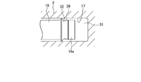
図2は、本発明の一実施形態に係る可変容量斜板式圧縮機のピストン上死点側を示した概念図である。同図に示すように、シリンダブロック2に囲まれたシリンダボア17内には上死点及び下死点の間を往復ピストン運動可能なピストン18が配設されている。ピストン18の外周面上の上死点側部近傍にはピストンリング溝36が形成されている。ピストンリング32は、ピストン18の上死点側に設けられたピストンリング溝36に沿って嵌装されている。
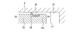
図3は、本発明の一実施形態に係る可変容量斜板式圧縮機のピストン上死点側を示した概念図についての断面図である。同図に示すように、ピストン上死点側34に設けられたピストンリング溝36は、ピストン外周を一定の幅及び深さでリング状に設けられており、そのピストンリング溝36に嵌装されたピストンリング32は、その厚さがピストンリング溝36の深さ寸法より小さく、ピストンリング32の幅はピストンリング溝36の幅寸法に対して同等もしくは若干大きめに設定されている。
同図に示すように、ピストンリング溝36に沿ってリング状のピストンリング32が篏装されている。ピストンリング32はシリンダボア17の内壁に接する外周面側が、凹面となりピストン溝底面側が凸面となっている。ピストンリング32の径の小さい面側はピストンリング溝36の上死点側に配置篏装され、ピストンリング32の径の大きい面側はピストンリング溝36の下死点側に配置嵌装されている。径の大きい面側の外周である下死点側外端部37はピストンリング溝36から迫り出してシリンダボア17の内壁に接する構造で篏装されている。
可変容量斜板式圧縮機のピストン往復運動において、シリンダボア17内の圧縮室31に充填される作動流体は、その大部分が作業冷媒として吐出孔26を経由して圧縮吐出されるが、作動流体には可変容量斜板式圧縮機1の内部摺動部を円滑に駆動させるための潤滑油もミスト状になって含まれている。潤滑油が作業冷媒と共に圧縮機外に吐出されることは圧縮機内の潤滑油の不足及び冷凍サイクルの効率の低下を来すために望ましくない。
このため、ピストン18が下死点から上死点側に移動する圧縮工程時には、圧縮室31のシリンダボア17の壁面に付着する潤滑油をピストン18及びシリンダボア17の内壁間の微小間隙を経由して下死点側であるクランク室8に漏洩させて、作動流体とともに潤滑油が吐出孔から排出されることを制限する必要がある。同様に、ピストン18が上死点から下死点側に移動する吸入工程時には、シリンダボア17の内壁に付着する潤滑油をクランク室21側にかき落とすことによって、クランク室8に潤滑油を供給して、クランク室8内の斜板22及びシュー並びにピストン18の潤滑な駆動を継続維持する必要がある。
図4は、本発明の一実施形態に係る可変容量斜板式圧縮機1のピストンリング32を示した概念図である。同図に示すように、ピストンリング32は略円錐状の立体の裾部を環状に切り出したいわゆるスカート型のリング形状を成しており、その下死点側35において径を大きく、上死点側34において径を小さく形成されてなる構造を有し、下死点側の径はピストン18の径より若干大きく下死点側外周先端部37がシリンダ31の内壁に接触して配置されている。また、ピストンリング32は、外周面において凹面状33を有し、内周面において凸面状を有している。つまりピストンリング32は、外周面が外側に向かって反る形態を有している。
ピストンリング18の材質は、好ましくはシリコン樹脂又はテフロン樹脂等の、少なくともその表面において可撓性を有する高分子樹脂化合物等から成形されている。このため、ピストンリング18には外力が加わることによって伸縮等微小の形状変化を成し得る。しかし本発明は、ピストンリング18の材質を高分子樹脂化合物に限定するものではなく、適度の可撓性を有する材質であれば適用することができることは言うまでもない。
本発明の一実施形態に係る可変容量斜板式圧縮機は、そのピストン往復運動において、ピストンリングが上述した特異構造を有することにより、圧縮室31内に取り込まれた潤滑油をクランク室に漏洩させやすく、逆にクランク室側に漏洩された潤滑油をシリンダボア17内に再び取りこみにくい構造となっている。以下にその構造及び作用を説明する。
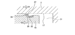
図5は、本発明の一実施形態に係る可変容量斜板式圧縮機のピストンリング18の摺動作用時における断面を示した概念図である。同図に示すように、吸入工程時においてピストン18が下死点側(図中35の矢印側)に運動した際は、シリンダボア17の内壁に付着する潤滑油38は、ピストンリング32の下死点側外端部37がシリンダ31の内壁に密着して下死点側に移動する。このため、この下死点側外端部37によってかき取られるような動作が発生することになって下死点側であるクランク室8側に移動することになる。
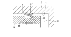
図6は、本発明の一実施形態に係る可変容量斜板式圧縮機のピストンリング18の摺動作用時における断面を示した概念図である。同図に示すように、圧縮工程時においてピストン18が上死点側(図中34の矢印側)に運動した際は、ピストンリング32の下死点側外端部37がシリンダボア17の内壁に密着する強度が弱まるため、シリンダボア17の内壁に付着する潤滑油38は、シリンダボア17の内壁に付着したまま、ピストンリング下死点側外端部37とシリンダボア31との間隙を介して下死点側(図中の35側)に漏洩する。
このように、ピストンリング32の形状が、上死点側においてはピストンリング溝に密着し、下死点側においては径を大きくしてピストン外周外側に迫り出している形態(図3及び図4)をとることによって、前述のようにシリンダ31内壁に存在する潤滑油をクランク室側である下死点側へは送りこみやすく、逆に上死点側であるシリンダボア17内へは取りこまれにくくする。これにより、クランク室8内の潤滑油を潤沢にし摺動箇所の潤滑性を維持しやすくし、同時に冷凍回路への潤滑油の混入排出を抑制できる。つまり空調装置のCOP、可変容量斜板式圧縮機のORC(オイル保持性能)の向上に大きく貢献できる。
因みにこの効果を図7及び図8にベクトルを用いて比較説明する。図7は、本発明の一実施形態に係る可変容量斜板式圧縮機のピストンリングを示した断面概念図である。図8は、可変容量斜板式圧縮機の従来のピストンリングを示した断面概念図である。図8に示す従来のピストンリングでは、本発明に係るピストンリング32と比較して外周面が凸面状を有している。両図に示すように、ピストン18が下死点側に移動することによってシリンダボア17の内壁面はピストンリング32の下死点側外端部37を上死点側に移動させる摩擦力として働く。
この際、図7における本発明の一実施形態に係る可変容量斜板式圧縮機では、ピストンリング32の外周側面は凹面構造をとるためシリンダボア17の内壁面に対して大きな角度θを有する。逆に図8における従来構造のピストンリングは外周面側が凸面を有するため、シリンダ31の内壁面に対して接する角度は小さな角度γとなる。この角度θと角度γとの両角度によって、シリンダ31の内壁面の移動ベクトルを分割すると、図7及び図8に示すようにピストンリング下死点側外端部37がシリンダ内壁面を押しつける能力がベクトルX、ベルトルYで表される。これによりシリンダ31の内壁面に存在するブローバイ/潤滑油をクランク室側である下死点側へとかき戻す能力を、ベクトルXとベルトルYとを比較することによって理解することができる。つまり本発明の一実施形態に係る可変容量斜板式圧縮機のピストンリングにおいては、大きなベクトルXの力が、ピストン18の移動方向と逆の方向に摩擦抵抗力としてシリンダ壁面に対して働くことによって、より大きな力でシリンダ壁面を押さえ、潤滑油をクランク室側である下死点側へとかき戻すことになる、とも理解することができる。
上述したように、ベクトルXとベクトルYとを比較することによって、図7に示す本発明の一実施形態に係る可変容量斜板式圧縮機のピストンリング32の外周側面における凹面形態が、シリンダ31の内壁面に存在する潤滑油をクランク室側である下死点側へとかき戻すために極めて有効な形態であることが理解される。
圧縮機内においては潤滑油は冷媒に比較して大きな粘性及び大きな表面張力を有するため、圧縮室31内においては、シリンダボア17の内壁に略均一に密着塗布された状態で存在する。よって上記のようにピストン摺動においては潤滑油のみがピストンリング32によってクランク室側にかき落とされることとなり、冷媒がクランク室に漏洩する量は微量であると考えられる。
以上からも、本発明に係る可変容量斜板式圧縮機のピストンリング構造はCOP(エネルギー消費効率)やORC(オイル保持性能)向上のために非常に有利な構造であると言える。またピストンリングが可撓性のある合成樹脂で製造された場合は、ピストンリングの耐クリープ性を向上させることができ、耐久性に優れ、加工が容易であるため軽量且つ安価な圧縮機を構成することにつながる。総じて、本発明に係る可変容量斜板式圧縮機のピストン及びシリンダ機構は車載用冷空調システムの長期信頼性や効率を向上させ、自動車全体の効率稼働に大きく貢献するものとなる。
Capacity(冷空調能力)、COP(エネルギー消費効率)、ORC(オイル保持性能)等については比較実験による優位性データを取得確認済みであるが、比較対象の秘密保持のため内容詳細についての明細開示は割愛する。
なお、本発明は上述した実施形態に限定されるものではなく、本発明の主旨を逸脱しない範囲内で種々変更して実施することが可能である。またピストン/シリンダ機構を有する装置及び器具は、可変容量斜板式圧縮機に限定されず適用可能であり、いずれの形態も本技術思想の一部である。
上述したように、本願に係る発明によれば、圧縮室のシール性向上によるCOP(エネルギー消費効率)を改善し、適量のブローバイガスと共に潤滑油をクランク室に漏洩させて、クランク室の潤滑油量向上による諸摺動部の信頼性改善を果たす。それのみならず、特に低速時でもクランク室の潤滑油保持量を適切に確保できる。封入潤滑油量の低減による空調性能向上及び封入潤滑油量の低減によるコスト低減に大きく貢献し、自動車の安全性及び作業性を格段に向上させつつ、経済効率も格段に向上させることの可能な斜板式圧縮機及び空調機器並びにピストンが実現される。
また本発明は、その斜板式圧縮機及び空調機器並びにピストンに限定されることなく、これらを用いたあらゆる産業用途に対しても、利用・適用可能である。よって、本願は、自動車産業の他、各種産業に対して大きな有益性をもたらすものである。
1 可変容量斜板式圧縮機
2 シリンダブロック
3 バルブプレート
4 リアヘッド
5 フロントヘッド
6 締結ボルト
7 ハウジング
8 クランク室
9 シャフト
10 ボルト
11 中継部材
12 駆動プーリ
13 シール部材
14 ラジアル軸受
15 ラジアル軸受
16 貫通孔
17 シリンダボア
18 ピストン
18a ピストン頭部
18b ピストンクランク室係合部
19 スラストフランジ
21 リンク部材
22 斜板
23 ヒンジホール
24 シュー
25 吸入孔
26 吐出孔
27 吸入室
28 吐出室
29 吸入口
30 吸入弁
31 圧縮室
32 ピストンリング
33 ピストンリング凹面
34 ピストン上死点側
35 ピストン下死点側
36 ピストンリング溝
37 下死点側外端部(ピストンリング)
38 ブローバイ/潤滑油
39 摺接面
40 斜板側摺接面
2 シリンダブロック
3 バルブプレート
4 リアヘッド
5 フロントヘッド
6 締結ボルト
7 ハウジング
8 クランク室
9 シャフト
10 ボルト
11 中継部材
12 駆動プーリ
13 シール部材
14 ラジアル軸受
15 ラジアル軸受
16 貫通孔
17 シリンダボア
18 ピストン
18a ピストン頭部
18b ピストンクランク室係合部
19 スラストフランジ
21 リンク部材
22 斜板
23 ヒンジホール
24 シュー
25 吸入孔
26 吐出孔
27 吸入室
28 吐出室
29 吸入口
30 吸入弁
31 圧縮室
32 ピストンリング
33 ピストンリング凹面
34 ピストン上死点側
35 ピストン下死点側
36 ピストンリング溝
37 下死点側外端部(ピストンリング)
38 ブローバイ/潤滑油
39 摺接面
40 斜板側摺接面
Claims (5)
- ハウジング内にクランク室を貫通してこのハウジングに回転自在に支持されたシャフトと、
前記シャフトの回転に応じて前記ハウジングに形成されたシリンダボア内を往復運動するピストンと、
前記ピストンの略円柱状の外周に形成されたピストンリング溝に嵌装され軸方向に沿って凹面状に反っている外側面を有するピストンリングと
を具備することを特徴とする斜板式圧縮機。 - 前記ピストンリングは、厚さが前記ピストンリング溝の深さ以下であり、前記ピストンの下死点側大径の外側端部において前記シリンダボアの内壁面と略円周状に接触していることを特徴とする請求項1に記載の斜板式圧縮機。
- 前記ピストンリングは、可撓性を有する合成樹脂から成り、前記シリンダとの嵌合摺動において前記ピストンの下死点側大径の外側端部が、前記シリンダボアとの摺動に伴う摩擦力に応じてシリンダボア内壁面への押しつけ力が変化することを特徴とする請求項1もしくは2記載の斜板式圧縮機。
- 前記請求項1乃至3のうちいずれか1項記載の斜板式圧縮機を具備する空調機器。
- 略円筒状のシリンダボアの外周に形成されるピストンリング溝と、
前記ピストンリング溝に嵌装され軸方向に沿って凹面状に反っている外側面を有するピストンリングと
を具備することを特徴とするピストン。
Applications Claiming Priority (2)
| Application Number | Priority Date | Filing Date | Title |
|---|---|---|---|
| JP2014-266972 | 2014-12-29 | ||
| JP2014266972 | 2014-12-29 |
Publications (1)
| Publication Number | Publication Date |
|---|---|
| WO2016108275A1 true WO2016108275A1 (ja) | 2016-07-07 |
Family
ID=56284429
Family Applications (1)
| Application Number | Title | Priority Date | Filing Date |
|---|---|---|---|
| PCT/JP2015/086200 Ceased WO2016108275A1 (ja) | 2014-12-29 | 2015-12-25 | 斜板式圧縮機及び空調機器並びにピストン |
Country Status (1)
| Country | Link |
|---|---|
| WO (1) | WO2016108275A1 (ja) |
Cited By (1)
| Publication number | Priority date | Publication date | Assignee | Title |
|---|---|---|---|---|
| WO2023176040A1 (ja) * | 2022-03-15 | 2023-09-21 | 株式会社日立産機システム | 圧縮機 |
Citations (3)
| Publication number | Priority date | Publication date | Assignee | Title |
|---|---|---|---|---|
| JPS6148978U (ja) * | 1984-08-29 | 1986-04-02 | ||
| JPH02118177U (ja) * | 1989-03-09 | 1990-09-21 | ||
| JP2009281232A (ja) * | 2008-05-21 | 2009-12-03 | Sanden Corp | ピストン往復動式圧縮機のピストンリング |
-
2015
- 2015-12-25 WO PCT/JP2015/086200 patent/WO2016108275A1/ja not_active Ceased
Patent Citations (3)
| Publication number | Priority date | Publication date | Assignee | Title |
|---|---|---|---|---|
| JPS6148978U (ja) * | 1984-08-29 | 1986-04-02 | ||
| JPH02118177U (ja) * | 1989-03-09 | 1990-09-21 | ||
| JP2009281232A (ja) * | 2008-05-21 | 2009-12-03 | Sanden Corp | ピストン往復動式圧縮機のピストンリング |
Cited By (3)
| Publication number | Priority date | Publication date | Assignee | Title |
|---|---|---|---|---|
| WO2023176040A1 (ja) * | 2022-03-15 | 2023-09-21 | 株式会社日立産機システム | 圧縮機 |
| JP2023134865A (ja) * | 2022-03-15 | 2023-09-28 | 株式会社日立産機システム | 圧縮機 |
| US12529375B2 (en) | 2022-03-15 | 2026-01-20 | Hitachi Industrial Equipment Systems Co. Ltd. | Compressor |
Similar Documents
| Publication | Publication Date | Title |
|---|---|---|
| KR100320645B1 (ko) | 축 시일링 장치 및 이를 사용하는 압축기 | |
| JPH0544550Y2 (ja) | ||
| US4522112A (en) | Swash-plate type compressor having improved lubrication of swash plate and shoes | |
| JP6225045B2 (ja) | ロータおよびロータリー型流体機械 | |
| US5374168A (en) | Reciprocating piston fluid pump | |
| US6321635B1 (en) | Swash plate type compressor in which lubricating oil is effectively supplied to a shoe mechanism interposed between a piston and a swash plate | |
| WO2016108275A1 (ja) | 斜板式圧縮機及び空調機器並びにピストン | |
| US5380163A (en) | Gas guiding mechanism in a piston type compressor | |
| KR20110035089A (ko) | 사판식 압축기 | |
| KR20170037219A (ko) | 차량용 사판식 압축기 | |
| KR20140096607A (ko) | 사판식 압축기용 슈 | |
| KR102027178B1 (ko) | 양두 사판식 압축기 | |
| JPH09177670A (ja) | ピストン式圧縮機 | |
| JP2015158144A (ja) | ローリングピストンおよびロータリー型流体機械 | |
| JP2587484Y2 (ja) | 斜板式圧縮機 | |
| WO2018207724A1 (ja) | 圧縮機 | |
| JP2020148139A (ja) | 開放型圧縮機 | |
| KR101348854B1 (ko) | 압축기 | |
| KR100741688B1 (ko) | 자전방지구조를 가지는 자동차용 왕복동 사판식 압축기 | |
| WO2009128228A1 (ja) | 圧縮機の潤滑剤供給構造 | |
| KR20180028303A (ko) | 사판식 압축기 | |
| KR20180028302A (ko) | 사판식 압축기 | |
| JP3213891U (ja) | 斜板式圧縮機 | |
| JP2587488Y2 (ja) | 斜板式圧縮機 | |
| KR20040094158A (ko) | 압축기 |
Legal Events
| Date | Code | Title | Description |
|---|---|---|---|
| 121 | Ep: the epo has been informed by wipo that ep was designated in this application |
Ref document number: 15875401 Country of ref document: EP Kind code of ref document: A1 |
|
| NENP | Non-entry into the national phase |
Ref country code: DE |
|
| 122 | Ep: pct application non-entry in european phase |
Ref document number: 15875401 Country of ref document: EP Kind code of ref document: A1 |
|
| NENP | Non-entry into the national phase |
Ref country code: JP |