WO2016104653A1 - 光レセプタクル及び光トランシーバ - Google Patents
光レセプタクル及び光トランシーバ Download PDFInfo
- Publication number
- WO2016104653A1 WO2016104653A1 PCT/JP2015/086113 JP2015086113W WO2016104653A1 WO 2016104653 A1 WO2016104653 A1 WO 2016104653A1 JP 2015086113 W JP2015086113 W JP 2015086113W WO 2016104653 A1 WO2016104653 A1 WO 2016104653A1
- Authority
- WO
- WIPO (PCT)
- Prior art keywords
- optical
- core
- refractive index
- fiber
- optical receptacle
- Prior art date
- Legal status (The legal status is an assumption and is not a legal conclusion. Google has not performed a legal analysis and makes no representation as to the accuracy of the status listed.)
- Ceased
Links
Images




Classifications
-
- G—PHYSICS
- G02—OPTICS
- G02B—OPTICAL ELEMENTS, SYSTEMS OR APPARATUS
- G02B6/00—Light guides; Structural details of arrangements comprising light guides and other optical elements, e.g. couplings
- G02B6/24—Coupling light guides
- G02B6/42—Coupling light guides with opto-electronic elements
- G02B6/4201—Packages, e.g. shape, construction, internal or external details
- G02B6/4204—Packages, e.g. shape, construction, internal or external details the coupling comprising intermediate optical elements, e.g. lenses, holograms
- G02B6/421—Packages, e.g. shape, construction, internal or external details the coupling comprising intermediate optical elements, e.g. lenses, holograms the intermediate optical component consisting of a short length of fibre, e.g. fibre stub
-
- G—PHYSICS
- G02—OPTICS
- G02B—OPTICAL ELEMENTS, SYSTEMS OR APPARATUS
- G02B6/00—Light guides; Structural details of arrangements comprising light guides and other optical elements, e.g. couplings
- G02B6/02—Optical fibres with cladding with or without a coating
-
- G—PHYSICS
- G02—OPTICS
- G02B—OPTICAL ELEMENTS, SYSTEMS OR APPARATUS
- G02B6/00—Light guides; Structural details of arrangements comprising light guides and other optical elements, e.g. couplings
- G02B6/02—Optical fibres with cladding with or without a coating
- G02B6/02004—Optical fibres with cladding with or without a coating characterised by the core effective area or mode field radius
-
- G—PHYSICS
- G02—OPTICS
- G02B—OPTICAL ELEMENTS, SYSTEMS OR APPARATUS
- G02B6/00—Light guides; Structural details of arrangements comprising light guides and other optical elements, e.g. couplings
- G02B6/24—Coupling light guides
- G02B6/36—Mechanical coupling means
- G02B6/38—Mechanical coupling means having fibre to fibre mating means
-
- G—PHYSICS
- G02—OPTICS
- G02B—OPTICAL ELEMENTS, SYSTEMS OR APPARATUS
- G02B6/00—Light guides; Structural details of arrangements comprising light guides and other optical elements, e.g. couplings
- G02B6/24—Coupling light guides
- G02B6/36—Mechanical coupling means
- G02B6/38—Mechanical coupling means having fibre to fibre mating means
- G02B6/3807—Dismountable connectors, i.e. comprising plugs
- G02B6/3833—Details of mounting fibres in ferrules; Assembly methods; Manufacture
- G02B6/3846—Details of mounting fibres in ferrules; Assembly methods; Manufacture with fibre stubs
-
- G—PHYSICS
- G02—OPTICS
- G02B—OPTICAL ELEMENTS, SYSTEMS OR APPARATUS
- G02B6/00—Light guides; Structural details of arrangements comprising light guides and other optical elements, e.g. couplings
- G02B6/24—Coupling light guides
- G02B6/42—Coupling light guides with opto-electronic elements
-
- G—PHYSICS
- G02—OPTICS
- G02B—OPTICAL ELEMENTS, SYSTEMS OR APPARATUS
- G02B6/00—Light guides; Structural details of arrangements comprising light guides and other optical elements, e.g. couplings
- G02B6/02—Optical fibres with cladding with or without a coating
- G02B6/02033—Core or cladding made from organic material, e.g. polymeric material
Definitions
- An aspect of the present invention generally relates to an optical transceiver and module for optical communication, and more particularly to an optical receptacle suitable for a module for high-speed communication.
- An optical receptacle is used as a component for optically connecting an optical fiber connector to an optical element such as a light receiving element or a light emitting element in an optical module of an optical communication transceiver.
- optical communication transceivers are required to increase in speed.
- the shape of a transceiver or the like that adopts a receptacle-type optical module is standardized, and if the modulation speed of an optical signal emitted from a semiconductor laser, which is one of optical elements, is increased, the space required for an electric circuit increases. Therefore, downsizing of the optical module is demanded.
- the mode field diameter of a semiconductor laser element is generally smaller than the core diameter of 10 ⁇ m of an optical fiber used as an optical signal transmission path.
- a single module has a plurality of semiconductor lasers, and light emitted from each semiconductor laser is transmitted into an optical waveguide formed inside a plate-shaped member. Then, an optical module having a structure that is optically coupled to an optical fiber of an optical receptacle after being combined into one waveguide is also used.
- an optical module having a structure that is optically coupled to an optical fiber of an optical receptacle after being combined into one waveguide is also used.
- a lens for condensing light emitted from a semiconductor laser element onto a fiber core or condensing light emitted from a fiber core onto a light receiving element has a difference between the mode field diameter of the optical element and the fiber core diameter. In some cases, it is necessary to have a magnification function. However, the larger the difference, the longer the focal length of the lens, or the larger the number of necessary lenses, and there is a problem that the optical system becomes complicated and expensive.
- the magnification by the lens is kept small. Instead, a lens is formed on a part of the optical fiber side end face of the optical fiber, or a GI fiber is fused.
- a method is known in which the mode field diameter of the incident light is enlarged and the optimum mode field diameter for the fiber is incident on the fiber end face (for example, Reference 1).
- a fiber having different refractive indexes is fused stepwise from the core center to the outer peripheral portion in the radial direction, such as a GI fiber
- a core having a different refractive index is fused in a fusion technique in which the fiber end faces are fused and integrated. Since it melts and mixes, it is difficult to manage the refractive index around the fused part, and there is a problem that optical loss increases.
- the core of the optical element side end surface of the optical fiber is made smaller, and the refractive index difference between the core and the clad than the fiber generally used in the transmission line is reduced. While fusing a large fiber, it contributes to shortening the total length of the optical module, while the refractive index and the fiber are generally used in the transmission line, and the refractive index and the fusion part of the fiber having a large refractive index difference between the core and the clad.
- an optical fiber having a core and a cladding for conducting light, a ferrule having a through hole to which the optical fiber is fixed, and an elastic member for fixing the optical fiber to the through hole, Including a fiber stub and a holder for holding the fiber stub, and the optical fiber has one end surface of the ferrule on the side optically connected to the plug ferrule and the other end surface opposite to the one end surface.
- the optical fiber includes a first portion on the other end surface side, a third portion on the one end surface side, and a second portion between the first portion and the third portion.
- the core diameter in the first part is smaller than the core diameter in the third part, and the core diameter in the second part is from the first part side toward the third part side.
- the elastic member becomes larger , Optical receptacle, characterized in that it is filled in the space between the inner wall of the through hole and the optical fiber.
- FIG. 12A to FIG. 12C are schematic views illustrating analysis relating to the length of the first portion. It is a schematic cross section which illustrates the fiber stub in 3rd embodiment of this invention.
- FIGS. 14A and 14B are schematic views illustrating an optical transceiver in the fourth embodiment of the invention.
- a first invention includes a fiber stub comprising an optical fiber having a core and a cladding for conducting light, a ferrule having a through hole to which the optical fiber is fixed, and an elastic member for fixing the optical fiber to the through hole And a holding tool for holding the fiber stub, and the optical fiber has one end surface on the side that is optically connected to the plug ferrule of the ferrule, and the other end surface opposite to the one end surface,
- the optical fiber has a first portion on the other end surface side, a third portion on the one end surface side, and a second portion between the first portion and the third portion,
- the core diameter in the first part is smaller than the core diameter in the third part, and the core diameter in the second part increases from the first part side toward the third part side
- the elastic member is the light An optical receptacle, characterized in that it is filled in the space between the inner wall of Aiba and the through hole.
- the core diameter at the end surface of the ferrule opposite to the side optically connected to the plug ferrule is smaller than the core diameter at the end surface of the ferrule on the side optically connected to the plug ferrule.
- the length of can be reduced.
- the second portion is formed, a rapid change in the core shape can be suppressed when the first portion transitions to the third portion. Loss can be suppressed.
- the first part and the third part do not change in shape with respect to the axial direction and the loss of light is small, there is no problem regardless of where the second part is located in the inner diameter part of the optical ferrule. As a result, the receptacle can be manufactured economically without requiring precise length control of the fiber.
- the refractive index of the core of the first portion, the refractive index of the core of the second portion, and the refractive index of the core of the third portion are equal to each other,
- the refractive index of the cladding of the first part is smaller than the refractive index of the cladding of the third part, and the refractive index of the cladding of the second part is from the first part side to the third part side. It is an optical receptacle characterized by becoming larger.
- this optical receptacle by using a fiber having a large refractive index difference, light can be confined without scattering even with a small core diameter, and loss when light enters the fiber can be suppressed.
- the second portion since the second portion is formed, it is possible to suppress a sudden change in the refractive index difference when the first portion transitions to the third portion. Loss can be suppressed.
- the core material can be shared and there is no refractive index difference between the cores in the connecting portions of the first part, the second part, and the third part, the loss due to the reflection of the connecting part is suppressed. be able to.
- the refractive index of the cladding of the first portion, the refractive index of the cladding of the second portion, and the refractive index of the cladding of the third portion are equal to each other,
- the refractive index of the core of the first part is larger than the refractive index of the core of the third part, and the refractive index of the core of the second part is from the first part side to the third part side. It is an optical receptacle characterized by becoming smaller toward.
- the clad can be formed of the same material, the clad can have uniform physical properties. Thereby, since the melting point becomes uniform, the outer diameter of the clad at the time of fusion can be easily formed.
- the core diameter of the second part increases linearly from the first part side toward the third part side. Is an optical receptacle.
- the core diameter of the second part increases nonlinearly from the first part side toward the third part side. It is the optical receptacle characterized.
- this optical receptacle since it is not necessary to precisely control the fusion fiber pulling speed, the fusion discharge time, and the power when forming the second portion, it can be manufactured relatively easily. it can.
- the core of the second portion has a core diameter of the second portion from the first portion side to the third portion side.
- An optical receptacle characterized by having a step in a part of a region where is increased.
- this optical receptacle since it is not necessary to precisely control the fusion fiber pulling speed, the fusion discharge time, and the power when forming the second portion, it can be manufactured relatively easily. it can. In addition, if this shape is adopted, even fibers having different melting points can be connected, so that the options of fibers used for fusion can be expanded.
- a seventh invention is an optical receptacle according to any one of the first to sixth inventions, wherein a core diameter in the first portion is 0.5 ⁇ m or more and 8 ⁇ m or less.
- the MFD is reduced on the fiber side with respect to the light emitted from the fine optical waveguide, it is not necessary to zoom the light when entering the fiber. Accordingly, the coupling distance can be shortened and the lens can be simplified.
- the difference between the refractive index of the core and the refractive index of the cladding in the first portion is the difference between the refractive index of the core and the cladding in the third portion. It is an optical receptacle characterized by being larger than the difference from the refractive index.
- the light when transmitting light having a beam waist smaller than that in the third portion, the light can be propagated in a single mode and with little loss.
- the difference between the refractive index of the core and the refractive index of the cladding in the first portion is the difference between the refractive index of the core and the cladding in the second portion. It is an optical receptacle characterized by being larger than the difference from the refractive index.
- the light when transmitting light having a beam waist smaller than that of the second portion in the first portion, the light can be propagated in a single mode and with little loss.
- a tenth aspect of the invention is an optical receptacle according to any one of the first to ninth aspects, wherein a core diameter in the third portion is 8 ⁇ m or more and 20 ⁇ m or less.
- the single mode fiber for optical communication that is currently used generally and the MFD can be aligned, so that the coupling loss caused by the MFD difference when coupled with the plug ferrule can be suppressed.
- the difference between the refractive index of the core and the refractive index of the cladding in the third portion is the difference between the refractive index of the core and the cladding in the second portion. It is an optical receptacle characterized by being smaller than the difference from the refractive index.
- the third portion when transmitting light having a larger beam waist than that of the second portion, light can be propagated in a single mode and with little loss.
- the difference between the refractive index of the core and the refractive index of the cladding in the second portion is from the first portion side to the third portion side. It is an optical receptacle characterized by becoming smaller toward.
- the refractive index gradually decreases from the first part side toward the third part side, thereby preventing a sudden change in the refractive index between the first part and the third part. And light loss due to reflection or scattering at the coupling position of the first part and the third part can be suppressed.
- a thirteenth invention is characterized in that, in any one of the first to twelfth inventions, an outer diameter of the optical fiber in the first portion is equal to an outer diameter of the optical fiber in the third portion. Is an optical receptacle.
- the center axis deviation between the first part and the third part can be prevented, and the fusion caused by the axis deviation can be prevented. Loss can be suppressed.
- a fourteenth invention is characterized in that, in any one of the first to thirteenth inventions, an outer diameter of the optical fiber in the second portion is smaller than an outer diameter of the optical fiber in the first portion. Is an optical receptacle.
- the elastic member exists in a wedge shape on the outer periphery of the second portion where the outer diameter of the optical fiber is narrowed, it is possible to prevent the optical fiber from protruding outward from the ferrule, and to prevent the outer periphery of the optical fiber from being broken. And cracks can be suppressed.
- a fifteenth invention is characterized in that, in any one of the first to fourteenth inventions, an outer diameter of the optical fiber in the second portion is smaller than an outer diameter of the optical fiber in the third portion. Is an optical receptacle.
- the wedge action by the elastic member filled outside the cladding of the second part can be more effectively performed. I can do it.
- the first portion, the second portion, and the third portion are disposed in the through hole over the entire area. It is an optical receptacle characterized by the above.
- optical receptacle since the entire optical fiber is present in the through-hole of the ferrule, it is possible to suppress problems such as bending and cracking of the optical fiber due to external force.
- the first portion has a portion protruding from the ferrule, and the second portion and the third portion are disposed over the entire area.
- An optical receptacle characterized by being disposed in the through hole.
- optical receptacle alignment of the optical element and the optical receptacle can be facilitated by making the optical fiber protrude from the ferrule end face.
- any one of the first to seventeenth aspects of the present invention a part of the end face of the ferrule and the optical fiber on the end face of the fiber stub opposite to the side optically connected to the plug ferrule.
- the optical receptacle is characterized in that an end surface has a predetermined angle from a plane perpendicular to the central axis of the fiber stub.
- a part of the end face of the ferrule and the end face of the optical fiber are polished so as to have a predetermined angle from a plane perpendicular to the central axis of the fiber stub, thereby being connected to the optical receptacle.
- the light reflected by the end face of the optical fiber can be prevented from returning to the light emitting element, and the optical element can be operated stably.
- the first portion, the second portion, and the third portion are integrally formed. It is.
- optical receptacle by forming the optical fiber integrally, it is possible to suppress the optical loss by preventing the generation of voids at the boundaries of the first part, the second part, and the third part.
- a twentieth aspect of the present invention is the optical receptacle according to any one of the first to nineteenth aspects, wherein the length of the first portion along the central axis of the fiber stub is 5 ⁇ m or more. .
- optical receptacle it is possible to suppress optical loss due to variations in the length of optical fiber and polishing.
- a twenty-first invention is the optical receptacle according to any one of the first to twentieth inventions, wherein the length of the third portion along the central axis of the fiber stub is 5 ⁇ m or more. .
- optical receptacle it is possible to suppress optical loss due to variations in the length of optical fiber and polishing.
- a twenty-second invention is an optical transceiver comprising any one of the first to twenty-first optical receptacles.
- the core on the optical element side end face of the optical fiber is made small, and a fiber having a refractive index difference between the core and the clad larger than that of a fiber generally used for a transmission path is fused. While contributing to shortening the overall length of the module, a part where the refractive index and core diameter gradually change is formed in the fused part of the fiber generally used in the transmission line and the fiber having a large refractive index difference between the core and the cladding. Thus, the conversion efficiency of the mode field can be suppressed, and as a result, a decrease in coupling efficiency from the optical element to the plug ferrule can be suppressed.
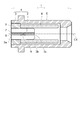
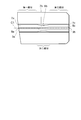
- FIG. 1 is a schematic cross-sectional view of an optical receptacle showing a first embodiment of the present invention.
- the optical receptacle 1 includes a fiber stub 4 including an optical fiber 2, a ferrule 3 having a through hole 3 c that holds the optical fiber 2, and an elastic member 9, a holder 5 that holds the fiber stub 4, and a tip of the fiber stub 4. Is held at one end, and at the other end is a sleeve 6 capable of holding a plug ferrule inserted into the optical receptacle 1.
- the optical fiber 2 is bonded and fixed to the through-hole 3 c of the ferrule 3 using an elastic member 9. Note that the plug ferrule to be inserted into the optical receptacle 1 is not shown.
- ferrule 3 examples include ceramics and glass. In this embodiment, zirconia ceramics is used, and the optical fiber 2 is bonded and fixed to the center of the ferrule 3 to be optically connected to the plug ferrule (end face 3b: FIG. 1). And a convex spherical surface. In assembling the optical receptacle 1, the fiber stub 4 is often press-fitted and fixed to the holder 5.
- the material suitable for the sleeve 6 includes resin, metal, ceramics, etc.
- a split sleeve made of zirconia ceramics having slits in the full length direction was used.
- the sleeve 6 holds the tip (end face 3b) polished on the convex spherical surface of the fiber stub 4 at one end, and holds the plug ferrule to be inserted into the optical receptacle at the other end.
- the optical fiber 2 has a core 8 extending along the central axis C1 and a clad 7 surrounding the core 8.
- the refractive index of the core is higher than the refractive index of the cladding.
- quartz glass can be cited. Impurities may be added to the quartz glass.
- the fiber stub 4 has one end face (end face 3b) optically connected to the plug ferrule and the other end face (end face 3a) opposite to the one end face.
- the core 8 is exposed from the clad 7 at the end face 3a and the end face 3b.
- an optical element such as a semiconductor laser element is disposed on the end face 3a side.
- Light emitted from a semiconductor laser element or the like enters the optical receptacle 1 from the end face 3 a side and propagates in the core 8.
- the light incident on the core 8 from the end surface 3b propagates in the core 8 and is emitted from the end surface 3a side toward the optical element.
- An optical element such as an isolator may be provided between the end face 3a and an optical element such as a semiconductor laser element.
- the isolator has, for example, an element (such as a Faraday element) that rotates a polarization angle or a polarizer, and transmits light only in one direction. Thereby, for example, damage to the laser element due to the return light reflected by the end face 3a, noise, and the like can be suppressed.
- the fiber stub 4 may be polished so that the end surface 3b is inclined with respect to a plane orthogonal to the central axis C1. That is, the convex spherical end surface 3b may be an oblique convex spherical surface that is inclined with respect to a plane orthogonal to the central axis C1.
- the optical receptacle 1 is optically connected to an APC (AngledngPhysical Contact) connector at the end face 3b, and reflection and connection loss at the connection point can be suppressed.
- FIG. 2 is an enlarged cross-sectional view of the fiber stub in the first embodiment of the present invention.
- the optical fiber 2 is a single fiber in which a first portion (first portion 21), a second portion (second portion 22), and a third portion (third portion 23) are fused.
- the first portion of the optical fiber 2 includes a first partial cladding 7a and a first partial core 8a
- the second portion includes a second partial cladding 7b and a second partial core 8b
- the third portion includes a third partial cladding 7c and a third portion.
- the core 8c comprises a fiber stub 4 polished on the convex spherical surface, a third portion on the end surface 3b side, a second portion in the center, and a first portion on the end surface 3a side optically connected to the optical element opposite to the end surface 3b. Is arranged.
- the first partial cladding 7a, the second partial cladding 7b, and the third partial cladding 7c are included in the cladding 7 described with reference to FIG.
- the first partial core 8a, the second partial core 8b, and the third partial core 8c are included in the core 8 described with reference to FIG.
- the core diameter D1 of the first part is smaller than the core diameter D3 of the third part, and the core diameter D2 of the second part gradually increases as the transition from the first part to the third part (see, for example, FIG. 3).
- the fiber outer diameter D4 of the first portion and the fiber outer diameter D6 of the third portion are the same, but the fiber outer diameter D5 of the second portion is smaller than them (see, for example, FIG. 3).
- the core diameter is the length of the core along the direction orthogonal to the optical axis (center axis C1), that is, the core diameter.
- the fiber outer diameter is the fiber length (cladding length) along the direction orthogonal to the central axis C1, that is, the fiber diameter.
- Examples of the method for forming the second part include a method of stretching the optical fiber fusion part while applying heat higher than the melting point of quartz from the outer periphery of the fusion part when the first part and the third part are fused.
- the length of the second portion of the fiber stub 4 in the direction of the central axis C1 needs to be designed in consideration of the length with the least loss and the limit length that can be extended while applying heat.
- the length is desirably 10 micrometers ( ⁇ m) or more and 1000 ⁇ m.
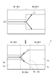
- FIG. 3, FIG. 4, FIG. 5, FIG. 6 and FIG. 7 show the shape of the second part.
- FIG. 3 shows a state in which the core diameter D2 of the second part linearly expands as it changes from the first part to the third part.
- FIG. 5 shows a state in which the core diameter D2 of the second part increases nonlinearly as it changes from the first part to the third part.
- FIG. 6 shows that while the core diameter D2 of the second part changes from the first part to the third part, the core expands nonlinearly, but a part of the boundary between the clad 7 and the core 8 extends to the fiber center axis C1.
- a state is shown in which a portion S1 (this is referred to as a step) is substantially vertical.
- the difference between the refractive index of the cladding and the refractive index of the core in each part is the largest in the first part, then the second part is the largest, and the third part is the smallest. Because the second part is formed at the time of fusing the first part and the third part, the refractive index difference is large on the first part side, and the refractive index difference is gradually reduced toward the third part side.
- the laser When the laser is focused to a certain beam waist diameter D7, it has the characteristic of spreading at a spread angle of ⁇ degrees. That is, if one of the divergence angle or the beam diameter is determined, the other is inevitably determined.
- the refractive index difference between the core and the clad As a method for producing a refractive index difference between the core and the clad, a method of adding rare earth such as erbium or germanium to quartz glass is known, and examples of the addition target include the core, the clad, or both.
- the refractive index can be adjusted by the additive substance and concentration in the quartz glass.
- the refractive index of the core and the refractive index of the cladding are about 1.4 or more and 1.6 or less, respectively.
- the fiber used for the first portion has a refractive index difference so that the spread angle ⁇ of the laser incident on the first portion matches the NA. It is necessary to use a fixed fiber.
- the incident diameter is also determined. Therefore, it is necessary to use a fiber having an MFD (mode field diameter) matched to the incident beam diameter together with the refractive index difference.
- MFD mode field diameter
- the length of the first part and the third part in the direction of the central axis C1 is preferably 100 ⁇ m or more in order to secure the distance until the incident light settles in a single mode, and the second part penetrates the ferrule 3. It is desirable to adjust so that it may be arrange
- the optical fiber 2 is fixed to the through hole 3 c of the ferrule 3 using an elastic member (adhesive) 9.
- the material suitable for the adhesive include resin-based adhesives such as epoxy and silicon. In this example, a high-temperature curing type epoxy-based adhesive was used.
- a space existing between the optical fiber 2 and the inner wall of the ferrule 3 is filled with the same adhesive without any gap.
- the fiber outer diameter D5 of the second portion is smaller than the fiber outer diameter D4 of the first portion and smaller than the fiber outer diameter D6 of the third portion.
- a gap is generated between the ferrule 3 and the outer periphery of the fiber of the second portion in 3c.
- the gap is filled with the elastic member 9 as an adhesive without any gap.
- the second part is formed by fusing the first part and the third part, the strength of the second part is lower than the strength of the first part or the third part depending on the forming conditions. There is a case.
- the second portion can be reinforced by filling the outer periphery of the second portion with the elastic member 9.
- the fiber outer diameter D5 of the second portion may be substantially the same as the fiber outer diameter D4 of the first portion or the fiber outer diameter D5 of the third portion. Good. By taking this shape, it is possible to relatively easily control the discharge amount and the discharge timing when the optical fiber 2 is formed by fusing.
- the end surface 2a of the optical fiber 2 is a plane substantially perpendicular to the central axis C1 of the ferrule 3 (same as the central axis of the fiber stub). It is polished to become.
- substantially perpendicular is preferably about 85 to 95 degrees with respect to the central axis C1.
- the end face 2a of the optical fiber 2 is polished to a plane perpendicular to the central axis C1 of the fiber stub 4, and the end face 2a of the optical fiber 2 and the end face 3a of the ferrule 3 are further polished. Exist on the same plane.
- the distance between the end face 2a of the optical fiber 2 and the end face 3a of the ferrule 3 is about ⁇ 250 nm to +250 nm.
- the center of the core 8 of the optical fiber 2 is within the range of 0.005 millimeters (mm) from the center of the ferrule 3 on the end surface 3a opposite to the end surface 3b polished to the convex spherical surface of the fiber stub 4.
- the convex spherical surface of the fiber stub 4 is usually formed on a plane perpendicular to the central axis C1 of the ferrule 3, but is formed on a plane having a predetermined angle (for example, 4 to 10 degrees) from the perpendicular surface. May be.
- FIG. 8 is a schematic cross-sectional view of an optical receptacle showing a second embodiment of the present invention.
- the members constituting the optical receptacle 1 are the same as in the first embodiment, and the end surface 3b (see FIG. 8) polished to the convex spherical surface of the ferrule 3 having the optical fiber 2 and the through hole 3c for holding the optical fiber 2.
- a part of the end face 2a of the optical fiber 2 and a part of the end face 3b of the ferrule 3 is at a predetermined angle (for example, 4 from the plane perpendicular to the central axis C1 of the ferrule 3). It is polished so as to be a flat surface having a degree of 10 degrees.
- the optical fiber 2 is inserted into the through hole 3c of the ferrule 3 and an adhesive is used. After fixing, the ferrule 3 and the optical fiber 2 are formed by polishing simultaneously.
- an elastic member for fixing the optical fiber 2 in the through hole 3c of the ferrule 3 on the outer periphery of the portion 2b where the outer diameter of the second portion is reduced.
- Agent 9 is filled.
- FIG. 9 to 11 are schematic diagrams illustrating examples of analysis conditions and analysis results used in the study.
- FIG. 9 is a schematic cross-sectional view showing the optical fiber used in this study.
- a beam having a beam waist having a diameter w1 is incident on a fiber having an MFD having a diameter w2
- the coupling efficiency ⁇ is It is known that it is required in
- the MFD of a single mode fiber has a diameter that is 0.5 to 4 ⁇ m larger than the core diameter of the fiber, although it varies depending on the wavelength when the core diameter is in the range of 0 to 10 ⁇ m. From this fact, it is desirable that the core diameter of the fiber is smaller by 0.5 to 4 ⁇ m than the incident beam waist.
- the divergence angle ⁇ 1 can be obtained.
- the light receiving angle ⁇ 2 of the fiber is As can be seen from the above, it is found from the refractive index n core of the core and the refractive index n clad of the cladding.
- the refractive index of the core and the clad changes in the range of about 1.4 to 1.6.
- the length of the second part in the direction of the central axis C1 will be described.
- optical CAE analysis was performed.
- the core diameter D1 of the first part is 3 ⁇ m
- the refractive index of the first part core 8a is 1.49
- the core diameter D3 of the third part is 8.2 ⁇ m
- the refractive index of the third part core 8c is 1.4677
- fiber The total length was 1000 ⁇ m
- the refractive indexes of the clads (7a, 7b, and 7c) in each part were 1.4624 in common
- the beam waist diameter D7 of the incident beam was 3.2 ⁇ m.
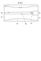
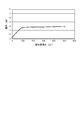
- Fig. 10 shows a graph summarizing the analysis results of this analysis.
- the horizontal axis indicates the length of the second portion in the direction of the central axis C1
- the vertical axis indicates the logarithm of the light intensity at the fiber exit end when the incident light is 1.
- FIG. 11 is a contour diagram and a graph showing the light intensity distribution in the fiber in an example of the analysis conditions.
- the vertical axis of the graph indicates the distance from the incident end of the fiber, and the horizontal axis indicates the light intensity.
- the incident light is initially reduced in intensity due to light interference, but is stabilized when it has propagated to some extent from the exit end.
- the second part is entered while maintaining a constant value.
- loss due to MFD conversion and refractive index change occurs, so that the light intensity decreases, and then enters the third part.
- the third part there is almost no change in intensity, and a constant value is maintained until the emission end.
- the length of the first portion and the third portion in the direction of the central axis C1 does not affect the attenuation. There is no effect.
- the lengths of the first part and the third part can be designed with any length of the designer, and the dimensional tolerance of the design dimension can be made large. This advantage does not require strict dimensional accuracy like GI fiber or fiber with lens, and can greatly contribute to the improvement of mass productivity.
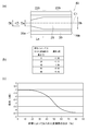
- FIG. 12A to FIG. 12C are schematic views illustrating an example of an optical receptacle of a reference example used for the study on the length of the first portion and an analysis result thereof.
- the optical receptacle of the reference example has a fiber stub 49 shown in FIG.
- the structure of the fiber stub 49 of the reference example is the same as the structure in which the first portion 21 (the first partial cladding 7a and the first partial core 8a) is not provided in the fiber stub 4 according to the embodiment. That is, the fiber stub 49 includes an optical fiber 29 and a ferrule 39 that holds the optical fiber 29.
- the fiber stub 49 has an end face 39b connected to the plug ferrule and an end face 39a opposite to the end face 39b.
- the optical fiber 29 has a second portion 229 (conversion unit) and a third portion 239.
- the third portion 239 is aligned with the second portion 229 in the axial direction and is continuous with the second portion 229.
- the second part 229 forms part of the end face 39a, and the third part 239 forms part of the end face 39b.
- the core diameter of the second portion 229 increases toward the third portion 239.
- the core diameter of the third portion 239 is substantially constant in the direction of the central axis C1. In FIG. 12A, for convenience, some elements such as an elastic member are omitted.
- the end surface 39a is polished in a mirror shape.
- the end surface 39b is polished into a convex spherical shape. Thereby, the loss of light at the end faces 39a and 39b can be suppressed.
- the polishing amount of the end face 39a is, for example, not less than 5 ⁇ m and not more than 50 ⁇ m. Thereby, a mirror-like end surface can be formed.
- the length of the second portion 229 is shortened according to the polishing amount.
- the end surface position of the second portion 229 (the position of the portion exposed as part of the end surface 39a of the second portion 229) varies by about 5 to 50 ⁇ m according to the polishing amount. That is, the core diameter Da on the end face 39a varies. This causes a loss when using a fiber whose MFD changes periodically, such as a GI fiber.
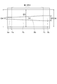
- FIG. 12B and FIG. 12C show examples of analysis results.
- the length La along the axial direction of the second portion 229 was 50 ⁇ m
- the core diameter Da at the end face 39a was 3 ⁇ m
- the core diameter Db at the end face 39b was 9 ⁇ m.
- the rate of change along the axial direction of the core diameter in the second portion 229 was constant.
- FIG. 12B shows a fiber stub 49 having the length La of 20% (polishing amount of 10 ⁇ m), 40% (polishing amount of 20 ⁇ m), 60% (polishing amount of 30 ⁇ m), or the like. It represents the loss (dB) when shortened by 80% (polishing amount 40 ⁇ m).
- the loss is -1.06 dB before the end face 39a is polished. From the graph, it can be seen that the loss increases as the second portion 229 is shortened by polishing. For example, when the conversion portion (second portion 229) is shortened by 50% by polishing, the loss is about ⁇ 3 dB.
- the loss increases by polishing the end face.
- the loss varies depending on the variation in the polishing amount. The amount of polishing needs to be strictly controlled, and mass productivity may be reduced.
- a first portion in which the core diameter and the refractive index do not substantially change along the central axis C1 is provided. Even if the length of the first portion along the central axis C1 varies due to the polishing of the end surface 3a, an increase in optical loss and a variation in variation are small. For example, even if the end face position changes within the length of the first portion, the characteristics of the optical receptacle are not substantially deteriorated.
- the length of the first portion along the central axis C1 is equal to or greater than the polishing amount of the end surface 3a.
- the end surface 3a is polished by about 5 ⁇ m or more and 50 ⁇ m or less.
- the length of the first portion along the central axis C1 is desirably 5 ⁇ m or more, and more desirably 50 ⁇ m or more if possible.
- the upper limit of the length along the central axis C1 of the first part is not particularly limited as long as the second part and the third part can be disposed in the fiber stub 4 (in the through hole of the ferrule 3). Therefore, depending on the overall length of the fiber stub 4, the first portion may be extended to about 7 to 10 mm. Thereby, mass productivity can be improved.
- FIGS. 12A to 12C The description regarding FIGS. 12A to 12C is the same in the reference example having no third part, for example. That is, in this case, the core diameter at the end face connected to the plug ferrule varies depending on the polishing amount. Loss increases due to changes in the core diameter at the end face.
- a third portion in which the core diameter and the refractive index do not substantially change along the central axis C1 is provided. Even if the length of the third portion along the central axis C1 varies due to the polishing of the end surface 3b, an increase in optical loss and a variation in variation are small.
- the length of the third portion along the central axis C1 is preferably equal to or greater than the polishing amount of the end surface 3b.
- the end surface 3b is polished by about 5 ⁇ m or more and 20 ⁇ m or less.
- the length of the third portion along the central axis C1 is preferably 5 ⁇ m or more, and more preferably 20 ⁇ m or more if possible.
- the upper limit of the length of the third portion along the central axis C1 is not particularly limited as long as the first portion and the second portion can be disposed in the fiber stub 4 (in the through hole of the ferrule 3). Therefore, depending on the overall length of the fiber stub 4, the third portion may be extended to about 7 to 10 mm. Thereby, mass productivity can be improved.
- the core diameter D1 of the end surface 3a opposite to the end surface 3b polished to the convex spherical surface of the fiber stub 4 is smaller than the core diameter D2 of the end surface 3b polished to the convex spherical surface.
- the length of the optical module can be reduced. Further, it is possible to eliminate the need for highly accurate dimensional management with respect to the axial lengths of the first portion and the third portion. Since the fiber outer diameter D5 of the second portion is smaller than the cladding through-hole 3c, the elastic member 9 is filled in the gap, thereby preventing the fiber from moving in the central axis direction.
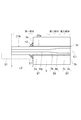
- FIG. 13 is a schematic cross-sectional view illustrating a part of an optical receptacle according to the third embodiment of the invention.
- FIG. 13 shows an enlarged view of the fiber stub 4 in the optical receptacle according to the present embodiment.
- the first portion includes a portion (inner side portion 21 a) disposed in the through hole 3 c of the ferrule 3 and a portion (projecting portion) disposed outside the through hole 3 c. 21b).
- the optical receptacle according to the present embodiment has an elastic member 19. Except for the above, this embodiment is the same as the first or second embodiment.
- the protruding portion 21b protrudes outward from the ferrule 3 (the surface of the ferrule 3 opposite to the end surface 3b). That is, the protrusion 21b is not aligned with the ferrule 3 in the direction orthogonal to the central axis C1.
- the inner portion 21a is aligned with the ferrule 3 in a direction orthogonal to the central axis C1, and is surrounded by the ferrule 3 when viewed along the central axis C1.
- the entire area of the second portion and the entire area of the third portion are respectively disposed in the through holes 3c. That is, the entire area of the second portion and the entire area of the third portion are aligned with the ferrule 3 in a direction orthogonal to the central axis C1, and are surrounded by the ferrule 3 when viewed along the central axis C1.
- a module such as a semiconductor laser element and an optical element are provided on the side opposite to the end face 3b of the optical receptacle.
- FIG. 13 shows a part 31 of the optical element as an example.
- the portion 31 of the optical element has a shape (such as a groove) corresponding to the protruding portion 21b.
- the projecting portion 21b is placed on the part 31 of the optical element and pressed directly against the light emitting end of the optical element.
- light is made incident on the protruding portion 21 from the light emitting end using an element such as a lens.
- the elastic member 19 is provided at the end of the protruding portion 21b on the third portion side.
- the elastic member 19 is in contact with the protruding portion 21b and the ferrule 3, for example. Thereby, the elastic member 19 protects the first portion.
- the length L1 along the direction of the central axis C1 of the elastic member 19 is, for example, about 2 mm.
- the length L2 along the direction of the central axis C1 of the protruding portion 21b is desirably 2 mm or more.
- the length L2 of the protruding portion 21b is desirably 20 mm or less.
- the 2nd part and the 3rd part are arrange
- FIGS. 14A and 14B are schematic views illustrating an optical transceiver according to the fourth embodiment of the invention.
- the optical transceiver 200 according to the present embodiment includes the optical receptacle 1, the optical element 110, and the control board 120.
- a circuit or the like is formed on the control board 120.
- the control board 120 is electrically connected to the optical element 110.
- the control board 120 controls the operation of the optical element 110.
- the optical element 110 is, for example, a light receiving element or a light emitting element.
- the optical element 110 is a light emitting unit.
- the optical element 110 includes a laser diode 111 and a lens 112.
- the laser diode 111 is controlled by the control board 120 and emits light to the fiber stub 4 of the optical receptacle 1.
- the lens 112 is located between the optical receptacle 1 and the laser diode 111 on the optical path of the emitted light.
- the optical element 110 may include an element 113 as illustrated in FIG.
- the element 113 includes a laser diode and an optical waveguide having a small core diameter. Light propagating through the core of the waveguide enters the optical receptacle 1 through the lens 112.
- the optical waveguide is formed by, for example, silicon photonics. A quartz waveguide may be used as the optical waveguide. In the embodiment, the light emitted from the laser diode or the optical waveguide may be directly incident on the optical receptacle 1 without providing the lens 112.
- a plug ferrule 50 is inserted into the optical receptacle 1.
- the plug ferrule 50 is held by the sleeve 6.
- the optical fiber 2 is optically connected to the plug ferrule 50 at the end face 3b.
- the optical element 110 and the plug ferrule 50 are optically connected via the optical receptacle, and optical communication is possible.
- an optical receptacle and an optical transceiver capable of preventing a decrease in coupling efficiency by suppressing the axial movement of the fiber and suppressing a loss of MFD conversion are provided.
Landscapes
- Physics & Mathematics (AREA)
- General Physics & Mathematics (AREA)
- Optics & Photonics (AREA)
- Optical Couplings Of Light Guides (AREA)
Abstract
コアとクラッドを有する光ファイバと貫通孔を有するフェルールと光ファイバをフェルールに固定する弾性部材とを含むファイバスタブと、ファイバスタブを保持する保持具と、を備え、光ファイバは、コア径が小さくコアとクラッドの屈折率差が大きい第一部分と、コア径が大きくコアとクラッドの屈折率差が小さい第三部分と、コア径が第一部分の径から第三部分の径まで推移し、コアとクラッドの屈折率差が第一部分の屈折率差以下かつ第三部分の屈折率差以上の間で推移する第二部分を有し、弾性部材は光ファイバと貫通孔の内壁との間の空間に充填された光レセプタクルが提供される。
Description
本発明の態様は、一般に、光通信用の光トランシーバ、モジュールに係り、特に高速通信用モジュールに好適な光レセプタクルに関する。
光レセプタクルは、光通信用トランシーバの光モジュールにおいて光ファイバコネクタを受光素子や発光素子等の光素子と光学的に接続させるための部品として用いられる。
近年、IPトラフィックの増加に伴い光通信用トランシーバは高速化が要求されている。一般に、レセプタクル型光モジュールを採用するトランシーバ等の形状は規格化されており、光学素子の1つである半導体レーザーから出射する光信号の変調速度を高速化すると、電気回路に必要なスペースが大きくなり、光モジュールの小型化が求められている。
半導体レーザー素子のモードフィールド径は、一般的に光信号の伝送路として用いられる光ファイバのコア径10μmよりも小さい。
近年では光トランシーバの通信速度をより高速化するため、単一のモジュール内に複数の半導体レーザーを有し、各半導体レーザーから出射された光を、板状部材の内部に形成された光導波路内で1つ導波路に合波した後、光レセプタクルの光ファイバと光学的に結合する構造の光モジュールも使われている。これらの光モジュールでは、小型化するために前述の光導波路を持つ板状部材を小型化する必要があり、光導波路のコア径は小さくなる傾向がある。
発光素子に代えて受光素子を用いる光モジュールにおいても、より高速、より長距離通信用途で用いるために、受光素子の受光径を小さくする傾向がある。
半導体レーザー素子から出射された光をファイバコアに集光する、またはファイバコアから出射された光を受光素子に集光するためのレンズは、光学素子のモードフィールド径とファイバコア径に差がある場合には倍率機能を有する必要があるが、差が大きければ大きいほど、レンズの焦点距離が長くなる、または必要レンズ枚数が多くなり光学系が複雑かつ高価になる問題があった。
モジュール全長が長くなることまたは光学系の複雑化を防ぐために、レンズによる倍率は小さく抑え、代わりに光ファイバの光学素子側端面の一部のファイバ先端にレンズを形成したり、GIファイバを融着することで入射された光のモードフィールド径を拡大しファイバに最適なモードフィールド径をファイバ端面に入射する方法が知られている(例えば参考文献1)。
しかしながら先行文献1の方法は、周期的にモードフィールド径が変化するGIファイバを用いるため、最適なモードフィールド径を得るためにはGIファイバの長さを厳密に管理しなければならず、製造上の管理が困難であるという課題があった。
また、GIファイバのように径方向に対してコア中心から外周部にかけて段階的に屈折率が異なるファイバを融着するとき、ファイバ端面を溶かして一体化させる融着技術では屈折率の異なるコアが溶け出し混ざりあってしまうため、融着部周辺の屈折率を管理することが困難であり、光損失が大きくなってしまう課題があった。
本発明の態様は、上記問題を解決するためになされたもので、光ファイバの光学素子側端面のコアを小さくし、かつ一般的に伝送路に用いられるファイバよりもコアとクラッドの屈折率差の大きいファイバを融着することで、光モジュール全長を短くすることに貢献しながら、一般的に伝送路に用いられるファイバとコアとクラッドの屈折率差の大きいファイバの融着部分に屈折率およびコア径が緩やかに推移する部分を形成することで、モードフィールドの変換効率を抑え、結果として光学素子からプラグフェルールまでの結合効率の低下を抑制することができる光レセプタクル及び光トランシーバを提供することを目的とする。
本発明の一態様によれば、光を導通するためのコアとクラッドを有する光ファイバ、前記光ファイバが固定される貫通孔を有するフェルール、前記光ファイバを前記貫通孔に固定する弾性部材、を含むファイバスタブと、前記ファイバスタブを保持する保持具と、を備え、前記光ファイバは、前記フェルールのプラグフェルールと光学的接続する側の一端面と、前記一端面とは反対側の他端面を有し、前記光ファイバは、前記他端面側の第1の部分と、前記一端面側の第3の部分と、前記第1の部分と前記第3の部分との間に第2の部分を有し、前記第1の部分におけるコア径は、前記第3の部分におけるコア径より小さく、前記第2の部分におけるコア径は、前記第1の部分側から前記第3の部分側に向かって大きくなり、前記弾性部材は、前記光ファイバと前記貫通孔の内壁との間の空間に充填されたことを特徴とする光レセプタクルが提供される。
第1の発明は、光を導通するためのコアとクラッドを有する光ファイバ、前記光ファイバが固定される貫通孔を有するフェルール、前記光ファイバを前記貫通孔に固定する弾性部材、を含むファイバスタブと、前記ファイバスタブを保持する保持具と、を備え、前記光ファイバは、前記フェルールのプラグフェルールと光学的接続する側の一端面と、前記一端面とは反対側の他端面を有し、前記光ファイバは、前記他端面側の第1の部分と、前記一端面側の第3の部分と、前記第1の部分と前記第3の部分との間に第2の部分を有し、前記第1の部分におけるコア径は、前記第3の部分におけるコア径より小さく、前記第2の部分におけるコア径は、前記第1の部分側から前記第3の部分側に向かって大きくなり、前記弾性部材は、前記光ファイバと前記貫通孔の内壁との間の空間に充填されたことを特徴とする光レセプタクルである。
この光レセプタクルによれば、フェルールのプラグフェルールと光学的接続する側とは反対側の端面におけるコア径が、フェルールのプラグフェルールと光学的接続する側の端面におけるコア径よりも小さいため、光モジュールの長さを小さくすることができる。
また、第2の部分を形成することで、第1の部分から第3の部分へ推移していく際に、コア形状の急激な変化を抑えることができるため、第2の部分での光学的損失を抑えることができる。
さらに、第1の部分と第3の部分は形状が軸方向に対して変化せず、光の損失も小さいため、第2の部分は光フェルール内径部のどこに所在しても問題はない。これにより、ファイバの精密な長さ管理を必要とせず、経済的にレセプタクルを製造することができる。
また、第2の部分を形成することで、第1の部分から第3の部分へ推移していく際に、コア形状の急激な変化を抑えることができるため、第2の部分での光学的損失を抑えることができる。
さらに、第1の部分と第3の部分は形状が軸方向に対して変化せず、光の損失も小さいため、第2の部分は光フェルール内径部のどこに所在しても問題はない。これにより、ファイバの精密な長さ管理を必要とせず、経済的にレセプタクルを製造することができる。
第2の発明は、第1の発明において、前記第1の部分のコアの屈折率、前記第2の部分のコアの屈折率、および前記第3の部分におけるコアの屈折率は互いに等しく、前記第1の部分のクラッドの屈折率は、前記第3の部分のクラッドの屈折率より小さく、前記第2の部分のクラッドの屈折率は、前記第1の部分側から前記第3の部分側に向かって大きくなることを特徴とする光レセプタクルである。
この光レセプタクルによれば、屈折率差の大きいファイバを用いることで、小さいコア径でも光を散乱させること無く閉じ込めることができ、光がファイバに入射する際の損失を抑えることができる。また、第2の部分を形成することで、第1の部分から第3の部分へ推移していく際に、屈折率差の急激な変化を抑えることができるため、第2の部分での光学的損失を抑えることができる。また、コアの素材を共通化することができ、第1の部分、第2の部分、第3の部分の接続部におけるコア同士の屈折率差が存在しないため、接続部の反射による損失をおさえることができる。
第3の発明は、第1の発明において、前記第1の部分のクラッドの屈折率、前記第2の部分のクラッドの屈折率、および前記第3の部分におけるクラッドの屈折率は、互いに等しく、前記第1の部分のコアの屈折率は、前記第3の部分のコアの屈折率より大きく、前記第2の部分のコアの屈折率は、前記第1の部分側から前記第3の部分側に向かって小さくなることを特徴とする光レセプタクルである。
この光レセプタクルによれば、クラッドが同一素材で形成できるため、クラッドが一様な物性を持つことができる。それにより、融点も一様になるため融着時のクラッド外径の成形を容易に行うことができる。
第4の発明は、第1~3いずれか1つの発明において、前記第2の部分のコア径は、前記第1の部分側から前記第3の部分側に向かって線形に大きくなることを特徴とする光レセプタクルである。
この光レセプタクルによれば、第2の部分に進入したレーザーが放射状に広がっていったとしても、クラッドとコアの境界には小さい角度で入射されることとなり、光が全反射することによりクラッド側に光が逃げていくことを防ぐことができる。
第5の発明は、第1~3のいずれか1つの発明において、前記第2の部分のコア径は、前記第1の部分側から前記第3の部分側に向かって非線形に大きくなることを特徴とする光レセプタクルである。
この光レセプタクルによれば、第2の部分を形成する際の融着ファイバ引っ張り速度、融着放電時間やパワーに精度の高い制御を必要としないため、製造が比較的容易に可能とすることができる。
第6の発明は、第1~3のいずれか1つの発明において、前記第2の部分のコアは、前記第1の部分側から前記第3の部分側にかけて、前記第2の部分のコア径が大きくなっている領域の一部に段差を有することを特徴とする光レセプタクルである。
この光レセプタクルによれば、第2の部分を形成する際の融着ファイバ引っ張り速度、融着放電時間やパワーに精度の高い制御を必要としないため、製造が比較的容易に可能とすることができる。また、この形状を取れば融点の異なるファイバでも接続することができるため、融着に用いるファイバの選択肢を広げることができる。
第7の発明は、第1~6のいずれか1つの発明において、前記第1の部分におけるコア径が、0.5μm以上、8μm以下であることを特徴とする光レセプタクルである。
この光レセプタクルによれば、微細な光導波路から放出された光に対して、ファイバ側がMFDを小さくすることで、ファイバに入射する際に光のズームを必要としなくなる。それにより結合距離の短縮を図れると共に、レンズの簡略化にも貢献することができる。
第8の発明は、第1~7のいずれか1つの発明において、前記第1の部分におけるコアの屈折率とクラッドの屈折率との差は、前記第3の部分におけるコアの屈折率とクラッドの屈折率との差より大きいことを特徴とする光レセプタクルである。
この光レセプタクルによれば、第1の部分において、第3の部分よりも小さいビームウェストの光を伝える場合に、シングルモードでかつ損失少なく光を伝播することができる。
第9の発明は、第1~8のいずれか1つの発明において、前記第1の部分におけるコアの屈折率とクラッドの屈折率との差は、前記第2の部分におけるコアの屈折率とクラッドの屈折率との差より大きいことを特徴とする光レセプタクルである。
この光レセプタクルによれば、第1の部分において、第2の部分よりも小さいビームウェストの光を伝える場合に、シングルモードでかつ損失少なく光を伝播することができる。
第10の発明は、第1~9のいずれか1つの発明において、前記第3の部分におけるコア径が、8μm以上、20μm以下であることを特徴とする光レセプタクルである。
この光レセプタクルによれば、現在一般的に使用されている光通信用シングルモードファイバとMFDをそろえることができるため、プラグフェルールと結合する場合のMFD差に起因する結合損失を抑えることができる。
第11の発明は、第1~10のいずれか1つの発明において、前記第3の部分におけるコアの屈折率とクラッドの屈折率との差は、前記第2の部分におけるコアの屈折率とクラッドの屈折率との差より小さいことを特徴とする光レセプタクルである。
この光レセプタクルによれば、第3の部分において、第2の部分よりも大きいビームウェストの光を伝える場合に、シングルモードでかつ損失少なく光を伝播することができる。
第12の発明は、第1~11のいずれか1つの発明において、前記第2の部分におけるコアの屈折率とクラッドの屈折率の差は、前記第1の部分側から前記第3の部分側に向かって小さくなることを特徴とする光レセプタクルである。
この光レセプタクルによれば、第1の部分側から第3の部分側に向かって徐々に屈折率が小さくなることで、第1の部分と第3の部分の急激な屈折率の変化を防ぐことができ、第1の部分と第3の部分の結合位置における反射や散乱による光損失を抑えることができる。
第13の発明は、第1~12のいずれか1つの発明において、前記第1の部分における前記光ファイバの外径は、前記第3の部分における前記光ファイバの外径と等しいことを特徴とする光レセプタクルである。
この光レセプタクルによれば、第1の部分と第3の部分の外形が等しいことにより、第1の部分と第3の部分の中心軸ずれを防止することができ、軸ずれに起因する融着損失を抑えることができる。
第14の発明は、第1~13のいずれか1つの発明において、前記第2の部分における前記光ファイバの外径は、前記第1の部分における前記光ファイバの外径よりも小さいことを特徴とする光レセプタクルである。
この光レセプタクルによれば、光ファイバの外径が細くなる第2部分の外周には弾性部材が楔状に存在するため、光ファイバがフェルールよりも外側に突き出ることを抑え、光ファイバの外周のカケやクラックを抑制することができる。
第15の発明は、第1~14のいずれか1つの発明において、前記第2の部分における前記光ファイバの外径は、前記第3の部分における前記光ファイバの外径よりも小さいことを特徴とする光レセプタクルである。
この光レセプタクルによれば、第2の部分と第3の部分のクラッド外径に差を持たせることで、第2の部分のクラッドの外側に充填された弾性部材による楔作用をより効果的にする事ができる。
第16の発明は、第1~15のいずれか1つの発明において、前記第1の部分、前記第2の部分、および前記第3の部分は、全域に渡って前記貫通孔内に配設されていることを特徴とする光レセプタクルである。
この光レセプタクルによれば、光ファイバの全体がフェルールの貫通孔内に存在するため、外力による光ファイバの折れやクラックといった不具合を抑制する事ができる。
第17の発明は、第1~15のいずれか1つの発明において、前記第1の部分は、前記フェルールから突出した部分を有し、前記第2の部分及び前記第3の部分は、全域に亘って前記貫通孔内に配設されていることを特徴とする光レセプタクルである。
この光レセプタクルによれば、光ファイバをフェルール端面から突出させることで、光学素子と光レセプタクルとを光学的に接続する際の調芯が容易になる。
第18の発明は、第1~17のいずれか1つの発明において、前記ファイバスタブのプラグフェルールと光学的接続する側とは反対側の端面において、前記フェルールの端面の一部と前記光ファイバの端面が、前記ファイバスタブの中心軸に対して垂直となる面から所定の角度をもつことを特徴とする光レセプタクルである。
この光レセプタクルによれば、フェルールの端面の一部と光ファイバの端面とをファイバスタブの中心軸に対して垂直となる面から所定の角度をもつように研磨することで、光レセプタクルに接続される発光素子から出射され光ファイバに入射する光のうちで、光ファイバの端面で反射した光が発光素子に戻ることを防止し、光学素子を安定して動作させることができる。
第19の発明は、第1~18のいずれか1つの発明において、前記第1の部分、前記第2の部分、および前記第3の部分は、一体でできていることを特徴とする光レセプタクルである。
この光レセプタクルによれば、光ファイバを一体で形成することで、第1部分、第2部分、第3部分それぞれの境界に空隙が発生することを防ぐことにより、光損失を抑えることができる。
第20の発明は、第1~19のいずれか1つの発明において、前記ファイバスタブの中心軸に沿った前記第1の部分の長さは、5μm以上であることを特徴とする光レセプタクルである。
この光レセプタクルによれば、光ファイバの長さ及び研磨のばらつきを原因とした光損失を抑制することができる。
第21の発明は、第1~20のいずれか1つの発明において、前記ファイバスタブの中心軸に沿った前記第3の部分の長さは、5μm以上であることを特徴とする光レセプタクルである。
この光レセプタクルによれば、光ファイバの長さ及び研磨のばらつきを原因とした光損失を抑制することができる。
第22の発明は、第1~21のいずれか1つの光レセプタクルを備えたことを特徴とする光トランシーバである。
この光トランシーバによれば、光ファイバの光学素子側端面のコアを小さくし、かつ一般的に伝送路に用いられるファイバよりもコアとクラッドの屈折率差の大きいファイバを融着することで、光モジュール全長を短くすることに貢献しながら、一般的に伝送路に用いられるファイバとコアとクラッドの屈折率差の大きいファイバの融着部分に屈折率およびコア径が緩やかに推移する部分を形成することで、モードフィールドの変換効率を抑え、結果として光学素子からプラグフェルールまでの結合効率の低下を抑制することができる。
以下、図面を参照しつつ、本発明の実施形態について例示をする。尚、各図面中同様の構成要素には同一の符号を付して詳細な説明は適宜省略する。
(第一の実施形態)
図1は、本発明の第一の実施形態を示す光レセプタクルの模式断面図である。
光レセプタクル1は、光ファイバ2と光ファイバ2を保持する貫通孔3cを有するフェルール3と弾性部材9とを含むファイバスタブ4と、ファイバスタブ4を保持する保持具5と、ファイバスタブ4の先端を一端で保持し、他端で光レセプタクル1に挿入されるプラグフェルールを保持可能なスリーブ6からなり、光ファイバ2はフェルール3の貫通孔3cに弾性部材9を用いて接着固定されている。なお、光レセプタクル1に挿入されるプラグフェルールは図示されていない。
図1は、本発明の第一の実施形態を示す光レセプタクルの模式断面図である。
光レセプタクル1は、光ファイバ2と光ファイバ2を保持する貫通孔3cを有するフェルール3と弾性部材9とを含むファイバスタブ4と、ファイバスタブ4を保持する保持具5と、ファイバスタブ4の先端を一端で保持し、他端で光レセプタクル1に挿入されるプラグフェルールを保持可能なスリーブ6からなり、光ファイバ2はフェルール3の貫通孔3cに弾性部材9を用いて接着固定されている。なお、光レセプタクル1に挿入されるプラグフェルールは図示されていない。
フェルール3に適する材質はセラミックス、ガラス等が挙げられるが、本実施例ではジルコニアセラミックスを用い、その中心に光ファイバ2を接着固定し、プラグフェルールと光学的接続される一端(端面3b:図1参照)を凸球面に研磨して形成した。また、光レセプタクル1の組立てにおいて、ファイバスタブ4は保持具5に圧入固定されることが多い。
スリーブ6に適する材質は樹脂、金属、セラミックス等があげられるが、本実施例では全長方向にスリットを有するジルコニアセラミックス製の割りスリーブを用いた。スリーブ6は一端でファイバスタブ4の凸球面に研磨された先端部(端面3b)を保持し、他端で光レセプタクルに挿入されるプラグフェルールを保持するようになっている。
光ファイバ2は、中心軸C1に沿って延在するコア8と、コア8の周囲を囲むクラッド7と、を有する。例えば、コアの屈折率は、クラッドの屈折率よりも高い。光ファイバ(コア8及びクラッド7)の材料としては、例えば石英ガラスが挙げられる。石英ガラスには不純物が添加されていてもよい。
ファイバスタブ4は、プラグフェルールと光学的接続される一端面(端面3b)と、当該一端面とは反対側の他端面(端面3a)と、を有する。コア8は、端面3a及び端面3bにおいてクラッド7から露出している。
例えば、端面3a側に半導体レーザ素子等の光学素子が配置される。半導体レーザ素子等から出射された光は、端面3a側から光レセプタクル1に入射し、コア8内を伝搬する。または、端面3bからコア8に入射した光は、コア8内を伝搬し、端面3a側から光学素子へ向けて出射される。
端面3aと半導体レーザ素子等の光学素子等との間に、アイソレータ等の光学素子を設けてもよい。アイソレータは、例えば、偏光角度を回転させる素子(ファラデー素子等)や偏光子を有し、光を1方向にのみ透過させる。これにより、例えば、端面3aで反射された戻り光によるレーザ素子の損傷や、ノイズ等を抑制することができる。
また、ファイバスタブ4は、端面3bが中心軸C1と直交する平面に対して傾斜するように、研磨されていてもよい。すなわち、凸球面状の端面3bは、中心軸C1と直交する平面に対して傾斜する斜め凸球面であってもよい。これにより、光レセプタクル1は、端面3bにおいてAPC(Angled Physical Contact)コネクタと光学的に接続され、接続点における反射や接続損失を抑制することができる。
図2は、本発明の第一の実施形態におけるファイバスタブの拡大断面図である。
光ファイバ2は第一部分(第1の部分21)、第二部分(第2の部分22)、第三部分(第3の部分23)を融着した一本のファイバである。光ファイバ2の第一部分は第一部分クラッド7aと第一部分コア8aからなり、第二部分は第二部分クラッド7bと第二部分コア8bからなり、第三部分は第三部分クラッド7cと第三部分コア8cからなり、ファイバスタブ4の凸球面に研磨した端面3b側に第三部分が、中央に第二部分が、端面3bとは反対側の光学素子と光学接続される端面3a側に第一部分が配置されている。なお、第一部分クラッド7a、第二部分クラッド7b及び第三部分クラッド7cは、図1に関して説明したクラッド7に含まれる。また、第一部分コア8a、第二部分コア8b及び第三部分コア8cは、図1に関して説明したコア8に含まれる。
光ファイバ2は第一部分(第1の部分21)、第二部分(第2の部分22)、第三部分(第3の部分23)を融着した一本のファイバである。光ファイバ2の第一部分は第一部分クラッド7aと第一部分コア8aからなり、第二部分は第二部分クラッド7bと第二部分コア8bからなり、第三部分は第三部分クラッド7cと第三部分コア8cからなり、ファイバスタブ4の凸球面に研磨した端面3b側に第三部分が、中央に第二部分が、端面3bとは反対側の光学素子と光学接続される端面3a側に第一部分が配置されている。なお、第一部分クラッド7a、第二部分クラッド7b及び第三部分クラッド7cは、図1に関して説明したクラッド7に含まれる。また、第一部分コア8a、第二部分コア8b及び第三部分コア8cは、図1に関して説明したコア8に含まれる。
第一部分のコア径D1は、第三部分のコア径D3よりも小さく、第二部分のコア径D2は第一部分から第三部分に推移するにつれて徐々に大きくなっている(例えば図3を参照)。また、第一部分のファイバ外径D4と第三部分のファイバ外径D6は同じ大きさであるが、第二部分のファイバ外径D5はそれらよりも小さい(例えば図3を参照)。なお、コア径は、光軸(中心軸C1)と直交する方向に沿ったコアの長さ、すなわちコアの直径である。また、ファイバ外径は、中心軸C1と直交する方向に沿ったファイバの長さ(クラッドの長さ)、すなわちファイバの直径である。
第二部分を形成する手法としては、第一部分と第三部分を融着する際に、融着部の外周から石英の融点以上の熱を加えながら光ファイバ融着部を引き伸ばす方法等が挙げられる。第二部分のファイバスタブ4の中心軸C1方向の長さは、最も損失が少ない長さと熱を加えながら引き伸ばす事ができる限界の長さを考えて設計する必要がある。その長さとしては10マイクロメートル(μm)以上から1000μmであることが望ましい。
図3、図4、図5、図6及び図7に第二部分の形状について示す。
図3は、第二部分のコア径D2が第一部分から第三部分に推移していくにつれて線形的に拡大していく様子を示している。この形状をとることにより、第二部分に進入したレーザーが広がり角αで広がっていったとしても、図4で示すように、壁に対して小さい角度α‘で入射され、クラッド側に光が逃げていくことを防ぐ。ただし、この形状を作成するためには、ファイバを引っ張る速度とファイバに熱を加えるための放電量や放電タイミング、放電位置を厳密に制御しなくてはならず、形状形成の難易度は比較的高い。
図5は、第二部分のコア径D2が第一部分から第三部分に推移していくにつれて非線形に拡大していく様子を示している。この形状をとることにより、線形でコアが拡大していく時よりも変換部(第二部分)における損失は大きくなる可能性はあるが、上記制御項目に関して許容値が広がるため、放電量や放電タイミングが制御できないような製造機器に置いても、比較的簡単な制御によって作成できる利点がある。
図6は、第二部分のコア径D2が第一部分から第三部分に推移していくにつれてコアが非線形に拡大しつつも、クラッド7とコア8との境の一部がファイバ中心軸C1に対してほぼ垂直となる部分S1(本明細書ではこれを段差と呼ぶ)を有している状態を示している。この形状をとることにより、融着時に第二部分全域にわたって熱を伝えることが困難な場合でも作成することができる利点がある。
それぞれの部分のクラッドの屈折率とコアの屈折率の差の大きさは、第一部分が最も大きく、次いで第二部分が大きく、第三部分が最も小さい。第二部分に関しては第一部分と第三部分の融着時に形成されるという理由から、屈折率差は第一部分側では大きく、第三部分側に寄るにつれて徐々に屈折率差は小さくなっていく。
レーザーはあるビームウェスト径D7の状態まで集光された場合、広がり角α度で広がっていく特性を持つ。つまり、広がり角またはビーム径どちらか一方が決定すれば、もう一方も必然的に決定する。
コアとクラッドの屈折率差を生じさせる方法として、石英ガラスにエルビウムやゲルマニウムなど希土類を添加する方法が知られており、添加する対象は、コア、クラッド、またはその両方が挙げられる。石英ガラス中の添加物質や濃度によって、屈折率を調整することができる。第一部分、第二部分、第三部分それぞれにおいて、コアの屈折率とクラッドの屈折率とは、それぞれ1.4以上1.6以下程度である。コアとファイバの屈折率の差によって入射できるNA(開口度)が決定するため、第一部分に用いるファイバは、第一部分に入射するレーザーの広がり角αとNAが一致するように屈折率差を持たせたファイバを用いる必要がある。
広がり角が決定すれば入射径も決まるため、屈折率差と合わせて、入射するビーム径にあわせたMFD(モードフィールド径)を持つファイバを用いる必要がある。
第一部分、第三部分の中心軸C1方向の長さは、入射した光が単一のモードに落ち着くまでの距離を確保するためにそれぞれ100μm以上持つことが望ましく、第二部分がフェルール3の貫通孔3cの中央付近に配置されるように調整されることが望ましい。
ファイバスタブ4において光ファイバ2はフェルール3の貫通孔3cに弾性部材(接着剤)9を用いて固定される。ここで接着剤に適する材料としてはエポキシ、シリコン等の樹脂系接着剤があげられるが、本実施例では高温硬化型のエポキシ系接着剤を用いた。なお、フェルール3の貫通孔3c内において、光ファイバ2とフェルール3の内壁との間に存在する空間には同接着剤が隙間無く充填されている。
ここで、図1~図6に表した例では、第二部分のファイバ外径D5は、第一部分のファイバ外径D4よりも小さく、第三部分のファイバ外径D6よりも小さいため、貫通孔3c内においてフェルール3と第二部分のファイバ外周との間に隙間が発生する。この隙間に接着剤として弾性部材9が隙間無く充填される。これにより、第二部分のファイバの外側に充填された弾性部材9がファイバに対しての楔となり、ファイバスタブ4と光レセプタクル1に挿入されるプラグフェルールとが光学接続を行うために接触し、軸方向に平行に外力が作用したとしても、ファイバスタブ4又は光ファイバ2が軸方向に移動することを抑制する。
また、第二部分は、第一部分と第三部分とを融着させることで形成されるため、形成条件によっては、第二部分の強度は、第一部分の強度又は第三部分の強度よりも低い場合がある。これに対して、第二部分の外周に弾性部材9が充填されることにより、第二部分を補強することができる。
但し、実施形態においては、図7に表したように、第二部分のファイバ外径D5は、第一部分のファイバ外径D4又は第三部分のファイバ外径D5と実質的に同じであってもよい。この形状をとることにより、融着によって光ファイバ2を形成するときに、放電量や放電タイミングの制御を比較的簡単とすることができる。
また、通常、光レセプタクル1では光を光ファイバ2に入射する、または光ファイバ2より光を出射する際に光ファイバ2の端面2a(図2を参照)での光の反射を防ぐため、ファイバスタブ4の凸球面に研磨された端面3bとは反対側の端面3aにおいて、光ファイバ2の端面2aはフェルール3の中心軸C1(ファイバスタブの中心軸と同じ)に対して略垂直な平面となるように研磨される。ここで略垂直とは、中心軸C1に対して85度~95度程度であることが望ましい。
本発明の第一の実施形態では、光ファイバ2の端面2aはファイバスタブ4の中心軸C1に対して垂直となる平面に研磨されており、さらに光ファイバ2の端面2aとフェルール3の端面3aはほぼ同一平面上に存在している。ここでほぼ同一平面上とは、光ファイバ2の端面2aとフェルール3の端面3aとの間の距離が-250nm~+250nm程度であることが望ましい。
ファイバスタブ4の凸球面に研磨した端面3bとは反対側の端面3aにおいて、光ファイバ2のコア8の中心は、フェルール3の中心から0.005ミリメートル(mm)の範囲内に存在する。これにより、光ファイバ2のコア8の位置を制御することで、光モジュールの組み立て時の接続ロスを小さくし、容易に光モジュールを組み立てることができる。
ファイバスタブ4の凸球面は通常フェルール3の中心軸C1に対して垂直な平面上に形成されているが、垂直となる面から所定の角度(例えば4度~10度)を持つ平面上に形成されても良い。
(第二の実施形態)
図8は、本発明の第二の実施形態を示す光レセプタクルの模式断面図である。
光レセプタクル1を構成する部材は第一の実施形態と同様であり、光ファイバ2と光ファイバ2を保持する貫通孔3cを有するフェルール3の凸球面に研磨された端面3b(図8参照)とは反対側の端面3a(図8参照)において、光ファイバ2の端面2aとフェルール3の端面3bの一部が、フェルール3の中心軸C1に対して垂直となる面から所定の角度(例えば4度~10度)を持つ平面となるように研磨されている。
図8は、本発明の第二の実施形態を示す光レセプタクルの模式断面図である。
光レセプタクル1を構成する部材は第一の実施形態と同様であり、光ファイバ2と光ファイバ2を保持する貫通孔3cを有するフェルール3の凸球面に研磨された端面3b(図8参照)とは反対側の端面3a(図8参照)において、光ファイバ2の端面2aとフェルール3の端面3bの一部が、フェルール3の中心軸C1に対して垂直となる面から所定の角度(例えば4度~10度)を持つ平面となるように研磨されている。
このことにより、光レセプタクル1に接続される発光素子から出射され光ファイバ2に入射する光のうちで、光ファイバ2の端面2aで反射した光が発光素子に戻ることを防止し、光学素子を安定して動作させることができる。
通常、ファイバスタブ4におけるフェルール3の中心軸C1に対して垂直となる面から所定の角度を持つ面を形成するためには、フェルール3の貫通孔3cに光ファイバ2を挿入し、接着剤で固定した後にフェルール3と光ファイバ2を同時に研磨して形成する。
本発明の第一、および第二の実施形態では、第二部分の外径が細くなった部分2bの外周に、光ファイバ2をフェルール3の貫通孔3c内に固定するための弾性部材(接着剤)9が充填されている。このため、光ファイバの中心軸C1と平行な力が作用したとしても、弾性部材が楔として作用し、ファイバの中心軸方向のズレを抑制することができるため、接触不良に伴う損失やファイバがフェルールから飛び出す現象が起きにくくなる。
次に、本発明者が実施した第一部分の光ファイバのコア径、屈折率、第二部分の中心軸C1方向の長さに関する検討について、図面を参照しつつ説明する。
図9~図11は、検討に用いた解析条件および解析結果の一例を例示する模式図である。
図9~図11は、検討に用いた解析条件および解析結果の一例を例示する模式図である。
まず、コア径について説明する。
図9は、本検討で用いた光ファイバを表す模式断面図である。
直径w1のビームウェストを持つビームが直径w2のMFDを持つファイバに入射される場合、光軸垂直方向の軸ずれ、角度ずれ、光軸方向のずれがないと仮定すると結合効率ηは以下の式で求められることが知られている。
図9は、本検討で用いた光ファイバを表す模式断面図である。
直径w1のビームウェストを持つビームが直径w2のMFDを持つファイバに入射される場合、光軸垂直方向の軸ずれ、角度ずれ、光軸方向のずれがないと仮定すると結合効率ηは以下の式で求められることが知られている。

この理論式によれば、レーザのビームウェストとファイバのMFDが一致するw1=w2の時に効率は1(100%)になる事がわかる。また、シングルモードファイバのMFDは、コア径が0~10μmの範囲においては、波長によって変動するがファイバのコア径よりも直径が0.5~4μm大きくなることが知られている。この事実より、ファイバのコア径は入射されるビームウェストよりも0.5~4μm程度小さいことが望ましい。
屈折率差について説明する。光がシングルモードファイバの中を伝播していくには、光の広がり角θ1とファイバの受光角θ2とが一致していることが望ましい。なお、このθ1は、次式で求められることが知られている。
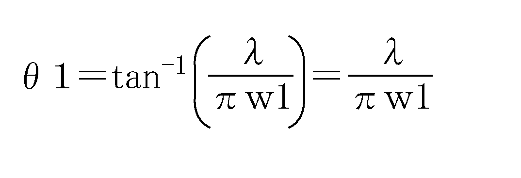
この式によれば、入射されるレーザービームのビームウェストw1が分かれば広がり角θ1を求めることができる。また、ファイバの受光角θ2は、

に示されるとおり、コアの屈折率ncoreとクラッドの屈折率ncladから求められることが分かっている。
に示されるとおり、コアの屈折率ncoreとクラッドの屈折率ncladから求められることが分かっている。
入射されるビームウェストw1が決定されれば、そのビームの広がり角も必然的に決定されるため、ファイバのコアとクラッドの屈折率差はθ2=θ1となるように決定されなければならない。例えば、コアとクラッドに石英ガラスを用いた場合、コアとクラッドの屈折率は1.4~1.6程度の範囲で推移する。
第二部分の中心軸C1方向の長さについて説明する。この長さの違いによる効果を確認するために、光CAE解析を実施した。本検討では第一部分のコア径D1は3μm、第一部分コア8aの屈折率は1.49、第3部分のコア径D3は8.2μm、第三部分コア8cの屈折率は1.4677、ファイバ全長を1000μm、各部分のクラッド(7aと7bと7c)の屈折率は共通で1.4624、入射されたビームのビームウェスト径D7は3.2μmとした。この条件の下で、第二部分の中心軸C1方向の長さを0μmから500μmまで100μm刻みで変化させた場合に、光強度がどのように変化するか計算した。なお、第一部分と第三部分の長さはそれぞれ(1000μm - 第二部分長さ)÷2とした。
この解析の解析結果をまとめたグラフを図10に示す。横軸は第二部分の中心軸C1方向の長さ、縦軸は入射された光を1としたときの、ファイバ出射端における光の強度を対数表示したものである。この解析結果によれば、第二部分の中心軸C1方向の長さが長くなれば、光ファイバ2の内部における損失が小さくなる。その変化の様子としては、0~100μmまでは長さが増加することにより損失は急激に低下し、100μm以上では損失はほぼ横ばいとなる。これより、第二部分の長さは100μm以上であることが望ましいと考えられる。
図11は、本解析条件の一例において、ファイバ内の光強度分布をコンタ図とグラフで示した図である。グラフの縦軸はファイバの入射端からの距離、横軸は光の強度を示している。このグラフで特筆すべきことは、第一部分と第三部分を伝播していく過程において、光はほぼ減衰しないという点である。入射された光は当初光の干渉によって強度が減少するものの、それが出射端からある程度伝播したところで安定する。その後は一定の値を保ったまま第二部分に入る。第二部分ではMFDの変換および屈折率の変化による損失が発生するため光強度は低下し、その後第三部分へと入る。第三部分ではほぼ強度の変化は無く、出射端まで一定の値を保つ。
本発明の一実施形態によれば、第一部分と第三部分の中心軸C1方向の長さは減衰には影響しないため、その長さが変化してもファイバの機能およびファイバ全体の損失には影響は無い。言い換えれば第一部分と第三部分の長さは設計者の任意の長さで設計することができるうえに、その設計寸法の寸法公差は大きくとることができる。この利点はGIファイバやレンズ付ファイバのように厳密な寸法精度を必要とせず、量産性の向上に大きく貢献することができる。
次に、中心軸C1方向に沿った第一部分の長さ、及び中心軸C1方向に沿った第三部分の長さに関する検討について、説明する。
図12(a)~図12(c)は、第一部分の長さに関する検討に用いた参考例の光レセプタクル及びその解析結果の一例を例示する模式図である。
図12(a)~図12(c)は、第一部分の長さに関する検討に用いた参考例の光レセプタクル及びその解析結果の一例を例示する模式図である。
参考例の光レセプタクルは、図12(a)に示すファイバスタブ49を有する。参考例のファイバスタブ49の構造は、実施形態に係るファイバスタブ4において第1の部分21(第一部分クラッド7aと第一部分コア8a)が設けられない構造と同様である。
すなわち、ファイバスタブ49は、光ファイバ29と、光ファイバ29を保持するフェルール39と、を有する。ファイバスタブ49は、プラグフェルールと接続される端面39bと、端面39bとは反対側の端面39aと、を有する。また、光ファイバ29は、第二部分229(変換部)と、第三部分239と、を有する。第三部分239は、第二部分229と軸方向において並び、第二部分229と連続する。第二部分229は、端面39aの一部を形成し、第三部分239は、端面39bの一部を形成する。中心軸C1方向において、第二部分229のコア径は、第三部分239へ向かって拡大している。第三部分239のコア径は、中心軸C1方向において、実質的に一定である。なお、図12(a)では、便宜上、弾性部材など一部の要素を省略している。
すなわち、ファイバスタブ49は、光ファイバ29と、光ファイバ29を保持するフェルール39と、を有する。ファイバスタブ49は、プラグフェルールと接続される端面39bと、端面39bとは反対側の端面39aと、を有する。また、光ファイバ29は、第二部分229(変換部)と、第三部分239と、を有する。第三部分239は、第二部分229と軸方向において並び、第二部分229と連続する。第二部分229は、端面39aの一部を形成し、第三部分239は、端面39bの一部を形成する。中心軸C1方向において、第二部分229のコア径は、第三部分239へ向かって拡大している。第三部分239のコア径は、中心軸C1方向において、実質的に一定である。なお、図12(a)では、便宜上、弾性部材など一部の要素を省略している。
一般に、端面39aは、鏡面状に研磨される。また、端面39bは、凸球面状に研磨される。これにより、端面39a、39bにおける光の損失を抑制することができる。光レセプタクルにおいては、光学素子と光レセプタクルとの接続(例えばV形状の溝が用いられる)や、付着した接着剤の除去の観点からも端面を研磨することが望ましい。
端面39aの研磨量は、例えば5μm以上50μm以下である。これにより、鏡面状の端面を形成することができる。
端面39aの研磨量は、例えば5μm以上50μm以下である。これにより、鏡面状の端面を形成することができる。
ここで、図12(a)に示したファイバスタブ49において、例えば、端面39aが5~50μm程度研磨されると、研磨量に応じて、第二部分229の長さが短くなる。言い換えれば、研磨量に応じて、第二部分229の端面位置(第二部分229のうち端面39aの一部として露出する部分の位置)が5~50μm程度変動する。つまり、端面39aにおけるコア径Daが変動する。これは、GIファイバなど、周期的にMFDが変化するようなファイバを用いる場合には、損失の原因となる。
本願発明者は、上記のような端面39aの研磨と、損失と、の関係について解析を行った。図12(b)及び図12(c)に解析結果の一例を示す。この検討では、端面39aの研磨前において、第二部分229の軸方向に沿った長さLaを50μmとし、端面39aにおけるコア径Daを3μmとし、端面39bにおけるコア径Dbを9μmとした。第二部分229におけるコア径の軸方向に沿った変化率は、一定とした。
図12(b)は、上記のようなファイバスタブ49において、端面39aの研磨により、長さLaが20%(研磨量10μm)、40%(研磨量20μm)、60%(研磨量30μm)又は80%(研磨量40μm)短くなった場合の損失(dB)を表す。図12(c)は、図12(b)のデータを表すグラフ図である。ここで、損失(dB)は、端面39aから光(径DL=3μm)が入射した場合の出射端(端面39b)における光の強度から算出される。
端面39aの研磨が行われる前において損失は、-1.06dBである。グラフより、研磨によって第二部分229が短くなると損失が大きくなることが分かる。例えば、研磨によって変換部(第二部分229)が50%短くなると損失は、-3dB程度となる。
このように、第一部分が設けられない参考例においては、端面を研磨することによって損失が増大してしまう。また、参考例において、予め研磨量を考慮して研磨前の端面のコア径を定めたとしても、研磨量のばらつきに応じて損失がばらつく。研磨量を厳密に管理する必要が生じ、量産性が低下することがある。
これに対して、実施形態に係る光レセプタクルにおいては、実質的にコア径及び屈折率が中心軸C1に沿って変化しない第一部分が設けられる。端面3aの研磨によって、中心軸C1に沿った第一部分の長さが変動しても、光学的損失の増大やばらつきの変化は小さい。例えば、第一部分の長さの範囲内で端面位置が変化しても、光レセプタクルの特性は、実質的に劣化しない。
以上により、第一部分の中心軸C1に沿った長さは、端面3aの研磨量以上であることが望ましい。上述の通り、端面3aを鏡面状とするため、端面3aは、5μm以上50μm以下程度研磨される。したがって、第一部分の中心軸C1に沿った長さは、5μm以上であることが望ましく、可能であれば50μm以上であることが、さらに望ましい。第一部分の中心軸C1に沿った長さの上限は、ファイバスタブ4内(フェルール3の貫通孔内)に第二部分及び第三部分を配設することができれば、特に制限されない。そのためファイバスタブ4の全長によっては、第一部分を7~10mm程度にまで伸ばしてもよい。これにより、量産性を向上させることができる。
図12(a)~図12(c)に関する説明は、例えば、第三部分を有さない参考例においても、同様である。すなわち、この場合は、プラグフェルールと接続される端面におけるコア径が、研磨量によって変化する。端面におけるコア径の変化によって、損失が増大する。これに対して、実施形態に係る光レセプタクルにおいては、実質的にコア径及び屈折率が中心軸C1に沿って変化しない第三部分が設けられる。端面3bの研磨によって、中心軸C1に沿った第三部分の長さが変動しても、光学的損失の増大やばらつきの変化は小さい。
以上により、第三部分の中心軸C1に沿った長さは、端面3bの研磨量以上であることが望ましい。例えば、端面3bを凸球面状とするため、端面3bは、5μm以上20μm以下程度研磨される。したがって、第三部分の中心軸C1に沿った長さは、5μm以上であることが望ましく、可能であれば20μm以上であることが、さらに望ましい。第三部分の中心軸C1に沿った長さの上限は、ファイバスタブ4内(フェルール3の貫通孔内)に第一部分及び第二部分を配設することばできれば、特に制限されない。そのためファイバスタブ4の全長によっては、第三部分を7~10mm程度にまで伸ばしてもよい。これにより、量産性を向上させることができる。
以上説明したように、本実施形態によればファイバスタブ4の凸球面に研磨した端面3bとは反対側の端面3aにおけるコア径D1が凸球面に研磨した端面3bのコア径D2よりも小さいため、光モジュールの長さを小さくすることができる。また、第一部分と第三部分の軸方向長さに対して、高い精度の寸法管理を必要としないものとできる。
第二部分のファイバ外径D5はクラッドの貫通孔3cよりも小さいため、その隙間に弾性部材9が充填されることにより、ファイバが中心軸方向に移動することを抑止することができる。
第二部分のファイバ外径D5はクラッドの貫通孔3cよりも小さいため、その隙間に弾性部材9が充填されることにより、ファイバが中心軸方向に移動することを抑止することができる。
(第三の実施形態)
図13は、本発明の第三の実施形態に係る光レセプタクルの一部を例示する模式的断面図である。
図13は、本実施形態に係る光レセプタクルのうち、ファイバスタブ4の部分を拡大して表している。図13に表したように、第一部分(第1の部分21)は、フェルール3の貫通孔3c内に配置された部分(内側部21a)と、貫通孔3c外に配置された部分(突出部21b)と、を有する。また、本実施形態に係る光レセプタクルは、弾性部材19を有する。上記以外については、本実施形態は、第一又は第二の実施形態と同様である。
図13は、本発明の第三の実施形態に係る光レセプタクルの一部を例示する模式的断面図である。
図13は、本実施形態に係る光レセプタクルのうち、ファイバスタブ4の部分を拡大して表している。図13に表したように、第一部分(第1の部分21)は、フェルール3の貫通孔3c内に配置された部分(内側部21a)と、貫通孔3c外に配置された部分(突出部21b)と、を有する。また、本実施形態に係る光レセプタクルは、弾性部材19を有する。上記以外については、本実施形態は、第一又は第二の実施形態と同様である。
突出部21bは、フェルール3(端面3bとは反対側の、フェルール3の面)から外側に突出している。すなわち、突出部21bは、中心軸C1と直交する方向においてフェルール3と並ばない。内側部21aは、中心軸C1と直交する方向においてフェルール3と並び、中心軸C1に沿って見たときにフェルール3に囲まれている。
また、第二部分の全域および第三部分の全域は、それぞれ貫通孔3c内に配置されている。すなわち、第二部分の全域および第三部分の全域は、中心軸C1と直交する方向においてフェルール3と並び、中心軸C1に沿って見たときにフェルール3に囲まれている。
既に述べたとおり、光レセプタクルの端面3bと反対側には、半導体レーザ素子等のモジュールや光学素子が設けられる。図13には、一例として、光学素子の一部分31を示している。
例えば、光学素子の一部分31は、突出部21bに対応した形状(溝など)を有している。光学素子と光レセプタクルとを組み立てる際には、光学素子の一部分31に突出部21bを載せる等し、光学素子の光出射端に、直接、押し当てる。または、レンズ等の素子を用いて光出射端から突出部21に光が入射されるようにする。これにより、組立の際の調芯の手間を軽減することができる。また、調芯の精度を向上させることができ、光学的な接続損失を低減させることができる。
弾性部材19は、突出部21bの第三部分側の端部に設けられる。弾性部材19は、例えば、突出部21b及びフェルール3に接している。これにより、弾性部材19は、第一部分を保護する。弾性部材19の中心軸C1方向に沿った長さL1は、例えば2mm程度である。このため、突出部21bの中心軸C1方向に沿った長さL2は、2mm以上であることが望ましい。また、第一部分の強度の確保、及び光レセプタクルの小型化の観点から、突出部21bの長さL2は、20mm以下であることが望ましい。なお、第二部分及び第三部分は、貫通孔3cの内部に配置されているため、フェルール3によって保護される。
(第四の実施形態)
図14(a)及び図14(b)は、本発明の第四の実施形態に係る光トランシーバを例示する模式図である。
図14(a)に表したように、本実施形態に係る光トランシーバ200は、光レセプタクル1と、光学素子110と、制御基板120と、を有する。
図14(a)及び図14(b)は、本発明の第四の実施形態に係る光トランシーバを例示する模式図である。
図14(a)に表したように、本実施形態に係る光トランシーバ200は、光レセプタクル1と、光学素子110と、制御基板120と、を有する。
制御基板120上には、回路等が形成されている。制御基板120は、光学素子110と電気的に接続されている。制御基板120は、光学素子110の動作を制御する。
光学素子110は、例えば、受光素子または発光素子が用いられる。この例では、光学素子110は、発光部である。光学素子110は、レーザダイオード111とレンズ112とを有する。レーザダイオード111は、制御基板120に制御され、光を光レセプタクル1のファイバスタブ4へ出射する。レンズ112は、出射された光の光路上において、光レセプタクル1とレーザダイオード111との間に位置する。
なお、光学素子110は、図14(b)に表したように、素子113を有していてもよい。この素子113は、レーザダイオードと、コア径の小さい光導波路と、を有する。導波路のコア内を伝搬する光は、レンズ112を介して光レセプタクル1に入射する。光導波路は、例えば、シリコンフォトニクスによって形成される。また、光導波路には、石英導波路を用いてもよい。なお、実施形態においては、レンズ112を設けずに、レーザダイオードや光導波路から出射される光を直接、光レセプタクル1に入射させてもよい。
また、光レセプタクル1には、プラグフェルール50が挿入されている。プラグフェルール50は、スリーブ6によって保持されている。光ファイバ2は、端面3bにおいて、プラグフェルール50と光学的に接続されている。これにより、光学素子110とプラグフェルール50とが光レセプタクルを介して光学的に接続され、光通信が可能となる。
以上、本発明の実施の形態について説明した。しかし、本発明はこれらの記述に限定されるものではない。前述の実施の形態に関して、当業者が適宜設計変更を加えたものも、本発明の特徴を備えている限り、本発明の範囲に包含される。例えば、ファイバスタブ4などが備える各要素の形状、寸法、材質、配置などや光ファイバ2やフェルール3の設置形態などは、例示したものに限定されるわけではなく適宜変更することができる。
また、前述した各実施の形態が備える各要素は、技術的に可能な限りにおいて組み合わせることができ、これらを組み合わせたものも本発明の特徴を含む限り本発明の範囲に包含される。
また、前述した各実施の形態が備える各要素は、技術的に可能な限りにおいて組み合わせることができ、これらを組み合わせたものも本発明の特徴を含む限り本発明の範囲に包含される。
本発明の態様によれば、光ファイバの光学素子側端面のコアを小さくすることで光モジュール全長を短くすることに貢献しながら、ファイバの軸方向長さに関して高い精度の寸法公差を必要とせず、ファイバの軸方向の動きを抑制することで結合効率の低下を防止し、またMFD変換の損失を抑えることのできる光レセプタクル及び光トランシーバが提供される。
1 光レセプタクル、
2 光ファイバ、
2a 光ファイバの端面、
3 フェルール、
3a 光学素子と光学接続される端面、
3b プラグフェルールと光学接続される端面、
3c 貫通孔、
4 ファイバスタブ、
5 保持具、
6 スリーブ、
7a 第一部分クラッド、
7b 第二部分クラッド、
7c 第三部分クラッド、
8a 第一部分コア、
8b 第二部分コア、
8c 第三部分コア、
9、19 弾性部材、
21 第1の部分、
21a 内側部、
21b 突出部、
22 第2の部分、
23 第3の部分、
29 光ファイバ、
31 光学素子の一部分、
39 フェルール、
39a 光学素子と光学接続される端面、
39b プラグフェルールと光学接続される端面、
49 ファイバスタブ、
50 プラグフェルール、
110 光学素子、
111 レーザダイオード、
112 レンズ、
113 素子、
120 制御基板、
229 第二部分、
239 第三部分、
D1 第一部分のコア径、
D2 第二部分のコア径、
D3 第二部分のコア径、
D4 第一部分のファイバ外径、
D5 第二部分のファイバ外径、
D6 第三部分のファイバ外径、
D7 ビームウェスト径、
C1 ファイバスタブ4の中心軸、
L1 弾性部材の長さ、
L2 突出部の長さ、
S1 部分、
α 広がり角、
α’ 第二部分の境界とビームが織り成す角度
2 光ファイバ、
2a 光ファイバの端面、
3 フェルール、
3a 光学素子と光学接続される端面、
3b プラグフェルールと光学接続される端面、
3c 貫通孔、
4 ファイバスタブ、
5 保持具、
6 スリーブ、
7a 第一部分クラッド、
7b 第二部分クラッド、
7c 第三部分クラッド、
8a 第一部分コア、
8b 第二部分コア、
8c 第三部分コア、
9、19 弾性部材、
21 第1の部分、
21a 内側部、
21b 突出部、
22 第2の部分、
23 第3の部分、
29 光ファイバ、
31 光学素子の一部分、
39 フェルール、
39a 光学素子と光学接続される端面、
39b プラグフェルールと光学接続される端面、
49 ファイバスタブ、
50 プラグフェルール、
110 光学素子、
111 レーザダイオード、
112 レンズ、
113 素子、
120 制御基板、
229 第二部分、
239 第三部分、
D1 第一部分のコア径、
D2 第二部分のコア径、
D3 第二部分のコア径、
D4 第一部分のファイバ外径、
D5 第二部分のファイバ外径、
D6 第三部分のファイバ外径、
D7 ビームウェスト径、
C1 ファイバスタブ4の中心軸、
L1 弾性部材の長さ、
L2 突出部の長さ、
S1 部分、
α 広がり角、
α’ 第二部分の境界とビームが織り成す角度
Claims (22)
- 光を導通するためのコアとクラッドを有する光ファイバ、前記光ファイバが固定される貫通孔を有するフェルール、前記光ファイバを前記貫通孔に固定する弾性部材、を含むファイバスタブと、
前記ファイバスタブを保持する保持具と、
を備え、
前記ファイバスタブは、前記フェルールのプラグフェルールと光学的接続する側の一端面と、前記一端面とは反対側の他端面を有し、
前記光ファイバは、前記他端面側の第1の部分と、前記一端面側の第3の部分と、前記
第1の部分と前記第3の部分との間に第2の部分を有し、
前記第1の部分におけるコア径は、前記第3の部分におけるコア径より小さく、
前記第2の部分におけるコア径は、前記第1の部分側から前記第3の部分側に向かって大きくなり、
前記弾性部材は、前記光ファイバと前記貫通孔の内壁との間の空間に充填されたことを特徴とする光レセプタクル。 - 前記第1の部分のコアの屈折率、前記第2の部分のコアの屈折率、および前記第3の部分におけるコアの屈折率は、互いに等しく、
前記第1の部分のクラッドの屈折率は、前記第3の部分のクラッドの屈折率より小さく、
前記第2の部分のクラッドの屈折率は、前記第1の部分側から前記第3の部分側に向かって大きくなることを特徴とする請求項1に記載の光レセプタクル。 - 前記第1の部分のクラッドの屈折率、前記第2の部分のクラッドの屈折率、および前記第3の部分におけるクラッドの屈折率は、互いに等しく、
前記第1の部分のコアの屈折率は、前記第3の部分のコアの屈折率より大きく、
前記第2の部分のコアの屈折率は、前記第1の部分側から前記第3の部分側に向かって小さくなることを特徴とする請求項1に記載の光レセプタクル。 - 前記第2の部分のコア径は、前記第1の部分側から前記第3の部分側に向かって線形に大きくなることを特徴とする請求項1~3のいずれか1つに記載の光レセプタクル。
- 前記第2の部分のコア径は、前記第1の部分側から前記第3の部分側に向かって非線形に大きくなることを特徴とする請求項1~3のいずれか1つに記載の光レセプタクル。
- 前記第2の部分のコアは、前記第1の部分側から前記第3の部分側にかけて、前記第2の部分のコア径が大きくなっている領域の一部に段差を有することを特徴とする請求項1~3のいずれか1つに記載の光レセプタクル。
- 前記第1の部分におけるコア径が、0.5μm以上、8μm以下であることを特徴とする請求項1~6のいずれか1つに記載の光レセプタクル。
- 前記第1の部分におけるコアの屈折率とクラッドの屈折率との差は、前記第3の部分におけるコアの屈折率とクラッドの屈折率との差より大きいことを特徴とする請求項1~7のいずれか1つに記載の光レセプタクル。
- 前記第1の部分におけるコアの屈折率とクラッドの屈折率との差は、前記第2の部分におけるコアの屈折率とクラッドの屈折率との差より大きいことを特徴とする請求項1~8のいずれか1つに記載の光レセプタクル。
- 前記第3の部分におけるコア径が、8μm以上、20μm以下であることを特徴とする請求項1~9のいずれか1つに記載の光レセプタクル。
- 前記第3の部分におけるコアの屈折率とクラッドの屈折率との差は、前記第2の部分におけるコアの屈折率とクラッドの屈折率との差より小さいことを特徴とする請求項1~10のいずれか1つに記載の光レセプタクル。
- 前記第2の部分におけるコアの屈折率とクラッドの屈折率の差は、前記第1の部分側から前記第3の部分側に向かって小さくなることを特徴とする請求項1~11のいずれか1つに記載の光レセプタクル。
- 前記第1の部分における前記光ファイバの外径は、前記第3の部分における前記光ファイバの外径と等しいことを特徴とする請求項1~12のいずれか1つに記載の光レセプタクル。
- 前記第2の部分における前記光ファイバの外径は、前記第1の部分における前記光ファイバの外径よりも小さいことを特徴とする請求項1~13のいずれか1つに記載の光レセプタクル。
- 前記第2の部分における前記光ファイバの外径は、前記第3の部分における前記光ファイバの外径よりも小さいことを特徴とする請求項1~14のいずれか1つに記載の光レセプタクル。
- 前記第1の部分、前記第2の部分、および前記第3の部分は、全域に渡って前記貫通孔内に配設されていることを特徴とする請求項1~15のいずれか1つに記載の光レセプタクル。
- 前記第1の部分は、前記フェルールから突出した部分を有し、
前記第2の部分及び前記第3の部分は、全域に亘って前記貫通孔内に配設されていることを特徴とする請求項1~15のいずれか1つに記載の光レセプタクル。 - 前記ファイバスタブのプラグフェルールと光学的接続する側とは反対側の端面において、前記フェルールの端面の一部と前記光ファイバの端面が、前記ファイバスタブの中心軸に対して垂直となる面から所定の角度をもつことを特徴とする請求項1~17のいずれか1つに記載の光レセプタクル。
- 前記第1の部分、前記第2の部分、および前記第3の部分は、一体でできていることを特徴とする請求項1~18のいずれか1つに記載の光レセプタクル。
- 前記ファイバスタブの中心軸に沿った前記第1の部分の長さは、5μm以上であることを特徴とする請求項1~19のいずれか1つに記載の光レセプタクル。
- 前記ファイバスタブの中心軸に沿った前記第3の部分の長さは、5μm以上であることを特徴とする請求項1~20のいずれか1つに記載の光レセプタクル。
- 請求項1~21のいずれか1つに記載の光レセプタクルを備えたことを特徴とする光トランシーバ。
Priority Applications (2)
| Application Number | Priority Date | Filing Date | Title |
|---|---|---|---|
| CN201580066559.7A CN107003488B (zh) | 2014-12-26 | 2015-12-24 | 光插座及光收发器 |
| US15/632,973 US10180546B2 (en) | 2014-12-26 | 2017-06-26 | Optical receptacle and optical transceiver |
Applications Claiming Priority (6)
| Application Number | Priority Date | Filing Date | Title |
|---|---|---|---|
| JP2014265175 | 2014-12-26 | ||
| JP2014-265175 | 2014-12-26 | ||
| JP2015156333A JP6170527B2 (ja) | 2014-12-26 | 2015-08-06 | 光レセプタクル及び光トランシーバ |
| JP2015-156333 | 2015-08-06 | ||
| JP2015-250459 | 2015-12-22 | ||
| JP2015250459A JP2016126339A (ja) | 2014-12-26 | 2015-12-22 | 光レセプタクル及び光トランシーバ |
Related Child Applications (1)
| Application Number | Title | Priority Date | Filing Date |
|---|---|---|---|
| US15/632,973 Continuation US10180546B2 (en) | 2014-12-26 | 2017-06-26 | Optical receptacle and optical transceiver |
Publications (1)
| Publication Number | Publication Date |
|---|---|
| WO2016104653A1 true WO2016104653A1 (ja) | 2016-06-30 |
Family
ID=56150666
Family Applications (1)
| Application Number | Title | Priority Date | Filing Date |
|---|---|---|---|
| PCT/JP2015/086113 Ceased WO2016104653A1 (ja) | 2014-12-26 | 2015-12-24 | 光レセプタクル及び光トランシーバ |
Country Status (2)
| Country | Link |
|---|---|
| CN (1) | CN110646895B (ja) |
| WO (1) | WO2016104653A1 (ja) |
Cited By (1)
| Publication number | Priority date | Publication date | Assignee | Title |
|---|---|---|---|---|
| US20190212501A1 (en) * | 2017-03-30 | 2019-07-11 | Toto Ltd. | Optical receptacle and optical transceiver |
Citations (2)
| Publication number | Priority date | Publication date | Assignee | Title |
|---|---|---|---|---|
| JP2006030366A (ja) * | 2004-07-13 | 2006-02-02 | Totoku Electric Co Ltd | Mfd変換アダプタ |
| JP2006119633A (ja) * | 2004-09-27 | 2006-05-11 | Kyocera Corp | 光レセプタクルおよびこれを用いた光モジュール |
Family Cites Families (10)
| Publication number | Priority date | Publication date | Assignee | Title |
|---|---|---|---|---|
| US5113474A (en) * | 1990-03-13 | 1992-05-12 | Optical Fiber Technologies, Inc. | Method and apparatus for mechanical connector assembly |
| JPH06180406A (ja) * | 1992-12-14 | 1994-06-28 | Furukawa Electric Co Ltd:The | 光ファイバの接続方法 |
| JPH0713036A (ja) * | 1993-06-15 | 1995-01-17 | Hitachi Cable Ltd | ピッグテールファイバ付光デバイス及びその製造方法 |
| JPH08201642A (ja) * | 1995-01-25 | 1996-08-09 | Fujitsu Ltd | 光ファイバの接続方法及び装置並びに補強構造 |
| JP2002040294A (ja) * | 2000-07-21 | 2002-02-06 | Ykk Corp | 光コネクタ部品の光ファイバ挿入孔内に接着剤を注入する方法及び装置 |
| JP2003255182A (ja) * | 2002-02-28 | 2003-09-10 | Fujikura Ltd | フェルールの製造方法およびフェルール用母材 |
| JP2005208113A (ja) * | 2004-01-20 | 2005-08-04 | Nippon Telegr & Teleph Corp <Ntt> | モードフィールド変換器 |
| JP3974592B2 (ja) * | 2004-02-24 | 2007-09-12 | 日本電信電話株式会社 | 単心光コネクタの組立方法及びその組立工具 |
| US20070196053A1 (en) * | 2006-02-17 | 2007-08-23 | Anthony Kewitsch | Isolated Fiber Optic Union Adapters |
| JP2008032993A (ja) * | 2006-07-28 | 2008-02-14 | Kyocera Corp | 光ファイバ体およびこれを用いたモード変換器 |
-
2015
- 2015-12-24 CN CN201910789095.2A patent/CN110646895B/zh active Active
- 2015-12-24 WO PCT/JP2015/086113 patent/WO2016104653A1/ja not_active Ceased
Patent Citations (2)
| Publication number | Priority date | Publication date | Assignee | Title |
|---|---|---|---|---|
| JP2006030366A (ja) * | 2004-07-13 | 2006-02-02 | Totoku Electric Co Ltd | Mfd変換アダプタ |
| JP2006119633A (ja) * | 2004-09-27 | 2006-05-11 | Kyocera Corp | 光レセプタクルおよびこれを用いた光モジュール |
Cited By (1)
| Publication number | Priority date | Publication date | Assignee | Title |
|---|---|---|---|---|
| US20190212501A1 (en) * | 2017-03-30 | 2019-07-11 | Toto Ltd. | Optical receptacle and optical transceiver |
Also Published As
| Publication number | Publication date |
|---|---|
| CN110646895B (zh) | 2021-12-28 |
| CN110646895A (zh) | 2020-01-03 |
Similar Documents
| Publication | Publication Date | Title |
|---|---|---|
| JP6170527B2 (ja) | 光レセプタクル及び光トランシーバ | |
| JP5952326B2 (ja) | 光レセプタクル | |
| US7415179B2 (en) | Optical fiber connector body with mutually coaxial and inclined cores, optical connector for forming the same, and mode conditioner and optical transmitter using the same | |
| JP2022065147A (ja) | 光レセプタクル及び光トランシーバ | |
| JP2017054110A (ja) | 光モジュール | |
| JP7107194B2 (ja) | 光接続構造 | |
| JP7213499B2 (ja) | 光結合器 | |
| US20210026080A1 (en) | Optical receptacle and optical transceiver | |
| US20190033534A1 (en) | Optical fiber connector, optical apparatus, optical transceiver, and method of manufacturing optical fiber connector | |
| JP2015028593A (ja) | 光レセプタクル | |
| CN110646895B (zh) | 光插座及光收发器 | |
| CN107735705A (zh) | 用于使激光二极管与光纤光学耦合的光学耦合系统 | |
| WO2018003940A1 (ja) | 光レセプタクル及び光トランシーバ | |
| US20130064553A1 (en) | Optical communication module and optical communication apparatus | |
| US20210124138A1 (en) | Light source device | |
| JPWO2007043558A1 (ja) | 光レセプタクル、光モジュール及び光レセプタクルにおける結合効率のばらつき低減方法 | |
| JP2005227414A (ja) | 光接続デバイス | |
| JP2015096978A (ja) | 光レセプタクル | |
| WO2014016939A1 (ja) | 発光素子・光ファイバ結合モジュール及びその部品 |
Legal Events
| Date | Code | Title | Description |
|---|---|---|---|
| 121 | Ep: the epo has been informed by wipo that ep was designated in this application |
Ref document number: 15873221 Country of ref document: EP Kind code of ref document: A1 |
|
| NENP | Non-entry into the national phase |
Ref country code: DE |
|
| 122 | Ep: pct application non-entry in european phase |
Ref document number: 15873221 Country of ref document: EP Kind code of ref document: A1 |