WO2016104638A1 - 磁気共鳴イメージング装置及び磁気共鳴イメージング装置の設置方法 - Google Patents
磁気共鳴イメージング装置及び磁気共鳴イメージング装置の設置方法 Download PDFInfo
- Publication number
- WO2016104638A1 WO2016104638A1 PCT/JP2015/086088 JP2015086088W WO2016104638A1 WO 2016104638 A1 WO2016104638 A1 WO 2016104638A1 JP 2015086088 W JP2015086088 W JP 2015086088W WO 2016104638 A1 WO2016104638 A1 WO 2016104638A1
- Authority
- WO
- WIPO (PCT)
- Prior art keywords
- resonance imaging
- magnetic resonance
- imaging apparatus
- unit
- board
- Prior art date
- Legal status (The legal status is an assumption and is not a legal conclusion. Google has not performed a legal analysis and makes no representation as to the accuracy of the status listed.)
- Ceased
Links
Images



Classifications
-
- G—PHYSICS
- G01—MEASURING; TESTING
- G01R—MEASURING ELECTRIC VARIABLES; MEASURING MAGNETIC VARIABLES
- G01R33/00—Arrangements or instruments for measuring magnetic variables
- G01R33/20—Arrangements or instruments for measuring magnetic variables involving magnetic resonance
- G01R33/28—Details of apparatus provided for in groups G01R33/44 - G01R33/64
- G01R33/38—Systems for generation, homogenisation or stabilisation of the main or gradient magnetic field
- G01R33/3802—Manufacture or installation of magnet assemblies; Additional hardware for transportation or installation of the magnet assembly or for providing mechanical support to components of the magnet assembly
-
- G—PHYSICS
- G01—MEASURING; TESTING
- G01R—MEASURING ELECTRIC VARIABLES; MEASURING MAGNETIC VARIABLES
- G01R33/00—Arrangements or instruments for measuring magnetic variables
- G01R33/20—Arrangements or instruments for measuring magnetic variables involving magnetic resonance
- G01R33/28—Details of apparatus provided for in groups G01R33/44 - G01R33/64
- G01R33/32—Excitation or detection systems, e.g. using radio frequency signals
- G01R33/34—Constructional details, e.g. resonators, specially adapted to MR
- G01R33/34007—Manufacture of RF coils, e.g. using printed circuit board technology; additional hardware for providing mechanical support to the RF coil assembly or to part thereof, e.g. a support for moving the coil assembly relative to the remainder of the MR system
-
- A—HUMAN NECESSITIES
- A61—MEDICAL OR VETERINARY SCIENCE; HYGIENE
- A61B—DIAGNOSIS; SURGERY; IDENTIFICATION
- A61B5/00—Measuring for diagnostic purposes; Identification of persons
- A61B5/05—Detecting, measuring or recording for diagnosis by means of electric currents or magnetic fields; Measuring using microwaves or radio waves
- A61B5/055—Detecting, measuring or recording for diagnosis by means of electric currents or magnetic fields; Measuring using microwaves or radio waves involving electronic [EMR] or nuclear [NMR] magnetic resonance, e.g. magnetic resonance imaging
-
- A—HUMAN NECESSITIES
- A61—MEDICAL OR VETERINARY SCIENCE; HYGIENE
- A61B—DIAGNOSIS; SURGERY; IDENTIFICATION
- A61B5/00—Measuring for diagnostic purposes; Identification of persons
- A61B5/70—Means for positioning the patient in relation to the detecting, measuring or recording means
- A61B5/704—Tables
-
- G—PHYSICS
- G01—MEASURING; TESTING
- G01R—MEASURING ELECTRIC VARIABLES; MEASURING MAGNETIC VARIABLES
- G01R33/00—Arrangements or instruments for measuring magnetic variables
- G01R33/20—Arrangements or instruments for measuring magnetic variables involving magnetic resonance
- G01R33/28—Details of apparatus provided for in groups G01R33/44 - G01R33/64
- G01R33/30—Sample handling arrangements, e.g. sample cells, spinning mechanisms
-
- G—PHYSICS
- G01—MEASURING; TESTING
- G01R—MEASURING ELECTRIC VARIABLES; MEASURING MAGNETIC VARIABLES
- G01R33/00—Arrangements or instruments for measuring magnetic variables
- G01R33/20—Arrangements or instruments for measuring magnetic variables involving magnetic resonance
- G01R33/28—Details of apparatus provided for in groups G01R33/44 - G01R33/64
- G01R33/32—Excitation or detection systems, e.g. using radio frequency signals
- G01R33/36—Electrical details, e.g. matching or coupling of the coil to the receiver
- G01R33/3614—RF power amplifiers
-
- G—PHYSICS
- G01—MEASURING; TESTING
- G01R—MEASURING ELECTRIC VARIABLES; MEASURING MAGNETIC VARIABLES
- G01R33/00—Arrangements or instruments for measuring magnetic variables
- G01R33/20—Arrangements or instruments for measuring magnetic variables involving magnetic resonance
- G01R33/44—Arrangements or instruments for measuring magnetic variables involving magnetic resonance using nuclear magnetic resonance [NMR]
- G01R33/48—NMR imaging systems
- G01R33/54—Signal processing systems, e.g. using pulse sequences ; Generation or control of pulse sequences; Operator console
- G01R33/543—Control of the operation of the MR system, e.g. setting of acquisition parameters prior to or during MR data acquisition, dynamic shimming, use of one or more scout images for scan plane prescription
-
- G—PHYSICS
- G01—MEASURING; TESTING
- G01R—MEASURING ELECTRIC VARIABLES; MEASURING MAGNETIC VARIABLES
- G01R33/00—Arrangements or instruments for measuring magnetic variables
- G01R33/20—Arrangements or instruments for measuring magnetic variables involving magnetic resonance
- G01R33/28—Details of apparatus provided for in groups G01R33/44 - G01R33/64
- G01R33/32—Excitation or detection systems, e.g. using radio frequency signals
- G01R33/36—Electrical details, e.g. matching or coupling of the coil to the receiver
-
- G—PHYSICS
- G01—MEASURING; TESTING
- G01R—MEASURING ELECTRIC VARIABLES; MEASURING MAGNETIC VARIABLES
- G01R33/00—Arrangements or instruments for measuring magnetic variables
- G01R33/20—Arrangements or instruments for measuring magnetic variables involving magnetic resonance
- G01R33/28—Details of apparatus provided for in groups G01R33/44 - G01R33/64
- G01R33/42—Screening
- G01R33/422—Screening of the radio frequency field
Definitions
- Embodiments described herein relate generally to a magnetic resonance imaging apparatus and a method for installing the magnetic resonance imaging apparatus.
- Magnetic resonance imaging (MRI) apparatuses are widely used in the field of medical image diagnosis.
- MRI is an imaging method based on a magnetic resonance phenomenon, in which an atomic nucleus (such as 1 H) spin of a subject placed in a space in which a static magnetic field is formed is converted into a Larmor frequency RF (RF: radio frequency) signal.
- RF Larmor frequency
- This is an imaging method in which an image is reconstructed from a nuclear magnetic resonance (NMR) signal that is magnetically excited by and excited with the excitation.
- NMR nuclear magnetic resonance
- various units such as a host computer and power supplies are installed in a room different from a photography room called a machine room. This originates from prevention of noise radiation from the various units and the influence of the static magnetic field formed in the photographing room on the various units.
- An object is to provide a magnetic resonance imaging apparatus and a method for installing the magnetic resonance imaging apparatus that can realize a space-saving installation as compared with the prior art.
- a magnetic resonance imaging apparatus is installed in a shield room and includes a gantry having a static magnetic field magnet, a gradient magnetic field coil, and an RF coil, a bed on which a subject is placed, and the magnetic resonance imaging apparatus. And at least one unit related to control. The at least one unit is provided with an opening for maintenance on the upper surface.
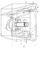
- FIG. 1A is a bird's eye view showing a magnetic resonance imaging apparatus according to the first embodiment and a shield room in which the magnetic resonance imaging apparatus is installed.
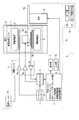
- FIG. 1B is a block diagram illustrating an example of a magnetic resonance imaging system including the magnetic resonance imaging apparatus according to the first embodiment.
- FIG. 1C is a bird's eye view showing a magnetic resonance imaging apparatus according to a modification of the first embodiment and a shield room in which the magnetic resonance imaging apparatus is installed.
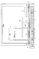
- FIG. 2 is a plan view showing an example of a magnetic resonance imaging system including the magnetic resonance imaging apparatus according to the first embodiment.
- FIG. 3 is a plan view showing a modification including a cooling fan in the magnetic resonance imaging system including the magnetic resonance imaging apparatus according to the first embodiment.
- FIG. 4A is a plan view showing a modified example including a partially detachable floor board in the magnetic resonance imaging system including the magnetic resonance imaging apparatus according to the first embodiment.
- FIG. 4B is a bird's-eye view showing a magnetic resonance imaging apparatus according to a modification of the first embodiment and a shield room in which the magnetic resonance imaging apparatus is installed.
- FIG. 5 is a flowchart illustrating an example of an installation method of the magnetic resonance imaging system including the magnetic resonance imaging apparatus according to the first embodiment.
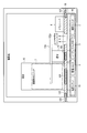
- FIG. 6A is a plan view illustrating an example of a magnetic resonance imaging system including the magnetic resonance imaging apparatus according to the second embodiment.
- FIG. 6B is a bird's-eye view showing the magnetic resonance imaging apparatus according to the second embodiment and a shield room in which the magnetic resonance imaging apparatus is installed.
- FIG. 7 is a flowchart illustrating an example of a method for installing a magnetic resonance imaging system including the magnetic resonance imaging apparatus according to the second embodiment.
- FIG. 1A is a bird's-eye view showing a magnetic resonance imaging apparatus 1a according to the first embodiment, a shield room R1 in which the magnetic resonance imaging apparatus is installed, and the like.
- FIG. 1B is a block diagram illustrating an example of a magnetic resonance imaging system 1 including a magnetic resonance imaging apparatus 1a and a floor board 1b according to the first embodiment.
- a floor board 1b is laid at a predetermined height from the floor surface of the shield room R1.
- the space surrounded by the floor board 1b, the ceiling of the shield room R1, and the side surface (wall) of the shield room forms the photographing room r1.
- the space surrounded by the floor board 1b, the floor surface of the shield room R1, and the wall of the shield room forms the storage room r2.
- the floor board 1b is subjected to a magnetic shielding process and a high-frequency noise shielding (or blocking) process. Therefore, the photographing room r1 and the storage room r2 are electromagnetically shielded.
- the magnetic resonance imaging apparatus 1a includes a control unit 2, a sequence controller 3, a transceiver 4, an amplification unit 5, a gantry 6, a power supply unit 10, a display unit 11, an input unit 12, and a bed 13. First, the configuration and function of each unit will be described.
- the control unit 2 is responsible for overall operation related to the magnetic resonance imaging apparatus 1a.
- the control unit 2 includes, for example, a host computer having a memory, a hard disk, a CPU, and the like, a data collection unit that collects data (electric signals based on NMR signals) transmitted from the transceiver, and reconstructs MR images from the collected data.
- the image reconstruction part to comprise and the bed control part which controls the bed 13 so that adjustment is possible are provided. However, this is not the case. The detailed operation will be described again in connection with the description of other parts.
- the sequence controller 3 is connected to the gradient driver 5a and the transceiver 4 in the amplification unit 5, and transmits an electric signal for generating a gradient magnetic field and generates an RF (more precisely, a magnetic field component of RF) pulse. For controlling the transmission / reception of electric signals (via the transceiver 4). That is, the sequence controller 3 transmits a trigger to the connection destination at a determined timing.
- the transceiver 4 transmits an electrical signal for generating an RF pulse for exciting the atomic nucleus of the subject via the transmitter 5b. Further, the transceiver 4 receives, via the preamplifier 5c, an electrical signal based on the NMR signal that is generated when the nucleus excited by the RF pulse returns to its original state. Further, the transceiver 4 transmits an electrical signal based on the NMR signal to the control unit 2.
- the amplification unit 5 includes a gradient driver 5a (an amplifier that amplifies and transmits an electric signal for generating a gradient magnetic field), a transmitter 5b (an amplifier that amplifies and transmits an electric signal for generating an RF pulse), and a preamplifier 5c (NMR). It is a general term for amplifiers that amplify and transmit electrical signals based on signals.
- the gradient driver 5a transmits an electric signal to the gradient magnetic field coil 9a in synchronization with a trigger from the sequence controller so that the gradient magnetic field coil 9a forms a gradient magnetic field.
- the transmitter 5b transmits an electrical signal to the RF transmission coil 9b in synchronization with the trigger of the transceiver 4.
- the preamplifier 5 c amplifies an electrical signal (weak) based on the NMR signal obtained from the subject via the RF receiving coil 9 c and transmits the electrical signal to the transceiver 4.
- the gantry 6 includes a static magnetic field magnet 8, a gradient magnetic field coil 9a, an RF transmission coil 9b, and an RF reception coil 9c.
- the static magnetic field magnet 8, the gradient magnetic field coil 9a, the RF transmission coil 9b, and the RF reception coil 9c are collectively referred to as a magnetic field forming unit 7.
- the static magnetic field magnet 8 is assumed to be a general superconducting magnet in this embodiment.
- the static magnetic field magnet 8 forms a static magnetic field in the space where the subject is placed.
- the static magnetic field magnet 8 may be a normal conducting magnet or a permanent magnet.
- the gradient coil 9a forms a gradient magnetic field in response to an electric signal input from the gradient driver 5a.
- the gradient coil 9a has three coils corresponding to the three axes of X, Y, and Z. However, in FIG. 1, one definition of the gradient magnetic field coil 9 a is performed in order to prevent complication of the drawing. Due to the gradient magnetic field, the nucleus in the subject has a different Larmor frequency for each position of the nucleus. That is, the position information of the cross section can be distinguished from the NMR signal by the difference in the Larmor frequency.
- the RF transmission coil 9b transmits an RF pulse to the subject in response to an electric signal input from the transmitter 5b.
- the RF pulse excites the subject's nuclei corresponding to the intrinsic Larmor frequency.
- the RF receiving coil 9c receives an NMR signal generated when the atomic nucleus of the subject returns from the excited state to the original state, and transmits an electronic signal (weak) based on the NMR signal to the preamplifier 5c.
- the RF transmission coil 9b and the RF reception coil 9c are separate coils, but may be implemented as the same coil as a modification.
- the power supply unit 10 has a plurality of power supplies, for example, five power supplies, and applies a voltage to each amplifier in the amplification unit (corresponding to the gradient coil 9a, the RF transmission coil 9b, and the RF reception coil 9c each consisting of three coils). To do.
- the display unit 11 is connected to the control unit 2 and displays, for example, a captured MRI image.
- the input unit 12 is connected to the control unit 2 and receives an instruction input from an operator such as a doctor via, for example, a switch button, a mouse, a keyboard, or the like.
- the instruction input is transferred to the host computer in the control unit 2.
- the host computer executes predetermined control and calculation in response to the instruction input. For example, it is assumed that the operator pays attention only to a predetermined region of interest (ROI) in the MRI image displayed on the display unit 11 and wants to enlarge and display the portion.
- the input unit 12 receives an instruction input related to enlargement of the ROI by the operator.
- the instruction input is transferred to the host computer.
- the host computer executes MRI image enlargement processing.
- the display unit 11 displays the MRI image that has been subjected to the enlargement process.
- the bed 13 is installed on the floor surface of the shield room R1, and has an adjustment mechanism (not shown) that can adjust the position of the top plate 13a in the longitudinal direction.
- the bed control unit in the control unit 2 moves the top plate 13 a in the longitudinal direction via the adjustment mechanism, and the subject placement space in which the subject placed on the top plate 13 a is located inside the gantry 6. To place.
- the bed 13 of the magnetic resonance imaging apparatus 1a shown in FIG. 1A does not have a mechanism for adjusting the height of the top board 13a. This is due to the following reason. That is, the floor surface of the photographing room r1 shown in FIG. 1A, that is, the floor board 1b, is installed at a predetermined height from the floor surface of the shield room R1.
- the top plate 13a of the bed 13 is positioned at the height of the bore of the gantry 6 without moving up and down, and at a height at which the subject on the floor board 1b can easily go up and down. For this reason, there is little need to provide the bed 13 with a vertical movement mechanism for the top plate 13a.
- the vertical movement of the top board 13a may give fear to the child.
- the magnetic resonance imaging apparatus 1a shown in FIG. 1A it is not necessary to move the top plate 13a up and down when the subject goes up and down the top plate 13a or guides the subject to the bore of the top plate 13a. Therefore, it is possible to perform photographing safely without giving a physical burden or a psychological burden to the subject.
- the power can be saved.
- the bed 13 having the height adjustment mechanism of the top plate 13a is installed on the floor surface of the shield room R1 as necessary. Also good.
- the floor board 1b forms a floor of the photographing room r1, a board part 100 (for example, a non-metallic plate made of resin, etc.) and a board part fixing jig on which a magnetic-shielding process and a high-frequency noise shielding (or blocking) process are performed. 101 (fixing means).
- the board part fixing jig 101 is a jig for fixing the board part 100 to the magnetic resonance imaging apparatus 1a.
- the jig has, for example, uneven portions and screw holes.
- the magnetic resonance imaging system 1 is mounted by combining the magnetic resonance imaging apparatus 1a and the floor board 1b according to the present embodiment.
- the board part 100 may be supported using a column or a beam.
- the board part 100 does not need to be an integral structure, and may be realized by assembling a plurality of panels.
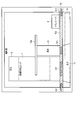
- FIG. 2 is a plan view showing an example of an installation form of the magnetic resonance imaging apparatus 1a according to the first embodiment.
- the gantry 6, the bed 13, the control unit 2, the sequence controller 3, the amplification unit 5, and the power supply unit 10 are placed on the floor surface of the shield room R ⁇ b> 1 (that is, in the storage room r ⁇ b> 2). ing. Since the control unit 2, the sequence controller 3, the amplification unit 5, and the power supply unit 10 may generate high-frequency noise that interferes with the RF frequency band, they are referred to as noise emission units 14 here.
- the board portion 100 of the floor board 1b is fixed to the magnetic resonance imaging apparatus 1a (for example, the gantry 6 and the bed 13 in FIG. 2) and the wall surface of the shield room R1 via the board portion fixing jig 101. .
- the transceiver 4 is placed on the upper surface of the floor board 1b (that is, in the photographing room r1).
- the gantry 6 and the bed 13 are installed on the floor surface of the shield room R1, penetrate the floor board 1b, and are located across both the storage room r2 and the photographing room r1. Therefore, the floor board 1b is processed in advance or during installation in accordance with the shape of the wall 6 of the shield room R1 and the shape of the wall surface of the shield room R1 (the shape of the horizontal section of the shield room R1).
- the board portion 100 of the floor board 1b is subjected to a magnetic-shielding process and a high-frequency noise shielding process. That is, the board part 100 has a magnetic-shielding layer and a high-frequency-proof layer (anti-RF layer).
- the magnetic field forming unit 7 generates a magnetic field for performing magnetic resonance imaging (a static magnetic field by the static magnetic field magnet 8 and a gradient magnetic field by the gradient magnetic field coil 9a).
- the magnetic-shielding layer of the board unit 100 shields the magnetic field, thereby realizing a magnetic field space in the imaging room r1 and not in the storage room r2.
- the noise radiation unit 14 may radiate high-frequency noise (RF noise) having a frequency close to that of RF used for magnetic resonance imaging during its operation. This can occur regardless of whether the various units in the noise radiation unit 14 are connected by a cable or perform wireless communication.
- RF noise high-frequency noise
- the anti-high-frequency layer included in the board unit 100 shields the high-frequency noise, thereby preventing the high-frequency noise from propagating to the first space.
- the floor board 1b also functions as a floor surface of the shooting room r1. Therefore, the doctor and the subject can freely go back and forth on the floor board 1b.
- the gantry 6 is installed on the floor surface of the shield room R1. For this reason, for example, there is leakage of a static magnetic field into the storage room r2 from between the gantry 6 and the floor board 1b, and leakage of high-frequency noise due to the noise radiation unit 14 into the photographing room r1.
- the leakage is weak compared to the case where the floor board 1b is not installed.
- the magnetic-proof and high-frequency-proof property of the mount frame 6 may be strengthened.
- a machine room R2 adjacent to the shield room R1 is provided.
- a desired device or machine among the control unit 2, the sequence controller 3, the amplification unit 5, the power supply unit 10 and other units included in the magnetic resonance imaging apparatus 1a may be installed as necessary.
- the units U1 and U2 are formally described.
- the installation of the machine room R2 is not essential. For example, by installing units U1 and U2 provided in the machine room R2 in the storage room r2, the machine room R2 can be reduced or omitted, and further space saving can be realized.
- the noise radiation unit 14 is installed in the storage room r2, and the magnetic field forming unit 7, the top plate 13a, and the like are installed in the imaging room r1. Further, a predetermined unit U1 or the like of the magnetic resonance imaging apparatus 1a may be installed in the machine room R2 as necessary. Thus, it is necessary to realize the cable wiring between the units arranged in different spaces while maintaining the electromagnetic shielding properties of the shield room R1 and the photographing room r1.
- the predetermined apparatus such as the noise radiation unit 14 installed in the storage room r2 is provided in a double floor structure of the floor of the shield room R1 and the floor board 1b.
- the filter panel (which is a wiring panel having electromagnetic shielding properties, for example, installed in the floor board 1b or the storage room r2 and not shown in FIGS. 1A and 1C) is drawn from the gantry 6 and It is connected to the cable collected at the bottom of the gantry 6.
- a cable drawn from a predetermined device such as the noise radiation unit 14 installed in the storage room r2 or a cable drawn from the gantry 6 and aggregated in the lower part of the gantry 6 is connected between the storage room r2 and the machine room R2. It is connected to a predetermined unit U1 and the like installed in the machine room R2 via a filter panel 200 provided on the wall surface therebetween.
- the cables connecting the units arranged in different spaces can be concentrated in one place while maintaining electromagnetic shielding properties.
- work load can be reduced when performing installation, maintenance, inspection, and the like.
- the noise radiation unit 14 and the like provided in the magnetic resonance imaging apparatus 1a according to the present embodiment and installed in the storage chamber r2 includes various switches, connection terminals, display screens, pilot lamps, and devices arranged on the upper surface thereof. It has an opening for accessing the inside (for maintenance and inspection). According to such a configuration, the operator can easily check the wiring and the inside of each unit from the photographing room r1 side. As a result, the work burden during maintenance and inspection can be greatly reduced.
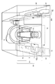
- FIG. 3 is a plan view showing a modification including the cooling fan 16 (cooling mechanism) in the magnetic resonance imaging apparatus 1a according to the first embodiment.
- a vent is provided in a part of the wall between the storage chamber r2 and the outside of the storage chamber r2 (for example, the machine chamber R2).
- a cooling fan 16 is installed in the vicinity of the vent on the outside of the storage chamber r2.
- the cooling fan 16 cools the power supply unit 10 that generates heat, for example, by generating convection in the second space. Since the cooling fan 16 uses a motor, it does not operate in a magnetic field environment. In the modification, for the reason described above, the cooling fan 16 is installed outside the storage room r2 just in case. However, if the magnetic-shielding performance of the board part 100 in the floor board 1b is improved, the cooling fan 16 may be installed in the storage room r2 like the noise radiation unit 14.
- FIG. 4A is a plan view showing a modification including a floor board 1b that can be partially detached in the magnetic resonance imaging apparatus 1a according to the first embodiment.
- the board part 100 in the floor board 1b includes a detachable part 100a.
- a plurality of detachable parts 100a may actually be used.
- the detachable part 100a may be realized by one or several removable panels.
- a user when inspecting or maintaining the noise radiation unit 14, a user such as a serviceman or a doctor removes the detachable part 100a from the board unit 100 for the purpose of inspecting and maintaining the control unit 2, the sequence controller 3, and the like. A serviceman or the like reattaches the detachable part 100a to the board unit 100 after the inspection and maintenance are completed. In this way, by removing the detachable part 100a, it is possible to quickly and easily access the unit installed in the storage chamber r2.
- FIG. 1A and FIG. 1C the case where the plurality of units arranged in the storage chamber r2 are connected to each other by a cable and performs communication or the like is illustrated. Regardless of this, a plurality of units arranged in the storage chamber r2 may perform wireless communication with each other as shown in FIG. 4B. Similarly, a plurality of units arranged in the storage chamber r2 and a predetermined unit installed in the machine room may perform wireless communication with each other. Further, wireless communication and priority communication may be used in combination depending on the installation environment. As shown in FIG. 4B, the antenna for wireless communication provided on the predetermined unit side installed in the machine room is provided in the storage room r2 via the filter panel 200.
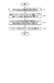
- FIG. 5 is a flowchart illustrating an example of an installation method of the magnetic resonance imaging apparatus 1a according to the first embodiment.
- Step S1 In step S1, the gantry 6 and the bed 13 are placed on the floor surface of the shield room R1. Note that the internal structure of the gantry 6 such as the magnetic field forming unit 7 is normally completed in the installation stage.
- Step S2 the noise radiation unit 14 such as the control unit 2, the sequence controller 3, the amplification unit 5, and the power supply unit 10 is placed on the floor surface of the shield room R1.
- Step S3 the floor board 1b is fixed to the wall surface of the shield room R1, the gantry 6 and the bed 13 through the board portion fixing jig 101 so that the gantry 6 and the bed 13 penetrate.
- the floor board 1b needs to be processed in advance in accordance with the shape formed by the wall surface of the shield room R1, the gantry 6 and the bed 13. Alternatively, the shape of the floor board 1b may be processed in this step.
- the magnetic-shielding processing and high-frequency noise shielding processing of the floor board 1b are usually preferably performed in advance, but may be performed in this step.
- Step S4 for example, some units such as the transceiver 4 that should be placed in the vicinity of the magnetic field forming unit due to the configuration are placed on the upper surface of the floor board 1b.
- the cooling fan 16 in the first modification when installing it outside the shield room R1 (for example, the machine room R2), it may be installed at any step or in advance.
- the partially detachable floor board 1b in the modified example 2 for example, the above-described various units placed on the floor surface of the shield room R1 in step S2, after step S3, for example, before or after step S4 or You may mount in the same step as step S4.
- the board part 100 in the floor board 1b is subjected to a magnetic-shielding process and a high-frequency noise shielding process.
- the floor board 1 b is located above the control unit 2, the sequence controller 3, the amplification unit 5, and the power supply unit 10 and below the magnetic field forming unit 7 in the gantry 6.
- the floor board 1b is located so that the noise radiation unit 14 and the magnetic field forming unit 7 are spatially separated.
- the RF receiving coil 9c Since the RF receiving coil 9c is not (or hardly) affected by high-frequency noise (frequency close to RF for obtaining NMR) radiated from the noise radiation unit 14, it is expected to generate a higher-definition MR image. Is done. In addition, it is possible to relax the design restrictions due to the magnetic-shield design for each unit. Similarly, design restrictions due to the high-frequency noise shielding design for each unit can be relaxed. By the relaxation of the above two design restrictions, the expandability of the magnetic resonance imaging apparatus 1a according to the first embodiment is improved. In addition, the design cost can be reduced by relaxing the above two design constraints. Further, for example, wireless communication can be realized between the various units placed in the second space without affecting the generated image.
- a frequency other than the RF band for example, infrared communication
- wireless communication between the unit placed in the first space and the unit placed in the second space can be realized.
- tandem mounting which is not preferable from the viewpoint of equipment fatigue or the like
- a vent is provided in a part of the wall between the shield room R1 and the outside of the shield room R1.
- a cooling fan 16 is installed in the vicinity of the vent on the outside of the shield room R1.
- the board unit 100 in the floor board 1b includes a detachable part 100a. That is, a user such as a doctor can remove the detachable part 100 a from the board unit 100 or attach it to the board unit 100 again. As a result, it is necessary to remove the gantry cover in the past, and it is possible to implement inspection, maintenance (maintenance) or replacement of various units that have been difficult to work by removing the detachable part 100a, thereby improving workability. There is expected. In addition to workability related to inspection, maintenance, or replacement of various units, it is possible to realize a magnetic resonance imaging apparatus 1a that is more expandable than before, such as introduction of a new unit. Furthermore, a new unit can be arranged without losing the design of the gantry cover or the like during the expansion.
- FIG. 6A is a bird's eye view showing the magnetic resonance imaging apparatus 1a according to the first embodiment, the shield room R1 in which the magnetic resonance imaging apparatus is installed, and the like.
- FIG. 6B is a plan view showing an example of an installation form of the magnetic resonance imaging apparatus 1a according to the second embodiment.
- description of the location which overlaps with the magnetic resonance imaging apparatus 1a which concerns on 1st Embodiment is abbreviate
- the gantry 6 and the bed 13 are placed on the floor board 1b in the magnetic resonance imaging apparatus 1a according to the second embodiment.
- the gantry 6 and the bed 13 are large in mass.
- the magnetic field forming unit 7 in the gantry 6 has a large mass because it includes a static magnetic field magnet and the like.
- the base 15 that can withstand the weight based on the mass of the gantry 6 is positioned vertically below the gantry 6 (and the bed 13) and supports the floor board 1b so that the floor board 1b can withstand the weight based on the mass. It is possible to be placed on the floor surface of the shield room R1.
- the electromagnetic shielding of the first space and the second space is magnetic resonance in the first embodiment. It is achieved with higher accuracy than the imaging apparatus 1a.
- the modification 1 (use of the cooling fan 16) or the modification 2 (partially removable) described in the magnetic resonance imaging apparatus 1a according to the first embodiment is used. You may implement.
- FIG. 7 is a flowchart showing an example of an installation method of the magnetic resonance imaging apparatus 1a according to the second embodiment.
- Step S11 a base 15 that can withstand the weight based on the mass of the gantry 6 is provided on the floor surface of the shield room R1.
- Step S12 the noise radiation unit 14 such as the control unit 2, the sequence controller 3, the amplification unit 5, and the power supply unit 10 is placed on the floor surface of the shield room R1.
- step S13 the floor board 1b is fixed to the wall surface of the shield room R1 through the board portion fixing jig 101.
- the floor board 1b needs to be processed in advance according to the shape formed by the wall surface of the shield room R1. Alternatively, the shape of the floor board 1b may be processed in this step.
- the magnetic-shielding processing and high-frequency noise shielding processing of the floor board 1b are usually preferably performed in advance, but may be performed in this step.
- Step S14 In step S ⁇ b> 14, the mass 6 and the bed 13 having a large mass are placed on the upper surface of the floor board 1 b so as to be positioned vertically above the base 15.
- Step S15 for example, a part of the unit such as the transceiver 4 that should be placed in the vicinity of the magnetic field forming unit is placed on the upper surface of the floor board 1b.
- the cooling fan 16 in the modification 1 when installing in the shield room R1 exterior, it may install in any step or may install previously.
- the partially removable floor board 1b in the modified example 2 the above-described various units placed on the floor surface of the shield room R1 in step S12, for example, after step S13, for example, before and after step S15 Or you may mount in the same step as step S15.
- the base 15 that can withstand the weight based on the mass of the gantry 6 is configured so that the floor board 1b can withstand the weight based on the mass. 13) is placed on the floor surface of the shield room R1 so as to be able to support the floor board 1b. Accordingly, the shape processing of the floor board 1b is facilitated as compared with the magnetic resonance imaging apparatus 1a according to the first embodiment.
- the floor board 1b is arranged with a certain height compared to the floor surface of the shield room R1. For this reason, when viewed from a doctor or subject moving on the board, the mounting space of the subject on the gantry 6 and the height of the top plate 13a are higher than the height in the conventional magnetic resonance imaging apparatus, It will be low.
- the magnetic resonance imaging apparatus 1a according to the second embodiment while maintaining the mounting space of the subject and the height of the top plate 13a on the gantry 6 of the conventional magnetic resonance imaging apparatus, the above-mentioned first Effects similar to those of the magnetic resonance imaging apparatus 1a according to the embodiment can be obtained.
- the electromagnetic shielding of the first space and the second space is performed in the magnetic resonance imaging apparatus in the first embodiment. It is achieved with higher accuracy than 1a. As a result, it is possible to prevent equipment fatigue on various units placed in the second space and to generate a magnetic resonance imaging image with less noise.
- the present invention is not limited to the above-described embodiment as it is, and can be embodied by modifying constituent elements without departing from the scope of the invention in the implementation stage.
- Various inventions can be formed by appropriately combining a plurality of constituent elements disclosed in the embodiment. For example, some components may be deleted from all the components shown in the embodiment. Furthermore, constituent elements over different embodiments may be appropriately combined.
Landscapes
- Physics & Mathematics (AREA)
- Health & Medical Sciences (AREA)
- Life Sciences & Earth Sciences (AREA)
- Condensed Matter Physics & Semiconductors (AREA)
- General Physics & Mathematics (AREA)
- Engineering & Computer Science (AREA)
- Animal Behavior & Ethology (AREA)
- Molecular Biology (AREA)
- Biophysics (AREA)
- Pathology (AREA)
- Biomedical Technology (AREA)
- Heart & Thoracic Surgery (AREA)
- Medical Informatics (AREA)
- Nuclear Medicine, Radiotherapy & Molecular Imaging (AREA)
- Surgery (AREA)
- Veterinary Medicine (AREA)
- General Health & Medical Sciences (AREA)
- Public Health (AREA)
- High Energy & Nuclear Physics (AREA)
- Radiology & Medical Imaging (AREA)
- Signal Processing (AREA)
- Magnetic Resonance Imaging Apparatus (AREA)
Abstract
実施形態に係る磁気共鳴イメージング装置は、シールドルーム内に設置され、静磁場磁石、傾斜磁場コイル、及びRFコイルを有する架台と、被検者が載置される寝台と、前記磁気共鳴イメージング装置の制御に係る少なくとも一つのユニットとを備える。前記少なくとも一つのユニットは、保守点検のための開口部が、上面に設けられている。
Description
本発明の実施形態は、磁気共鳴イメージング装置及び磁気共鳴イメージング装置の設置方法に関する。
磁気共鳴イメージング(MRI:Magnetic Resonance Imaging)装置は、医用画像診断の分野で広く普及している。MRIとは、磁気共鳴現象に基づく撮像法であって、静磁場が形成された空間に置かれた被検体の有する原子核(1H等)スピンを、ラーモア周波数のRF(RF:radio frequency)信号で磁気的に励起し、当該励起に伴って発生する核磁気共鳴(NMR:nuclear magnetic resonance)信号から、画像を再構成する撮像法である。
通常、ホストコンピュータや電源類等、各種ユニットは、機械室と呼ばれる撮影室とは異なる部屋に設置される。これは、当該各種ユニットからのノイズ放射及び撮影室に形成された静磁場の当該各種ユニットへの影響、の防止に由来する。
一方で近年は、省スペース設置を実現するために、当該各種ユニットを機械室ではなく撮影室に設置する傾向が見られる。
しかしながら係る場合、当該各種ユニットの、磁場耐性化とノイズ放射抑制とが必要となり、コスト増等の問題が想定される。
目的は、従来に比して省スペース設置を実現できる磁気共鳴イメージング装置及び磁気共鳴イメージング装置の設置方法を提供することにある。
実施形態に係る磁気共鳴イメージング装置は、シールドルーム内に設置され、静磁場磁石、傾斜磁場コイル、及びRFコイルを有する架台と、被検者が載置される寝台と、前記磁気共鳴イメージング装置の制御に係る少なくとも一つのユニットとを備える。前記少なくとも一つのユニットは、保守点検のための開口部が、上面に設けられている。
以下、図面を参照しながら実施形態を説明する。なお、以下の説明において、略同一の構成を有する構成要素については、同一符号を付し、重複説明は必要な場合にのみ行う。
(第1の実施形態)
図1Aは、第1の実施形態に係る磁気共鳴イメージング装置1a、及び当該磁気共鳴イメージング装置が設置されるシールドルームR1等を示した鳥瞰図である。図1Bは、第1の実施形態に係る磁気共鳴イメージング装置1a及びフロアボード1bを具備する磁気共鳴イメージングシステム1の一例を示すブロック図である。
図1Aは、第1の実施形態に係る磁気共鳴イメージング装置1a、及び当該磁気共鳴イメージング装置が設置されるシールドルームR1等を示した鳥瞰図である。図1Bは、第1の実施形態に係る磁気共鳴イメージング装置1a及びフロアボード1bを具備する磁気共鳴イメージングシステム1の一例を示すブロック図である。
図1Aに示す様に、シールドルームR1の床面から所定の高さにおいて、フロアボード1bが敷設されている。フロアボード1b、シールドルームR1の天井、シールドルームの側面(壁)よって囲まれた空間(すなわち、フロアボード1bよりも上方の空間)は撮影室r1を形成する。一方、フロアボード1b、シールドルームR1の床面、シールドルームの壁よって囲まれた空間(すなわち、フロアボード1bよりも下方の空間)は収納室r2を形成する。フロアボード1bは、防磁加工と高周波ノイズ遮蔽(又は遮断)加工とが施されている。従って、撮影室r1と収納室r2とは、電磁的に遮蔽される。
磁気共鳴イメージング装置1aは、制御ユニット2、シーケンスコントローラ3、トランシーバ4、増幅ユニット5、架台6、電源ユニット10,表示部11、入力部12、及び寝台13を有する。まず、これら各ユニットの構成、機能について説明する。
制御ユニット2は、磁気共鳴イメージング装置1aに係る動作全般の制御を担う。制御ユニット2は、例えば、メモリ、ハードディスク、CPU等を有するホストコンピュータと、トランシーバより送信されるデータ(NMR信号に基づく電気信号)を収集するデータ収集部と、収集されたデータからMR画像を再構成する画像再構成部と、寝台13を調整可能に制御する寝台制御部とを有する。但し、この限りではない。なお、詳細な動作については、他の部分の説明と関連して改めて説明する。
シーケンスコントローラ3は、増幅ユニット5における傾斜ドライバ5aとトランシーバ4とに接続されており、傾斜磁場を発生させるための電気信号の送信と、RF(正確には、RFの磁場成分)パルスを発生させるための電気信号の送受信(トランシーバ4を介する)とに係るシーケンスを制御する。すなわち、シーケンスコントローラ3は決められたタイミングで、トリガを接続先に送信する。
トランシーバ4は、被検体有する原子核を励起するRFパルスを発生させるための電気信号を、トランスミッタ5bを介して、送信する。また、トランシーバ4は、RFパルスによって励起された原子核が元に戻る際に発するNMR信号に基づく電気信号を、プリアンプ5cを介して、受信する。更にトランシーバ4は、当該NMR信号に基づく電気信号を制御ユニット2に送信する。
増幅ユニット5は、傾斜ドライバ5a(傾斜磁場を発生させるための電気信号を増幅、送信するアンプ)、トランスミッタ5b(RFパルスを発生させるための電気信号を増幅、送信するアンプ)、プリアンプ5c(NMR信号に基づく電気信号を増幅、送信するアンプ)の総称である。傾斜ドライバ5aは、傾斜磁場コイル9aが傾斜磁場を形成するように、シーケンスコントローラからのトリガに同期して、電気信号を傾斜磁場コイル9aに送信する。トランスミッタ5bは、トランシーバ4のトリガに同期して、電気信号をRF送信コイル9bに送信する。プリアンプ5cは、被検体よりRF受信コイル9cを介して得られたNMR信号に基づく電気信号(微弱)を増幅して、当該電気信号をトランシーバ4に送信する。
架台6は、静磁場磁石8と傾斜磁場コイル9aとRF送信コイル9bとRF受信コイル9cとを有する。また、静磁場磁石8と傾斜磁場コイル9aとRF送信コイル9bとRF受信コイル9cとを総称して、磁場形成ユニット7と呼ぶものとする。
静磁場磁石8は、本実施形態では一般的な超電導磁石を想定するものとする。静磁場磁石8は、被検体の置かれた空間に静磁場を形成する。なお、静磁場磁石8は、常電導磁石でもよいし、永久磁石でもよい。
傾斜磁場コイル9aは、傾斜ドライバ5aからの電気信号の入力に応答して、傾斜磁場を形成する。なお、傾斜磁場コイル9aは、X、Y、Zの3軸に対応する三のコイルを有する。ただし図1では、図の煩雑化を防ぐため、傾斜磁場コイル9aという一の定義付けを行っている。当該傾斜磁場により、被検体内の原子核は、各原子核の位置毎に、異なるラーモア周波数を有することになる。すなわち、当該ラーモア周波数の違いにより、NMR信号から、断面の位置情報を区別することが可能となる。
RF送信コイル9bは、トランスミッタ5bからの電気信号の入力に応答して、RFパルスを被検体に送信する。RFパルスは、固有のラーモア周波数に対応する、被検体の原子核を励起させる。
RF受信コイル9cは、被検体有する原子核が励起状態から元に戻る際に発生されるNMR信号を受信し、当該NMR信号に基づく電子信号(微弱)をプリアンプ5cに送信する。
なお、本実施形態では、RF送信コイル9bとRF受信コイル9cとを別々のコイルとしているが、変形例として同一のコイルとして実施してもよい。
なお、本実施形態では、RF送信コイル9bとRF受信コイル9cとを別々のコイルとしているが、変形例として同一のコイルとして実施してもよい。
電源ユニット10は複数の電源、例えば五の電源を有し、増幅ユニットにおける各増幅器(三のコイルから成る傾斜磁場コイル9a、RF送信コイル9b、及びRF受信コイル9cにそれぞれ対応)に電圧を印加する。
表示部11は、制御ユニット2と接続され、例えば、撮影されたMRI画像を表示する。
入力部12は、制御ユニット2と接続され、例えば、スイッチボタン、マウス、キーボード等を介して、医師等の操作者の指示入力を受け付ける。当該指示入力は、制御ユニット2におけるホストコンピュータに転送される。ホストコンピュータは当該指示入力に応じて、所定の制御や演算を実行する。例えば、操作者が表示部11にて表示されているMRI画像における所定の関心領域(Region of Interest:ROI)だけに注目し、当該箇所を拡大表示したい場合を想定する。入力部12は、操作者によるROIの拡大に関する指示入力を受け付ける。当該指示入力は、ホストコンピュータに転送される。ホストコンピュータは、MRI画像の拡大処理を実行する。表示部11は、拡大処理の施されたMRI画像を表示する。
寝台13は、シールドルームR1の床面に設置され、天板13aの長手方向の位置を調整可能な不図示の調整機構を有する。制御ユニット2における寝台制御部は、当該調整機構を介して、天板13aを長手方向に移動させ、当該天板13aに載置された被検体を、架台6の内側に位置する被検体配置空間に配置する。
なお、図1Aに示した磁気共鳴イメージング装置1aの寝台13は、天板13aの高さ調整のための機構を有していない。これは、以下の理由による。すなわち、図1Aに示した撮影室r1の床面すなわちフロアボード1bは、シールドルームR1の床面から所定の高さに設置されている。寝台13の天板13aは、上下移動せずとも、架台6のボアの高さに位置しており且つフロアボード1b上の被検者が簡単に上り下りできる高さにある。このため、寝台13に天板13aの上下移動機構を設ける必要性は乏しい。
一般に、天板13aの上下移動は、子供に恐怖心を与える場合がある。また、高齢被検者にとっては、天板13aへの上り下りが体力的に困難である場合がある。図1Aに示した磁気共鳴イメージング装置1aによれば、被検者の天板13aへの上り下りや天板13aのボアへの誘導の際に、天板13aを上下移動させる必要がない。従って、被検者に体力的負担や心理的負担を与えることなく、安全に撮影を行うことができる。また、天板13aを上下移動させる必要がないため、その分の電力を節約するとができる。
なお、図1Aに示した例に拘泥されず、図1Cに示す様に、必要に応じて天板13aの高さ調整機構を有する寝台13を、シールドルームR1の床面に設置するようにしてもよい。
フロアボード1bは、撮影室r1の床を形成し、防磁加工と高周波ノイズ遮蔽(又は遮断)加工とが施されたボード部100(例えば、樹脂製等の非金属板)とボード部固定治具101(固定手段)とを有する。
ボード部固定治具101は、ボード部100を磁気共鳴イメージング装置1aに固定するための治具である。当該治具は、例えば凹凸部位やねじ穴等を有する。本実施形態に係る磁気共鳴イメージング装置1aとフロアボード1bとを組み合わせることで、磁気共鳴イメージングシステム1が実装される。
なお、強度確保の観点から、ボード部固定治具101に加えて、支柱や梁を用いてボード部100を支えるようにしてもよい。また、ボード部100は一体構造である必要はなく、複数のパネルを組み立てることによって実現するようにしてもよい。
次に、磁気共鳴イメージング装置1aが撮影室r1、収納室r2においてどのように設置されるかについて説明する。
図2は、第1の実施形態に係る磁気共鳴イメージング装置1aの設置形態の一例を示した平面図である。
図2に示した例では、架台6、寝台13、制御ユニット2、シーケンスコントローラ3、増幅ユニット5、及び電源ユニット10が、シールドルームR1の床面(すなわち、収納室r2内)に載置されている。制御ユニット2、シーケンスコントローラ3、増幅ユニット5、及び電源ユニット10は、RFの周波数帯域と干渉する高周波ノイズを発生ノイズするおそれがあるため、ここではノイズ放射ユニット14と呼ぶものとする。フロアボード1bにおけるボード部100は、磁気共鳴イメージング装置1a(例えば、図2においては、架台6及び寝台13)及びシールドルームR1の壁面と、ボード部固定治具101を介して、固定されている。一方、トランシーバ4は、フロアボード1bの上面(すなわち、撮影室r1内)に載置されている。
一方、架台6及び寝台13は、シールドルームR1の床面に設置され、フロアボード1bを貫通して、収納室r2及び撮影室r1の両方にまたがって位置している。従って、フロアボード1bは当該貫通する架台6及び寝台13と、シールドルームR1の壁面が成す形状(シールドルームR1の水平断面の形状)とに合わせて、予め又は設置中に加工される。
フロアボード1bにおけるボード部100は、上述の通り、防磁加工と高周波ノイズ遮蔽加工とを施されている。すなわち、ボード部100は、防磁層と防高周波層(防RF層)とを有する。磁場形成ユニット7は、磁気共鳴イメージングを行うための磁場(静磁場磁石8による静磁場及び傾斜磁場コイル9aによる傾斜磁場)を発生させる。ボード部100有する防磁層は、当該磁場を遮蔽することで、磁場空間を撮影室r1に実現するとともに、収納室r2には実現させない。
一方、ノイズ放射ユニット14は、その動作時において、して磁気共鳴イメージングに使用するRFと周波数の近い高周波ノイズ(RFノイズ)を放射する場合がある。これは、ノイズ放射ユニット14における各種ユニットが、ケーブルによって接続される場合、或いは無線通信する場合のいずれであっても起こりうる。ボード部100有する防高周波層は、当該高周波ノイズを遮蔽することで、当該高周波ノイズの第1の空間への伝搬を防止する。
また、フロアボード1bは、撮影室r1の床面としての機能も果たす。従って、医師や被検者は、フロアボード1b上を自由に行き来することができる。
なお、図1A等に示した第1の実施形態に係る磁気共鳴イメージング装置1aでは、架台6がシールドルームR1床面に設置されている。このため、例えば架台6とフロアボード1bとの間から、収納室r2への静磁場の漏れや、撮影室r1へのノイズ放射ユニット14による高周波ノイズの漏れが存在する。しかしながら、当該漏れは、フロアボード1bを設置しない場合と比して、微弱なものである。また、当該微弱な漏れを防止するために、架台6の防磁性、防高周波性を強化してもよい。
また、図1A、図1Cに示した例では、シールドルームR1に隣接する機械室R2が設けられている。機械室R2には、必要に応じて、磁気共鳴イメージング装置1aが有する制御ユニット2、シーケンスコントローラ3、増幅ユニット5、電源ユニット10、その他のユニットのうち、所望の装置或いは機械を設置することができる(図1A,図1Cの例では、形式的にユニットU1、U2と記載している)。しかしながら、機械室R2の設置は必須ではない。例えば、機械室R2に設けられるユニットU1、U2を収納室r2に設置することで機械室R2を縮小或いは省略でき、さらなる省スペース化を実現することも可能である。
(配線)
本実施形態に係る磁気共鳴イメージング装置1aでは、ノイズ放射ユニット14は収納室r2に設置され、磁場形成ユニット7や天板13a等は、撮影室r1に設置される。また、必要に応じて、磁気共鳴イメージング装置1aの所定のユニットU1等が機械室R2に設置される場合もある。この様にそれぞれ異なる空間に配置されたユニット間のケーブル配線は、シールドルームR1や撮影室r1の電磁的遮蔽性を維持した状態で実現する必要がある。
本実施形態に係る磁気共鳴イメージング装置1aでは、ノイズ放射ユニット14は収納室r2に設置され、磁場形成ユニット7や天板13a等は、撮影室r1に設置される。また、必要に応じて、磁気共鳴イメージング装置1aの所定のユニットU1等が機械室R2に設置される場合もある。この様にそれぞれ異なる空間に配置されたユニット間のケーブル配線は、シールドルームR1や撮影室r1の電磁的遮蔽性を維持した状態で実現する必要がある。
そこで、本実施形態に係る磁気共鳴イメージング装置1aでは、収納室r2に設置されるノイズ放射ユニット14等の所定の装置は、シールドルームR1の床とフロアボード1bとの二重床構造に設けられたフィルタパネル(電磁的遮蔽性を有する配線パネルであり、例えばフロアボード1b或いは収納室r2に設置される。図1A、図1Cにおいては図示せず。)を介して、架台6から引き出され当該架台6の下部に集約されたケーブルに接続される。また、収納室r2に設置されるノイズ放射ユニット14等の所定の装置から引き出されるケーブル、或いは架台6から引き出され当該架台6の下部に集約されたケーブルは、収納室r2と機械室R2との間の壁面に設けられたフィルタパネル200を介して、機械室R2に設置された所定のユニットU1等と接続される。
この様な構成によれば、それぞれ異なる空間に配置されたユニット間を接続するケーブルを、電磁的遮蔽性を維持した状態で一か所に集約することができる。その結果、設置、保守、点検等を行う場合において、作業負担を軽減させることができる。
(収納室r2に配置されるユニットの保守・点検のための構成)
収納室r2に配置される制御ユニット2等のノイズ放射ユニット14についてメンテナンス或いは修理する場合には、ボード部100の一部を外し、撮影室r1側から各ユニットの配線や内部を確認することが想定される。係る事情から、本実施形態に係る磁気共鳴イメージング装置1aが具備し収納室r2に設置されるノイズ放射ユニット14等は、その上面に配置された各種スイッチ、接続端子、表示画面、パイロットランプ、装置内部にアクセスするため(保守点検するため)の開口部等を有している。係る構成によれは、作業者は、撮影室r1側から各ユニットの配線や内部を容易に点検することができる。その結果、保守・点検時の作業負担を大幅に低減させることができる。
収納室r2に配置される制御ユニット2等のノイズ放射ユニット14についてメンテナンス或いは修理する場合には、ボード部100の一部を外し、撮影室r1側から各ユニットの配線や内部を確認することが想定される。係る事情から、本実施形態に係る磁気共鳴イメージング装置1aが具備し収納室r2に設置されるノイズ放射ユニット14等は、その上面に配置された各種スイッチ、接続端子、表示画面、パイロットランプ、装置内部にアクセスするため(保守点検するため)の開口部等を有している。係る構成によれは、作業者は、撮影室r1側から各ユニットの配線や内部を容易に点検することができる。その結果、保守・点検時の作業負担を大幅に低減させることができる。
(変形例1)
図3は、第1の実施形態に係る磁気共鳴イメージング装置1aにおいて、冷却ファン16(冷却機構)を含む変形例を示す平面図である。当該変形例においては、収納室r2と収納室r2外部(例えば機械室R2)との間の壁の一部に通気口が設けられている。さらに、冷却ファン16が、収納室r2外部側の通気口近傍に設置されている。冷却ファン16は、第2の空間内に対流を発生させることで、例えば、発熱を伴う電源ユニット10を冷却する。冷却ファン16は、モータを用いているため、磁場環境では動作しない。当該変形例では、上記理由のため、念のため冷却ファン16は、収納室r2外部に設置されている。しかしながら、フロアボード1bにおけるボード部100の防磁性能を高めれば、冷却ファン16は、ノイズ放射ユニット14と同様に、収納室r2内に設置されてもよい。
図3は、第1の実施形態に係る磁気共鳴イメージング装置1aにおいて、冷却ファン16(冷却機構)を含む変形例を示す平面図である。当該変形例においては、収納室r2と収納室r2外部(例えば機械室R2)との間の壁の一部に通気口が設けられている。さらに、冷却ファン16が、収納室r2外部側の通気口近傍に設置されている。冷却ファン16は、第2の空間内に対流を発生させることで、例えば、発熱を伴う電源ユニット10を冷却する。冷却ファン16は、モータを用いているため、磁場環境では動作しない。当該変形例では、上記理由のため、念のため冷却ファン16は、収納室r2外部に設置されている。しかしながら、フロアボード1bにおけるボード部100の防磁性能を高めれば、冷却ファン16は、ノイズ放射ユニット14と同様に、収納室r2内に設置されてもよい。
(変形例2)
図4Aは、第1の実施形態に係る磁気共鳴イメージング装置1aにおいて、部分脱着可能なフロアボード1bを含む変形例を示す平面図である。当該変形例において、フロアボード1bにおけるボード部100は、脱着パーツ100aを含む。図4Aでは、一の脱着パーツ100aが示されているが、実際は複数の脱着パーツ100aであってもよい。また、ボード部100が組み立てられた複数のパネルによって構成される場合には、一つ或いは数枚の取り外し可能なパネルによって、脱着パーツ100aを実現するようにしてもよい。
図4Aは、第1の実施形態に係る磁気共鳴イメージング装置1aにおいて、部分脱着可能なフロアボード1bを含む変形例を示す平面図である。当該変形例において、フロアボード1bにおけるボード部100は、脱着パーツ100aを含む。図4Aでは、一の脱着パーツ100aが示されているが、実際は複数の脱着パーツ100aであってもよい。また、ボード部100が組み立てられた複数のパネルによって構成される場合には、一つ或いは数枚の取り外し可能なパネルによって、脱着パーツ100aを実現するようにしてもよい。
例えば、ノイズ放射ユニット14の点検や整備等の際、サービスマン或いは医師等の使用者は、制御ユニット2やシーケンスコントローラ3等の点検、整備を目的として、脱着パーツ100aをボード部100から取り外す。サービスマン等は、当該点検、整備の終了後、脱着パーツ100aをボード部100に再び取り付ける。この様にして、脱着パーツ100aを取り外すことで、収納室r2に設置されたユニットに迅速且つ簡単にアクセスすることができる。
(変形例3)
図1A,図1Cにおいては、収納室r2に配置される複数のユニットは、ケーブルによって相互に接続され、通信等を行う場合を例示した。これに拘泥されず、収納室r2に配置される複数のユニットは、図4Bに示す様に、互いに無線通信を行うようにしてもよい。同様に、収納室r2に配置される複数のユニットと、機械室に設置された所定のユニットとが、互いに無線通信を行うようにしてもよい。さらに、設置環境に応じて、無線通信と優先通信とを併用するようにしてもよい。なお、図4Bに示した様に、機械室に設置された所定のユニット側に設けられる無線通信用のアンテナは、フィルタパネル200を介して収納室r2内に設けられることになる。
図1A,図1Cにおいては、収納室r2に配置される複数のユニットは、ケーブルによって相互に接続され、通信等を行う場合を例示した。これに拘泥されず、収納室r2に配置される複数のユニットは、図4Bに示す様に、互いに無線通信を行うようにしてもよい。同様に、収納室r2に配置される複数のユニットと、機械室に設置された所定のユニットとが、互いに無線通信を行うようにしてもよい。さらに、設置環境に応じて、無線通信と優先通信とを併用するようにしてもよい。なお、図4Bに示した様に、機械室に設置された所定のユニット側に設けられる無線通信用のアンテナは、フィルタパネル200を介して収納室r2内に設けられることになる。
(設置方法)
図5は、第1の実施形態に係る磁気共鳴イメージング装置1aの設置方法の一例を表すフローチャートである。
図5は、第1の実施形態に係る磁気共鳴イメージング装置1aの設置方法の一例を表すフローチャートである。
(ステップS1)
ステップS1において、架台6及び寝台13を、シールドルームR1の床面に載置する。なお、磁場形成ユニット7等、架台6の内部構造については、通常、設置段階において完成しているものとする。
ステップS1において、架台6及び寝台13を、シールドルームR1の床面に載置する。なお、磁場形成ユニット7等、架台6の内部構造については、通常、設置段階において完成しているものとする。
(ステップS2)
ステップS2において、制御ユニット2、シーケンスコントローラ3、増幅ユニット5、電源ユニット10等のノイズ放射ユニット14を、シールドルームR1の床面に載置する。
ステップS2において、制御ユニット2、シーケンスコントローラ3、増幅ユニット5、電源ユニット10等のノイズ放射ユニット14を、シールドルームR1の床面に載置する。
(ステップS3)
ステップS3において、フロアボード1bを、架台6及び寝台13が貫通するように、ボード部固定治具101を介して、シールドルームR1の壁面、架台6及び寝台13に固定する。なお、フロアボード1bはシールドルームR1の壁面が成す形状、架台6及び寝台13に合わせて、予め形状を加工しておく必要がある。或いは、本ステップにおいてフロアボード1bの形状を加工してもよい。
ステップS3において、フロアボード1bを、架台6及び寝台13が貫通するように、ボード部固定治具101を介して、シールドルームR1の壁面、架台6及び寝台13に固定する。なお、フロアボード1bはシールドルームR1の壁面が成す形状、架台6及び寝台13に合わせて、予め形状を加工しておく必要がある。或いは、本ステップにおいてフロアボード1bの形状を加工してもよい。
フロアボード1bの防磁加工及び高周波ノイズ遮蔽加工については、通常は予め行うものが好ましいが、本ステップにおいて、当該加工を施してもよい。
(ステップS4)
ステップS4において、例えば、構成上、磁場形成ユニットの近傍に載置すべきであるトランシーバ4等の一部のユニットを、フロアボード1bの上面に載置する。
ステップS4において、例えば、構成上、磁場形成ユニットの近傍に載置すべきであるトランシーバ4等の一部のユニットを、フロアボード1bの上面に載置する。
(変形例を用いる場合)
変形例1における冷却ファン16を使用するにあたり、シールドルームR1外部(例えば機械室R2)に設置する場合は、どのステップで設置しても、或いは予め設置しておいてもかまわない。変形例2における部分脱着可能なフロアボード1bを使用するにあたり、例えばステップS2でシールドルームR1の床面に載置される上述の各種ユニットを、ステップS3よりも後、例えば、ステップS4の前後又はステップS4と同じステップに載置してもよい。
変形例1における冷却ファン16を使用するにあたり、シールドルームR1外部(例えば機械室R2)に設置する場合は、どのステップで設置しても、或いは予め設置しておいてもかまわない。変形例2における部分脱着可能なフロアボード1bを使用するにあたり、例えばステップS2でシールドルームR1の床面に載置される上述の各種ユニットを、ステップS3よりも後、例えば、ステップS4の前後又はステップS4と同じステップに載置してもよい。
また、当該設置方法のステップには図示していないが、有線通信、電源等の配線は、各ステップにおいて適宜行えばよい。
(効果)
第1の実施形態に係る磁気共鳴イメージング装置1aによれば、以下の効果を得ることができる。
第1の実施形態に係る磁気共鳴イメージング装置1aによれば、以下の効果を得ることができる。
フロアボード1bにおけるボード部100は、防磁加工と高周波ノイズ遮蔽加工とを施されている。フロアボード1bは、制御ユニット2、シーケンスコントローラ3、増幅ユニット5,及び電源ユニット10よりも上方に、かつ架台6における磁場形成ユニット7よりも下方に位置している。フロアボード1bは、ノイズ放射ユニット14と磁場形成ユニット7とを空間的に隔てるように、位置している。これより、制御ユニット2、シーケンスコントローラ3、増幅ユニット5,及び電源ユニット10等、各種ユニットへの磁場の影響による誤動作や機器疲労を防止することができる。RF受信コイル9cは、ノイズ放射ユニット14から放射される高周波ノイズ(NMRを得るためのRFと周波数が近い)の影響を受けない(又は受けにくい)ので、より高精細なMR画像の生成が期待される。また、各種ユニット毎の、防磁設計による設計上の制約を緩和することができる。同様に、各種ユニット毎の、高周波ノイズ遮蔽設計による設計上の制約を緩和することができる。上記二の設計上の制約緩和により、第1の実施形態に係る磁気共鳴イメージング装置1aの拡張性が向上する。また、上記二の設計上の制約緩和により、設計にかかるコストを削減できる。更に、第2の空間に載置された各種ユニット間で、生成画像に影響することなく、例えば無線通信を実現することができる。また、RFバンド以外の周波数(例えば赤外線通信等)を用いれば、第1の空間に載置されたユニット及び第2の空間に載置されたユニット間での無線通信も実現可能である。そして、撮影室内のスペース確保のために、各種ユニットに対して往々にして行われている縦列載置(機器疲労等の観点で好ましくない)を行うことなく、撮影室内のスペースを確保することができる。
変形例1において、シールドルームR1とシールドルームR1外部との間の壁の一部に通気口が設けられている。
そして、冷却ファン16が、シールドルームR1外部側の通気口近傍に設置されている。これより、各種ユニットをシールドルームR1に設置する際に必要であった、大型のヒートシンク、水冷装置、或いは複雑なダクト等を必要とせず、スペースの節約を実現できる。
そして、冷却ファン16が、シールドルームR1外部側の通気口近傍に設置されている。これより、各種ユニットをシールドルームR1に設置する際に必要であった、大型のヒートシンク、水冷装置、或いは複雑なダクト等を必要とせず、スペースの節約を実現できる。
変形例2において、フロアボード1bにおけるボード部100は、脱着パーツ100aを含む。すなわち、医師等の使用者は、脱着パーツ100aをボード部100から取り外すことや、ボード部100に再び取り付けることができる。これより、従来は架台カバーの取り外しが必要であり、作業性に難のあった各種ユニットの点検、整備(メンテナンス)又は交換を、脱着パーツ100aを取り外すことで実現できるものとなり、作業性の向上が期待される。また、各種ユニットの点検、整備又は交換に関する作業性だけでなく、新たなユニットの導入等、従来に比してより拡張性の高い磁気共鳴イメージング装置1aを実現することができる。更に、当該拡張時に際しても、架台カバー等のデザイン性を失うことなく、新たなユニットを配置できる。
(第2の実施形態)
図6Aは、第1の実施形態に係る磁気共鳴イメージング装置1a、及び当該磁気共鳴イメージング装置が設置されるシールドルームR1等を示した鳥瞰図である。図6Bは、第2の実施形態に係る磁気共鳴イメージング装置1aの設置形態の一例を示した平面図である。なお、第1の実施形態に係る磁気共鳴イメージング装置1aと比して重複する箇所の説明は、省略する。
図6Aは、第1の実施形態に係る磁気共鳴イメージング装置1a、及び当該磁気共鳴イメージング装置が設置されるシールドルームR1等を示した鳥瞰図である。図6Bは、第2の実施形態に係る磁気共鳴イメージング装置1aの設置形態の一例を示した平面図である。なお、第1の実施形態に係る磁気共鳴イメージング装置1aと比して重複する箇所の説明は、省略する。
第2の実施形態に係る磁気共鳴イメージング装置1aでは、第1の実施形態に係る磁気共鳴イメージング装置1aとは異なり、架台6及び寝台13がフロアボード1b上に載置されている。架台6及び寝台13は質量が大きい。特に架台6における磁場形成ユニット7は、静磁場磁石等を含むため、質量が大きい。フロアボード1bが当該質量に基づく重量に耐えられるように、架台6の質量に基づく重量に耐久可能な土台15は、架台6(及び寝台13)の鉛直下方向に位置し、フロアボード1bを支持可能に、シールドルームR1の床面に載置される。
また、架台6がフロアボード1b上にあることより、第2の実施形態における磁気共鳴イメージング装置1aでは、第1の空間及び第2の空間の電磁的遮蔽が、第1の実施形態における磁気共鳴イメージング装置1aに比してより高精度に達成されている。
第1の実施形態に係る磁気共鳴イメージング装置1aにおいて説明した変形例1(冷却ファン16の使用)又は変形例2(部分脱着可能な)を、第2の実施形態に係る磁気共鳴イメージング装置1aにおいて実施してもよい。
(設置方法)
図7は、第2の実施形態に係る磁気共鳴イメージング装置1aの設置方法の一例を表すフローチャートである。
図7は、第2の実施形態に係る磁気共鳴イメージング装置1aの設置方法の一例を表すフローチャートである。
(ステップS11)
ステップS11において、架台6の質量に基づく重量に耐久可能な土台15をシールドルームR1の床面上に設ける。
ステップS11において、架台6の質量に基づく重量に耐久可能な土台15をシールドルームR1の床面上に設ける。
(ステップS12)
ステップS12において、制御ユニット2、シーケンスコントローラ3、増幅ユニット5、電源ユニット10等のノイズ放射ユニット14を、シールドルームR1の床面に載置する。
ステップS12において、制御ユニット2、シーケンスコントローラ3、増幅ユニット5、電源ユニット10等のノイズ放射ユニット14を、シールドルームR1の床面に載置する。
(ステップS13)
ステップS13において、フロアボード1bを、ボード部固定治具101を介して、シールドルームR1の壁面に固定する。なお、フロアボード1bはシールドルームR1の壁面が成す形状に合わせて、予め形状を加工しておく必要がある。或いは、本ステップにおいてフロアボード1bの形状を加工してもよい。
ステップS13において、フロアボード1bを、ボード部固定治具101を介して、シールドルームR1の壁面に固定する。なお、フロアボード1bはシールドルームR1の壁面が成す形状に合わせて、予め形状を加工しておく必要がある。或いは、本ステップにおいてフロアボード1bの形状を加工してもよい。
フロアボード1bの防磁加工及び高周波ノイズ遮蔽加工については、通常は予め行うものが好ましいが、本ステップにおいて、当該加工を施してもよい。
(ステップS14)
ステップS14において、質量の大きな架台6及び寝台13を、土台15の鉛直上方向に位置するように、フロアボード1bの上面に載置する。
ステップS14において、質量の大きな架台6及び寝台13を、土台15の鉛直上方向に位置するように、フロアボード1bの上面に載置する。
(ステップS15)
ステップS15において、例えば、構成上、磁場形成ユニットの近傍に載置すべきであるトランシーバ4等の一部のユニットを、フロアボード1bの上面に載置する。
ステップS15において、例えば、構成上、磁場形成ユニットの近傍に載置すべきであるトランシーバ4等の一部のユニットを、フロアボード1bの上面に載置する。
(変形例を用いる場合)
変形例1における冷却ファン16を使用する場合は、シールドルームR1外部に設置する場合は、どのステップで設置しても、或いは予め設置しておいてもかまわない。変形例2における部分脱着可能なフロアボード1bを使用する場合は、例えばステップS12でシールドルームR1の床面に載置される上述の各種ユニットを、ステップS13よりも後、例えば、ステップS15の前後又はステップS15と同じステップに載置してもよい。
変形例1における冷却ファン16を使用する場合は、シールドルームR1外部に設置する場合は、どのステップで設置しても、或いは予め設置しておいてもかまわない。変形例2における部分脱着可能なフロアボード1bを使用する場合は、例えばステップS12でシールドルームR1の床面に載置される上述の各種ユニットを、ステップS13よりも後、例えば、ステップS15の前後又はステップS15と同じステップに載置してもよい。
また、当該設置方法のステップには図示していないが、有線通信、電源等の配線は、各ステップにおいて適宜行えばよい。
(効果)
第2の実施形態に係る磁気共鳴イメージング装置1aによれば、上述の第1の実施形態に係る磁気共鳴イメージング装置1aによる効果以外にも、以下の効果を得ることができる。
第2の実施形態に係る磁気共鳴イメージング装置1aによれば、上述の第1の実施形態に係る磁気共鳴イメージング装置1aによる効果以外にも、以下の効果を得ることができる。
第2の実施形態に係る磁気共鳴イメージング装置1aにおいて、フロアボード1bが、当該質量に基づく重量に耐えられるように、架台6の質量に基づく重量に耐久可能な土台15は、架台6(及び寝台13)の鉛直下方向に位置し、フロアボード1bを支持可能に、シールドルームR1の床面に載置される。従って、第1の実施形態に係る磁気共鳴イメージング装置1aに比して、フロアボード1bの形状加工が容易になる。
第1の実施形態に係る磁気共鳴イメージング装置1aでは、フロアボード1bが、シールドルームR1床面に比してある程度の高さを有して配置される。このため、ボード上を移動する医師や被検者から見て、架台6における被検体の載置空間や天板13aの高さは、従来の磁気共鳴イメージング装置における当該高さに比して、低いものとなる。一方、第2の実施形態に係る磁気共鳴イメージング装置1aでは、従来の磁気共鳴イメージング装置の架台6における被検体の載置空間や天板13aの高さを維持しつつも、上述の第1の実施形態に係る磁気共鳴イメージング装置1aと同様の効果を得ることができる。
架台6がフロアボード1b上にあることより、第2の実施形態における磁気共鳴イメージング装置1aでは、第1の空間及び第2の空間の電磁的遮蔽が、第1の実施形態における磁気共鳴イメージング装置1aに比してより高精度に達成されている。これにより、第2の空間へ載置する各種ユニットへの機器疲労の防止と、よりノイズの少ない磁気共鳴イメージング画像の生成を実現することができる。
なお、本発明は上記実施形態そのままに限定されるものではなく、実施段階ではその要旨を逸脱しない範囲で構成要素を変形して具体化できる。上記実施形態に開示されている複数の構成要素の適宜な組み合わせにより、種々の発明を形成できる。例えば、実施形態に示される全構成要素から幾つかの構成要素を削除してもよい。更に、異なる実施形態にわたる構成要素を適宜組み合わせてもよい。
1…磁気共鳴イメージングシステム、1a…磁気共鳴イメージング装置、1b…フロアボード、2…制御ユニット、3…シーケンスコントローラ、4…トランシーバ、5…増幅ユニット、5a…傾斜ドライバ、5b…トランスミッタ、5c…プリアンプ、6…架台、7…磁場形成ユニット、8…静磁場磁石、9…寝台、9a…傾斜磁場コイル、9b…RF送信コイル、9c…RF受信コイル、10…電源ユニット、11…表示部、12…入力部、13…寝台、13a…天板、14…ノイズ放射ユニット、15…土台、16…冷却ファン、100…ボード部、100a…脱着パーツ、101…ボード部固定治具、R1…シールドルーム、R2…機械室、r1…撮影室、r2…収納室
Claims (18)
- シールドルーム内に設置される磁気共鳴イメージング装置であって、
静磁場磁石、傾斜磁場コイル、及びRFコイルを有する架台と、
被検者が載置される寝台と、
前記磁気共鳴イメージング装置の制御に係る少なくとも一つのユニットと、を備え、
前記少なくとも一つのユニットは、保守点検のための開口部が上面に設けられている、
磁気共鳴イメージング装置。 - 前記少なくとも一つのユニットは、前記シールドルームの床面と、前記シールドルームの床面から所定の高さの位置に敷設されたボードとの間の空間に設置される、
請求項1に記載の磁気共鳴イメージング装置。 - 前記少なくとも一つのユニットは、前記RFコイルに供給されるRFパルスを増幅するRFアンプを有する、
請求項1に記載の磁気共鳴イメージング装置。 - 前記シールドルームの床面と前記ボードとの間の空間に、複数のユニットが設置され、
前記複数のユニットは互いに無線通信を行う、請求項2に記載の磁気共鳴イメージング装置。 - 前記複数のユニットは、前記RFコイルに供給されるRFパルスを増幅するRFアンプを有する、
請求項4に記載の磁気共鳴イメージング装置。 - 前記シールドルームの床面と前記ボードとの間の空間に、少なくとも一つの第1のユニットが設置され、
前記シールドルームの外の空間に少なくとも一つの第2のユニットが設置され、
前記少なくとも一つの第1のユニットと記少なくとも一つの第2のユニットとは、互いに無線通信を行う、請求項2に記載の磁気共鳴イメージング装置。 - 前記少なくとも一つの第1のユニットは、前記RFコイルに供給されるRFパルスを増幅するRFアンプを有する、
請求項6に記載の磁気共鳴イメージング装置。 - 前記寝台は、天板の上下移動機構を有さない、
請求項1に記載の磁気共鳴イメージング装置。 - シールドルーム内に磁気共鳴イメージング装置を設置する設置方法であって、
静磁場磁石、傾斜磁場コイル、及びRFコイルを有する架台、並びに寝台を前記シールドルームの床面に設置し、
前記シールドルームの床面から所定の高さの位置にボードを敷設して二重床構造を形成し、
前記シールドルームの床面と前記ボードとの間の空間に、前記磁気共鳴イメージング装置のユニットを設置する、設置方法。 - 前記ボードは電磁シールド機能を有する、請求項9に記載の設置方法。
- 前記シールドルームの床面と前記ボードとの間の空間に設置されるユニットは、前記RFコイルに供給されるRFパルスを増幅するRFアンプである、
請求項9に記載の設置方法。 - 前記シールドルームの床面と前記ボードとの間の空間に設置されるユニットは、前記二重床構造に設けられたフィルタパネルを介して、
前記架台の下部に集約されたケーブルに接続される、請求項9に記載の設置方法。 - 前記ボードの少なくとも一部は、脱着可能であることを特徴とする請求項9記載の設置方法。
- シールドルーム内に磁気共鳴イメージング装置を設置する設置方法であって、
静磁場磁石、傾斜磁場コイル、及びRFコイルを有する架台、並びに寝台を、前記シールドルームに設けられた土台の上に設置し、
前記シールドルームの床面から所定の高さの位置にボードを敷設して二重床構造を形成し、
前記シールドルームの床面と前記ボードとの間の空間に、前記磁気共鳴イメージング装置のユニットを設置する、設置方法。 - 前記ボードは、電磁シールド機能を有する、請求項14に記載の設置方法。
- 前記シールドルームの床面と前記ボードとの間の空間に設置されるユニットは、前記RFコイルに供給されるRFパルスを増幅するRFアンプである、
請求項14に記載の設置方法。 - 前記シールドルームの床面と前記ボードとの間の空間に設置されるユニットは、前記二重床構造に設けられたフィルタパネルを介して、
前記架台の下部に集約されたケーブルに接続される、請求項14に記載の設置方法。 - 前記ボードの少なくとも一部は、脱着可能であることを特徴とする請求項14記載の設置方法。
Priority Applications (1)
| Application Number | Priority Date | Filing Date | Title |
|---|---|---|---|
| US15/631,281 US10663539B2 (en) | 2014-12-24 | 2017-06-23 | Magnetic resonance imaging apparatus and method of installing magnetic resonance imaging apparatus |
Applications Claiming Priority (2)
| Application Number | Priority Date | Filing Date | Title |
|---|---|---|---|
| JP2014261034 | 2014-12-24 | ||
| JP2014-261034 | 2014-12-24 |
Related Child Applications (1)
| Application Number | Title | Priority Date | Filing Date |
|---|---|---|---|
| US15/631,281 Continuation US10663539B2 (en) | 2014-12-24 | 2017-06-23 | Magnetic resonance imaging apparatus and method of installing magnetic resonance imaging apparatus |
Publications (1)
| Publication Number | Publication Date |
|---|---|
| WO2016104638A1 true WO2016104638A1 (ja) | 2016-06-30 |
Family
ID=56150651
Family Applications (1)
| Application Number | Title | Priority Date | Filing Date |
|---|---|---|---|
| PCT/JP2015/086088 Ceased WO2016104638A1 (ja) | 2014-12-24 | 2015-12-24 | 磁気共鳴イメージング装置及び磁気共鳴イメージング装置の設置方法 |
Country Status (3)
| Country | Link |
|---|---|
| US (1) | US10663539B2 (ja) |
| JP (1) | JP6675195B2 (ja) |
| WO (1) | WO2016104638A1 (ja) |
Families Citing this family (2)
| Publication number | Priority date | Publication date | Assignee | Title |
|---|---|---|---|---|
| JP6675195B2 (ja) * | 2014-12-24 | 2020-04-01 | キヤノンメディカルシステムズ株式会社 | 磁気共鳴イメージング装置及び磁気共鳴イメージング装置の設置方法 |
| WO2024037939A1 (en) * | 2022-08-18 | 2024-02-22 | Koninklijke Philips N.V. | Modular shielded architecture for mitigation of electromagnetic interference in mri design |
Citations (8)
| Publication number | Priority date | Publication date | Assignee | Title |
|---|---|---|---|---|
| JPS5420505A (en) * | 1977-07-15 | 1979-02-16 | Toshiba Corp | Underframe equipment for normal conductive magnetically floating vehicle |
| JPS63272329A (ja) * | 1987-04-30 | 1988-11-09 | Yokogawa Medical Syst Ltd | 断層撮影装置 |
| JPH01308536A (ja) * | 1988-06-07 | 1989-12-13 | Sumitomo Metal Ind Ltd | 磁気遮蔽室 |
| JPH1174672A (ja) * | 1997-08-28 | 1999-03-16 | Technol Network Inc | 磁場発生源の磁気遮蔽及び施工方法 |
| JP2001323550A (ja) * | 2000-05-17 | 2001-11-22 | Marsima Aqua System Corp | 地下埋設設備 |
| JP2007167433A (ja) * | 2005-12-22 | 2007-07-05 | Ge Medical Systems Global Technology Co Llc | 画像診断装置及び画像診断装置用キャビネット |
| JP2008514299A (ja) * | 2004-09-27 | 2008-05-08 | フォーナー・コーポレイション | 磁気共鳴撮像システム、装置および関連する方法 |
| WO2013153801A1 (ja) * | 2012-04-10 | 2013-10-17 | 株式会社根本杏林堂 | 医療用撮影システム |
Family Cites Families (5)
| Publication number | Priority date | Publication date | Assignee | Title |
|---|---|---|---|---|
| US6704592B1 (en) * | 2000-06-02 | 2004-03-09 | Medrad, Inc. | Communication systems for use with magnetic resonance imaging systems |
| JP4107799B2 (ja) | 2000-11-14 | 2008-06-25 | 株式会社日立メディコ | Mri装置 |
| US9244139B2 (en) * | 2012-05-18 | 2016-01-26 | Neocoil, Llc | Method and apparatus for MRI compatible communications |
| JP6073612B2 (ja) * | 2012-09-12 | 2017-02-01 | 東芝メディカルシステムズ株式会社 | 磁気共鳴イメージング装置 |
| JP6675195B2 (ja) * | 2014-12-24 | 2020-04-01 | キヤノンメディカルシステムズ株式会社 | 磁気共鳴イメージング装置及び磁気共鳴イメージング装置の設置方法 |
-
2015
- 2015-12-24 JP JP2015252508A patent/JP6675195B2/ja active Active
- 2015-12-24 WO PCT/JP2015/086088 patent/WO2016104638A1/ja not_active Ceased
-
2017
- 2017-06-23 US US15/631,281 patent/US10663539B2/en active Active
Patent Citations (8)
| Publication number | Priority date | Publication date | Assignee | Title |
|---|---|---|---|---|
| JPS5420505A (en) * | 1977-07-15 | 1979-02-16 | Toshiba Corp | Underframe equipment for normal conductive magnetically floating vehicle |
| JPS63272329A (ja) * | 1987-04-30 | 1988-11-09 | Yokogawa Medical Syst Ltd | 断層撮影装置 |
| JPH01308536A (ja) * | 1988-06-07 | 1989-12-13 | Sumitomo Metal Ind Ltd | 磁気遮蔽室 |
| JPH1174672A (ja) * | 1997-08-28 | 1999-03-16 | Technol Network Inc | 磁場発生源の磁気遮蔽及び施工方法 |
| JP2001323550A (ja) * | 2000-05-17 | 2001-11-22 | Marsima Aqua System Corp | 地下埋設設備 |
| JP2008514299A (ja) * | 2004-09-27 | 2008-05-08 | フォーナー・コーポレイション | 磁気共鳴撮像システム、装置および関連する方法 |
| JP2007167433A (ja) * | 2005-12-22 | 2007-07-05 | Ge Medical Systems Global Technology Co Llc | 画像診断装置及び画像診断装置用キャビネット |
| WO2013153801A1 (ja) * | 2012-04-10 | 2013-10-17 | 株式会社根本杏林堂 | 医療用撮影システム |
Also Published As
| Publication number | Publication date |
|---|---|
| JP6675195B2 (ja) | 2020-04-01 |
| US20170293002A1 (en) | 2017-10-12 |
| US10663539B2 (en) | 2020-05-26 |
| JP2016120292A (ja) | 2016-07-07 |
Similar Documents
| Publication | Publication Date | Title |
|---|---|---|
| US11215685B2 (en) | B0 magnet methods and apparatus for a magnetic resonance imaging system | |
| RU2453271C2 (ru) | Ложе для пациента для системы получения изображений пэт/мп | |
| CN101542307B (zh) | 混合pet/mr成像系统 | |
| JP2007529259A (ja) | 磁気共鳴イメージング装置用の渦電流シールドを穿孔した主磁石 | |
| KR20130027656A (ko) | 자기 공명 영상 장치 및 그 제어 방법 | |
| JP2009538202A (ja) | 3次元非対称横断面傾斜磁場コイル | |
| US10353026B2 (en) | MRI coil for use during an interventional procedure | |
| JP6675195B2 (ja) | 磁気共鳴イメージング装置及び磁気共鳴イメージング装置の設置方法 | |
| CN111090066B (zh) | 磁共振成像方法和装置中的射频线圈和屏蔽罩 | |
| CN102905619A (zh) | 磁共振成像装置、磁共振成像装置用的磁场调整件、磁共振成像方法及磁共振成像装置的磁场调整方法 | |
| CN102811662B (zh) | 磁共振成像装置用顶板以及磁共振成像装置 | |
| JP6203015B2 (ja) | 磁気共鳴イメージング装置 | |
| JP2005074066A (ja) | 磁気共鳴イメージング装置 | |
| JP2007065302A (ja) | 表示装置 | |
| CN203935186U (zh) | 磁共振成像装置 | |
| WO2022002650A1 (en) | Flexible magnetic resonance imaging receive antenna | |
| JP6325237B2 (ja) | 磁気共鳴イメージング装置 | |
| US7019525B2 (en) | Method and apparatus for magnetic resonance imaging | |
| JP4107799B2 (ja) | Mri装置 | |
| JP6697289B2 (ja) | キャビネット及び磁気共鳴イメージング装置 | |
| JP2011161093A (ja) | 磁気共鳴イメージング装置 | |
| JP2007151681A (ja) | 磁気共鳴診断装置 | |
| JP2002263080A (ja) | 磁気共鳴イメージング装置 | |
| JP2016131751A (ja) | 傾斜磁場コイル及び磁気共鳴イメージング装置 | |
| JP2007167433A (ja) | 画像診断装置及び画像診断装置用キャビネット |
Legal Events
| Date | Code | Title | Description |
|---|---|---|---|
| 121 | Ep: the epo has been informed by wipo that ep was designated in this application |
Ref document number: 15873206 Country of ref document: EP Kind code of ref document: A1 |
|
| NENP | Non-entry into the national phase |
Ref country code: DE |
|
| 122 | Ep: pct application non-entry in european phase |
Ref document number: 15873206 Country of ref document: EP Kind code of ref document: A1 |