WO2016104344A1 - 未分化細胞の分離方法及び未分化細胞分離用基板 - Google Patents
未分化細胞の分離方法及び未分化細胞分離用基板 Download PDFInfo
- Publication number
- WO2016104344A1 WO2016104344A1 PCT/JP2015/085443 JP2015085443W WO2016104344A1 WO 2016104344 A1 WO2016104344 A1 WO 2016104344A1 JP 2015085443 W JP2015085443 W JP 2015085443W WO 2016104344 A1 WO2016104344 A1 WO 2016104344A1
- Authority
- WO
- WIPO (PCT)
- Prior art keywords
- pillar
- cells
- undifferentiated
- cell
- dimension
- Prior art date
- Legal status (The legal status is an assumption and is not a legal conclusion. Google has not performed a legal analysis and makes no representation as to the accuracy of the status listed.)
- Ceased
Links
Images


Classifications
-
- C—CHEMISTRY; METALLURGY
- C12—BIOCHEMISTRY; BEER; SPIRITS; WINE; VINEGAR; MICROBIOLOGY; ENZYMOLOGY; MUTATION OR GENETIC ENGINEERING
- C12M—APPARATUS FOR ENZYMOLOGY OR MICROBIOLOGY; APPARATUS FOR CULTURING MICROORGANISMS FOR PRODUCING BIOMASS, FOR GROWING CELLS OR FOR OBTAINING FERMENTATION OR METABOLIC PRODUCTS, i.e. BIOREACTORS OR FERMENTERS
- C12M3/00—Tissue, human, animal or plant cell, or virus culture apparatus
Definitions
- the present invention relates to a method for separating undifferentiated cells from a cell mixture containing undifferentiated cells and differentiated cells, and a substrate used for separating the undifferentiated cells.
- Stem cells represented by somatic stem cells, iPS cells, ES cells and the like have the ability to differentiate into cells having various functions such as nerve cells, osteoblasts, vascular endothelial cells, cardiomyocytes and the like. Therefore, it is expected to be applied to the field of regenerative medicine that reconstructs living cells, tissues, organs, etc. using nerve cells, osteoblasts, vascular endothelial cells, cardiomyocytes, etc. obtained by inducing differentiation of stem cells. Yes.
- undifferentiated stem cells are obtained from a cell mixture containing stem cells and differentiated cells (neural cells, osteoblasts, vascular endothelial cells, cardiomyocytes, etc.) that have been induced to differentiate from the stem cells. It may be desirable to separate and acquire.
- differentiated cells neural cells, osteoblasts, vascular endothelial cells, cardiomyocytes, etc.
- differentiation of undifferentiated cells is induced, if differentiation cells are mixed, the efficiency of differentiation induction of undifferentiated cells may decrease.
- tissue formation failure may occur. Therefore, it is important to remove differentiated cells from the cell mixture and to separate and acquire undifferentiated cells.
- Non-Patent Document 1 tissue formation using a cell mixture containing undifferentiated cells and differentiated cells is possible. In this case, it is important that the cell density of undifferentiated cells in the cell mixture is adjusted to an appropriate range.
- a filter that can capture the target cell is focused on the difference in size between the target cell and other cells contained in the cell mixture.
- a method of separating using a separation device provided see Patent Document 1), a method of adding an identification label or the like to a separation target cell, and detecting the identification label or the like (Patent Document 2, Patent Document 3) And non-patent document 2).
- the separation method described in Patent Document 1 uses the filter capable of capturing target cells according to the size of target cells contained in the cell mixture and the size of other cells contained in the cell mixture.
- a method for separating cells Therefore, when the size of a predetermined target cell contained in the cell mixture is different from the size of other cells contained in the cell mixture, the target cell can be separated.
- the sizes of undifferentiated cells and differentiated cells are substantially the same, it is not possible to completely separate and obtain undifferentiated cells from the cell mixture using the above separation method, For example, it is difficult to improve the cell density of undifferentiated cells.
- an identification label etc. are provided to the undifferentiated cell in a cell mixture.
- the undifferentiated cells may be damaged by the operation of applying or removing the label or the like to the undifferentiated cells.
- the operation of applying / removing such an identification label is complicated.
- the present invention provides a method capable of selectively, easily and minimally separating undifferentiated cells from a cell mixture containing undifferentiated cells and differentiated cells, and the separation method.
- An object is to provide a substrate for separating undifferentiated cells to be used.
- the present invention provides a method for separating undifferentiated cells from a cell mixture containing undifferentiated cells and differentiated cells, wherein a plurality of pillar-like patterns are arranged with regularity.
- a method for separating undifferentiated cells wherein either one is easily adhered to the pillar-shaped pattern and the other is difficult to adhere to the pillar-shaped pattern (Invention 1).
- an undifferentiated cell can be selectively isolate
- the interval between the pillar-shaped patterns means “the dimension of the pillar-shaped pattern from the linear length connecting the center of the plan view of one pillar-shaped pattern and the center of the plan view of another pillar-shaped pattern adjacent thereto.
- the dimension of the pillar-shaped pattern means that if the pillar-shaped pattern has a substantially square shape in plan view, the length of one side of the square may be a pillar-shaped pattern having a substantially circular shape in plan view. Means the diameter of the circle.
- “separation” means that any one cell (eg, undifferentiated cell) is completely separated and obtained from a cell mixture containing at least two types of cells (eg, undifferentiated cells and differentiated cells). It is not limited to this, and it also means increasing the cell density of any one cell (for example, undifferentiated cells) in the cell mixture.
- the distance G and the dimension D of the pillar-shaped patterns are both in the range of 50 to 500 nm (Invention 2), and both are in the range of 100 to 250 nm. (Invention 3)
- the distance G between the pillar-shaped patterns and the dimension D may have any of the following relationships (1-1) to (1-7) (Invention 4): ).
- the interval G and the dimension D of the pillar pattern may have any of the following relations (2-1) to (2-7) (Invention 5): ).
- the distance G between the pillar-shaped patterns and the dimension D may have any of the following relationships (3-1) to (3-7) (Invention 6). ).
- the distance G between the pillar-shaped patterns and the dimension D may have any of the following relationships (4-1) to (4-7) (Invention 7). ).
- the interval G and the dimension D of the pillar pattern may have any of the following relationships (5-1) to (5-4) (Invention 8). ).
- the undifferentiated cells are preferably mesenchymal stem cells derived from a mouse, and the differentiated cells are preferably osteoblasts differentiated from the undifferentiated cells (Invention 9). ).
- the undifferentiated cells are preferably mesenchymal stem cells derived from humans (Invention 10).
- the plurality of pillar-shaped patterns in the concavo-convex structure, may be arranged on each lattice point of an equilateral triangular lattice (Invention 11), or the plurality of pillar-shaped patterns. May be arranged on each lattice point of the rectangular lattice (Invention 12).
- the present invention is an undifferentiated cell separation substrate used for separating the undifferentiated cells from a cell mixture containing undifferentiated cells and differentiated cells, and faces the first surface and the first surface.
- a substrate having a second surface; and a plurality of pillar-shaped nanopatterns arranged in a regular manner on the first surface of the substrate, and an interval G and a dimension D of the pillar-shaped nanopatterns Wherein either one of the undifferentiated cells and the differentiated cells is easy to adhere to the pillar-shaped nanopattern and the other is difficult to adhere to the pillar-shaped nanopattern.
- a cell separation substrate is provided (Invention 13).
- the distance G and the dimension D of the pillar-shaped nanopattern are both in the range of 50 to 500 nm (Invention 14). Are preferably in the range of 100 to 250 nm (Invention 15).
- the interval G and the dimension D of the pillar pattern may have any of the following relations (1-1) to (1-7) (Invention 16): ).
- the interval G and the dimension D of the pillar pattern may have any of the following relationships (2-1) to (2-7) (Invention 17). ).
- the distance G between the pillar-shaped patterns and the dimension D may have any of the following relationships (3-1) to (3-7) (Invention 18). ).
- the interval G and the dimension D of the pillar-shaped pattern may have any of the following relationships (4-1) to (4-7) (Invention 19). ). 100 nm ⁇ G ⁇ 112.5 nm; 100 nm ⁇ D ⁇ 250 nm (4-1) 112.5 nm ⁇ G ⁇ 137.5 nm; 112.5 nm ⁇ D ⁇ 250 nm (4-2) 137.5 nm ⁇ G ⁇ 162.5 nm; 112.5 nm ⁇ D ⁇ 250 nm (4-3) 162.5 nm ⁇ G ⁇ 187.5 nm; 112.5 nm ⁇ D ⁇ 250 nm (4-4) 187.5 nm ⁇ G ⁇ 212.5 nm; 100 nm ⁇ D ⁇ 187.5 nm or 212.5 nm ⁇ D ⁇ 250 nm (4-5) 212.5 nm ⁇ G ⁇ 237.5 nm; 100 nm ⁇ D ⁇ 137.5 nm; 100 nm ⁇ D ⁇ 13
- the interval G and the dimension D of the pillar pattern may have any of the following relationships (5-1) to (5-4) (Invention 20). ). 112.5 nm ⁇ G ⁇ 137.5 nm; 187.5 nm ⁇ D ⁇ 212.5 nm (5-1) 137.5 nm ⁇ G ⁇ 162.5 nm; 112.5 nm ⁇ D ⁇ 137.5 nm (5-2) 162.5 nm ⁇ G ⁇ 187.5 nm; 112.5 nm ⁇ D ⁇ 212.5 nm (5-3) 237.5 nm ⁇ G ⁇ 250 nm; 237.5 nm ⁇ D ⁇ 250 nm (5-4)
- the undifferentiated cells are preferably mesenchymal stem cells derived from a mouse, and the differentiated cells are preferably osteoblasts differentiated from the undifferentiated cells (Invention 21). ).
- the undifferentiated cells are preferably mesenchymal stem cells derived from humans (Invention 22).
- the plurality of pillar-like patterns may be arranged on each lattice point of an equilateral triangular lattice (Invention 23), or arranged on each lattice point of a square lattice. (Invention 24).
- the method which can isolate
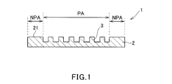
- FIG. 1 is a cut end view showing a schematic configuration of an undifferentiated cell separation substrate according to an embodiment of the present invention.
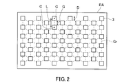
- FIG. 2 is a plan view schematically showing one aspect of an arrangement configuration of a plurality of pillar-like patterns of the undifferentiated cell separation substrate according to the embodiment of the present invention.
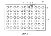
- FIG. 3 is a plan view schematically showing another aspect of the arrangement configuration of a plurality of pillar-like patterns on the undifferentiated cell separation substrate according to one embodiment of the present invention.
- FIG. 4 is a process flow diagram showing the manufacturing process of the undifferentiated cell separation substrate according to the embodiment of the present invention in a cut end view.
- FIG. 1 is a cut end view showing a schematic configuration of an undifferentiated cell separation substrate according to an embodiment of the present invention.
- FIG. 2 is a plan view schematically showing one aspect of an arrangement configuration of a plurality of pillar-like patterns of the undifferentiated cell separation substrate according to the embodiment of the present invention.
- FIG. 3
- FIG. 5 is a plan view showing each region where a pillar-shaped pattern of the test undifferentiated cell separation substrate used in Test Examples 1 and 2 is formed.
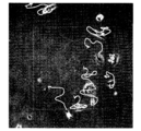
- 6 is a photomicrograph showing an image of mouse-derived mesenchymal stem cells in the vicinity of area PA 34 and a movement locus of mouse-derived mesenchymal stem cells imaged in the evaluation test of Test Example 1.
- FIG. 7 is a photomicrograph showing an image of mouse-derived osteoblasts in the vicinity of area PA 34 and a movement locus of mouse-derived osteoblasts imaged in the evaluation test of Test Example 2.
- FIG. 8 is a photomicrograph showing an image of human-derived mesenchymal stem cells in the vicinity of area PA 34 and a movement trajectory of human-derived mesenchymal stem cells imaged in the evaluation test of Test Example 3.
- FIG. 9 is a photomicrograph showing an image of human-derived osteoblasts in the vicinity of area PA 34 and a movement locus of human-derived osteoblasts imaged in the evaluation test of Test Example 4.
- FIG. 10 is a photomicrograph showing an image of human-derived adipose precursor cells in the vicinity of area PA 24 and a movement locus of human-derived adipose precursor cells imaged in the evaluation test of Test Example 5.
- FIG. 11 is a photomicrograph showing an image of human-derived chondrocytes in the vicinity of area PA 24 and a movement trajectory of human-derived chondrocytes taken in the evaluation test of Test Example 6.
- FIG. 1 is a cut end view showing a schematic configuration of an undifferentiated cell separation substrate according to the present embodiment
- FIG. 2 is an arrangement configuration of a plurality of pillar-shaped patterns of the undifferentiated cell separation substrate according to the present embodiment
- FIG. 3 is a plan view schematically showing another aspect of the arrangement configuration of a plurality of pillar-like patterns of the undifferentiated cell separation substrate according to the present embodiment. is there.
- the undifferentiated cell separation substrate 1 is configured by a nano uneven structure having a base 2 and pillar-like patterns 3 formed on the main surface 21 of the base 2. It is used for separating undifferentiated cells from a cell mixture containing differentiated cells and undifferentiated cells.
- the undifferentiated cells and differentiated cells contained in the cell mixture are not particularly limited as long as they are adhesive cells.
- undifferentiated cells include somatic stem cells, iPS cells, ES cells and the like.
- differentiated cells include neural cells, osteoblasts, vascular endothelial cells, cardiomyocytes, etc., induced to differentiate from the undifferentiated cells.
- the undifferentiated cells are mesenchymal stem cells derived from a mouse and the differentiated cells are osteoblasts induced to differentiate from the undifferentiated cells, the undifferentiated cells are derived from humans.
- Undifferentiated cells can be separated more efficiently.
- Materials constituting the base 2 include quartz glass, synthetic quartz glass, soda glass, fluorite, calcium fluoride, magnesium fluoride, acrylic glass, borosilicate glass, etc .; polycarbonate, polypropylene, polyethylene, polystyrene, etc.
- a transparent material such as a resin material such as polyolefin can be used.
- “transparent” means that when light having a wavelength of 190 to 800 nm is irradiated from one side of an object (base 2 in the present embodiment), the light reaches the opposite side to the irradiated side. Means that. If a suitable standard is expressed by transmittance, it is 20% or more, preferably 50% or more, particularly preferably 80% or more.
- the shape of the base 2 is not particularly limited, and examples thereof include a substantially rectangular shape in plan view and a substantially circular shape in plan view.
- the size of the base 2 in plan view and the thickness of the base 2 are not particularly limited, and can be appropriately set according to the use of the undifferentiated cell separation substrate 1.
- the size of the cell separation substrate 1 in plan view can be set to a size that can be accommodated in the dish.
- the thickness of the undifferentiated cell separation substrate 1 is also set to a thickness that allows the pillar-shaped pattern 3 and the cell mixture to come into contact with each other when the undifferentiated cell separation substrate 1 is placed in the dish. obtain.
- the pillar-shaped pattern 3 has a substantially circular shape or a substantially rectangular shape in plan view, and is arranged with a predetermined regularity in a predetermined area PA on the main surface 21 of the base portion 2 as a structure integrated with the base portion 2. It is formed as follows.
- pillar-shaped patterns 3 having a substantially rectangular shape in plan view may be arranged on each lattice point of a regular triangular lattice Gr, or as shown in FIG. 3, It may be arranged on each lattice point of the square lattice Gr.
- the predetermined area PA where the pillar-shaped pattern 3 is formed is such that the size of the area NPA where the pillar-shaped pattern 3 is not formed on the main surface 21 of the base 2 is as small as possible. It is preferably set on the main surface 21.
- the pillar-shaped pattern 3 in the present embodiment has nano-level gaps G and dimensions D, in particular, they have a predetermined relationship, so that undifferentiated cells and differentiated cells in the cell mixture A difference in adhesion is expressed, and either one of the undifferentiated cells and the differentiated cells is relatively easy to adhere to the pillar-shaped pattern 3, and the other is relatively difficult to adhere to the pillar-shaped pattern 3.
- both undifferentiated cells and differentiated cells adhere to the region NPA where the pillar-shaped pattern 3 is not formed. That is, if the region NPA where the pillar-shaped pattern 3 is not formed is large, there is a possibility that undifferentiated cells cannot be efficiently separated. Therefore, undifferentiated cells can be efficiently separated by making the region NPA where the pillar-shaped pattern 3 is not formed as small as possible.
- the interval G and the dimension D of the pillar-shaped pattern 3 are both preferably in the range of 50 to 500 nm, more preferably in the range of 100 to 250 nm, which is the same size as the cell adhesion complex. preferable.
- a combination of undifferentiated cells and differentiated cells contained in the cell mixture is mouse-derived mesenchymal stem cells and osteoblasts, human-derived mesenchymal stem cells and osteoblasts, human-derived mesenchymal stem cells and adipose precursor cells, or
- the distance G and the dimension D preferably have any of the following relationships (1-1) to (1-7).
- the gap G and the dimension D have any one of the following relationships (1-1 ′) to (1-7 ′).
- the gap G and the dimension D have any one of the following relationships (1-1 ′′) to (1-7 ′′).
- a combination of undifferentiated cells and differentiated cells contained in the cell mixture is mouse-derived mesenchymal stem cells and osteoblasts, human-derived mesenchymal stem cells and osteoblasts, human-derived mesenchymal stem cells and adipose precursor cells,
- the gap G and the dimension D preferably have any one of the following relationships (2-1) to (2-7).
- the gap G and the dimension D have any one of the following relationships (2-1 ′) to (2-7 ′).
- the gap G and the dimension D have any one of the following relationships (2-1 ′′) to (2-7 ′′).
- the interval G and dimension D are the following (3-1) to (3 -7) Any one of the relationships is satisfied.
- the gap G and the dimension D have any one of the following relationships (3-1 ′) to (3-7 ′).
- the gap G and the dimension D have any one of the following relationships (3-1 ′′) to (3-7 ′′).
- the combination of undifferentiated cells and differentiated cells contained in the cell mixture is human-derived mesenchymal stem cells and osteoblasts, human-derived mesenchymal stem cells and adipose precursor cells, or human-derived mesenchymal stem cells and chondrocytes.
- the gap G and the dimension D have any one of the following relationships (4-1) to (4-7).
- the gap G and the dimension D have any one of the following relationships (4-1 ′) to (4-7 ′).
- the gap G and the dimension D have any one of the following relationships (4-1 ′′) to (4-7 ′′).
- the combination of undifferentiated cells and differentiated cells contained in the cell mixture is human-derived mesenchymal stem cells and osteoblasts, human-derived mesenchymal stem cells and adipose precursor cells, and human-derived mesenchymal stem cells and chondrocytes.
- the gap G and the dimension D have any one of the following relationships (5-1) to (5-4).
- the gap G and the dimension D have any one of the following relationships (5-1 ′) to (5-4 ′).
- 115 nm ⁇ D ⁇ 210 nm (5-3 ′) 240 nm ⁇ G ⁇ 250 nm; 240 nm ⁇ D ⁇ 250 nm (5-4 ′)
- the gap G and the dimension D have any one of the following relationships (5-1 ′′) to (5-4 ′′).
- the distance G and the dimension D of the pillar pattern 3 are any one of the above relations (1-1) to (1-7), preferably any one of the relations (1-1 ′) to (1-7 ′). More preferably, any one of the cells (undifferentiated cells or differentiated cells) becomes the pillar-shaped pattern 3 by having any one of the above relationships (1-1 ′′) to (1-7 ′′). The other cell (differentiated cell or undifferentiated cell) becomes relatively difficult to adhere to the pillar-shaped pattern 3 relatively easily.
- the distance G and dimension D of the pillar-shaped pattern 3 are any one of the above relations (2-1) to (2-7), preferably any one of the above relations (2-1 ′) to (2-7 ′). More preferably, by having any one of the above relationships (2-1 ′′) to (2-7 ′′), the undifferentiated cells and the differentiated cells contained in the cell mixture are derived from a mouse. Even if it is a human-derived one, any one cell (undifferentiated cell or differentiated cell) is relatively easy to adhere to the pillar-shaped pattern 3, and the other cell (differentiated cell or undifferentiated cell). Becomes relatively difficult to adhere to the pillar-shaped pattern 3, and versatility is enhanced.
- the interval G and the dimension D of the pillar pattern 3 are related to any one of the above (3-1) to (3-7), Preferably, it has any one of the above relationships (3-1 ′) to (3-7 ′), and more preferably any one of the above relationships (3-1 ′′) to (3-7 ′′).
- undifferentiated cells are relatively easy to adhere to the pillar-shaped pattern 3
- differentiated cells are relatively difficult to adhere to the pillar-shaped pattern 3.
- the interval G and the size of the pillar-shaped pattern 3 D is any one of the above relations (4-1) to (4-7), preferably any one of the above relations (4-1 ′) to (4-7 ′), more preferably the above (4-1 )) To (4-7 ''), so that any one cell (undifferentiated cell or differentiated cell) is relatively easy to adhere to the pillar-shaped pattern 3, and the other Cells (differentiated cells or undifferentiated cells) become relatively difficult to adhere to the pillar-shaped pattern 3.
- the distance G and the dimension D of the pillar-shaped pattern 3 are any one of the above relations (5-1) to (5-4), preferably any one of the above (5-1 ′) to (5-4 ′). More preferably, the undifferentiated cell contained in the cell mixture is a human-derived mesenchymal stem cell by satisfying any of the above relationships (5-1 ′′) to (5-4 ′′).
- any one cell is relatively adhered to the pillar pattern 3
- the other cell is relatively less likely to adhere to the pillar-shaped pattern 3, and versatility is enhanced.
- the pillar-shaped pattern 3 can be obtained simply by bringing the cell mixture and the pillar-shaped pattern 3 into contact using the difference in adhesion between the undifferentiated cells and the differentiated cells contained in the cell mixture.
- Cells that are relatively difficult to adhere to can be suspended in the culture medium.
- the target cell is a cell that is relatively easy to adhere to the pillar-shaped pattern 3
- the cell remaining on the pillar-shaped pattern 3 can be easily separated.
- the target cell is a cell that is relatively difficult to adhere to the pillar pattern 3, the cell can be separated by collecting the culture solution.
- the interval G between the pillar-shaped patterns 3 is “a straight line connecting the center C of the plan view of one pillar-shaped pattern 3 and the center of plan view C of the other pillar-shaped pattern 3 closest thereto. This means the length obtained by subtracting the dimension D of the pillar-shaped pattern from the length L.
- the dimension D of the pillar-shaped pattern 3 is “the length of one side of the square if the pillar-shaped pattern 3 has a substantially square shape in plan view”. If the pillar-shaped pattern 3 has a substantially circular shape in plan view, it means the diameter of the circle ”.
- the height (aspect ratio) of the pillar-shaped pattern 3 is not particularly limited, and can be appropriately set according to the dimension D of the pillar-shaped pattern 3. Usually, the height of the pillar-shaped pattern 3 can be set so that the aspect ratio of the pillar-shaped pattern 3 is about 0.5 to 5.
- the predetermined area PA where the pillar-shaped pattern 3 is formed is set on substantially the entire main surface 21 of the base portion 2, but is not limited to such a mode.
- the main surface 21 of the base portion 2 may be divided into first to Nth regions (N is an integer of 2 or more), and the pillar pattern 3 may be formed in each region.
- the interval G and the dimension D of the pillar pattern 3 may be the same in each region or may be different.
- undifferentiated cell separation substrate 1 having the above-described configuration, as will be apparent from Examples described later, when the cell mixture containing differentiated cells and undifferentiated cells is brought into contact with the pillar pattern 3, One of the undifferentiated cells and the differentiated cells is relatively easy to adhere to the pillar-shaped pattern 3, and the other is relatively difficult to adhere to the pillar-shaped pattern 3. Therefore, undifferentiated cells can be selectively and easily separated from the cell mixture.
- undifferentiated cells remaining on the pillar-shaped pattern 3 can be obtained by using the undifferentiated cell separation substrate 1 having the pillar-shaped pattern 3 in which the undifferentiated cells are relatively easy to adhere in relation to the interval G and the dimension D. It can be selectively and easily separated.
- the undifferentiated cell separation substrate 1 having the pillar-shaped pattern 3 in which the undifferentiated cells are relatively difficult to adhere in relation to the interval G and the dimension D the undifferentiated cells floating in the culture solution are selectively selected. And can be separated easily. Further, unlike the conventional method of separating the undifferentiated cells by detecting the identification labels or the like given to the undifferentiated cells, it is not necessary to give or remove the identification labels or the like. According to the undifferentiated cell separation substrate 1, undifferentiated cells can be separated from the cell mixture with minimal invasiveness.
- mesenchymal stem cells that are undifferentiated cells In the field of regenerative medicine in which mesenchymal stem cells that are undifferentiated cells are administered to a patient, it may be desired to selectively culture only mesenchymal stem cells.
- mesenchymal stem cell culturing step some cells may differentiate into osteoblasts and the like, and unnecessary cells (such as osteoblasts that are differentiated cells) may be mixed.
- unnecessary cells such as osteoblasts which are differentiated cells
- target mesenchymal stem cells are selected. Therefore, mesenchymal stem cells can be cultured at a high cell density because they can be easily separated.
- chondrocytes obtained by differentiating mesenchymal stem cells which are undifferentiated cells
- mesenchymal stem cell culturing step a part of the mesenchymal stem cell may differentiate into an osteoblast.
- the undifferentiated cell separation substrate 1 according to the present embodiment is used, osteoblasts that have been unintentionally differentiated can be removed. Therefore, mesenchymal stem cells are cultured at a high cell density. It becomes possible to proliferate.
- FIG. 4 is a process flow diagram showing the manufacturing process of the undifferentiated cell separation substrate 1 according to this embodiment in a cut end view.
- a substrate 20 including a hard mask layer 30 is prepared, a resist film 40 is formed on the hard mask layer 30 of the substrate 20, and the resist is formed using an electron beam lithography apparatus or the like. A pattern latent image is formed on the film 40.
- the constituent materials of the undifferentiated cell separation substrate 1 according to this embodiment for example, quartz glass, synthetic quartz glass, soda glass, fluorite, calcium fluoride, magnesium fluoride, acrylic glass, borosilicate glass
- a substrate made of a glass material such as polycarbonate, polypropylene, polyethylene, polystyrene, and other transparent resin materials such as polyolefin
- polycarbonate such as polypropylene, polyethylene, polystyrene, and other transparent resin materials such as polyolefin
- the hard mask layer 30 is a layer for forming a hard mask pattern 31 that is used for etching the substrate 20 in a process described later (see FIG. 4D). Therefore, it is made of a material that takes into consideration the etching selectivity with the material constituting the substrate 20.
- the hard mask layer 30 is preferably made of metal chromium or the like.
- the resist material constituting the resist film 40 is not particularly limited, and a conventionally known energy beam sensitive resist material (for example, an electron beam sensitive resist material, an ultraviolet sensitive resist material, etc.) or the like may be used. it can.
- a conventionally known energy beam sensitive resist material for example, an electron beam sensitive resist material, an ultraviolet sensitive resist material, etc.
- the pattern latent image formed on the resist film 40 is formed with substantially the same spacing and dimension as the spacing G and dimension D of the pillar-shaped pattern 3 in the undifferentiated cell separation substrate 1.
- the resist film 40 is developed to form a resist pattern 41.
- the hard mask layer 30 is formed using the resist pattern 41 as a mask.
- the hard mask pattern 31 is formed by etching.
- the substrate 20 is etched using the hard mask pattern 31 as a mask to form pillar-like patterns 3 in a predetermined area PA of the main surface 21 of the substrate 20, and finally the hard mask By peeling the pattern 31, the undifferentiated cell separation substrate 1 having the base portion 2 and the pillar-like pattern 3 formed on the main surface 21 of the base portion 2 is manufactured as shown in FIG. Can do.
- the undifferentiated cell separation substrate 1 having the above-described configuration, when the pillar pattern 3 is brought into contact with a cell mixture containing undifferentiated cells and differentiated cells, either one of the undifferentiated cells and the differentiated cells becomes a pillar shape. It is easy to adhere to the pattern 3 and the other is difficult to adhere to the pillar pattern 3.
- the undifferentiated cell separation substrate 1 according to the present embodiment has an effect that the undifferentiated cells can be selectively separated easily and with minimal invasiveness. It can be suitably used in a method for separating differentiated cells.
- the undifferentiated cell separation substrate 1 As a method of bringing the pillar-shaped pattern 3 of the undifferentiated cell separation substrate 1 into contact with the cell mixture, for example, the undifferentiated cell separation substrate 1 is placed in a dish, and the dish Examples thereof include a method of bringing the pillar pattern 3 into contact with the cell mixture by seeding the cell mixture therein.
- the time for bringing the pillar-shaped pattern 3 into contact with the cell mixture selectively separates the undifferentiated cells. There is no particular limitation as long as the time is sufficient.
- either one of the undifferentiated cells and the differentiated cells is a pillar-shaped pattern. It is easy to adhere to 3 and the other is difficult to adhere to the pillar-shaped pattern 3. Therefore, undifferentiated cells can be selectively and easily separated from the cell mixture containing undifferentiated cells and differentiated cells easily and with minimal invasiveness.
- the undifferentiated cell separation substrate 1 having the pillar-like pattern 3 formed as an integral uneven structure on the main surface 21 of the base portion 2 has been described as an example. It is not limited to the embodiment.
- the undifferentiated cell separation substrate 1 has a concavo-convex structure (for example, a sheet having the pillar-shaped pattern 3) having the pillar-shaped pattern 3 configured as a member separate from the base 2 on the main surface 21 of the base 2. A member etc. may be attached.
- the pillar-shaped pattern 3 is formed by etching, and then the hard mask pattern 31 is peeled off to manufacture the undifferentiated cell separation substrate 1, but the present invention is limited to such an embodiment. It is not something.
- the base 2 on which the pillar-shaped pattern 3 is formed may be thinned without changing the dimensions and height of the pillar-shaped pattern 3.
- the undifferentiated cell separation substrate 1 may be manufactured by forming pillar-like patterns 3 in a plurality of regions on the base 2 and cutting (dividing into pieces) for each region.
- a quartz glass substrate (152 mm ⁇ 152 mm, thickness: 6.35 mm) is prepared as a substrate 20 on which a hard mask layer 30 made of Cr having a thickness of 6 nm is provided on the main surface 21, and an electron beam sensitive resist (product) Name: SEBP-9902, manufactured by Shin-Etsu Chemical Co., Ltd.) was applied onto the hard mask layer 30 to form a resist film 40.
- a pillar-shaped resist pattern 41 was formed on the resist film 40 using an electron beam drawing apparatus. The pillar-shaped resist pattern 41 is formed so as to be positioned on each lattice point of the equilateral triangular lattice Gr as shown in FIG.
- 49 divided areas PA 01 to PA 49 are set in a 14 mm ⁇ area PA on the main surface 21 of the quartz glass substrate 20. Then, pillar-shaped resist patterns 41 having different distances G and dimensions D were formed (see FIG. 5).
- the hard mask layer 30 was dry-etched (etching gas: Cl 2 + O 2 ) using the resist pattern 41 as a mask, and the remaining resist pattern 41 was removed to form the hard mask pattern 31.
- the quartz glass substrate 20 is etched using the hard mask pattern 31 formed as described above as a mask, and the pillar-shaped pattern 3 having a predetermined gap G and dimension D is formed in each region of the main surface 21 of the quartz glass substrate 20. Formed. Finally, the hard mask pattern 31 was peeled off to produce a test undifferentiated cell separation substrate (see FIG. 5).
- the interval G and dimension D of the pillar-shaped pattern 3 formed in each of the regions PA 01 to PA 49 of the test undifferentiated cell separation substrate were measured using a scanning electron microscope (product name: LWM9000). The results were as shown in Table 1 below.
- Test Example 1 Prepare a perforated dish (35 mm ⁇ ) with a 14 mm ⁇ hole formed on the bottom surface, and make sure that the areas PA 01 to PA 49 where the pillar-shaped pattern 3 is formed are exposed from the bottom hole.
- the differentiated cell separation substrate was attached to the outside of the bottom surface of the perforated dish.
- mouse-derived mesenchymal stem cells (RIKEN BRC, undifferentiated cells) are seeded in the perforated dish, and the undifferentiated cells are brought into contact with the pillar-shaped pattern 3 of the test undifferentiated cell separation substrate. It was. POWEREDBY10 (manufactured by Glyco Technica) was used as the culture solution.
- An evaluation test was performed to evaluate the relationship between the spacing G and dimension D of the pillar-shaped pattern 3 and the state of cell adhesion based on an image obtained by imaging the vicinity of each region PA 01 to PA 49 36 hours after cell seeding.
- the cell number ratio PMU was evaluated as an index of affinity with respect to the pillar-shaped pattern 3.
- FIG. 6 shows an image of the mesenchymal stem cells in the vicinity of the area PA 34 imaged in the evaluation test and the movement trajectory of the mesenchymal stem cells.
- the arrow line shown in FIG. 6 represents the movement trajectory of the mesenchymal stem cell.
- Test Example 2 The cell number ratio P MD (in each region PA 01 to PA 49 ) was the same as in Test Example 1 except that osteoblasts (differentiated cells) obtained by inducing differentiation of mouse mesenchymal stem cells were seeded in the dish.
- PMD N in / (N in + N out ), N in is “the number of cells existing in each region PA 01 to PA 49 (on the pillar pattern 3) and at the boundary between each region PA 01 to PA 49 ”.
- N out is by calculating the.) representing "an area of the same area as each area PA 01 ⁇ PA 49, the number of cells present in the area surrounding the periphery of each region PA 01 ⁇ PA 49"
- An evaluation test was performed to evaluate the relationship between the distance G and dimension D of the pillar-shaped pattern 3 and the state of cell adhesion. The evaluation results are shown in Table 2.
- FIG. 7 shows an image of osteoblasts in the vicinity of the area PA 34 imaged in the evaluation test and a movement locus of the osteoblasts.
- the arrow line shown in FIG. 7 represents the movement locus
- N in is “the number of cells existing in each region PA 01 to PA 49 (on the pillar-shaped pattern 3) and the boundary between each region PA 01 to PA 49 ”, and N out is “each region a region of the same area as the PA 01 ⁇ PA 49, representing the number "of cells present in the area surrounding the periphery of each region PA 01 ⁇ PA 49.) by calculating the spacing of the pillar-shaped patterns 3
- An evaluation test was performed to evaluate the relationship between G and dimension D and the state of cell adhesion. The evaluation results are shown in Table 2.
- FIG. 8 shows an image of mesenchymal stem cells in the vicinity of the area PA 34 imaged in the evaluation test and a movement locus of the mesenchymal stem cells.
- the arrow line shown in FIG. 8 represents the movement trajectory of the mesenchymal stem cell.
- the cell number ratio P HO in each region PA 01 to PA 49 is the same as in Test Example 1 except that osteoblasts (differentiated cells) obtained by inducing differentiation of human-derived mesenchymal stem cells are seeded in the dish.
- P HO N in / (N in + N out )
- N in is “the number of cells existing in each region PA 01 to PA 49 (on the pillar pattern 3) and at the boundary between each region PA 01 to PA 49 ”.
- N out is by calculating the.) representing "an area of the same area as each area PA 01 ⁇ PA 49, the number of cells present in the area surrounding the periphery of each region PA 01 ⁇ PA 49"
- An evaluation test was performed to evaluate the relationship between the distance G and dimension D of the pillar-shaped pattern 3 and the state of cell adhesion. The evaluation results are shown in Table 2.
- FIG. 9 shows an image of osteoblasts in the vicinity of the area PA 34 imaged in the evaluation test and the movement locus of the osteoblasts.
- the arrow line shown in FIG. 9 represents the movement locus
- Test Example 5 In the same manner as in Test Example 1, except that adipose precursor cells (differentiated cells) obtained by inducing differentiation of human mesenchymal stem cells were seeded in a dish, and Adipogenic Maintenance Medium (manufactured by Lonza) was used as a medium,
- the evaluation test which evaluates the relationship between the space
- Test Example 6 In the same manner as in Test Example 1 except that chondrocytes (differentiated cells) obtained by inducing differentiation of human-derived mesenchymal stem cells were seeded in a dish and Chondrocyte Growth Medium (manufactured by PromoCell) was used as a medium.
- chondrocytes differentiated cells obtained by inducing differentiation of human-derived mesenchymal stem cells were seeded in a dish and Chondrocyte Growth Medium (manufactured by PromoCell) was used as a medium.
- FIG. 11 shows an image of chondrocytes in the vicinity of the area PA 24 and the movement trajectory of the chondrocytes taken in the evaluation test.
- the arrow line shown in FIG. 11 represents the movement locus
- E HAU and selective evaluation A HAD of selective separability of adipose precursor cells estimated from the contact of the P-like pattern 3 with human-derived mesenchymal stem cells It shows together with Table 4.
- the mesenchymal stem cell In the region having the pillar-like pattern 3 having a relatively high capture efficiency E MD and E HOD of the mesenchymal stem cell (the region where the overall evaluation shown in Table 4 is “ ⁇ ” or “ ⁇ ”), the mesenchymal stem cell Then, since the mesenchymal stem cells in the cell mixture containing osteoblasts induced to differentiate are relatively easily adhered to the pillar-shaped pattern 3, the cell mixture is simply brought into contact with the pillar-shaped pattern 3. It is considered that mesenchymal stem cells can be selectively and easily separated and obtained from the cells, or the cell density of mesenchymal stem cells can be increased.
- the pillar-like pattern 3 having relatively high capture efficiency E MD , E HOD , E HAD , E HCD of differentiated cells (osteoblasts, adipose precursor cells, chondrocytes, etc.) induced to differentiate from mesenchymal stem cells
- the differentiated cells in the cell mixture containing the mesenchymal stem cells and the differentiated cells differentiated therefrom are relative to the pillar pattern 3. Therefore, mesenchymal stem cells can be selectively and easily separated and obtained from the cell mixture only by contacting the cell mixture with the pillar-shaped pattern 3, or the mesenchymal system It is thought that the cell density of stem cells can be increased.
- cell adhesion is achieved by using the undifferentiated cell separation substrate 1 on which the pillar-shaped pattern 3 having the distance G and the dimension D having the relationships shown in the following (1-1) to (1-7) is formed. Based on the difference in sex, undifferentiated cells can be selectively and easily separated and obtained from the cell mixture, or the cell density of undifferentiated cells can be increased.
- the undifferentiated cell separation substrate 1 on which the pillar-shaped pattern 3 having the distance G and the dimension D having the relationships shown in the following (2-1) to (2-7) is formed Regardless of the type, it is possible to selectively and easily separate and acquire undifferentiated cells from a cell mixture or increase the cell density of undifferentiated cells based on the difference in cell adhesion.
- the undifferentiated cells contained in the cell mixture are mouse-derived mesenchymal stem cells and the differentiated cells are osteoblasts induced to differentiate therefrom, preferably the following (3-1) to (3-7)
- the undifferentiated cells are selectively selected from the cell mixture based on the difference in cell adhesion. And can be easily separated and obtained, or the cell density of undifferentiated cells can be increased.
- the undifferentiated cells contained in the cell mixture are human-derived mesenchymal stem cells and the differentiated cells are osteoblasts, adipose precursor cells or chondrocytes induced to differentiate therefrom, preferably the following (4-1) to
- the undifferentiated cell separation substrate 1 on which the pillar-shaped pattern 3 having the distance G and the dimension D having the relationship shown in (4-7) is formed it is possible to remove the cell mixture from the cell mixture.
- Undifferentiated cells can be selectively and easily separated and obtained, or the cell density of undifferentiated cells can be increased.
- the cell mixture is particularly preferably used by using the undifferentiated cell separation substrate 1 on which the pillar-shaped pattern 3 having the distance G and the dimension D having the relationships shown in the following (5-1) to (5-4) is formed.
- the undifferentiated cells contained in the cells are human-derived mesenchymal stem cells and the differentiated cells are differentiated from osteoblasts, adipose precursor cells, and chondrocytes, the difference in cell adhesion Based on the above, it is possible to selectively and easily separate and acquire undifferentiated cells from the cell mixture, or to increase the cell density of undifferentiated cells.
- the undifferentiated cells are selectively selected from the cell mixture, and It can be easily separated and obtained, or the cell density of undifferentiated cells can be increased.
- the present invention is useful in technical fields related to regenerative medicine using undifferentiated cells or differentiated cells.
Landscapes
- Life Sciences & Earth Sciences (AREA)
- Engineering & Computer Science (AREA)
- Health & Medical Sciences (AREA)
- Wood Science & Technology (AREA)
- Biomedical Technology (AREA)
- Organic Chemistry (AREA)
- Bioinformatics & Cheminformatics (AREA)
- Chemical & Material Sciences (AREA)
- Zoology (AREA)
- Virology (AREA)
- Sustainable Development (AREA)
- Microbiology (AREA)
- Biotechnology (AREA)
- Biochemistry (AREA)
- General Engineering & Computer Science (AREA)
- General Health & Medical Sciences (AREA)
- Genetics & Genomics (AREA)
- Cell Biology (AREA)
- Micro-Organisms Or Cultivation Processes Thereof (AREA)
- Apparatus Associated With Microorganisms And Enzymes (AREA)
Abstract
未分化細胞と分化細胞とを含む細胞混合物から未分化細胞を分離する方法は、複数のピラー状パターンが規則性を有して配列されてなるナノ凹凸構造体を用い、複数のピラー状パターンに細胞混合物を接触させる工程を含み、ピラー状パターンの間隔Gと寸法Dとが、未分化細胞及び分化細胞のうちのいずれか一方がピラー状パターンに接着し易く、他方がピラー状パターンに接着し難い関係を具備する。これにより、未分化細胞と分化細胞とを含む細胞混合物から分化細胞を選択的に、かつ容易に分離することができる。
Description
本発明は、未分化細胞と分化細胞とを含む細胞混合物から当該未分化細胞を分離する方法及び当該未分化細胞を分離するために用いられる基板に関する。
体性幹細胞、iPS細胞、ES細胞等に代表される幹細胞は、神経細胞、骨芽細胞、血管内皮細胞、心筋細胞等の様々な機能を有する細胞への分化能を有する。そのため、幹細胞を分化誘導させることで得られる神経細胞、骨芽細胞、血管内皮細胞、心筋細胞等を用いて生体の細胞、組織、器官等を再構築する再生医療分野への応用が期待されている。
幹細胞の再生医療分野への応用研究にあたり、幹細胞と、当該幹細胞から分化誘導した分化細胞(神経細胞、骨芽細胞、血管内皮細胞、心筋細胞等)とを含む細胞混合物から、未分化の幹細胞を分離・取得するのが望ましい場合がある。未分化細胞を分化誘導させる際に、分化細胞が混在していると、未分化細胞の分化誘導の効率が低下することがある。また、そのようにして分化誘導した細胞を、例えば組織形成に使用する場合、組織形成不全が起こるおそれがある。そのため、当該細胞混合物から分化細胞を除去し、未分化細胞を分離・取得することが重要となる。
一方で、未分化細胞と分化細胞とを含む細胞混合物を使用した組織形成が可能であるとの報告もある(非特許文献1参照)。この場合において、細胞混合物中における未分化細胞の細胞密度が適切な範囲に調整されていることが重要となる。
従来、所定の目的細胞を含む細胞混合物から当該目的細胞を分離する方法として、細胞混合物に含まれる目的細胞とその他の細胞との大きさの違いに着目し、当該目的細胞を捕捉可能なフィルタを備える分離装置を用いて分離する方法(特許文献1参照)、分離目的細胞に識別ラベル等を付加し、当該識別ラベル等を検出することにより目的細胞を分離する方法(特許文献2,特許文献3,非特許文献2参照)等が知られている。
Takabe et al., "Vascularized and Complex Organ Buds from Diverse Tissues via Mesenchymal Cell-Driven Condensation", Cell Stem Cell, Vol. 16, pp. 556-565, 2015
Kuanyin K. Lin et al., "Detection of Hematopoietic Stem Cells by Flow Cytometry", METHODS IN CELLS BIOLOGY, Vol. 103, 2011
特許文献1に記載の分離方法は、細胞混合物に含まれる目的細胞の大きさと、細胞混合物に含まれる他の細胞の大きさとに応じて、目的細胞を捕捉可能なフィルタを用いることにより、当該目的細胞を分離する方法である。したがって、細胞混合物に含まれる所定の目的細胞の大きさが、当該細胞混合物に含まれる他の細胞の大きさと異なる場合には、当該目的細胞を分離することができる。しかしながら、未分化細胞と分化細胞との大きさは実質的に同一であるため、上記分離方法を用いても、上記細胞混合物から未分化細胞を完全に分離・取得することができず、一方(例えば未分化細胞)の細胞密度を向上させることも困難であるという問題がある。
また、特許文献2、特許文献3及び非特許文献2に記載の分離方法を用いて細胞混合物中の未分化細胞を分離するためには、細胞混合物中の未分化細胞に識別ラベル等を付与する必要があり、当該識別ラベル等の検出により未分化細胞を分離することが可能な方法ではある。しかし、分離された未分化細胞を分化誘導して得られる分化細胞を用いて組織形成を行うためには、分離後の未分化細胞から識別ラベル等を除去しなければならない場合があるが、識別ラベル等の未分化細胞への付与及び除去操作により、当該未分化細胞に損傷を与えてしまうおそれがある。また、かかる識別ラベル等の付与・除去作業が煩雑であるという問題もある。
このような課題に鑑みて、本発明は、未分化細胞と分化細胞とを含む細胞混合物から未分化細胞を選択的に、容易に、かつ低侵襲で分離することのできる方法及び当該分離方法に用いられる未分化細胞分離用基板を提供することを目的とする。
上記課題を解決するために、本発明は、未分化細胞と分化細胞とを含む細胞混合物から前記未分化細胞を分離する方法であって、複数のピラー状パターンが規則性を有して配列されてなるナノ凹凸構造体を用い、前記複数のピラー状パターンに前記細胞混合物を接触させる工程を含み、前記ピラー状パターンの間隔Gと寸法Dとが、前記未分化細胞及び前記分化細胞のうちのいずれか一方が前記ピラー状パターンに接着し易く、他方が前記ピラー状パターンに接着し難い関係を具備することを特徴とする未分化細胞の分離方法を提供する(発明1)。
本発明者らの鋭意研究により、ナノ凹凸構造体に複数のピラー状パターンが規則性を有して配列されていることで、当該ナノ凹凸構造体の複数のピラー状パターンが配列されている領域において、未分化細胞と分化細胞とのピラー状パターンに対する接着性に違いが生じることが見出された。よって、上記発明(発明1)によれば、未分化細胞と分化細胞とを含む細胞混合物から未分化細胞を選択的に、容易に、かつ低侵襲で分離することができる。
なお、本発明において、ピラー状パターンの間隔とは、「一のピラー状パターンの平面視中心と、それに隣接する他のピラー状パターンの平面視中心とを結ぶ直線長さからピラー状パターンの寸法を差し引いた長さ」を意味し、ピラー状パターンの寸法とは、「平面視略正方形状のピラー状パターンであれば当該正方形の一辺の長さ、平面視略円形状のピラー状パターンであれば当該円の直径」を意味する。また、本発明において「分離」とは、少なくとも2種の細胞(例えば、未分化細胞及び分化細胞)を含む細胞混合物から、いずれか一方の細胞(例えば、未分化細胞)を完全に分離・取得することに限らず、当該細胞混合物中におけるいずれか一方の細胞(例えば、未分化細胞)の細胞密度を高めることをも意味するものとする。
上記発明(発明1)においては、前記ピラー状パターンの間隔Gと寸法Dとが、いずれも50~500nmの範囲内であるのが好ましく(発明2)、いずれも100~250nmの範囲内であるのが好ましい(発明3)。
上記発明(発明1~3)において、前記ピラー状パターンの間隔Gと寸法Dとが、下記(1-1)~(1-7)のいずれかの関係を有していてもよい(発明4)。
100nm≦G<112.5nm;100nm≦D≦250nm …(1-1)
112.5nm≦G<137.5nm;112.5nm≦D≦250nm …(1-2)
137.5nm≦G<162.5nm;100nm≦D≦250nm …(1-3)
162.5nm≦G<187.5nm;112.5nm≦D≦250nm …(1-4)
187.5nm≦G<212.5nm;100nm≦D<187.5nm又は212.5nm≦D≦250nm …(1-5)
212.5nm≦G<237.5nm;100nm≦D<137.5nm又は212.5nm≦D≦250nm …(1-6)
237.5nm≦G≦250nm;100nm≦D≦250nm …(1-7)
100nm≦G<112.5nm;100nm≦D≦250nm …(1-1)
112.5nm≦G<137.5nm;112.5nm≦D≦250nm …(1-2)
137.5nm≦G<162.5nm;100nm≦D≦250nm …(1-3)
162.5nm≦G<187.5nm;112.5nm≦D≦250nm …(1-4)
187.5nm≦G<212.5nm;100nm≦D<187.5nm又は212.5nm≦D≦250nm …(1-5)
212.5nm≦G<237.5nm;100nm≦D<137.5nm又は212.5nm≦D≦250nm …(1-6)
237.5nm≦G≦250nm;100nm≦D≦250nm …(1-7)
上記発明(発明1~3)において、前記ピラー状パターンの間隔Gと寸法Dとが、下記(2-1)~(2-7)のいずれかの関係を有していてもよい(発明5)。
100nm≦G<112.5nm;112.5nm≦D≦250nm …(2-1)
112.5nm≦G<137.5nm;112.5nm≦D<137.5nm …(2-2)
137.5nm≦G<162.5nm;112.5nm≦D<162.5nm又は187.5nm≦D<237.5nm …(2-3)
162.5nm≦G<187.5nm;162.5nm≦D<212.5nm又は237.5nm≦D≦250nm …(2-4)
187.5nm≦G<212.5nm;212.5nm≦D<237.5nm …(2-5)
212.5nm≦G<237.5nm;237.5nm≦D≦250nm …(2-6)
237.5nm≦G≦250nm;162.5nm≦D<237.5nm …(2-7)
100nm≦G<112.5nm;112.5nm≦D≦250nm …(2-1)
112.5nm≦G<137.5nm;112.5nm≦D<137.5nm …(2-2)
137.5nm≦G<162.5nm;112.5nm≦D<162.5nm又は187.5nm≦D<237.5nm …(2-3)
162.5nm≦G<187.5nm;162.5nm≦D<212.5nm又は237.5nm≦D≦250nm …(2-4)
187.5nm≦G<212.5nm;212.5nm≦D<237.5nm …(2-5)
212.5nm≦G<237.5nm;237.5nm≦D≦250nm …(2-6)
237.5nm≦G≦250nm;162.5nm≦D<237.5nm …(2-7)
上記発明(発明1~3)において、前記ピラー状パターンの間隔Gと寸法Dとが、下記(3-1)~(3-7)のいずれかの関係を有していてもよい(発明6)。
100nm≦G<112.5nm;112.5nm≦D≦250nm …(3-1)
112.5nm≦G<137.5nm;112.5nm≦D<137.5nm …(3-2)
137.5nm≦G<162.5nm;100nm≦D<162.5nm又は187.5nm≦D≦250nm …(3-3)
162.5nm≦G<187.5nm;162.5nm≦D<212.5nm又は237.5nm≦D≦250nm …(3-4)
187.5nm≦G<212.5nm;212.5nm≦D<237.5nm …(3-5)
212.5nm≦G<237.5nm;100nm≦D<112.5nm又は237.5nm≦D≦250nm …(3-6)
237.5nm≦G≦250nm;100nm≦D<137.5nm又は162.5nm≦D<237.5nm …(3-7)
100nm≦G<112.5nm;112.5nm≦D≦250nm …(3-1)
112.5nm≦G<137.5nm;112.5nm≦D<137.5nm …(3-2)
137.5nm≦G<162.5nm;100nm≦D<162.5nm又は187.5nm≦D≦250nm …(3-3)
162.5nm≦G<187.5nm;162.5nm≦D<212.5nm又は237.5nm≦D≦250nm …(3-4)
187.5nm≦G<212.5nm;212.5nm≦D<237.5nm …(3-5)
212.5nm≦G<237.5nm;100nm≦D<112.5nm又は237.5nm≦D≦250nm …(3-6)
237.5nm≦G≦250nm;100nm≦D<137.5nm又は162.5nm≦D<237.5nm …(3-7)
上記発明(発明1~3)において、前記ピラー状パターンの間隔Gと寸法Dとが、下記(4-1)~(4-7)のいずれかの関係を有していてもよい(発明7)。
100nm≦G<112.5nm;100nm≦D≦250nm …(4-1)
112.5nm≦G<137.5nm;112.5nm≦D≦250nm …(4-2)
137.5nm≦G<162.5nm;112.5nm≦D≦250nm …(4-3)
162.5nm≦G<187.5nm;112.5nm≦D≦250nm …(4-4)
187.5nm≦G<212.5nm;100nm≦D<187.5nm又は212.5nm≦D≦250nm …(4-5)
212.5nm≦G<237.5nm;100nm≦D<137.5nm又は212.5nm≦D≦250nm …(4-6)
237.5nm≦G≦250nm;137.5nm≦D≦250nm …(4-7)
100nm≦G<112.5nm;100nm≦D≦250nm …(4-1)
112.5nm≦G<137.5nm;112.5nm≦D≦250nm …(4-2)
137.5nm≦G<162.5nm;112.5nm≦D≦250nm …(4-3)
162.5nm≦G<187.5nm;112.5nm≦D≦250nm …(4-4)
187.5nm≦G<212.5nm;100nm≦D<187.5nm又は212.5nm≦D≦250nm …(4-5)
212.5nm≦G<237.5nm;100nm≦D<137.5nm又は212.5nm≦D≦250nm …(4-6)
237.5nm≦G≦250nm;137.5nm≦D≦250nm …(4-7)
上記発明(発明1~3)において、前記ピラー状パターンの間隔Gと寸法Dとが、下記(5-1)~(5-4)のいずれかの関係を有していてもよい(発明8)。
112.5nm≦G<137.5nm;187.5nm≦D<212.5nm …(5-1)
137.5nm≦G<162.5nm;112.5nm≦D<137.5nm …(5-2)
162.5nm≦G<187.5nm;112.5nm≦D<212.5nm …(5-3)
237.5nm≦G≦250nm;237.5nm≦D≦250nm …(5-4)
112.5nm≦G<137.5nm;187.5nm≦D<212.5nm …(5-1)
137.5nm≦G<162.5nm;112.5nm≦D<137.5nm …(5-2)
162.5nm≦G<187.5nm;112.5nm≦D<212.5nm …(5-3)
237.5nm≦G≦250nm;237.5nm≦D≦250nm …(5-4)
上記発明(発明1~6)において、前記未分化細胞が、マウスに由来する間葉系幹細胞であり、前記分化細胞が、前記未分化細胞から分化した骨芽細胞であるのが好ましい(発明9)。
上記発明(発明1~5、7,8)において、前記未分化細胞が、ヒトに由来する間葉系幹細胞であるのが好ましい(発明10)。
上記発明(発明1~10)において、前記凹凸構造体は、前記複数のピラー状パターンが正三角形格子の各格子点上に配列されていてもよいし(発明11)、前記複数のピラー状パターンが方形格子の各格子点上に配列されていてもよい(発明12)。
また、本発明は、未分化細胞と分化細胞とを含む細胞混合物から前記未分化細胞を分離するために用いられる未分化細胞分離用基板であって、第1面及び前記第1面に対向する第2面を有する基材と、前記基材の前記第1面に規則性を有して配列形成されてなる複数のピラー状ナノパターンとを備え、前記ピラー状ナノパターンの間隔Gと寸法Dとが、前記未分化細胞及び前記分化細胞のうちのいずれか一方が前記ピラー状ナノパターンに接着し易く、他方が前記ピラー状ナノパターンに接着し難い関係を具備することを特徴とする未分化細胞分離用基板を提供する(発明13)。
上記発明(発明13)において、前記ピラー状ナノパターンの間隔Gと寸法Dとが、いずれも50~500nmの範囲内であるのが好ましく(発明14)、前記ピラー状パターンの間隔Gと寸法Dとが、いずれも100~250nmの範囲内であるのが好ましい(発明15)。
上記発明(発明13~15)において、前記ピラー状パターンの間隔Gと寸法Dとが、下記(1-1)~(1-7)のいずれかの関係を有していてもよい(発明16)。
100nm≦G<112.5nm;100nm≦D≦250nm …(1-1)
112.5nm≦G<137.5nm;112.5nm≦D≦250nm …(1-2)
137.5nm≦G<162.5nm;100nm≦D≦250nm …(1-3)
162.5nm≦G<187.5nm;112.5nm≦D≦250nm …(1-4)
187.5nm≦G<212.5nm;100nm≦D<187.5nm又は212.5nm≦D≦250nm …(1-5)
212.5nm≦G<237.5nm;100nm≦D<137.5nm又は212.5nm≦D≦250nm …(1-6)
237.5nm≦G≦250nm;100nm≦D≦250nm …(1-7)
100nm≦G<112.5nm;100nm≦D≦250nm …(1-1)
112.5nm≦G<137.5nm;112.5nm≦D≦250nm …(1-2)
137.5nm≦G<162.5nm;100nm≦D≦250nm …(1-3)
162.5nm≦G<187.5nm;112.5nm≦D≦250nm …(1-4)
187.5nm≦G<212.5nm;100nm≦D<187.5nm又は212.5nm≦D≦250nm …(1-5)
212.5nm≦G<237.5nm;100nm≦D<137.5nm又は212.5nm≦D≦250nm …(1-6)
237.5nm≦G≦250nm;100nm≦D≦250nm …(1-7)
上記発明(発明13~15)において、前記ピラー状パターンの間隔Gと寸法Dとが、下記(2-1)~(2-7)のいずれかの関係を有していてもよい(発明17)。
100nm≦G<112.5nm;112.5nm≦D≦250nm …(2-1)
112.5nm≦G<137.5nm;112.5nm≦D<137.5nm …(2-2)
137.5nm≦G<162.5nm;112.5nm≦D<162.5nm又は187.5nm≦D<237.5nm …(2-3)
162.5nm≦G<187.5nm;162.5nm≦D<212.5nm又は237.5nm≦D≦250nm …(2-4)
187.5nm≦G<212.5nm;212.5nm≦D<237.5nm …(2-5)
212.5nm≦G<237.5nm;237.5nm≦D≦250nm …(2-6)
237.5nm≦G≦250nm;162.5nm≦D<237.5nm …(2-7)
100nm≦G<112.5nm;112.5nm≦D≦250nm …(2-1)
112.5nm≦G<137.5nm;112.5nm≦D<137.5nm …(2-2)
137.5nm≦G<162.5nm;112.5nm≦D<162.5nm又は187.5nm≦D<237.5nm …(2-3)
162.5nm≦G<187.5nm;162.5nm≦D<212.5nm又は237.5nm≦D≦250nm …(2-4)
187.5nm≦G<212.5nm;212.5nm≦D<237.5nm …(2-5)
212.5nm≦G<237.5nm;237.5nm≦D≦250nm …(2-6)
237.5nm≦G≦250nm;162.5nm≦D<237.5nm …(2-7)
上記発明(発明13~15)において、前記ピラー状パターンの間隔Gと寸法Dとが、下記(3-1)~(3-7)のいずれかの関係を有していてもよい(発明18)。
100nm≦G<112.5nm;112.5nm≦D≦250nm …(3-1)
112.5nm≦G<137.5nm;112.5nm≦D<137.5nm …(3-2)
137.5nm≦G<162.5nm;100nm≦D<162.5nm又は187.5nm≦D≦250nm …(3-3)
162.5nm≦G<187.5nm;162.5nm≦D<212.5nm又は237.5nm≦D≦250nm …(3-4)
187.5nm≦G<212.5nm;212.5nm≦D<237.5nm …(3-5)
212.5nm≦G<237.5nm;100nm≦D<112.5nm又は237.5nm≦D≦250nm …(3-6)
237.5nm≦G≦250nm;100nm≦D<137.5nm又は162.5nm≦D<237.5nm …(3-7)
100nm≦G<112.5nm;112.5nm≦D≦250nm …(3-1)
112.5nm≦G<137.5nm;112.5nm≦D<137.5nm …(3-2)
137.5nm≦G<162.5nm;100nm≦D<162.5nm又は187.5nm≦D≦250nm …(3-3)
162.5nm≦G<187.5nm;162.5nm≦D<212.5nm又は237.5nm≦D≦250nm …(3-4)
187.5nm≦G<212.5nm;212.5nm≦D<237.5nm …(3-5)
212.5nm≦G<237.5nm;100nm≦D<112.5nm又は237.5nm≦D≦250nm …(3-6)
237.5nm≦G≦250nm;100nm≦D<137.5nm又は162.5nm≦D<237.5nm …(3-7)
上記発明(発明13~15)において、前記ピラー状パターンの間隔Gと寸法Dとが、下記(4-1)~(4-7)のいずれかの関係を有していてもよい(発明19)。
100nm≦G<112.5nm;100nm≦D≦250nm …(4-1)
112.5nm≦G<137.5nm;112.5nm≦D≦250nm …(4-2)
137.5nm≦G<162.5nm;112.5nm≦D≦250nm …(4-3)
162.5nm≦G<187.5nm;112.5nm≦D≦250nm …(4-4)
187.5nm≦G<212.5nm;100nm≦D<187.5nm又は212.5nm≦D≦250nm …(4-5)
212.5nm≦G<237.5nm;100nm≦D<137.5nm又は212.5nm≦D≦250nm …(4-6)
237.5nm≦G≦250nm;137.5nm≦D≦250nm …(4-7)
100nm≦G<112.5nm;100nm≦D≦250nm …(4-1)
112.5nm≦G<137.5nm;112.5nm≦D≦250nm …(4-2)
137.5nm≦G<162.5nm;112.5nm≦D≦250nm …(4-3)
162.5nm≦G<187.5nm;112.5nm≦D≦250nm …(4-4)
187.5nm≦G<212.5nm;100nm≦D<187.5nm又は212.5nm≦D≦250nm …(4-5)
212.5nm≦G<237.5nm;100nm≦D<137.5nm又は212.5nm≦D≦250nm …(4-6)
237.5nm≦G≦250nm;137.5nm≦D≦250nm …(4-7)
上記発明(発明13~15)において、前記ピラー状パターンの間隔Gと寸法Dとが、下記(5-1)~(5-4)のいずれかの関係を有していてもよい(発明20)。
112.5nm≦G<137.5nm;187.5nm≦D<212.5nm …(5-1)
137.5nm≦G<162.5nm;112.5nm≦D<137.5nm …(5-2)
162.5nm≦G<187.5nm;112.5nm≦D<212.5nm …(5-3)
237.5nm≦G≦250nm;237.5nm≦D≦250nm …(5-4)
112.5nm≦G<137.5nm;187.5nm≦D<212.5nm …(5-1)
137.5nm≦G<162.5nm;112.5nm≦D<137.5nm …(5-2)
162.5nm≦G<187.5nm;112.5nm≦D<212.5nm …(5-3)
237.5nm≦G≦250nm;237.5nm≦D≦250nm …(5-4)
上記発明(発明13~18)において、前記未分化細胞が、マウスに由来する間葉系幹細胞であり、前記分化細胞が、前記未分化細胞から分化した骨芽細胞であるのが好ましい(発明21)。
上記発明(発明13~17,19,20)において、前記未分化細胞が、ヒトに由来する間葉系幹細胞であるのが好ましい(発明22)。
上記発明(発明13~22)において、前記複数のピラー状パターンは、正三角形格子の各格子点上に配列されていてもよいし(発明23)、方形格子の各格子点上に配列されていてもよい(発明24)。
本発明によれば、未分化細胞と分化細胞とを含む細胞混合物から分化細胞を選択的に、容易に、かつ低侵襲で分離することのできる方法及び当該分離方法に用いられる未分化細胞分離用基板を提供することができる。
本発明の実施の形態について、図面を参照しながら説明する。
図1は、本実施形態に係る未分化細胞分離用基板の概略構成を示す切断端面図であり、図2は、本実施形態に係る未分化細胞分離用基板の複数のピラー状パターンの配列構成の一の態様を概略的に示す平面図であり、図3は、本実施形態に係る未分化細胞分離用基板の複数のピラー状パターンの配列構成の他の態様を概略的に示す平面図である。
図1は、本実施形態に係る未分化細胞分離用基板の概略構成を示す切断端面図であり、図2は、本実施形態に係る未分化細胞分離用基板の複数のピラー状パターンの配列構成の一の態様を概略的に示す平面図であり、図3は、本実施形態に係る未分化細胞分離用基板の複数のピラー状パターンの配列構成の他の態様を概略的に示す平面図である。
図1に示すように、本実施形態に係る未分化細胞分離用基板1は、基部2と、基部2の主面21に形成されてなるピラー状パターン3とを有するナノ凹凸構造体により構成され、分化細胞と未分化細胞とを含む細胞混合物から、未分化細胞を分離するために用いられる。
細胞混合物に含まれる未分化細胞及び分化細胞は、接着性を有する細胞であれば特に限定されるものではなく、例えば、未分化細胞として体性幹細胞、iPS細胞、ES細胞等を挙げることができ、分化細胞として上記未分化細胞から分化誘導した神経細胞、骨芽細胞、血管内皮細胞、心筋細胞等を挙げることができる。これらのうち、特に、未分化細胞がマウスに由来する間葉系幹細胞であって、分化細胞が当該未分化細胞から分化誘導させた骨芽細胞である場合、未分化細胞がヒトに由来する間葉系幹細胞であって、分化細胞が当該未分化細胞から分化誘導させた骨芽細胞、脂肪前駆細胞又は軟骨細胞である場合、本実施形態に係る未分化細胞分離用基板1を用いることで、より効率的に未分化細胞を分離することができる。
基部2を構成する材料としては、石英ガラス、合成石英ガラス、ソーダガラス、蛍石、フッ化カルシウム、フッ化マグネシウム、アクリルガラス、ホウケイ酸ガラス等のガラス材料;ポリカーボネート、ポリプロピレン、ポリエチレン、ポリスチレン、その他ポリオレフィン等の樹脂材料等の透明材料等を用いることができる。特に、基部2を構成する材料として上記透明材料を用いると、未分化細胞のピラー状パターン3への接着状態を顕微鏡などで観察しながら未分化細胞の分離操作を行うことができるため好ましい。
なお、本実施形態において「透明」とは、波長190~800nmの光を対象物(本実施形態においては基部2)の片側から照射した際、照射された側とは反対側へ光が到達することを意味する。好適な基準を透過率で示すならば20%以上、好ましくは50%以上、特に好ましくは80%以上である。
基部2の形状は、特に限定されるものではなく、例えば、平面視略矩形状、平面視略円形状等を挙げることができる。また、平面視における基部2の大きさや、基部2の厚さも特に限定されるものではなく、未分化細胞分離用基板1の用途等に応じて適宜設定され得る。例えば、細胞混合物から未分化細胞を分離するために、ディッシュ等に未分化細胞分離用基板1を収容し、当該ディッシュ内で未分化細胞分離用基板1と細胞混合物とを接触させる場合、未分化細胞分離用基板1の平面視における大きさは、当該ディッシュ内に収容可能な大きさに設定され得る。同様に、未分化細胞分離用基板1の厚さも、上記ディッシュ内に未分化細胞分離用基板1を載置したときに、そのピラー状パターン3と細胞混合物とが接触可能な厚さに設定され得る。
ピラー状パターン3は、平面視略円形又は略矩形であり、基部2と一体的な構造物として、基部2の主面21上の所定の領域PA内に所定の規則性を有して配列するように形成されている。
具体的には、図2に示すように、平面視略矩形のピラー状パターン3が、正三角形状の格子Grの各格子点上に配列されていてもよいし、図3に示すように、方形状の格子Grの各格子点上に配列されていてもよい。
本実施形態において、上記ピラー状パターン3が形成される所定の領域PAは、基部2の主面21上における上記ピラー状パターン3が形成されない領域NPAの大きさが可能な限り小さくなるように、当該主面21上に設定されているのが好ましい。後述するように、本実施形態におけるピラー状パターン3がナノレベルの間隔G及び寸法Dを有すること、特にそれらが所定の関係を具備することで、細胞混合物中の未分化細胞と分化細胞との接着性の違いが発現され、未分化細胞及び分化細胞のうちのいずれか一方は当該ピラー状パターン3に相対的に接着し易く、他方は当該ピラー状パターン3に相対的に接着し難い。一方、ピラー状パターン3が形成されない領域NPAには、未分化細胞及び分化細胞がともに接着する。すなわち、ピラー状パターン3が形成されない領域NPAが大きいと、未分化細胞を効率的に分離することができないおそれがある。したがって、ピラー状パターン3が形成されない領域NPAを可能な限り小さくすることで、未分化細胞を効率的に分離することができる。
本実施形態において、ピラー状パターン3の間隔G及び寸法Dは、いずれも細胞接着複合体と同等サイズの50~500nmの範囲内であるのが好ましく、100~250nmの範囲内であるのがより好ましい。
細胞混合物に含まれる未分化細胞と分化細胞との組み合わせが、マウス由来間葉系幹細胞及び骨芽細胞、ヒト由来間葉系幹細胞及び骨芽細胞、ヒト由来間葉系幹細胞及び脂肪前駆細胞、又はヒト由来間葉系幹細胞及び軟骨細胞である場合、好ましくは、上記間隔G及び寸法Dは、下記(1-1)~(1-7)のいずれかの関係を具備する。
100nm≦G<112.5nm;100nm≦D≦250nm …(1-1)
112.5nm≦G<137.5nm;112.5nm≦D≦250nm …(1-2)
137.5nm≦G<162.5nm;100nm≦D≦250nm …(1-3)
162.5nm≦G<187.5nm;112.5nm≦D≦250nm …(1-4)
187.5nm≦G<212.5nm;100nm≦D<187.5nm又は212.5nm≦D≦250nm …(1-5)
212.5nm≦G<237.5nm;100nm≦D<137.5nm又は212.5nm≦D≦250nm …(1-6)
237.5nm≦G≦250nm;100nm≦D≦250nm …(1-7)
100nm≦G<112.5nm;100nm≦D≦250nm …(1-1)
112.5nm≦G<137.5nm;112.5nm≦D≦250nm …(1-2)
137.5nm≦G<162.5nm;100nm≦D≦250nm …(1-3)
162.5nm≦G<187.5nm;112.5nm≦D≦250nm …(1-4)
187.5nm≦G<212.5nm;100nm≦D<187.5nm又は212.5nm≦D≦250nm …(1-5)
212.5nm≦G<237.5nm;100nm≦D<137.5nm又は212.5nm≦D≦250nm …(1-6)
237.5nm≦G≦250nm;100nm≦D≦250nm …(1-7)
より好ましくは、上記間隔G及び寸法Dは、下記(1-1’)~(1-7’)のいずれかの関係を具備する。
100nm≦G≦110nm;100nm≦D≦250nm …(1-1’)
115nm≦G≦135nm;115nm≦D≦250nm …(1-2’)
140nm≦G≦160nm;100nm≦D≦250nm …(1-3’)
165nm≦G≦185nm;115nm≦D≦250nm …(1-4’)
190nm≦G≦210nm;100nm≦D≦185nm又は215nm≦D≦250nm …(1-5’)
215nm≦G<235nm;100nm≦D≦135nm又は215nm≦D≦250nm …(1-6’)
240nm≦G≦250nm;100nm≦D≦250nm …(1-7’)
100nm≦G≦110nm;100nm≦D≦250nm …(1-1’)
115nm≦G≦135nm;115nm≦D≦250nm …(1-2’)
140nm≦G≦160nm;100nm≦D≦250nm …(1-3’)
165nm≦G≦185nm;115nm≦D≦250nm …(1-4’)
190nm≦G≦210nm;100nm≦D≦185nm又は215nm≦D≦250nm …(1-5’)
215nm≦G<235nm;100nm≦D≦135nm又は215nm≦D≦250nm …(1-6’)
240nm≦G≦250nm;100nm≦D≦250nm …(1-7’)
さらに好ましくは、上記間隔G及び寸法Dは、下記(1-1’’)~(1-7’’)のいずれかの関係を具備する。
100nm≦G≦105nm;100nm≦D≦250nm …(1-1’’)
120nm≦G≦130nm;120nm≦D≦250nm …(1-2’’)
145nm≦G≦155nm;100nm≦D≦250nm …(1-3’’)
170nm≦G≦180nm;120nm≦D≦250nm …(1-4’’)
195nm≦G≦205nm;100nm≦D≦180nm又は220nm≦D≦250nm …(1-5’’)
220nm≦G≦230nm;100nm≦D≦130nm又は220nm≦D≦250nm …(1-6’’)
245nm≦G≦250nm;100nm≦D≦250nm …(1-7’’)
100nm≦G≦105nm;100nm≦D≦250nm …(1-1’’)
120nm≦G≦130nm;120nm≦D≦250nm …(1-2’’)
145nm≦G≦155nm;100nm≦D≦250nm …(1-3’’)
170nm≦G≦180nm;120nm≦D≦250nm …(1-4’’)
195nm≦G≦205nm;100nm≦D≦180nm又は220nm≦D≦250nm …(1-5’’)
220nm≦G≦230nm;100nm≦D≦130nm又は220nm≦D≦250nm …(1-6’’)
245nm≦G≦250nm;100nm≦D≦250nm …(1-7’’)
細胞混合物に含まれる未分化細胞と分化細胞との組み合わせが、マウス由来間葉系幹細胞及び骨芽細胞、並びにヒト由来間葉系幹細胞及び骨芽細胞、ヒト由来間葉系幹細胞及び脂肪前駆細胞、又はヒト由来間葉系幹細胞及び軟骨細胞である場合、好ましくは、上記間隔G及び寸法Dは、下記(2-1)~(2-7)のいずれかの関係を具備する。
100nm≦G<112.5nm;112.5nm≦D≦250nm …(2-1)
112.5nm≦G<137.5nm;112.5nm≦D<137.5nm …(2-2)
137.5nm≦G<162.5nm;112.5nm≦D<162.5nm又は187.5nm≦D<237.5nm …(2-3)
162.5nm≦G<187.5nm;162.5nm≦D<212.5nm又は237.5nm≦D≦250nm …(2-4)
187.5nm≦G<212.5nm;212.5nm≦D<237.5nm …(2-5)
212.5nm≦G<237.5nm;237.5nm≦D≦250nm …(2-6)
237.5nm≦G≦250nm;162.5nm≦D<237.5nm …(2-7)
100nm≦G<112.5nm;112.5nm≦D≦250nm …(2-1)
112.5nm≦G<137.5nm;112.5nm≦D<137.5nm …(2-2)
137.5nm≦G<162.5nm;112.5nm≦D<162.5nm又は187.5nm≦D<237.5nm …(2-3)
162.5nm≦G<187.5nm;162.5nm≦D<212.5nm又は237.5nm≦D≦250nm …(2-4)
187.5nm≦G<212.5nm;212.5nm≦D<237.5nm …(2-5)
212.5nm≦G<237.5nm;237.5nm≦D≦250nm …(2-6)
237.5nm≦G≦250nm;162.5nm≦D<237.5nm …(2-7)
より好ましくは、上記間隔G及び寸法Dは、下記(2-1’)~(2-7’)のいずれかの関係を具備する。
100nm≦G≦110nm;115nm≦D≦250nm …(2-1’)
115nm≦G≦135nm;115nm≦D≦135nm …(2-2’)
140nm≦G≦160nm;115nm≦D≦160nm又は190nm≦D<235nm …(2-3’)
165nm≦G≦185nm;165nm≦D≦210nm又は240nm≦D≦250nm …(2-4’)
190nm≦G≦210nm;215nm≦D≦235nm …(2-5’)
215nm≦G≦235nm;240nm≦D≦250nm …(2-6’)
240nm≦G≦250nm;165nm≦D≦235nm …(2-7’)
100nm≦G≦110nm;115nm≦D≦250nm …(2-1’)
115nm≦G≦135nm;115nm≦D≦135nm …(2-2’)
140nm≦G≦160nm;115nm≦D≦160nm又は190nm≦D<235nm …(2-3’)
165nm≦G≦185nm;165nm≦D≦210nm又は240nm≦D≦250nm …(2-4’)
190nm≦G≦210nm;215nm≦D≦235nm …(2-5’)
215nm≦G≦235nm;240nm≦D≦250nm …(2-6’)
240nm≦G≦250nm;165nm≦D≦235nm …(2-7’)
さらに好ましくは、上記間隔G及び寸法Dは、下記(2-1’’)~(2-7’’)のいずれかの関係を具備する。
100nm≦G≦105nm;120nm≦D≦250nm …(2-1’’)
120nm≦G≦130nm;120nm≦D≦130nm …(2-2’’)
145nm≦G≦155nm;120nm≦D≦155nm又は195nm≦D≦230nm …(2-3’’)
170nm≦G≦180nm;170nm≦D≦205nm又は245nm≦D≦250nm …(2-4’’)
195nm≦G≦205nm;220nm≦D≦230nm …(2-5’’)
220nm≦G≦230nm;245nm≦D≦250nm …(2-6’’)
245nm≦G≦250nm;170nm≦D≦230nm …(2-7’’)
100nm≦G≦105nm;120nm≦D≦250nm …(2-1’’)
120nm≦G≦130nm;120nm≦D≦130nm …(2-2’’)
145nm≦G≦155nm;120nm≦D≦155nm又は195nm≦D≦230nm …(2-3’’)
170nm≦G≦180nm;170nm≦D≦205nm又は245nm≦D≦250nm …(2-4’’)
195nm≦G≦205nm;220nm≦D≦230nm …(2-5’’)
220nm≦G≦230nm;245nm≦D≦250nm …(2-6’’)
245nm≦G≦250nm;170nm≦D≦230nm …(2-7’’)
細胞混合物に含まれる未分化細胞と分化細胞との組み合わせが、マウス由来間葉系幹細胞及び骨芽細胞である場合、好ましくは、上記間隔G及び寸法Dは、下記(3-1)~(3-7)のいずれかの関係を具備する。
100nm≦G<112.5nm;112.5nm≦D≦250nm …(3-1)
112.5nm≦G<137.5nm;112.5nm≦D<137.5nm …(3-2)
137.5nm≦G<162.5nm;100nm≦D<162.5nm又は187.5nm≦D≦250nm …(3-3)
162.5nm≦G<187.5nm;162.5nm≦D<212.5nm又は237.5nm≦D≦250nm …(3-4)
187.5nm≦G<212.5nm;212.5nm≦D<237.5nm …(3-5)
212.5nm≦G<237.5nm;100nm≦D<112.5nm又は237.5nm≦D≦250nm …(3-6)
237.5nm≦G≦250nm;100nm≦D<137.5nm又は162.5nm≦D<237.5nm …(3-7)
100nm≦G<112.5nm;112.5nm≦D≦250nm …(3-1)
112.5nm≦G<137.5nm;112.5nm≦D<137.5nm …(3-2)
137.5nm≦G<162.5nm;100nm≦D<162.5nm又は187.5nm≦D≦250nm …(3-3)
162.5nm≦G<187.5nm;162.5nm≦D<212.5nm又は237.5nm≦D≦250nm …(3-4)
187.5nm≦G<212.5nm;212.5nm≦D<237.5nm …(3-5)
212.5nm≦G<237.5nm;100nm≦D<112.5nm又は237.5nm≦D≦250nm …(3-6)
237.5nm≦G≦250nm;100nm≦D<137.5nm又は162.5nm≦D<237.5nm …(3-7)
より好ましくは、上記間隔G及び寸法Dは、下記(3-1’)~(3-7’)のいずれかの関係を具備する。
100nm≦G≦110nm;115nm≦D≦250nm …(3-1’)
115nm≦G≦135nm;115nm≦D≦135nm …(3-2’)
140nm≦G≦160nm;100nm≦D≦160nm又は190nm≦D≦250nm …(3-3’)
165nm≦G≦185nm;165nm≦D≦210nm又は240nm≦D≦250nm …(3-4’)
190nm≦G≦210nm;215nm≦D≦235nm …(3-5’)
215nm≦G≦235nm;100nm≦D≦110nm又は240nm≦D≦250nm …(3-6’)
240nm≦G≦250nm;100nm≦D≦135nm又は165nm≦D≦235nm …(3-7’)
100nm≦G≦110nm;115nm≦D≦250nm …(3-1’)
115nm≦G≦135nm;115nm≦D≦135nm …(3-2’)
140nm≦G≦160nm;100nm≦D≦160nm又は190nm≦D≦250nm …(3-3’)
165nm≦G≦185nm;165nm≦D≦210nm又は240nm≦D≦250nm …(3-4’)
190nm≦G≦210nm;215nm≦D≦235nm …(3-5’)
215nm≦G≦235nm;100nm≦D≦110nm又は240nm≦D≦250nm …(3-6’)
240nm≦G≦250nm;100nm≦D≦135nm又は165nm≦D≦235nm …(3-7’)
さらに好ましくは、上記間隔G及び寸法Dは、下記(3-1’’)~(3-7’’)のいずれかの関係を具備する。
100nm≦G≦105nm;120nm≦D≦250nm …(3-1’’)
120nm≦G≦130nm;120nm≦D≦130nm …(3-2’’)
145nm≦G≦155nm;100nm≦D≦155nm又は195nm≦D≦250nm …(3-3’’)
170nm≦G≦180nm;170nm≦D≦205nm又は245nm≦D≦250nm …(3-4’’)
195nm≦G≦205nm;220nm≦D≦230nm …(3-5’’)
220nm≦G≦230nm;100nm≦D≦105nm又は245nm≦D≦250nm …(3-6’’)
245nm≦G≦250nm;100nm≦D≦130nm又は170nm≦D≦230nm …(3-7’’)
100nm≦G≦105nm;120nm≦D≦250nm …(3-1’’)
120nm≦G≦130nm;120nm≦D≦130nm …(3-2’’)
145nm≦G≦155nm;100nm≦D≦155nm又は195nm≦D≦250nm …(3-3’’)
170nm≦G≦180nm;170nm≦D≦205nm又は245nm≦D≦250nm …(3-4’’)
195nm≦G≦205nm;220nm≦D≦230nm …(3-5’’)
220nm≦G≦230nm;100nm≦D≦105nm又は245nm≦D≦250nm …(3-6’’)
245nm≦G≦250nm;100nm≦D≦130nm又は170nm≦D≦230nm …(3-7’’)
細胞混合物に含まれる未分化細胞と分化細胞との組み合わせが、ヒト由来間葉系幹細胞及び骨芽細胞、ヒト由来間葉系幹細胞及び脂肪前駆細胞、又はヒト由来間葉系幹細胞及び軟骨細胞である場合、好ましくは、上記間隔G及び寸法Dは、下記(4-1)~(4-7)のいずれかの関係を具備する。
100nm≦G<112.5nm;100nm≦D≦250nm …(4-1)
112.5nm≦G<137.5nm;112.5nm≦D≦250nm …(4-2)
137.5nm≦G<162.5nm;112.5nm≦D≦250nm …(4-3)
162.5nm≦G<187.5nm;112.5nm≦D≦250nm …(4-4)
187.5nm≦G<212.5nm;100nm≦D<187.5nm又は212.5nm≦D≦250nm …(4-5)
212.5nm≦G<237.5nm;100nm≦D<137.5nm又は212.5nm≦D≦250nm …(4-6)
237.5nm≦G≦250nm;137.5nm≦D≦250nm …(4-7)
100nm≦G<112.5nm;100nm≦D≦250nm …(4-1)
112.5nm≦G<137.5nm;112.5nm≦D≦250nm …(4-2)
137.5nm≦G<162.5nm;112.5nm≦D≦250nm …(4-3)
162.5nm≦G<187.5nm;112.5nm≦D≦250nm …(4-4)
187.5nm≦G<212.5nm;100nm≦D<187.5nm又は212.5nm≦D≦250nm …(4-5)
212.5nm≦G<237.5nm;100nm≦D<137.5nm又は212.5nm≦D≦250nm …(4-6)
237.5nm≦G≦250nm;137.5nm≦D≦250nm …(4-7)
より好ましくは、上記間隔G及び寸法Dは、下記(4-1’)~(4-7’)のいずれかの関係を具備する。
100nm≦G≦110nm;100nm≦D≦250nm …(4-1’)
115nm≦G≦135nm;115nm≦D≦250nm …(4-2’)
140nm≦G≦160nm;115nm≦D≦250nm …(4-3’)
165nm≦G≦185nm;115nm≦D≦250nm …(4-4’)
190nm≦G≦210nm;100nm≦D≦185nm又は215nm≦D≦250nm …(4-5’)
215nm≦G≦235nm;100nm≦D≦135nm又は215nm≦D≦250nm …(4-6’)
240nm≦G≦250nm;140nm≦D≦250nm …(4-7’)
100nm≦G≦110nm;100nm≦D≦250nm …(4-1’)
115nm≦G≦135nm;115nm≦D≦250nm …(4-2’)
140nm≦G≦160nm;115nm≦D≦250nm …(4-3’)
165nm≦G≦185nm;115nm≦D≦250nm …(4-4’)
190nm≦G≦210nm;100nm≦D≦185nm又は215nm≦D≦250nm …(4-5’)
215nm≦G≦235nm;100nm≦D≦135nm又は215nm≦D≦250nm …(4-6’)
240nm≦G≦250nm;140nm≦D≦250nm …(4-7’)
さらに好ましくは、上記間隔G及び寸法Dは、下記(4-1’’)~(4-7’’)のいずれかの関係を具備する。
100nm≦G≦105nm;100nm≦D≦250nm …(4-1’’)
120nm≦G≦130nm;120nm≦D≦250nm …(4-2’’)
145nm≦G≦155nm;120nm≦D≦250nm …(4-3’’)
170nm≦G≦180nm;120nm≦D≦250nm …(4-4’’)
195nm≦G≦205nm;100nm≦D≦180nm又は220nm≦D≦250nm …(4-5’’)
220nm≦G≦230nm;100nm≦D≦130nm又は220nm≦D≦250nm …(4-6’’)
245nm≦G≦250nm;145nm≦D≦250nm …(4-7’’)
100nm≦G≦105nm;100nm≦D≦250nm …(4-1’’)
120nm≦G≦130nm;120nm≦D≦250nm …(4-2’’)
145nm≦G≦155nm;120nm≦D≦250nm …(4-3’’)
170nm≦G≦180nm;120nm≦D≦250nm …(4-4’’)
195nm≦G≦205nm;100nm≦D≦180nm又は220nm≦D≦250nm …(4-5’’)
220nm≦G≦230nm;100nm≦D≦130nm又は220nm≦D≦250nm …(4-6’’)
245nm≦G≦250nm;145nm≦D≦250nm …(4-7’’)
細胞混合物に含まれる未分化細胞と分化細胞との組み合わせが、ヒト由来間葉系幹細胞及び骨芽細胞、ヒト由来間葉系幹細胞及び脂肪前駆細胞、並びにヒト由来間葉系幹細胞及び軟骨細胞である場合、好ましくは、上記間隔G及び寸法Dは、下記(5-1)~(5-4)のいずれかの関係を具備する。
112.5nm≦G<137.5nm;187.5nm≦D<212.5nm …(5-1)
137.5nm≦G<162.5nm;112.5nm≦D<137.5nm …(5-2)
162.5nm≦G<187.5nm;112.5nm≦D<212.5nm …(5-3)
237.5nm≦G≦250nm;237.5nm≦D≦250nm …(5-4)
112.5nm≦G<137.5nm;187.5nm≦D<212.5nm …(5-1)
137.5nm≦G<162.5nm;112.5nm≦D<137.5nm …(5-2)
162.5nm≦G<187.5nm;112.5nm≦D<212.5nm …(5-3)
237.5nm≦G≦250nm;237.5nm≦D≦250nm …(5-4)
より好ましくは、上記間隔G及び寸法Dは、下記(5-1’)~(5-4’)のいずれかの関係を具備する。
115nm≦G≦135nm;190nm≦D≦210nm …(5-1’)
140nm≦G≦160nm;115nm≦D≦135nm …(5-2’)
165nm≦G≦185nm;115nm≦D≦210nm …(5-3’)
240nm≦G≦250nm;240nm≦D≦250nm …(5-4’)
115nm≦G≦135nm;190nm≦D≦210nm …(5-1’)
140nm≦G≦160nm;115nm≦D≦135nm …(5-2’)
165nm≦G≦185nm;115nm≦D≦210nm …(5-3’)
240nm≦G≦250nm;240nm≦D≦250nm …(5-4’)
さらに好ましくは、上記間隔G及び寸法Dは、下記(5-1’’)~(5-4’’)のいずれかの関係を具備する。
120nm≦G≦130nm;195nm≦D≦205nm …(5-1’’)
145nm≦G≦155nm;120nm≦D≦130nm …(5-2’’)
170nm≦G≦180nm;120nm≦D≦205nm …(5-3’’)
245nm≦G≦250nm;245nm≦D≦250nm …(5-4’’)
120nm≦G≦130nm;195nm≦D≦205nm …(5-1’’)
145nm≦G≦155nm;120nm≦D≦130nm …(5-2’’)
170nm≦G≦180nm;120nm≦D≦205nm …(5-3’’)
245nm≦G≦250nm;245nm≦D≦250nm …(5-4’’)
ピラー状パターン3の間隔G及び寸法Dが上記(1-1)~(1-7)のいずれかの関係、好ましくは上記(1-1’)~(1-7’)のいずれかの関係、より好ましくは上記(1-1’’)~(1-7’’)のいずれかの関係を具備することで、いずれか一方の細胞(未分化細胞又は分化細胞)がピラー状パターン3に相対的に接着し易く、他方の細胞(分化細胞又は未分化細胞)はピラー状パターン3に相対的に接着し難くなる。
ピラー状パターン3の間隔G及び寸法Dが上記(2-1)~(2-7)のいずれかの関係、好ましくは上記(2-1’)~(2-7’)のいずれかの関係、より好ましくは上記(2-1’’)~(2-7’’)のいずれかの関係を具備することで、細胞混合物に含まれる未分化細胞と分化細胞とが、マウス由来のものであっても、ヒト由来のものであっても、いずれか一方の細胞(未分化細胞又は分化細胞)がピラー状パターン3に相対的に接着し易く、他方の細胞(分化細胞又は未分化細胞)はピラー状パターン3に相対的に接着し難くなり、汎用性が高くなる。
細胞混合物に含まれる未分化細胞と分化細胞とがマウス由来のものである場合、ピラー状パターン3の間隔G及び寸法Dが上記(3-1)~(3-7)のいずれかの関係、好ましくは上記(3-1’)~(3-7’)のいずれかの関係、より好ましくは上記(3-1’’)~(3-7’’)のいずれかの関係を具備することで、未分化細胞がピラー状パターン3に相対的に接着し易く、分化細胞がピラー状パターン3に相対的に接着し難くなる。
細胞混合物に含まれる未分化細胞がヒト由来間葉系幹細胞であって、分化細胞がそれから分化誘導された骨芽細胞、脂肪前駆細胞又は軟骨細胞である場合、ピラー状パターン3の間隔G及び寸法Dが上記(4-1)~(4-7)のいずれかの関係、好ましくは上記(4-1’)~(4-7’)のいずれかの関係、より好ましくは上記(4-1’’)~(4-7’’)のいずれかの関係を具備することで、いずれか一方の細胞(未分化細胞又は分化細胞)がピラー状パターン3に相対的に接着し易く、他方の細胞(分化細胞又は未分化細胞)がピラー状パターン3に相対的に接着し難くなる。
特に、ピラー状パターン3の間隔G及び寸法Dが上記(5-1)~(5-4)のいずれかの関係、好ましくは上記(5-1’)~(5-4’)のいずれかの関係、より好ましくは上記(5-1’’)~(5-4’’)のいずれかの関係を具備することで、細胞混合物に含まれる未分化細胞がヒト由来間葉系幹細胞であって、分化細胞がそれから分化誘導された骨芽細胞、脂肪前駆細胞及び軟骨細胞のいずれであっても、いずれか一方の細胞(未分化細胞又は分化細胞)がピラー状パターン3に相対的に接着し易く、他方の細胞(分化細胞又は未分化細胞)がピラー状パターン3に相対的に接着し難くなり、汎用性が高くなる。
このように、細胞混合物に含まれる未分化細胞と分化細胞とのピラー状パターン3に対する接着性の違いを利用して、細胞混合物とピラー状パターン3とを接触させるだけで、当該ピラー状パターン3に相対的に接着し難い細胞を、培養液中に浮遊させることができる。目的とする細胞がピラー状パターン3に相対的に接着し易い細胞である場合、ピラー状パターン3上に残存する当該細胞を容易に分離することができる。一方、目的とする細胞がピラー状パターン3に相対的に接着し難い細胞である場合、培養液を回収することで当該細胞を分離することができる。
なお、本実施形態において、ピラー状パターン3の間隔Gとは、「一のピラー状パターン3の平面視中心Cと、それに最近接の他のピラー状パターン3の平面視中心Cとを結ぶ直線長さLからピラー状パターンの寸法Dを差し引いた長さ」を意味し、ピラー状パターン3の寸法Dとは、「平面視略正方形状のピラー状パターン3であれば当該正方形の一辺の長さ、平面視略円形状のピラー状パターン3であれば当該円の直径」を意味する。
ピラー状パターン3の高さ(アスペクト比)は、特に限定されるものではなく、ピラー状パターン3の寸法Dに応じて、適宜設定され得る。通常、ピラー状パターン3のアスペクト比が0.5~5程度になるように、ピラー状パターン3の高さが設定され得る。
本実施形態において、ピラー状パターン3が形成される所定の領域PAは、基部2の主面21の略全面に設定されているが、このような態様に限定されるものではない。例えば、基部2の主面21を第1~第Nの領域(Nは2以上の整数である。)に区分し、各領域にピラー状パターン3が形成されていてもよい。この場合、ピラー状パターン3の間隔G及び寸法Dは各領域で同一であってもよいし、異なっていてもよい。
上述したような構成を有する未分化細胞分離用基板1によれば、後述する実施例から明らかなように、分化細胞と未分化細胞とを含む細胞混合物とピラー状パターン3とを接触させると、未分化細胞及び分化細胞のうちのいずれか一方はピラー状パターン3に相対的に接着し易く、他方はピラー状パターン3に相対的に接着し難い。そのため、細胞混合物から未分化細胞を選択的に、かつ容易に分離することができる。例えば、間隔G及び寸法Dの関係において未分化細胞が相対的に接着し易いピラー状パターン3を有する未分化細胞分離用基板1を用いることで、ピラー状パターン3上に残存する未分化細胞を選択的に、かつ容易に分離することができる。一方、間隔G及び寸法Dの関係において未分化細胞が相対的に接着し難いピラー状パターン3を有する未分化細胞分離用基板1を用いることで、培養液中に浮遊する未分化細胞を選択的に、かつ容易に分離することができる。また、従来の未分化細胞に付与された識別ラベル等を検出することにより当該未分化細胞を分離する方法のように、識別ラベル等の付与・除去操作を必要としないため、本実施形態に係る未分化細胞分離用基板1によれば、細胞混合物から未分化細胞を低侵襲で分離することができる。
未分化細胞である間葉系幹細胞を患者に投与する再生医療の分野において、間葉系幹細胞のみを選択的に培養することが望まれる場合がある。その間葉系幹細胞の培養工程において、一部が骨芽細胞等に分化し、不要な細胞(分化細胞である骨芽細胞等)が混在してしまうおそれがある。しかしながら、本実施形態に係る未分化細胞分離用基板1を用いれば、そのようにして混在する不要な細胞(分化細胞である骨芽細胞等)を除去し、目的とする間葉系幹細胞を選択的に、かつ容易に分離することができるため、間葉系幹細胞を高い細胞密度で培養することが可能となる。
また、未分化細胞である間葉系幹細胞を分化させた軟骨細胞を患者に移植する再生医療の分野において、軟骨細胞に分化させるにあたって間葉系幹細胞を選択的に培養し、増殖させることが望ましい場合がある。その間葉系幹細胞の培養工程において、当該間葉系幹細胞の一部が骨芽細胞に分化してしまうことがある。しかしながら、本実施形態に係る未分化細胞分離用基板1を用いれば、意図せずして分化してしまった骨芽細胞を除去することができるため、間葉系幹細胞を高い細胞密度で培養し、増殖させることが可能となる。
上述したような構成を有する未分化細胞分離用基板1は、例えば、下記のようにして製造することができる。図4は、本実施形態に係る未分化細胞分離用基板1の製造工程を切断端面図にて示す工程フロー図である。
図4(a)に示すように、まず、ハードマスク層30を備える基板20を準備し、当該基板20のハードマスク層30上にレジスト膜40を形成し、電子線描画装置等を用いてレジスト膜40にパターン潜像を形成する。
基板20としては、本実施形態に係る未分化細胞分離用基板1の構成材料(例えば、石英ガラス、合成石英ガラス、ソーダガラス、蛍石、フッ化カルシウム、フッ化マグネシウム、アクリルガラス、ホウケイ酸ガラス等のガラス材料;ポリカーボネート、ポリプロピレン、ポリエチレン、ポリスチレン、その他ポリオレフィン等の樹脂材料等の透明材料)からなる基板等を用いることができる。
ハードマスク層30を構成する材料としては、例えば、金属クロム、酸化クロム、窒化クロム、酸窒化クロム等を用いることができる。ハードマスク層30は、後述する工程(図4(d)参照)により基板20をエッチングするために用いられるハードマスクパターン31を形成するための層である。そのため、基板20を構成する材料とのエッチング選択比を考慮した材料により構成される。例えば、基板20が石英ガラスにより構成される場合、ハードマスク層30は金属クロム等により構成されるのが望ましい。
レジスト膜40を構成するレジスト材料としては、特に限定されるものではなく、従来公知のエネルギー線感応型レジスト材料(例えば、電子線感応型レジスト材料、紫外線感応型レジスト材料等)等を用いることができる。
レジスト膜40に形成されるパターン潜像は、未分化細胞分離用基板1におけるピラー状パターン3の間隔G及び寸法Dと実質的に同一の間隔及び寸法で形成される。
次に、図4(b)に示すように、レジスト膜40に現像処理を施し、レジストパターン41を形成し、図4(c)に示すように、レジストパターン41をマスクとしてハードマスク層30をエッチングし、ハードマスクパターン31を形成する。
その後、図4(d)に示すように、ハードマスクパターン31をマスクとして基板20をエッチングして、基板20の主面21の所定の領域PAにピラー状パターン3を形成し、最後にハードマスクパターン31を剥離することで、図4(e)に示すように、基部2と、基部2の主面21に形成されたピラー状パターン3とを有する未分化細胞分離用基板1を製造することができる。
上述した構成を有する未分化細胞分離用基板1においては、未分化細胞及び分化細胞を含む細胞混合物にピラー状パターン3を接触させると、未分化細胞及び分化細胞のうちのいずれか一方はピラー状パターン3に接着し易く、他方はピラー状パターン3に接着し難い。この接着性の違いを利用することで、本実施形態に係る未分化細胞分離用基板1は、未分化細胞を選択的に、容易に、かつ低侵襲で分離可能との効果を奏するため、未分化細胞を分離する方法に好適に用いることができる。
かかる未分化細胞分離方法において、未分化細胞分離用基板1のピラー状パターン3と細胞混合物とを接触させる方法としては、例えば、ディッシュ内に未分化細胞分離用基板1を載置し、当該ディッシュ内に細胞混合物を播種することによりピラー状パターン3と細胞混合物とを接触させる方法等が挙げられる。
ディッシュ内にて未分化細胞分離用基板1のピラー状パターン3と細胞混合物とを接触させる方法において、当該ピラー状パターン3と細胞混合物とを接触させる時間は、未分化細胞を選択的に分離するのに十分な時間である限り、特に制限されるものではない。
上述したように、本実施形態によれば、未分化細胞分離用基板1のピラー状パターン3と細胞混合物とを接触させることで、未分化細胞及び分化細胞のうちのいずれか一方はピラー状パターン3に接着し易く、他方はピラー状パターン3に接着し難い。よって、未分化細胞と分化細胞とを含む細胞混合物から、未分化細胞を選択的に、容易に、かつ低侵襲で分離することができる。
以上説明した実施形態は、本発明の理解を容易にするために記載されたものであって、本発明を限定するために記載されたものではない。したがって、上記実施形態に開示された各要素は、本発明の技術的範囲に属する全ての設計変更や均等物をも含む趣旨である。
上記実施形態においては、基部2の主面21に一体的な凹凸構造として形成されたピラー状パターン3を有する未分化細胞分離用基板1を例に挙げて説明したが、本発明はこのような態様に限定されるものではない。例えば、未分化細胞分離用基板1は、基部2の主面21に、基部2とは別個の部材として構成されるピラー状パターン3を有する凹凸構造体(例えば、ピラー状パターン3を有するシート状部材等)を取り付けてなるものであってもよい。
上記実施形態においては、エッチングによりピラー状パターン3を形成し、その後ハードマスクパターン31を剥離することで未分化細胞分離用基板1を製造しているが、本発明はこのような態様に限定されるものではない。例えば、ピラー状パターン3が形成された基部2を、当該ピラー状パターン3の寸法及び高さを変動させることなく薄板化してもよい。また、基部2上の複数の領域にピラー状パターン3を形成し、領域ごとに切断(個片化)することで、未分化細胞分離用基板1を製造してもよい。
以下、実施例等を挙げて本発明をさらに詳細に説明するが、本発明は下記の実施例等により何ら限定されるものではない。
〔試験用未分化細胞分離用基板の製造例1〕
厚さ6nmのCrからなるハードマスク層30が主面21に設けられている基板20としての石英ガラス基板(152mm×152mm,厚さ:6.35mm)を用意し、電子線感応型レジスト(製品名:SEBP-9012,信越化学工業社製)をハードマスク層30上に塗布してレジスト膜40を形成した。当該レジスト膜40上に電子線描画装置を用いてピラー状のレジストパターン41を形成した。なお、ピラー状のレジストパターン41は、図2に示すように、正三角形状の格子Grの各格子点上に位置するように形成された。また、石英ガラス基板20の主面21上の14mmφの領域PA内に49個の区分領域PA01~PA49(各領域PA01~PA49の大きさ:450μm×450μm)を設定し、各領域に間隔G及び寸法Dの異なるピラー状のレジストパターン41が形成された(図5参照)。
厚さ6nmのCrからなるハードマスク層30が主面21に設けられている基板20としての石英ガラス基板(152mm×152mm,厚さ:6.35mm)を用意し、電子線感応型レジスト(製品名:SEBP-9012,信越化学工業社製)をハードマスク層30上に塗布してレジスト膜40を形成した。当該レジスト膜40上に電子線描画装置を用いてピラー状のレジストパターン41を形成した。なお、ピラー状のレジストパターン41は、図2に示すように、正三角形状の格子Grの各格子点上に位置するように形成された。また、石英ガラス基板20の主面21上の14mmφの領域PA内に49個の区分領域PA01~PA49(各領域PA01~PA49の大きさ:450μm×450μm)を設定し、各領域に間隔G及び寸法Dの異なるピラー状のレジストパターン41が形成された(図5参照)。
次に、レジストパターン41をマスクとして用いてハードマスク層30をドライエッチング(エッチングガス:Cl2+O2)し、残存するレジストパターン41を除去して、ハードマスクパターン31を形成した。
上述のようにして形成されたハードマスクパターン31をマスクとして用いて石英ガラス基板20をエッチングし、石英ガラス基板20の主面21の各領域に、所定の間隔G及び寸法Dのピラー状パターン3を形成した。最後に、ハードマスクパターン31を剥離して、試験用未分化細胞分離用基板を製造した(図5参照)。なお、試験用未分化細胞分離用基板の各領域PA01~PA49に形成されたピラー状パターン3の間隔G及び寸法Dを、走査型電子顕微鏡(Vistec社製,製品名:LWM9000)を用いて測定したところ、下記表1に示されるとおりであった。

〔試験例1〕
底面に14mmφの穴が形成されている穴あきディッシュ(35mmφ)を準備し、ピラー状パターン3が形成されている各領域PA01~PA49が当該底面の穴から露出するように、試験用未分化細胞分離用基板を穴あきディッシュの底面の外側に取り付けた。
底面に14mmφの穴が形成されている穴あきディッシュ(35mmφ)を準備し、ピラー状パターン3が形成されている各領域PA01~PA49が当該底面の穴から露出するように、試験用未分化細胞分離用基板を穴あきディッシュの底面の外側に取り付けた。
次に、マウス由来の間葉系幹細胞(理研BRC,未分化細胞)を上記穴あきディッシュ内に播種し、当該未分化細胞と試験用未分化細胞分離用基板のピラー状パターン3とを接触させた。培養液として、POWEREDBY10(グライコテクニカ社製)を用いた。
細胞播種から36時間後に各領域PA01~PA49近傍を撮像した画像に基づき、ピラー状パターン3の間隔G及び寸法Dと、細胞接着の状態との関係を評価する評価試験を行った。
なお、当該評価試験においては、各領域PA01~PA49における細胞数比PMU(PMU=Nin/(Nin+Nout),Ninは「各領域PA01~PA49内(ピラー状パターン3上)及び各領域PA01~PA49の境界に存在する細胞の数」を、Noutは「各領域PA01~PA49と同一面積の領域であって、各領域PA01~PA49の外周を取り囲む領域内に存在する細胞の数」を表す。)を算出し、当該細胞数比PMUをピラー状パターン3に対する親和性の指標として評価した。
上記細胞数比PMUの数値が大きいほどピラー状パターン3に対して接着しやすい(親和性が高い)と評価することができ、小さいほどピラー状パターン3に対して接着し難い(親和性が低い)と評価することができる。
評価結果を表2に示す。また、上記評価試験において撮像した領域PA34近傍の間葉系幹細胞の画像及び間葉系幹細胞の移動軌跡を図6に示す。なお、図6に示す矢印線は、間葉系幹細胞の移動軌跡を表すものである。
〔試験例2〕
マウス由来の間葉系幹細胞を分化誘導させた骨芽細胞(分化細胞)をディッシュ内に播種した以外は、試験例1と同様にして、各領域PA01~PA49における細胞数比PMD(PMD=Nin/(Nin+Nout),Ninは「各領域PA01~PA49内(ピラー状パターン3上)及び各領域PA01~PA49の境界に存在する細胞の数」を、Noutは「各領域PA01~PA49と同一面積の領域であって、各領域PA01~PA49の外周を取り囲む領域内に存在する細胞の数」を表す。)を算出することで、ピラー状パターン3の間隔G及び寸法Dと、細胞接着の状態との関係を評価する評価試験を行った。評価結果を表2にあわせて示す。また、評価試験において撮像した領域PA34近傍の骨芽細胞の画像及び骨芽細胞の移動軌跡を図7に示す。なお、図7に示す矢印線は、骨芽細胞の移動軌跡を表すものである。
マウス由来の間葉系幹細胞を分化誘導させた骨芽細胞(分化細胞)をディッシュ内に播種した以外は、試験例1と同様にして、各領域PA01~PA49における細胞数比PMD(PMD=Nin/(Nin+Nout),Ninは「各領域PA01~PA49内(ピラー状パターン3上)及び各領域PA01~PA49の境界に存在する細胞の数」を、Noutは「各領域PA01~PA49と同一面積の領域であって、各領域PA01~PA49の外周を取り囲む領域内に存在する細胞の数」を表す。)を算出することで、ピラー状パターン3の間隔G及び寸法Dと、細胞接着の状態との関係を評価する評価試験を行った。評価結果を表2にあわせて示す。また、評価試験において撮像した領域PA34近傍の骨芽細胞の画像及び骨芽細胞の移動軌跡を図7に示す。なお、図7に示す矢印線は、骨芽細胞の移動軌跡を表すものである。
〔試験例3〕
ヒト由来の間葉系幹細胞(未分化細胞)をディッシュ内に播種した以外は、試験例1と同様にして、各領域PA01~PA49における細胞数比PHU(PHU=Nin/(Nin+Nout),Ninは「各領域PA01~PA49内(ピラー状パターン3上)及び各領域PA01~PA49の境界に存在する細胞の数」を、Noutは「各領域PA01~PA49と同一面積の領域であって、各領域PA01~PA49の外周を取り囲む領域内に存在する細胞の数」を表す。)を算出することで、ピラー状パターン3の間隔G及び寸法Dと、細胞接着の状態との関係を評価する評価試験を行った。評価結果を表2にあわせて示す。また、評価試験において撮像した領域PA34近傍の間葉系幹細胞の画像及び間葉系幹細胞の移動軌跡を図8に示す。なお、図8に示す矢印線は、間葉系幹細胞の移動軌跡を表すものである。
ヒト由来の間葉系幹細胞(未分化細胞)をディッシュ内に播種した以外は、試験例1と同様にして、各領域PA01~PA49における細胞数比PHU(PHU=Nin/(Nin+Nout),Ninは「各領域PA01~PA49内(ピラー状パターン3上)及び各領域PA01~PA49の境界に存在する細胞の数」を、Noutは「各領域PA01~PA49と同一面積の領域であって、各領域PA01~PA49の外周を取り囲む領域内に存在する細胞の数」を表す。)を算出することで、ピラー状パターン3の間隔G及び寸法Dと、細胞接着の状態との関係を評価する評価試験を行った。評価結果を表2にあわせて示す。また、評価試験において撮像した領域PA34近傍の間葉系幹細胞の画像及び間葉系幹細胞の移動軌跡を図8に示す。なお、図8に示す矢印線は、間葉系幹細胞の移動軌跡を表すものである。
〔試験例4〕
ヒト由来の間葉系幹細胞を分化誘導させた骨芽細胞(分化細胞)をディッシュ内に播種した以外は、試験例1と同様にして、各領域PA01~PA49における細胞数比PHO(PHO=Nin/(Nin+Nout),Ninは「各領域PA01~PA49内(ピラー状パターン3上)及び各領域PA01~PA49の境界に存在する細胞の数」を、Noutは「各領域PA01~PA49と同一面積の領域であって、各領域PA01~PA49の外周を取り囲む領域内に存在する細胞の数」を表す。)を算出することで、ピラー状パターン3の間隔G及び寸法Dと、細胞接着の状態との関係を評価する評価試験を行った。評価結果を表2にあわせて示す。また、評価試験において撮像した領域PA34近傍の骨芽細胞の画像及び骨芽細胞の移動軌跡を図9に示す。なお、図9に示す矢印線は、骨芽細胞の移動軌跡を表すものである。
ヒト由来の間葉系幹細胞を分化誘導させた骨芽細胞(分化細胞)をディッシュ内に播種した以外は、試験例1と同様にして、各領域PA01~PA49における細胞数比PHO(PHO=Nin/(Nin+Nout),Ninは「各領域PA01~PA49内(ピラー状パターン3上)及び各領域PA01~PA49の境界に存在する細胞の数」を、Noutは「各領域PA01~PA49と同一面積の領域であって、各領域PA01~PA49の外周を取り囲む領域内に存在する細胞の数」を表す。)を算出することで、ピラー状パターン3の間隔G及び寸法Dと、細胞接着の状態との関係を評価する評価試験を行った。評価結果を表2にあわせて示す。また、評価試験において撮像した領域PA34近傍の骨芽細胞の画像及び骨芽細胞の移動軌跡を図9に示す。なお、図9に示す矢印線は、骨芽細胞の移動軌跡を表すものである。
〔試験例5〕
ヒト由来の間葉系幹細胞を分化誘導させた脂肪前駆細胞(分化細胞)をディッシュ内に播種し、培地としてAdipogenic Maintenance Medium(Lonza社製)を使用した以外は、試験例1と同様にして、各領域PA01~PA49における細胞数比PHA(PHA=Nin/(Nin+Nout),Ninは「各領域PA01~PA49内(ピラー状パターン3上)及び各領域PA01~PA49の境界に存在する細胞の数」を、Noutは「各領域PA01~PA49と同一面積の領域であって、各領域PA01~PA49の外周を取り囲む領域内に存在する細胞の数」を表す。)を算出することで、ピラー状パターン3の間隔G及び寸法Dと、細胞接着の状態との関係を評価する評価試験を行った。評価結果を表2にあわせて示す。また、評価試験において撮像した領域PA24近傍の脂肪前駆細胞の画像及び脂肪前駆細胞の移動軌跡を図10に示す。なお、図10に示す矢印線は、脂肪前駆細胞の移動軌跡を表すものである。
ヒト由来の間葉系幹細胞を分化誘導させた脂肪前駆細胞(分化細胞)をディッシュ内に播種し、培地としてAdipogenic Maintenance Medium(Lonza社製)を使用した以外は、試験例1と同様にして、各領域PA01~PA49における細胞数比PHA(PHA=Nin/(Nin+Nout),Ninは「各領域PA01~PA49内(ピラー状パターン3上)及び各領域PA01~PA49の境界に存在する細胞の数」を、Noutは「各領域PA01~PA49と同一面積の領域であって、各領域PA01~PA49の外周を取り囲む領域内に存在する細胞の数」を表す。)を算出することで、ピラー状パターン3の間隔G及び寸法Dと、細胞接着の状態との関係を評価する評価試験を行った。評価結果を表2にあわせて示す。また、評価試験において撮像した領域PA24近傍の脂肪前駆細胞の画像及び脂肪前駆細胞の移動軌跡を図10に示す。なお、図10に示す矢印線は、脂肪前駆細胞の移動軌跡を表すものである。
〔試験例6〕
ヒト由来の間葉系幹細胞を分化誘導させた軟骨細胞(分化細胞)をディッシュ内に播種し、培地としてChondrocyte Growth Medium(PromoCell社製)を使用した以外は、試験例1と同様にして、各領域PA01~PA49における細胞数比PHC(PHC=Nin/(Nin+Nout),Ninは「各領域PA01~PA49内(ピラー状パターン3上)及び各領域PA01~PA49の境界に存在する細胞の数」を、Noutは「各領域PA01~PA49と同一面積の領域であって、各領域PA01~PA49の外周を取り囲む領域内に存在する細胞の数」を表す。)を算出することで、ピラー状パターン3の間隔G及び寸法Dと、細胞接着の状態との関係を評価する評価試験を行った。評価結果を表2にあわせて示す。また、評価試験において撮像した領域PA24近傍の軟骨細胞の画像及び軟骨細胞の移動軌跡を図11に示す。なお、図11に示す矢印線は、軟骨細胞の移動軌跡を表すものである。
ヒト由来の間葉系幹細胞を分化誘導させた軟骨細胞(分化細胞)をディッシュ内に播種し、培地としてChondrocyte Growth Medium(PromoCell社製)を使用した以外は、試験例1と同様にして、各領域PA01~PA49における細胞数比PHC(PHC=Nin/(Nin+Nout),Ninは「各領域PA01~PA49内(ピラー状パターン3上)及び各領域PA01~PA49の境界に存在する細胞の数」を、Noutは「各領域PA01~PA49と同一面積の領域であって、各領域PA01~PA49の外周を取り囲む領域内に存在する細胞の数」を表す。)を算出することで、ピラー状パターン3の間隔G及び寸法Dと、細胞接着の状態との関係を評価する評価試験を行った。評価結果を表2にあわせて示す。また、評価試験において撮像した領域PA24近傍の軟骨細胞の画像及び軟骨細胞の移動軌跡を図11に示す。なお、図11に示す矢印線は、軟骨細胞の移動軌跡を表すものである。

試験例1及び試験例2の評価結果から、各領域PA01~PA49における未分化細胞捕捉効率EMU及び分化細胞捕捉効率EMDを下記式により算出した。結果を表3に示す。
EMU=PMU/(PMU+PMD)
EMD=PMD/(PMU+PMD)
EMU=PMU/(PMU+PMD)
EMD=PMD/(PMU+PMD)
試験例3及び試験例4の評価結果から、各領域PA01~PA49における未分化細胞捕捉効率EHOU及び分化細胞捕捉効率EHODを下記式により算出した。結果を表3にあわせて示す。
EHOU=PHU/(PHU+PHO)
EHOD=PHO/(PHU+PHO)
EHOU=PHU/(PHU+PHO)
EHOD=PHO/(PHU+PHO)
試験例3及び試験例5の評価結果から、各領域PA01~PA49における未分化細胞捕捉効率EHAU及び分化細胞捕捉効率EHADを下記式により算出した。結果を表3にあわせて示す。
EHAU=PHU/(PHU+PHA)
EHAD=PHA/(PHU+PHA)
EHAU=PHU/(PHU+PHA)
EHAD=PHA/(PHU+PHA)
試験例3及び試験例6の評価結果から、各領域PA01~PA49における未分化細胞捕捉効率EHCU及び分化細胞捕捉効率EHCDを下記式により算出した。結果を表3にあわせて示す。
EHCU=PHU/(PHU+PHC)
EHCD=PHC/(PHU+PHC)
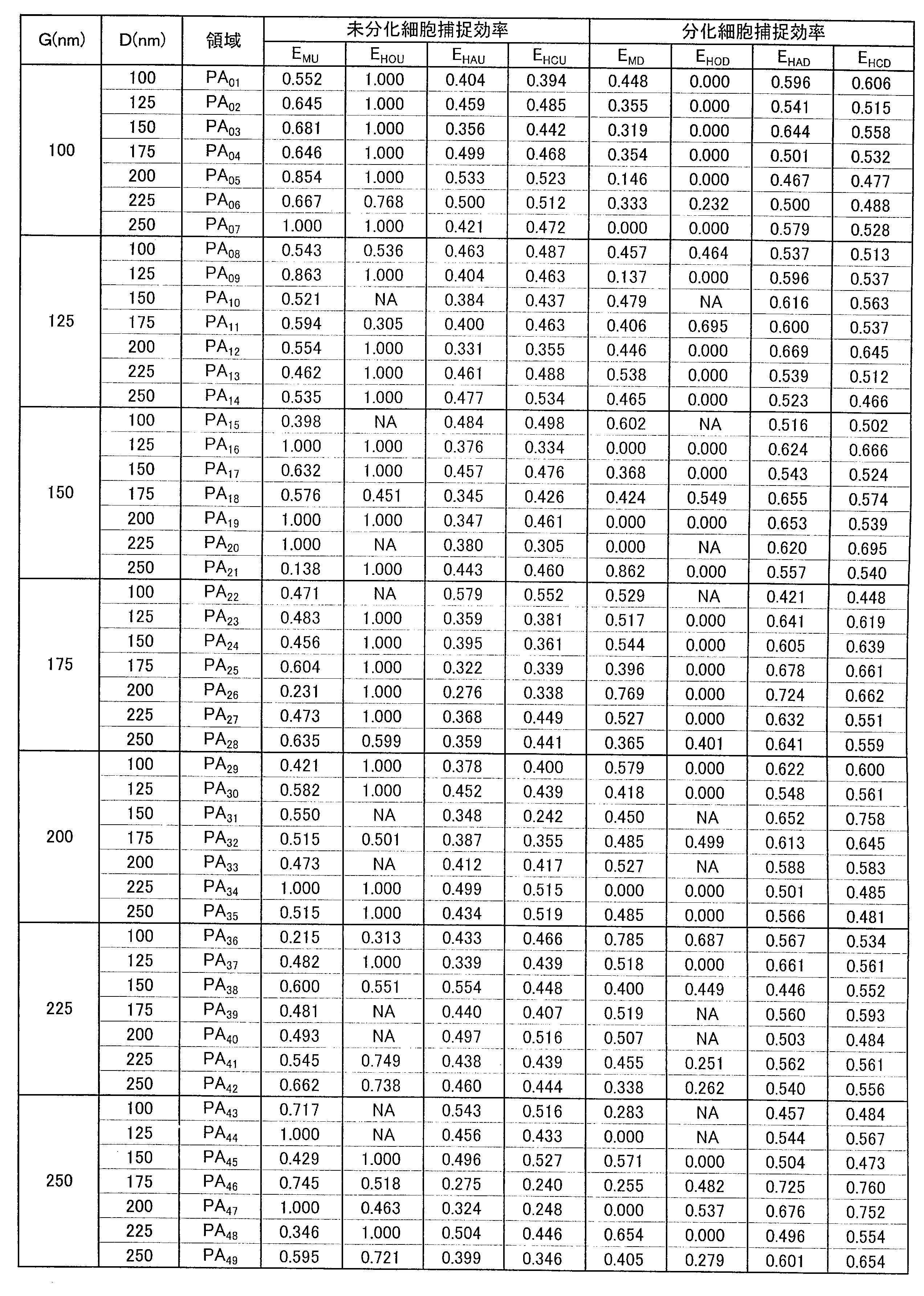
EHCU=PHU/(PHU+PHC)
EHCD=PHC/(PHU+PHC)
表3に示す未分化細胞捕捉効率EMUの算出結果及び分化細胞捕捉効率EMDの算出結果から、マウス由来間葉系幹細胞(未分化細胞)と骨芽細胞(分化細胞)とを含む細胞混合物をピラー状パターン3に接触させた場合に推定される、マウス由来間葉系幹細胞の選択的分離可能性についての総合評価Amu及び骨芽細胞の選択的分離可能性AMDについての総合評価を表4に示す。
表3に示す未分化細胞捕捉効率EHOUの算出結果及び分化細胞捕捉効率EHODの算出結果から、ヒト由来間葉系幹細胞(未分化細胞)と骨芽細胞(分化細胞)とを含む細胞混合物をピラー状パターン3に接触させた場合に推定される、ヒト由来間葉系幹細胞の選択的分離可能性についての総合評価AHOU及び骨芽細胞の選択的分離可能性についての総合評価AHODを表4にあわせて示す。
表3に示す未分化細胞捕捉効率EHAUの算出結果及び分化細胞捕捉効率EHADの算出結果から、ヒト由来間葉系幹細胞(未分化細胞)と脂肪前駆細胞(分化細胞)とを含む細胞混合物をピラー状パターン3に接触させた場合に推定される、ヒト由来間葉系幹細胞の選択的分離可能性についての総合評価AHAU及び脂肪前駆細胞の選択的分離可能性についての総合評価AHADを表4にあわせて示す。
表3に示す未分化細胞捕捉効率EHCUの算出結果及び分化細胞捕捉効率EHCDの算出結果から、ヒト由来間葉系幹細胞(未分化細胞)と軟骨細胞(分化細胞)とを含む細胞混合物をピラー状パターン3に接触させた場合に推定される、ヒト由来間葉系幹細胞の選択的分離可能性についての総合評価AHCU及び軟骨細胞の選択的分離可能性についての総合評価AHCDを表4にあわせて示す。

表4において、総合評価の「◎」、「○」、「△」及び「×」は、下記指標に基づくものである。
◎:EMU,EHOU,EHAU,EHCU>0.8;EMD,EHOD,EHAD,EHCD>0.8
○:0.6<EMU,EHOU,EHAU,EHCU≦0.8;0.6<EMD,EHOD,EHAD,EHCD≦0.8
△:0.5<EMU,EHOU,EHAU,EHCU≦0.6;0.5<EMD,EHOD,EHAD,EHCD≦0.6
×:EMU,EHOU,EHAU,EHCU≦0.5;EMD,EHOD,EHAD,EHCD≦0.5
◎:EMU,EHOU,EHAU,EHCU>0.8;EMD,EHOD,EHAD,EHCD>0.8
○:0.6<EMU,EHOU,EHAU,EHCU≦0.8;0.6<EMD,EHOD,EHAD,EHCD≦0.8
△:0.5<EMU,EHOU,EHAU,EHCU≦0.6;0.5<EMD,EHOD,EHAD,EHCD≦0.6
×:EMU,EHOU,EHAU,EHCU≦0.5;EMD,EHOD,EHAD,EHCD≦0.5
表2~4に示す結果、並びに図6~11から、ナノ凹凸構造体、特に間隔G及び寸法Dが、いずれも100~250nmの範囲内であるピラー状パターン3であれば、細胞の接着性を変化させ得る傾向が見出された。さらに、その接着性の変化は、細胞の分化状態によって異なることが明らかとなった。間葉系幹細胞の捕捉効率EMD,EHODが相対的に高いピラー状パターン3を有する領域(表4に示す総合評価が「◎」又は「○」の領域)においては、間葉系幹細胞とそれから分化誘導させた骨芽細胞とを含む細胞混合物中の間葉系幹細胞がピラー状パターン3に相対的に接着し易くなるため、当該細胞混合物を当該ピラー状パターン3に接触させるだけで、当該細胞混合物から間葉系幹細胞を選択的に、かつ容易に分離・取得することができる、又は間葉系幹細胞の細胞密度を高めることができると考えられる。一方、間葉系幹細胞から分化誘導させた分化細胞(骨芽細胞、脂肪前駆細胞、軟骨細胞等)の捕捉効率EMD,EHOD,EHAD,EHCDが相対的に高いピラー状パターン3を有する領域(表4に示す総合評価が「◎」又は「○」の領域)においては、間葉系幹細胞とそれから分化した分化細胞とを含む細胞混合物中の分化細胞がピラー状パターン3に相対的に接着し易くなるため、当該細胞混合物を当該ピラー状パターン3に接触させるだけで、当該細胞混合物から間葉系幹細胞を選択的に、かつ容易に分離・取得することができる、又は間葉系幹細胞の細胞密度を高めることができると考えられる。
上記試験例の結果から明らかなように、寸法D(D=100~250nm)の複数のピラー状パターン3を間隔G(G=100~250nm)で規則性を有して配列されたナノ凹凸構造体を用いると、未分化細胞及び分化細胞を含む細胞混合物と、ピラー状パターン3とを接触させるだけで、細胞の接着性の違いに基づき、当該細胞混合物から、未分化細胞を選択的に、かつ容易に分離し、取得することができると考えられる。
好ましくは下記(1-1)~(1-7)に示す関係を具備する間隔G及び寸法Dを有するピラー状パターン3が形成された未分化細胞分離用基板1を用いることで、細胞の接着性の違いに基づき、細胞混合物から未分化細胞を選択的に、かつ容易に分離・取得する、又は未分化細胞の細胞密度を高めることができる。
100nm≦G<112.5nm;100nm≦D≦250nm …(1-1)
112.5nm≦G<137.5nm;112.5nm≦D≦250nm …(1-2)
137.5nm≦G<162.5nm;100nm≦D≦250nm …(1-3)
162.5nm≦G<187.5nm;112.5nm≦D≦250nm …(1-4)
187.5nm≦G<212.5nm;100nm≦D<187.5nm又は212.5nm≦D≦250nm …(1-5)
212.5nm≦G<237.5nm;100nm≦D<137.5nm又は212.5nm≦D≦250nm …(1-6)
237.5nm≦G≦250nm;100nm≦D≦250nm …(1-7)
112.5nm≦G<137.5nm;112.5nm≦D≦250nm …(1-2)
137.5nm≦G<162.5nm;100nm≦D≦250nm …(1-3)
162.5nm≦G<187.5nm;112.5nm≦D≦250nm …(1-4)
187.5nm≦G<212.5nm;100nm≦D<187.5nm又は212.5nm≦D≦250nm …(1-5)
212.5nm≦G<237.5nm;100nm≦D<137.5nm又は212.5nm≦D≦250nm …(1-6)
237.5nm≦G≦250nm;100nm≦D≦250nm …(1-7)
特に好ましくは下記(2-1)~(2-7)に示す関係を具備する間隔G及び寸法Dを有するピラー状パターン3が形成された未分化細胞分離用基板1を用いることで、細胞の種類に依存することなく、細胞の接着性の違いに基づき、細胞混合物から未分化細胞を選択的に、かつ容易に分離・取得する、又は未分化細胞の細胞密度を高めることができる。
100nm≦G<112.5nm;112.5nm≦D≦250nm …(2-1)
112.5nm≦G<137.5nm;112.5nm≦D<137.5nm …(2-2)
137.5nm≦G<162.5nm;112.5nm≦D<162.5nm又は187.5nm≦D<237.5nm …(2-3)
162.5nm≦G<187.5nm;162.5nm≦D<212.5nm又は237.5nm≦D≦250nm …(2-4)
187.5nm≦G<212.5nm;212.5nm≦D<237.5nm …(2-5)
212.5nm≦G<237.5nm;237.5nm≦D≦250nm …(2-6)
237.5nm≦G≦250nm;162.5nm≦D<237.5nm …(2-7)
112.5nm≦G<137.5nm;112.5nm≦D<137.5nm …(2-2)
137.5nm≦G<162.5nm;112.5nm≦D<162.5nm又は187.5nm≦D<237.5nm …(2-3)
162.5nm≦G<187.5nm;162.5nm≦D<212.5nm又は237.5nm≦D≦250nm …(2-4)
187.5nm≦G<212.5nm;212.5nm≦D<237.5nm …(2-5)
212.5nm≦G<237.5nm;237.5nm≦D≦250nm …(2-6)
237.5nm≦G≦250nm;162.5nm≦D<237.5nm …(2-7)
細胞混合物に含まれる未分化細胞がマウス由来間葉系幹細胞であって、分化細胞がそれから分化誘導させた骨芽細胞である場合、好ましくは下記(3-1)~(3-7)に示す関係を具備する間隔G及び寸法Dを有するピラー状パターン3が形成された未分化細胞分離用基板1を用いることで、細胞の接着性の違いに基づき、細胞混合物から未分化細胞を選択的に、かつ容易に分離・取得する、又は未分化細胞の細胞密度を高めることができる。
100nm≦G<112.5nm;112.5nm≦D≦250nm …(3-1)
112.5nm≦G<137.5nm;112.5nm≦D<137.5nm …(3-2)
137.5nm≦G<162.5nm;100nm≦D<162.5nm又は187.5nm≦D≦250nm …(3-3)
162.5nm≦G<187.5nm;162.5nm≦D<212.5nm又は237.5nm≦D≦250nm …(3-4)
187.5nm≦G<212.5nm;212.5nm≦D<237.5nm …(3-5)
212.5nm≦G<237.5nm;100nm≦D<112.5nm又は237.5nm≦D≦250nm …(3-6)
237.5nm≦G≦250nm;100nm≦D<137.5nm又は162.5nm≦D<237.5nm …(3-7)
112.5nm≦G<137.5nm;112.5nm≦D<137.5nm …(3-2)
137.5nm≦G<162.5nm;100nm≦D<162.5nm又は187.5nm≦D≦250nm …(3-3)
162.5nm≦G<187.5nm;162.5nm≦D<212.5nm又は237.5nm≦D≦250nm …(3-4)
187.5nm≦G<212.5nm;212.5nm≦D<237.5nm …(3-5)
212.5nm≦G<237.5nm;100nm≦D<112.5nm又は237.5nm≦D≦250nm …(3-6)
237.5nm≦G≦250nm;100nm≦D<137.5nm又は162.5nm≦D<237.5nm …(3-7)
細胞混合物に含まれる未分化細胞がヒト由来間葉系幹細胞であって、分化細胞がそれから分化誘導させた骨芽細胞、脂肪前駆細胞又は軟骨細胞である場合、好ましくは下記(4-1)~(4-7)に示す関係を具備する間隔G及び寸法Dを有するピラー状パターン3が形成された未分化細胞分離用基板1を用いることで、細胞の接着性の違いに基づき、細胞混合物から未分化細胞を選択的に、かつ容易に分離・取得する、又は未分化細胞の細胞密度を高めることができる。
100nm≦G<112.5nm;100nm≦D≦250nm …(4-1)
112.5nm≦G<137.5nm;112.5nm≦D≦250nm …(4-2)
137.5nm≦G<162.5nm;112.5nm≦D≦250nm …(4-3)
162.5nm≦G<187.5nm;112.5nm≦D≦250nm …(4-4)
187.5nm≦G<212.5nm;100nm≦D<187.5nm又は212.5nm≦D≦250nm …(4-5)
212.5nm≦G<237.5nm;100nm≦D<137.5nm又は212.5nm≦D≦250nm …(4-6)
237.5nm≦G≦250nm;137.5nm≦D≦250nm …(4-7)
112.5nm≦G<137.5nm;112.5nm≦D≦250nm …(4-2)
137.5nm≦G<162.5nm;112.5nm≦D≦250nm …(4-3)
162.5nm≦G<187.5nm;112.5nm≦D≦250nm …(4-4)
187.5nm≦G<212.5nm;100nm≦D<187.5nm又は212.5nm≦D≦250nm …(4-5)
212.5nm≦G<237.5nm;100nm≦D<137.5nm又は212.5nm≦D≦250nm …(4-6)
237.5nm≦G≦250nm;137.5nm≦D≦250nm …(4-7)
特に好ましくは下記(5-1)~(5-4)に示す関係を具備する間隔G及び寸法Dを有するピラー状パターン3が形成された未分化細胞分離用基板1を用いることで、細胞混合物に含まれる未分化細胞がヒト由来間葉系幹細胞であって、分化細胞がそれから分化誘導させた骨芽細胞、脂肪前駆細胞及び軟骨細胞のいずれの場合であっても、細胞の接着性の違いに基づき、細胞混合物から未分化細胞を選択的に、かつ容易に分離・取得する、又は未分化細胞の細胞密度を高めることができる。
112.5nm≦G<137.5nm;187.5nm≦D<212.5nm …(5-1)
137.5nm≦G<162.5nm;112.5nm≦D<137.5nm …(5-2)
162.5nm≦G<187.5nm;112.5nm≦D<212.5nm …(5-3)
237.5nm≦G≦250nm;237.5nm≦D≦250nm …(5-4)
137.5nm≦G<162.5nm;112.5nm≦D<137.5nm …(5-2)
162.5nm≦G<187.5nm;112.5nm≦D<212.5nm …(5-3)
237.5nm≦G≦250nm;237.5nm≦D≦250nm …(5-4)
以上のように、当該未分化細胞分離用基板1のピラー状パターン3と、未分化細胞及び分化細胞を含む細胞混合物とを接触させるだけで、当該細胞混合物から未分化細胞を選択的に、かつ容易に分離・取得する、又は未分化細胞の細胞密度を高めることができる。
本発明は、未分化細胞や分化細胞を用いた再生医療に関する技術分野等において有用である。
1…未分化細胞分離用基板
2…基部(基材)
21…主面(第1面)
3…ピラー状パターン
2…基部(基材)
21…主面(第1面)
3…ピラー状パターン
Claims (24)
- 未分化細胞と分化細胞とを含む細胞混合物から前記未分化細胞を分離する方法であって、
複数のピラー状パターンが規則性を有して配列されてなるナノ凹凸構造体を用い、前記複数のピラー状パターンに前記細胞混合物を接触させる工程を含み、
前記ピラー状パターンの間隔Gと寸法Dとが、前記未分化細胞及び前記分化細胞のうちのいずれか一方が前記ピラー状パターンに接着し易く、他方が前記ピラー状パターンに接着し難い関係を有することを特徴とする未分化細胞の分離方法。 - 前記ピラー状パターンの間隔Gと寸法Dとが、いずれも50~500nmの範囲内であることを特徴とする請求項1に記載の未分化細胞の分離方法。
- 前記ピラー状パターンの間隔Gと寸法Dとが、いずれも100~250nmの範囲内であることを特徴とする請求項1又は2に記載の未分化細胞の分離方法。
- 前記ピラー状パターンの間隔Gと寸法Dとが、下記(1-1)~(1-7)のいずれかの関係を有することを特徴とする請求項1~3のいずれかに記載の未分化細胞の分離方法。
100nm≦G<112.5nm;100nm≦D≦250nm …(1-1)
112.5nm≦G<137.5nm;112.5nm≦D≦250nm …(1-2)
137.5nm≦G<162.5nm;100nm≦D≦250nm …(1-3)
162.5nm≦G<187.5nm;112.5nm≦D≦250nm …(1-4)
187.5nm≦G<212.5nm;100nm≦D<187.5nm又は212.5nm≦D≦250nm …(1-5)
212.5nm≦G<237.5nm;100nm≦D<137.5nm又は212.5nm≦D≦250nm …(1-6)
237.5nm≦G≦250nm;100nm≦D≦250nm …(1-7) - 前記ピラー状パターンの間隔Gと寸法Dとが、下記(2-1)~(2-7)のいずれかの関係を有することを特徴とする請求項1~3のいずれかに記載の未分化細胞の分離方法。
100nm≦G<112.5nm;112.5nm≦D≦250nm …(2-1)
112.5nm≦G<137.5nm;112.5nm≦D<137.5nm …(2-2)
137.5nm≦G<162.5nm;112.5nm≦D<162.5nm又は187.5nm≦D<237.5nm …(2-3)
162.5nm≦G<187.5nm;162.5nm≦D<212.5nm又は237.5nm≦D≦250nm …(2-4)
187.5nm≦G<212.5nm;212.5nm≦D<237.5nm …(2-5)
212.5nm≦G<237.5nm;237.5nm≦D≦250nm …(2-6)
237.5nm≦G≦250nm;162.5nm≦D<237.5nm …(2-7) - 前記ピラー状パターンの間隔Gと寸法Dとが、下記(3-1)~(3-7)のいずれかの関係を有することを特徴とする請求項1~3のいずれかに記載の未分化細胞の分離方法。
100nm≦G<112.5nm;112.5nm≦D≦250nm …(3-1)
112.5nm≦G<137.5nm;112.5nm≦D<137.5nm …(3-2)
137.5nm≦G<162.5nm;100nm≦D<162.5nm又は187.5nm≦D≦250nm …(3-3)
162.5nm≦G<187.5nm;162.5nm≦D<212.5nm又は237.5nm≦D≦250nm …(3-4)
187.5nm≦G<212.5nm;212.5nm≦D<237.5nm …(3-5)
212.5nm≦G<237.5nm;100nm≦D<112.5nm又は237.5nm≦D≦250nm …(3-6)
237.5nm≦G≦250nm;100nm≦D<137.5nm又は162.5nm≦D<237.5nm …(3-7) - 前記ピラー状パターンの間隔Gと寸法Dとが、下記(4-1)~(4-7)のいずれかの関係を有することを特徴とする請求項1~3のいずれかに記載の未分化細胞の分離方法。
100nm≦G<112.5nm;100nm≦D≦250nm …(4-1)
112.5nm≦G<137.5nm;112.5nm≦D≦250nm …(4-2)
137.5nm≦G<162.5nm;112.5nm≦D≦250nm …(4-3)
162.5nm≦G<187.5nm;112.5nm≦D≦250nm …(4-4)
187.5nm≦G<212.5nm;100nm≦D<187.5nm又は212.5nm≦D≦250nm …(4-5)
212.5nm≦G<237.5nm;100nm≦D<137.5nm又は212.5nm≦D≦250nm …(4-6)
237.5nm≦G≦250nm;137.5nm≦D≦250nm …(4-7) - 前記ピラー状パターンの間隔Gと寸法Dとが、下記(5-1)~(5-4)のいずれかの関係を有することを特徴とする請求項1~3のいずれかに記載の未分化細胞の分離方法。
112.5nm≦G<137.5nm;187.5nm≦D<212.5nm …(5-1)
137.5nm≦G<162.5nm;112.5nm≦D<137.5nm …(5-2)
162.5nm≦G<187.5nm;112.5nm≦D<212.5nm …(5-3)
237.5nm≦G≦250nm;237.5nm≦D≦250nm …(5-4) - 前記未分化細胞が、マウスに由来する間葉系幹細胞であり、
前記分化細胞が、前記未分化細胞から分化した骨芽細胞であることを特徴とする請求項1~6のいずれかに記載の未分化細胞の分離方法。 - 前記未分化細胞が、ヒトに由来する間葉系幹細胞であることを特徴とする請求項1~5、並びに請求項7及び請求項8のいずれかに記載の未分化細胞の分離方法。
- 前記凹凸構造体は、前記複数のピラー状パターンが正三角形格子の各格子点上に配列されてなることを特徴とする請求項1~10のいずれかに記載の未分化細胞の分離方法。
- 前記凹凸構造体は、前記複数のピラー状パターンが方形格子の各格子点上に配列されてなることを特徴とする請求項1~10のいずれかに記載の未分化細胞の分離方法。
- 未分化細胞と分化細胞とを含む細胞混合物から前記未分化細胞を分離するために用いられる未分化細胞分離用基板であって、
第1面及び前記第1面に対向する第2面を有する基材と、
前記基材の前記第1面に規則性を有して配列形成されてなる複数のピラー状ナノパターンと
を備え、
前記ピラー状ナノパターンの間隔Gと寸法Dとが、前記未分化細胞及び前記分化細胞のうちのいずれか一方が前記ピラー状ナノパターンに接着し易く、他方が前記ピラー状ナノパターンに接着し難い関係を有することを特徴とする未分化細胞分離用基板。 - 前記ピラー状ナノパターンの間隔Gと寸法Dとが、いずれも50~500nmの範囲内であることを特徴とする請求項13に記載の未分化細胞分離用基板。
- 前記ピラー状ナノパターンの間隔Gと寸法Dとが、いずれも100~250nmの範囲内であることを特徴とする請求項13又は14に記載の未分化細胞分離用基板。
- 前記ピラー状パターンの間隔Gと寸法Dとが、下記(1-1)~(1-7)のいずれかの関係を有することを特徴とする請求項13~15のいずれかに記載の未分化細胞分離用基板。
100nm≦G<112.5nm;100nm≦D≦250nm …(1-1)
112.5nm≦G<137.5nm;112.5nm≦D≦250nm …(1-2)
137.5nm≦G<162.5nm;100nm≦D≦250nm …(1-3)
162.5nm≦G<187.5nm;112.5nm≦D≦250nm …(1-4)
187.5nm≦G<212.5nm;100nm≦D<187.5nm又は212.5nm≦D≦250nm …(1-5)
212.5nm≦G<237.5nm;100nm≦D<137.5nm又は212.5nm≦D≦250nm …(1-6)
237.5nm≦G≦250nm;100nm≦D≦250nm …(1-7) - 前記ピラー状パターンの間隔Gと寸法Dとが、下記(2-1)~(2-7)のいずれかの関係を有することを特徴とする請求項13~15のいずれかに記載の未分化細胞分離用基板。
100nm≦G<112.5nm;112.5nm≦D≦250nm …(2-1)
112.5nm≦G<137.5nm;112.5nm≦D<137.5nm …(2-2)
137.5nm≦G<162.5nm;112.5nm≦D<162.5nm又は187.5nm≦D<237.5nm …(2-3)
162.5nm≦G<187.5nm;162.5nm≦D<212.5nm又は237.5nm≦D≦250nm …(2-4)
187.5nm≦G<212.5nm;212.5nm≦D<237.5nm …(2-5)
212.5nm≦G<237.5nm;237.5nm≦D≦250nm …(2-6)
237.5nm≦G≦250nm;162.5nm≦D<237.5nm …(2-7) - 前記ピラー状パターンの間隔Gと寸法Dとが、下記(3-1)~(3-7)のいずれかの関係を有することを特徴とする請求項13~15のいずれかに記載の未分化細胞分離用基板。
100nm≦G<112.5nm;112.5nm≦D≦250nm …(3-1)
112.5nm≦G<137.5nm;112.5nm≦D<137.5nm …(3-2)
137.5nm≦G<162.5nm;100nm≦D<162.5nm又は187.5nm≦D≦250nm …(3-3)
162.5nm≦G<187.5nm;162.5nm≦D<212.5nm又は237.5nm≦D≦250nm …(3-4)
187.5nm≦G<212.5nm;212.5nm≦D<237.5nm …(3-5)
212.5nm≦G<237.5nm;100nm≦D<112.5nm又は237.5nm≦D≦250nm …(3-6)
237.5nm≦G≦250nm;100nm≦D<137.5nm又は162.5nm≦D<237.5nm …(3-7) - 前記ピラー状パターンの間隔Gと寸法Dとが、下記(4-1)~(4-7)のいずれかの関係を有することを特徴とする請求項13~15のいずれかに記載の未分化細胞分離用基板。
100nm≦G<112.5nm;100nm≦D≦250nm …(4-1)
112.5nm≦G<137.5nm;112.5nm≦D≦250nm …(4-2)
137.5nm≦G<162.5nm;112.5nm≦D≦250nm …(4-3)
162.5nm≦G<187.5nm;112.5nm≦D≦250nm …(4-4)
187.5nm≦G<212.5nm;100nm≦D<187.5nm又は212.5nm≦D≦250nm …(4-5)
212.5nm≦G<237.5nm;100nm≦D<137.5nm又は212.5nm≦D≦250nm …(4-6)
237.5nm≦G≦250nm;137.5nm≦D≦250nm …(4-7) - 前記ピラー状パターンの間隔Gと寸法Dとが、下記(5-1)~(5-4)のいずれかの関係を有することを特徴とする請求項13~15のいずれかに記載の未分化細胞分離用基板。
112.5nm≦G<137.5nm;187.5nm≦D<212.5nm …(5-1)
137.5nm≦G<162.5nm;112.5nm≦D<137.5nm …(5-2)
162.5nm≦G<187.5nm;112.5nm≦D<212.5nm …(5-3)
237.5nm≦G≦250nm;237.5nm≦D≦250nm …(5-4) - 前記未分化細胞が、マウスに由来する間葉系幹細胞であり、
前記分化細胞が、前記未分化細胞から分化した骨芽細胞であることを特徴とする請求項13~18のいずれかに記載の未分化細胞分離用基板。 - 前記未分化細胞が、ヒトに由来する間葉系幹細胞であることを特徴とする請求項13~17、並びに請求項19及び20のいずれかに記載の未分化細胞分離用基板。
- 前記複数のピラー状パターンは、正三角形格子の各格子点上に配列されていることを特徴とする請求項13~22のいずれかに記載の未分化細胞分離用基板。
- 前記複数のピラー状パターンは、方形格子の各格子点上に配列されていることを特徴とする請求項13~22のいずれかに記載の未分化細胞分離用基板。
Priority Applications (1)
| Application Number | Priority Date | Filing Date | Title |
|---|---|---|---|
| JP2016566184A JP6695810B2 (ja) | 2014-12-22 | 2015-12-18 | 未分化細胞の分離方法及び未分化細胞分離用基板 |
Applications Claiming Priority (2)
| Application Number | Priority Date | Filing Date | Title |
|---|---|---|---|
| JP2014-258564 | 2014-12-22 | ||
| JP2014258564 | 2014-12-22 |
Publications (1)
| Publication Number | Publication Date |
|---|---|
| WO2016104344A1 true WO2016104344A1 (ja) | 2016-06-30 |
Family
ID=56150364
Family Applications (1)
| Application Number | Title | Priority Date | Filing Date |
|---|---|---|---|
| PCT/JP2015/085443 Ceased WO2016104344A1 (ja) | 2014-12-22 | 2015-12-18 | 未分化細胞の分離方法及び未分化細胞分離用基板 |
Country Status (2)
| Country | Link |
|---|---|
| JP (1) | JP6695810B2 (ja) |
| WO (1) | WO2016104344A1 (ja) |
Cited By (2)
| Publication number | Priority date | Publication date | Assignee | Title |
|---|---|---|---|---|
| JP2019041719A (ja) * | 2017-09-06 | 2019-03-22 | 大日本印刷株式会社 | 細胞培養用構造体、細胞培養容器及び細胞培養用構造体の製造方法 |
| JP2020156443A (ja) * | 2019-03-28 | 2020-10-01 | 東京都公立大学法人 | 細胞培養用基板および間葉系幹細胞の分化制御方法 |
Citations (2)
| Publication number | Priority date | Publication date | Assignee | Title |
|---|---|---|---|---|
| JPH0276570A (ja) * | 1988-09-13 | 1990-03-15 | Dainippon Printing Co Ltd | 細胞培養基板 |
| JP2015142526A (ja) * | 2014-01-31 | 2015-08-06 | 大日本印刷株式会社 | 被分離体の分離方法、及び被分離体分離用基板 |
-
2015
- 2015-12-18 JP JP2016566184A patent/JP6695810B2/ja active Active
- 2015-12-18 WO PCT/JP2015/085443 patent/WO2016104344A1/ja not_active Ceased
Patent Citations (2)
| Publication number | Priority date | Publication date | Assignee | Title |
|---|---|---|---|---|
| JPH0276570A (ja) * | 1988-09-13 | 1990-03-15 | Dainippon Printing Co Ltd | 細胞培養基板 |
| JP2015142526A (ja) * | 2014-01-31 | 2015-08-06 | 大日本印刷株式会社 | 被分離体の分離方法、及び被分離体分離用基板 |
Non-Patent Citations (2)
| Title |
|---|
| HUANG LR ET AL.: "Continuous particle separation through deterministic lateral displacement.", SCIENCE, vol. 304, no. 5673, 14 May 2004 (2004-05-14), pages 987 - 990 * |
| MASUMI YAMADA ET AL.: "Saibo no Bunri · Senbatsu no Tameno Micro Ryutai Device", JOURNAL OF THE SOCIETY FOR BIOSCIENCE AND BIOENGINEERING, vol. 92, no. 4, 25 April 2014 (2014-04-25), pages 153 - 156 * |
Cited By (3)
| Publication number | Priority date | Publication date | Assignee | Title |
|---|---|---|---|---|
| JP2019041719A (ja) * | 2017-09-06 | 2019-03-22 | 大日本印刷株式会社 | 細胞培養用構造体、細胞培養容器及び細胞培養用構造体の製造方法 |
| JP2020156443A (ja) * | 2019-03-28 | 2020-10-01 | 東京都公立大学法人 | 細胞培養用基板および間葉系幹細胞の分化制御方法 |
| JP7320827B2 (ja) | 2019-03-28 | 2023-08-04 | 東京都公立大学法人 | 細胞培養用基板および間葉系幹細胞の分化制御方法 |
Also Published As
| Publication number | Publication date |
|---|---|
| JPWO2016104344A1 (ja) | 2017-11-30 |
| JP6695810B2 (ja) | 2020-05-20 |
Similar Documents
| Publication | Publication Date | Title |
|---|---|---|
| JP7390751B2 (ja) | 細胞培養基材、がん細胞集合体及び該基材を用いたその製造方法、並びに該がん細胞集合体を用いた薬剤のスクリーニング方法 | |
| JP5497011B2 (ja) | 哺乳類の幹細胞の成長および分化のための生体適合性材料 | |
| EP1874367B1 (en) | Biocompatible material for surgical implants and cell guiding tissue culture surfaces | |
| Girard et al. | Isolating nasal olfactory stem cells from rodents or humans | |
| JP2020036621A (ja) | 細胞培養支持体、細胞培養装置、細胞培養キット、及び細胞シート | |
| WO2016104344A1 (ja) | 未分化細胞の分離方法及び未分化細胞分離用基板 | |
| JPWO2020090860A1 (ja) | miRNAの抽出方法、および、miRNAの解析方法 | |
| WO2020090859A1 (ja) | 細胞外小胞を捕捉するために用いられるデバイス、細胞外小胞の保存方法および移送方法 | |
| Bérces et al. | Effect of nanostructures on anchoring stem cell-derived neural tissue to artificial surfaces | |
| JP2017205021A (ja) | 初代癌細胞のスフェロイド作製方法、スフェロイド、スクリーニング方法、及び、診断方法 | |
| JPWO2011052281A1 (ja) | 神経スフェロイドネットワークの構築方法 | |
| Chen et al. | Regulation of stem cell functions by micro-patterned structures | |
| JP7813435B2 (ja) | 細胞塊形成部材、培養容器、培養細胞の生産方法、細胞塊形成部材付き培養細胞 | |
| JP2014138605A (ja) | 哺乳類の幹細胞の成長および分化のための生体適合性材料 | |
| JP2019041719A (ja) | 細胞培養用構造体、細胞培養容器及び細胞培養用構造体の製造方法 | |
| JP7053065B1 (ja) | 細胞シート製造用細胞培養器材、回収用支持体、及び細胞シート製造用キット | |
| JP6597118B2 (ja) | 細胞挙動評価用基板、細胞挙動評価用容器及び細胞挙動評価方法 | |
| TWI920175B (zh) | 細胞層片製造用細胞培養器材、細胞層片製造用套組及細胞層片製造方法 | |
| JP7802784B2 (ja) | 組織工学におけるフラクタル | |
| Sgro et al. | A high-throughput method for generating uniform microislands for autaptic neuronal cultures | |
| JP2010068766A (ja) | 三次元細胞構造体の作製方法 | |
| Liu et al. | Schwann Cells Migration on Patterned PDMS Microgrooved Surface | |
| GR1009056B (el) | Νανοδομημενα με ηλεκτρικες εκκενωσεις πλασματος υποστρωματα για επιλεκτικο εμπλουτισμο καρκινικων κυτταρων | |
| Özçelik | Interaction between micro and nano patterned polymeric surfaces and different cell types | |
| WO2020204106A1 (ja) | 三次元培養皮膚シート、その製造に使用するための細胞培養容器及びその製造方法 |
Legal Events
| Date | Code | Title | Description |
|---|---|---|---|
| 121 | Ep: the epo has been informed by wipo that ep was designated in this application |
Ref document number: 15872913 Country of ref document: EP Kind code of ref document: A1 |
|
| ENP | Entry into the national phase |
Ref document number: 2016566184 Country of ref document: JP Kind code of ref document: A |
|
| NENP | Non-entry into the national phase |
Ref country code: DE |
|
| 122 | Ep: pct application non-entry in european phase |
Ref document number: 15872913 Country of ref document: EP Kind code of ref document: A1 |