WO2016104176A1 - ガスセンサ - Google Patents
ガスセンサ Download PDFInfo
- Publication number
- WO2016104176A1 WO2016104176A1 PCT/JP2015/084755 JP2015084755W WO2016104176A1 WO 2016104176 A1 WO2016104176 A1 WO 2016104176A1 JP 2015084755 W JP2015084755 W JP 2015084755W WO 2016104176 A1 WO2016104176 A1 WO 2016104176A1
- Authority
- WO
- WIPO (PCT)
- Prior art keywords
- atmosphere
- gas
- insulator
- side insulator
- shoulder
- Prior art date
Links
Images


Classifications
-
- G—PHYSICS
- G01—MEASURING; TESTING
- G01N—INVESTIGATING OR ANALYSING MATERIALS BY DETERMINING THEIR CHEMICAL OR PHYSICAL PROPERTIES
- G01N27/00—Investigating or analysing materials by the use of electric, electrochemical, or magnetic means
- G01N27/26—Investigating or analysing materials by the use of electric, electrochemical, or magnetic means by investigating electrochemical variables; by using electrolysis or electrophoresis
- G01N27/403—Cells and electrode assemblies
- G01N27/406—Cells and probes with solid electrolytes
- G01N27/407—Cells and probes with solid electrolytes for investigating or analysing gases
- G01N27/4078—Means for sealing the sensor element in a housing
-
- G—PHYSICS
- G01—MEASURING; TESTING
- G01N—INVESTIGATING OR ANALYSING MATERIALS BY DETERMINING THEIR CHEMICAL OR PHYSICAL PROPERTIES
- G01N27/00—Investigating or analysing materials by the use of electric, electrochemical, or magnetic means
- G01N27/26—Investigating or analysing materials by the use of electric, electrochemical, or magnetic means by investigating electrochemical variables; by using electrolysis or electrophoresis
- G01N27/403—Cells and electrode assemblies
- G01N27/406—Cells and probes with solid electrolytes
- G01N27/407—Cells and probes with solid electrolytes for investigating or analysing gases
- G01N27/409—Oxygen concentration cells
Definitions
- the present invention relates to a gas sensor.
- a gas sensor that is installed in an exhaust system of an internal combustion engine such as an automobile engine and detects a specific gas such as an oxygen concentration in exhaust gas (a gas to be measured) is known.
- a gas sensor disclosed in Japanese Patent Application Laid-Open No. 2007-199005 includes a sensor element that detects the concentration of a predetermined gas component in a gas to be measured, an element-side insulator that is inserted and held inside the sensor element, An air-side insulator that covers the base end side and forms an air atmosphere inside, a housing that inserts and holds both insulators, and an air-side cover that is fixed to the base end side of the housing.
- the atmosphere side cover has a large diameter portion on the distal end side, a small diameter portion on the proximal end side, and a shoulder portion between the large diameter portion and the small diameter portion.
- the shoulder portion presses the proximal end surface of the atmosphere-side insulator toward the distal end side via the biasing member, thereby bringing the atmosphere-side insulator into contact with the element-side insulator.
- a seal in which a sealing material such as talc is compressed is formed between the housing and the element side insulator, and an atmospheric atmosphere formed inside the atmosphere side insulator as a reference gas and a gas to be measured The gas atmosphere to be measured is isolated from each other.
- the gas sensor Since the gas sensor is provided in an internal combustion engine, deformation or the like may occur when the compressed sealing material is exposed to a high temperature and high pressure environment for a long period of time. When such deformation occurs, a gap is generated between the sealing material and the element-side insulator, and the gas to be measured flows into the atmosphere-side cover. Further, the atmospheric atmosphere formed inside the atmosphere-side insulator The oxygen gas concentration in the atmospheric atmosphere as the reference gas may fluctuate. As a result, it becomes difficult to obtain an accurate sensor output. In view of this, various proposals have been made regarding the selection of the material of the sealing material and the compression method in order to reduce deformation of the sealing material due to high temperature and high pressure. However, in any case, deformation of the sealing material cannot be completely prevented, so there is room for improvement in order to obtain an accurate sensor output.
- the air side insulator is pressed against the element side insulator to bring them into close contact, and the gas leaked from the seal does not flow into the atmosphere inside the atmosphere side insulator from between the two.
- it can be considered to selectively flow through the space outside the atmosphere-side insulator.
- the leaked gas is accumulated in the space. If the leaked gas continues to be accumulated in the space, there is a problem that any of the leaked gas flows into the atmosphere inside the atmosphere side insulator from between the atmosphere side insulator and the element side insulator.
- the present invention has been made in view of the above background, and it is possible to obtain an accurate sensor output by preventing the gas to be measured from flowing into the atmosphere inside the atmosphere-side insulator, and to damage the atmosphere-side insulator.
- An object of the present invention is to provide a gas sensor that can reduce the manufacturing cost while preventing the above.
- One aspect of the present invention covers a sensor element that detects a concentration of a predetermined gas component in a gas to be measured, an element-side insulator that inserts and holds the sensor element inside, and a base end side of the sensor element.
- An air side insulator that forms an air atmosphere inside, a housing that inserts and holds the element side insulator and the air side insulator inside, an inner peripheral surface of the housing, and an outer peripheral surface of the element side insulator
- a gas sensor having a seal filled with a sealant in between and an atmosphere-side cover fixed to the base end side of the housing,
- the atmosphere-side cover includes a large-diameter portion formed on a distal end side, a small-diameter portion formed on a proximal end side than the large-diameter portion and having a diameter smaller than the diameter of the large-diameter portion, and the small-diameter portion And a shoulder that presses the proximal end surface of the atmosphere-side insul
- a vent hole formed in the base end, Between the outer peripheral surface of the atmosphere-side insulator and the inner peripheral surface of the large-diameter portion, an outer space portion adjacent to the seal is formed, Inside the small diameter portion, an external path communicating with the vent hole is formed, The shoulder portion is formed with an abutting portion that abuts on the urging member and a separation portion that is separated from the urging member, and the outer portion is disposed between the separation portion and the urging member.
- the gas sensor is characterized in that a communication path is formed to communicate the space portion and the external path.
- the gas to be measured leaked from the seal reaches the outer space formed adjacent to the seal. Then, through the communication path formed in the shoulder portion, the air flows through the external path and is discharged from the vent hole to the outside of the atmosphere side cover. Further, since the shoulder portion of the atmosphere side cover presses the atmosphere side insulator toward the element side insulator via the biasing member, both are brought into close contact with each other to ensure airtightness between the two. As a result, the measured gas is prevented from flowing into the atmospheric atmosphere as the reference gas formed in the atmospheric cover, and a more accurate sensor output can be obtained.
- separation part and contact part which form a communicating path are formed in the shoulder part of an atmosphere side cover, compared with the case where an uneven
- the separation portion and the contact portion provided on the shoulder portion of the atmosphere side cover can be easily formed by a press or the like, an uneven portion is formed on the base end surface of the atmosphere side insulator so that the atmosphere side cover The manufacturing cost can be reduced as compared with the case where the flow path is formed between the shoulder portion.
- the communication path is formed in the shoulder of the atmosphere side cover. Therefore, the communication path is easier to dissipate heat because it is formed at a position closer to the outside air than the case where an uneven portion is formed on the atmosphere-side insulator and the flow path is formed between the communication path and the shoulder.
- the temperature is low.
- the gas to be measured leaked from the seal actively circulates in the communication path having a lower temperature than the inside of the atmospheric insulator having a high temperature. Therefore, the gas to be measured leaked from the seal is effectively suppressed from flowing into the atmosphere inside the atmosphere-side insulator, and a more accurate sensor output can be obtained.
- the present invention it is possible to obtain an accurate sensor output by preventing the gas to be measured from flowing into the atmosphere inside the atmosphere side insulator, and to prevent the atmosphere side insulator from being damaged.
- a gas sensor that can reduce the manufacturing cost can be provided.
- FIG. 3 is a cross-sectional view of the gas sensor in the first embodiment.
- the III-III sectional view taken on the line of the atmosphere side cover in FIG. 3 is a perspective view of an urging member in Embodiment 1.
- FIG. FIG. 6 is an enlarged cross-sectional view of the periphery of a shoulder in a second modification example of the first embodiment.
- FIG. 6 is a top view of an urging member in Embodiment 2.
- FIG. 10 is a top view of an urging member in a first modification example of Embodiment 2.
- FIG. 10 is a top view of an urging member in a second modification of the second embodiment.
- FIG. 12 is a top view of an urging member in a third modification example of the second embodiment.
- FIG. 9 is a perspective view of an urging member in Embodiment 3.
- FIG. 6 is an enlarged cross-sectional view of the periphery of a shoulder portion of a gas sensor in Example 3. The side view of the urging member and the atmosphere side insulator in Example 4.
- FIG. 6 is a top view of an urging member and an atmospheric side insulator in Example 4.
- FIG. 6 is an enlarged cross-sectional view of the periphery of a shoulder portion of a gas sensor in Example 4.
- FIG. The side view of the biasing member and the air
- the gas sensor can be applied to, for example, an A / F sensor, an O 2 sensor, a NOx sensor, a PM sensor, and the like.
- a side installed in an exhaust pipe of an automobile internal combustion engine or the like is a front end side, and the opposite side is a base end side.
- the longitudinal direction of the sensor element is referred to as the axial direction.
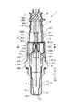
- the gas sensor 1 includes a sensor element 2, an element-side insulator 31, an atmosphere-side insulator 32, a housing 4, a seal 5, and an atmosphere-side cover 6.
- the sensor element 2 detects the concentration of a predetermined gas component in the gas to be measured.
- the element side insulator 31 inserts and holds the sensor element 2 inside.
- the atmosphere-side insulator 32 covers the base end side 21 of the sensor element 2 and forms an atmosphere 30 inside.
- the housing 4 inserts and holds the element side insulator 31 and the atmosphere side insulator 32 inside.
- the seal 5 is formed by filling a seal material 56 between the inner peripheral surface 41 of the housing 4 and the outer peripheral surface 31 b of the element side insulator 31.
- the atmosphere side cover 6 is fixed to the base end side Y ⁇ b> 1 of the housing 4.
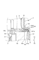
- the atmosphere-side cover 6 includes a large-diameter portion 61 formed on the distal end side Y2 and a small-diameter portion formed on the proximal end side Y1 than the large-diameter portion 61 and having a diameter smaller than the diameter of the large-diameter portion 61.
- 62 and an outer shoulder portion 63 formed between the small diameter portion 62 and the large diameter portion 61 and pressing the proximal end surface 32a of the atmosphere side insulator 32 to the distal end side Y2 via the biasing member (disc spring 7).
- a vent 641 formed in the base end portion 64.
- An outer space 50 adjacent to the seal 5 is formed between the outer peripheral surface 32 b of the atmosphere-side insulator 32 and the inner peripheral surface 61 a of the large-diameter portion 61.
- An external path 51 communicating with the vent hole 641 is formed inside the small diameter portion 62.
- the outer shoulder 63 is formed with an abutting portion 631 that abuts against the urging member (the disc spring 7) and a separation portion (also referred to as a non-abutting portion) 632 that is separated from the urging member (the disc spring 7). ing.
- a communication path 52 that allows the outer space 50 and the external path 51 to communicate is formed between the separation portion 632 and the biasing member (the disc spring 7).
- the gas sensor 1 is attached to the exhaust gas pipe through the housing 4 so that the atmosphere side cover 6 is outside.
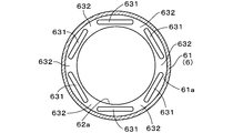
- the atmosphere side cover 6 has a substantially cylindrical shape.
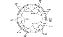
- the outer shoulder 63 is formed in the entire circumferential direction of the atmosphere-side cover 6 at the approximate center in the axial direction Y of the atmosphere-side cover 6. As shown in FIG. 2, a part of the atmosphere-side cover 6 that forms the outer shoulder 63 protrudes toward the distal end Y ⁇ b> 2 in the axial direction Y to form a contact portion 631 that contacts the disc spring 7 as a biasing member. Has been.
- the contact portion 631 has a substantially hemispherical shape, and the apex 631 a on the tip end side Y ⁇ b> 2 of the contact portion 631 is in contact with the disc spring 7.
- twelve contact portions 631 are formed at equal intervals in the circumferential direction of the atmosphere-side cover 6.
- a separation portion 632 that is separated from the disc spring 7 (see FIG. 2) as an urging member is formed between two adjacent contact portions 631. As shown in FIG. 2, the space between the separation portion 632 and the disc spring 7 forms a communication path 52.
- the inner diameter of the large-diameter portion 61 of the atmosphere-side cover 6 is larger than the outer diameter of the atmosphere-side insulator 32, and the inner peripheral surface 61 a of the large-diameter portion 61 and the atmosphere-side insulator 32.
- An outer space 50 is formed between the outer peripheral surface 32b and the outer space 32b. The outer space 50 is adjacent to the seal 5 and communicates with the communication path 52.
- the inner diameter of the small-diameter portion 62 of the atmosphere-side cover 6 is smaller than the inner diameter of the large-diameter portion 61, and the end of the sensor element 2 on the base end side Y ⁇ b> 1 is inside the small-diameter portion 62.
- the lead wire 14 connected to the portion 21 is located, and an external path 51 communicating with the communication path 52 is formed.
- the base end portion 64 of the atmosphere side cover 6 is open, and a vent hole 641 is formed.
- a filter cover 8 is provided on the proximal end side Y ⁇ b> 1 of the atmosphere-side cover 6.
- the filter cover 8 has a substantially cylindrical shape, and the proximal end portion of the atmosphere-side cover 6 is fitted into the distal end side Y2.
- a ventilation portion 66 to which a ventilation filter 65 is attached is formed in the circumferential direction of the ventilation hole 641 of the atmosphere side cover 6 on the side wall of the filter cover 8. Air is introduced into the atmosphere-side cover 6 through the ventilation portion 66. In addition, water or the like is prevented from entering from the ventilation portion 66 by the ventilation filter 65.
- the vent 641 (vent 66) communicates with the external path 51. Therefore, the outer space 50, the communication path 52, the external path 51, and the ventilation part 66 are in communication.
- an element side insulator 31 for holding the sensor element 2 therein and an atmosphere side insulator 32 disposed on the base end side Y1 of the element side insulator 31 are provided.
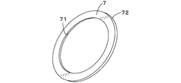
- a disc spring 7 as an urging member is disposed on the base end surface 32 a of the atmosphere-side insulator 32.
- the disc spring 7 is disposed between the contact portion 631 and the atmosphere side insulator 32 in a state of being urged so as to press the atmosphere side insulator 32 toward the element side insulator 31.
- the disc spring 7 is an annular elastic member along the outer shoulder 63, and both the inner peripheral surface 71 and the outer peripheral surface 72 are circular in plan view. .
- the outer diameter of the disc spring 7 is larger than the inner diameter of the small diameter portion 62 in the atmosphere side cover 6 and slightly smaller than the inner diameter of the large diameter portion 61.
- the gas sensor 1 is provided with a measured gas side cover 10 on the front end side Y ⁇ b> 2 of the housing 4.
- the measured gas side cover 10 includes an outer cover 11 and an inner cover 12.
- the outer cover 11 and the inner cover 12 each have a plurality of measured gas inlets 13.
- the measurement gas atmosphere 100 is formed in the measurement gas side cover 10 by introducing the measurement gas from the measurement gas introduction port 13.
- the seal 5 includes a metal ring 54 that is swaged by a swaged portion 42 formed at a proximal end portion of the housing 4, an insulating member 55 that insulates the sensor element 2 and the housing 4, It consists of a powder sealing material 56 made of talc or the like.
- the gas atmosphere 100 to be measured formed on the front end side Y2 of the gas sensor 1 and the air atmosphere 30 formed on the base end side Y1 are hermetically separated by the seal 5.
- the seal 5 may be deformed due to high temperature and high pressure by the internal combustion engine.
- the measurement gas G leaks from the seal 5.
- the gas to be measured G leaked from the seal 5 reaches the outer space 50 as shown in FIG.
- the air flows through the external path 51 and is discharged from the vent 641 (vent 66) to the outside of the atmosphere-side cover 6.
- the outer shoulder 63 of the atmosphere-side cover 6 presses the atmosphere-side insulator 32 toward the element-side insulator 31 via the disc spring 7, both of them are brought into close contact with each other to ensure airtightness between them. ing.
- the measurement gas G is suppressed from flowing into the atmospheric atmosphere 30 as the reference gas formed in the atmospheric side cover 6, and a more accurate sensor output can be obtained.
- the separation part 632 and the contact part 631 which form the communicating path 52 are formed in the outer side shoulder part 63 of the atmosphere side cover 6, when forming an uneven
- the concentration of stress on the base end face 32a of the atmosphere side insulator 32 is relaxed, and the atmosphere side insulator 32 is prevented from being damaged.
- the separation portion 632 and the contact portion 631 provided on the outer shoulder 63 of the atmosphere-side cover 6 can be easily formed by a press machine or the like, an uneven portion is formed on the base end surface 32a of the atmosphere-side insulator 32. Compared to the case where the flow path is formed between the outer shoulder portion 63 of the atmosphere side cover 6 and the manufacturing cost is reduced.
- the communication path 52 is formed in the outer shoulder 63 of the atmosphere side cover 6.
- the communication passage 52 is formed at a position closer to the outside air than in the case where the concave and convex portions are formed on the atmosphere side insulator 32 and the flow path is formed between the outer shoulder portions 63, and therefore, heat radiation is reduced. It is easy and has a relatively low temperature. Then, based on the thermophoresis effect, the measurement gas G leaked from the seal 5 actively circulates in the communication path 52 that is cooler than the inside of the atmosphere-side insulator 32 that is hot. Therefore, the gas G to be measured leaked from the seal 5 is effectively suppressed from flowing into the atmospheric atmosphere 30 inside the atmospheric insulator 32, and a more accurate sensor output can be obtained.
- the contact portion 631 is formed in a shape that protrudes in a substantially hemispherical shape on the distal end side Y2 at the outer shoulder 63, and a separation portion 632 is formed between the adjacent contact portions 631.
- the abutting portion 631 is formed in a rib shape extending in the tangential direction of the inner peripheral surface 62 a of the small diameter portion 62 while projecting to the distal end side Y ⁇ b> 2 at the outer shoulder portion 63.
- a separating portion 632 may be formed between the two matching contact portions 631. Also. As shown in FIGS.
- the abutting portion 631 is formed in a rib shape extending in the radial direction while projecting to the proximal end Y1 in the outer shoulder portion 63, and the separating portion 632 is provided between the adjacent abutting portions 631. May be formed. In either case, the same effect as this example is achieved.
- the gas to be measured is prevented from flowing into the atmosphere 30 inside the atmosphere side insulator 32, thereby obtaining an accurate sensor output and preventing the atmosphere side insulator 32 from being damaged.
- the gas sensor 1 it is possible to provide the gas sensor 1 that can reduce the manufacturing cost while preventing it.
- the gas sensor 1 of this example includes a disc spring 700 shown in FIG. 8 instead of the disc spring 7 (FIG. 3) in the gas sensor 1 of Example 1 as an urging member.
- the disc spring 700 is an annular elastic member along the outer shoulder 63, and a plurality of notches 701 are formed on the inner peripheral surface 71 so as to form a gas escape portion 520 communicating with the communication path 52.
- Four notches 701 are arranged at intervals of 90 °.
- Each notch 701 is formed in a rectangular shape when viewed from the axial direction Y, and the radially outer surface 701a of the notch 701 is located radially outside the outer peripheral surface 32b of the atmosphere-side insulator 32. Yes.
- FIG. 8 As a result, as shown in FIG.
- a gas escape portion 520 communicating with the communication path 52 is formed between the notch 701 and the outer peripheral surface 32 b of the atmosphere side insulator 32 when viewed from the axial direction Y. It is formed.
- Other configurations are the same as those in the first embodiment.
- symbol as the case of Example 1 is attached
- the gas G to be measured leaked from the seal 5 flows from the outer space 50 through the gas passage 520 through the communication passage 52 to the external passage 51, and is ventilated. It will be discharged
- the gas to be measured G leaked from the seal 5 circulates more positively through the communication passage 52, so that the gas to be measured G is introduced into the atmosphere 30 (see FIG. 1) inside the atmosphere side insulator 32. Inflow is effectively suppressed, and a more accurate sensor output can be obtained.
- the same effects as those of the first embodiment are obtained.
- the notch portion 701 is formed on the inner peripheral surface 71 of the disc spring 700 to form the gas escape portion 520.
- a plurality of notch portions are formed on the outer peripheral surface 72 of the disc spring 710 as shown in FIG.
- the gas escape portion 520 can be formed.
- the four notches 711 are arranged at equal intervals every 90 °.
- the gas escape portion 520 can be formed by forming notches 712 and 713 on both the outer peripheral surface 72 and the inner peripheral surface 71 of the disc spring 720.
- both notches 712 and 713 are provided at two locations, and the notches 712 and 713 are connected to each other. Therefore, the disc spring 720 is divided into two parts, and a gas escape portion 520 is formed in the gap between the two.
- the gas escape portion 520 may be formed by forming a through hole 714 in the disc spring 730.
- the gas sensor 1 of this example includes a wave washer 750 shown in FIG. 13 instead of the disc spring 7 (FIG. 3) as the biasing member in the gas sensor 1 of Example 1 as the biasing member.
- the wave washer 750 is an annular elastic member along the outer shoulder 63, and has a proximal end protruding portion 751 that curves to protrude toward the proximal end Y1, and a distal end.
- a leading end side protruding portion 752 that is curved so as to protrude to the side Y2 is formed. As shown in FIG.
- the gas G to be measured leaked from the seal 5 reaches the external path 51 from the outer space part 50 via the gas escape part 521 and the communication path 52, and from the ventilation part 66. Will be discharged. Thereby, as in the case of the second embodiment, a more accurate sensor output can be obtained.
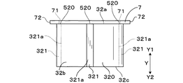
- the gas sensor 1 of this example includes an atmosphere side insulator 320 shown in FIGS. 15 to 17 instead of the atmosphere side insulator 32 (see FIG. 1) in the first embodiment.
- a groove portion 321 extending along the axial direction Y is formed on the outer peripheral surface 32 b of the atmosphere-side insulator 320 so as to communicate with the communication path 52.
- the radially inner side surface 321 a of the groove portion 321 is located on the radially inner side with respect to the inner peripheral surface 71 of the disc spring 7. Accordingly, as shown in FIG.
- a gas escape portion 520 is formed between the inner peripheral surface 71 of the disc spring 7 and the groove portion 321 of the atmosphere side insulator 320 from the axial direction Y.
- Other configurations are the same as those in the first embodiment.
- symbol as the case of Example 1 is attached
- the gas G to be measured leaked from the seal 5 reaches the external path 51 from the outer space part 50 through the gas escape part 520 and the communication path 52, and the ventilation part 66 ( (See FIG. 1).
- the gas to be measured G leaked from the seal 5 is more actively circulated through the communication passage 52, and therefore the gas to be measured G is introduced into the atmosphere 30 (see FIG. 1) inside the atmosphere-side insulator 320. Inflow is effectively suppressed, and a more accurate sensor output can be obtained.
- the same effects as those of the first embodiment are obtained.
- the disc spring 700 may be provided as an urging member similar to the case of the second embodiment.
- the notch portion 701 (see FIG. 8) formed in the disc spring 700 and the groove portion 321 may overlap with each other, or both may not overlap. It is good as well.
- the function and effect obtained by providing the notch portion 701 in the second embodiment are synergistically obtained, so that a more accurate sensor output can be obtained.
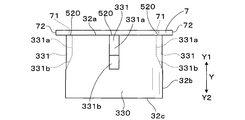
- the outer peripheral groove portion 321 is continuously formed from the end portion on the base end side Y1 to the end portion on the front end side Y2 of the outer peripheral surface 32b of the atmosphere side insulator 320, but instead of this, FIG. As shown in FIG. 3, it is good also as the outer peripheral groove part 331 formed along the axial direction Y continuously from the base end surface 32a of the base end side Y1 to the center part in the axial direction Y among the outer peripheral faces 32b of the atmosphere side insulator 330. .
- the radially inner side surface 331a on the base end side Y1 is a surface parallel to the axial direction Y
- the radially inner side surface 331b on the distal end side Y2 is the distal end side Y2.
- the surface is inclined with respect to the axial direction Y so as to go radially outward as it goes to. Even in this case, the same effects as the present example can be obtained.
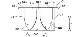
- the outer peripheral surface 32 b of the atmosphere side insulator 340 extends along the axial direction Y and spreads in the circumferential direction toward the distal end side Y ⁇ b> 2.
- An outer peripheral groove 341 may be formed.
- the measurement gas G leaked from the seal 5 (see FIG. 1) is guided to the gas escape portion 520 along the shape of the outer peripheral groove portion 341.
- the gas G to be measured can be positively discharged to the outside through the communication path 52 and the external path 51 (see FIG. 1), so that the gas to be measured is measured in the air atmosphere 30 (see FIG. 1) inside the air side insulator 340. Inflow of the gas G is effectively suppressed, and a more accurate sensor output can be obtained.
Landscapes
- Chemical & Material Sciences (AREA)
- Life Sciences & Earth Sciences (AREA)
- Health & Medical Sciences (AREA)
- Physics & Mathematics (AREA)
- Chemical Kinetics & Catalysis (AREA)
- Electrochemistry (AREA)
- Molecular Biology (AREA)
- Analytical Chemistry (AREA)
- Biochemistry (AREA)
- General Health & Medical Sciences (AREA)
- General Physics & Mathematics (AREA)
- Immunology (AREA)
- Pathology (AREA)
- Measuring Oxygen Concentration In Cells (AREA)
Abstract
ガスセンサは、センサ素子、素子側絶縁碍子、大気側絶縁碍子、ハウジング、ハウジングと素子側絶縁碍子との間に配置されたシール、及び大気側カバーを有する。大気側カバーは、大径部と、小径部と、両者の間に形成されて付勢部材を介して大気側絶縁碍子の基端面を先端側に押圧して大気側絶縁碍子を素子側絶縁碍子に当接させる肩部とを有する。肩部には付勢部材に当接する当接部と付勢部材から離隔する離隔部とが形成され、離隔部と付勢部材との間に外側空間部と外部経路とを連通させる連通路が形成される。これにより、被測定ガスが大気側絶縁碍子の内側の大気雰囲気に流入することが防止され正確なセンサ出力が得られる。また、大気側絶縁碍子の破損が防止され、製造コストを低減することが可能となる。
Description
本発明は、ガスセンサに関する。
自動車エンジン等の内燃機関の排気系に設置され、排気ガス(被測定ガス)における酸素濃度等の特定ガスを検知するガスセンサが知られている。例えば、特開2007-199005号公報に開示のガスセンサは、被測定ガス中の所定のガス成分の濃度を検出するセンサ素子と、センサ素子を内側に挿通保持する素子側絶縁碍子と、センサ素子の基端側を覆って内側に大気雰囲気を形成する大気側絶縁碍子と、両絶縁碍子を挿通保持するハウジングと、ハウジングの基端側に固定される大気側カバーとを有する。大気側カバーは、先端側に大径部を有し、基端側に小径部を有し、大径部と小径部との間に肩部を有する。肩部は、付勢部材を介して大気側絶縁碍子の基端面を先端側に押圧して大気側絶縁碍子を素子側絶縁碍子に当接させている。そして、ハウジングと素子側絶縁碍子との間には、タルクなどのシール材が圧縮されたシールが形成されており、基準ガスとして大気側絶縁碍子の内側に形成された大気雰囲気と、被測定ガスが存在する被測定ガス雰囲気とが互いに遮断されている。
上記ガスセンサは内燃機関に設けられるため、圧縮されたシール材が高温、高圧環境下に長期間曝される場合、変形等が生じるおそれがある。かかる変形が生じると、シール材と素子側絶縁碍子との間に隙間が生じて、被測定ガスが大気側カバーの内側に流入し、更には、大気側絶縁碍子の内側に形成された大気雰囲気に流入し、基準ガスとしての大気雰囲気における酸素ガス濃度が変動するおそれがある。その結果、正確なセンサ出力を得ることが困難となる。これに鑑みて、高温、高圧によるシール材の変形等を低減するために、シール材の材質選択や圧縮方法について様々な提案がなされている。しかし、いずれの場合においても、シール材の変形等を完全に防止することはできないため、正確なセンサ出力を得るには、改善の余地がある。
正確なセンサ出力を得るために、大気側絶縁碍子を素子側絶縁碍子に押し付けることにより両者を密着させて、シールから漏えいしたガスが両者の間から大気側絶縁碍子の内側の大気雰囲気に流入しないようにし、選択的に大気側絶縁碍子の外側の空間を流れるようにすることが考えられる。しかしながら、かかる構造では、大気側絶縁碍子の外側の空間は大気側カバー及び付勢部材によって囲まれているため、漏えいしたガスが当該空間に蓄積されてしまう。そして、漏えいしたガスが当該空間に蓄積され続けると、いずれは大気側絶縁碍子と素子側絶縁碍子との間から大気側絶縁碍子の内側の大気雰囲気に流入するという問題がある。
上記構造において、漏えいしたガスが大気側絶縁碍子の外側空間に蓄積し続けることを防止するために、大気側絶縁碍子の基端面に凹凸部を設けて、当該基端面と大気側カバーとの間に空間部を形成して、大気側カバーの通気孔に連通するガス抜きルートを形成することが考えられる。しかしながら、かかる構造では、大気側絶縁碍子を素子側絶縁碍子に押し付けるための荷重が大気側絶縁碍子の凹凸部にかかるため、当該凹凸部の一部に応力が集中して大気側絶縁碍子が破損するおそれがあるという問題がある。また、大気側絶縁碍子の基端面に凹凸部を設けることにより当該大気側絶縁碍子の形状が複雑となるため、製造コストが増すという問題もある。
本発明は、上記背景に鑑みてなされたもので、被測定ガスが大気側絶縁碍子の内側の大気雰囲気に流入することを防止することにより正確なセンサ出力を得るとともに、大気側絶縁碍子の破損を防止しつつ、製造コストを低減することができるガスセンサを提供することを目的とする。
本発明の一態様は、被測定ガス中の所定のガス成分の濃度を検出するセンサ素子と、該センサ素子を内側に挿通保持する素子側絶縁碍子と、上記センサ素子の基端側を覆って内側に大気雰囲気を形成する大気側絶縁碍子と、上記素子側絶縁碍子及び上記大気側絶縁碍子を内側に挿通保持するハウジングと、該ハウジングの内周面と上記素子側絶縁碍子の外周面との間にシール材が充填されてなるシールと、上記ハウジングの基端側に固定された大気側カバーと、を有するガスセンサであって、
上記大気側カバーは、先端側に形成される大径部と、該大径部よりも基端側に形成されるとともに該大径部の直径よりも小さい直径を有する小径部と、該小径部と上記大径部との間に形成されるとともに付勢部材を介して上記大気側絶縁碍子の基端面を先端側に押圧して上記大気側絶縁碍子を上記素子側絶縁碍子に当接させる肩部と、基端部に形成された通気孔とを有しており、
上記大気側絶縁碍子の外周面と上記大径部の内周面との間には、上記シールと隣接する外側空間部が形成されており、
上記小径部の内側には、上記通気孔と連通する外部経路が形成されており、
上記肩部には、上記付勢部材に当接する当接部と、上記付勢部材から離隔する離隔部とが形成されており、該離隔部と上記付勢部材との間には、上記外側空間部と上記外部経路とを連通させる連通路が形成されていることを特徴とするガスセンサにある。
上記ガスセンサによれば、シールから漏えいした被測定ガスは、シールに隣接して形成された外側空間部に到達する。そして、肩部に形成された連通路を介して、外部経路を流通して通気孔から大気側カバーの外部に放出されることとなる。また、大気側カバーの肩部が付勢部材を介して大気側絶縁碍子を素子側絶縁碍子に向けて押圧するため、両者が密着されて両者の間の気密性が確保されている。これらにより、大気側カバー内に形成された基準ガスとしての大気雰囲気に被測定ガスが流入することが抑制されて、より正確なセンサ出力が得ることができる。そして、連通路を形成する離隔部及び当接部は、大気側カバーの肩部に形成されているため、大気側絶縁碍子の基端面に凹凸部を形成する場合に比べて、大気側絶縁碍子の基端面における応力の集中が緩和され、大気側絶縁碍子の破損が防止される。また、大気側カバーの肩部に設けられる離隔部及び当接部は、プレス機等で容易に形成することができるため、大気側絶縁碍子の基端面に凹凸部を形成して大気側カバーの肩部との間に流路を形成する場合に比べて、製造コストを低減することができる。
また、連通路は大気側カバーの肩部に形成されている。そのため、連通路は、大気側絶縁碍子に凹凸部を形成して肩部との間に流路を形成する場合に比べて、外気に近い位置に形成されていることから放熱しやすく、比較的低温となっている。そして、熱泳動効果に基づいて、シールから漏えいした被測定ガスは高温である大気側絶縁碍子の内側よりも低温である連通路を積極的に流通することとなる。そのため、シールから漏えいした被測定ガスが大気側絶縁碍子の内側の大気雰囲気に流入することが効果的に抑制され、より正確なセンサ出力を得られる。
以上のごとく、本発明によれば、被測定ガスが大気側絶縁碍子の内側の大気雰囲気に流入することを防止することにより正確なセンサ出力を得るとともに、大気側絶縁碍子の破損を防止しつつ、製造コストを低減することができるガスセンサを提供することができる。
上記ガスセンサは、例えば、A/Fセンサ、O2センサ、NOxセンサ、PMセンサ等に適用できる。
尚、本開示において、自動車の内燃機関等の排気管内に設置する側を先端側、その反対側を基端側とする。また、センサ素子の長手方向を軸方向というものとする。
尚、本開示において、自動車の内燃機関等の排気管内に設置する側を先端側、その反対側を基端側とする。また、センサ素子の長手方向を軸方向というものとする。
(実施例1)
本実施例にかかるガスセンサ1につき、図1~図7を用いて説明する。
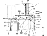
ガスセンサ1は、図1に示すごとく、センサ素子2、素子側絶縁碍子31、大気側絶縁碍子32、ハウジング4、シール5、及び大気側カバー6を有する。センサ素子2は、被測定ガス中の所定のガス成分の濃度を検出する。素子側絶縁碍子31は、センサ素子2を内側に挿通保持する。大気側絶縁碍子32は、センサ素子2の基端側21を覆って内側に大気雰囲気30を形成する。ハウジング4は、素子側絶縁碍子31及び大気側絶縁碍子32を内側に挿通保持する。シール5は、ハウジング4の内周面41と素子側絶縁碍子31の外周面31bとの間にシール材56が充填されてなる。大気側カバー6は、ハウジング4の基端側Y1に固定されている。
本実施例にかかるガスセンサ1につき、図1~図7を用いて説明する。
ガスセンサ1は、図1に示すごとく、センサ素子2、素子側絶縁碍子31、大気側絶縁碍子32、ハウジング4、シール5、及び大気側カバー6を有する。センサ素子2は、被測定ガス中の所定のガス成分の濃度を検出する。素子側絶縁碍子31は、センサ素子2を内側に挿通保持する。大気側絶縁碍子32は、センサ素子2の基端側21を覆って内側に大気雰囲気30を形成する。ハウジング4は、素子側絶縁碍子31及び大気側絶縁碍子32を内側に挿通保持する。シール5は、ハウジング4の内周面41と素子側絶縁碍子31の外周面31bとの間にシール材56が充填されてなる。大気側カバー6は、ハウジング4の基端側Y1に固定されている。
そして、大気側カバー6は、先端側Y2に形成される大径部61と、大径部61よりも基端側Y1に形成されるとともに大径部61の直径よりも小さい直径を有する小径部62と、小径部62と大径部61との間に形成されるとともに付勢部材(皿バネ7)を介して大気側絶縁碍子32の基端面32aを先端側Y2に押圧する外側肩部63と、基端部64に形成された通気孔641とを有する。大気側絶縁碍子32の外周面32bと大径部61の内周面61aとの間には、シール5と隣接する外側空間部50が形成されている。小径部62の内側には、通気孔641と連通する外部経路51が形成されている。外側肩部63には、付勢部材(皿バネ7)に当接する当接部631と、付勢部材(皿バネ7)から離隔する離隔部(非当接部ともいう)632とが形成されている。離隔部632と付勢部材(皿バネ7)との間には、外側空間部50と外部経路51とを連通させる連通路52が形成されている。
以下、ガスセンサ1について詳述する。
ガスセンサ1は、ハウジング4を介して大気側カバー6が外側となるように、排ガス管に取り付けられる。
本例では大気側カバー6は略円筒状を成している。大気側カバー6の軸方向Yの略中央において、外側肩部63は、大気側カバー6の周方向全体に形成されている。図2に示すように、外側肩部63を形成する大気側カバー6の一部が、軸方向Yの先端側Y2に突出して付勢部材としての皿バネ7に当接する当接部631が形成されている。本例では、当接部631は略半球状を成しており、当接部631の先端側Y2の頂点631aが皿バネ7に当接している。また、本例では、当接部631は、図3に示すように、大気側カバー6の周方向に等間隔に12個形成されている。隣り合う二つの当接部631間には、付勢部材としての皿バネ7(図2参照)から離隔する離隔部632が形成されている。そして、図2に示すように、離隔部632と皿バネ7との間の空間が連通路52をなしている。
図1に示すように、大気側カバー6の大径部61の内径は、大気側絶縁碍子32の外径よりも大きくなっており、大径部61の内周面61aと大気側絶縁碍子32の外周面32bとの間に外側空間部50が形成されている。外側空間部50はシール5に隣接しているとともに、連通路52に連通している。
図1に示すように、大気側カバー6の小径部62の内径は、大径部61の内径よりも小さくなっており、小径部62の内側には、センサ素子2の基端側Y1の端部21に接続されるリード線14が位置しているとともに、連通路52に連通する外部経路51が形成されている。
大気側カバー6の基端部64は開口しており、通気孔641が形成されている。大気側カバー6の基端側Y1にはフィルタカバー8が設けられている。フィルタカバー8は略筒状であって、その先端側Y2には大気側カバー6の基端部が嵌入されている。そして、フィルタカバー8の側壁における大気側カバー6の通気孔641の周方向には通気フィルタ65が取り付けられた通気部66が形成されている。通気部66を通じて大気側カバー6の内側に大気が導入される。また、通気フィルタ65により通気部66から水等が侵入することを防止している。そして、通気孔641(通気部66)は外部経路51に連通している。したがって、外側空間部50、連通路52、外部経路51及び通気部66が連通することとなっている。
また、図1に示すごとく、センサ素子2をその中に保持する素子側絶縁碍子31と、素子側絶縁碍子31の基端側Y1に配設される大気側絶縁碍子32とが備えられる。そして、大気側絶縁碍子32の基端面32aには、付勢部材としての皿バネ7が配設されている。皿バネ7は、当接部631と大気側絶縁碍子32との間において、大気側絶縁碍子32を素子側絶縁碍子31の方向へ押し付けるように付勢された状態で配設されている。これにより、大気側絶縁碍子32の先端側Y2の先端面32cと、素子側絶縁碍子31の基端側Y1の基端面31aとが密着して、両者の間の気密性が保たれている。本例では、図1、図4に示すように、皿バネ7は、外側肩部63に沿う環状の弾性部材であって、内周面71及び外周面72はともに平面視円形となっている。皿バネ7の外径は大気側カバー6における小径部62の内径よりも大きく、大径部61の内径よりも若干小さくなっている。
また、ガスセンサ1には、図1に示すごとく、ハウジング4の先端側Y2に被測定ガス側カバー10が配設されている。被測定ガス側カバー10は、外側カバー11と内側カバー12とを有する。そして、外側カバー11と内側カバー12とは、それぞれ複数の被測定ガス導入口13を有する。被測定ガス導入口13から被測定ガスが導入されることにより、被測定ガス側カバー10の内部に被測定ガス雰囲気100が形成される。
図1に示すごとく、シール5は、ハウジング4の基端部に形成された加締め部42により加締められる金属リング54と、センサ素子2とハウジング4とを絶縁するための絶縁部材55と、タルク等からなる粉末シール材56とからなる。シール5によって、ガスセンサ1の先端側Y2に形成される被測定ガス雰囲気100と基端側Y1に形成される大気雰囲気30とが気密的に分離されている。
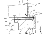
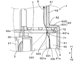
本例のガスセンサ1は、内燃機関による高温・高圧に起因して、シール5に変形が生じる場合がある。そして、シール5に変形が生じた場合には、シール5から被測定ガスGが漏えいすることとなる。ガスセンサ1によれば、図1に示すように、シール5から漏えいした被測定ガスGは、外側空間部50に到達する。そして、外側肩部63に形成された連通路52を介して、外部経路51を流通して通気孔641(通気部66)から大気側カバー6の外部に放出されることとなる。また、大気側カバー6の外側肩部63が皿バネ7を介して大気側絶縁碍子32を素子側絶縁碍子31に向けて押圧するため、両者が密着されて両者の間の気密性が確保されている。これらにより、大気側カバー6内に形成された基準ガスとしての大気雰囲気30に被測定ガスGが流入することが抑制されて、より正確なセンサ出力が得ることができる。そして、連通路52を形成する離隔部632及び当接部631は、大気側カバー6の外側肩部63に形成されているため、大気側絶縁碍子32の基端面32aに凹凸部を形成する場合に比べて、大気側絶縁碍子32の基端面32aにおける応力の集中が緩和され、大気側絶縁碍子32の破損が防止される。また、大気側カバー6の外側肩部63に設けられる離隔部632及び当接部631は、プレス機等で容易に形成することができるため、大気側絶縁碍子32の基端面32aに凹凸部を形成して大気側カバー6の外側肩部63との間に流路を形成する場合に比べて、製造コストを低減される。
また、連通路52は大気側カバー6の外側肩部63に形成されている。そのため、連通路52は、大気側絶縁碍子32に凹凸部を形成して外側肩部63との間に流路を形成する場合に比べて、外気に近い位置に形成されていることから放熱が容易であり、比較的低温となっている。そして、熱泳動効果に基づいて、シール5から漏えいした被測定ガスGは高温である大気側絶縁碍子32の内側よりも低温である連通路52を積極的に流通することとなる。そのため、シール5から漏えいした被測定ガスGが大気側絶縁碍子32の内側の大気雰囲気30に流入することが効果的に抑制され、より正確なセンサ出力を得られる。
当接部631を外側肩部63において先端側Y2に略半球状に突出する形状に形成し、隣り合う当接部631の間に離隔部632が形成されることとした。これに替えて、図5に示すように、当接部631を外側肩部63において先端側Y2に突出するとともに、小径部62の内周面62aの接線方向に延びるリブ状に形成し、隣り合う二つの当接部631の間に離隔部632が形成されることとしてもよい。また。図6及び図7に示すように、当接部631を外側肩部63において基端側Y1に突出するとともに径方向に延びるリブ状の形成し、隣り合う当接部631の間に離隔部632が形成されることとしてもよい。いずれの場合においても、本例と同等の作用効果を奏する。
以上のごとく、本例によれば、被測定ガスが大気側絶縁碍子32の内側の大気雰囲気30に流入することを防止することにより正確なセンサ出力を得るとともに、大気側絶縁碍子32の破損を防止しつつ、製造コストを低減することができるガスセンサ1を提供することができる。
(実施例2)
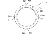
本例のガスセンサ1は、付勢部材として、実施例1のガスセンサ1における皿バネ7(図3)に替えて、図8に示す皿バネ700を備える。皿バネ700は外側肩部63に沿う環状の弾性部材であって、連通路52に連通するガス抜け部520を形成するように複数の切り欠き部701が内周面71に形成されている。四つの切り欠き部701が90°間隔で配置されている。各切り欠き部701は、軸方向Yから見て矩形に形成されており、切り欠き部701の径方向外側面701aは、大気側絶縁碍子32の外周面32bよりも径方向外側に位置している。これにより、図8に示すように、軸方向Yから見て切り欠き部701と大気側絶縁碍子32の外周面32bとの間に連通路52(図9参照)に連通するガス抜け部520が形成される。その他の構成は実施例1の場合と同様である。なお、実施例1の場合と同等の構成には実施例1の場合と同一の符号を付してその説明を省略する。
本例のガスセンサ1は、付勢部材として、実施例1のガスセンサ1における皿バネ7(図3)に替えて、図8に示す皿バネ700を備える。皿バネ700は外側肩部63に沿う環状の弾性部材であって、連通路52に連通するガス抜け部520を形成するように複数の切り欠き部701が内周面71に形成されている。四つの切り欠き部701が90°間隔で配置されている。各切り欠き部701は、軸方向Yから見て矩形に形成されており、切り欠き部701の径方向外側面701aは、大気側絶縁碍子32の外周面32bよりも径方向外側に位置している。これにより、図8に示すように、軸方向Yから見て切り欠き部701と大気側絶縁碍子32の外周面32bとの間に連通路52(図9参照)に連通するガス抜け部520が形成される。その他の構成は実施例1の場合と同様である。なお、実施例1の場合と同等の構成には実施例1の場合と同一の符号を付してその説明を省略する。
図9に示すように、シール5(図1参照)から漏えいした被測定ガスGは、外側空間部50からガス抜け部520を介して連通路52を流通して外部経路51に到達し、通気部66(図1参照)から排出されることとなる。これにより、シール5から漏えいした被測定ガスGがより積極的に連通路52を流通することとなるため、大気側絶縁碍子32の内側の大気雰囲気30(図1参照)に被測定ガスGが流入することが効果的に抑制され、より正確なセンサ出力が得られる。その他、実施例1と同様の作用効果を有する。
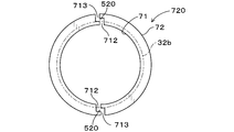
皿バネ700の内周面71に切り欠き部701を形成してガス抜け部520を形成したが、これに替えて、図10に示すように皿バネ710の外周面72に複数の切り欠き部711を形成することにより、ガス抜け部520を形成することができる。例えば、四つの切り欠き部711を90°ごとに等間隔に配置する。また、図11に示すように皿バネ720の外周面72及び内周面71の両方に切り欠き部712、713を形成することにより、ガス抜け部520を形成することもできる。図11に示す例では、両切り欠き部712、713がそれぞれ2か所に設けられるとともに、両切り欠き部712、713が互いに繋がっている。そのため、皿バネ720は2個に分割された状態となっており、両者の隙間にガス抜け部520が形成されることとなっている。また、図12に示すように皿バネ730に貫通孔714を形成することにより、ガス抜け部520を形成してもよい。
(実施例3)
本例のガスセンサ1は、付勢部材として、実施例1のガスセンサ1における付勢部材としての皿バネ7(図3)に替えて、図13に示す波ワッシャ750を備える。波ワッシャ750は、図13及び図14に示すように、外側肩部63に沿う環状の弾性部材であって、基端側Y1に突出するように湾曲する基端側湾出部751と、先端側Y2に突出するように湾曲する先端側湾出部752とが形成されている。そして、図14に示すように、基端側湾出部751と大気側絶縁碍子32との間、及び先端側湾出部752と外側肩部63との間に連通路52に連通するガス抜け部521が形成されている。その他の構成は実施例1の場合と同様である。なお、実施例1の場合と同等の構成には実施例1の場合と同一の符号を付してその説明を省略する。
本例のガスセンサ1は、付勢部材として、実施例1のガスセンサ1における付勢部材としての皿バネ7(図3)に替えて、図13に示す波ワッシャ750を備える。波ワッシャ750は、図13及び図14に示すように、外側肩部63に沿う環状の弾性部材であって、基端側Y1に突出するように湾曲する基端側湾出部751と、先端側Y2に突出するように湾曲する先端側湾出部752とが形成されている。そして、図14に示すように、基端側湾出部751と大気側絶縁碍子32との間、及び先端側湾出部752と外側肩部63との間に連通路52に連通するガス抜け部521が形成されている。その他の構成は実施例1の場合と同様である。なお、実施例1の場合と同等の構成には実施例1の場合と同一の符号を付してその説明を省略する。
図14に示すように、シール5(図1参照)から漏えいした被測定ガスGは、外側空間部50からガス抜け部521及び連通路52を介して外部経路51に到達し、通気部66から排出されることとなる。これにより、実施例2の場合と同様に、より正確なセンサ出力が得られる。
(実施例4)
本例のガスセンサ1は、実施例1における大気側絶縁碍子32(図1参照)に替えて、図15~図17に示す、大気側絶縁碍子320を備える。大気側絶縁碍子320の外周面32bには、連通路52に連通するように軸方向Yに沿って延びる溝部321が形成されている。溝部321の径方向内側面321aは、軸方向Yから見て、皿バネ7の内周面71よりも径方向内側に位置している。これにより、図16に示すように、軸方向Yから皿バネ7の内周面71と大気側絶縁碍子320の溝部321との間にガス抜け部520が形成される。その他の構成は実施例1の場合と同様である。なお、実施例1の場合と同等の構成には実施例1の場合と同一の符号を付してその説明を省略する。
本例のガスセンサ1は、実施例1における大気側絶縁碍子32(図1参照)に替えて、図15~図17に示す、大気側絶縁碍子320を備える。大気側絶縁碍子320の外周面32bには、連通路52に連通するように軸方向Yに沿って延びる溝部321が形成されている。溝部321の径方向内側面321aは、軸方向Yから見て、皿バネ7の内周面71よりも径方向内側に位置している。これにより、図16に示すように、軸方向Yから皿バネ7の内周面71と大気側絶縁碍子320の溝部321との間にガス抜け部520が形成される。その他の構成は実施例1の場合と同様である。なお、実施例1の場合と同等の構成には実施例1の場合と同一の符号を付してその説明を省略する。
図17に示すように、シール5(図1参照)から漏えいした被測定ガスGは、外側空間部50からガス抜け部520及び連通路52を介して外部経路51に到達し、通気部66(図1参照)から排出される。これにより、シール5から漏えいした被測定ガスGがより積極的に連通路52を流通することとなるため、大気側絶縁碍子320の内側の大気雰囲気30(図1参照)に被測定ガスGが流入することが効果的に抑制され、より正確なセンサ出力が得られる。その他、実施例1と同様の作用効果を有する。
なお、実施例2の場合と同様の付勢部材として皿バネ700を備えていてもよい。この場合には、軸方向Yから見て、皿バネ700に形成された切り欠き部701(図8参照)と溝部321とが重なるようにすることとしてもよいし、両者が重ならないようにすることとしてもよい。いずれの場合においても、本例の作用効果に加えて、実施例2における切り欠き部701を設けることによる作用効果が相乗的に奏されるため、より一層正確なセンサ出力が得られる。
図17に示すように、外周溝部321を大気側絶縁碍子320の外周面32bの基端側Y1の端部から先端側Y2の端部まで連続して形成したが、これに替えて、図18に示すように、大気側絶縁碍子330の外周面32bのうち、基端側Y1の基端面32aから軸方向Yにおける中央部まで連続して軸方向Yに沿って形成した外周溝部331としてもよい。外周溝部331の径方向内側面331a、331bのうち、基端側Y1の径方向内側面331aは軸方向Yに平行な面となっており、先端側Y2の径方向内側面331bは先端側Y2に向かうにつれて径方向外側に向かうように、軸方向Yに対して傾斜した面となっている。この場合においても本例と同等の作用効果を奏する。
また、図17に示す外周溝部321に替えて、図19に示すように、大気側絶縁碍子340の外周面32bにおいて、軸方向Yに沿って延びるとともに、先端側Y2に向かうにつれて周方向に広がる外周溝部341を形成してもよい。この場合には、外周溝部341の形状に沿って、シール5(図1参照)から漏えいした被測定ガスGをガス抜け部520に導かれる。これにより、当該被測定ガスGを積極的に連通路52及び外部経路51(図1参照)を通じて外部に排出できるため、大気側絶縁碍子340の内側の大気雰囲気30(図1参照)に被測定ガスGが流入することが効果的に抑制され、より正確なセンサ出力が得られる。
1 ガスセンサ
2 センサ素子
31 素子側絶縁碍子
32、320、330、340 大気側絶縁碍子
4 ハウジング
5 シール
50 外側空間部
51 外部経路
52 連通路
520、521 ガス抜け部
6 大気側カバー
61 大径部
62 小径部
63 外側肩部
7、700、710、720、730 皿バネ(付勢部材)
750 波ワッシャ(付勢部材)
2 センサ素子
31 素子側絶縁碍子
32、320、330、340 大気側絶縁碍子
4 ハウジング
5 シール
50 外側空間部
51 外部経路
52 連通路
520、521 ガス抜け部
6 大気側カバー
61 大径部
62 小径部
63 外側肩部
7、700、710、720、730 皿バネ(付勢部材)
750 波ワッシャ(付勢部材)
Claims (4)
- 被測定ガス中の所定のガス成分の濃度を検出するセンサ素子(2)と、該センサ素子(2)を内側に保持する素子側絶縁碍子(31)と、上記センサ素子(2)の基端側(Y1)を覆って内側に大気雰囲気(30)を形成する大気側絶縁碍子(32、320、330、340)と、上記素子側絶縁碍子(31)及び上記大気側絶縁碍子(32、320、330、340)を内側に保持するハウジング(4)と、該ハウジング(4)の内周面(41)と上記素子側絶縁碍子(31)の外周面(31b)との間に充填されたシール材(56)からなるシール(5)と、上記ハウジング(4)の基端側(Y1)に固定された大気側カバー(6)と、を有するガスセンサ(1)であって、
上記大気側カバー(6)は、先端側(Y2)に形成される大径部(61)と、該大径部(61)よりも基端側(Y1)に形成されるとともに該大径部(61)の直径よりも小さい直径を有する小径部(62)と、該小径部(62)と上記大径部(61)との間に形成されるとともに付勢部材(7、700、710、720、730、750)を介して上記大気側絶縁碍子(32、320、330、340)の基端面(32a)を先端側(Y2)に押圧して上記大気側絶縁碍子(32、320、330、340)を上記素子側絶縁碍子(31)に当接させる肩部(63)と、基端部(64)に形成された通気孔(641)とを有しており、
上記大気側絶縁碍子(32、320、330、340)の外周面(32b)と上記大径部(61)の内周面(61a)との間には、上記シール(5)と隣接する外側空間部(50)が形成されており、
上記小径部(62)の内側には、上記通気孔(641)と連通する外部経路(51)が形成されており、
上記肩部(63)には、付勢部材(7、700、710、720、730、750)に当接する当接部(631)と、上記付勢部材(7、700、710、720、730、750)から離隔する離隔部(632)とが形成されており、該離隔部(632)と上記付勢部材(7、700、710、720、730、750)との間には、上記外側空間部(50)と上記外部経路(51)とを連通させる連通路(52)が形成されているガスセンサ(1)。 - 上記付勢部材(700、710、720、730)は、上記肩部(63)に沿う環状の弾性部材であって、上記連通路(52)に連通するガス抜け部(520)を形成するように切り欠き部(701、711、712、713、714)が形成されている請求項1に記載のガスセンサ(1)。
- 上記付勢部材(750)は、上記肩部(63)に沿う環状の弾性部材であって、基端側(Y1)に突出するように湾曲する基端側湾出部(751)と、先端側(Y2)に突出するように湾曲する先端側湾出部(752)とが形成されており、上記基端側湾出部(751)と上記大気側絶縁碍子(32)との間、及び上記先端側湾出部(752)と上記肩部(63)との間には、上記連通路(52)に連通するガス抜け部(521)が形成されている請求項1に記載のガスセンサ(1)。
- 上記大気側絶縁碍子(320、330、340)の外周面(32b)には、上記連通路(52)に連通するように軸方向(Y)に沿って延びる外周溝部(321、331、341)が形成されている請求項1~3のいずれか一項に記載のガスセンサ(1)。
Priority Applications (2)
| Application Number | Priority Date | Filing Date | Title |
|---|---|---|---|
| US15/539,300 US10088445B2 (en) | 2014-12-25 | 2015-12-11 | Gas sensor |
| EP15872745.3A EP3239703B1 (en) | 2014-12-25 | 2015-12-11 | Gas sensor |
Applications Claiming Priority (2)
| Application Number | Priority Date | Filing Date | Title |
|---|---|---|---|
| JP2014263012A JP6409567B2 (ja) | 2014-12-25 | 2014-12-25 | ガスセンサ |
| JP2014-263012 | 2014-12-25 |
Publications (1)
| Publication Number | Publication Date |
|---|---|
| WO2016104176A1 true WO2016104176A1 (ja) | 2016-06-30 |
Family
ID=56150206
Family Applications (1)
| Application Number | Title | Priority Date | Filing Date |
|---|---|---|---|
| PCT/JP2015/084755 WO2016104176A1 (ja) | 2014-12-25 | 2015-12-11 | ガスセンサ |
Country Status (4)
| Country | Link |
|---|---|
| US (1) | US10088445B2 (ja) |
| EP (1) | EP3239703B1 (ja) |
| JP (1) | JP6409567B2 (ja) |
| WO (1) | WO2016104176A1 (ja) |
Cited By (1)
| Publication number | Priority date | Publication date | Assignee | Title |
|---|---|---|---|---|
| CN110121875A (zh) * | 2016-11-16 | 2019-08-13 | 创控生技股份有限公司 | 智能感测网络 |
Families Citing this family (4)
| Publication number | Priority date | Publication date | Assignee | Title |
|---|---|---|---|---|
| JP6740921B2 (ja) | 2017-02-02 | 2020-08-19 | 株式会社デンソー | ガスセンサ |
| DE102018003247A1 (de) * | 2018-04-20 | 2019-10-24 | Spieth-Maschinenelemente Gmbh & Co. Kg | Festlegevorrichtung |
| JP6962870B2 (ja) * | 2018-06-19 | 2021-11-05 | 日本特殊陶業株式会社 | ガスセンサ |
| JP7298584B2 (ja) * | 2020-10-22 | 2023-06-27 | 株式会社デンソー | ガスセンサ |
Citations (6)
| Publication number | Priority date | Publication date | Assignee | Title |
|---|---|---|---|---|
| JPH09158993A (ja) * | 1995-12-08 | 1997-06-17 | Hitachi Koki Co Ltd | 歯車衝撃緩衝機構 |
| JP2002082089A (ja) * | 2000-06-30 | 2002-03-22 | Denso Corp | ガスセンサ及びその製造方法 |
| JP2007199036A (ja) * | 2006-01-30 | 2007-08-09 | Denso Corp | ガスセンサ |
| JP2007199005A (ja) * | 2006-01-30 | 2007-08-09 | Denso Corp | ガスセンサ |
| JP2007286040A (ja) * | 2006-03-21 | 2007-11-01 | Denso Corp | ガスセンサ |
| JP2013257305A (ja) * | 2012-05-17 | 2013-12-26 | Denso Corp | ガスセンサ |
Family Cites Families (6)
| Publication number | Priority date | Publication date | Assignee | Title |
|---|---|---|---|---|
| DE2504206C3 (de) * | 1975-02-01 | 1981-10-01 | Robert Bosch Gmbh, 7000 Stuttgart | Elektrochemischer Meßfühler für die Bestimmung des Sauerstoffgehalts in Abgasen, insbesondere in Abgasen von Verbrennungsmotoren |
| JP3885789B2 (ja) * | 2002-12-20 | 2007-02-28 | 株式会社デンソー | ガスセンサ |
| JP4172267B2 (ja) * | 2002-12-20 | 2008-10-29 | 株式会社デンソー | ガスセンサ |
| JP4170113B2 (ja) * | 2003-02-26 | 2008-10-22 | 日本特殊陶業株式会社 | ガスセンサ |
| DE102004062189B4 (de) | 2003-12-24 | 2018-10-11 | Denso Corporation | Aufbau eines Gassensors zur Verminderung mechanischer Beschädigung des Sensorelements |
| JP5754338B2 (ja) | 2010-12-17 | 2015-07-29 | 株式会社デンソー | ガスセンサ |
-
2014
- 2014-12-25 JP JP2014263012A patent/JP6409567B2/ja not_active Expired - Fee Related
-
2015
- 2015-12-11 WO PCT/JP2015/084755 patent/WO2016104176A1/ja active Application Filing
- 2015-12-11 US US15/539,300 patent/US10088445B2/en active Active
- 2015-12-11 EP EP15872745.3A patent/EP3239703B1/en not_active Not-in-force
Patent Citations (6)
| Publication number | Priority date | Publication date | Assignee | Title |
|---|---|---|---|---|
| JPH09158993A (ja) * | 1995-12-08 | 1997-06-17 | Hitachi Koki Co Ltd | 歯車衝撃緩衝機構 |
| JP2002082089A (ja) * | 2000-06-30 | 2002-03-22 | Denso Corp | ガスセンサ及びその製造方法 |
| JP2007199036A (ja) * | 2006-01-30 | 2007-08-09 | Denso Corp | ガスセンサ |
| JP2007199005A (ja) * | 2006-01-30 | 2007-08-09 | Denso Corp | ガスセンサ |
| JP2007286040A (ja) * | 2006-03-21 | 2007-11-01 | Denso Corp | ガスセンサ |
| JP2013257305A (ja) * | 2012-05-17 | 2013-12-26 | Denso Corp | ガスセンサ |
Cited By (3)
| Publication number | Priority date | Publication date | Assignee | Title |
|---|---|---|---|---|
| CN110121875A (zh) * | 2016-11-16 | 2019-08-13 | 创控生技股份有限公司 | 智能感测网络 |
| CN110121875B (zh) * | 2016-11-16 | 2022-06-24 | 创控生技股份有限公司 | 智能感测网络 |
| US11788997B2 (en) | 2016-11-16 | 2023-10-17 | Tricorntech Corporation | Smart sensing network |
Also Published As
| Publication number | Publication date |
|---|---|
| JP6409567B2 (ja) | 2018-10-24 |
| EP3239703B1 (en) | 2019-10-30 |
| EP3239703A4 (en) | 2017-11-01 |
| EP3239703A1 (en) | 2017-11-01 |
| JP2016121964A (ja) | 2016-07-07 |
| US10088445B2 (en) | 2018-10-02 |
| US20170356874A1 (en) | 2017-12-14 |
Similar Documents
| Publication | Publication Date | Title |
|---|---|---|
| WO2016104176A1 (ja) | ガスセンサ | |
| JP5934727B2 (ja) | ガスセンサ | |
| JP5682637B2 (ja) | ガスセンサ | |
| JP2008292460A (ja) | ガスセンサ | |
| JP5768766B2 (ja) | 防水栓 | |
| US10465796B2 (en) | Sealing arrangement | |
| US8650933B2 (en) | Gas sensor | |
| US8567234B2 (en) | Gas sensor | |
| JP6348405B2 (ja) | ガスセンサ | |
| JP2016211981A (ja) | ガスセンサ | |
| JP2006145397A (ja) | ガスセンサ | |
| JP2007155517A (ja) | ガスセンサ | |
| US9970910B2 (en) | Gas sensor and method of manufacturing gas sensor | |
| JP6170441B2 (ja) | センサ | |
| JP6641877B2 (ja) | ガスセンサ、及びガスセンサが取り付けられた排気管 | |
| JP2019078711A (ja) | ガスセンサ | |
| JP6890061B2 (ja) | ガスセンサ | |
| JP2015099120A (ja) | ガスセンサ | |
| US20170212074A1 (en) | Gas sensor | |
| JP5767196B2 (ja) | ガスセンサ | |
| US20240125731A1 (en) | Gas sensor and protection member for gas sensor | |
| JP2019074445A (ja) | センサ | |
| JP2007285915A (ja) | ガスセンサ | |
| US20190178861A1 (en) | Gas sensor | |
| JP2020020731A (ja) | ガスセンサ |
Legal Events
| Date | Code | Title | Description |
|---|---|---|---|
| 121 | Ep: the epo has been informed by wipo that ep was designated in this application |
Ref document number: 15872745 Country of ref document: EP Kind code of ref document: A1 |
|
| REEP | Request for entry into the european phase |
Ref document number: 2015872745 Country of ref document: EP |
|
| WWE | Wipo information: entry into national phase |
Ref document number: 15539300 Country of ref document: US |
|
| NENP | Non-entry into the national phase |
Ref country code: DE |