WO2016104149A1 - 係合部品、雌型部材、及び工具交換装置 - Google Patents
係合部品、雌型部材、及び工具交換装置 Download PDFInfo
- Publication number
- WO2016104149A1 WO2016104149A1 PCT/JP2015/084530 JP2015084530W WO2016104149A1 WO 2016104149 A1 WO2016104149 A1 WO 2016104149A1 JP 2015084530 W JP2015084530 W JP 2015084530W WO 2016104149 A1 WO2016104149 A1 WO 2016104149A1
- Authority
- WO
- WIPO (PCT)
- Prior art keywords
- female
- main body
- engagement
- cam
- male
- Prior art date
- Legal status (The legal status is an assumption and is not a legal conclusion. Google has not performed a legal analysis and makes no representation as to the accuracy of the status listed.)
- Ceased
Links
Images







Classifications
-
- B—PERFORMING OPERATIONS; TRANSPORTING
- B23—MACHINE TOOLS; METAL-WORKING NOT OTHERWISE PROVIDED FOR
- B23B—TURNING; BORING
- B23B31/00—Chucks; Expansion mandrels; Adaptations thereof for remote control
- B23B31/02—Chucks
- B23B31/10—Chucks characterised by the retaining or gripping devices or their immediate operating means
- B23B31/103—Retention by pivotal elements, e.g. catches, pawls
-
- B—PERFORMING OPERATIONS; TRANSPORTING
- B25—HAND TOOLS; PORTABLE POWER-DRIVEN TOOLS; MANIPULATORS
- B25J—MANIPULATORS; CHAMBERS PROVIDED WITH MANIPULATION DEVICES
- B25J15/00—Gripping heads and other end effectors
- B25J15/04—Gripping heads and other end effectors with provision for the remote detachment or exchange of the head or parts thereof
- B25J15/0408—Connections means
- B25J15/0425—Connections means having cams
-
- B—PERFORMING OPERATIONS; TRANSPORTING
- B23—MACHINE TOOLS; METAL-WORKING NOT OTHERWISE PROVIDED FOR
- B23B—TURNING; BORING
- B23B31/00—Chucks; Expansion mandrels; Adaptations thereof for remote control
- B23B31/02—Chucks
- B23B31/10—Chucks characterised by the retaining or gripping devices or their immediate operating means
- B23B31/12—Chucks with simultaneously-acting jaws, whether or not also individually adjustable
- B23B31/18—Chucks with simultaneously-acting jaws, whether or not also individually adjustable pivotally movable in planes containing the axis of the chuck
-
- B—PERFORMING OPERATIONS; TRANSPORTING
- B23—MACHINE TOOLS; METAL-WORKING NOT OTHERWISE PROVIDED FOR
- B23B—TURNING; BORING
- B23B2231/00—Details of chucks, toolholder shanks or tool shanks
- B23B2231/40—Chucks having a pivotal retention element in the form of a laterally acting cam
-
- B—PERFORMING OPERATIONS; TRANSPORTING
- B23—MACHINE TOOLS; METAL-WORKING NOT OTHERWISE PROVIDED FOR
- B23Q—DETAILS, COMPONENTS, OR ACCESSORIES FOR MACHINE TOOLS, e.g. ARRANGEMENTS FOR COPYING OR CONTROLLING; MACHINE TOOLS IN GENERAL CHARACTERISED BY THE CONSTRUCTION OF PARTICULAR DETAILS OR COMPONENTS; COMBINATIONS OR ASSOCIATIONS OF METAL-WORKING MACHINES, NOT DIRECTED TO A PARTICULAR RESULT
- B23Q3/00—Devices holding, supporting, or positioning work or tools, of a kind normally removable from the machine
- B23Q3/155—Arrangements for automatic insertion or removal of tools, e.g. combined with manual handling
-
- Y—GENERAL TAGGING OF NEW TECHNOLOGICAL DEVELOPMENTS; GENERAL TAGGING OF CROSS-SECTIONAL TECHNOLOGIES SPANNING OVER SEVERAL SECTIONS OF THE IPC; TECHNICAL SUBJECTS COVERED BY FORMER USPC CROSS-REFERENCE ART COLLECTIONS [XRACs] AND DIGESTS
- Y10—TECHNICAL SUBJECTS COVERED BY FORMER USPC
- Y10T—TECHNICAL SUBJECTS COVERED BY FORMER US CLASSIFICATION
- Y10T279/00—Chucks or sockets
- Y10T279/10—Expanding
- Y10T279/1037—Axially moving actuator
- Y10T279/1041—Wedge
- Y10T279/1045—Internal cone
-
- Y—GENERAL TAGGING OF NEW TECHNOLOGICAL DEVELOPMENTS; GENERAL TAGGING OF CROSS-SECTIONAL TECHNOLOGIES SPANNING OVER SEVERAL SECTIONS OF THE IPC; TECHNICAL SUBJECTS COVERED BY FORMER USPC CROSS-REFERENCE ART COLLECTIONS [XRACs] AND DIGESTS
- Y10—TECHNICAL SUBJECTS COVERED BY FORMER USPC
- Y10T—TECHNICAL SUBJECTS COVERED BY FORMER US CLASSIFICATION
- Y10T279/00—Chucks or sockets
- Y10T279/10—Expanding
- Y10T279/1083—Jaw structure
- Y10T279/1095—Pivoted
-
- Y—GENERAL TAGGING OF NEW TECHNOLOGICAL DEVELOPMENTS; GENERAL TAGGING OF CROSS-SECTIONAL TECHNOLOGIES SPANNING OVER SEVERAL SECTIONS OF THE IPC; TECHNICAL SUBJECTS COVERED BY FORMER USPC CROSS-REFERENCE ART COLLECTIONS [XRACs] AND DIGESTS
- Y10—TECHNICAL SUBJECTS COVERED BY FORMER USPC
- Y10T—TECHNICAL SUBJECTS COVERED BY FORMER US CLASSIFICATION
- Y10T279/00—Chucks or sockets
- Y10T279/17—Socket type
- Y10T279/17231—Pivoted jaws
Definitions
- the present invention relates to an engaging part, a female mold member, and a tool changer, and more particularly to an object applied to an industrial robot.
- a device including a male member attached to the robot side and a female member attached to the tool side is disclosed (for example, Patent Document 1).
- the male member is provided with a protrusion and a cam that can protrude in the radial direction from the protrusion on the male main body.
- the female mold member is formed with a connecting hole into which the projection can be inserted in the female mold body, and an engaging part with which the cam can be engaged is provided on the inner peripheral surface of the connecting hole.
- the male member and the female member are connected when the cam is engaged with the engaging component in a state where the protrusion is inserted into the connecting hole. Further, the male member and the female member can be separated by releasing the engagement between the cam and the engaging part. In this way, the tool changer can change the tool attached to the industrial robot.
- the engaging part has a dispersive surface that can disperse the force received from the cam, so that the male member and the female member are connected with a substantially uniform force without bias.
- An object of the present invention is to provide an engaging member, a female member, and a tool changer that can be reduced in size.
- the engaging component according to the present invention constitutes the female member of a tool changer including a male member that is detachably attached to the main body side of the device and a female member that is detachably attached to the tool side.
- an engagement surface with which a cam provided on the male mold member is engaged, and a force applied from the cam via the engagement surface are applied to the female mold.
- a dispersion surface that transmits to the main body, and the dispersion surface includes a first dispersion surface and a second dispersion surface that are substantially orthogonal to each other, and a cross-sectional shape perpendicular to the longitudinal direction is the first dispersion surface and the first dispersion surface.
- the dispersion surface and the engagement surface are formed in a substantially triangular shape.
- the female member according to the present invention is characterized in that the engaging parts are detachably attached.
- a tool changer according to the present invention includes the female member.
- the cross-sectional shape orthogonal to the longitudinal direction can be formed into a substantially triangular shape by the engagement surface and the first dispersion surface and the second dispersion surface. be able to. Therefore, the female member and the tool changer can be reduced in size as a whole.
- FIG. 2A is a male-type member
- FIG. 2B is a figure of a female-type member.
- FIG. 4A is a rear view
- FIG. 4B is a top view
- FIG. 4C is a front view
- FIG. 4D is a right view.
- FIG. 4A is a rear view
- FIG. 4B is a top view
- FIG. 4C is a front view
- FIG. 4D is a right view.
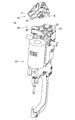
- a tool changer 10 shown in FIG. 1 includes a male member 12 fixed to a tip (not shown) of an arm as a main body of an industrial robot, and a female member 16 fixed to a tool 14. Is provided.
- the male mold member 12 is accurately positioned with respect to the female mold member 16 by inserting a positioning pin 18 provided on the male mold body 17 into a positioning hole 20 formed in the female mold body 19 of the female mold member 16. Is done.
- the tool 14 is not particularly limited, but a spot welding gun is shown in the drawing.
- the male member 12 and the main body, and the female member 16 and the tool 14 are detachably fastened by a fastener (not shown) such as a bolt.
- the main body and the tool 14 can be connected and separated via the tool changer 10.
- the male member 12 includes a male main body 17, a cylinder 22, a coil spring 24, and a cam 26 provided on the male main body 17.
- the coil spring 24 is loaded so that the cylinder 22 can be pushed up in one direction.
- the cylinder 22 rotates the cam 26 by linearly moving in one direction and the other direction (hereinafter referred to as the axial direction).
- the male main body 17 includes a plate-like portion 25 formed in a substantially plate shape, a protrusion 28 protruding from the surface of the plate-like portion 25, a cylinder chamber 30 formed in the plate-like portion 25, and the cylinder
- a cam mechanism housing chamber 39 is formed on the same axis as the chamber 30 and formed in the projection 28.
- the cylinder chamber 30 is formed by closing a hole formed on the other surface of the plate-like portion 25 with a flange 36.
- a first port 32 and a second port 34 are connected to the cylinder chamber 30 side by side in the axial direction. The first port 32 and the second port 34 are connected to an air supply / exhaust mechanism through a pipe (not shown).
- a male contact surface 38 is formed on the periphery of the protruding portion 28.
- the cylinder 22 includes a head 40 disposed in the cylinder chamber 30, a piston 42 provided on the central axis of the head 40, and a first diameter-expanded portion 44 and a second diameter-expanded portion formed on the tip side of the piston 42. 46.
- the head 40 is formed to slide in the cylinder chamber 30 in the axial direction.
- the first port 32 and the second port 34 are connected to one side and the other side in the axial direction of the cylinder chamber 30 with the head 40 interposed therebetween.
- the piston 42 has a proximal end connected to the head 40 and a distal end disposed in the cam mechanism accommodation chamber 39.
- a first diameter-expanded portion 44 and a second diameter-expanded portion 46 are provided at the tip of the piston 42 with an interval in the axial direction.
- the first enlarged diameter portion 44 and the second enlarged diameter portion 46 have a substantially disk shape in which the piston 42 is enlarged in the radial direction.
- the cam 26 is formed of an inverted L-shaped member, and is rotatably supported on the projection 28 of the male main body 17 via a support shaft 27 at a substantially center, and an additional portion 29 is provided on one end side.
- An action portion 31 is formed on the end side.
- the additional portion 29 has a concave surface 33 that is curved on one side across one end of the cam 26 and a flat surface 35 on the other side.
- the action part 31 is formed in an arc shape.
- the additional portion 29 is inserted between the first enlarged diameter portion 44 and the second enlarged diameter portion 46 by arranging the concave surface 33 on the first enlarged diameter portion 44 side and the flat surface 35 on the second enlarged diameter portion 46 side. Has been.
- the cam 26 rotates about the support shaft 27 when the first enlarged diameter portion 44 pushes down the concave surface 33 or the second enlarged diameter portion 46 pushes up the flat surface 35 by the linear motion of the piston 42.
- a plurality of cams 26 are provided on the circumference of the protrusion 28, and in the present embodiment, three cams 26 are equally provided.
- the female mold member 16 has a female mold body 19 and an engagement component 48 fixed to the female mold body 19.
- the female mold body 19 is formed in a substantially plate shape, and has a connecting hole 50 opened in the thickness direction and a female contact surface 52 formed on one surface.
- the connection hole 50 includes a first connection hole 55 formed on the female contact surface 52 side, and a second connection hole 57 that is coaxial with the first connection hole 55 and formed on the other surface side.
- the second connection hole 57 has a larger diameter than the first connection hole 55.
- a plurality of installation portions 59 are provided at circumferential positions corresponding to the positions of the cams 26.
- the installation portion 59 is a groove in which the other surface side of the female main body 19 and the inner surface side of the connection hole 50 are opened, a ceiling surface 51 is formed on the female contact surface 52 side, and the radius of the connection hole 50 is Side surfaces 53 are formed in the direction.
- the ceiling surface 51 and the side surface 53 are configured as flat surfaces.
- An engaging part 48 is installed in the installation part 59.
- the engaging part 48 is an elongated member, and the cross-sectional shape orthogonal to the longitudinal direction is a first distribution surface 56 and a second distribution surface 58 orthogonal to each other as a distribution surface.
- the engagement surface 54 are formed in a substantially triangular shape.
- the first dispersion surface 56 and the second dispersion surface 58 are flat surfaces.
- a plurality of fastening holes 60 are formed in the first dispersion surface 56 only in the longitudinal direction. As shown in the figure, the plurality of fastening holes 60 are arranged only in a line in the longitudinal direction. In the case of this figure, three fastening holes 60 are formed in a line in the longitudinal direction.
- the engagement surface 54 has an arc shape.
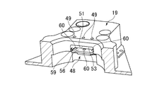
- FIG. 5 is a perspective view showing a state before the engaging component 48 is inserted into the installation portion 59.
- the engaging component 48 is disposed in a state where the longitudinal direction is along the circumferential direction of the connection hole 50 (FIG. 2B), the first dispersion surface 56 is in surface contact with the ceiling surface 51 of the installation portion 59, and the second dispersion surface. 58 is inserted so as to come into surface contact with the side surface 53 of the installation portion 59.
- a through hole 49 is formed in the female main body 19 at a circumferential position corresponding to the fastening hole 60.
- the engaging part 48 is detachably fixed to the female main body 19 by a bolt (not shown) inserted through the through hole 49.
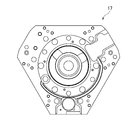
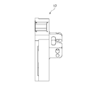
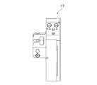
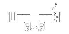
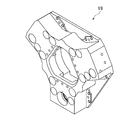
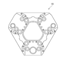
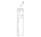
- 6 to 19 are a perspective view and a six-sided view of the male main body 17 and the female main body 19.
- the protrusion 28 of the male member 12 contacts the connecting hole 50 of the female member 16, and the male contact surface 38 (FIG. 2A) contacts the female contact surface 52 (FIG. 2B).
- the gas on one side of the cylinder chamber 30 is discharged from the first port 32 through the air supply / exhaust mechanism with the head 40 interposed therebetween.
- gas is supplied from the second port 34 to the other side of the cylinder chamber 30 with the head 40 interposed therebetween.
- the force of the coil spring 24 is added to the pressure by this gas, and the cylinder 22 moves to the other surface side, that is, rises in this figure.
- the second enlarged diameter portion 46 pushes up the additional portion 29 of the cam 26.
- the cam 26 rotates about the support shaft 27 in the direction of the arrow, that is, clockwise in the figure.
- the cam 26 protrudes radially from the protrusion 28, and the action portion 31 engages with the engagement surface 54 of the engagement component 48. In this way, the male member 12 and the female member 16 are connected.
- a force F is applied from the cam 26 to the engaging surface 54 of the engaging component 48 through the action portion 31.
- Force F given separately in the axial component F Z and the radial component F R, the first dispersion surface 56 axial component F Z is engaging component 48, radial component F R and a second dispersion surface Act on 58.
- the engagement component 48 does not generate a moment in the direction of coming off from the installation part 59, a smaller bolt can be used than before, and the bolt can be fastened and fixed from the ceiling surface 51 side of the installation part 59.
- the size in the height direction can also be reduced.
- the engagement component 48 can be formed in a substantially triangular shape with the engagement surface 54, the first dispersion surface 56, and the second dispersion surface 58 having a cross-sectional shape orthogonal to the longitudinal direction, thereby realizing a reduction in size. can do.
- the female member 16 does not need to be provided with the through holes 49 for inserting the bolts in the radial direction, and thus can be reduced in the radial direction. Therefore, the tool changer 10 can be downsized as a whole.
- the present invention is not limited to the above-described embodiment, and can be appropriately changed within the scope of the gist of the present invention.
- the polygonal male main body 17 and the female main body 19 are illustrated in the front view, but the present invention is not limited to this, and is applied to the circular male main body and female main body in the front view. You can also.
- the present invention is not limited to this, and a liquid may be used. Further, the cam 26 may be driven using a motor.
- first dispersion surface 56 and the second dispersion surface 58 of the engaging component 48 and the ceiling surface 51 and the side surface 53 of the installation portion 59 have been described as being flat surfaces.
- the invention is not limited to this, and may be formed of a curved surface or an uneven surface as long as surface contact is possible.
- the device to which the tool changer is attached is not limited to the industrial robot.
- it may be a balance arm or a hand crane that facilitates movement of a tool attached to the arm, or an object gripped by the tool and work at the movement destination.
- the male member is attached to the arm of the industrial robot on the main body side of the equipment, but the attachment position can be determined at any position on the main body of the equipment according to the equipment configuration, tool type, etc. it can.
Landscapes
- Engineering & Computer Science (AREA)
- Mechanical Engineering (AREA)
- Robotics (AREA)
- Manipulator (AREA)
- Automatic Tool Replacement In Machine Tools (AREA)
- Connection Of Plates (AREA)
Abstract
係合部品(48)は、雄型部材(12)に設けられたカム(26)が係合する係合面(54)と、前記係合面(54)を介して前記カムから付与される力を雌型本体(19)に伝達する分散面とを有し、前記分散面は、直交する第1分散面(56)と第2分散面(58)とからなり、長手方向に直交する断面形状が、前記分散面と前記係合面(54)とにより、略三角形状に形成されていることを特徴とする、小型化することができる係合部材品、雌型部材及び工具交換装置を提供する。
Description
本発明は、係合部品、雌型部材、及び工具交換装置に関し、特に産業用ロボットに適用されるものに関する。
各種機器、例えば産業用ロボットに適用される工具交換装置として、ロボット側に取り付けられる雄型部材と、工具側に取り付けられる雌型部材とを備えるものが開示されている(例えば、特許文献1)。雄型部材は、突起部と、突起部から半径方向に突出可能なカムとが雄型本体に設けられている。雌型部材には、前記突起部が挿入可能な連結穴が雌型本体に形成されており、当該連結穴の内周面に前記カムが係合可能な係合部品が設けられている。工具交換装置は、突起部が連結穴に挿入された状態で、カムが係合部品に係合することにより、雄型部材と雌型部材が連結する。またカムと係合部品の係合を解除することにより、雄型部材と雌型部材は分離し得る。このようにして工具交換装置は、産業用ロボットに取り付ける工具を交換することができる。
上記特許文献1の場合、係合部品は、カムから受ける力を分散させ得る分散面を有することにより、雄型部材と雌型部材が偏りのない略均一な力で連結される。
しかしながら、上記特許文献1の場合、カムから受ける力によって、係合部品にモーメントが生じる。このモーメントによる係合部品の位置ずれを抑えるには、雌型部材の半径方向に複数配置されたボルトにより、係合部品を雌型部材本体に強固に固定する必要がある。そうすると係合部品を小型化することができず、結果として雌型部材及び工具交換装置を大型化せざるを得ないという問題があった。
本発明は、小型化することができる係合部材品、雌型部材及び工具交換装置を提供することを目的とする。
本発明に係る係合部品は、機器の本体側に着脱自在に取り付けられる雄型部材と、工具側に着脱自在に取り付けられる雌型部材とを備える工具交換装置の、前記雌型部材を構成する雌型本体に着脱自在に取り付けられる係合部品において、前記雄型部材に設けられたカムが係合する係合面と、前記係合面を介して前記カムから付与される力を前記雌型本体に伝達する分散面とを有し、前記分散面は、略直交する第1分散面と第2分散面とからなり、長手方向に直交する断面形状が、前記第1分散面と、前記第2分散面と、前記係合面とにより、略三角形状に形成されていることを特徴とする。
本発明に係る雌型部材は、上記係合部品が着脱自在に取り付けられていることを特徴とする。
本発明に係る工具交換装置は、上記雌型部材を備えることを特徴とする。
本発明によれば、係合部品は、長手方向に直交する断面形状が、係合面及び、第1分散面と第2分散面によって、略三角形状に形成することができるので、小型化することができる。したがって雌型部材、及び工具交換装置は、全体として小型化を実現することができる。
以下、図面を参照して本発明の実施形態について詳細に説明する。
(1)全体構成
図1に示す工具交換装置10は、産業用ロボットの本体としてのアームの先端(図示しない)に固定される雄型部材12と、工具14に固定される雌型部材16とを備える。雄型部材12は、雄型本体17に設けられた位置決めピン18を、雌型部材16の雌型本体19に形成された位置決め穴20に挿入することにより、雌型部材16に対し正確に位置決めされる。工具14は特に限定されないが、本図においてはスポット溶接ガンが図示されている。雄型部材12と本体、及び雌型部材16と工具14は、図示しない締結具、例えばボルトにより、着脱自在に締結される。本体と工具14は、工具交換装置10を介して、連結されると共に、分離し得る。
図1に示す工具交換装置10は、産業用ロボットの本体としてのアームの先端(図示しない)に固定される雄型部材12と、工具14に固定される雌型部材16とを備える。雄型部材12は、雄型本体17に設けられた位置決めピン18を、雌型部材16の雌型本体19に形成された位置決め穴20に挿入することにより、雌型部材16に対し正確に位置決めされる。工具14は特に限定されないが、本図においてはスポット溶接ガンが図示されている。雄型部材12と本体、及び雌型部材16と工具14は、図示しない締結具、例えばボルトにより、着脱自在に締結される。本体と工具14は、工具交換装置10を介して、連結されると共に、分離し得る。
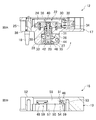
図2Aに示すように、雄型部材12は、雄型本体17と、雄型本体17に設けられた、シリンダ22、コイルバネ24、及びカム26を有する。コイルバネ24は、シリンダ22を一方向に押し上げ得るように装填されている。シリンダ22は、一方向及び他方向(以下、軸方向という)に直線運動することにより、カム26を回転運動させる。
雄型本体17は、略板状に形成された板状部25と、当該板状部25の表面から突出した突起部28と、板状部25内に形成されたシリンダ室30と、当該シリンダ室30の同軸上であって前記突起部28内に形成されたカム機構収容室39とが形成されている。シリンダ室30は、板状部25の他表面に形成された穴を、フランジ36で閉塞することにより、形成される。シリンダ室30には、第1ポート32と第2ポート34が軸方向に並んで連結されている。第1ポート32と第2ポート34は、図示しないが配管を介して給排気機構に連結されている。板状部25の表面には、突起部28の周縁に雄型接触面38が形成されている。
シリンダ22は、シリンダ室30内に配置されるヘッド40と、ヘッド40の中心軸に設けられたピストン42と、ピストン42の先端側に形成された第1拡径部44及び第2拡径部46とを有する。ヘッド40は、シリンダ室30内を軸方向に摺動するように形成されている。第1ポート32と第2ポート34は、ヘッド40を挟んでシリンダ室30の軸方向の一方側と、他方側に連結されている。ピストン42は、基端がヘッド40に連結されており、先端がカム機構収容室39に配置されている。ピストン42の先端には、軸方向に間隔をあけて、第1拡径部44と、第2拡径部46が設けられている。第1拡径部44と第2拡径部46は、ピストン42を半径方向に大きくした略円盤形状を有する。
カム26は、逆L字型の部材で形成されており、略中心において支持軸27を介して雄型本体17の突起部28に回転自在に支持されており、一端側に付加部29、他端側に作用部31が形成されている。付加部29は、カム26の一端を挟んで一側に湾曲した凹面33が形成されており、他側に平坦面35が形成されている。作用部31は円弧形状に形成されている。付加部29は、凹面33を第1拡径部44側に、平坦面35を第2拡径部46側に配置して、第1拡径部44と第2拡径部46の間に挿入されている。カム26は、ピストン42の直線運動によって、第1拡径部44が凹面33を押し下げたり、第2拡径部46が平坦面35を押し上げたりすることにより、支持軸27を中心として回転する。カム26は、突起部28の円周上に複数、本実施形態の場合、3個、均等に設けられている。
図2Bに示すように、雌型部材16は、雌型本体19と、雌型本体19に固定された係合部品48とを有する。雌型本体19は、略板状に形成されており、厚さ方向に開口した連結穴50と、一表面に形成された雌型接触面52とを有する。連結穴50は、雌型接触面52側に形成された第1連結穴55と、第1連結穴55と同軸上であって他表面側に形成された第2連結穴57とからなる。第2連結穴57は、第1連結穴55より径が大きい。第1連結穴55と第2連結穴57の接続部分には、カム26の位置に対応した円周方向の位置に、設置部59が複数、本実施形態の場合、3個設けられている。当該設置部59は、雌型本体19の他表面側及び連結穴50の内面側が開口した溝であって、雌型接触面52側に天井面51が形成されていると共に、連結穴50の半径方向に側面53が形成されている。天井面51及び側面53は平坦面で構成されている。当該設置部59には、係合部品48が設置されている。
図3及び図4A~Dに示すように、係合部品48は、細長い部材であって、長手方向に直交する断面形状が、分散面としての直交する第1分散面56及び第2分散面58と、係合面54とにより、略三角形状に形成されている。第1分散面56と第2分散面58は平坦面で構成されている。第1分散面56には、複数の締結穴60が長手方向にのみ形成されている。本図に示すように、複数の締結穴60は、長手方向に一列にのみ配置されている。本図の場合、締結穴60は、長手方向に一列に3個形成されている。係合面54は、円弧形状を有する。
図5を参照して、係合部品48と設置部59との位置関係について説明する。図5は、係合部品48が設置部59に挿入される前の状態を示す斜視図である。係合部品48は、長手方向が連結穴50(図2B)の円周方向に沿った状態で配置され、設置部59の天井面51に第1分散面56が面接触し、第2分散面58が設置部59の側面53に面接触するように挿入される。雌型本体19には、締結穴60に対応する円周方向の位置に貫通穴49が形成されている。係合部品48は、当該貫通穴49を通じ挿入されたボルト(図示しない)により、雌型本体19に着脱自在に固定される。
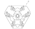
また、図6~図19に、雄型本体17及び雌型本体19の斜視図及び六面図を示す。
(2)動作及び効果
次に、雄型部材12と雌型部材16を連結する動作を説明する。まず、雄型部材12と雌型部材16を同軸上に配置し、位置決めする。この状態で給排気機構を通じて、ヘッド40を挟んでシリンダ室30の一方側に、第1ポート32から流体として気体を供給する。この気体によってヘッド40の一方側の圧力がコイルバネ24の力を上回ると、シリンダ22が他方側へ移動、すなわち下降する(図2A)。これにより第1拡径部44がカム26の付加部29を押し下げる。そうするとカム26は、支持軸27を中心として矢印方向、すなわち図2A中反時計回りに回転する。これによりカム26は、突起部28内に収容される。
次に、雄型部材12と雌型部材16を連結する動作を説明する。まず、雄型部材12と雌型部材16を同軸上に配置し、位置決めする。この状態で給排気機構を通じて、ヘッド40を挟んでシリンダ室30の一方側に、第1ポート32から流体として気体を供給する。この気体によってヘッド40の一方側の圧力がコイルバネ24の力を上回ると、シリンダ22が他方側へ移動、すなわち下降する(図2A)。これにより第1拡径部44がカム26の付加部29を押し下げる。そうするとカム26は、支持軸27を中心として矢印方向、すなわち図2A中反時計回りに回転する。これによりカム26は、突起部28内に収容される。
次いで、図20に示すように、雄型部材12の突起部28を雌型部材16の連結穴50に、雄型接触面38(図2A)が雌型接触面52(図2B)に接触するまで挿入する。この状態で給排気機構を通じて、ヘッド40を挟んでシリンダ室30の一方側の気体を第1ポート32から排出する。同時にヘッド40を挟んでシリンダ室30の他方側へ第2ポート34から気体を供給する。この気体による圧力に、コイルバネ24の力が加わり、シリンダ22は、他表面側へ移動、すなわち本図において上昇する。これにより第2拡径部46がカム26の付加部29を押し上げる。そうするとカム26は、支持軸27を中心として矢印方向、すなわち本図中時計回りに回転する。この回転によって、カム26は突起部28から放射状に突出し、作用部31が係合部品48の係合面54と係合する。このようにして雄型部材12と雌型部材16が連結される。
以上のようにして雄型部材12と雌型部材16が連結されることにより、カム26から作用部31を通じて係合部品48の係合面54に力Fが付与される。力Fは、軸方向成分FZと半径方向成分FRとに分けて考えると、軸方向成分FZが係合部品48の第1分散面56に、半径方向成分FRが第2分散面58に作用する。
本実施形態の工具交換装置10は、係合部品48の第1分散面56に作用する軸方向成分FZより第2分散面58に作用する半径方向成分FRの方が、より大きくなるように構成されている。これにより、従来のように、係合部品48に対し図20中の矢印方向のモーメントが生じないので、係合部品48を雌型本体19に固定する方法を簡略化することができる。すなわち、本実施形態の場合、雌型部材16の半径方向に係合部品48を固定するボルトを複数配置する必要がない。したがって本実施形態の係合部品48は、長手方向に締結穴60を配置するだけで足りるので、幅方向の大きさを小さくすることができる。さらに係合部品48は、設置部59から抜ける方向のモーメントが生じないことから従来に比べ小さいボルトを使用することができ、しかも設置部59の天井面51側からボルトを締めつけて固定できるので、高さ方向の大きさも小さくすることができる。したがって係合部品48は、長手方向に直交する断面形状が、係合面54、第1分散面56、及び第2分散面58によって、略三角形状に形成することができるので、小型化を実現することができる。
また雌型部材16は、半径方向にボルトを挿入する貫通穴49を配置する必要がないので、半径方向に小さくすることができる。したがって工具交換装置10は、全体として小型化を実現することができる。
このように係合部品48の第1分散面56より第2分散面58に、より大きい力を作用させるには、係合面54に係合したときのカム26の回転角度をより大きくすることが有効である。これにより半径方向成分FRを軸方向成分FZより大きくすることができるので、係合部品48の第1分散面56より第2分散面58に、より大きい力を作用させることができる。
(3)変形例
本発明は上記実施形態に限定されるものではなく、本発明の趣旨の範囲内で適宜変更することが可能である。上記実施形態の場合、正面視において多角形状の雄型本体17及び雌型本体19を図示したが、本発明はこれに限らず、正面視において円形状の雄型本体及び雌型本体に適用することもできる。
本発明は上記実施形態に限定されるものではなく、本発明の趣旨の範囲内で適宜変更することが可能である。上記実施形態の場合、正面視において多角形状の雄型本体17及び雌型本体19を図示したが、本発明はこれに限らず、正面視において円形状の雄型本体及び雌型本体に適用することもできる。
上記実施形態の場合、カム26を突起部28の円周上に3個設ける場合について説明したが、本発明はこれに限らず、4個以上設けることとしてもよい。
上記実施形態の場合、流体として気体を用いてシリンダ22を動作させる場合について説明したが、本発明はこれに限らず、液体を用いてもよい。また、モータを用いてカム26を駆動してもよい。
上記実施形態の場合、係合部品48の第1分散面56と第2分散面58、及び、設置部59の天井面51と側面53は、それぞれ平坦面で構成する場合について説明したが、本発明はこれに限らず、面接触可能であれば、曲面や凹凸面で形成してもよい。
上記実施形態では、機器の一例として産業ロボットの場合を説明したが、工具交換装置を取り付ける機器は、産業用ロボットに限定されるものではない。例えばアームに取付けられた工具、あるいはその工具で把持した物の移動や移動先での作業を容易にするバランスアームやハンドクレーンなどであってもよい。また、機器の本体側である産業ロボットのアームに雄型部材を取り付けているが、その取り付け位置は、機器の構成や工具の種類などに応じて、機器の本体の任意の位置に決めることができる。
10 工具交換装置
12 雄型部材
14 工具
16 雌型部材
17 雄型本体
19 雌型本体
26 カム
48 係合部品
54 係合面
56 第1分散面
58 第2分散面
60 締結穴
12 雄型部材
14 工具
16 雌型部材
17 雄型本体
19 雌型本体
26 カム
48 係合部品
54 係合面
56 第1分散面
58 第2分散面
60 締結穴
Claims (4)
- 機器の本体側に着脱自在に取り付けられる雄型部材と、工具側に着脱自在に取り付けられる雌型部材とを備える工具交換装置の、前記雌型部材を構成する雌型本体に着脱自在に取り付けられる係合部品において、
前記雄型部材に設けられたカムが係合する係合面と、
前記係合面を介して前記カムから付与される力を前記雌型本体に伝達する分散面と
を有し、
前記分散面は、略直交する第1分散面と第2分散面とからなり、
長手方向に直交する断面形状が、前記第1分散面と、前記第2分散面と、前記係合面とにより、略三角形状に形成されていることを特徴とする係合部品。 - 長手方向に平行に配置された複数の締結穴を有することを特徴とする請求項1記載の係合部品。
- 請求項1又は2記載の係合部品が着脱自在に取り付けられていることを特徴とする雌型部材。
- 請求項3記載の雌型部材を備えることを特徴とする工具交換装置。
Priority Applications (2)
| Application Number | Priority Date | Filing Date | Title |
|---|---|---|---|
| CN201580067062.7A CN107000217B (zh) | 2014-12-26 | 2015-12-09 | 结合部件、凹型部件及工具交换装置 |
| US15/538,643 US10322455B2 (en) | 2014-12-26 | 2015-12-09 | Engagement component, female member, and tool replacement apparatus |
Applications Claiming Priority (2)
| Application Number | Priority Date | Filing Date | Title |
|---|---|---|---|
| JP2014264304A JP6475979B2 (ja) | 2014-12-26 | 2014-12-26 | 係合部品、雌型部材、及び工具交換装置 |
| JP2014-264304 | 2014-12-26 |
Publications (1)
| Publication Number | Publication Date |
|---|---|
| WO2016104149A1 true WO2016104149A1 (ja) | 2016-06-30 |
Family
ID=56150179
Family Applications (1)
| Application Number | Title | Priority Date | Filing Date |
|---|---|---|---|
| PCT/JP2015/084530 Ceased WO2016104149A1 (ja) | 2014-12-26 | 2015-12-09 | 係合部品、雌型部材、及び工具交換装置 |
Country Status (4)
| Country | Link |
|---|---|
| US (1) | US10322455B2 (ja) |
| JP (1) | JP6475979B2 (ja) |
| CN (1) | CN107000217B (ja) |
| WO (1) | WO2016104149A1 (ja) |
Families Citing this family (7)
| Publication number | Priority date | Publication date | Assignee | Title |
|---|---|---|---|---|
| JP1576821S (ja) * | 2016-08-26 | 2017-05-22 | ||
| CN109129542A (zh) * | 2018-09-08 | 2019-01-04 | 上海辉效工业自动化有限公司 | 自动工具交换装置 |
| CN110900645B (zh) * | 2019-12-10 | 2021-07-30 | 赣州市绿之蓝空气治理有限公司 | 一种机器人抓手用的快速更换机构 |
| CN110900648A (zh) * | 2019-12-10 | 2020-03-24 | 东莞市蓝企信息科技有限公司 | 一种机器人与其抓手的快速装夹机构 |
| CN111940820B (zh) * | 2020-08-07 | 2021-08-24 | 国网江苏省电力有限公司常州供电分公司 | 便于更换锁定的通用通讯接口 |
| CN114654486B (zh) * | 2022-04-26 | 2022-12-20 | 墨影科技(南京)有限公司 | 一种电驱动机械臂末端快换装置及其控制方法 |
| JP2025176357A (ja) * | 2024-05-21 | 2025-12-04 | ニッタ株式会社 | ツールアダプターおよび自動工具交換装置 |
Citations (5)
| Publication number | Priority date | Publication date | Assignee | Title |
|---|---|---|---|---|
| JPH052887U (ja) * | 1991-03-20 | 1993-01-19 | ビー・エル・オートテツク株式会社 | 工具交換装置におけるエアジヨイント構造 |
| JPH07186079A (ja) * | 1993-12-27 | 1995-07-25 | Mishima Kosan Co Ltd | 自動工具交換装置 |
| WO2000027596A1 (en) * | 1998-11-05 | 2000-05-18 | Pascal Kabushiki Kaisha | Tool connecting device for robot hand |
| JP2012213847A (ja) * | 2011-11-02 | 2012-11-08 | B L Auto Tec Kk | 工具交換装置 |
| JP2012250327A (ja) * | 2011-06-03 | 2012-12-20 | Nitta Corp | 自動工具交換装置 |
Family Cites Families (10)
| Publication number | Priority date | Publication date | Assignee | Title |
|---|---|---|---|---|
| JP2002356714A (ja) * | 2001-05-31 | 2002-12-13 | Denki Kogyo Co Ltd | 高周波加熱コイル交換装置及び高周波焼入装置 |
| US7328924B2 (en) * | 2003-12-12 | 2008-02-12 | Phd, Inc. | Adjustable tip assembly |
| DE102005030820B3 (de) * | 2005-07-01 | 2006-08-17 | Ott-Jakob Gmbh & Co. Spanntechnik Kg | Spannvorrichtung |
| US8005570B2 (en) * | 2006-03-14 | 2011-08-23 | Ati Industrial Automation | Robotic tool changer |
| US8209840B2 (en) * | 2006-04-04 | 2012-07-03 | Ati Industrial Automation, Inc. | Rotating coupling for robotic tool changer |
| JP4126074B1 (ja) * | 2007-03-13 | 2008-07-30 | 株式会社スター精機 | ロボットアームカップリング装置 |
| JP5272935B2 (ja) * | 2009-07-09 | 2013-08-28 | 村田機械株式会社 | カップリング装置 |
| DE202012100384U1 (de) * | 2012-02-06 | 2013-05-10 | Kuka Systems Gmbh | Kupplungseinrichtung |
| CN202779872U (zh) * | 2012-08-23 | 2013-03-13 | 顾学华 | 杠杆式浮动爪卡盘机构 |
| ES2762945T3 (es) * | 2015-02-16 | 2020-05-26 | Norgren Automation Solutions Llc | Aparato de desconexión rápida para herramientas modulares |
-
2014
- 2014-12-26 JP JP2014264304A patent/JP6475979B2/ja active Active
-
2015
- 2015-12-09 WO PCT/JP2015/084530 patent/WO2016104149A1/ja not_active Ceased
- 2015-12-09 US US15/538,643 patent/US10322455B2/en active Active
- 2015-12-09 CN CN201580067062.7A patent/CN107000217B/zh active Active
Patent Citations (5)
| Publication number | Priority date | Publication date | Assignee | Title |
|---|---|---|---|---|
| JPH052887U (ja) * | 1991-03-20 | 1993-01-19 | ビー・エル・オートテツク株式会社 | 工具交換装置におけるエアジヨイント構造 |
| JPH07186079A (ja) * | 1993-12-27 | 1995-07-25 | Mishima Kosan Co Ltd | 自動工具交換装置 |
| WO2000027596A1 (en) * | 1998-11-05 | 2000-05-18 | Pascal Kabushiki Kaisha | Tool connecting device for robot hand |
| JP2012250327A (ja) * | 2011-06-03 | 2012-12-20 | Nitta Corp | 自動工具交換装置 |
| JP2012213847A (ja) * | 2011-11-02 | 2012-11-08 | B L Auto Tec Kk | 工具交換装置 |
Also Published As
| Publication number | Publication date |
|---|---|
| CN107000217B (zh) | 2020-07-07 |
| US20170355049A1 (en) | 2017-12-14 |
| JP2016124039A (ja) | 2016-07-11 |
| JP6475979B2 (ja) | 2019-02-27 |
| CN107000217A (zh) | 2017-08-01 |
| US10322455B2 (en) | 2019-06-18 |
Similar Documents
| Publication | Publication Date | Title |
|---|---|---|
| JP6475979B2 (ja) | 係合部品、雌型部材、及び工具交換装置 | |
| JP5697549B2 (ja) | 自動工具交換装置 | |
| JP6545671B2 (ja) | エンドエフェクタ、産業用ロボット、およびその運転方法 | |
| WO2018056061A1 (ja) | 工具交換装置 | |
| JP6930895B2 (ja) | 自動工具交換用カップラー及び自動工具交換装置 | |
| TWI636846B (zh) | O型環安裝裝置、多關節型機器人、及o型環安裝方法 | |
| CA3022620C (en) | Ratchet wrench | |
| US9381596B2 (en) | Welding fixture | |
| CN110854044A (zh) | 半导体设备及其加热装置 | |
| US9429958B2 (en) | Regulator unit | |
| WO2020226060A1 (ja) | 部材交換装置 | |
| KR101440066B1 (ko) | 로봇용 스위블 그리퍼 | |
| CN104552277B (zh) | 一种机械臂 | |
| JP6496495B2 (ja) | 自動工具交換装置 | |
| JP2012000748A (ja) | クランプ装置 | |
| JP2012017838A (ja) | ガスステー用ボールジョイント | |
| US12125600B2 (en) | Mechanical grasping end effector with linear engagement and disengagement movement | |
| US10081063B2 (en) | Expanding locating pin with controlled holding force | |
| CN103256272A (zh) | 气缸 | |
| CN111070145A (zh) | 一种单向扳手 | |
| WO2017094651A1 (ja) | ワーク移送装置 | |
| JP2013129035A (ja) | ハンド装置 | |
| JP2006095645A (ja) | 爪状体、及び作業ロボット用ハンド装置 | |
| JP5948278B2 (ja) | 流体圧シリンダ | |
| JP2011240420A (ja) | 回転工具のソケット構造 |
Legal Events
| Date | Code | Title | Description |
|---|---|---|---|
| 121 | Ep: the epo has been informed by wipo that ep was designated in this application |
Ref document number: 15872718 Country of ref document: EP Kind code of ref document: A1 |
|
| WWE | Wipo information: entry into national phase |
Ref document number: 15538643 Country of ref document: US |
|
| NENP | Non-entry into the national phase |
Ref country code: DE |
|
| 122 | Ep: pct application non-entry in european phase |
Ref document number: 15872718 Country of ref document: EP Kind code of ref document: A1 |