WO2016104000A1 - Fe-BASED SOFT MAGNETIC ALLOY RIBBON AND MAGNETIC CORE COMPRISING SAME - Google Patents
Fe-BASED SOFT MAGNETIC ALLOY RIBBON AND MAGNETIC CORE COMPRISING SAME Download PDFInfo
- Publication number
- WO2016104000A1 WO2016104000A1 PCT/JP2015/082491 JP2015082491W WO2016104000A1 WO 2016104000 A1 WO2016104000 A1 WO 2016104000A1 JP 2015082491 W JP2015082491 W JP 2015082491W WO 2016104000 A1 WO2016104000 A1 WO 2016104000A1
- Authority
- WO
- WIPO (PCT)
- Prior art keywords
- ribbon
- magnetic
- atomic
- soft magnetic
- heat treatment
- Prior art date
Links
Images


Classifications
-
- H—ELECTRICITY
- H01—ELECTRIC ELEMENTS
- H01F—MAGNETS; INDUCTANCES; TRANSFORMERS; SELECTION OF MATERIALS FOR THEIR MAGNETIC PROPERTIES
- H01F1/00—Magnets or magnetic bodies characterised by the magnetic materials therefor; Selection of materials for their magnetic properties
- H01F1/01—Magnets or magnetic bodies characterised by the magnetic materials therefor; Selection of materials for their magnetic properties of inorganic materials
- H01F1/03—Magnets or magnetic bodies characterised by the magnetic materials therefor; Selection of materials for their magnetic properties of inorganic materials characterised by their coercivity
- H01F1/12—Magnets or magnetic bodies characterised by the magnetic materials therefor; Selection of materials for their magnetic properties of inorganic materials characterised by their coercivity of soft-magnetic materials
- H01F1/14—Magnets or magnetic bodies characterised by the magnetic materials therefor; Selection of materials for their magnetic properties of inorganic materials characterised by their coercivity of soft-magnetic materials metals or alloys
- H01F1/147—Alloys characterised by their composition
- H01F1/153—Amorphous metallic alloys, e.g. glassy metals
- H01F1/15308—Amorphous metallic alloys, e.g. glassy metals based on Fe/Ni
-
- C—CHEMISTRY; METALLURGY
- C22—METALLURGY; FERROUS OR NON-FERROUS ALLOYS; TREATMENT OF ALLOYS OR NON-FERROUS METALS
- C22C—ALLOYS
- C22C38/00—Ferrous alloys, e.g. steel alloys
- C22C38/10—Ferrous alloys, e.g. steel alloys containing cobalt
-
- C—CHEMISTRY; METALLURGY
- C21—METALLURGY OF IRON
- C21D—MODIFYING THE PHYSICAL STRUCTURE OF FERROUS METALS; GENERAL DEVICES FOR HEAT TREATMENT OF FERROUS OR NON-FERROUS METALS OR ALLOYS; MAKING METAL MALLEABLE, e.g. BY DECARBURISATION OR TEMPERING
- C21D1/00—General methods or devices for heat treatment, e.g. annealing, hardening, quenching or tempering
- C21D1/04—General methods or devices for heat treatment, e.g. annealing, hardening, quenching or tempering with simultaneous application of supersonic waves, magnetic or electric fields
-
- C—CHEMISTRY; METALLURGY
- C21—METALLURGY OF IRON
- C21D—MODIFYING THE PHYSICAL STRUCTURE OF FERROUS METALS; GENERAL DEVICES FOR HEAT TREATMENT OF FERROUS OR NON-FERROUS METALS OR ALLOYS; MAKING METAL MALLEABLE, e.g. BY DECARBURISATION OR TEMPERING
- C21D6/00—Heat treatment of ferrous alloys
- C21D6/001—Heat treatment of ferrous alloys containing Ni
-
- C—CHEMISTRY; METALLURGY
- C21—METALLURGY OF IRON
- C21D—MODIFYING THE PHYSICAL STRUCTURE OF FERROUS METALS; GENERAL DEVICES FOR HEAT TREATMENT OF FERROUS OR NON-FERROUS METALS OR ALLOYS; MAKING METAL MALLEABLE, e.g. BY DECARBURISATION OR TEMPERING
- C21D6/00—Heat treatment of ferrous alloys
- C21D6/007—Heat treatment of ferrous alloys containing Co
-
- C—CHEMISTRY; METALLURGY
- C21—METALLURGY OF IRON
- C21D—MODIFYING THE PHYSICAL STRUCTURE OF FERROUS METALS; GENERAL DEVICES FOR HEAT TREATMENT OF FERROUS OR NON-FERROUS METALS OR ALLOYS; MAKING METAL MALLEABLE, e.g. BY DECARBURISATION OR TEMPERING
- C21D6/00—Heat treatment of ferrous alloys
- C21D6/008—Heat treatment of ferrous alloys containing Si
-
- C—CHEMISTRY; METALLURGY
- C21—METALLURGY OF IRON
- C21D—MODIFYING THE PHYSICAL STRUCTURE OF FERROUS METALS; GENERAL DEVICES FOR HEAT TREATMENT OF FERROUS OR NON-FERROUS METALS OR ALLOYS; MAKING METAL MALLEABLE, e.g. BY DECARBURISATION OR TEMPERING
- C21D8/00—Modifying the physical properties by deformation combined with, or followed by, heat treatment
- C21D8/02—Modifying the physical properties by deformation combined with, or followed by, heat treatment during manufacturing of plates or strips
- C21D8/0205—Modifying the physical properties by deformation combined with, or followed by, heat treatment during manufacturing of plates or strips of ferrous alloys
-
- C—CHEMISTRY; METALLURGY
- C21—METALLURGY OF IRON
- C21D—MODIFYING THE PHYSICAL STRUCTURE OF FERROUS METALS; GENERAL DEVICES FOR HEAT TREATMENT OF FERROUS OR NON-FERROUS METALS OR ALLOYS; MAKING METAL MALLEABLE, e.g. BY DECARBURISATION OR TEMPERING
- C21D8/00—Modifying the physical properties by deformation combined with, or followed by, heat treatment
- C21D8/02—Modifying the physical properties by deformation combined with, or followed by, heat treatment during manufacturing of plates or strips
- C21D8/0247—Modifying the physical properties by deformation combined with, or followed by, heat treatment during manufacturing of plates or strips characterised by the heat treatment
- C21D8/0263—Modifying the physical properties by deformation combined with, or followed by, heat treatment during manufacturing of plates or strips characterised by the heat treatment following hot rolling
-
- C—CHEMISTRY; METALLURGY
- C21—METALLURGY OF IRON
- C21D—MODIFYING THE PHYSICAL STRUCTURE OF FERROUS METALS; GENERAL DEVICES FOR HEAT TREATMENT OF FERROUS OR NON-FERROUS METALS OR ALLOYS; MAKING METAL MALLEABLE, e.g. BY DECARBURISATION OR TEMPERING
- C21D8/00—Modifying the physical properties by deformation combined with, or followed by, heat treatment
- C21D8/12—Modifying the physical properties by deformation combined with, or followed by, heat treatment during manufacturing of articles with special electromagnetic properties
- C21D8/1244—Modifying the physical properties by deformation combined with, or followed by, heat treatment during manufacturing of articles with special electromagnetic properties the heat treatment(s) being of interest
- C21D8/1261—Modifying the physical properties by deformation combined with, or followed by, heat treatment during manufacturing of articles with special electromagnetic properties the heat treatment(s) being of interest following hot rolling
-
- C—CHEMISTRY; METALLURGY
- C21—METALLURGY OF IRON
- C21D—MODIFYING THE PHYSICAL STRUCTURE OF FERROUS METALS; GENERAL DEVICES FOR HEAT TREATMENT OF FERROUS OR NON-FERROUS METALS OR ALLOYS; MAKING METAL MALLEABLE, e.g. BY DECARBURISATION OR TEMPERING
- C21D9/00—Heat treatment, e.g. annealing, hardening, quenching or tempering, adapted for particular articles; Furnaces therefor
- C21D9/52—Heat treatment, e.g. annealing, hardening, quenching or tempering, adapted for particular articles; Furnaces therefor for wires; for strips ; for rods of unlimited length
-
- C—CHEMISTRY; METALLURGY
- C22—METALLURGY; FERROUS OR NON-FERROUS ALLOYS; TREATMENT OF ALLOYS OR NON-FERROUS METALS
- C22C—ALLOYS
- C22C38/00—Ferrous alloys, e.g. steel alloys
-
- C—CHEMISTRY; METALLURGY
- C22—METALLURGY; FERROUS OR NON-FERROUS ALLOYS; TREATMENT OF ALLOYS OR NON-FERROUS METALS
- C22C—ALLOYS
- C22C38/00—Ferrous alloys, e.g. steel alloys
- C22C38/002—Ferrous alloys, e.g. steel alloys containing In, Mg, or other elements not provided for in one single group C22C38/001 - C22C38/60
-
- C—CHEMISTRY; METALLURGY
- C22—METALLURGY; FERROUS OR NON-FERROUS ALLOYS; TREATMENT OF ALLOYS OR NON-FERROUS METALS
- C22C—ALLOYS
- C22C38/00—Ferrous alloys, e.g. steel alloys
- C22C38/008—Ferrous alloys, e.g. steel alloys containing tin
-
- C—CHEMISTRY; METALLURGY
- C22—METALLURGY; FERROUS OR NON-FERROUS ALLOYS; TREATMENT OF ALLOYS OR NON-FERROUS METALS
- C22C—ALLOYS
- C22C38/00—Ferrous alloys, e.g. steel alloys
- C22C38/02—Ferrous alloys, e.g. steel alloys containing silicon
-
- C—CHEMISTRY; METALLURGY
- C22—METALLURGY; FERROUS OR NON-FERROUS ALLOYS; TREATMENT OF ALLOYS OR NON-FERROUS METALS
- C22C—ALLOYS
- C22C38/00—Ferrous alloys, e.g. steel alloys
- C22C38/04—Ferrous alloys, e.g. steel alloys containing manganese
-
- C—CHEMISTRY; METALLURGY
- C22—METALLURGY; FERROUS OR NON-FERROUS ALLOYS; TREATMENT OF ALLOYS OR NON-FERROUS METALS
- C22C—ALLOYS
- C22C38/00—Ferrous alloys, e.g. steel alloys
- C22C38/10—Ferrous alloys, e.g. steel alloys containing cobalt
- C22C38/105—Ferrous alloys, e.g. steel alloys containing cobalt containing Co and Ni
-
- C—CHEMISTRY; METALLURGY
- C22—METALLURGY; FERROUS OR NON-FERROUS ALLOYS; TREATMENT OF ALLOYS OR NON-FERROUS METALS
- C22C—ALLOYS
- C22C38/00—Ferrous alloys, e.g. steel alloys
- C22C38/12—Ferrous alloys, e.g. steel alloys containing tungsten, tantalum, molybdenum, vanadium, or niobium
-
- C—CHEMISTRY; METALLURGY
- C22—METALLURGY; FERROUS OR NON-FERROUS ALLOYS; TREATMENT OF ALLOYS OR NON-FERROUS METALS
- C22C—ALLOYS
- C22C38/00—Ferrous alloys, e.g. steel alloys
- C22C38/14—Ferrous alloys, e.g. steel alloys containing titanium or zirconium
-
- C—CHEMISTRY; METALLURGY
- C22—METALLURGY; FERROUS OR NON-FERROUS ALLOYS; TREATMENT OF ALLOYS OR NON-FERROUS METALS
- C22C—ALLOYS
- C22C38/00—Ferrous alloys, e.g. steel alloys
- C22C38/16—Ferrous alloys, e.g. steel alloys containing copper
-
- C—CHEMISTRY; METALLURGY
- C22—METALLURGY; FERROUS OR NON-FERROUS ALLOYS; TREATMENT OF ALLOYS OR NON-FERROUS METALS
- C22C—ALLOYS
- C22C45/00—Amorphous alloys
- C22C45/02—Amorphous alloys with iron as the major constituent
-
- H—ELECTRICITY
- H01—ELECTRIC ELEMENTS
- H01F—MAGNETS; INDUCTANCES; TRANSFORMERS; SELECTION OF MATERIALS FOR THEIR MAGNETIC PROPERTIES
- H01F1/00—Magnets or magnetic bodies characterised by the magnetic materials therefor; Selection of materials for their magnetic properties
- H01F1/01—Magnets or magnetic bodies characterised by the magnetic materials therefor; Selection of materials for their magnetic properties of inorganic materials
- H01F1/03—Magnets or magnetic bodies characterised by the magnetic materials therefor; Selection of materials for their magnetic properties of inorganic materials characterised by their coercivity
- H01F1/12—Magnets or magnetic bodies characterised by the magnetic materials therefor; Selection of materials for their magnetic properties of inorganic materials characterised by their coercivity of soft-magnetic materials
- H01F1/14—Magnets or magnetic bodies characterised by the magnetic materials therefor; Selection of materials for their magnetic properties of inorganic materials characterised by their coercivity of soft-magnetic materials metals or alloys
- H01F1/16—Magnets or magnetic bodies characterised by the magnetic materials therefor; Selection of materials for their magnetic properties of inorganic materials characterised by their coercivity of soft-magnetic materials metals or alloys in the form of sheets
-
- C—CHEMISTRY; METALLURGY
- C21—METALLURGY OF IRON
- C21D—MODIFYING THE PHYSICAL STRUCTURE OF FERROUS METALS; GENERAL DEVICES FOR HEAT TREATMENT OF FERROUS OR NON-FERROUS METALS OR ALLOYS; MAKING METAL MALLEABLE, e.g. BY DECARBURISATION OR TEMPERING
- C21D6/00—Heat treatment of ferrous alloys
-
- C—CHEMISTRY; METALLURGY
- C22—METALLURGY; FERROUS OR NON-FERROUS ALLOYS; TREATMENT OF ALLOYS OR NON-FERROUS METALS
- C22C—ALLOYS
- C22C2202/00—Physical properties
- C22C2202/02—Magnetic
-
- H—ELECTRICITY
- H01—ELECTRIC ELEMENTS
- H01F—MAGNETS; INDUCTANCES; TRANSFORMERS; SELECTION OF MATERIALS FOR THEIR MAGNETIC PROPERTIES
- H01F38/00—Adaptations of transformers or inductances for specific applications or functions
- H01F38/20—Instruments transformers
Definitions
- the present invention relates to a Fe-based soft magnetic alloy ribbon suitable for various magnetic parts such as current transformers, noise countermeasure parts, high frequency transformers, choke coils, accelerator cores, and a magnetic core using the same.
- various magnetic parts such as current transformers, noise countermeasure parts, high-frequency transformers, choke coils, and accelerator cores include soft ferrites, amorphous soft magnetic alloys, and permalloys that exhibit high magnetic permeability and low core loss characteristics.
- a magnetic core made of a soft magnetic material such as a nanocrystalline soft magnetic alloy is used.
- soft ferrite is excellent in high frequency characteristics, but has a low saturation magnetic flux density Bs and inferior in temperature characteristics, so that it is easily magnetically saturated, and in particular, a current transformer or choke coil in which direct current may be superimposed.
- a current transformer or choke coil in which direct current may be superimposed.
- Fe-based amorphous alloys represented by the Fe-Si-B system do not show BH curves with good linearity even when heat-treated in a magnetic field. There are drawbacks such as loud noise.
- the Co-based amorphous alloy has disadvantages such that the saturation magnetic flux density is as low as 1 T or less, the parts become large, the thermal instability causes a large change with time when the temperature rises, and the raw material is expensive. .
- Fe-based nanocrystalline alloy ribbons that exhibit superior soft magnetic properties compared to the soft magnetic materials described above are suitable for pulse power applications such as earth leakage breakers, current sensors, current transformers, common mode choke coils, high frequency transformers, and accelerators. It is known to be suitable for magnetic core materials.
- Typical composition systems of the Fe-based nanocrystalline alloy ribbon include Fe—Cu— (Nb, Ti, Zr, Hf, Mo, W, Ta) —Si—B based alloys and Fe—Cu— (Nb, Ti , Zr, Hf, Mo, W, Ta) -B alloys and the like are known (Patent Documents 1 and 2).
- Fe-based nanocrystalline alloy ribbons are usually produced by a method of rapidly cooling from the liquid phase to produce amorphous alloy ribbons, processing them into magnetic core shapes as necessary, and then microcrystallizing them by heat treatment.
- Single roll method, twin roll method, centrifugal quenching method, etc. are known as methods for producing alloy ribbons by quenching from the liquid phase.
- the mainstream is the single roll method.
- Fe-based nanocrystalline alloys are microcrystallized amorphous alloys produced by these methods, exhibiting high saturation magnetic flux density and excellent soft magnetic properties similar to those of Fe-based amorphous alloys. It is known that the change is small and the temperature characteristics are excellent.
- choke coils used in a DC superimposed state or in an asymmetrical AC excitation state or current transformers in which an asymmetrical AC current such as a half-wave sine wave AC current flows in the coil.
- a magnetic core material used for (CT) or the like a material showing a BH curve excellent in constant magnetic permeability is used so that the material is not magnetically saturated.
- CT magnetic core material
- a material having a relative magnetic permeability of about 1000 to 3000 is used.
- a magnetic material capable of accurately measuring the electric energy from the asymmetric current waveform is required. It has become.
- a material having a low residual magnetic flux density, a low hysteresis and a good BH curve is used, and Co or Ni subjected to heat treatment in a magnetic field is used. It has been reported that a magnetic core (iron core) made of a Fe-based soft magnetic alloy ribbon containing the alloy exhibits suitable characteristics (Patent Documents 5, 6, and 7).
- the present inventors have found that a ribbon having a specific cross-sectional structure made of an Fe-based soft magnetic alloy has excellent BH curve linearity, low residual magnetic flux density Br, and low BH curve hysteresis.
- the present inventors have found that (the coercive force Hc is small), the change in the incremental magnetic permeability with respect to the superimposed magnetic field is small, and excellent characteristics can be solved, and the above-described problems can be solved.
- the present invention is a ribbon made of an Fe-based soft magnetic alloy containing 5 atomic% to 20 atomic% of Co and 0.5 atomic% to 1.5 atomic% of Cu,
- This is a Fe-based soft magnetic alloy ribbon in which a Cu-concentrated region is present immediately below the surface and a Co-concentrated region is present immediately below the Cu-concentrated region.
- the Co content is b atomic% and the Ni content is c atomic%
- 15 atomic% or less of Ni is included so as to satisfy the relationship of 0.5 ⁇ c / b ⁇ 2.5.
- the present invention is a magnetic core constituted by using the above-described Fe-based soft magnetic alloy ribbon of the present invention, and the magnetic core of the present invention is a magnetic core used for a current transformer for detecting a half-wave sine wave alternating current. It is.
- the Fe-based soft magnetic alloy ribbon of the present invention has excellent BH curve linearity, low residual magnetic flux density Br, low hysteresis of BH curve (small coercive force Hc), and with respect to the excitation magnetic field. Since it is a soft magnetic material having a small change in magnetic permeability, a high-performance magnetic core used for various magnetic components can be provided using the soft magnetic material.
- FIG. 6 is a diagram showing a heat treatment pattern used in Example 2.
- the magnetic core formed using this thin ribbon also exhibits the same excellent characteristics.
- the present invention when the present invention is applied to a small-diameter core, the induced magnetic anisotropy of the surface of the ribbon is easily induced, and the stress generated in the Co-enriched region near the surface of the ribbon due to heat treatment in a magnetic field ⁇
- the magnetic anisotropy due to the magnetostrictive effect can be increased, and disturbance of the magnetic anisotropy can be suppressed.
- the Fe-based soft magnetic alloy ribbon of the present invention has a specific component composition. Specifically, it contains 20 atomic percent or less of Co and 0.5 atomic percent or more and 1.5 atomic percent or less of Cu.
- Co 5 atomic% or more and 20 atomic% or less
- Co (cobalt) has an effect of increasing the induced magnetic anisotropy and contributes to a low magnetic permeability. Therefore, it is essential in the Fe-based soft magnetic alloy ribbon of the present invention. It is an element, and is 5 atomic% or more and 20 atomic% or less. When the amount of Co is less than 5 atomic%, a clear Co concentrated region may not be generated. If the amount of Co is too small, the effect of increasing the induced magnetic anisotropy due to Co is reduced, the magnetic permeability is not reduced, and the linearity of the BH loop may be deteriorated.
- Cu is an essential element in the Fe-based soft magnetic alloy ribbon of the present invention, and is 0.5 atomic% or more and 1.5 atomic% or less. To do.
- the amount of Cu is contained at 0.5 atomic% or more, since the Cu cluster acts as a heterogeneous nucleation site at the time of crystallization at the time of producing the ribbon, a ribbon having a uniform and fine structure can be obtained.
- the amount of Cu is less than 0.5 atomic%, the number density of Cu clusters is insufficient, and the crystal grain structure seen in the cross-sectional structure of the ribbon is a structure in which fine crystals and slightly coarse crystals are mixed.
- Such a ribbon is an excellent soft magnetism when the average crystal grain size of bcc crystal grains dispersed in the amorphous matrix is 30 nm or less, and the average crystal grain size is 5 to 20 nm. Is obtained.
- such a ribbon has a volume fraction of the crystal phase of 50% or more and a typical crystal phase volume fraction of about 60 to 80%.
- Cu forms a large number of Cu clusters inside the ribbon as described above, but tends to segregate because it hardly dissolves in Fe. Therefore, Cu segregates in the vicinity of the boundary between the oxide layer on the surface of the ribbon and the alloy layer inside the ribbon, and a Cu concentrated region is easily formed.
- a Co-enriched region generated inside the ribbon can be generated immediately below the Cu-enriched region depending on the heat treatment conditions.
- the concentration of Cu and Co is increased by subjecting the ribbon to a heat treatment in a magnetic field.
- the induced magnetic anisotropy of the conversion region increases. This makes it possible to reduce the dispersion of anisotropy due to the stress that occurs during the preparation and processing of ribbons and remains after heat treatment, and to disturb the magnetic anisotropy (direction of easy magnetization) caused by the stress-magnetostriction effect, etc.
- the peak concentration of the Co-enriched region is the average of the Co concentrations measured in the range from 0.1 ⁇ m to 0.2 ⁇ m in depth from the surface of the ribbon. It is preferable that it is 1.02 times or more and 1.20 times or less with respect to the value.
- the peak concentration in the Co-enriched region is less than 1.02 times the average value, the above-described property improvement effect may be insufficient.
- the peak concentration in the Co-enriched region exceeds 1.20 times the average value of the war record, the influence of the change in induced magnetic anisotropy due to the change in the Co concentration on the surface of the ribbon becomes large. The shape may be deteriorated.
- Co concentration and Cu concentration are determined by using the glow discharge optical emission spectrometry (GD-OES), the Co content in the thickness direction (depth direction) of the ribbon and the Cu content measured using Glow Discharge-Optical Emission Spectroscopy (GD-OES). It can be shown by content.
- the raw material contains Ni which is cheaper than Co.
- Ni like Co, has the effect of increasing the induced magnetic anisotropy, and contributes to lowering the magnetic permeability.
- the addition amount (atomic%) of Ni and Co to Fe is the same, the induced magnetic anisotropy can be made larger than that of Co, and the magnetic permeability can be made smaller.
- the melting point is lowered when the content ratio of Co or Ni with respect to Fe is increased, the ribbon can be produced by lowering the casting temperature accordingly. For this reason, it becomes easy to manufacture the ribbon and it can be expected to improve the life of the refractory.
- the ribbon when the ribbon contains an appropriate amount of Ni, a ribbon having preferable characteristics as described above may be obtained as compared with the case where Ni is not contained. If the Ni effect is used, the amount of Co corresponding to the improvement in characteristics due to the addition of Ni can be reduced, so that a thin ribbon that does not contain Ni and has the same characteristics as when the amount of Co is not reduced can be produced at low cost. can do. As described above, the ribbon that exhibits the effect by the total amount of Co and Ni has substantially the same characteristics as the ribbon that does not contain Ni and does not reduce the amount of Co, and further reduction in raw material costs can be expected.
- the ribbon may contain 4 atomic% or more and 15 atomic% or less of Ni. preferable.
- the Co-enriched region required in the present invention will not be generated. Inconveniences such as a narrow adjustment range of appropriate heat treatment conditions and a tendency of the surface to be easily crystallized when a ribbon is produced.
- Si helps the formation of an amorphous phase when manufacturing a ribbon.
- Si improves the high-frequency characteristics by increasing the magnetostriction by improving the soft magnetic characteristics by reducing the coercive force Hc of the ribbon or the magnetic core formed by using the ribbon, and by increasing the resistivity.
- B contributes to amorphization when manufacturing a ribbon.
- the presence of B in the amorphous matrix around the ribbon crystal grains after heat treatment contributes to the refinement of the crystal grain structure of the ribbon and reduces the coercive force Hc and improves the soft magnetic properties. The effect to do.
- M contributes to refinement of crystal grains after heat treatment of the ribbon.
- Cr, Mn, Ti, Zr, Hf, P, Ge, and the like are used as necessary for the purpose of improving the corrosion resistance of the ribbon, various magnetic properties, or facilitating the production of the ribbon.
- Ga, Al, Sn, Ag, Au, Pt, Pd, Sc, a molten metal containing a white metal group element, and the like can be used.
- Impurities include elements such as C, N, S, and O, and it has been confirmed that C is particularly likely to be mixed. Mixing of these impurity elements is permissible as long as it does not affect the soft magnetic properties and fabrication of the ribbon.
- the allowable value is less than 1.0% by mass based on the experience of the present inventor, and is considered to be preferably 0.5% by mass or less.
- a magnetic core according to the present invention comprising the ribbon can be obtained.
- the magnetic core according to the present invention is suitable for applications such as a current transformer, a choke coil for a large current and a large capacity, a high frequency transformer, and a pulse power core, and particularly a distorted current such as a half-wave sine wave alternating current. This is suitable for use as a current transformer for detecting an alternating current in which a direct current component is superimposed on.
- the magnetic core according to the present invention is manufactured as a wound magnetic core by winding an Fe-based soft magnetic alloy ribbon, and in general, in order to prevent the magnetic properties from being deteriorated by applying stress to the magnetic core.
- an Fe-based soft magnetic alloy ribbon Used in a resin case.
- powder such as alumina, silica, magnesia, or the like may be formed on the surface of the ribbon to form an insulating state between adjacent ribbons. is there.
- the ribbon is made of copper alloy that is melted by melting a material having the desired alloy composition in a crucible or the like, and is rotated at a peripheral speed of 20 m / s to 40 m / s from a slit provided in a nozzle of the crucible or the like. It can be produced by a method of jetting onto the surface of the roll and quenching.
- the ribbon produced by such a method is in a state where the main phase is in an amorphous phase, and can be slit, cut, and punched as necessary.
- the typical thickness (plate thickness) of the ribbon is 5 ⁇ m to 50 ⁇ m, and the width capable of mass production is 0.5 mm to several hundred mm. Moreover, it can produce in the form of a magnetic core by winding the ribbon which can be produced with the method mentioned above.
- the thin ribbon or the magnetic core manufactured by the above-described method has a predetermined soft magnetic property through, for example, a first heat treatment process, a second heat treatment process, and a third heat treatment process described below.
- a magnetic field having a strength at which the ribbon or magnetic core is magnetically saturated at a temperature of at least 200 ° C. and not more than 600 ° C If the magnetic field to be applied is weak, the magnetization direction of the alloy is not perfectly aligned with the magnetic field application direction, so that regions with different easy magnetization directions are formed inside the ribbon or magnetic core,
- the magnetic field to be applied is usually a DC magnetic field, but an AC magnetic field or a continuous repetitive pulsed magnetic field can also be applied.
- the strength of a typical magnetic field to be applied can be adjusted according to the shape of the ribbon or magnetic core, but if a DC magnetic field is applied in the width direction of the ribbon or the height direction of the magnetic core, it is 80 kA. / M to about 500 kA / m is preferable.
- the ribbon or magnetic core is heated to a first temperature range of 350 ° C. or more and 460 ° C. or less at a rate of 1 ° C./min or more and 20 ° C./min or less, and then 15 minutes or more and 120 minutes or less.
- This is a heat treatment process that is held for a period of time.
- the main purpose of the first heat treatment process is to make the internal temperature of the ribbon or magnetic core uniform and to promote the generation of a Cu-enriched region directly below the surface of the ribbon.
- an appropriate set temperature and holding time of the first temperature range are involved in advancing the generation of the Co concentrated region immediately below the Cu concentrated region.
- the first temperature range which is the holding temperature in the first heat treatment process, is preferably 350 ° C. or more and 460 ° C. or less.
- the rate of temperature rise is preferably 1 ° C./min or more and 20 ° C./min or less, and if it is less than 1 ° C./min, the productivity decreases, and if it exceeds 20 ° C./min, the internal temperature of the ribbon or magnetic core is made uniform Insufficient generation of the Cu-enriched region tends to cause variations in magnetic characteristics.
- the holding time in the first temperature range is preferably 15 minutes or more and 120 minutes or less. If the holding time is less than 15 minutes, the internal temperature of the ribbon or magnetic core becomes non-uniform, which tends to cause variations in magnetic properties, and exceeds 120 minutes. Reduces productivity.
- the second heat treatment process is performed subsequent to the first heat treatment process, and the ribbon or the magnetic core is moved at a rate of 0.3 ° C./min to 5 ° C./min up to a second temperature range of 500 ° C. to 600 ° C.
- This is a heat treatment process in which the temperature is raised and then maintained for 15 minutes to 120 minutes.
- uniform nanocrystals are controlled while suppressing the temperature rise due to crystallization heat generated by the precipitation of nanocrystal grains in the amorphous matrix of the ribbon.
- the main purpose is to generate a grain structure and to proceed with the generation of a Cu-enriched region immediately below the surface of the ribbon and a Co-enriched region immediately below it.
- the second temperature range which is the holding temperature in the second heat treatment process, is preferably 500 ° C. or more and 600 ° C. or less, and if it is less than 500 ° C., the proportion of the amorphous matrix becomes excessive and the linearity of the BH curve deteriorates.
- the coercive force Hc is likely to increase, and if it exceeds 600 ° C., the coercive force Hc tends to increase.
- the rate of temperature rise is preferably 0.3 ° C./min or more and 5 ° C./min or less. When the rate is less than 0.3 ° C./min, the productivity is lowered.
- the holding time in the second temperature range is preferably 15 minutes or more and 120 minutes or less. If the holding time is less than 15 minutes, the temperature difference inside the ribbon or the magnetic core becomes large and the linearity of the BH loop deteriorates or the magnetic characteristics vary. If it exceeds 120 minutes, productivity will decrease.
- the third heat treatment process is performed subsequent to the second heat treatment process, and the ribbon or magnetic core is cooled to a third temperature range of 200 ° C. or lower at a rate of 1 ° C./min to 20 ° C./min. And a heat treatment process of cooling while not disturbing the magnetic anisotropy induced in the second heat treatment process.
- the rate of temperature decrease is preferably 1 ° C / min or more and 20 ° C / min or less, and if it is less than 1 ° C / min, it is unsatisfactory because the productivity decreases, and if it exceeds 20 ° C / min, it is caused by the contraction of the ribbon.
- the linearity of the BH curve is likely to deteriorate due to the generated stress.
- the magnetic field in the third heat treatment process it is preferable to apply the magnetic field in the third heat treatment process until the temperature reaches 200 ° C. or lower.
- the application of a magnetic field is stopped in a temperature range higher than 200 ° C., the shape of the BH loop is disturbed and the coercive force Hc tends to increase.
- the first, second, and third heat treatment processes described above can usually be performed in an inert gas atmosphere or a nitrogen gas atmosphere.
- the dew point of the atmospheric gas is preferably ⁇ 30 ° C. or less, more preferably ⁇ 60 ° C. or less, and if it exceeds ⁇ 30 ° C., coarse crystal grains having a particle size exceeding 30 nm are formed on the surface of the ribbon.
- the coercive force Hc tends to increase.
- Example 1 By a single roll method using a Cu—Be alloy roll with an outer diameter of 280 mm rotating at a peripheral speed of 30 m / s, atomic percent, Co is 11.1%, Ni is 10.2%, Si Is 11.0%, B is 9.1%, Nb is 2.7%, Cu is 0.8%, and the balance is Fe and inevitable impurities, and the width is 5 mm and the average thickness is 20.2 ⁇ m.
- An Fe-based alloy ribbon was prepared. Ni / Co in this ribbon is about 0.92. Next, the produced ribbon was wound around an outer diameter of 19 mm and an inner diameter of 15 mm to produce a magnetic core (winding core).
- the analysis depth measured the sputter
- the X-ray diffraction of the ribbon was performed. From the results of X-ray diffraction, it was confirmed that fine crystal grains mainly composed of Fe of bcc structure were formed inside the ribbon, and the average grain diameter of the crystal grains was about 18 nm from the half-value width of the diffraction peak. It was.
- FIG. 2 shows the analysis results of Co (curve 1 in the figure) and Cu (curve 2 in the figure) by GDOES on the free surface side of the ribbon. It was confirmed that there was a Cu enriched region indicated by the steep peak 2a immediately below the surface of the ribbon, and a Co enriched region indicated by the mountain-shaped peak 1a immediately below it. Although not shown in the figure, from the GDOES analysis result on the roll contact surface side of the ribbon, a Cu enriched region exists on the surface of the ribbon, and a Co enriched region exists directly below it, as on the free surface side. Make sure you do.
- the concentration at the peak 1a of the Co-enriched region is 11.8 atomic%
- the average value of the Co concentration measured in the range where the depth from the surface of the ribbon is 0.1 ⁇ m to 0.2 ⁇ m is It was 11.1 atomic%, and the concentration at the peak 1a with respect to the average value was 1.063 times.
- the concentration at the peak 2a of the Cu enriched region is 5.9 atomic%
- the average value of the Cu concentration measured in the range of 0.1 ⁇ m to 0.2 ⁇ m in depth from the surface of the ribbon is 0.
- the concentration at peak 2a with respect to the average value was 7.375 times.
- FIG. 3 shows a thin-band DC BH curve.
- This DC BH curve has a small slope and good linearity, has a flat overall shape and has a residual magnetic flux density of 0.005T.
- the coercive force Hc was 2.5 A / m.
- the incremental relative permeability mu r ⁇ is the 1 kHz
- the DC superposition magnetic field is 1610 0A / m
- a 1660 DC superposition magnetic field 200A / m the change to the magnetic field of the magnetic permeability is smaller is confirmed.
- Example 2 In the same manner as in Example 1, in atomic%, Co is 3.1%, Ni is 10.1%, Si is 10.9%, B is 8.9%, Nb is 2.7%, Cu is An Fe-based alloy ribbon having a width of 25 mm and an average thickness of 20.0 ⁇ m was prepared using a molten metal consisting of 0.8% and the balance being Fe and inevitable impurities. The Ni / Co in this ribbon is about 3.26. Next, similarly to Example 1, the produced ribbon was wound around an outer diameter of 19 mm and an inner diameter of 15 mm to produce a magnetic core (winding core), and 300 kA in the height direction of the wound core (the width direction of the ribbon). Heat treatment was performed while applying a magnetic field of / m.
- the heat treatment pattern shown in FIG. 4 (temperature increase rate 3.6 ° C./min in step 4a, holding temperature 560 ° C. and holding time 5 min in step 4b, and cooling rate 2.
- the heat treatment in a nitrogen gas atmosphere by 7 ° C./min and the temperature was lowered to room temperature was intentionally used.
- This is a heat treatment pattern that does not have the holding process in the first temperature range of the first heat treatment process and the temperature raising process of the second heat treatment process, and a clear Co-enriched region is not generated inside the ribbon.
- the magnetic field (H) was 280 kA / m, and it was applied in the entire process of heat treatment under the conditions shown in FIG. 4 in the width direction of the alloy ribbon (the height direction of the magnetic core).
- FIG. 5 shows the analysis results of Co (curve 1 in the figure) and Cu (curve 2 in the figure) by GDOES on the free surface side of the ribbon (comparative example). Although there is a Cu enriched region indicated by a steep peak 2a immediately below the surface of the ribbon, a clear peak is not shown in the shoulder 1b of the Co curve 1 immediately below the Co enriched region. The existence of could not be confirmed.
- the change of the direct current BH curve and the permeability with respect to the DC superimposed magnetic field was measured using this thin wound core (comparative example), the residual magnetic flux density Br was 0.04 T, and the coercive force Hc was 7. 2 A / m.
- the incremental relative permeability mu r ⁇ is the 1 kHz
- DC superposition magnetic field was 2420 at 200A / m.
- Example 2 According to the same method as in Example 1, 9.2% Co, 11.9% Ni, 10.9% Si, 9.1% B, 9.1% B, 2.7% Nb, Cu An Fe-based alloy ribbon having a width of 10 mm and an average thickness of 18.3 ⁇ m was prepared using a molten metal composed of 0.8% and the balance Fe and inevitable impurities. The Ni / Co in this ribbon is about 1.29. Next, the produced ribbon was wound around an outer diameter of 24 mm and an inner diameter of 18 mm to produce a plurality of magnetic cores (winding cores).
- the above-described first heat treatment process (heating rate HR1, holding temperature Ta1, and holding time t1 shown in Table 1) while applying a magnetic field of 320 kA / m in the height direction (in the width direction of the ribbon) of the produced magnetic core, Including the second heat treatment process (temperature increase rate HR2 and holding temperature Ta2 and holding time t2 shown in Table 1) and the third heat treatment process (temperature reduction rate CR3 and temperature drop target temperature 190 ° C. shown in Table 1), In the subsequent process 5a, air cooling was performed, and heat treatment was performed in a nitrogen gas atmosphere according to the heat treatment pattern shown in FIG.
- the magnetic field (H) was 280 kA / m, and was applied in the whole process up to 170 ° C. in the temperature lowering process in the width direction of the alloy ribbon (the height direction of the magnetic core).
- the peak value of Co concentration is 1 to the average value of Co concentration measured in the range of 0.1 ⁇ m to 0.2 ⁇ m in depth from the surface of the ribbon. It was in the preferable range of 0.02 times or more and 1.20 times or less.
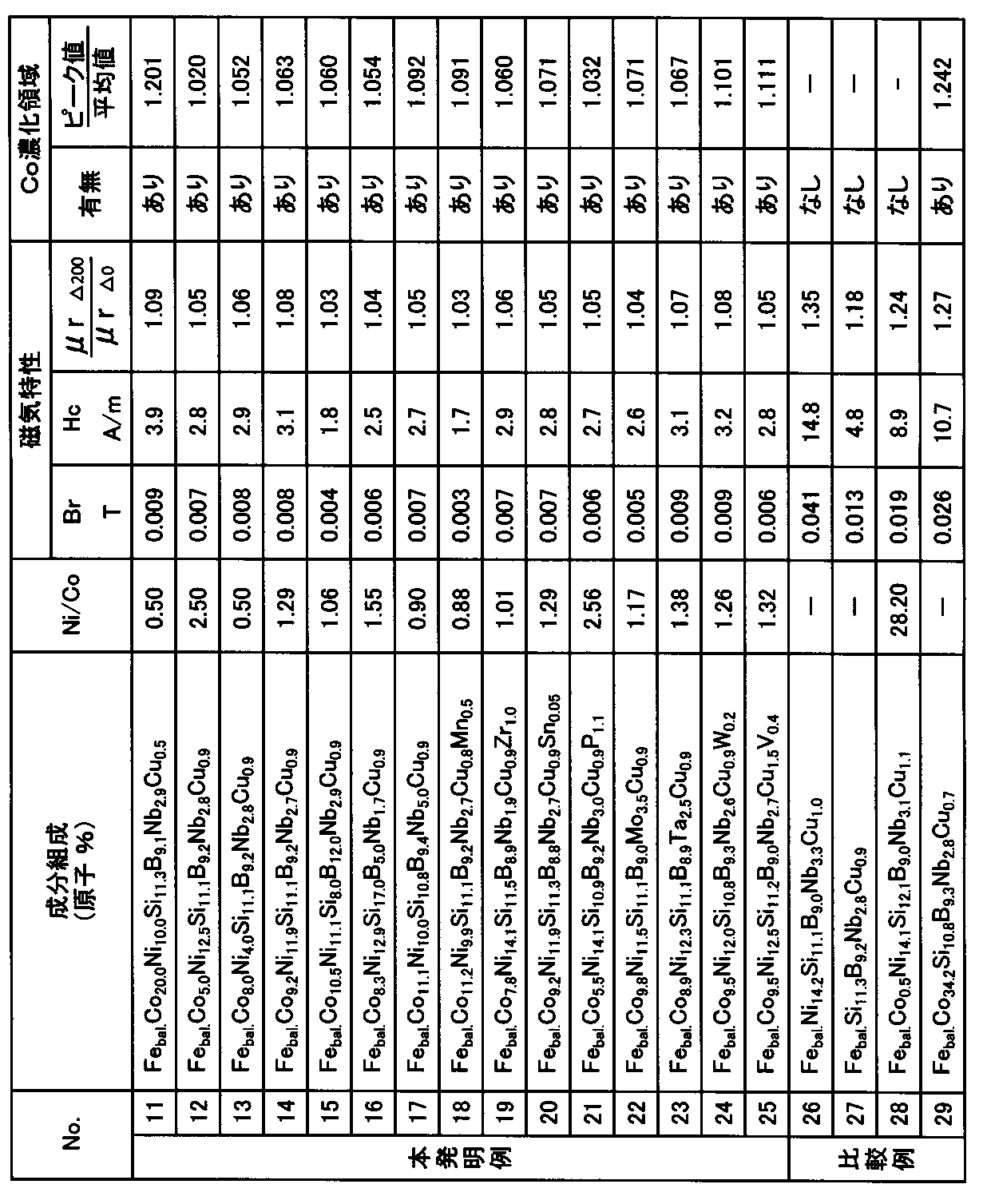
- Example 3 By the same method as in Example 1, an Fe-based alloy ribbon having a component composition (atomic%) shown in Table 2 having a width of 5 mm and an average thickness in the range of 18.0 ⁇ m to 20.3 ⁇ m was produced. Next, the produced ribbon was wound around an outer diameter of 19 mm and an inner diameter of 15 mm to produce a magnetic core (winding core). After the heat treatment by the heat treatment pattern shown in the same Figure 1 as in Example 1, and analysis by GDOES the free face side of the ribbon, DC B-H force - the blanking and incremental relative permeability mu r ⁇ measurements performed It was.
- the peak value of Co concentration is 1 to the average value of Co concentration measured in the range of 0.1 ⁇ m to 0.2 ⁇ m in depth from the surface of the ribbon. It was in the preferable range of 0.02 times or more and 1.20 times or less.
- the Fe-based soft magnetic alloy ribbon according to the present invention in which a Cu-enriched region exists immediately below the surface of the ribbon, and a Co-enriched region exists immediately below the Cu-enriched region, and It was confirmed that the magnetic core made of the ribbon has excellent soft magnetic properties.
Landscapes
- Chemical & Material Sciences (AREA)
- Engineering & Computer Science (AREA)
- Materials Engineering (AREA)
- Mechanical Engineering (AREA)
- Metallurgy (AREA)
- Organic Chemistry (AREA)
- Physics & Mathematics (AREA)
- Thermal Sciences (AREA)
- Crystallography & Structural Chemistry (AREA)
- Power Engineering (AREA)
- Dispersion Chemistry (AREA)
- Electromagnetism (AREA)
- Manufacturing & Machinery (AREA)
- Soft Magnetic Materials (AREA)
Abstract
Description
Co(コバルト)は、誘導磁気異方性を大きくする効果があり、低透磁率化に寄与するため、本発明のFe基軟磁性合金薄帯において必須の元素であり、5原子%以上20原子%以下とする。Co量が5原子%未満の場合、明確なCo濃化領域が生成されないことがある。また、Co量が少なすぎると、Coによる誘導磁気異方性を大きくする効果が低減し、透磁率が小さくならず、B-Hループの直線性も劣化することがある。Co量が20原子%を超える場合、薄帯の保磁力Hcが増加し、ヒステリシスが大きくなり、好ましくない特性を示すことがある。Coによる上述した効果は、Niによってある程度の代替が可能であるため、Coの一部をNiに置換することができる。 Co: 5 atomic% or more and 20 atomic% or less Co (cobalt) has an effect of increasing the induced magnetic anisotropy and contributes to a low magnetic permeability. Therefore, it is essential in the Fe-based soft magnetic alloy ribbon of the present invention. It is an element, and is 5 atomic% or more and 20 atomic% or less. When the amount of Co is less than 5 atomic%, a clear Co concentrated region may not be generated. If the amount of Co is too small, the effect of increasing the induced magnetic anisotropy due to Co is reduced, the magnetic permeability is not reduced, and the linearity of the BH loop may be deteriorated. When the Co content exceeds 20 atomic%, the coercive force Hc of the ribbon increases, and the hysteresis increases, which may exhibit undesirable characteristics. Since the effect described above by Co can be replaced to some extent by Ni, a part of Co can be replaced by Ni.
Cu(銅)は、本発明のFe基軟磁性合金薄帯において必須の元素であり、0.5原子%以上1.5原子%以下とする。Cu量が0.5原子%以上含まれていると、薄帯の作製時にCuクラスタが結晶化の際の不均一核生成サイトとして働くため、均一かつ微細な組織を有する薄帯が得られる。Cu量が0.5原子%未満の場合、Cuクラスタの数密度が不足し、薄帯の断面組織に見られる結晶粒組織が微細な結晶と少し粗大な結晶とが混在した組織となる。このような薄帯は、組織中の粒サイズおよび粒分布が不均一になることに起因して保磁力Hcが大きくなるため好ましくない。一方、Cu量が1.5原子%を超える場合、薄帯が著しく脆化して例えば薄帯の巻取が困難になるなど、薄帯を容易に製造できなくなるため好ましくない。薄帯の脆化を抑制して製造の容易化を図る観点からは、Cu量が0.7原子%以上1.2原子%以下であることが好ましい。 Cu: 0.5 atomic% or more and 1.5 atomic% or less Cu (copper) is an essential element in the Fe-based soft magnetic alloy ribbon of the present invention, and is 0.5 atomic% or more and 1.5 atomic% or less. To do. When the amount of Cu is contained at 0.5 atomic% or more, since the Cu cluster acts as a heterogeneous nucleation site at the time of crystallization at the time of producing the ribbon, a ribbon having a uniform and fine structure can be obtained. When the amount of Cu is less than 0.5 atomic%, the number density of Cu clusters is insufficient, and the crystal grain structure seen in the cross-sectional structure of the ribbon is a structure in which fine crystals and slightly coarse crystals are mixed. Such a ribbon is not preferable because the coercive force Hc is increased due to the non-uniform grain size and grain distribution in the structure. On the other hand, if the amount of Cu exceeds 1.5 atomic%, the ribbon becomes extremely brittle and, for example, it becomes difficult to wind the ribbon. From the viewpoint of facilitating production by suppressing the brittleness of the ribbon, the Cu content is preferably 0.7 atomic% or more and 1.2 atomic% or less.
薄帯は、所望する合金組成を有する素材を坩堝などで溶解して作製した溶湯を、坩堝などのノズルに設けたスリットから、20m/s~40m/sの周速で回転する銅合金製冷却ロ-ルの表面上に噴出させて急冷する方法により作製することができる。このような方法で作製された薄帯は、主相がアモルファス相の状態となり、必要に応じてスリット加工、切断加工、打抜き加工を行うことができる。薄帯の典型的な厚さ(板厚)は5μm~50μmであり、量産作製可能な幅は0.5mm~数100mmである。また、上述した方法で作製することができる薄帯を巻き回すことにより、磁心の形態に作製することができる。 Next, a processing method for obtaining a Fe-based soft magnetic alloy ribbon or a magnetic core made of the ribbon and having the predetermined soft magnetic properties will be described.
The ribbon is made of copper alloy that is melted by melting a material having the desired alloy composition in a crucible or the like, and is rotated at a peripheral speed of 20 m / s to 40 m / s from a slit provided in a nozzle of the crucible or the like. It can be produced by a method of jetting onto the surface of the roll and quenching. The ribbon produced by such a method is in a state where the main phase is in an amorphous phase, and can be slit, cut, and punched as necessary. The typical thickness (plate thickness) of the ribbon is 5 μm to 50 μm, and the width capable of mass production is 0.5 mm to several hundred mm. Moreover, it can produce in the form of a magnetic core by winding the ribbon which can be produced with the method mentioned above.
周速30m/sで回転している外径280mmのCu-Be合金ロ-ルを用いた単ロ-ル法により、原子%で、Coが11.1%、Niが10.2%、Siが11.0%、Bが9.1%、Nbが2.7%、Cuが0.8%、および残部がFeと不可避不純物からなる溶湯を用いて、幅5mm、平均厚さ20.2μmのFe基合金薄帯を作製した。この薄帯におけるNi/Coは約0.92である。次に、作製した薄帯を、外径19mm、内径15mmに巻き回して磁心(巻磁心)を作製した。作製した巻磁心の高さ方向(薄帯の幅方向)に300kA/mの磁界を印加しながら上述した第1熱処理過程(過程3aでは昇温速度3.6℃/min、過程3bでは保持温度430℃で保持時間30min)、第2熱処理過程(過程3cでは昇温速度2.2℃/min、過程3dでは保持温度560℃で保持時間30min)、および第3熱処理過程(過程3eでは降温速度2.7℃/minで降温目標温度170℃)を含み、降温目標温度に至った後の過程3fでは空冷を行う、図1に示す熱処理パターンによる窒素ガス雰囲気における熱処理を行った。なお、図1に示す熱処理では、280kA/mの磁界(H)を、合金薄帯の幅方向(磁心の高さ方向)に、降温過程で170℃に至るまでの全過程で印加した。 (Example 1)
By a single roll method using a Cu—Be alloy roll with an outer diameter of 280 mm rotating at a peripheral speed of 30 m / s, atomic percent, Co is 11.1%, Ni is 10.2%, Si Is 11.0%, B is 9.1%, Nb is 2.7%, Cu is 0.8%, and the balance is Fe and inevitable impurities, and the width is 5 mm and the average thickness is 20.2 μm. An Fe-based alloy ribbon was prepared. Ni / Co in this ribbon is about 0.92. Next, the produced ribbon was wound around an outer diameter of 19 mm and an inner diameter of 15 mm to produce a magnetic core (winding core). While applying a magnetic field of 300 kA / m in the height direction (in the width direction of the ribbon) of the produced wound magnetic core, the first heat treatment process described above (the heating rate is 3.6 ° C./min in the process 3a, and the holding temperature in the
実施例1と同様な方法により、原子%で、Coが3.1%、Niが10.1%、Siが10.9%、Bが8.9%、Nbが2.7%、Cuが0.8%、および残部がFeと不可避不純物からなる溶湯を用いて、幅25mm、平均厚さ20.0μmのFe基合金薄帯を作製した。この薄帯におけるNi/Coは約3.26である。次に、作製した薄帯を、実施例1と同様に、外径19mm、内径15mmに巻き回して磁心(巻磁心)を作製し、巻磁心の高さ方向(薄帯の幅方向)に300kA/mの磁界を印加しながら熱処理を行った。但し、実施例1と比較するために、図4に示す熱処理パターン(過程4aでは昇温速度3.6℃/min、過程4bでは保持温度560℃で保持時間5min、過程4cでは降温速度2.7℃/minで降温は室温まで)による窒素ガス雰囲気における熱処理を意図的に用いた。これは、上述した第1熱処理過程の第1温度域による保持過程および第2熱処理過程の昇温過程を有さない熱処理パターンであると、薄帯の内部に明確なCo濃化領域が生成されないからである。また、磁界(H)は280kA/mとし、合金薄帯の幅方向(磁心の高さ方向)に、図4に示す条件で熱処理の全過程で印加した。 (Comparative example)
In the same manner as in Example 1, in atomic%, Co is 3.1%, Ni is 10.1%, Si is 10.9%, B is 8.9%, Nb is 2.7%, Cu is An Fe-based alloy ribbon having a width of 25 mm and an average thickness of 20.0 μm was prepared using a molten metal consisting of 0.8% and the balance being Fe and inevitable impurities. The Ni / Co in this ribbon is about 3.26. Next, similarly to Example 1, the produced ribbon was wound around an outer diameter of 19 mm and an inner diameter of 15 mm to produce a magnetic core (winding core), and 300 kA in the height direction of the wound core (the width direction of the ribbon). Heat treatment was performed while applying a magnetic field of / m. However, for comparison with Example 1, the heat treatment pattern shown in FIG. 4 (temperature increase rate 3.6 ° C./min in step 4a, holding temperature 560 ° C. and holding time 5 min in
実施例1と同様な方法により、原子%で、Coが9.2%、Niが11.9%、Siが10.9%、Bが9.1%、Nbが2.7%、Cuが0.8%、および残部Feと不可避不純物からなる溶湯を用いて、幅10mm、平均厚さ18.3μmのFe基合金薄帯を作製した。この薄帯におけるNi/Coは約1.29である。次に、作製した薄帯を、外径24mm、内径18mmに巻き回して複数の磁心(巻磁心)を作製した。作製した巻磁心の高さ方向(薄帯の幅方向)に320kA/mの磁界を印加しながら上述した第1熱処理過程(表1に示す昇温速度HR1と保持温度Ta1および保持時間t1)、第2熱処理過程(表1に示す昇温速度HR2と保持温度Ta2および保持時間t2)、および第3熱処理過程(表1に示す降温速度CR3と降温目標温度190℃)を含み、降温目標温度に至った後の過程5aでは空冷を行う、図6に示す熱処理パターンによる窒素ガス雰囲気における熱処理を行った。また、磁界(H)は280kA/mとし、合金薄帯の幅方向(磁心の高さ方向)に、降温過程で170℃に至るまでの全過程で印加した。 (Example 2)
According to the same method as in Example 1, 9.2% Co, 11.9% Ni, 10.9% Si, 9.1% B, 9.1% B, 2.7% Nb, Cu An Fe-based alloy ribbon having a width of 10 mm and an average thickness of 18.3 μm was prepared using a molten metal composed of 0.8% and the balance Fe and inevitable impurities. The Ni / Co in this ribbon is about 1.29. Next, the produced ribbon was wound around an outer diameter of 24 mm and an inner diameter of 18 mm to produce a plurality of magnetic cores (winding cores). The above-described first heat treatment process (heating rate HR1, holding temperature Ta1, and holding time t1 shown in Table 1) while applying a magnetic field of 320 kA / m in the height direction (in the width direction of the ribbon) of the produced magnetic core, Including the second heat treatment process (temperature increase rate HR2 and holding temperature Ta2 and holding time t2 shown in Table 1) and the third heat treatment process (temperature reduction rate CR3 and temperature drop target temperature 190 ° C. shown in Table 1), In the

実施例1と同様な方法により、表2に示す成分組成(原子%)を有する幅5mm、平均厚さが18.0μm~20.3μmの範囲にあるFe基合金薄帯を作製した。次に、作製した薄帯を、外径19mm、内径15mmに巻き回して磁心(巻磁心)を作製した。実施例1と同様な図1で示す熱処理パターンによる熱処理を行った後に、薄帯の自由面側のGDOESによる分析と、直流B-Hカ-ブおよび増分比透磁率μr△の測定を行った。 (Example 3)
By the same method as in Example 1, an Fe-based alloy ribbon having a component composition (atomic%) shown in Table 2 having a width of 5 mm and an average thickness in the range of 18.0 μm to 20.3 μm was produced. Next, the produced ribbon was wound around an outer diameter of 19 mm and an inner diameter of 15 mm to produce a magnetic core (winding core). After the heat treatment by the heat treatment pattern shown in the same Figure 1 as in Example 1, and analysis by GDOES the free face side of the ribbon, DC B-H force - the blanking and incremental relative permeability mu r △ measurements performed It was.
1a:ピーク
1b:肩部
2:曲線
2a:ピーク
3a~3f:過程
4a~4c:過程
5a:過程
HR1:昇温速度(第1熱処理過程)
HR2:昇温速度(第2熱処理過程)
CR3:降温速度(第3熱処理過程)
Ta1:保持温度(第1熱処理過程)
Ta2:保持温度(第2熱処理過程)
t1:保持時間(第1熱処理過程)
t2:保持時間(第2熱処理過程)
1:
HR2: heating rate (second heat treatment process)
CR3: Temperature drop rate (third heat treatment process)
Ta1: Holding temperature (first heat treatment process)
Ta2: Holding temperature (second heat treatment process)
t1: Holding time (first heat treatment process)
t2: Holding time (second heat treatment process)
Claims (5)
- 5原子%以上20原子%以下のCoと、0.5原子%以上1.5原子%以下のCuを含むFe基軟磁性合金からなる薄帯であって、
前記薄帯の表面の直下にCu濃化領域が存在し、該Cu濃化領域の直下にCo濃化領域が存在する、Fe基軟磁性合金薄帯。 A ribbon made of an Fe-based soft magnetic alloy containing 5 atomic% to 20 atomic% Co and 0.5 atomic% to 1.5 atomic% Cu,
A Fe-based soft magnetic alloy ribbon in which a Cu-enriched region is present immediately below the surface of the ribbon, and a Co-enriched region is present immediately below the Cu-enriched region. - Co量をb原子%とし、Ni量をc原子%とするとき、0.5≦c/b≦2.5の関係を満足するように、15原子%以下のNiを含む、請求項1に記載のFe基軟磁性合金薄帯。 The Ni content is 15 atomic% or less so that the relationship of 0.5 ≦ c / b ≦ 2.5 is satisfied when the Co content is b atomic% and the Ni content is c atomic%. The Fe-based soft magnetic alloy ribbon described.
- 8原子%以上17原子%以下のSiと、5原子%以上12原子%以下のBと、1.7原子%以上5原子%以下のM(MはMo、Nb、Ta、W、およびVからなる群から選ばれた少なくとも1種の元素)とを含む、請求項1または2に記載のFe基軟磁性合金薄帯。 From 8 atomic% to 17 atomic% Si, 5 atomic% to 12 atomic% B, 1.7 atomic% to 5 atomic% M (M is Mo, Nb, Ta, W, and V) The Fe-based soft magnetic alloy ribbon according to claim 1 or 2, comprising at least one element selected from the group consisting of:
- 請求項1乃至3のいずれか1項に記載のFe基軟磁性合金薄帯を用いて構成される、磁心。 A magnetic core configured using the Fe-based soft magnetic alloy ribbon according to any one of claims 1 to 3.
- 半波正弦波交流電流の検出用カレントトランスに用いる、請求項4に記載の磁心。
The magnetic core according to claim 4, which is used for a current transformer for detecting a half-wave sine wave alternating current.
Priority Applications (5)
| Application Number | Priority Date | Filing Date | Title |
|---|---|---|---|
| US15/533,929 US10546674B2 (en) | 2014-12-22 | 2015-11-19 | Fe-based soft magnetic alloy ribbon and magnetic core comprising same |
| KR1020177016563A KR102282630B1 (en) | 2014-12-22 | 2015-11-19 | Fe-BASED SOFT MAGNETIC ALLOY RIBBON AND MAGNETIC CORE COMPRISING SAME |
| EP15872569.7A EP3239318B1 (en) | 2014-12-22 | 2015-11-19 | Fe-based soft magnetic alloy ribbon and magnetic core comprising same |
| CN201580069635.XA CN107109562B (en) | 2014-12-22 | 2015-11-19 | Fe based soft magnetic alloy thin band and the magnetic core for using it |
| JP2016566040A JP6669082B2 (en) | 2014-12-22 | 2015-11-19 | Fe-based soft magnetic alloy ribbon and magnetic core using the same |
Applications Claiming Priority (2)
| Application Number | Priority Date | Filing Date | Title |
|---|---|---|---|
| JP2014258562 | 2014-12-22 | ||
| JP2014-258562 | 2014-12-22 |
Publications (1)
| Publication Number | Publication Date |
|---|---|
| WO2016104000A1 true WO2016104000A1 (en) | 2016-06-30 |
Family
ID=56150033
Family Applications (1)
| Application Number | Title | Priority Date | Filing Date |
|---|---|---|---|
| PCT/JP2015/082491 WO2016104000A1 (en) | 2014-12-22 | 2015-11-19 | Fe-BASED SOFT MAGNETIC ALLOY RIBBON AND MAGNETIC CORE COMPRISING SAME |
Country Status (6)
| Country | Link |
|---|---|
| US (1) | US10546674B2 (en) |
| EP (1) | EP3239318B1 (en) |
| JP (1) | JP6669082B2 (en) |
| KR (1) | KR102282630B1 (en) |
| CN (1) | CN107109562B (en) |
| WO (1) | WO2016104000A1 (en) |
Cited By (4)
| Publication number | Priority date | Publication date | Assignee | Title |
|---|---|---|---|---|
| WO2019102667A1 (en) * | 2017-11-21 | 2019-05-31 | Tdk株式会社 | Soft magnetic alloy and magnetic component |
| US20190368013A1 (en) * | 2016-12-08 | 2019-12-05 | Carnegie Mellon University | Fe-Ni Nanocomposite Alloys |
| CN111033648A (en) * | 2017-08-18 | 2020-04-17 | 3M创新有限公司 | Magnetic film |
| JP7047959B1 (en) | 2021-03-31 | 2022-04-05 | Tdk株式会社 | Soft magnetic alloys and magnetic parts. |
Families Citing this family (10)
| Publication number | Priority date | Publication date | Assignee | Title |
|---|---|---|---|---|
| CN108130412A (en) * | 2017-12-25 | 2018-06-08 | 安徽迈德福新材料有限责任公司 | A kind of low temperature quickly heats the method for improving Electrodeposition Bath of Iron based alloy foil material magnetic property |
| JP6501005B1 (en) * | 2018-01-30 | 2019-04-17 | Tdk株式会社 | Soft magnetic alloys and magnetic parts |
| CN108597795B (en) * | 2018-04-13 | 2020-11-06 | 河南宝泉电力设备制造有限公司 | Amorphous dry-type transformer |
| US11936246B2 (en) * | 2018-11-05 | 2024-03-19 | Carnegie Mellon University | Axial flux motor |
| CN109599239A (en) * | 2018-12-11 | 2019-04-09 | 郑州大学 | It is a kind of perseverance magnetic conductivity iron base amorphous magnetically-soft alloy and application |
| DE102019110872A1 (en) * | 2019-04-26 | 2020-11-12 | Vacuumschmelze Gmbh & Co. Kg | Laminated core and method for producing a highly permeable soft magnetic alloy |
| CN110931237B (en) * | 2019-12-06 | 2021-07-02 | 武汉科技大学 | Preparation method of soft magnetic powder material with high resistivity and high mechanical strength |
| JP7400578B2 (en) * | 2020-03-24 | 2023-12-19 | Tdk株式会社 | Alloy ribbon and magnetic core |
| JP2022157029A (en) * | 2021-03-31 | 2022-10-14 | Tdk株式会社 | Soft magnetic alloy and magnetic component |
| JP2022157026A (en) * | 2021-03-31 | 2022-10-14 | Tdk株式会社 | Soft magnetic alloy and magnetic component |
Citations (7)
| Publication number | Priority date | Publication date | Assignee | Title |
|---|---|---|---|---|
| JP2000277357A (en) * | 1999-03-23 | 2000-10-06 | Hitachi Metals Ltd | Saturatable magnetic core and power supply apparatus using the same |
| WO2006064920A1 (en) * | 2004-12-17 | 2006-06-22 | Hitachi Metals, Ltd. | Magnetic core for current transformer, current transformer and watthour meter |
| JP2006525655A (en) * | 2003-04-02 | 2006-11-09 | バクームシュメルツェ ゲゼルシャフト ミット ベシュレンクテル ハフツング ウント コンパニ コマンディートゲゼルシャフト | Iron core and its manufacture and use |
| JP2008231462A (en) * | 2007-03-16 | 2008-10-02 | Hitachi Metals Ltd | Magnetic alloy, amorphous alloy strip and magnetic component |
| JP2009501273A (en) * | 2005-05-20 | 2009-01-15 | アンフイ・アロイ | Method for producing a strip of nanocrystalline material and apparatus for producing a wound core from said strip |
| JP2009263775A (en) * | 2008-03-31 | 2009-11-12 | Hitachi Metals Ltd | Thin strip of amorphous alloy, nanocrystal soft magnetic alloy, magnetic core, and method for producing the nanocrystal soft magnetic alloy |
| JP2010229466A (en) * | 2009-03-26 | 2010-10-14 | Hitachi Metals Ltd | Nano crystal soft magnetic alloy and magnetic core |
Family Cites Families (11)
| Publication number | Priority date | Publication date | Assignee | Title |
|---|---|---|---|---|
| JPS6479342A (en) | 1986-12-15 | 1989-03-24 | Hitachi Metals Ltd | Fe-base soft magnetic alloy and its production |
| US4881989A (en) | 1986-12-15 | 1989-11-21 | Hitachi Metals, Ltd. | Fe-base soft magnetic alloy and method of producing same |
| JPH01242755A (en) | 1988-03-23 | 1989-09-27 | Hitachi Metals Ltd | Fe-based magnetic alloy |
| US5800635A (en) * | 1995-06-15 | 1998-09-01 | Alliedsignal Inc. | Method of achieving a controlled step change in the magnetization loop of amorphous alloys |
| FR2756966B1 (en) * | 1996-12-11 | 1998-12-31 | Mecagis | METHOD FOR MANUFACTURING A MAGNETIC COMPONENT MADE OF SOFT MAGNETIC ALLOY IRON BASED HAVING A NANOCRYSTALLINE STRUCTURE |
| JP5316921B2 (en) * | 2007-03-16 | 2013-10-16 | 日立金属株式会社 | Fe-based soft magnetic alloy and magnetic component using the same |
| KR101162080B1 (en) * | 2007-03-22 | 2012-07-03 | 히타치 긴조쿠 가부시키가이샤 | Soft magnetic ribbon, magnetic core, magnetic part and process for producing soft magnetic ribbon |
| JP5445891B2 (en) | 2007-03-22 | 2014-03-19 | 日立金属株式会社 | Soft magnetic ribbon, magnetic core, and magnetic parts |
| JP5455041B2 (en) | 2007-04-25 | 2014-03-26 | 日立金属株式会社 | Soft magnetic ribbon, manufacturing method thereof, magnetic component, and amorphous ribbon |
| DE112010000836T5 (en) * | 2009-01-20 | 2012-12-06 | Hitachi Metals, Ltd. | A soft magnetic alloy ribbon and manufacturing method therefor, and a soft magnetic alloy ribbon magnetic device |
| KR102069927B1 (en) * | 2012-09-10 | 2020-01-23 | 히타치 긴조쿠 가부시키가이샤 | Ultrafine crystal alloy ribbon, fine crystal soft magnetic alloy ribbon, and magnetic parts using same |
-
2015
- 2015-11-19 JP JP2016566040A patent/JP6669082B2/en active Active
- 2015-11-19 CN CN201580069635.XA patent/CN107109562B/en active Active
- 2015-11-19 WO PCT/JP2015/082491 patent/WO2016104000A1/en active Application Filing
- 2015-11-19 EP EP15872569.7A patent/EP3239318B1/en active Active
- 2015-11-19 KR KR1020177016563A patent/KR102282630B1/en active IP Right Grant
- 2015-11-19 US US15/533,929 patent/US10546674B2/en active Active
Patent Citations (7)
| Publication number | Priority date | Publication date | Assignee | Title |
|---|---|---|---|---|
| JP2000277357A (en) * | 1999-03-23 | 2000-10-06 | Hitachi Metals Ltd | Saturatable magnetic core and power supply apparatus using the same |
| JP2006525655A (en) * | 2003-04-02 | 2006-11-09 | バクームシュメルツェ ゲゼルシャフト ミット ベシュレンクテル ハフツング ウント コンパニ コマンディートゲゼルシャフト | Iron core and its manufacture and use |
| WO2006064920A1 (en) * | 2004-12-17 | 2006-06-22 | Hitachi Metals, Ltd. | Magnetic core for current transformer, current transformer and watthour meter |
| JP2009501273A (en) * | 2005-05-20 | 2009-01-15 | アンフイ・アロイ | Method for producing a strip of nanocrystalline material and apparatus for producing a wound core from said strip |
| JP2008231462A (en) * | 2007-03-16 | 2008-10-02 | Hitachi Metals Ltd | Magnetic alloy, amorphous alloy strip and magnetic component |
| JP2009263775A (en) * | 2008-03-31 | 2009-11-12 | Hitachi Metals Ltd | Thin strip of amorphous alloy, nanocrystal soft magnetic alloy, magnetic core, and method for producing the nanocrystal soft magnetic alloy |
| JP2010229466A (en) * | 2009-03-26 | 2010-10-14 | Hitachi Metals Ltd | Nano crystal soft magnetic alloy and magnetic core |
Non-Patent Citations (1)
| Title |
|---|
| See also references of EP3239318A4 * |
Cited By (8)
| Publication number | Priority date | Publication date | Assignee | Title |
|---|---|---|---|---|
| US20190368013A1 (en) * | 2016-12-08 | 2019-12-05 | Carnegie Mellon University | Fe-Ni Nanocomposite Alloys |
| CN111033648A (en) * | 2017-08-18 | 2020-04-17 | 3M创新有限公司 | Magnetic film |
| WO2019102667A1 (en) * | 2017-11-21 | 2019-05-31 | Tdk株式会社 | Soft magnetic alloy and magnetic component |
| JP2019094532A (en) * | 2017-11-21 | 2019-06-20 | Tdk株式会社 | Soft magnetic alloy and magnetic component |
| US11508502B2 (en) | 2017-11-21 | 2022-11-22 | Tdk Corporation | Soft magnetic alloy and magnetic component |
| JP7047959B1 (en) | 2021-03-31 | 2022-04-05 | Tdk株式会社 | Soft magnetic alloys and magnetic parts. |
| JP2022157041A (en) * | 2021-03-31 | 2022-10-14 | Tdk株式会社 | Soft magnetic alloy and magnetic component |
| US11791077B2 (en) | 2021-03-31 | 2023-10-17 | Tdk Corporation | Soft magnetic alloy and magnetic component |
Also Published As
| Publication number | Publication date |
|---|---|
| KR102282630B1 (en) | 2021-07-27 |
| EP3239318A4 (en) | 2018-05-09 |
| JPWO2016104000A1 (en) | 2017-10-12 |
| US10546674B2 (en) | 2020-01-28 |
| JP6669082B2 (en) | 2020-03-18 |
| US20170323712A1 (en) | 2017-11-09 |
| CN107109562B (en) | 2019-07-23 |
| KR20170097041A (en) | 2017-08-25 |
| CN107109562A (en) | 2017-08-29 |
| EP3239318B1 (en) | 2021-06-02 |
| EP3239318A1 (en) | 2017-11-01 |
Similar Documents
| Publication | Publication Date | Title |
|---|---|---|
| WO2016104000A1 (en) | Fe-BASED SOFT MAGNETIC ALLOY RIBBON AND MAGNETIC CORE COMPRISING SAME | |
| JP7028290B2 (en) | Manufacturing method of nanocrystal alloy magnetic core | |
| EP2261385B1 (en) | Thin strip of amorphous alloy, nanocrystal soft magnetic alloy, and magnetic core | |
| JP5316920B2 (en) | Soft magnetic alloys, alloy ribbons with an amorphous phase as the main phase, and magnetic components | |
| JP5316921B2 (en) | Fe-based soft magnetic alloy and magnetic component using the same | |
| KR101162080B1 (en) | Soft magnetic ribbon, magnetic core, magnetic part and process for producing soft magnetic ribbon | |
| EP3242961B1 (en) | Nanocrystalline magnetic alloy and method of heat-treatment thereof | |
| JP5429613B2 (en) | Nanocrystalline soft magnetic alloys and magnetic cores | |
| US10347405B2 (en) | Alloy, magnet core and method for producing a strip from an alloy | |
| JP2014240516A (en) | Nanocrystal soft magnetic alloy and magnetic component using the same | |
| WO2019168159A1 (en) | Magnetic core, method of manufacturing same, and coil component | |
| JP2008231534A (en) | Soft magnetic thin band, magnetic core, and magnetic component | |
| JPWO2015046140A1 (en) | Method for producing Fe-based nanocrystalline alloy and method for producing Fe-based nanocrystalline alloy magnetic core | |
| EP2320436B1 (en) | Amorphous magnetic alloys, associated articles and methods | |
| JP2009293132A (en) | Soft magnetic thin band, magnetic core, magnetic component and method for producing soft magnetic thin band | |
| JP2008150637A (en) | Magnetic alloy, amorphous alloy ribbon and magnetic parts |
Legal Events
| Date | Code | Title | Description |
|---|---|---|---|
| 121 | Ep: the epo has been informed by wipo that ep was designated in this application |
Ref document number: 15872569 Country of ref document: EP Kind code of ref document: A1 |
|
| ENP | Entry into the national phase |
Ref document number: 2016566040 Country of ref document: JP Kind code of ref document: A |
|
| WWE | Wipo information: entry into national phase |
Ref document number: 15533929 Country of ref document: US |
|
| REEP | Request for entry into the european phase |
Ref document number: 2015872569 Country of ref document: EP |
|
| ENP | Entry into the national phase |
Ref document number: 20177016563 Country of ref document: KR Kind code of ref document: A |
|
| NENP | Non-entry into the national phase |
Ref country code: DE |