EP2320436B1 - Amorphous magnetic alloys, associated articles and methods - Google Patents
Amorphous magnetic alloys, associated articles and methods Download PDFInfo
- Publication number
- EP2320436B1 EP2320436B1 EP10173601A EP10173601A EP2320436B1 EP 2320436 B1 EP2320436 B1 EP 2320436B1 EP 10173601 A EP10173601 A EP 10173601A EP 10173601 A EP10173601 A EP 10173601A EP 2320436 B1 EP2320436 B1 EP 2320436B1
- Authority
- EP
- European Patent Office
- Prior art keywords
- alloy
- amorphous magnetic
- core
- magnetic alloy
- amorphous
- Prior art date
- Legal status (The legal status is an assumption and is not a legal conclusion. Google has not performed a legal analysis and makes no representation as to the accuracy of the status listed.)
- Active
Links
- 229910001004 magnetic alloy Inorganic materials 0.000 title claims description 47
- 238000000034 method Methods 0.000 title claims description 22
- 229910045601 alloy Inorganic materials 0.000 claims description 132
- 239000000956 alloy Substances 0.000 claims description 132
- XEEYBQQBJWHFJM-UHFFFAOYSA-N iron Substances [Fe] XEEYBQQBJWHFJM-UHFFFAOYSA-N 0.000 claims description 63
- 230000005291 magnetic effect Effects 0.000 claims description 46
- 238000002425 crystallisation Methods 0.000 claims description 32
- 230000008025 crystallization Effects 0.000 claims description 32
- 239000013526 supercooled liquid Substances 0.000 claims description 30
- 229910052742 iron Inorganic materials 0.000 claims description 15
- 238000012545 processing Methods 0.000 claims description 10
- 229910052710 silicon Inorganic materials 0.000 claims description 9
- 229910052799 carbon Inorganic materials 0.000 claims description 8
- 229910052796 boron Inorganic materials 0.000 claims description 6
- 229910017052 cobalt Inorganic materials 0.000 claims description 6
- 239000010941 cobalt Substances 0.000 claims description 6
- GUTLYIVDDKVIGB-UHFFFAOYSA-N cobalt atom Chemical compound [Co] GUTLYIVDDKVIGB-UHFFFAOYSA-N 0.000 claims description 6
- 229910052750 molybdenum Inorganic materials 0.000 claims description 6
- ZOXJGFHDIHLPTG-UHFFFAOYSA-N Boron Chemical compound [B] ZOXJGFHDIHLPTG-UHFFFAOYSA-N 0.000 claims description 5
- OKTJSMMVPCPJKN-UHFFFAOYSA-N Carbon Chemical compound [C] OKTJSMMVPCPJKN-UHFFFAOYSA-N 0.000 claims description 5
- ZOKXTWBITQBERF-UHFFFAOYSA-N Molybdenum Chemical compound [Mo] ZOKXTWBITQBERF-UHFFFAOYSA-N 0.000 claims description 5
- XUIMIQQOPSSXEZ-UHFFFAOYSA-N Silicon Chemical compound [Si] XUIMIQQOPSSXEZ-UHFFFAOYSA-N 0.000 claims description 5
- 238000010438 heat treatment Methods 0.000 claims description 5
- BHEPBYXIRTUNPN-UHFFFAOYSA-N hydridophosphorus(.) (triplet) Chemical compound [PH] BHEPBYXIRTUNPN-UHFFFAOYSA-N 0.000 claims description 5
- 239000011733 molybdenum Substances 0.000 claims description 5
- 239000000843 powder Substances 0.000 claims description 5
- 230000008569 process Effects 0.000 claims description 5
- 239000010703 silicon Substances 0.000 claims description 5
- 238000004519 manufacturing process Methods 0.000 claims description 4
- 230000000930 thermomechanical effect Effects 0.000 claims description 3
- 238000005019 vapor deposition process Methods 0.000 claims description 2
- 238000010297 mechanical methods and process Methods 0.000 claims 1
- 239000000203 mixture Substances 0.000 description 42
- 230000000052 comparative effect Effects 0.000 description 29
- 230000005415 magnetization Effects 0.000 description 28
- 239000011162 core material Substances 0.000 description 25
- 238000000137 annealing Methods 0.000 description 22
- 230000008859 change Effects 0.000 description 12
- 230000005294 ferromagnetic effect Effects 0.000 description 10
- 229910052752 metalloid Inorganic materials 0.000 description 9
- 230000006870 function Effects 0.000 description 8
- 229910052723 transition metal Inorganic materials 0.000 description 8
- 150000003624 transition metals Chemical class 0.000 description 8
- 238000007496 glass forming Methods 0.000 description 6
- 230000009477 glass transition Effects 0.000 description 6
- 239000005300 metallic glass Substances 0.000 description 5
- 229910052759 nickel Inorganic materials 0.000 description 5
- 238000005266 casting Methods 0.000 description 4
- 239000000696 magnetic material Substances 0.000 description 4
- 230000035699 permeability Effects 0.000 description 4
- 238000002441 X-ray diffraction Methods 0.000 description 3
- 229910000808 amorphous metal alloy Inorganic materials 0.000 description 3
- 238000001816 cooling Methods 0.000 description 3
- 239000010949 copper Substances 0.000 description 3
- 230000000694 effects Effects 0.000 description 3
- 238000002074 melt spinning Methods 0.000 description 3
- 229910052698 phosphorus Inorganic materials 0.000 description 3
- 238000006467 substitution reaction Methods 0.000 description 3
- RYGMFSIKBFXOCR-UHFFFAOYSA-N Copper Chemical compound [Cu] RYGMFSIKBFXOCR-UHFFFAOYSA-N 0.000 description 2
- 229910052802 copper Inorganic materials 0.000 description 2
- 230000000875 corresponding effect Effects 0.000 description 2
- 238000011161 development Methods 0.000 description 2
- 230000001747 exhibiting effect Effects 0.000 description 2
- 229910052735 hafnium Inorganic materials 0.000 description 2
- 239000000463 material Substances 0.000 description 2
- 239000011159 matrix material Substances 0.000 description 2
- 229910052758 niobium Inorganic materials 0.000 description 2
- 230000007704 transition Effects 0.000 description 2
- 229910052726 zirconium Inorganic materials 0.000 description 2
- 229910008423 Si—B Inorganic materials 0.000 description 1
- 241000276425 Xiphophorus maculatus Species 0.000 description 1
- 230000015572 biosynthetic process Effects 0.000 description 1
- 229910001567 cementite Inorganic materials 0.000 description 1
- 238000005056 compaction Methods 0.000 description 1
- 230000002596 correlated effect Effects 0.000 description 1
- 238000004512 die casting Methods 0.000 description 1
- 238000000605 extraction Methods 0.000 description 1
- 238000005242 forging Methods 0.000 description 1
- 239000011521 glass Substances 0.000 description 1
- 238000007731 hot pressing Methods 0.000 description 1
- 238000002347 injection Methods 0.000 description 1
- 239000007924 injection Substances 0.000 description 1
- 239000007788 liquid Substances 0.000 description 1
- 230000005389 magnetism Effects 0.000 description 1
- 238000002844 melting Methods 0.000 description 1
- 238000012544 monitoring process Methods 0.000 description 1
- 230000005855 radiation Effects 0.000 description 1
- 238000007712 rapid solidification Methods 0.000 description 1
- 238000011160 research Methods 0.000 description 1
- 238000005096 rolling process Methods 0.000 description 1
- 238000007711 solidification Methods 0.000 description 1
- 230000008023 solidification Effects 0.000 description 1
- 238000001228 spectrum Methods 0.000 description 1
- 239000000126 substance Substances 0.000 description 1
- 238000007669 thermal treatment Methods 0.000 description 1
- 230000009466 transformation Effects 0.000 description 1
Images


Classifications
-
- H—ELECTRICITY
- H01—ELECTRIC ELEMENTS
- H01F—MAGNETS; INDUCTANCES; TRANSFORMERS; SELECTION OF MATERIALS FOR THEIR MAGNETIC PROPERTIES
- H01F1/00—Magnets or magnetic bodies characterised by the magnetic materials therefor; Selection of materials for their magnetic properties
- H01F1/01—Magnets or magnetic bodies characterised by the magnetic materials therefor; Selection of materials for their magnetic properties of inorganic materials
- H01F1/03—Magnets or magnetic bodies characterised by the magnetic materials therefor; Selection of materials for their magnetic properties of inorganic materials characterised by their coercivity
- H01F1/12—Magnets or magnetic bodies characterised by the magnetic materials therefor; Selection of materials for their magnetic properties of inorganic materials characterised by their coercivity of soft-magnetic materials
- H01F1/14—Magnets or magnetic bodies characterised by the magnetic materials therefor; Selection of materials for their magnetic properties of inorganic materials characterised by their coercivity of soft-magnetic materials metals or alloys
- H01F1/147—Alloys characterised by their composition
- H01F1/153—Amorphous metallic alloys, e.g. glassy metals
- H01F1/15308—Amorphous metallic alloys, e.g. glassy metals based on Fe/Ni
-
- C—CHEMISTRY; METALLURGY
- C22—METALLURGY; FERROUS OR NON-FERROUS ALLOYS; TREATMENT OF ALLOYS OR NON-FERROUS METALS
- C22C—ALLOYS
- C22C45/00—Amorphous alloys
- C22C45/02—Amorphous alloys with iron as the major constituent
-
- H—ELECTRICITY
- H01—ELECTRIC ELEMENTS
- H01F—MAGNETS; INDUCTANCES; TRANSFORMERS; SELECTION OF MATERIALS FOR THEIR MAGNETIC PROPERTIES
- H01F41/00—Apparatus or processes specially adapted for manufacturing or assembling magnets, inductances or transformers; Apparatus or processes specially adapted for manufacturing materials characterised by their magnetic properties
- H01F41/02—Apparatus or processes specially adapted for manufacturing or assembling magnets, inductances or transformers; Apparatus or processes specially adapted for manufacturing materials characterised by their magnetic properties for manufacturing cores, coils, or magnets
- H01F41/0206—Manufacturing of magnetic cores by mechanical means
- H01F41/0213—Manufacturing of magnetic circuits made from strip(s) or ribbon(s)
- H01F41/0226—Manufacturing of magnetic circuits made from strip(s) or ribbon(s) from amorphous ribbons
-
- H—ELECTRICITY
- H01—ELECTRIC ELEMENTS
- H01F—MAGNETS; INDUCTANCES; TRANSFORMERS; SELECTION OF MATERIALS FOR THEIR MAGNETIC PROPERTIES
- H01F41/00—Apparatus or processes specially adapted for manufacturing or assembling magnets, inductances or transformers; Apparatus or processes specially adapted for manufacturing materials characterised by their magnetic properties
- H01F41/02—Apparatus or processes specially adapted for manufacturing or assembling magnets, inductances or transformers; Apparatus or processes specially adapted for manufacturing materials characterised by their magnetic properties for manufacturing cores, coils, or magnets
- H01F41/0206—Manufacturing of magnetic cores by mechanical means
- H01F41/0246—Manufacturing of magnetic circuits by moulding or by pressing powder
Definitions
- the invention relates generally to amorphous magnetic alloys. More particularly, the invention relates to amorphous magnetic alloys with high saturation magnetization and good thermal stability. The invention further relates to a magnetic component using such alloys and methods for making the magnetic component.
- Amorphous magnetic materials used for applications such as a core of a transformer, an inductor, etc., are typically an iron-based or cobalt-based amorphous alloy (also referred to as metallic glasses).
- cores for electric devices are arranged to form a stack or a coil. These stacks or coils are then cut into desired shapes to be employed in the core.
- Conventional metallic glasses include Fe-P-C-based metallic glasses first produced in the 1960s, (Fe, Co, Ni)-P-B-based alloy, (Fe, Co, Ni)-Si-B-based alloy, (Fe, Co, Ni)-(Zr, Hf, Nb)-based alloy, and (Fe, Co, Ni)-(Zr, Hf, Nb)-B-based alloy, produced in the 1970s.
- Most of these alloys are typically subjected to a rapid solidification process, that is, cooling the molten alloy at a sufficient cooling rate to a temperature below a glass transition temperature to suppress crystallization and produce an amorphous alloy.
- Amorphous alloys generally are prepared with small dimensions. However, the currently employed processes, such as melt spinning, often are subject to process limitations that prevent producing articles with desired dimensions.
- the amorphous magnetic alloys exhibit a glass transition at a temperature below a crystallization temperature, with a supercooled liquid region defined as the temperature range between the glass transition temperature and the crystallization temperature.
- the supercooled liquid region is generally considered to be related to the stability of the amorphous phase. Accordingly, the alloys having a wide supercooled liquid region are considered to be excellent in glass-forming ability, which has been further related to good thermal stability of the amorphous phase.
- Glass-forming ability is required to produce articles with desired shape and dimension from the amorphous magnetic alloy.
- the temperature interval ⁇ Tx of supercooled liquid is ⁇ 40K
- the diameter or the thickness is 1.5-4 mm
- the volumetric ratio of glassy phase is 100%
- the coercive force (Hc) is 1.5-2.1 A/m
- the saturation magnetization (Is) is 1.14 T-1.39 T
- the initial permeability at 1 KHz and 1A/m is 18,600-20,920.
- a bar-material or platy material manufactured by a copper mold casting method can be used as magnetic core material
- US patent 7,223,310 and US patent 7,357,844 disclosed a soft magnetic Fe-B-Si-based metallic glass alloy composition exhibiting clear glass transition, wide supercooled liquid region, and having high glass-forming ability and saturation magnetization.
- magnetic properties of such alloys are typically, not stable when the alloys are subjected to thermal processing. Thermal processing may be required to form the alloys into desired geometric shapes.
- One embodiment of the present invention provides an amorphous magnetic alloy having the general formula: (Fe 1-x Co x ) n Mo a P b B c C d Si e , wherein n is the atomic percent of iron and cobalt; x is the fraction of n; a, b, c, d and e are the atomic percent of molybdenum, phosphorous, boron, carbon and silicon respectively, wherein n, x, a, b, c, d and e are defined by following relationship:
- Another embodiment is an article comprising a magnetic component made of the amorphous magnetic alloy of the present invention.
- Yet another embodiment of the present invention provides a method of making an article.
- the method includes the steps of providing the amorphous magnetic alloy of the present invention and processing the alloy within a supercooled liquid region of the alloy.
- embodiments of the present invention include amorphous magnetic alloys (also referred as alloys or alloy compositions) having a good balance of magnetic properties, and thermal stability, and an article (magnetic component) made of such amorphous magnetic alloys.
- Approximating language may be applied to modify any quantitative representation that could permissibly vary without resulting in a change in the basic function to which it is related. Accordingly, a value modified by a term or terms, such as “about” or “substantially,” may not be limited to the precise value specified, and may include values that differ from the specified value. In at least some instances, the approximating language may correspond to the precision of an instrument for measuring the value.
- an amorphous magnetic alloy (metallic glass alloy) is defined as a magnetic material, where a continuous matrix phase has an amorphous nature, i.e. a disordered atomic-scale structure that does not have long-range crystallographic order.
- the amorphous magnetic alloy may also include crystalline phases within the amorphous matrix.
- crystallization temperature refers to the transition temperature at which the alloy changes, upon heating, from the amorphous state to the crystallization state.
- the alloy may have crystallization temperature in a range from about 400 degrees Celsius to about 550 degrees Celsius.
- glass-transition temperature refers to the transition temperature at which the alloy transforms from viscous liquid into an amorphous phase. This transformation usually occurs upon rapid cooling.
- an amorphous alloy transforms to a crystalline alloy when heated to a crystallization temperature.
- a change in magnetic properties such as coercivity and initial permeability of the amorphous magnetic alloy occurs, however, when the alloy is subjected to elevated temperatures considerably lower than the crystallization temperature.
- the thermal stability of the magnetic properties of the amorphous magnetic alloy is generally very poor.
- the alloys are stable for only a few minutes when heated to a temperature in the supercooled liquid region, resulting in large changes in properties such as coercivity, and thus allowing very little time for processing the alloy into a desired shape or form.
- coercivity refers to the magnetic field required to reduce the external magnetization of a ferromagnetic substance to zero. Furthermore, a change in coercivity from the as-rapidly solidified alloy value can be used as a measure of thermal stability of the amorphous magnetic alloys. The change in coercivity of an alloy is measured as a function of time at an elevated temperature to determine thermal stability of the alloy.
- thermal stability of the amorphous magnetic alloy refers to the ability of the alloy to retain its magnetic properties, such as coercivity, during exposure to elevated temperatures. This stability in magnetic characteristics is believed to be attributable to the ability of the amorphous phase to persist in the alloy during elevated temperature exposure. Conventionally, the thermal stability has been, generally, correlated to the supercooled liquid region for such alloys. However, according to an embodiment of the invention, while performing research on various amorphous magnetic alloy compositions, it was found that the size of the supercooled liquid region is not necessarily a good measure of the thermal stability. Instead, “time to crystallize” or “crystallization time” is a more important alloy property.
- crystallization time may be determined by isothermally annealing the alloys in the supercooled liquid region and monitoring the time required for the amorphous phase to begin to develop long-range order, which can be evidenced by a combination of X-ray diffraction spectrum changes, onset of brittleness and increase in the coercivity of the alloy.
- the alloy composition comprises a selection of ferromagnetic transition metals (Fe and Co), non-magnetic transition metals (Mo) and metalloid elements (B, C, P and Si).
- the metalloid elements tend to promote the formation of an amorphous phase and are chosen to increase the number of equilibrium phases.
- the thermodynamic competition between the equilibrium crystalline phases slows down the crystallization kinetics, allowing the amorphous phase to be maintained during solidification.
- a consequence of the presence of the metalloid elements is that the saturation magnetization of the alloy is reduced.
- glass-forming ability of the alloy can be increased at the cost of magnetic properties.
- Table 1 shows the respective alloy compositions of inventive alloys 1 to 13 and comparative alloys 1 to 10, and their respective saturation magnetization (M s ), coercivity (H c ), supercooled liquid region ( ⁇ T x ) and crystallization time or time to crystallize (t). Ribbon samples of each composition were investigated for their magnetic properties and thermal behavior. A method of making ribbon samples is discussed below. X-ray diffraction measurements were employed to distinguish the amorphous and crystalline state of the alloy.
- these samples were annealed within the supercooled liquid region at a temperature 20 degree Celsius below the crystallization temperature of the corresponding alloy. Coercivity of each sample was measured as a function of annealing time at this annealing temperature.
- the alloys have a coercivity value the same or lower than the as-cast coercivity value for times in excess of 10 minutes.
- the ferromagnetic transition metals such as Fe, Co, and Ni, provide saturation magnetization and soft magnetic characteristics.
- the alloy composition includes an amount of the ferromagnetic transition metals (Fe and Co) (n) ranging from about 76 to about 85 atomic percent.
- the element Co is substituted for a fraction of Fe depending on desired saturation magnetization and thermal stability.
- a preferred ratio of Fe and Co to maximize saturation magnetization and thermal stability may, also, depend on the presence and concentration of the metalloid elements.
- the fraction of the element Co (x) in the ferromagnetic transition metal component is in a range from about 0.05 to about 0.50 of ferromagnetic elements. Moreover, the presence of Co in an amount greater than a fraction of about 0.10 of ferromagnetic elements substantially increases the thermal stability of the amorphous phase of the alloy. In one embodiment, depending on the ratios of the metalloid elements, the saturation magnetization of the alloy is a maximum for Co fraction (x) ranging from about 0.15 to about 0.35 of ferromagnetic elements.
- the non-magnetic transition metal, Mo is added as a glass former due to its relatively large atomic diameter.
- Mo may be substituted for both Fe and Si.
- the amount of Mo, (a) may be substituted in a range from about 0 to about 4 atomic percent.
- the amount of Mo may be substituted in a range from about 0 to about 2 atomic percent, and in particular embodiments, to about 1 atomic percent.
- inventive alloy 9 shows a good balance of magnetic properties and thermal stability as shown in Table 1. The inventive alloy 9 is stable for about 15 minutes as illustrated in graph of FIG. 2 .
- the ratios of the metalloid elements may be adjusted to optimize alloy properties, such as glass-forming ability and thermal stability. Substitution of B for C tends to increase the saturation magnetization (M s ), but tends to reduce the thermal stability. The significant effect of B is evidenced by change in coercivity with annealing time of the inventive alloys 5, 6, and 7 as shown in FIG. 2 .
- the alloy may or may not include B.
- the amount of B (c) is less than the amount of C (d).
- the addition of P tended to have a significant effect on the thermal stability of the alloy.
- the alloys with higher amount of P (b) are thermally stable for longer times.
- the addition of P promotes a large number of stable and metastable phases, which tend to retard the crystallization kinetics.
- the amount of P (b) is at least about 10 atomic percent.
- the amount of P (b) and amount of C (d) can be selected to provide a desired level of the metalloid elements.
- the combined amount of P and C, (b+d) is at least about 15 atomic percent.
- (b+d) varies from about 15 atomic percent to about 20 atomic percent.
- the ratio of the amount of P and the amount of C (b:d) can be helpful to balance magnetic properties and thermal stability.
- the ratio (b:d) varies from about 8:12 to about 12:8.
- the ratio (b:d) is 1:1.
- the inventive alloys 1, 2, 3, 4 having the ratio b:d of 10:10 exhibit a good balance of saturation magnetization and thermal stability as shown in Table 1 and FIG.
- comparative alloy 3 having the ratio of (b:d) of 4:14 showed lower saturation magnetization.
- a graph in FIG. 3 shows a comparative study of inventive alloy 3 and comparative alloy 3 with respect to their thermal stability. It is clear from the graph that change in coercivity of the comparative alloy 3 is relatively large on annealing even for 10 minutes and very large on annealing for about 15 minutes.
- the amount of Si (e) varies from about 0.1 to about 2.0 atomic percent. In certain embodiments, the amount of Si (e) varies from about 1.0 to about 1.5 atomic percent. Increasing the amount of Si (e) beyond about 1.5 atomic percent, the alloy shows further increase in the thermal stability but a decrease in the saturation magnetization as shown by inventive alloys 10 and 11 in Table 1.
- FIG. 5 illustrates a graph showing change in coercivity with annealing time of alloys ((Fe 0.8 Co 0.2 ) 80-e C 10 P 10 Si e ) with increasing amount of Si (e).
- comparative alloys 3 and 8 showed reduced thermal stability.
- the comparative alloy 3 is stable for less than about 10 minutes as evident from Table 1 and FIG. 3 .
- the amorphous magnetic alloys of the compositions described above have a very good balance of magnetic and thermal properties. Furthermore, it was observed from the above-discussed studies that crystallization kinetics is not coupled to the range of the supercooled liquid region of the alloy. For example, some of the comparative alloys have substantially similar large supercooled liquid regions ( ⁇ T x ) relative to those of the inventive alloys, while having crystallization times less than 10 minutes and thus exhibiting poor thermal stability as compared to the inventive alloys. On the other hand, some of the inventive alloys having a narrow supercooled liquid region exhibit very good thermal stability with increased crystallization time, relative to comparative alloys.
- Embodiments of the present invention provide an article including a magnetic component.
- the magnetic component is made of an amorphous magnetic alloy having the composition as described above.
- the amorphous magnetic alloy may be very suitable for magnetic components, such as a magnetic core, a magnetic head, a magnetic shield, an electromagnet, and the like.
- the magnetic component is a magnetic core.
- Various forms of the core include a ribbon or tape-wound core, a wire-wound core, or a powder core.
- a tape-wound core may be formed of an amorphous magnetic alloy ribbon or tape wrapped concentrically around a preform, such as a cylindrical bobbin.
- a wire wound core is formed of amorphous magnetic alloy wire wrapped around a preform.
- magnetic core refers to a piece of magnetic material with a high permeability used to confine and guide magnetic fields in electrical and electromechanical devices such as electromagnets, transformers, electric motors and inductors.
- the high permeability relative to the surrounding air, causes the magnetic field lines to be concentrated in the magnetic core.
- the magnetic field is, often, created by a coil around a core that carries a current.
- the presence of the core can increase the magnetic field of a coil by a factor of several thousand over what it would be without the core.
- each form of the magnetic component may be constructed in a variety of shapes selected from the group consisting of a toroidal core, a C-core, an E-core, a D-core, a pot core, a ring core, a planar core or a bar core.
- These magnetic components can be employed in a transformer, an inductor, a filter, a choke, a solenoid, a generator, a motor or a fluxgate.
- a method of making an article includes the steps of providing the amorphous magnetic alloy having the composition described previously, and processing the alloy within a supercooled liquid region of the alloy.
- the processing of the alloy may further include thermal treatment.
- providing the amorphous magnetic alloy includes forming the alloy by using a casting process.
- casting process include, but are not limited to, melt-spinning, melt extraction, injection casting, and die-casting.
- the amorphous magnetic alloy takes some time to crystallize. This "crystallization time” provides a time for processing the alloy to form desired geometrical shapes before magnetic properties of the alloy are degraded.
- thermo-mechanical techniques include forging, extruding, rolling, hot pressing, swaging, drawing and powder compaction.
- Amorphous magnetic alloy samples were made by initially producing ingots of about 10 g by arc-melting a mixture of pre-alloyed Fe 3 P, Fe 3 B, Fe 3 C together with the other elements - Co, Mo and Si, in their elemental form under a Ti-gettered Ar atmosphere in a water-cooled copper crucible. Ribbon samples of different compositions were made by the melt-spinning technique under a partial He atmosphere. The tangential wheel speed was approximately 40 m/s and produced ribbons of approximately 20 ⁇ m in thickness.
- the amorphous nature of the melt-spun ribbons was confirmed by X-ray diffraction with Cu K ⁇ radiation.
- Thermal behavior of the samples was investigated in a differential scanning calorimeter at a constant heating rate of 10°C/s. Magnetic properties were characterized using a vibrating sample magnetometer (VSM). The VSM had a maximum applied field of 1.8T and field resolution of 0.796 A/m(0.01 Oe). Typically, a magnetic field of -0.03 T was sufficient to reach saturation magnetization for the samples investigated.
- Thermal stability was investigated by determining crystallization time for each sample by isothermally annealing the alloys within their respective supercooled liquid region, about 20 degrees Celsius below the measured crystallization temperature (T x ) for each composition. Annealing temperatures for the compositions are represented in the corresponding graphs in parentheses.
- the saturation magnetization of each of the alloy compositions is shown in Table 1. These alloys were annealed for about 30 minutes at a temperature within their respective supercooled liquid region, about 20 degrees Celsius below the measured crystallization temperature (T x ) for each composition.
- T x crystallization temperature
- Amorphous magnetic alloy according to the present invention having the composition (Fe 0.8 Co 0.2 ) 78 Mo 1 B 3 C 7 P 10 Si 1 was produced by the above described procedure.
- the saturation magnetization the alloy composition is shown in Table 1.
- This composition was annealed at about 430 degrees Celsius for about 20 minutes.
- the change in coercivity of the alloy during annealing is shown in FIG. 2 .
- the alloy composition was found to be thermally stable for about 15 minutes at 430 degrees Celsius which is within the supercooled liquid region, about 20 degrees Celsius below the measured crystallization temperature (T x ) for this amorphous magnetic alloy composition.
- the saturation magnetization of each of the alloy compositions is shown in Table 1.
- These alloys were annealed at a temperature within their respective supercooled liquid region about 20 degrees below the measured crystallization temperature (T x ) for each composition.
- T x The change in coercivity of the alloys during annealing is shown in FIG. 2 .
- the saturation magnetization of each of the alloy compositions is shown in Table 1.
- These alloys were annealed at a temperature within their respective supercooled liquid region about 20 degrees below the measured crystallization temperature (T x ) for each composition.
- the change in coercivity of the alloys during annealing is shown in FIG. 5 .
- These alloy compositions were found to be thermally stable for more than about 25 minutes.
- the amorphous magnetic alloys according to the present invention having the compositions (Fe 0.8 Co 0.2 ) 78.5 C 10 P 10 Si 1.5 and (Fe 0.75 Co 0.25 ) 78.5 C 10 P 10 Si 1.5 were produced by the above-described procedure.
- the saturation magnetization of each of the alloy composition is shown in Table 1. These alloys were annealed at a temperature within their respective supercooled liquid region about 20 degrees below the measured crystallization temperature (T x ) for each composition. These alloy compositions were found to be thermally stable for more than about 20 minutes.
Description
- The invention relates generally to amorphous magnetic alloys. More particularly, the invention relates to amorphous magnetic alloys with high saturation magnetization and good thermal stability. The invention further relates to a magnetic component using such alloys and methods for making the magnetic component.
- Development of amorphous soft magnetic materials is important to the development of high performance power electronic devices. Amorphous magnetic materials used for applications such as a core of a transformer, an inductor, etc., are typically an iron-based or cobalt-based amorphous alloy (also referred to as metallic glasses). Typically, cores for electric devices are arranged to form a stack or a coil. These stacks or coils are then cut into desired shapes to be employed in the core.
- Conventional metallic glasses include Fe-P-C-based metallic glasses first produced in the 1960s, (Fe, Co, Ni)-P-B-based alloy, (Fe, Co, Ni)-Si-B-based alloy, (Fe, Co, Ni)-(Zr, Hf, Nb)-based alloy, and (Fe, Co, Ni)-(Zr, Hf, Nb)-B-based alloy, produced in the 1970s. Most of these alloys are typically subjected to a rapid solidification process, that is, cooling the molten alloy at a sufficient cooling rate to a temperature below a glass transition temperature to suppress crystallization and produce an amorphous alloy. Amorphous alloys generally are prepared with small dimensions. However, the currently employed processes, such as melt spinning, often are subject to process limitations that prevent producing articles with desired dimensions.
- The amorphous magnetic alloys exhibit a glass transition at a temperature below a crystallization temperature, with a supercooled liquid region defined as the temperature range between the glass transition temperature and the crystallization temperature. The supercooled liquid region is generally considered to be related to the stability of the amorphous phase. Accordingly, the alloys having a wide supercooled liquid region are considered to be excellent in glass-forming ability, which has been further related to good thermal stability of the amorphous phase.
- Glass-forming ability is required to produce articles with desired shape and dimension from the amorphous magnetic alloy.
-
JP 2008 024985A -
US patent 7,223,310 andUS patent 7,357,844 disclosed a soft magnetic Fe-B-Si-based metallic glass alloy composition exhibiting clear glass transition, wide supercooled liquid region, and having high glass-forming ability and saturation magnetization. However, magnetic properties of such alloys are typically, not stable when the alloys are subjected to thermal processing. Thermal processing may be required to form the alloys into desired geometric shapes. - Thus, there is a need to provide an improved amorphous magnetic alloy having good glass-forming ability and good thermal stability while maintaining the desired balance of magnetic properties. There is a further need for an article having a magnetic component with improved properties as compared to conventional magnetic components. Moreover, there is a need for methods to produce such amorphous magnetic alloys and articles of desired dimensions.
- One embodiment of the present invention provides an amorphous magnetic alloy having the general formula: (Fe1-x Cox)n Moa Pb Bc Cd Sie, wherein n is the atomic percent of iron and cobalt; x is the fraction of n; a, b, c, d and e are the atomic percent of molybdenum, phosphorous, boron, carbon and silicon respectively, wherein n, x, a, b, c, d and e are defined by following relationship:
- 76 ≤ n ≤ 85
- 0.05 < x ≤ 0.50;
- 0≤a≤4; b ≥ 10;
- 0 ≤ c <d; and
- 0.1 ≤e≤2.
- Another embodiment is an article comprising a magnetic component made of the amorphous magnetic alloy of the present invention.
- Yet another embodiment of the present invention provides a method of making an article. The method includes the steps of providing the amorphous magnetic alloy of the present invention and processing the alloy within a supercooled liquid region of the alloy.
-
-
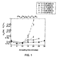
FIG. 1 shows comparative graphs of saturation magnetization as a function of annealing time forinventive alloys 1, 2, 3, 4 andcomparative alloys 1 and 2 as per Table 1, according to an embodiment of the present invention. -
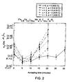
FIG. 2 shows comparative graphs of saturation magnetization as a function of annealing time forinventive alloys 3, 5, 6, 7 and 9 as per Table 1, according to another embodiment of the present invention. -
FIG. 3 shows comparative graphs of saturation magnetization as a function of annealing time for inventive alloy 3 and comparative alloy 3 as per Table 1, according to yet another embodiment of the present invention. -
FIG. 4 shows comparative graphs of saturation magnetization as a function of annealing time for inventive alloy 3 andcomparative alloy 4 and 5 as per Table 1, according to yet another embodiment of the present invention. -
FIG. 5 shows comparative graphs of saturation magnetization as a function of annealing time forinventive alloys 2, 10 and 11 as per Table 1, according to yet another embodiment of the present invention. - As discussed in detail below, embodiments of the present invention include amorphous magnetic alloys (also referred as alloys or alloy compositions) having a good balance of magnetic properties, and thermal stability, and an article (magnetic component) made of such amorphous magnetic alloys.
- In the following specification and the claims that follow, the singular forms "a," "an," and "the" include plural referents unless the context clearly dictates otherwise.
- Approximating language, as used herein throughout the specification and claims, may be applied to modify any quantitative representation that could permissibly vary without resulting in a change in the basic function to which it is related. Accordingly, a value modified by a term or terms, such as "about" or "substantially," may not be limited to the precise value specified, and may include values that differ from the specified value. In at least some instances, the approximating language may correspond to the precision of an instrument for measuring the value.
- For purposes of this invention, an amorphous magnetic alloy (metallic glass alloy) is defined as a magnetic material, where a continuous matrix phase has an amorphous nature, i.e. a disordered atomic-scale structure that does not have long-range crystallographic order. The amorphous magnetic alloy may also include crystalline phases within the amorphous matrix.
- As used herein, the term "crystallization temperature" (Tx) refers to the transition temperature at which the alloy changes, upon heating, from the amorphous state to the crystallization state. The alloy, according to one embodiment of the invention, may have crystallization temperature in a range from about 400 degrees Celsius to about 550 degrees Celsius.
- As used herein, the term "glass-transition temperature" (Tg) refers to the transition temperature at which the alloy transforms from viscous liquid into an amorphous phase. This transformation usually occurs upon rapid cooling.
- The term "supercooled liquid region" as used herein refers to a temperature interval (ΔTx) defined by the difference between the crystallization temperature (Tx) and the glass transition temperature (Tg): (ΔTx = Tx ~ Tg).
- As known by those skilled in the art, an amorphous alloy transforms to a crystalline alloy when heated to a crystallization temperature. A change in magnetic properties such as coercivity and initial permeability of the amorphous magnetic alloy occurs, however, when the alloy is subjected to elevated temperatures considerably lower than the crystallization temperature. In other words, the thermal stability of the magnetic properties of the amorphous magnetic alloy is generally very poor. Usually, the alloys are stable for only a few minutes when heated to a temperature in the supercooled liquid region, resulting in large changes in properties such as coercivity, and thus allowing very little time for processing the alloy into a desired shape or form.
- As used herein, the term "coercivity" refers to the magnetic field required to reduce the external magnetization of a ferromagnetic substance to zero. Furthermore, a change in coercivity from the as-rapidly solidified alloy value can be used as a measure of thermal stability of the amorphous magnetic alloys. The change in coercivity of an alloy is measured as a function of time at an elevated temperature to determine thermal stability of the alloy.
- As used herein, the term "thermal stability" of the amorphous magnetic alloy refers to the ability of the alloy to retain its magnetic properties, such as coercivity, during exposure to elevated temperatures. This stability in magnetic characteristics is believed to be attributable to the ability of the amorphous phase to persist in the alloy during elevated temperature exposure. Conventionally, the thermal stability has been, generally, correlated to the supercooled liquid region for such alloys. However, according to an embodiment of the invention, while performing research on various amorphous magnetic alloy compositions, it was found that the size of the supercooled liquid region is not necessarily a good measure of the thermal stability. Instead, "time to crystallize" or "crystallization time" is a more important alloy property.
- As used herein the term "crystallization time" may be determined by isothermally annealing the alloys in the supercooled liquid region and monitoring the time required for the amorphous phase to begin to develop long-range order, which can be evidenced by a combination of X-ray diffraction spectrum changes, onset of brittleness and increase in the coercivity of the alloy.
- Embodiments of the present invention provide an amorphous magnetic alloy expressed by the general formula:
(Fe1-x Cox)n Moa Pb Bc Cd Sie,
wherein n+a+b+c+d+e = 100; n is the atomic percent of iron and cobalt; x is the fraction of n; a, b, c, d and e are the atomic percent of molybdenum, phosphorous, boron, carbon and silicon respectively, wherein n, x, a, b, c, d and e are defined by following relationship: - 76≤n≤85
- 0.05 <x≤ 0.50;
- 0≤a≤4; b≥ 10;
- 0≤c<d; and
- 0,1≤e≤ 2
- In the above alloy of the present invention, the alloy composition comprises a selection of ferromagnetic transition metals (Fe and Co), non-magnetic transition metals (Mo) and metalloid elements (B, C, P and Si).
- The metalloid elements tend to promote the formation of an amorphous phase and are chosen to increase the number of equilibrium phases. The thermodynamic competition between the equilibrium crystalline phases slows down the crystallization kinetics, allowing the amorphous phase to be maintained during solidification. However, a consequence of the presence of the metalloid elements is that the saturation magnetization of the alloy is reduced. Thus, glass-forming ability of the alloy can be increased at the cost of magnetic properties.
- Table 1 shows the respective alloy compositions of
inventive alloys 1 to 13 andcomparative alloys 1 to 10, and their respective saturation magnetization (Ms), coercivity (Hc), supercooled liquid region (ΔTx) and crystallization time or time to crystallize (t). Ribbon samples of each composition were investigated for their magnetic properties and thermal behavior. A method of making ribbon samples is discussed below. X-ray diffraction measurements were employed to distinguish the amorphous and crystalline state of the alloy. - Furthermore, these samples were annealed within the supercooled liquid region at a
temperature 20 degree Celsius below the crystallization temperature of the corresponding alloy. Coercivity of each sample was measured as a function of annealing time at this annealing temperature. In a preferred embodiment, the alloys have a coercivity value the same or lower than the as-cast coercivity value for times in excess of 10 minutes. - In the alloy compositions, the ferromagnetic transition metals such as Fe, Co, and Ni, provide saturation magnetization and soft magnetic characteristics. The alloy composition includes an amount of the ferromagnetic transition metals (Fe and Co) (n) ranging from about 76 to about 85 atomic percent. The element Co is substituted for a fraction of Fe depending on desired saturation magnetization and thermal stability. A preferred ratio of Fe and Co to maximize saturation magnetization and thermal stability may, also, depend on the presence and concentration of the metalloid elements.
- The fraction of the element Co (x) in the ferromagnetic transition metal component is in a range from about 0.05 to about 0.50 of ferromagnetic elements. Moreover, the presence of Co in an amount greater than a fraction of about 0.10 of ferromagnetic elements substantially increases the thermal stability of the amorphous phase of the alloy. In one embodiment, depending on the ratios of the metalloid elements, the saturation magnetization of the alloy is a maximum for Co fraction (x) ranging from about 0.15 to about 0.35 of ferromagnetic elements.
- Furthermore, it was observed that Co substitution lowers the crystallization temperature (Tx), while increasing the crystallization time, in one embodiment. For example,
comparative alloy 1 without Co has ΔTx = 20°C and the crystallization time is less than 10 minutes, while substituting Fe with Co ininventive alloys 1, 2, 3, 4 showed increased ΔTx and crystallization time, as evident in Table 1. These observations are further evident by a graph shown asFIG.1 . The graph shows change in coercivity of the alloy (Fe1-xCox)79C10P10Si1 for x = 0, 0.05, 0.1, 0.15, 0.2 and 0.25 with annealing time. - According to one embodiment of the invention, the non-magnetic transition metal, Mo, is added as a glass former due to its relatively large atomic diameter. Mo may be substituted for both Fe and Si. In one embodiment, the amount of Mo, (a), may be substituted in a range from about 0 to about 4 atomic percent. In certain embodiments, the amount of Mo may be substituted in a range from about 0 to about 2 atomic percent, and in particular embodiments, to about 1 atomic percent. For example, inventive alloy 9 shows a good balance of magnetic properties and thermal stability as shown in Table 1. The inventive alloy 9 is stable for about 15 minutes as illustrated in graph of
FIG. 2 . - The ratios of the metalloid elements (B, P, C and Si) may be adjusted to optimize alloy properties, such as glass-forming ability and thermal stability. Substitution of B for C tends to increase the saturation magnetization (Ms), but tends to reduce the thermal stability. The significant effect of B is evidenced by change in coercivity with annealing time of the
inventive alloys 5, 6, and 7 as shown inFIG. 2 . In one embodiment, the alloy may or may not include B. In another embodiment, the amount of B (c) is less than the amount of C (d). - It was observed that the addition of P tended to have a significant effect on the thermal stability of the alloy. The alloys with higher amount of P (b) are thermally stable for longer times. The addition of P promotes a large number of stable and metastable phases, which tend to retard the crystallization kinetics. In one embodiment, the amount of P (b) is at least about 10 atomic percent.
- The amount of P (b) and amount of C (d) can be selected to provide a desired level of the metalloid elements. In one embodiment, the combined amount of P and C, (b+d), is at least about 15 atomic percent. In another embodiment, (b+d) varies from about 15 atomic percent to about 20 atomic percent. Furthermore, the ratio of the amount of P and the amount of C (b:d) can be helpful to balance magnetic properties and thermal stability. In one embodiment, the ratio (b:d) varies from about 8:12 to about 12:8. In a preferred embodiment, the ratio (b:d) is 1:1. For example, the
inventive alloys 1, 2, 3, 4 having the ratio b:d of 10:10, exhibit a good balance of saturation magnetization and thermal stability as shown in Table 1 andFIG. 1 . In contrast, comparative alloy 3 having the ratio of (b:d) of 4:14 showed lower saturation magnetization. Furthermore, a graph inFIG. 3 shows a comparative study of inventive alloy 3 and comparative alloy 3 with respect to their thermal stability. It is clear from the graph that change in coercivity of the comparative alloy 3 is relatively large on annealing even for 10 minutes and very large on annealing for about 15 minutes. - In addition, the presence or the absence of Si may affect the thermal stability. Removing Si or substituting ferromagnetic transition metals with any other metalloid elements, for example B, resulted in an increase in saturation magnetization but a decrease in thermal stability as shown in Table 1. Effects of absence and presence of Si on thermal stability are further evidenced by a graph shown in
FIG.4 . It is clear from the graph thatcomparative alloys 4 and 5, the alloys for e = 0, that is without Si, are not thermally stable. However, substitution of Si for the ferromagnetic transition metals or for the metalloid elements in small quantity, for example as in inventive alloy 2 with e = 1, results a good balance of saturation magnetization and thermal stability of the alloy. - In one embodiment, the amount of Si (e) varies from about 0.1 to about 2.0 atomic percent. In certain embodiments, the amount of Si (e) varies from about 1.0 to about 1.5 atomic percent. Increasing the amount of Si (e) beyond about 1.5 atomic percent, the alloy shows further increase in the thermal stability but a decrease in the saturation magnetization as shown by
inventive alloys 10 and 11 in Table 1.FIG. 5 illustrates a graph showing change in coercivity with annealing time of alloys ((Fe0.8Co0.2)80-eC 10P10Sie) with increasing amount of Si (e). - Furthermore, for high amount of Si (e), for example e = 3, comparative alloys 3 and 8 showed reduced thermal stability. The comparative alloy 3 is stable for less than about 10 minutes as evident from Table 1 and
FIG. 3 . - Notably, the amorphous magnetic alloys of the compositions described above, have a very good balance of magnetic and thermal properties. Furthermore, it was observed from the above-discussed studies that crystallization kinetics is not coupled to the range of the supercooled liquid region of the alloy. For example, some of the comparative alloys have substantially similar large supercooled liquid regions (ΔTx) relative to those of the inventive alloys, while having crystallization times less than 10 minutes and thus exhibiting poor thermal stability as compared to the inventive alloys. On the other hand, some of the inventive alloys having a narrow supercooled liquid region exhibit very good thermal stability with increased crystallization time, relative to comparative alloys.
- Embodiments of the present invention provide an article including a magnetic component. The magnetic component is made of an amorphous magnetic alloy having the composition as described above.
- The amorphous magnetic alloy may be very suitable for magnetic components, such as a magnetic core, a magnetic head, a magnetic shield, an electromagnet, and the like. In certain embodiments, the magnetic component is a magnetic core. Various forms of the core include a ribbon or tape-wound core, a wire-wound core, or a powder core. A tape-wound core may be formed of an amorphous magnetic alloy ribbon or tape wrapped concentrically around a preform, such as a cylindrical bobbin. A wire wound core is formed of amorphous magnetic alloy wire wrapped around a preform.
- As used herein, the term "magnetic core" refers to a piece of magnetic material with a high permeability used to confine and guide magnetic fields in electrical and electromechanical devices such as electromagnets, transformers, electric motors and inductors. The high permeability, relative to the surrounding air, causes the magnetic field lines to be concentrated in the magnetic core. The magnetic field is, often, created by a coil around a core that carries a current. The presence of the core can increase the magnetic field of a coil by a factor of several thousand over what it would be without the core.
- As known to those skilled in the art, each form of the magnetic component may be constructed in a variety of shapes selected from the group consisting of a toroidal core, a C-core, an E-core, a D-core, a pot core, a ring core, a planar core or a bar core. These magnetic components can be employed in a transformer, an inductor, a filter, a choke, a solenoid, a generator, a motor or a fluxgate.
- According to an embodiment of the invention, a method of making an article is provided. The method includes the steps of providing the amorphous magnetic alloy having the composition described previously, and processing the alloy within a supercooled liquid region of the alloy. The processing of the alloy may further include thermal treatment.
- In one embodiment, providing the amorphous magnetic alloy includes forming the alloy by using a casting process. Examples of casting process include, but are not limited to, melt-spinning, melt extraction, injection casting, and die-casting.
- As discussed above, on heating the alloy within the supercooled liquid region, the amorphous magnetic alloy takes some time to crystallize. This "crystallization time" provides a time for processing the alloy to form desired geometrical shapes before magnetic properties of the alloy are degraded.
- Various techniques for processing the alloy include, but are not limited to powder processes, thermo-mechanical techniques, heat treatment, vapor deposition processes or a combination thereof. Non-limiting examples of thermo-mechanical techniques include forging, extruding, rolling, hot pressing, swaging, drawing and powder compaction.
- Amorphous magnetic alloy samples were made by initially producing ingots of about 10 g by arc-melting a mixture of pre-alloyed Fe3P, Fe3B, Fe3C together with the other elements - Co, Mo and Si, in their elemental form under a Ti-gettered Ar atmosphere in a water-cooled copper crucible. Ribbon samples of different compositions were made by the melt-spinning technique under a partial He atmosphere. The tangential wheel speed was approximately 40 m/s and produced ribbons of approximately 20 µm in thickness.
- The amorphous nature of the melt-spun ribbons was confirmed by X-ray diffraction with Cu Kα radiation. Thermal behavior of the samples was investigated in a differential scanning calorimeter at a constant heating rate of 10°C/s. Magnetic properties were characterized using a vibrating sample magnetometer (VSM). The VSM had a maximum applied field of 1.8T and field resolution of 0.796 A/m(0.01 Oe). Typically, a magnetic field of -0.03 T was sufficient to reach saturation magnetization for the samples investigated. Thermal stability was investigated by determining crystallization time for each sample by isothermally annealing the alloys within their respective supercooled liquid region, about 20 degrees Celsius below the measured crystallization temperature (Tx) for each composition. Annealing temperatures for the compositions are represented in the corresponding graphs in parentheses.
- Amorphous magnetic alloys according to the present invention having the compositions (Fe1-xCox)79C10P10Si1 for x = 0.0, 0.05, 0.1, 0.15, 0.2 and 0.25 were produced by the above described procedure. The saturation magnetization of each of the alloy compositions is shown in Table 1. These alloys were annealed for about 30 minutes at a temperature within their respective supercooled liquid region, about 20 degrees Celsius below the measured crystallization temperature (Tx) for each composition. The change in coercivity of the alloys during annealing is shown in
FIG. 1 . Annealing temperatures for the compositions for x = 0.0, 0.05, 0.1, 0.15, 0.2 and 0.25, are 410°C, 409°C, 406°C, 406°C, 403°C and 402°C respectively, (also shown inFIG. 1 ). It is clear from the graph that the alloy compositions with Co content x = 0 and 0.05 were found to be thermally stable for less than about 10 minutes, while the alloy composition with Co content x = 0.1 was thermally stable for about 10 minutes and the alloy compositions with Co content x = 0.15, 0.2 and 0.25 were thermally stable for about 30 minutes. - Amorphous magnetic alloy according to the present invention having the composition (Fe0.8Co0.2)78Mo1B3C7P10Si1 was produced by the above described procedure. The saturation magnetization the alloy composition is shown in Table 1. This composition was annealed at about 430 degrees Celsius for about 20 minutes. The change in coercivity of the alloy during annealing is shown in
FIG. 2 . The alloy composition was found to be thermally stable for about 15 minutes at 430 degrees Celsius which is within the supercooled liquid region, about 20 degrees Celsius below the measured crystallization temperature (Tx) for this amorphous magnetic alloy composition. - Amorphous magnetic alloys according to the present invention having the compositions (Fe0.8Co0.2)79BcC10-cP10Si1 for c = 1, 2 and 3 were produced by the above-described procedure. The saturation magnetization of each of the alloy compositions is shown in Table 1. These alloys were annealed at a temperature within their respective supercooled liquid region about 20 degrees below the measured crystallization temperature (Tx) for each composition. The change in coercivity of the alloys during annealing is shown in
FIG. 2 . Annealing temperatures for the compositions for c = 1, 2 and 3 are 412°C, 419°C, and 425°C respectively, (also shown inFIG. 2 ). The alloy compositions for c = 1 and 2 were found to be thermally stable for about 10 minutes and for c = 3 was found to be stable for about 15 minutes as evident inFIG. 2 . - The amorphous magnetic alloys according to the present invention having the compositions (Fe0.85Co0.15)80-eC10P10Sie for e = 1, 1.5 and 2 were produced by the above-described procedure. The saturation magnetization of each of the alloy compositions is shown in Table 1. These alloys were annealed at a temperature within their respective supercooled liquid region about 20 degrees below the measured crystallization temperature (Tx) for each composition. Annealing temperatures for the compositions for e = 1, 1.5 and 2 are 405°C, 409°C, and 415°C respectively, (also shown in
FIG. 5 ). The change in coercivity of the alloys during annealing is shown inFIG. 5 . These alloy compositions were found to be thermally stable for more than about 25 minutes. - The amorphous magnetic alloys according to the present invention having the compositions (Fe0.8Co0.2) 78.5C10P10Si1.5 and (Fe0.75Co0.25)78.5C10P10Si1.5 were produced by the above-described procedure. The saturation magnetization of each of the alloy composition is shown in Table 1. These alloys were annealed at a temperature within their respective supercooled liquid region about 20 degrees below the measured crystallization temperature (Tx) for each composition. These alloy compositions were found to be thermally stable for more than about 20 minutes.
Table 1 Alloys Compositions Saturation Magnetization (ascast) Coercivity (ascast) (Oe) A/m Supercooled liquid region Time to Crystallize Or Crystalliza Inventive Alloy (Fe0.9Co0.1)79C10P10Si 1.52 (0.22) 17.51 26 ≥15 min Inventive Alloy (Fe0.85Co0.15)79C10P10 1.50 (0.23) 18.30 * ≥25 min Inventive Alloy (Fe0.8Co0.2)79C10P10Si 1.48 (0.22) 17.51 40 ≥20 min Inventive Alloy (Fe0.75Co0.25)79C10P10 1.46 (0.24) 19.10 * ≥10 min Inventive Alloy (Fe0.8Co0.2)79B1C9P10 1.49 (0.29) 23.08 * ≥10 min Inventive Alloy (Fe0.8Co0.2)79B2C8P10 1.50 (0.21) 16.71 * ≥10 min Inventive Alloy (Fe0.8Co0.2)79B3C7P10 1.49 (0.27) 21.49 40 ≥15 min Inventive Alloy (Fe0.8Co0.2)79C8P12Si1 1.46 (0.19) 15.12 * ≥ 20 min Inventive Alloy (Fe0.8Co0.2)78Mo1B3C 1.44 (0.25) 19.90 40 ≥15 min Inventive Alloy (Fe0.85Co0.15)78.5C10P1 1.48 (0.29) 23.08 * ≥25 min Inventive Alloy (Fe0.85Co0.15)78C10P10 1.43 (0.25) 19.90 * ≥25 min Inventive Alloy (Fe0.8Co0.2)78.5C10P10S 1.45 (0.26) 20.69 35 ≥20 min Inventive Alloy (Fe0.75Co0.25)78.5C10P1 1.43 (0.28) 22.28 * ≥20 min Comparative Fe79C10P10Si1 1.49 (0.23) 18.30 20 < 10 min Comparative (Fe0.95Co0.05)79C10P10 1.51 (0.26) 20.69 23 < 10 min Comparative (Fe0.8Co0.2)79C4P14Si3 1.43 (0.25) 19.90 * < 10 min Comparative (Fe0.8C0.2)79C10P10B1 1.51 (0.26) 20.69 35 < 10 min Comparative (Fe0.8Co0.2)80C10P10 1.52 (0.29) 23.08 * < 10 min Comparative Fe78Mo1B13P6Si2 1.47 (0.22) 17.52 45 < 10 min Comparative Fe78B3C7P10Si2 1.49 (0.23) 18.30 40 < 10 min Comparative Fe78B3C7P9Si3 1.45 (0.25) 19.90 35 < 10 min Comparative (Fe0.8Co0.2)78Mo4B5C 1.38 (0.28) 22.28 29 < 10 min Comparative Fe78Mo1B15Si6 1.52 (0.20) 15.92 50 < 10 min * Tg could not be determined due to close proximity of Tc and Tg
Claims (14)
- An amorphous magnetic alloy having the general formula:
(Fe1-x Cox)n Moa Pb Bc Cd Sie,
wherein n is the atomic percent of iron and cobalt; x is the fraction of n; a, b, c, d and e are the atomic percent of molybdenum, phosphorous, boron, carbon and silicon respectively, wherein n, x, a, b, c, d and e are defined by following relationship:76≤n≤850.05 < x ≤ 0.50;0≤ a ≤ 4; b ≥ 10;0 ≤ c <d; and0.1 ≤ e ≤ 2 - The amorphous magnetic alloy of claim 1, wherein d is at least 5.
- The amorphous magnetic alloy of claim 1 or claim 2, wherein b and d are defined by following relationship

- The amorphous magnetic alloy of any preceding claim, wherein x is defined by following relationship:

- The amorphous magnetic alloy of any preceding claim, wherein a is defined by following relationship:

- The amorphous magnetic alloy of any preceding claim, wherein e is defined by following relationship:

- The amorphous magnetic alloy of any preceding claim, wherein the amorphous magnetic alloy exhibits a supercooled liquid region and exhibits a crystallization time greater than 10 minutes when heated to a temperature within the supercooled liquid region.
- The amorphous magnetic alloy of any preceding claim, wherein the amorphous magnetic alloy exhibits a supercooled liquid region and exhibits a crystallization time greater than 20 minutes when heated to a temperature within the supercooled liquid region.
- An article comprising a magnetic component made of an amorphous magnetic alloy having the general formula:
(Fe1-x Cox)n Moa Pb Bc Cd Sie,
wherein n is the atomic percent of iron and cobalt; x is the fraction of n; a, b, c, d and e are the atomic percent of molybdenum, phosphorous, boron, carbon and silicon respectively, wherein n, x, a, b, c, d and e are defined by following relationship:76 ≤ n ≤ 850.05 < x ≤ 0.50;0≤ a ≤ 4; b ≤ 10;0 ≤ c <d; and0.1 ≤ e ≤2 - The article of claim 9, wherein the magnetic component is in the form of a tape wound core, a wire- wound core or a powder core.
- The article of claim 9 or 10, wherein the magnetic component has a shape selected from the group consisting of a toroidal core, a C-core, an E-core, a D-core, a pot core, a ring core, a planar core or a bar core.
- The article of any one of claims 9 to 11, in the form of a transformer, an inductor, a filter, a choke, a solenoid, a generator, a motor or a fluxgate.
- A method of making an article comprising the steps of:providing an amorphous magnetic alloy having the general formula: (Fe1-x Cox)n Moa Pb Bc Cd Sie; andprocessing the alloy within a supercooled liquid region of the alloy,wherein 'n' is the atomic percent of iron and cobalt; x is the fraction of n; a, b, c, d and e are the atomic percent of molybdenum, phosphorous, boron, carbon and silicon respectively, and, wherein x, a, b, c, d and e are defined by following relationship:76 ≤ n ≤ 850.05 < x ≤ 0.50;0≤ a ≤ 4; b ≥ 10;0 ≤ c <d; and0.1 ≤ e ≤ 2
- The method of claim 13, wherein techniques for processing include powder process, thermo-mechanical process, heat treatment, vapor deposition process and a combination thereof.
Applications Claiming Priority (1)
| Application Number | Priority Date | Filing Date | Title |
|---|---|---|---|
| US12/609,391 US8313588B2 (en) | 2009-10-30 | 2009-10-30 | Amorphous magnetic alloys, associated articles and methods |
Publications (2)
| Publication Number | Publication Date |
|---|---|
| EP2320436A1 EP2320436A1 (en) | 2011-05-11 |
| EP2320436B1 true EP2320436B1 (en) | 2012-10-10 |
Family
ID=42831504
Family Applications (1)
| Application Number | Title | Priority Date | Filing Date |
|---|---|---|---|
| EP10173601A Active EP2320436B1 (en) | 2009-10-30 | 2010-08-20 | Amorphous magnetic alloys, associated articles and methods |
Country Status (4)
| Country | Link |
|---|---|
| US (1) | US8313588B2 (en) |
| EP (1) | EP2320436B1 (en) |
| JP (1) | JP5787499B2 (en) |
| CA (1) | CA2713518C (en) |
Families Citing this family (4)
| Publication number | Priority date | Publication date | Assignee | Title |
|---|---|---|---|---|
| CN102471857B (en) * | 2009-08-07 | 2013-11-06 | 阿尔卑斯绿色器件株式会社 | Fe-based amorphous alloy, powder core using the same, and coil encapsulated powder core |
| CN103981466B (en) * | 2014-05-19 | 2016-08-31 | 辽宁科技大学 | A kind of high corrosion-resistant iron-base amorphous alloy material |
| JP7106919B2 (en) * | 2018-03-23 | 2022-07-27 | Tdk株式会社 | Soft magnetic thin films, thin film inductors and magnetic products |
| CN109652746A (en) * | 2019-01-09 | 2019-04-19 | 王静然 | A kind of amorphous band master alloy and preparation method thereof |
Family Cites Families (10)
| Publication number | Priority date | Publication date | Assignee | Title |
|---|---|---|---|---|
| JPH09256122A (en) * | 1996-03-19 | 1997-09-30 | Unitika Ltd | Ferrous amorphous alloy |
| JP3929327B2 (en) | 2002-03-01 | 2007-06-13 | 独立行政法人科学技術振興機構 | Soft magnetic metallic glass alloy |
| JP3560591B2 (en) | 2002-04-10 | 2004-09-02 | 独立行政法人 科学技術振興機構 | Soft magnetic Co-based metallic glass alloy |
| JP4562022B2 (en) * | 2004-04-22 | 2010-10-13 | アルプス・グリーンデバイス株式会社 | Amorphous soft magnetic alloy powder and powder core and electromagnetic wave absorber using the same |
| JP4849545B2 (en) * | 2006-02-02 | 2012-01-11 | Necトーキン株式会社 | Amorphous soft magnetic alloy, amorphous soft magnetic alloy member, amorphous soft magnetic alloy ribbon, amorphous soft magnetic alloy powder, and magnetic core and inductance component using the same |
| JP4319206B2 (en) | 2006-07-20 | 2009-08-26 | 独立行政法人科学技術振興機構 | Soft magnetic Fe-based metallic glass alloy |
| CN101589169B (en) * | 2007-02-28 | 2011-08-03 | 新日本制铁株式会社 | Fe-based amorphous alloy having excellent soft magnetic characteristics |
| US7918946B2 (en) * | 2007-02-28 | 2011-04-05 | Nippon Steel Corporation | Fe-based amorphous alloy excellent in soft magnetic properties |
| JP5320764B2 (en) | 2007-03-02 | 2013-10-23 | 新日鐵住金株式会社 | Fe-based amorphous alloy with excellent soft magnetic properties |
| CN101802240A (en) * | 2007-09-18 | 2010-08-11 | Nec东金株式会社 | Soft magnetic amorphous alloy |
-
2009
- 2009-10-30 US US12/609,391 patent/US8313588B2/en active Active
-
2010
- 2010-08-20 EP EP10173601A patent/EP2320436B1/en active Active
- 2010-08-23 JP JP2010185752A patent/JP5787499B2/en active Active
- 2010-08-26 CA CA2713518A patent/CA2713518C/en not_active Expired - Fee Related
Also Published As
| Publication number | Publication date |
|---|---|
| US20120067468A1 (en) | 2012-03-22 |
| EP2320436A1 (en) | 2011-05-11 |
| JP2011094229A (en) | 2011-05-12 |
| CA2713518C (en) | 2017-01-10 |
| CA2713518A1 (en) | 2011-04-30 |
| US8313588B2 (en) | 2012-11-20 |
| JP5787499B2 (en) | 2015-09-30 |
Similar Documents
| Publication | Publication Date | Title |
|---|---|---|
| EP3522186B1 (en) | Nanocrystal alloy magnetic core, magnetic core unit, and method for manufacturing nanocrystal alloy magnetic core | |
| JP4310480B2 (en) | Amorphous alloy composition | |
| US7935196B2 (en) | Soft magnetic ribbon, magnetic core, magnetic part and process for producing soft magnetic ribbon | |
| JP5316921B2 (en) | Fe-based soft magnetic alloy and magnetic component using the same | |
| JP5339192B2 (en) | Amorphous alloy ribbon, nanocrystalline soft magnetic alloy, magnetic core, and method for producing nanocrystalline soft magnetic alloy | |
| JP5316920B2 (en) | Soft magnetic alloys, alloy ribbons with an amorphous phase as the main phase, and magnetic components | |
| JP5429613B2 (en) | Nanocrystalline soft magnetic alloys and magnetic cores | |
| JP2007107095A (en) | Magnetic alloy, amorphous alloy thin band, and magnetic component | |
| JP5445891B2 (en) | Soft magnetic ribbon, magnetic core, and magnetic parts | |
| JP5916983B2 (en) | Alloy composition, Fe-based nanocrystalline alloy and method for producing the same, and magnetic component | |
| EP2320436B1 (en) | Amorphous magnetic alloys, associated articles and methods | |
| JP2006040906A (en) | Manufacture of soft magnetic molded body of high permeability and high saturation magnetic flux density | |
| JP2550449B2 (en) | Amorphous alloy ribbon for transformer core with high magnetic flux density | |
| KR102231316B1 (en) | Fe-based alloy composition, soft magnetic material, magnetic member, electrical/electronic related parts and devices | |
| JP5069408B2 (en) | Amorphous magnetic alloy | |
| JP5445924B2 (en) | Soft magnetic ribbon, magnetic core, magnetic component, and method of manufacturing soft magnetic ribbon | |
| JP2017078186A (en) | Fe-BASED AMORPHOUS ALLOY EXCELLENT IN SOFT MAGNETIC PROPERTY AND Fe-BASED AMORPHOUS ALLOY THIN BAND | |
| JP2020020023A (en) | ALLOY COMPOSITION, Fe-BASED NANOCRYSTAL ALLOY AND MANUFACTURING METHOD THEREFOR, AND MAGNETIC MEMBER | |
| JP6443112B2 (en) | Fe-based amorphous alloy and amorphous alloy ribbon with excellent soft magnetic properties | |
| JP2008150637A (en) | Magnetic alloy, amorphous alloy ribbon and magnetic parts |
Legal Events
| Date | Code | Title | Description |
|---|---|---|---|
| PUAI | Public reference made under article 153(3) epc to a published international application that has entered the european phase |
Free format text: ORIGINAL CODE: 0009012 |
|
| AK | Designated contracting states |
Kind code of ref document: A1 Designated state(s): AL AT BE BG CH CY CZ DE DK EE ES FI FR GB GR HR HU IE IS IT LI LT LU LV MC MK MT NL NO PL PT RO SE SI SK SM TR |
|
| AX | Request for extension of the european patent |
Extension state: BA ME RS |
|
| 17P | Request for examination filed |
Effective date: 20111111 |
|
| GRAP | Despatch of communication of intention to grant a patent |
Free format text: ORIGINAL CODE: EPIDOSNIGR1 |
|
| RIC1 | Information provided on ipc code assigned before grant |
Ipc: H01F 41/02 20060101ALI20120314BHEP Ipc: H01F 1/153 20060101AFI20120314BHEP Ipc: C22C 45/02 20060101ALI20120314BHEP |
|
| GRAS | Grant fee paid |
Free format text: ORIGINAL CODE: EPIDOSNIGR3 |
|
| GRAA | (expected) grant |
Free format text: ORIGINAL CODE: 0009210 |
|
| AK | Designated contracting states |
Kind code of ref document: B1 Designated state(s): AL AT BE BG CH CY CZ DE DK EE ES FI FR GB GR HR HU IE IS IT LI LT LU LV MC MK MT NL NO PL PT RO SE SI SK SM TR |
|
| REG | Reference to a national code |
Ref country code: GB Ref legal event code: FG4D |
|
| REG | Reference to a national code |
Ref country code: AT Ref legal event code: REF Ref document number: 579285 Country of ref document: AT Kind code of ref document: T Effective date: 20121015 Ref country code: CH Ref legal event code: EP |
|
| REG | Reference to a national code |
Ref country code: IE Ref legal event code: FG4D |
|
| REG | Reference to a national code |
Ref country code: DE Ref legal event code: R096 Ref document number: 602010003136 Country of ref document: DE Effective date: 20121206 |
|
| PG25 | Lapsed in a contracting state [announced via postgrant information from national office to epo] |
Ref country code: SI Free format text: LAPSE BECAUSE OF FAILURE TO SUBMIT A TRANSLATION OF THE DESCRIPTION OR TO PAY THE FEE WITHIN THE PRESCRIBED TIME-LIMIT Effective date: 20121010 |
|
| REG | Reference to a national code |
Ref country code: NL Ref legal event code: VDEP Effective date: 20121010 |
|
| REG | Reference to a national code |
Ref country code: AT Ref legal event code: MK05 Ref document number: 579285 Country of ref document: AT Kind code of ref document: T Effective date: 20121010 |
|
| REG | Reference to a national code |
Ref country code: LT Ref legal event code: MG4D |
|
| PG25 | Lapsed in a contracting state [announced via postgrant information from national office to epo] |
Ref country code: NO Free format text: LAPSE BECAUSE OF FAILURE TO SUBMIT A TRANSLATION OF THE DESCRIPTION OR TO PAY THE FEE WITHIN THE PRESCRIBED TIME-LIMIT Effective date: 20130110 Ref country code: IS Free format text: LAPSE BECAUSE OF FAILURE TO SUBMIT A TRANSLATION OF THE DESCRIPTION OR TO PAY THE FEE WITHIN THE PRESCRIBED TIME-LIMIT Effective date: 20130210 Ref country code: ES Free format text: LAPSE BECAUSE OF FAILURE TO SUBMIT A TRANSLATION OF THE DESCRIPTION OR TO PAY THE FEE WITHIN THE PRESCRIBED TIME-LIMIT Effective date: 20130121 Ref country code: NL Free format text: LAPSE BECAUSE OF FAILURE TO SUBMIT A TRANSLATION OF THE DESCRIPTION OR TO PAY THE FEE WITHIN THE PRESCRIBED TIME-LIMIT Effective date: 20121010 Ref country code: FI Free format text: LAPSE BECAUSE OF FAILURE TO SUBMIT A TRANSLATION OF THE DESCRIPTION OR TO PAY THE FEE WITHIN THE PRESCRIBED TIME-LIMIT Effective date: 20121010 Ref country code: HR Free format text: LAPSE BECAUSE OF FAILURE TO SUBMIT A TRANSLATION OF THE DESCRIPTION OR TO PAY THE FEE WITHIN THE PRESCRIBED TIME-LIMIT Effective date: 20121010 Ref country code: LT Free format text: LAPSE BECAUSE OF FAILURE TO SUBMIT A TRANSLATION OF THE DESCRIPTION OR TO PAY THE FEE WITHIN THE PRESCRIBED TIME-LIMIT Effective date: 20121010 Ref country code: SE Free format text: LAPSE BECAUSE OF FAILURE TO SUBMIT A TRANSLATION OF THE DESCRIPTION OR TO PAY THE FEE WITHIN THE PRESCRIBED TIME-LIMIT Effective date: 20121010 |
|
| PG25 | Lapsed in a contracting state [announced via postgrant information from national office to epo] |
Ref country code: BE Free format text: LAPSE BECAUSE OF FAILURE TO SUBMIT A TRANSLATION OF THE DESCRIPTION OR TO PAY THE FEE WITHIN THE PRESCRIBED TIME-LIMIT Effective date: 20121010 Ref country code: PL Free format text: LAPSE BECAUSE OF FAILURE TO SUBMIT A TRANSLATION OF THE DESCRIPTION OR TO PAY THE FEE WITHIN THE PRESCRIBED TIME-LIMIT Effective date: 20121010 Ref country code: GR Free format text: LAPSE BECAUSE OF FAILURE TO SUBMIT A TRANSLATION OF THE DESCRIPTION OR TO PAY THE FEE WITHIN THE PRESCRIBED TIME-LIMIT Effective date: 20130111 Ref country code: PT Free format text: LAPSE BECAUSE OF FAILURE TO SUBMIT A TRANSLATION OF THE DESCRIPTION OR TO PAY THE FEE WITHIN THE PRESCRIBED TIME-LIMIT Effective date: 20130211 Ref country code: LV Free format text: LAPSE BECAUSE OF FAILURE TO SUBMIT A TRANSLATION OF THE DESCRIPTION OR TO PAY THE FEE WITHIN THE PRESCRIBED TIME-LIMIT Effective date: 20121010 |
|
| PG25 | Lapsed in a contracting state [announced via postgrant information from national office to epo] |
Ref country code: AT Free format text: LAPSE BECAUSE OF FAILURE TO SUBMIT A TRANSLATION OF THE DESCRIPTION OR TO PAY THE FEE WITHIN THE PRESCRIBED TIME-LIMIT Effective date: 20121010 |
|
| PG25 | Lapsed in a contracting state [announced via postgrant information from national office to epo] |
Ref country code: BG Free format text: LAPSE BECAUSE OF FAILURE TO SUBMIT A TRANSLATION OF THE DESCRIPTION OR TO PAY THE FEE WITHIN THE PRESCRIBED TIME-LIMIT Effective date: 20130110 Ref country code: CZ Free format text: LAPSE BECAUSE OF FAILURE TO SUBMIT A TRANSLATION OF THE DESCRIPTION OR TO PAY THE FEE WITHIN THE PRESCRIBED TIME-LIMIT Effective date: 20121010 Ref country code: EE Free format text: LAPSE BECAUSE OF FAILURE TO SUBMIT A TRANSLATION OF THE DESCRIPTION OR TO PAY THE FEE WITHIN THE PRESCRIBED TIME-LIMIT Effective date: 20121010 Ref country code: DK Free format text: LAPSE BECAUSE OF FAILURE TO SUBMIT A TRANSLATION OF THE DESCRIPTION OR TO PAY THE FEE WITHIN THE PRESCRIBED TIME-LIMIT Effective date: 20121010 Ref country code: SK Free format text: LAPSE BECAUSE OF FAILURE TO SUBMIT A TRANSLATION OF THE DESCRIPTION OR TO PAY THE FEE WITHIN THE PRESCRIBED TIME-LIMIT Effective date: 20121010 |
|
| PLBE | No opposition filed within time limit |
Free format text: ORIGINAL CODE: 0009261 |
|
| STAA | Information on the status of an ep patent application or granted ep patent |
Free format text: STATUS: NO OPPOSITION FILED WITHIN TIME LIMIT |
|
| PG25 | Lapsed in a contracting state [announced via postgrant information from national office to epo] |
Ref country code: RO Free format text: LAPSE BECAUSE OF FAILURE TO SUBMIT A TRANSLATION OF THE DESCRIPTION OR TO PAY THE FEE WITHIN THE PRESCRIBED TIME-LIMIT Effective date: 20121010 Ref country code: IT Free format text: LAPSE BECAUSE OF FAILURE TO SUBMIT A TRANSLATION OF THE DESCRIPTION OR TO PAY THE FEE WITHIN THE PRESCRIBED TIME-LIMIT Effective date: 20121010 |
|
| 26N | No opposition filed |
Effective date: 20130711 |
|
| REG | Reference to a national code |
Ref country code: DE Ref legal event code: R097 Ref document number: 602010003136 Country of ref document: DE Effective date: 20130711 |
|
| PG25 | Lapsed in a contracting state [announced via postgrant information from national office to epo] |
Ref country code: CY Free format text: LAPSE BECAUSE OF FAILURE TO SUBMIT A TRANSLATION OF THE DESCRIPTION OR TO PAY THE FEE WITHIN THE PRESCRIBED TIME-LIMIT Effective date: 20121010 |
|
| PG25 | Lapsed in a contracting state [announced via postgrant information from national office to epo] |
Ref country code: MC Free format text: LAPSE BECAUSE OF FAILURE TO SUBMIT A TRANSLATION OF THE DESCRIPTION OR TO PAY THE FEE WITHIN THE PRESCRIBED TIME-LIMIT Effective date: 20121010 |
|
| REG | Reference to a national code |
Ref country code: IE Ref legal event code: MM4A |
|
| PG25 | Lapsed in a contracting state [announced via postgrant information from national office to epo] |
Ref country code: IE Free format text: LAPSE BECAUSE OF NON-PAYMENT OF DUE FEES Effective date: 20130820 |
|
| REG | Reference to a national code |
Ref country code: CH Ref legal event code: PL |
|
| PG25 | Lapsed in a contracting state [announced via postgrant information from national office to epo] |
Ref country code: CH Free format text: LAPSE BECAUSE OF NON-PAYMENT OF DUE FEES Effective date: 20140831 Ref country code: LI Free format text: LAPSE BECAUSE OF NON-PAYMENT OF DUE FEES Effective date: 20140831 |
|
| PG25 | Lapsed in a contracting state [announced via postgrant information from national office to epo] |
Ref country code: SM Free format text: LAPSE BECAUSE OF FAILURE TO SUBMIT A TRANSLATION OF THE DESCRIPTION OR TO PAY THE FEE WITHIN THE PRESCRIBED TIME-LIMIT Effective date: 20121010 |
|
| PG25 | Lapsed in a contracting state [announced via postgrant information from national office to epo] |
Ref country code: TR Free format text: LAPSE BECAUSE OF FAILURE TO SUBMIT A TRANSLATION OF THE DESCRIPTION OR TO PAY THE FEE WITHIN THE PRESCRIBED TIME-LIMIT Effective date: 20121010 Ref country code: MT Free format text: LAPSE BECAUSE OF FAILURE TO SUBMIT A TRANSLATION OF THE DESCRIPTION OR TO PAY THE FEE WITHIN THE PRESCRIBED TIME-LIMIT Effective date: 20121010 |
|
| PG25 | Lapsed in a contracting state [announced via postgrant information from national office to epo] |
Ref country code: LU Free format text: LAPSE BECAUSE OF NON-PAYMENT OF DUE FEES Effective date: 20130820 Ref country code: HU Free format text: LAPSE BECAUSE OF FAILURE TO SUBMIT A TRANSLATION OF THE DESCRIPTION OR TO PAY THE FEE WITHIN THE PRESCRIBED TIME-LIMIT; INVALID AB INITIO Effective date: 20100820 Ref country code: MK Free format text: LAPSE BECAUSE OF FAILURE TO SUBMIT A TRANSLATION OF THE DESCRIPTION OR TO PAY THE FEE WITHIN THE PRESCRIBED TIME-LIMIT Effective date: 20121010 |
|
| REG | Reference to a national code |
Ref country code: FR Ref legal event code: PLFP Year of fee payment: 7 |
|
| REG | Reference to a national code |
Ref country code: FR Ref legal event code: PLFP Year of fee payment: 8 |
|
| REG | Reference to a national code |
Ref country code: FR Ref legal event code: PLFP Year of fee payment: 9 |
|
| PG25 | Lapsed in a contracting state [announced via postgrant information from national office to epo] |
Ref country code: AL Free format text: LAPSE BECAUSE OF FAILURE TO SUBMIT A TRANSLATION OF THE DESCRIPTION OR TO PAY THE FEE WITHIN THE PRESCRIBED TIME-LIMIT Effective date: 20121010 |
|
| P01 | Opt-out of the competence of the unified patent court (upc) registered |
Effective date: 20230609 |
|
| PGFP | Annual fee paid to national office [announced via postgrant information from national office to epo] |
Ref country code: GB Payment date: 20230720 Year of fee payment: 14 |
|
| PGFP | Annual fee paid to national office [announced via postgrant information from national office to epo] |
Ref country code: FR Payment date: 20230720 Year of fee payment: 14 Ref country code: DE Payment date: 20230720 Year of fee payment: 14 |