WO2016098218A1 - デジタルインク生成装置、デジタルインク生成方法及びデジタルインク再生装置 - Google Patents
デジタルインク生成装置、デジタルインク生成方法及びデジタルインク再生装置 Download PDFInfo
- Publication number
- WO2016098218A1 WO2016098218A1 PCT/JP2014/083506 JP2014083506W WO2016098218A1 WO 2016098218 A1 WO2016098218 A1 WO 2016098218A1 JP 2014083506 W JP2014083506 W JP 2014083506W WO 2016098218 A1 WO2016098218 A1 WO 2016098218A1
- Authority
- WO
- WIPO (PCT)
- Prior art keywords
- data
- digital ink
- stroke
- attribute
- conversion rule
- Prior art date
Links
Images


Classifications
-
- G—PHYSICS
- G06—COMPUTING; CALCULATING OR COUNTING
- G06F—ELECTRIC DIGITAL DATA PROCESSING
- G06F3/00—Input arrangements for transferring data to be processed into a form capable of being handled by the computer; Output arrangements for transferring data from processing unit to output unit, e.g. interface arrangements
- G06F3/01—Input arrangements or combined input and output arrangements for interaction between user and computer
- G06F3/048—Interaction techniques based on graphical user interfaces [GUI]
- G06F3/0487—Interaction techniques based on graphical user interfaces [GUI] using specific features provided by the input device, e.g. functions controlled by the rotation of a mouse with dual sensing arrangements, or of the nature of the input device, e.g. tap gestures based on pressure sensed by a digitiser
- G06F3/0488—Interaction techniques based on graphical user interfaces [GUI] using specific features provided by the input device, e.g. functions controlled by the rotation of a mouse with dual sensing arrangements, or of the nature of the input device, e.g. tap gestures based on pressure sensed by a digitiser using a touch-screen or digitiser, e.g. input of commands through traced gestures
- G06F3/04883—Interaction techniques based on graphical user interfaces [GUI] using specific features provided by the input device, e.g. functions controlled by the rotation of a mouse with dual sensing arrangements, or of the nature of the input device, e.g. tap gestures based on pressure sensed by a digitiser using a touch-screen or digitiser, e.g. input of commands through traced gestures for inputting data by handwriting, e.g. gesture or text
-
- G—PHYSICS
- G06—COMPUTING; CALCULATING OR COUNTING
- G06F—ELECTRIC DIGITAL DATA PROCESSING
- G06F3/00—Input arrangements for transferring data to be processed into a form capable of being handled by the computer; Output arrangements for transferring data from processing unit to output unit, e.g. interface arrangements
- G06F3/01—Input arrangements or combined input and output arrangements for interaction between user and computer
- G06F3/03—Arrangements for converting the position or the displacement of a member into a coded form
- G06F3/033—Pointing devices displaced or positioned by the user, e.g. mice, trackballs, pens or joysticks; Accessories therefor
- G06F3/0354—Pointing devices displaced or positioned by the user, e.g. mice, trackballs, pens or joysticks; Accessories therefor with detection of 2D relative movements between the device, or an operating part thereof, and a plane or surface, e.g. 2D mice, trackballs, pens or pucks
- G06F3/03545—Pens or stylus
-
- G—PHYSICS
- G06—COMPUTING; CALCULATING OR COUNTING
- G06F—ELECTRIC DIGITAL DATA PROCESSING
- G06F3/00—Input arrangements for transferring data to be processed into a form capable of being handled by the computer; Output arrangements for transferring data from processing unit to output unit, e.g. interface arrangements
- G06F3/01—Input arrangements or combined input and output arrangements for interaction between user and computer
- G06F3/03—Arrangements for converting the position or the displacement of a member into a coded form
- G06F3/041—Digitisers, e.g. for touch screens or touch pads, characterised by the transducing means
- G06F3/0414—Digitisers, e.g. for touch screens or touch pads, characterised by the transducing means using force sensing means to determine a position
-
- G—PHYSICS
- G06—COMPUTING; CALCULATING OR COUNTING
- G06F—ELECTRIC DIGITAL DATA PROCESSING
- G06F3/00—Input arrangements for transferring data to be processed into a form capable of being handled by the computer; Output arrangements for transferring data from processing unit to output unit, e.g. interface arrangements
- G06F3/01—Input arrangements or combined input and output arrangements for interaction between user and computer
- G06F3/048—Interaction techniques based on graphical user interfaces [GUI]
- G06F3/0481—Interaction techniques based on graphical user interfaces [GUI] based on specific properties of the displayed interaction object or a metaphor-based environment, e.g. interaction with desktop elements like windows or icons, or assisted by a cursor's changing behaviour or appearance
- G06F3/04812—Interaction techniques based on cursor appearance or behaviour, e.g. being affected by the presence of displayed objects
-
- G—PHYSICS
- G06—COMPUTING; CALCULATING OR COUNTING
- G06F—ELECTRIC DIGITAL DATA PROCESSING
- G06F3/00—Input arrangements for transferring data to be processed into a form capable of being handled by the computer; Output arrangements for transferring data from processing unit to output unit, e.g. interface arrangements
- G06F3/01—Input arrangements or combined input and output arrangements for interaction between user and computer
- G06F3/048—Interaction techniques based on graphical user interfaces [GUI]
- G06F3/0484—Interaction techniques based on graphical user interfaces [GUI] for the control of specific functions or operations, e.g. selecting or manipulating an object, an image or a displayed text element, setting a parameter value or selecting a range
- G06F3/04845—Interaction techniques based on graphical user interfaces [GUI] for the control of specific functions or operations, e.g. selecting or manipulating an object, an image or a displayed text element, setting a parameter value or selecting a range for image manipulation, e.g. dragging, rotation, expansion or change of colour
-
- G—PHYSICS
- G06—COMPUTING; CALCULATING OR COUNTING
- G06F—ELECTRIC DIGITAL DATA PROCESSING
- G06F40/00—Handling natural language data
- G06F40/10—Text processing
- G06F40/103—Formatting, i.e. changing of presentation of documents
- G06F40/109—Font handling; Temporal or kinetic typography
-
- G—PHYSICS
- G06—COMPUTING; CALCULATING OR COUNTING
- G06F—ELECTRIC DIGITAL DATA PROCESSING
- G06F40/00—Handling natural language data
- G06F40/10—Text processing
- G06F40/166—Editing, e.g. inserting or deleting
- G06F40/171—Editing, e.g. inserting or deleting by use of digital ink
-
- G—PHYSICS
- G06—COMPUTING; CALCULATING OR COUNTING
- G06F—ELECTRIC DIGITAL DATA PROCESSING
- G06F2203/00—Indexing scheme relating to G06F3/00 - G06F3/048
- G06F2203/048—Indexing scheme relating to G06F3/048
- G06F2203/04804—Transparency, e.g. transparent or translucent windows
-
- G—PHYSICS
- G06—COMPUTING; CALCULATING OR COUNTING
- G06V—IMAGE OR VIDEO RECOGNITION OR UNDERSTANDING
- G06V30/00—Character recognition; Recognising digital ink; Document-oriented image-based pattern recognition
- G06V30/10—Character recognition
- G06V30/14—Image acquisition
- G06V30/142—Image acquisition using hand-held instruments; Constructional details of the instruments
- G06V30/1423—Image acquisition using hand-held instruments; Constructional details of the instruments the instrument generating sequences of position coordinates corresponding to handwriting
-
- G—PHYSICS
- G06—COMPUTING; CALCULATING OR COUNTING
- G06V—IMAGE OR VIDEO RECOGNITION OR UNDERSTANDING
- G06V30/00—Character recognition; Recognising digital ink; Document-oriented image-based pattern recognition
- G06V30/10—Character recognition
- G06V30/32—Digital ink
- G06V30/333—Preprocessing; Feature extraction
Definitions
- the present invention relates to a digital ink generating apparatus, a digital ink generating method, and a digital ink reproducing apparatus, and more particularly, a digital ink generating apparatus and a digital ink generating method for generating digital ink based on event data generated when a pen is operated.
- the present invention also relates to a digital ink reproducing apparatus that reproduces the digital ink thus generated.
- Digital ink is used to convert the trajectory obtained by moving an indicator such as an electronic pen or stylus on a position detector such as a tablet to simulate a handwritten trajectory (stroke) drawn on paper. It is.
- Digital ink usually includes (1) data for reproducing a handwritten trajectory, (2) data describing a drawing style of the trajectory, and (3) data describing a conversion rule of data related to the trajectory.
- the Digital ink has standardized data formats that can be used in different environments such as drawing applications and document creation applications that run on various OSs (Non-Patent Documents 1 to 4).
- InkML described in Non-Patent Document 1 is one of the most well-known digital ink data formats.
- (1) Data for reproducing a handwritten locus is called a ⁇ trace> element.
- the ⁇ trace> element includes a plurality of point data (detected at predetermined time intervals by the input sensor) that constitute a trajectory of one stroke (the operation from when the indicator is brought into contact with the sensor surface of the position detection device until it is released).
- Data which describes a set of coordinate data (X, Y), writing pressure data P, time data T, and other data indicating input sensor-dependent attributes (input sensor attributes).
- InkML defines (2) data such as a ⁇ brush> element as data for specifying a drawing style of a locus, and (3) data such as a ⁇ mapping> element described later as data describing a conversion rule for data related to a locus. Has been.
- the ISF (Ink Serialized Format) described in Non-Patent Document 2 is a digital ink data format used on Microsoft applications.
- a block of data for reproducing a handwritten locus is called a StrokeDescriptorBlock.
- StrokeDescriptorBlock a point for reproducing a stroke locus (points are X and Y coordinate values), a pen pressure value, and the like are described.
- DrawingAttributeBlock which is a block describing a drawing style
- TransformBlock etc.
- SVG described in Non-Patent Document 3 is a markup language for describing a set of a two-dimensional graphics application, an image, and a graphic script.
- a ⁇ path> element as data for reproducing a handwritten locus.
- the ⁇ path> element includes a plurality of control points (point data), and the trajectory is reproduced by a Bezier curve based on the plurality of control points.
- HTML5 described in Non-Patent Document 4 defines (1) a data type called Canvas Path class as data for reproducing a handwritten locus.
- Non-Patent Document 1 StrokeDescriptor block in Non-Patent Document 2
- ⁇ path> element in Non-Patent Document 3 and CanvasPath in HTML5 described in Non-Patent Document 4 are collectively referred to and handwritten using an input device.
- the vector data for reproducing the shape including the locus and the line width is referred to as stroke data.
- mapping data data describing a conversion rule of data (stroke data) relating to a locus such as ⁇ mapping> in Non-Patent Document 1 and ⁇ transformBlock> in Non-Patent Document 2 will be collectively referred to as mapping data.
- FIG. 19A is a diagram illustrating a ⁇ mapping> element that is mapping data of Non-Patent Document 1.
- This example shows a conversion rule using “affine” as the type of the ⁇ mapping> element.
- This conversion rule is based on the affine transformation shown in the matrix shown in the 4th to 7th rows for the figure defined by the X and Y coordinates (transformation that performs a 90-degree rotation and translates by 200 in the Y direction) Shows the conversion to be applied.
- FIG. 19B is a diagram showing a conversion rule using “mathml” as the type of the ⁇ mapping> element.
- expressions such as “root”, “cos”, “minus” reserved in the name space defined by MathML2 of Non-Patent Document 5 are used, and an operation associated therewith is used. can do.
- the conversion rule shown in the example of FIG. 19B is a rule for converting the coordinate data (VR, VTh) of the input sensor attribute shown in the polar coordinate format into the coordinate data (X, Y) shown in the orthogonal coordinate format.
- the conversion rule indicated by the broken line frame MD_X from the second line to the thirteenth line is the value of the diameter VR indicated by the input sensor attribute (variable r), the value of the angle VTh (variable theta), and MathML.
- a conversion rule for deriving new X coordinate data is described using a cosine defined by “cos” or the like.
- the conversion rules indicated by MD_Y in the 14th to 25th lines indicate conversion rules for obtaining new Y coordinate data.
- Non-Patent Document 2 lists variants that can be used as conversion rules as types of ⁇ TRANSFORM BLOCK> (page 10).
- a transformation such as the affine transformation matrix shown in FIG. 19A, a transformation matrix that can be expressed by 2 rows and 3 columns consisting of elements of M11, M12, M21, M22, and DX and DY was used, and this transformation matrix was used.
- Various conversions are defined.
- ⁇ TAG_TRANSFORM_ISOTROPIC_SCALE> ⁇ TAG_TRANSFORM_ANISOTROPICSSCALE> for enlarging / reducing the stroke data
- ⁇ TAG_TRANSFORM_RODATE> for performing rotation on the stroke data
- ⁇ TAG_TRANSFORME_TRANSTRATING_TRANS for moving after translation
- ⁇ TAG_TRANSFROM_ROATE_AND_TRANSLATE> _ etc. can be used.
- Non-Patent Document 6 discloses an example of a drawing method for drawing a natural line based on digital ink.
- Non-Patent Document 1 and Non-Patent Document 2 are for use in geometrical deformation such as rotation and enlargement of stroke data, and the coordinates included in the stroke data. It is not intended to convert input sensor attributes such as data and pen pressure values obtained from the input sensor into drawing attribute data used in drawing processing such as line width and transparency. Instead of showing the value of drawing attribute data in the stroke data, it indicates that the value of the drawing attribute data is obtained from what input sensor attribute value by what kind of operation when the stroke data is generated This is advantageous in that the function of the input sensor used in the system can be confirmed afterwards.
- the conventional conversion rule description format is not sufficient to describe a conversion rule for expressing the conversion to the shading or width of a line drawn by an actual pen or brush.
- the ink or paint is blurred when the pen or brush is moved, especially at the start or end point.
- a part of the stroke becomes thinner or conversely thicker.
- one of the objects of the present invention is to save the input sensor attribute value such as writing pressure obtained from the input sensor or the like, while the line width and / or transparency changes from the input sensor attribute value.
- a digital ink generating apparatus and a digital ink generating method for generating digital ink capable of describing a conversion rule for reproducing a digital ink, and a digital ink reproducing apparatus capable of reproducing digital ink generated by such a digital ink generating apparatus It is to provide.
- a first invention includes a stroke data generation unit that generates stroke data having an input sensor attribute as an attribute based on pen event data generated by an input sensor in accordance with an operation of an indicator, and the stroke data includes A mapping data generation unit that generates mapping data indicating a conversion rule for converting the input sensor attribute value into a line width or transparency value; and a digital ink including the stroke data and the mapping data And a digital ink assembly that outputs in a data format.
- the mapping data generation unit indicates a conversion rule for converting the value of the input sensor attribute into a line width or a transparency value and a range to which the conversion rule is applied.
- the mapping data including the range data is generated.
- the stroke data generation unit generates stroke data including a plurality of point data having the input sensor attribute as an attribute
- the mapping data generation unit includes a plurality of the point data Among the input sensor attributes included in the first point data, the value of the first attribute and the second point data different from the first point data among the plurality of point data
- mapping data including a conversion rule for obtaining a line width or transparency value of the second point data is generated.
- the digital ink reproducing device extracts the stroke data and the mapping data from the digital ink generated by the digital ink generating device according to the present invention, and the value of the input sensor attribute included in the stroke data.
- stroke data including a line width or transparency value is generated by applying the conversion rule included in the mapping data, and the generated stroke data is rendered.
- the digital ink generation method is a digital ink generation method executed by a computer having an input sensor, and is based on pen event data generated by the input sensor when the indicator is operated.
- the drawing attribute value of stroke data such as line width or transparency is derived based on the input sensor attribute value while retaining the input sensor attribute value such as writing pressure data.
- Digital ink describing the conversion rules can be generated. This makes it possible to distinguish whether values such as line width and transparency are derived from the pen pressure acquired by the input sensor or virtually derived from the speed parameter, This is useful when it is desired to collectively change the correspondence between the writing pressure and the line width, or when the writing pressure value P is used as a comparison parameter for signature authentication.
- the second invention it is possible to generate digital ink in which a rule for applying the conversion rule in the mapping data is applied to a partial range. As a result, for example, it is possible to configure so that the conversion rule is applied only to the part near the start point and the part near the end point of the stroke. A highly expressive conversion rule that can execute special emphasis processing can be described.
- the mapping data defining the conversion relation for obtaining the line width, the transparency, etc. can be generated by using the input sensor attribute values included in two or more point data having different index values as input. it can.
- conversion rules based on statistical values such as differential values, integral values, or addition averages can be applied.
- Conversion rules for generating digital ink that mimics the actual ink situation such as conversion rules in which the transparency increases according to the speed of movement, can be described.
- FIG. 4 is a diagram showing stroke data SD0 to SD4 of FIG. 3 generated according to the InkML format.
- FIG. 5 is a diagram in which only stroke data SD1 corresponding to the alphabet “e” is extracted from the stroke data SD0 to SD4 corresponding to the five alphabets in FIG.
- the digital ink INKD which the digital ink assembly part 31 shown in FIG. 2 assembles.
- FIG. (A) is the figure which shows the stroke data SD1 of the state extracted from the digital ink INKD by the digital ink reproducing part 40
- (b) is the figure which shows the stroke data SD1 after mapping data MD1 application
- c) is a diagram showing the stroke data SD1 after the mapping data MD2 is applied. It is the figure which modeled the example of the drawing process described in the nonpatent literature 6.
- FIG. 10 is a diagram showing an image signal reproduced from stroke data SD obtained by applying the conversion rule func2a for multiplying the pressure P by 5 to obtain a line width W to the end portion indicated by a broken line in the stroke diagram. is there.
- the conversion rule func1 for multiplying the pen pressure P by 10 to obtain the line width W is applied to all parts of the stroke data. It is reproduced from the stroke data SD obtained by applying the conversion rule func2a to multiply the pressure P by 5 to obtain the line width W on both the end and the end indicated by the broken line frame in the stroke diagram. It is a figure which shows the obtained image signal.
- the conversion rule func1 for multiplying the pen pressure P by 10 to obtain the line width W is applied to all parts of the stroke data.
- (A) is the figure which shows the stroke data SD5 of the state extracted from the digital ink INKD by the digital ink reproduction
- (b) is the stroke data SD5 after applying mapping data MD3 to all the strokes.
- FIG. It is a figure explaining the ⁇ mapping> element which is the mapping data of a nonpatent literature 1.
- FIG. It is a figure which shows the conversion rule using "mathml" as a type of a ⁇ mapping> element.
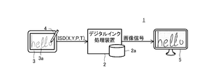
- FIG. 1 is a conceptual diagram showing an input system 1 according to the first embodiment of the present invention.
- the input system 1 includes a digital ink processing device 2 having a storage device 2a, a digitizer 3 (position detecting device) having a flat plate sensor 3a, an electronic pen 4 (indicator), and a display 5.
- the electronic pen 4 for example, a human finger or a simple plastic rod (stylus) can be used as the indicator.
- the computer 2, the digitizer 3, and the display 5 are drawn as separate devices, but some or all of them can be configured as an integrated device (tablet PC or the like).
- the input system 1 generates digital ink in the InkML format based on coordinate data input by the user drawing characters and pictures on the sensor 3a of the digitizer 3 using the electronic pen 4, and stores the digital ink in the storage device 2a. It has a function of recording and a function of generating an image signal from the recorded digital ink and reproducing it on the display 5.
- the digitizer 3 is coordinate data (X, Y) indicating the position of the electronic pen 4 within the surface of the sensor 3a based on the change in potential of these linear conductors caused by the approach of the electronic pen 4 to the surface of the sensor 3a. Configured to detect.
- the electronic pen 4 of the present embodiment is configured to detect the writing pressure data P at a predetermined time interval and transmit the detected writing pressure data P to the digitizer 3 as needed.
- the digitizer 3 is configured to detect the coordinate data (X, Y) and the pen pressure data P. Then, input sensor data ISD, which is a set of detected coordinate data (X, Y), corresponding writing pressure data P, and time data T indicating the detection time, is generated, and as shown in FIG.
- the ink processing apparatus 2 is configured to output through an IO unit (not shown). As a result, while the digitizer 3 detects the electronic pen 4, a series of input sensor data ISD is supplied to the digital ink processing apparatus 2 for each sampling rate of the sensor 3 a.
- the digital ink processing apparatus 2 is a personal computer, for example.
- a configuration provided in a normal computer such as a CPU or a communication circuit is provided.
- the storage device 2a includes a main storage device such as a main memory and an auxiliary storage device such as a hard disk.
- the functional blocks of the digital ink processing apparatus 2 shown in FIG. 2 are realized by the CPU of the digital ink processing apparatus 2 operating according to a program stored in the storage device 2a.
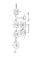
- FIG. 2 is a functional block diagram of the digital ink processing apparatus 2.
- the digital ink processing apparatus 2 is functionally configured to include an input processing unit 10, a stroke data generation unit 20, a digital ink generation unit 30, and a digital ink reproduction unit 40.
- the digital ink generation unit 30 includes a digital ink assembly unit 31, a mapping data generation unit 32, and an application order determination unit 33 as internal configurations.
- the input processing unit 10 extracts input sensor attributes ISA such as coordinate data (X, Y) and writing pressure data P from the input sensor data ISD supplied from the digitizer 3 via an interface such as USB and I2C, and the like on the operating system.
- Event data ED which is in a format that can be used by other programs that run on, is output.
- the input processing unit 10 is typically realized as a device driver corresponding to the digitizer 3 incorporated in an operating system that operates on the digital ink processing apparatus 2.
- Event type identification information ETYPE In addition to the point data PD including the coordinate data (X, Y) and the writing pressure data P, it identifies which part of the stroke the point data PD is.
- Event type identification information ETYPE Values taken by the event type identification information ETYPE include a pen-down state Pdown, a pen-moved state Pmvd, a pen-up state Pup, and the like.
- the input processing unit 10 detects that an indicator such as the electronic pen 4 or a finger has touched (pen-down) the digitizer 3, it generates point data PD including coordinate data (X, Y) corresponding to the contact position.
- Event data ED in which the pen-down state Pdown is set as the value of the event type identification information ETYPE is generated. Thereafter, while the electronic pen 4 and the indicator are slid on the digitizer 3, the input processing unit 10 sets the value of the event type identification information ETYPE together with a series of point data PD corresponding to a series of coordinate data (X, Y). The event data ED in which the value of the pen moved state Pmvd is set to is continuously generated. Finally, when the input processing unit 10 detects that the electronic pen 4 is lifted (pen-up) from the digitizer 3, the event data ED that specifies that the pen-up state Pup is specified as the value of the event type identification information ETYPE Is generated.
- the stroke data generation unit 20 is a functional unit that receives the event data ED from the input processing unit 10 and generates stroke data SD (first stroke data) including one or more point data PD.
- the stroke data generation unit 20 is typically realized by a program called a library or service executed by the CPU of the digital ink processing apparatus 2.
- the stroke data generation unit 20 refers to the value of the event type identification information ETYPE of the event data ED supplied from the input processing unit 10, and from the event data ED indicating the pen-down state Pdown to the event data ED indicating the pen-up state Pup.
- One stroke data SD including a series of point data PD included in the intervening event data ED is generated.
- the stroke data generation unit 20 uses the input sensor data ISD.
- the new coordinate data (X, Y) value obtained by performing smoothing processing such as weighted average or exponential smoothing or thinning processing on the value of the included coordinate data (X, Y) is used as the coordinate data of the point data PD.
- additional control points for determining the shape of an interpolation curve such as a Bezier curve are set as point data PD. There is a case.
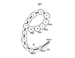
- FIG. 3 is a diagram for explaining the relationship between the point data PD and the stroke data SD.
- five broken line frames indicate five stroke data SD (SD0, SD1, SD2, SD3, SD0, SD3, SD3, SD3, SD0, SD2, SD3, SD) generated when five alphabets “h” “e” “l” “l” “o” are input. SD4).
- Each of the stroke data SD0 to SD4 includes a series of point data PD indicated by white circles in the figure.
- solid lines between white circles indicate that the point data PD indicated by white circles is a series.
- the stroke data SD0 corresponding to the alphabet “h” starts with the point data PD0 having an index value of 0 and ends with PD25 having an index value of 25. PD25 is included.
- the value of the point data number n of the point data PD included by the stroke data SD is different.
- OP shown in FIG. 3 indicates the origin coordinate of the coordinate system for the coordinate data (X, Y) included in the point data PD.
- the value of the coordinate data is a direction in which the X coordinate value increases in the right direction and a direction in which the Y coordinate value increases in the downward direction.
- the stroke data generation unit 20 generates the stroke data SD according to the description format of the ⁇ trace> element according to the format using InkML of Non-Patent Document 1 as the format of the stroke data SD.
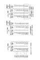
- FIG. 4 is a diagram showing the stroke data SD0 to SD4 of FIG. 3 generated according to the InkML format.
- FIG. 5 is a diagram in which only the stroke data SD1 corresponding to the alphabet “e” is extracted from the stroke data SD0 to SD4 corresponding to the five alphabets in FIG.
- the stroke data SD is expressed as a ⁇ trace> element, and each point data PD0 to PD14 is delimited using a comma (,) present at the end of each line in the figure as a delimiter. Generated by the format.
- each attribute data is delimited using one or more half-width spaces as delimiters.
- the first attribute (coordinate data X), the second attribute (coordinate data Y), and the third attribute (writing pressure data P), which are input sensor attributes ISA, are included in the stroke data SD. These three attribute data are retained as the values of the original data.
- the values of these three input sensor attributes ISA are arranged in each point data PD in the order of coordinate data X, coordinate data Y, and writing pressure data P.
- first point data PD0 having the index value 0 in the stroke data Sd1 shown in FIG. 5 “199” on the left is coordinate data X, “306” is coordinate data Y, and “1.0” is “1.0”.
- Writing pressure data P is obtained.
- the stroke data SD generated by the stroke data generation unit 20 is supplied to the digital ink assembly unit 31.
- the digital ink assembling unit 31 is configured to assemble the digital ink INKD based on the stroke data SD thus supplied and the one or more mapping data MD supplied from the application order determining unit 33.
- FIG. 6 is a diagram for explaining the digital ink INKD assembled by the digital ink assembly unit 31.
- the example in the figure is an example in which digital ink INKD is generated in accordance with the InkML format.
- the digital ink INKD includes an XML declaration starting with “ ⁇ ? Xml” and an ⁇ ink> element described between the line starting with “ ⁇ ink ...” and the ⁇ / ink> of the last line. Is done.
- the ⁇ ink> element includes a definition block DEB ( ⁇ definitions> element) and a stroke data description block SDB ( ⁇ stroke data SD> element).
- the definition block DEB includes a mapping data description block MDB and a drawing style data description block DDB.
- the mapping data description block MDB is a block in which mapping data MD indicating stroke data conversion rules is described.
- a conversion rule the value of the input sensor attribute ISA included in the stroke data SD described in the stroke data description block SDB is used as the value of the data before conversion, and a new drawing such as a line width and shading is calculated from the value of the data before conversion.
- a conversion rule func for obtaining the attribute value of the attribute DA is described.
- the drawing style data description block DDB is a block that describes a drawing style indicating a basic style when drawing stroke data SD such as the shape of the pen tip.
- the stroke data description block SDB is a block in which the stroke data SD is described.
- a plurality of stroke data SD such as the stroke data SD0 to SD4 shown in FIG. 4 are listed.
- the mapping data generation unit 32 is a functional unit that generates and outputs mapping data MD indicating a conversion rule for converting the input sensor attribute ISA included in the stroke data SD into the drawing attribute DA.
- the drawing attribute DA includes either a line width value W or a gray value (transparency A).
- the mapping data MD generated by the mapping data generation unit 32 includes range data rd (described later) indicating the application range of the conversion rule.
- the conversion function content func of the mapping data MD generated by the mapping data generation unit 32 is specified in advance by user settings.
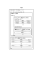
- FIG. 7 is a diagram showing various examples of the content func of the mapping data set by the user.
- FIG. 7A shows an example of a conversion rule in which the writing pressure value P is a value before conversion of the input sensor attribute ISA, and the value of the drawing attribute DA having the line width W is output as the value after conversion.
- the function indicated by func1 is a conversion rule in which the line width W is 10 times the writing pressure value P that takes a value between 0.0 and 1.0.
- the function indicated by func2a is a conversion rule in which the line width W is a value that is five times the writing pressure value P that takes a value between 0.0 and 1.0.
- the function indicated by func2b is a conversion rule in which the line width W is 20 times the writing pressure value P that takes a value between 0.0 and 1.0.
- FIG. 7B shows a drawing attribute DA having transparency A as a value before conversion of the input sensor attribute ISA with a speed V derived based on the coordinate data (X, Y) and time T.
- the example of the conversion rule which outputs the value of is shown.
- functions indicated by func3 and func3b indicate conversion rules in which the transparency increases monotonously as the speed V increases.
- the conversion rule can be arbitrarily specified by the user, and a function func2c that does not pass through the origin, a non-linear function func3b, or the like can be used as a function of the conversion rule of the mapping data MD.
- mapping data MD generated by the mapping data generation unit 32 will be described in more detail with reference to FIG.
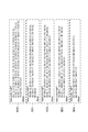
- FIG. 8 shows an example of mapping data MD according to the InkML format.
- the mapping data generating unit 32 according to the present embodiment is configured to generate two mapping data MD1 and MD2.
- mapping data MD1 (first mapping data) will be described.
- the seventh line indicates that the above expression is expressed using MathML.
- line width data W is generated by multiplying the writing pressure data P (representing variable p), which is the source, by a numerical value 10 ( ⁇ times />).
- the contents func1 of the conversion rule are shown. Note that the application range of the conversion rule by the function func1 is the entire stroke data SD, and therefore does not include data of the application range of the conversion rule.
- mapping data MD2 (second mapping data) will be described.
- the 23rd to 25th lines correspond to the conversion rule of FIG. 7 in which the line width data W is generated by multiplying the writing pressure data P (the variable p representing the source) by the numerical value 5 ( ⁇ times />).
- Contents func2a are shown. “Range” on the 18th line indicates the existence of range data rd (first range data) indicating the application range of the conversion rule by the function func2a, and an example ““ ⁇ 2, ⁇ 1 ”” of the range. ing.
- “ ⁇ 2” on the left side indicates the start point of the range
- “ ⁇ 1” indicates the end point of the range.
- each point data PD in the stroke data SD has an index value starting from 0.
- the range data rd uses index value information indicating the index value of the point data PD to indicate the range of stroke data.
- the index value information is an index value itself or a corrected index value obtained by correcting the index value by a calculation rule using a remainder operation.
- the calculation rule is expressed by, for example, the following expressions (1) and (2).
- i is an index value before correction
- j is a correction index value
- Mod (a, b) is a function for obtaining a remainder obtained when a is divided by b.
- the corrected index value j is an integer congruent with the corresponding index value i modulo the point data number n.
- the corrected index value j calculated by the equation (1) is “ ⁇ 1” and “ ⁇ 2” in order from the last index value (the corrected index value j of the nth point data PD) regardless of the total number n of point data PD. “ ⁇ 3”...
- it is determined whether the index value information is an index value or a corrected index value by determining whether the index value information included in the range data rd is positive or negative. Can do.
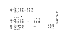
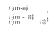
- FIGS. 9A to 9D are diagrams illustrating four examples of the range data rd and stroke ranges (end portions) in the stroke data SD0, the stroke data SD1, and the stroke data SD4 shown by the examples.
- a broken line frame in the figure is a stroke range corresponding to the range data rd in each example.
- the second expression from the end which is the end of the end of any stroke data with the same expression, is expressed using the corrected index value. It is possible to indicate a range from the point data PD to the last point data PD.
- the same expression can indicate the range of the first end data PD to the second point data PD, which is the first end. It becomes possible.
- range “ ⁇ 1, 0”
- a range including two ends can be shown by one expression. This is an effect obtained by handling the point data PD included in the stroke data SD with the index value and the corrected index value. This is particularly useful when special processing is required for both ends of the stroke.
- mapping data MD can be generated.
- the stroke data SD is converted into the point data PDn at the end to which the corrected index value ⁇ 1 is given and the point data PD0 at the tip to which the index value 0 is given. Can be handled as continuous cyclic data. As a result, it is possible to indicate the deformation of both end portions of the stroke data having a large change in the line width and shading of the ink data by one range data rd.
- the stroke data SD may be supplied to the mapping data generation unit 32.
- the mapping data generating unit 32 can determine the index value of the point data PD that is the target of the conversion rule and include it in the corresponding range data.
- the one or more mapping data MD generated by the mapping data generating unit 32 is supplied to the application order determining unit 33.
- the application order determination unit 33 is a functional unit that determines the application order when a plurality of mapping data MD is supplied from the mapping data generation unit 32.
- mapping data MD1 is applied after the mapping data MD2 is applied, the mapping data MD1 is applied to the point data PD0 to PDn of all index values included in the stroke data SD0 to SD5. Therefore, the application result of the mapping data MD2 is canceled.
- mapping data MD2 is applied after mapping data MD1 is applied, line width data W is generated for point data PD0 to PDn of all index values included in stroke data SD by mapping data MD1. Only the line width data W corresponding to the point data PD of the index value of a part (first end, both ends, etc.) can be corrected by the mapping data MD2 so as to overwrite the line width data W ( This will be described later with reference to FIG.
- the application order determination unit 33 has two mapping data MD configured to convert the same attribute data into the same attribute data, and the range data has an overlap.
- the order of application of the mapping data MD may be determined according to user settings such as overwriting the mapping data MD1 for all of the stroke data SD with the mapping data MD2 for a part of the stroke data SD. This makes it possible to obtain attribute data as intended by the user (line width data W in the example of FIG. 8).
- the digital ink assembly unit 31 arranges the stroke data SD supplied from the stroke data generation unit 20 in the stroke data description block SDB shown in FIG.
- the digital ink assembling unit 31 arranges one or a plurality of mapping data MD supplied from the application order determining unit 33 in the mapping data description block MDB shown in FIG. In this case, when a plurality of mapping data MD is supplied from the application order determining unit 33, the digital ink assembling unit 31 arranges the plurality of mapping data MD based on the application order determined by the application order determining unit 33. Determine the order. Although the specific arrangement order depends on the specification of the digital ink reproducing unit 40 described later, the mapping data MD to be applied first (mapping data MD1 in the example of FIG. 8) is the mapping data MD to be applied later (FIG. 8). In the example of FIG.
- the reproducing unit 30 interprets the digital ink INKD by arranging it so as to be above the mapping data MD2), in the order of the mapping data MD1, MD2, to MDm in order from the top of the data.
- the application order at the time of reproduction can be made the same order as the application order determined by the application order determining unit 33.
- the digital ink assembling unit 31 adds drawing style data DD describing a style related to the format of the stroke data SD to the setting data description block DDB.
- FIG. 10 shows, as an example of the drawing style data DD, drawing style information DD1 indicating the brush style set in the application when the stroke data SD is generated.
- the digital ink assembly unit 31 assembles the digital ink INKD according to the InkML format by combining the stroke data SD, the mapping data MD, and the drawing style data DD as an XML document.
- the digital ink assembling unit 31 converts the digital ink INKD thus assembled into a byte string using the XML file encoding method (such as UTF8) declared at the beginning of FIG. Output to network media. In this way, the digital ink processing apparatus 2 according to the present embodiment outputs the digital ink INKD.
- 2 is a functional unit that plays a role of reproducing the digital ink INKD generated by the digital ink generation unit 30 in the digital ink processing apparatus 2.
- stroke data SD (first stroke data) and mapping data MD are extracted from the digital ink INKD, and extracted for the input sensor attribute ISA included in the extracted stroke data SD.
- mapping data MD a process for generating corrected stroke data SD (second stroke data) including the value of the drawing attribute DA is included.
- the digital ink regeneration process will be specifically described with reference to FIG. In the following description, it is assumed that the digital ink INKD to be processed includes the mapping data description block MDB shown in FIG.
- FIG. 11A shows the stroke data SD1 extracted from the digital ink INKD by the digital ink reproducing unit 40.
- the stroke data SD1 includes, as the input sensor attribute ISA, three attribute data: first attribute data X indicating the X coordinate, second attribute data Y indicating the Y coordinate, and third attribute data P indicating the pen pressure value. Contains.
- the digital ink reproducing unit 40 sequentially extracts the mapping data MD1 and MD2 shown in FIG. 8 from the mapping data description block MDB in the digital ink INKD shown in FIG.
- the digital ink reproducing unit 40 first applies the mapping data MD1 extracted first out of the two extracted mapping data MD1 and MD2 to the stroke data SD1.
- the stroke data SD1 after the mapping data MD1 is applied is obtained.
- the stroke data SD after applying MD1 includes the value of the line width W, which is a new drawing attribute DA, as the fourth attribute data, in addition to the first to third attribute data X, Y, P before conversion.
- the digital ink reproducing unit 40 performs mapping for all strokes (point data PD of all indexes included in the stroke data SD) according to the rules of the ⁇ mapping> element. Processing is performed assuming that data MD1 is applied. Thereby, with respect to the mapping data MD1 shown in FIG. 8, the conversion rule is applied to all parts of the stroke data SD.
- a broken line frame indicated by rd1 indicates a range of strokes to which the conversion rule according to the mapping data MD1 is applied in the stroke data SD.
- the value in the broken line frame indicated by rd1 indicates the value of the line width W obtained from the mapping data MD1 having func1 (10 times) in FIG. 7 as the content of the conversion rule.
- the value of the fourth attribute data (line width W) is derived as a value 10 times the value of the writing pressure data P.
- the digital ink reproducing unit 40 applies the mapping data MD2 shown in FIG. 8 to the range (part) of the stroke data SD indicated by the range data rd described therein.
- the range data rd shown in FIG. 8 is “ ⁇ 2, ⁇ 1”, but FIG. 11C shows the case where the value of the range data rd is “ ⁇ 1, ⁇ 1”.
- An example is shown.
- a broken line frame indicated by rd2 in FIG. 11C indicates a range to which the mapping data MD2 is applied when the value of the range data rd is “ ⁇ 1, ⁇ 1”.
- the value in the broken line frame indicated by rd2 indicates the value of the drawing attribute DA (fourth attribute data) obtained from the mapping data MD2 having func2a (5 times) in FIG. 7 as the content of the conversion rule.
- the value of the line width W which is the fourth attribute data of the drawing attribute DA of the point data PD14 of a part (last part) of the stroke is partially reduced.
- the writing pressure data P is converted into line width data W by multiplying the writing pressure data P by five times, and the last point data whose application range is indicated by the index value ⁇ 1. This corresponds to the fact that only PD is described.
- the digital ink reproducing unit 40 that has generated the stroke data SD after conversion by deriving the drawing attribute DA from the value of the input sensor attribute ISA is based on other information such as the drawing style DD described above.
- An image signal is generated by applying an existing drawing processing method.
- FIG. 12 schematically shows an example of a drawing process described in Non-Patent Document 6 as an example of an existing drawing processing method.
- white circles PD0 to PD14 indicate 15 point data PD included in the stroke data SD1.
- the numbers in the white circles indicate the value of the fourth attribute W for each of the point data PD0 to PD15.
- the radius of each white circle is described as a value proportional to the value of the fourth attribute W.
- the point data PD0 has a diameter 10 as the value of the fourth attribute W
- the point data PD14 has a diameter 3 as the value of the fourth attribute (line width data W) obtained from the mapping data MD2. Listed in yen.
- the digital ink reproducing unit 40 derives two envelopes (inner envelope IE and outer envelope OE) that touch each circle of the point data PD0 to PD14. Then, the obtained two envelopes IE and OE are defined as contours of the shape of the stroke data SD1. For example, in this way, the digital ink reproducing unit 40 can generate an image signal in which the line width proportional to the line width data W is the stroke data line width.
- the drawing method of the converted stroke data SD is not limited to this, and an existing drawing method may be used.
- the image signal generated by the digital ink reproducing unit 40 is output to the display 5 as shown in FIG.
- the stroke data SD corrected by the mapping data MD2 is displayed for the stroke data SD0 to SD5 in a form visible to the user.
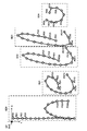
- FIGS. 13A to 13D show examples of the stroke data SD (stroke data SD0 to SD4) converted into image signals as described above.
- FIG. 13A shows stroke data obtained by applying the conversion rule func1 for obtaining the line width W by multiplying the writing pressure P by 10 with respect to the stroke data SD0 to SD4 shown in FIG.
- regenerated from SD is shown.
- FIG. 13B applies (1) the conversion rule func1 for obtaining the line width W by multiplying the writing pressure P by 10 with respect to the stroke data SD0 to SD4 shown in FIG. (2) An image signal reproduced from the stroke data SD obtained by applying the conversion rule func2a that multiplies the pen pressure P to 5 to obtain the line width W with respect to the end portion indicated by the broken line frame in the drawing. Is shown.
- 13C applies (1) the conversion rule func1 for obtaining the line width W by multiplying the writing pressure P by 10 with respect to the stroke data SD0 to SD4 shown in FIG. (2) Stroke data obtained by applying the conversion rule func2a to obtain the line width W by multiplying the writing pressure P by 5 with respect to both the end and the end indicated by the broken line frame in the drawing of the stroke.
- regenerated from SD is shown.
- FIG. 13D applies to the stroke data SD0 to SD4 shown in FIG. 3, (1) the conversion rule func1 for obtaining the line width W by multiplying the writing pressure P by 10 is applied to all parts of the stroke data. (2) Stroke data obtained by applying the conversion rule func2b, in which the writing pressure P is multiplied by 20 to obtain the line width W, to both the end and the end indicated by the broken line frame in the stroke diagram The image signal reproduced
- the line width W or the transparency A or the like is lost without losing data indicating the input sensor attribute ISA such as writing pressure data.
- Ink data INKD describing a conversion rule for deriving the value of the drawing attribute DA of the stroke data can be generated.
- the digital ink INKD can indicate from which value of the input sensor attribute ISA the value of the drawing attribute DA (line width W and transparency A) is derived.
- Changing the correspondence between the pen pressure data P and the line width W included in the ink INKD at once, or the pen pressure data stored in the digital ink INKD (although not directly used for drawing) P can also be used as a comparison parameter for signature authentication.
- digital ink INKD in which a rule for applying a conversion rule in mapping data MD to a partial range of stroke data SD is generated. It becomes possible. Therefore, as in the example described above, it is possible to configure so that the conversion rule is applied only to the start point and the end point of the stroke data SD. Therefore, as shown in FIG. 13A to FIG. It is possible to generate digital ink INKD having In addition, in order to express the end point of the range data using the index value and the corrected index value obtained by using the remainder operation, a conversion rule that specifies the end part or both the end part and the front end part is set as stroke data. It can be obtained in advance before the SD is generated.
- the input system 1 is the first implementation in terms of the contents of the stroke data SD output from the stroke data generation unit 20 and the internal processing of the mapping data generation unit 32 and the digital ink reproduction unit 40, respectively. Since it is different from the input system 1 according to the form, the same components as those of the first embodiment are denoted by the same reference numerals, and the description thereof will be omitted. In the following, attention is paid to differences from the first embodiment. explain.
- the stroke data generation unit 20 generates stroke data SD including three types of input sensor attributes ISA: coordinate data X, coordinate data Y, and time data T.
- FIG. 14 shows stroke data SD5 including ten point data PD0 to PD9 as an example of the stroke data SD generated by the stroke data generation unit 20 according to the present embodiment.
- the stroke data SD is generated in the InkML format, and specifically, a format in which each point data PD is delimited by a comma (,). Is generated by In each point data PD, each attribute data is delimited by a half-width space.
- the arrangement of each attribute data in the point data PD is in the order of coordinate data X, coordinate data Y, and time data T.
- “8” on the left side is the coordinate data X
- “0” in the center is the coordinate data Y
- the numerical value 16 on the right side of “'16” on the right side is the time.
- Data T Note that the time data T of each point data PD is expressed by the elapsed time from the time corresponding to the first index value being 0 milliseconds.
- FIG. 14 shows an example in which coordinate data (X, Y) is obtained at a constant interval of 16 milliseconds. Also for the coordinate data (X, Y), the Y coordinate is fixed at 0, and is obtained when the electronic pen 4 is moved only in the X direction at a constant acceleration (speed increases by 8 every 16 milliseconds). The example of the coordinate to be shown is shown.
- the mapping data generation unit 32 has a first input sensor attribute ISA (for example, coordinate data (X, Y)) of the first point data PDi among a plurality of point data PD included in one stroke data SD.
- the transparency data A is based on the value of the time data T) and the value of the first input sensor attribute ISA included in the second point data PDi + 1 whose index value is different from that of the first point data PDi. It is configured to generate mapping data MD including a conversion rule for obtaining the drawing attribute DA.
- mapping data MD generated by the mapping data generation unit 32 will be described in more detail with reference to FIG.
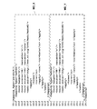
- FIG. 15 is a diagram showing mapping data MD3 generated by the mapping data generation unit 32 according to the present embodiment.
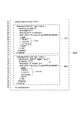
- the third to seventh lines are parts for defining input sensor attributes (X, Y, T) as conversion sources and drawing attributes (transparency A) obtained by the conversion.
- the 11th to 37th lines are parts indicating conversion rules included in the mapping data MD3. Specifically, a conversion rule is described in which transparency data A i corresponding to the i-th index value is generated by the following formulas (2) and (3).
- X i , X i ⁇ 1 , Y i , Y i ⁇ 1 , T i , and T i ⁇ 1 in Equation (3) are coordinate data X and i ⁇ 1 corresponding to the i-th index value, respectively.
- the characteristic of the conversion rule according to the above formulas (2) and (3) is that, when generating the transparency data A i corresponding to the i-th index value, refer to the attribute data corresponding to the index value that is not the i-th index value. There is in point. Specifically, the attribute data corresponding to the previous index value i ⁇ 1 is referred to, and V i obtained by Expression (3) is changed from the position corresponding to the index value i ⁇ 1 to the index value i. The moving speed of the electronic pen 4 until it moves to the corresponding position is shown. In the conversion rule according to Expression (2), a function (func3 shown in FIG. 7B) is set such that the transparency increases as the moving speed V i increases.
- mapping data MD3 shown in FIG. 15 the 22nd line “'x” indicated by dx, the 27th line “′ y” indicated by dy, and the “′ t” on the 32nd line indicated by dt are “X i -X i-1 ”, respectively. It means “Y i -Y i-1 ” or “T i -T i-1 ”.
- a portion surrounded by a broken line frame A in FIG. 15 indicates a value obtained by squaring “X i ⁇ X i ⁇ 1 ” which is the displacement amount of X.
- a portion surrounded by a broken line frame B indicates a value obtained by squaring “Y i ⁇ Y i ⁇ 1 ” which is a displacement amount of Y.
- a portion surrounded by a broken line frame C in the figure indicates a displacement amount in a two-dimensional plane corresponding to the numerator on the right side of Expression (3).
- a portion surrounded by a broken line frame D corresponds to the entire right side of the equation (3), and indicates the speed of the section of time “T i ⁇ T i ⁇ 1 ”.
- mapping data MD3 shown in FIG. 14 describes the conversion rule from the input sensor attribute ISA to the drawing attribute DA (transparency A) represented by the expressions (2) and (3).
- the digital ink processing apparatus 2 generates and outputs the digital ink INKD including the mapping data MD3.
- the digital ink data reproducing unit 30 extracts the stroke data SD5 and the mapping data MD3 from the digital ink INKD.
- FIG. 16A shows the conversion source stroke data SD5 extracted from the digital ink INKD by the digital ink reproducing unit 40.
- the stroke data SD5 includes, as the input sensor attribute ISA, first attribute data X indicating the X coordinate, second attribute data Y indicating the Y coordinate, and third attribute data T indicating the time information. Contains three data.
- FIG. 16B shows stroke data SD5 obtained by applying the mapping data MD3.
- the stroke data SD5 at this point includes transparency data A of the fourth attribute (drawing attribute DA) derived from the input sensor attribute ISA. Since the transparency data A 0 corresponding to the first index value cannot be obtained by the above formulas (2) and (3), the digital ink reproducing unit 40 conveniently uses the value of the transparency data A 1 . 10 is set as the value 10 of the transparency data A 0 .
- the default value 0 is set for the transparency when no value is obtained for other parts such as the head part.
- the stroke data SD including the transparency A obtained by the conversion rule can be obtained.
- the digital ink reproducing unit 40 that has generated the stroke data SD after conversion by deriving the drawing attribute DA from the value of the input sensor attribute ISA is based on other information such as the drawing style DD described above.
- An image signal is generated by applying an existing drawing processing method.
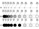
- FIG. 17 is a diagram for explaining the stroke data SD according to the present embodiment.
- 17 shows the positional relationship of 10 coordinate data (X, Y) from point data PD0 to PD9 included in the stroke data SD5 shown in FIG.
- the middle part B of FIG. 17 expresses each point data PD0 to PD9 as a black circle, and stroke data SD5 obtained by setting the value of the transparency A shown in FIG. It is an image figure of the image signal produced
- the lower part C of FIG. 17 represents each piece of point data PD0 to PD9 as a black circle, and stroke data SD5 obtained by setting the value of the transparency A shown in FIG. It is an image figure of the image signal produced
- FIG. 18 is another diagram for explaining the effect of the conversion rule in which the transparency A increases with the speed V.
- data such as a felt pen is applied as the brush type set in the drawing style information DD1 (see FIGS. 6 and 10)
- the data moves from the left side to the right side in the drawing, similarly to the stroke data SD5 shown in FIG.
- the moving speed (speed) of the indicator increases, an image signal in which the transparency A increases is shown.
- Mapping data MD that defines the relationship can be generated.
- the drawing attribute DA such as the line width W and the transparency A is derived.
- the type of original data used to give the transparency A and line width W (whether writing pressure data was included or data derived from speed, etc.) can be recorded. it can.
- each point data PD constituting the stroke data SD includes both the pen pressure data P and the time data T, and mapping data for converting the pen pressure data P into line width data W into the digital ink INKD.
- mapping data MD for obtaining transparency data A from the stroke speed may be included.
- the conversion rule applied to the range specified by the range data in the first embodiment may not be for deriving the drawing attribute DA such as the line width W and the transparency A from the input sensor attribute ISA. It may be used when it is desired to change the geometric shape using a conventional affine transformation or the like for a part of the stroke.
- the attributes obtained by conversion using the statistical values of the same input sensor attribute ISA are not limited to the drawing attributes DD such as the line width W and the transparency A.
- the coordinate data included in the stroke data SD may be used as the original data, and the coordinate data of the point data PD used in actual drawing may be obtained by applying a conversion rule such as a weighted average.
- the present invention can also be regarded as an invention of a method for sequentially executing the processes of the stroke data generation unit 20 and the digital ink generation unit 30 using a computer, and these processes can be executed. Needless to say, it can also be regarded as an invention of a computer program describing a program.
Landscapes
- Engineering & Computer Science (AREA)
- Theoretical Computer Science (AREA)
- General Engineering & Computer Science (AREA)
- Physics & Mathematics (AREA)
- General Physics & Mathematics (AREA)
- Human Computer Interaction (AREA)
- Computational Linguistics (AREA)
- General Health & Medical Sciences (AREA)
- Health & Medical Sciences (AREA)
- Audiology, Speech & Language Pathology (AREA)
- Artificial Intelligence (AREA)
- User Interface Of Digital Computer (AREA)
- Image Generation (AREA)
Priority Applications (5)
| Application Number | Priority Date | Filing Date | Title |
|---|---|---|---|
| EP14908428.7A EP3079052A4 (de) | 2014-12-18 | 2014-12-18 | Digitale tintenerzeugungsvorrichtung, digitales tintenerzeugungsverfahren und digitale tintenwiedergabevorrichtung |
| PCT/JP2014/083506 WO2016098218A1 (ja) | 2014-12-18 | 2014-12-18 | デジタルインク生成装置、デジタルインク生成方法及びデジタルインク再生装置 |
| JP2015511540A JP5775240B1 (ja) | 2014-12-18 | 2014-12-18 | デジタルインク生成装置、デジタルインク生成方法、及びプログラム |
| US14/919,573 US10747421B2 (en) | 2014-12-18 | 2015-10-21 | Digital ink generating apparatus, method and program, and digital ink reproducing apparatus, method and program |
| US16/921,711 US11422693B2 (en) | 2014-12-18 | 2020-07-06 | Digital ink generating apparatus, method and program, and digital ink reproducing apparatus, method and program |
Applications Claiming Priority (1)
| Application Number | Priority Date | Filing Date | Title |
|---|---|---|---|
| PCT/JP2014/083506 WO2016098218A1 (ja) | 2014-12-18 | 2014-12-18 | デジタルインク生成装置、デジタルインク生成方法及びデジタルインク再生装置 |
Related Child Applications (1)
| Application Number | Title | Priority Date | Filing Date |
|---|---|---|---|
| US14/919,573 Continuation US10747421B2 (en) | 2014-12-18 | 2015-10-21 | Digital ink generating apparatus, method and program, and digital ink reproducing apparatus, method and program |
Publications (1)
| Publication Number | Publication Date |
|---|---|
| WO2016098218A1 true WO2016098218A1 (ja) | 2016-06-23 |
Family
ID=54192556
Family Applications (1)
| Application Number | Title | Priority Date | Filing Date |
|---|---|---|---|
| PCT/JP2014/083506 WO2016098218A1 (ja) | 2014-12-18 | 2014-12-18 | デジタルインク生成装置、デジタルインク生成方法及びデジタルインク再生装置 |
Country Status (4)
| Country | Link |
|---|---|
| US (2) | US10747421B2 (de) |
| EP (1) | EP3079052A4 (de) |
| JP (1) | JP5775240B1 (de) |
| WO (1) | WO2016098218A1 (de) |
Families Citing this family (11)
| Publication number | Priority date | Publication date | Assignee | Title |
|---|---|---|---|---|
| US9740310B2 (en) * | 2015-05-22 | 2017-08-22 | Adobe Systems Incorporated | Intuitive control of pressure-sensitive stroke attributes |
| US10049289B2 (en) * | 2016-02-12 | 2018-08-14 | Wacom Co., Ltd. | Method and system for generating and selectively outputting two types of ink vector data |
| US20170236318A1 (en) * | 2016-02-15 | 2017-08-17 | Microsoft Technology Licensing, Llc | Animated Digital Ink |
| US10417237B2 (en) * | 2016-05-24 | 2019-09-17 | International Business Machines Corporation | Sorting tables in analytical databases |
| CN108335340B (zh) * | 2017-01-20 | 2022-03-18 | 山西大学 | 压力触摸屏手写输入呈现为具有型笔特征笔迹的方法 |
| US10248226B2 (en) * | 2017-02-10 | 2019-04-02 | Microsoft Technology Licensing, Llc | Configuring digital pens for use across different applications |
| US10402642B2 (en) | 2017-05-22 | 2019-09-03 | Microsoft Technology Licensing, Llc | Automatically converting ink strokes into graphical objects |
| US20190155895A1 (en) * | 2017-11-20 | 2019-05-23 | Google Llc | Electronic text pen systems and methods |
| CN110222327B (zh) * | 2019-06-12 | 2023-06-30 | 杭州米络星科技(集团)有限公司 | 一种教育直播课件的制作方法及展示方法 |
| KR102149105B1 (ko) * | 2019-09-18 | 2020-08-27 | 세종대학교산학협력단 | 혼합현실 기반 3차원 스케치 장치 및 방법 |
| CN114585992A (zh) * | 2020-09-29 | 2022-06-03 | 京东方科技集团股份有限公司 | 书写轨迹处理方法、触控设备、书写系统及存储介质 |
Citations (5)
| Publication number | Priority date | Publication date | Assignee | Title |
|---|---|---|---|---|
| JPH08320756A (ja) * | 1995-05-24 | 1996-12-03 | Sharp Corp | データ入力手段を持つ電子機器 |
| JP2013045362A (ja) * | 2011-08-25 | 2013-03-04 | Konica Minolta Business Technologies Inc | 電子情報端末及び領域設定制御プログラム |
| JP2013137696A (ja) * | 2011-12-28 | 2013-07-11 | Sharp Corp | 電子機器、表示制御方法、およびプログラム |
| WO2014147716A1 (ja) * | 2013-03-18 | 2014-09-25 | 株式会社 東芝 | 電子機器および手書き文書処理方法 |
| JP2014225188A (ja) * | 2013-05-17 | 2014-12-04 | 株式会社リコー | 情報処理装置、プログラム、情報処理システム及び情報表示方法 |
Family Cites Families (14)
| Publication number | Priority date | Publication date | Assignee | Title |
|---|---|---|---|---|
| JPH06222879A (ja) | 1993-01-27 | 1994-08-12 | Matsushita Electric Ind Co Ltd | 筆跡表示方法および筆跡表示装置 |
| JPH1186016A (ja) * | 1997-09-09 | 1999-03-30 | Canon Inc | 情報処理方法及び装置及びその記憶媒体 |
| SG147292A1 (en) * | 1999-10-25 | 2008-11-28 | Silverbrook Res Pty Ltd | Universal pen and sensing |
| US7158675B2 (en) | 2002-05-14 | 2007-01-02 | Microsoft Corporation | Interfacing with ink |
| US7009594B2 (en) * | 2002-10-31 | 2006-03-07 | Microsoft Corporation | Universal computing device |
| US7345236B2 (en) * | 2003-02-03 | 2008-03-18 | Terra Knights Music, Inc. | Method of automated musical instrument finger finding |
| US7310091B2 (en) * | 2003-09-16 | 2007-12-18 | Acer Incorporated | Handwriting pen capable of simulating different strokes |
| US20080143691A1 (en) * | 2005-11-23 | 2008-06-19 | Quiteso Technologies, Llc | Systems and methods for enabling tablet PC/pen to paper space |
| WO2008141250A2 (en) * | 2007-05-09 | 2008-11-20 | Adapx, Inc. | Digital paper-enabled products and methods relating to same |
| KR101080255B1 (ko) * | 2009-07-21 | 2011-11-08 | (주)펜앤프리 | 필기 패턴에 따른 필기 정보 입력 장치 및 필기 정보 입력 방법 |
| US20130201162A1 (en) * | 2012-02-05 | 2013-08-08 | Ian Daniel Cavilia | Multi-purpose pen input device for use with mobile computers |
| US9013454B2 (en) * | 2012-03-02 | 2015-04-21 | Ricoh Co., Ltd. | Associating strokes with documents based on the document image |
| US10620775B2 (en) * | 2013-05-17 | 2020-04-14 | Ultrahaptics IP Two Limited | Dynamic interactive objects |
| US10055030B2 (en) * | 2013-05-17 | 2018-08-21 | Apple Inc. | Dynamic visual indications for input devices |
-
2014
- 2014-12-18 JP JP2015511540A patent/JP5775240B1/ja active Active
- 2014-12-18 WO PCT/JP2014/083506 patent/WO2016098218A1/ja active Application Filing
- 2014-12-18 EP EP14908428.7A patent/EP3079052A4/de active Pending
-
2015
- 2015-10-21 US US14/919,573 patent/US10747421B2/en active Active
-
2020
- 2020-07-06 US US16/921,711 patent/US11422693B2/en active Active
Patent Citations (5)
| Publication number | Priority date | Publication date | Assignee | Title |
|---|---|---|---|---|
| JPH08320756A (ja) * | 1995-05-24 | 1996-12-03 | Sharp Corp | データ入力手段を持つ電子機器 |
| JP2013045362A (ja) * | 2011-08-25 | 2013-03-04 | Konica Minolta Business Technologies Inc | 電子情報端末及び領域設定制御プログラム |
| JP2013137696A (ja) * | 2011-12-28 | 2013-07-11 | Sharp Corp | 電子機器、表示制御方法、およびプログラム |
| WO2014147716A1 (ja) * | 2013-03-18 | 2014-09-25 | 株式会社 東芝 | 電子機器および手書き文書処理方法 |
| JP2014225188A (ja) * | 2013-05-17 | 2014-12-04 | 株式会社リコー | 情報処理装置、プログラム、情報処理システム及び情報表示方法 |
Non-Patent Citations (7)
| Title |
|---|
| ERIK DAHLSTROM: "Scalable Vector Graphics (SVG) 1.1 (Second Edition) W3C Recommendation 16 August 2011", W3C, 16 August 2011 (2011-08-16) |
| IAN HICKSON: "A vocabulary and associated APIs for HTML and XHTML W3C Recommendation 28 October 2014", W3C, 28 October 2014 (2014-10-28), Retrieved from the Internet <URL:http://www.w3.org/TR/html5> |
| INK SERIALIZED FORMAT SPECIFICATION, 11 December 2014 (2014-12-11) |
| L.M. MESTETSKII: "Fat Curves and Representation of Planar Figures", DEPARTMENT OF INFORMATION TECHNOLOGIES, TVER' STATE UNIVERSITY, TVER, RUSSIA, 2000 |
| RON AUSBROOKS: "Mathematical Markup Language (MathML) Version 2.0 (Second Edition) W3C Recommendation 21 October 2003", W3C, 21 October 2003 (2003-10-21), Retrieved from the Internet <URL:http://www.w3.org/TR/MathML2> |
| See also references of EP3079052A4 |
| YI-MIN CHEE: "Ink Markup Language (InkML) W3C Recommendation 20 September 2011", W3C, 20 September 2011 (2011-09-20) |
Also Published As
| Publication number | Publication date |
|---|---|
| JP5775240B1 (ja) | 2015-09-09 |
| US20200333952A1 (en) | 2020-10-22 |
| US10747421B2 (en) | 2020-08-18 |
| US20160179365A1 (en) | 2016-06-23 |
| JPWO2016098218A1 (ja) | 2017-04-27 |
| US11422693B2 (en) | 2022-08-23 |
| EP3079052A4 (de) | 2017-08-16 |
| EP3079052A1 (de) | 2016-10-12 |
Similar Documents
| Publication | Publication Date | Title |
|---|---|---|
| JP5775240B1 (ja) | デジタルインク生成装置、デジタルインク生成方法、及びプログラム | |
| US11580761B2 (en) | Ink file searching method, apparatus, and program | |
| JP6728036B2 (ja) | インクからテキスト表現への変換 | |
| US20160048318A1 (en) | Detecting selection of digital ink | |
| Zhang et al. | Viscode: Embedding information in visualization images using encoder-decoder network | |
| US8209598B1 (en) | Exporting electronic documents from rich internet applications | |
| US20140225928A1 (en) | Manipulation of textual content data for layered presentation | |
| US9772978B2 (en) | Touch input visualizations based on user interface context | |
| US10818050B2 (en) | Vector graphic font character generation techniques | |
| US20170131801A1 (en) | Method for displaying handwriting in a pdf file | |
| JP6526504B2 (ja) | デジタルインク生成装置、デジタルインク生成方法、及びプログラム | |
| WO2016018682A1 (en) | Processing image to identify object for insertion into document | |
| JP4868830B2 (ja) | コンテクスト・ツリーにおける分析代替案 | |
| JP6710803B2 (ja) | デジタルインクファイル再生装置、デジタルインクファイル再生方法、及びプログラム | |
| CN106250035B (zh) | 动态生成个人化手写字型的系统和方法 | |
| US9442576B2 (en) | Method and system for combining paper-driven and software-driven design processes | |
| JP5645481B2 (ja) | 装置、方法、及びプログラム | |
| JP7320157B1 (ja) | コンテンツ評価装置、プログラム、方法、及びシステム | |
| US20240168575A1 (en) | Input support apparatus, method, computer-readable medium, and input system | |
| WO2023145429A1 (ja) | コンテンツ評価装置、プログラム、方法、及びシステム | |
| WO2023145227A1 (ja) | コンテンツ評価装置、プログラム、方法、及びシステム | |
| JP2013161375A (ja) | 編集システム | |
| Michail | Essential Silverlight 3 |
Legal Events
| Date | Code | Title | Description |
|---|---|---|---|
| ENP | Entry into the national phase |
Ref document number: 2015511540 Country of ref document: JP Kind code of ref document: A |
|
| REEP | Request for entry into the european phase |
Ref document number: 2014908428 Country of ref document: EP |
|
| WWE | Wipo information: entry into national phase |
Ref document number: 2014908428 Country of ref document: EP |
|
| 121 | Ep: the epo has been informed by wipo that ep was designated in this application |
Ref document number: 14908428 Country of ref document: EP Kind code of ref document: A1 |
|
| NENP | Non-entry into the national phase |
Ref country code: DE |