WO2016093080A1 - 充電器、電流制御方法、及び充電システム - Google Patents
充電器、電流制御方法、及び充電システム Download PDFInfo
- Publication number
- WO2016093080A1 WO2016093080A1 PCT/JP2015/083336 JP2015083336W WO2016093080A1 WO 2016093080 A1 WO2016093080 A1 WO 2016093080A1 JP 2015083336 W JP2015083336 W JP 2015083336W WO 2016093080 A1 WO2016093080 A1 WO 2016093080A1
- Authority
- WO
- WIPO (PCT)
- Prior art keywords
- current
- value
- charger
- power
- storage device
- Prior art date
- Legal status (The legal status is an assumption and is not a legal conclusion. Google has not performed a legal analysis and makes no representation as to the accuracy of the status listed.)
- Ceased
Links
Images







Classifications
-
- H—ELECTRICITY
- H02—GENERATION; CONVERSION OR DISTRIBUTION OF ELECTRIC POWER
- H02J—ELECTRIC POWER NETWORKS; CIRCUIT ARRANGEMENTS OR SYSTEMS FOR SUPPLYING OR DISTRIBUTING ELECTRIC POWER; SYSTEMS FOR STORING ELECTRIC ENERGY
- H02J3/00—Circuit arrangements for AC mains or AC distribution networks
- H02J3/12—Arrangements for adjusting voltage in AC networks by changing a characteristic of the network load
- H02J3/14—Arrangements for adjusting voltage in AC networks by changing a characteristic of the network load by switching loads on to, or off from, the networks, e.g. progressively balanced loading
-
- H—ELECTRICITY
- H02—GENERATION; CONVERSION OR DISTRIBUTION OF ELECTRIC POWER
- H02J—ELECTRIC POWER NETWORKS; CIRCUIT ARRANGEMENTS OR SYSTEMS FOR SUPPLYING OR DISTRIBUTING ELECTRIC POWER; SYSTEMS FOR STORING ELECTRIC ENERGY
- H02J7/00—Circuit arrangements for charging or discharging batteries or for supplying loads from batteries
- H02J7/02—Circuit arrangements for charging or discharging batteries or for supplying loads from batteries for charging batteries from AC mains by converters
-
- H—ELECTRICITY
- H02—GENERATION; CONVERSION OR DISTRIBUTION OF ELECTRIC POWER
- H02J—ELECTRIC POWER NETWORKS; CIRCUIT ARRANGEMENTS OR SYSTEMS FOR SUPPLYING OR DISTRIBUTING ELECTRIC POWER; SYSTEMS FOR STORING ELECTRIC ENERGY
- H02J2105/00—Networks for supplying or distributing electric power characterised by their spatial reach or by the load
- H02J2105/50—Networks for supplying or distributing electric power characterised by their spatial reach or by the load for selectively controlling the operation of the loads
- H02J2105/51—Networks for supplying or distributing electric power characterised by their spatial reach or by the load for selectively controlling the operation of the loads according to a condition being electrical
-
- H—ELECTRICITY
- H02—GENERATION; CONVERSION OR DISTRIBUTION OF ELECTRIC POWER
- H02J—ELECTRIC POWER NETWORKS; CIRCUIT ARRANGEMENTS OR SYSTEMS FOR SUPPLYING OR DISTRIBUTING ELECTRIC POWER; SYSTEMS FOR STORING ELECTRIC ENERGY
- H02J2105/00—Networks for supplying or distributing electric power characterised by their spatial reach or by the load
- H02J2105/50—Networks for supplying or distributing electric power characterised by their spatial reach or by the load for selectively controlling the operation of the loads
- H02J2105/59—Networks for supplying or distributing electric power characterised by their spatial reach or by the load for selectively controlling the operation of the loads one of the loads acting as leader and the other or others acting as followers
-
- Y—GENERAL TAGGING OF NEW TECHNOLOGICAL DEVELOPMENTS; GENERAL TAGGING OF CROSS-SECTIONAL TECHNOLOGIES SPANNING OVER SEVERAL SECTIONS OF THE IPC; TECHNICAL SUBJECTS COVERED BY FORMER USPC CROSS-REFERENCE ART COLLECTIONS [XRACs] AND DIGESTS
- Y02—TECHNOLOGIES OR APPLICATIONS FOR MITIGATION OR ADAPTATION AGAINST CLIMATE CHANGE
- Y02B—CLIMATE CHANGE MITIGATION TECHNOLOGIES RELATED TO BUILDINGS, e.g. HOUSING, HOUSE APPLIANCES OR RELATED END-USER APPLICATIONS
- Y02B70/00—Technologies for an efficient end-user side electric power management and consumption
- Y02B70/30—Systems integrating technologies related to power network operation and communication or information technologies for improving the carbon footprint of the management of residential or tertiary loads, i.e. smart grids as climate change mitigation technology in the buildings sector, including also the last stages of power distribution and the control, monitoring or operating management systems at local level
-
- Y—GENERAL TAGGING OF NEW TECHNOLOGICAL DEVELOPMENTS; GENERAL TAGGING OF CROSS-SECTIONAL TECHNOLOGIES SPANNING OVER SEVERAL SECTIONS OF THE IPC; TECHNICAL SUBJECTS COVERED BY FORMER USPC CROSS-REFERENCE ART COLLECTIONS [XRACs] AND DIGESTS
- Y02—TECHNOLOGIES OR APPLICATIONS FOR MITIGATION OR ADAPTATION AGAINST CLIMATE CHANGE
- Y02B—CLIMATE CHANGE MITIGATION TECHNOLOGIES RELATED TO BUILDINGS, e.g. HOUSING, HOUSE APPLIANCES OR RELATED END-USER APPLICATIONS
- Y02B70/00—Technologies for an efficient end-user side electric power management and consumption
- Y02B70/30—Systems integrating technologies related to power network operation and communication or information technologies for improving the carbon footprint of the management of residential or tertiary loads, i.e. smart grids as climate change mitigation technology in the buildings sector, including also the last stages of power distribution and the control, monitoring or operating management systems at local level
- Y02B70/3225—Demand response systems, e.g. load shedding, peak shaving
-
- Y—GENERAL TAGGING OF NEW TECHNOLOGICAL DEVELOPMENTS; GENERAL TAGGING OF CROSS-SECTIONAL TECHNOLOGIES SPANNING OVER SEVERAL SECTIONS OF THE IPC; TECHNICAL SUBJECTS COVERED BY FORMER USPC CROSS-REFERENCE ART COLLECTIONS [XRACs] AND DIGESTS
- Y02—TECHNOLOGIES OR APPLICATIONS FOR MITIGATION OR ADAPTATION AGAINST CLIMATE CHANGE
- Y02T—CLIMATE CHANGE MITIGATION TECHNOLOGIES RELATED TO TRANSPORTATION
- Y02T90/00—Enabling technologies or technologies with a potential or indirect contribution to GHG emissions mitigation
- Y02T90/10—Technologies relating to charging of electric vehicles
- Y02T90/16—Information or communication technologies improving the operation of electric vehicles
- Y02T90/167—Systems integrating technologies related to power network operation and communication or information technologies for supporting the interoperability of electric or hybrid vehicles, i.e. smartgrids as interface for battery charging of electric vehicles [EV] or hybrid vehicles [HEV]
-
- Y—GENERAL TAGGING OF NEW TECHNOLOGICAL DEVELOPMENTS; GENERAL TAGGING OF CROSS-SECTIONAL TECHNOLOGIES SPANNING OVER SEVERAL SECTIONS OF THE IPC; TECHNICAL SUBJECTS COVERED BY FORMER USPC CROSS-REFERENCE ART COLLECTIONS [XRACs] AND DIGESTS
- Y04—INFORMATION OR COMMUNICATION TECHNOLOGIES HAVING AN IMPACT ON OTHER TECHNOLOGY AREAS
- Y04S—SYSTEMS INTEGRATING TECHNOLOGIES RELATED TO POWER NETWORK OPERATION, COMMUNICATION OR INFORMATION TECHNOLOGIES FOR IMPROVING THE ELECTRICAL POWER GENERATION, TRANSMISSION, DISTRIBUTION, MANAGEMENT OR USAGE, i.e. SMART GRIDS
- Y04S20/00—Management or operation of end-user stationary applications or the last stages of power distribution; Controlling, monitoring or operating thereof
- Y04S20/20—End-user application control systems
- Y04S20/222—Demand response systems, e.g. load shedding, peak shaving
-
- Y—GENERAL TAGGING OF NEW TECHNOLOGICAL DEVELOPMENTS; GENERAL TAGGING OF CROSS-SECTIONAL TECHNOLOGIES SPANNING OVER SEVERAL SECTIONS OF THE IPC; TECHNICAL SUBJECTS COVERED BY FORMER USPC CROSS-REFERENCE ART COLLECTIONS [XRACs] AND DIGESTS
- Y04—INFORMATION OR COMMUNICATION TECHNOLOGIES HAVING AN IMPACT ON OTHER TECHNOLOGY AREAS
- Y04S—SYSTEMS INTEGRATING TECHNOLOGIES RELATED TO POWER NETWORK OPERATION, COMMUNICATION OR INFORMATION TECHNOLOGIES FOR IMPROVING THE ELECTRICAL POWER GENERATION, TRANSMISSION, DISTRIBUTION, MANAGEMENT OR USAGE, i.e. SMART GRIDS
- Y04S20/00—Management or operation of end-user stationary applications or the last stages of power distribution; Controlling, monitoring or operating thereof
- Y04S20/20—End-user application control systems
- Y04S20/242—Home appliances
Definitions
- the present invention relates to control of current output from a charger to a power storage device.
- the charging rate (the current that flows through the battery when the battery is fully charged in one hour) increases, so the charger to the power storage device The output power increases.
- the charger of the embodiment compares the first current value obtained by dividing the desired power by the number of power storage devices to be charged with the current command value from the power storage device to be charged, and compares the first current value. When the value is smaller than the current command value, the current output to the power storage device to be charged is controlled according to the first current value.
- the total output power of each charger can be prevented from exceeding a desired power.
- FIG. 1 is a diagram illustrating an example of a charging system including the charger according to the embodiment.
- the charging system shown in FIG. 1 includes a plurality of chargers 1.
- the charger 1 for obtaining the limit power value is a master charger 1
- the other charger 1 is a slave charger 1.
- Each charger 1 supplies electric power to a power storage device 4 mounted on a vehicle 3 such as an electric forklift or a plug-in hybrid vehicle using electric power supplied from a commercial power source 2.
- Each charger 1 includes a power supply unit 11 and a control unit 12.
- the power supply unit 11 is configured by, for example, an AC / DC converter, and converts AC power supplied from the commercial power supply 2 into DC power. Further, the power supply unit 11 converts the output voltage of the commercial power supply 2 into a predetermined voltage.
- the control unit 12 controls the operation of the power supply unit 11 such that a current corresponding to a current command value transmitted from the power storage device 4 that is the power supply destination of the control unit 12 is output from the power supply unit 11.
- Each control unit 12 is connected in a ring shape via a communication line 13.
- Each control unit 12 may be connected to a bus-type network.
- the control unit 12 of the master charger 1 transmits the limit power value to the control unit 12 of the slave charger 1.
- each control part 12 calculates
- each control part 12 updates the output possible current value of the power supply part 11 based on a 1st current value, and transmits the output possible current value after the update to the electrical storage apparatus 4 of an own electric power supply destination. .
- each control unit 12 compares the first current value with the current command value, and when the first current value is smaller than the current command value, the power storage device 4 that is charged according to the first current value. It controls the current output to (the power storage device 4 of its own power supply destination).
- each control unit 12 controls the current output to the power storage device 4 to be charged according to the first current value, and the total power consumption that is the sum of the output power of each charger 1 is desired.
- the control unit 12 includes, for example, a CPU (Central Processing Unit), a multi-core CPU, or a programmable device (FPGA (Field Programmable Gate Array) or PLD (Programmable Logic Device)).
- a CPU Central Processing Unit
- a multi-core CPU or a programmable device (FPGA (Field Programmable Gate Array) or PLD (Programmable Logic Device)).
- the power storage device 4 includes a battery 41 and a control unit 42.
- the battery 41 is composed of, for example, a secondary battery such as a lithium ion battery or a nickel metal hydride battery, or a capacitor, and supplies power to a traveling motor or an electrical device mounted on the vehicle 3.
- the rated voltage of the battery 41 may be 24 [V], 48 [V], or 80 [V], for example.
- the control unit 42 obtains a current command value based on the voltage of the battery 41, the SOC (State Of Charge: the ratio of the current battery 41 capacity to the capacity of the battery 41 when fully charged), and the like. It transmits to the control part 12 of the charger 1. For example, the control unit 42 determines the current command value so that the charging current flowing through the battery 41 becomes a predetermined constant value during a CC (Constant-Current) charging period from the start of charging until the voltage of the battery 41 reaches a predetermined voltage. To control. In addition, the control unit 42 keeps the voltage of the battery 41 almost constant while maintaining the voltage of the battery 41 almost constant during the CV (Constant Voltage) charging period after the voltage of the battery 41 reaches a predetermined voltage.
- CC Constant-Current
- control unit 42 supplies its own power with the smaller one of the obtained current command value and the outputable current value transmitted from the control unit 12 of the charger 1 of its own power supply source as a new current command value. It transmits to the control part 12 of the original charger 1.
- the control unit 42 is configured by, for example, a CPU, a multi-core CPU, or a programmable device.
- FIG. 2 is a flowchart showing an example of the operation of the control unit 42 of the power storage device 4. Note that the operation illustrated in FIG. 2 is repeatedly performed, for example, every charging control timing or every elapse of a certain time T (for example, 20 minutes).
- the control unit 42 determines that the SOC of the battery 41 is smaller than the desired SOC (S21: No)
- the control unit 42 receives the output possible current value transmitted from the control unit 12 of the charger 1 of its own power supply source. Then, a current command value is obtained based on the voltage of the battery 41, the SOC, etc. (S23).
- the control unit 42 determines that the charging of the battery 41 has not ended
- the control unit 42 receives the output possible current value transmitted from the control unit 12 of the charger 1 of its own power supply source, You may comprise so that an electric current command value may be calculated
- the control unit 42 determines that charging of the battery 41 has not ended when the charging current flowing through the battery 41 is not the end current in the CV charging period.
- control part 42 judges that the calculated
- control unit 42 determines that the obtained current command value is equal to or greater than the received output possible current value (S24: No)
- the control unit 42 uses the received output possible current value as the current command value to charge its own power supply source. It transmits to the control part 12 of the device 1 (S26).
- control unit 42 determines that the SOC of the battery 41 is equal to or higher than the desired SOC (S21: Yes)
- the control unit 42 transmits a charge end instruction to the control unit 12 of the charger 1 of its own power supply source, and The charging process is terminated (S27).
- the control unit 42 determines that the charging of the battery 41 has been completed
- the control unit 42 is configured to transmit a charging end instruction to the control unit 12 of the charger 1 of its own power supply source and end the charging process of the battery 41. May be. In the case of such a configuration, for example, the control unit 42 determines that the charging of the battery 41 has ended when the charging current flowing through the battery 41 reaches the end current in the CV charging period.
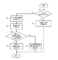
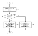
- FIG. 3 is a flowchart showing an example of the operation of the control unit 12 of each charger 1 in the first embodiment.
- the operation illustrated in FIG. 3 is repeatedly performed, for example, every charging control timing or every elapse of a certain time T (for example, 20 minutes).
- the control unit 12 acquires a power limit value (S31).
- the control unit 12 of the slave charger 1 receives the limited power value transmitted from the control unit 12 of the master charger 1 by transmitting a transmission request for the limited power value to the control unit 12 of the master charger 1.
- the power limit value is acquired.
- the control unit 12 obtains the first current value by dividing the limit power value by the voltage output to the power storage device 4 (output voltage of the charger 1) (S32). For example, when the voltage output to the power storage device 4 is 48 [V] and the limit power value is 10 [kW], the control unit 12 calculates 10 [kW] / 48 [V] ⁇ 208 [A]. Thus, 208 [A] is obtained as the first current value. At this time, the outputable current value of the charger 1 is updated based on the first current value and transmitted to the control unit 42 of the power storage device 4.
- the controller 12 determines that the obtained first current value is equal to or greater than the received current command value (S33: No), a current corresponding to the received current command value is output from the charger 1. Thus, the operation of the power supply unit 11 is controlled (S35).
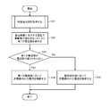
- FIG. 4 is a flowchart showing an example of the operation of the control unit 12 of the master charger 1 in the first embodiment. Note that the operation illustrated in FIG. 4 is repeatedly performed, for example, every charging control timing or every elapse of a certain time T (for example, 20 minutes).
- the control unit 12 of the master charger 1 determines the number of power storage devices 4 to be charged (the power storage device 4 to which power is to be supplied from the charger 1 or the power storage device 4 to which power is supplied from the charger 1). Obtain (S41). For example, the control unit 12 of the master charger 1 is transmitted from the control unit 42 of the power storage device 4 of its own power supply destination and the number of transmission requests for the limit power value transmitted from the control unit 12 of the slave charger 1. The result of adding the number of charging start instructions is the number of power storage devices 4 to be charged.
- control unit 12 of the master charger 1 divides the desired power set by the user arbitrarily by the number of power storage devices 4 to be charged, which is equal to or less than the contract power of the commercial power supply 2 and is set by the user. A value is obtained (S42).
- the contract power of the commercial power supply is set to 60 [kW]
- the desired power is set to 50 Consider the case of [kW].
- the master charger 1A supplies power to the power storage device 4A
- the slave charger 1B supplies power to the power storage device 4B
- the slave charger 1C supplies power to the power storage device 4C
- the slave charger 1D stores power. It is assumed that power is supplied to the device 4D and the slave charger 1E supplies power to the power storage device 4E.
- the voltages output from the chargers 1A to 1E to the power storage devices 4A to 4E are 48 [V], respectively. Further, at a certain charge control timing, the current command value transmitted from the control unit 42 of the power storage device 4A to the control unit 12 of the master charger 1A is 200 [A], and the control unit 42 of the power storage device 4B transmits the slave charger 1B.
- the current command value transmitted to the control unit 12 is 200 [A]
- the current command value transmitted from the control unit 42 of the power storage device 4C to the control unit 12 of the slave charger 1C is 150 [A]
- the slave power storage device 4D The current command value transmitted from the control unit 42 to the control unit 12 of the charger 1D is 100 [A]
- the current command value transmitted from the control unit 42 of the power storage device 4E to the control unit 12 of the slave charger 1E is 50 [A]. A].
- the control unit 12 of the master charger 1A calculates a first current value (208 [A]) by calculating 10 [kW] / 48 [V] ⁇ 208 [A].
- the outputable current value of the charger 1A is updated based on the first current value and transmitted to the control unit 42 of the power storage device 4A.
- the current command value (200 [A]) is determined.
- the first current value (125 [A]) is obtained.
- the output possible current value of the charger 1A is updated to 125 [A] which is the first current value, and is transmitted to the control unit 42 of the power storage device 4A.
- the first current value (125 [A]) is smaller than the current command value (200 [A]) transmitted from the control unit 42 of the power storage device 4A, the first current value (125 The operation of the power supply unit 11 is controlled so that a current corresponding to [A]) is output from the master charger 1A, and the first current value (125 [A]) is set as an outputable current value of the power storage device 4A. It transmits to the control part 42.
- the voltage output to the power storage device 4 increases, the first current value decreases so that the limit power value does not change. Therefore, the voltage output to the power storage device 4 exceeds the predetermined voltage. Even if it becomes, the total of the output power of each charger 1 (total power consumption of each charger 1) can be prevented from exceeding the desired power, and the total output power of each charger 1 is It is possible not to exceed the contract power.
- the control unit 12 of the slave charger 1B calculates the first current value (208 [A]) by calculating 10 [kW] / 48 [V] ⁇ 208 [A], and the first current value (208 [A]) is obtained.
- the current value (208 [A]) is equal to or greater than the current command value (200 [A]) transmitted from the control unit 42 of the power storage device 4B
- the current corresponding to the current command value (200 [A]) Is controlled from the slave charger 1B.
- the outputtable current value of charger 1B is updated based on the first current value and transmitted to control unit 42 of power storage device 4B.
- the control unit 12 of the slave charger 1C calculates the first current value (208 [A]) by calculating 10 [kW] / 48 [V] ⁇ 208 [A], and the first current value (208 [A]) is obtained.
- the current value (208 [A]) is equal to or greater than the current command value (150 [A]) transmitted from the control unit 42 of the power storage device 4C
- the current according to the current command value (150 [A]) Is controlled from the slave charger 1 ⁇ / b> C to control the operation of the power supply unit 11.
- the control unit 12 of the slave charger 1D calculates the first current value (208 [A]) by calculating 10 [kW] / 48 [V] ⁇ 208 [A], and the first current value (208 [A]) is obtained.
- the current value (208 [A]) is equal to or greater than the current command value (100 [A]) transmitted from the control unit 42 of the power storage device 4D, the current corresponding to the current command value (100 [A]) Is controlled from the slave charger 1D.
- the control unit 12 of the slave charger 1E obtains a first current value (208 [A]) by calculating 10 [kW] / 48 [V] ⁇ 208 [A], and the first current value (208 [A]) is obtained.
- the current value (208 [A]) is equal to or greater than the current command value (50 [A]) transmitted from the control unit 42 of the power storage device 4E, the current corresponding to the current command value (50 [A]) Is controlled from the slave charger 1E.
- the controller 12 of the master charger 1A determines that the first current value (208 [A]) is smaller than the current command value (210 [A]) transmitted from the controller 42 of the power storage device 4A.
- the operation of the power supply unit 11 is controlled so that a current corresponding to the first current value (208 [A]) is output from the master charger 1A, and the first current value (208 [A]) is determined. Is output to the control unit 42 of the power storage device 4A as an outputable current value.
- the master charger 1A has the total power value (710 [A] ⁇ 48 [V] ⁇ 34 [kW]) obtained by the sum of the current command values transmitted from the power storage devices 4A to 4E. ) Is smaller than the desired power (50 [kW]), but if the first current value (208 [A]) is smaller than the current command value (210 [A]), the first The current output to power storage device 4A is controlled according to the current value (208 [A]).
- the total of current command values (710 [A]) transmitted from the power storage devices 4A to 4E is the voltage (48 [V]) output to the power storage devices 4A to 4E.
- the first current value ( 208 [A]) is smaller than the current command value (210 [A])
- the current output to the power storage device 4A is controlled according to the first current value (208 [A]).
- the control part 12 of each charger 1 of 1st Example is the restriction
- ⁇ Second embodiment> The control unit 12 of each charger 1 in the second embodiment compares the first current value and the current command value when the total power consumption, which is the sum of the output power of each charger 1, is larger than the desired power.
- the first current value is smaller than the current command value, the current output to the power storage device 4 to be charged (the power storage device 4 of its own power supply destination) is controlled according to the first current value.
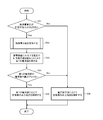
- FIG. 5 is a flowchart showing an example of the operation of the control unit 12 of each charger 1 in the second embodiment.
- the operation illustrated in FIG. 5 is repeatedly performed, for example, every charging control timing or every elapse of a certain time T (for example, 20 minutes).
- control unit 12 determines whether or not the total power consumption is larger than the desired power (S51). For example, the control unit 12 of the master charger 1 sets the total output power of the slave charger 1 indicated in the data transmitted from the control unit 12 of each slave charger 1 as the total power consumption. In addition, the control unit 12 of each slave charger 1 receives data indicating the total power consumption from the control unit 12 of the master charger 1.
- the control unit 12 determines that the total power consumption is larger than the desired power (S51: Yes)
- the control unit 12 obtains the limit power value (S52), and sets the limit power value with the voltage output to the power storage device 4.
- the first current value is obtained by dividing (S53), and it is determined whether or not the first current value is smaller than the current command value (S54).
- movement of the control part 12 of the master charger 1 in S52 is the same as the operation
- the outputable current value of the charger 1 is updated based on the first current value and transmitted to the control unit 42 of the power storage device 4.
- the control unit 12 determines that the first current value is smaller than the current command value (S54: Yes)
- the power source is configured so that a current corresponding to the first current value is output from the charger 1.
- the operation of the unit 11 is controlled (S55).
- control unit 12 determines that the total power consumption is equal to or less than the desired power (S51: No), or determines that the first current value is equal to or greater than the current command value (S54: No). Then, the operation of the power supply unit 11 is controlled so that a current corresponding to the current command value is output from the charger 1 (S56).
- each voltage output from the master charger 1A and the slave charger 1B to the power storage device 4A and the power storage device 4B is set to 50 [V].
- the current command value transmitted from the control unit 42 of the power storage device 4A to the control unit 12 of the master charger 1A is set to 240 [A]
- the control unit 42 of the power storage device 4B sets the slave charger 1B.
- the current command value transmitted to the control unit 12 is 240 [A].
- control unit 12 of the master charger 1A has its own output power (12 [kW]) and the output power (12 [kW]) of the slave charger 1B indicated in the data transmitted from the slave charger 1B. Is obtained as the total power consumption, and data indicating the total power consumption is transmitted to the control unit 12 of the slave charger 1B.
- the outputable current value of the charger 1A is updated based on the first current value and transmitted to the control unit 42 of the power storage device 4A.
- the first current value (200 [A]) is smaller than the current command value (240 [A]) transmitted from the control unit 42 of the power storage device 4A
- the first current value (200 The operation of the power supply unit 11 is controlled so that a current corresponding to [A]) is output from the master charger 1A.
- the control unit 12 of the slave charger 1B determines that the total power consumption (24 [kW]) is larger than the desired power (20 [kW])
- the output possible current value of the charger 1B is updated based on the first current value and transmitted to the control unit 42 of the power storage device 4B.
- the first current value (200 [A]) is smaller than the current command value (240 [A]) transmitted from the control unit 42 of the power storage device 4B
- the first current value (200 The operation of the power supply unit 11 is controlled so that a current corresponding to [A]) is output from the slave charger 1B.
- a charging system including a master charger 1A and a slave charger 1B
- the output power of the master charger 1A is 12 [kW] and the output power of the slave charger 1B is 10 [kW].
- the contract power of the commercial power supply is 25 [kW]
- the desired power is 20 [kW].
- master charger 1A supplies power to power storage device 4A
- slave charger 1B supplies power to power storage device 4B.
- each voltage output from the master charger 1A and the slave charger 1B to the power storage device 4A and the power storage device 4B is set to 50 [V].
- the current command value transmitted from the control unit 42 of the power storage device 4A to the control unit 12 of the master charger 1A is set to 240 [A]
- the control unit 42 of the power storage device 4B sets the slave charger 1B.
- the current command value transmitted to the control unit 12 is 200 [A].
- control unit 12 of the master charger 1A has its own output power (12 [kW]) and the output power of the slave charger 1B (10 [10 [kW]) indicated by the data transmitted from the control unit 12 of the slave charger 1B. kW]) and the total power consumption (22 [kW]) are obtained as total power consumption, and data indicating the total power consumption is transmitted to the control unit 12 of the slave charger 1B.
- the outputable current value of the charger 1A is updated based on the first current value and transmitted to the control unit 42 of the power storage device 4A.
- the first current value (200 [A]) is smaller than the current command value (240 [A]) transmitted from the control unit 42 of the power storage device 4A
- the first current value (200 The operation of the power supply unit 11 is controlled so that a current corresponding to [A]) is output from the master charger 1A.
- the control unit 12 of the slave charger 1B determines that the total power consumption (22 [kW]) is larger than the desired power (20 [kW])
- the output possible current value of the charger 1B is updated based on the first current value and transmitted to the control unit 42 of the power storage device 4B.
- the operation of the power supply unit 11 is controlled such that a current corresponding to the current command value (200 [A]) is output from the slave charger 1B.
- a charging system including a master charger 1A and a slave charger 1B
- the output power of the master charger 1A is 14 [kW] and the output power of the slave charger 1B is 8 [kW].
- the contract power of the commercial power supply is 25 [kW]
- the desired power is 20 [kW].
- master charger 1A supplies power to power storage device 4A
- slave charger 1B supplies power to power storage device 4B.
- each voltage output from the charger 1A and the charger 1B to the power storage device 4A and the power storage device 4B is set to 50 [V].
- the current command value transmitted from the control unit 42 of the power storage device 4A to the control unit 12 of the master charger 1A is set to 280 [A]
- the control unit 42 of the power storage device 4B sets the slave charger 1B.
- the current command value transmitted to the control unit 12 is 160 [A].
- the controller 12 of the master charger 1A has its own output power (14 [kW]) and the output power of the slave charger 1B (8 [8 [kW]) indicated by the data transmitted from the controller 12 of the slave charger 1B. kW]) and the total power consumption (22 [kW]) are obtained as total power consumption, and data indicating the total power consumption is transmitted to the control unit 12 of the slave charger 1B.
- the outputable current value of the charger 1A is updated based on the first current value and transmitted to the control unit 42 of the power storage device 4A.
- the first current value (200 [A]) is smaller than the current command value (280 [A]) transmitted from the control unit 42 of the power storage device 4A
- the first current value (200 The operation of the power supply unit 11 is controlled so that a current corresponding to [A]) is output from the master charger 1A.
- the control unit 12 of the slave charger 1B determines that the total power consumption (22 [kW]) is larger than the desired power (20 [kW])
- the output possible current value of the charger 1B is updated based on the first current value and transmitted to the control unit 42 of the power storage device 4B.
- current command value is the first value. If it is determined that the current is smaller than the current value), the operation of the power supply unit 11 is controlled so that a current corresponding to the current command value (160 [A]) is output from the slave charger 1B.
- the total power consumption (18 [kW]) can be prevented from exceeding the contract power (25 [kW]).
- the total power consumption (18 [kW]) after controlling the current output from the charger 1 to the power storage device 4 according to the first current value is smaller than the desired power (20 [kW]). Even in this case, the current output from the charger 1 to the power storage device 4 is controlled according to the first current value.
- ⁇ Third embodiment> The control unit 12 of each charger 1 in the third embodiment determines whether or not to compare the first current value and the current command value according to the time zone.
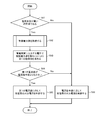
- FIG. 6 is a flowchart showing an example of the operation of the control unit 12 of each charger 1 in the third embodiment. Note that the operation illustrated in FIG. 6 is repeatedly performed, for example, every charging control timing or every elapse of a certain time T (for example, 20 minutes).
- the control unit 12 determines whether or not the current time is a time zone when the electricity rate is high (for example, a time zone of midnight or early morning) (S61). Next, when the control unit 12 determines that the current time is a time zone in which the electricity rate is high (S61: Yes), the control unit 12 acquires a limit power value (S62) and limits the voltage with the voltage output to the power storage device 4.
- the first current value is obtained by dividing the power value (S63), and it is determined whether or not the first current value is smaller than the current command value (S64).
- movement of the control part 12 of the master charger 1 in S62 is the same as the operation
- the control unit 12 determines that the first current value is smaller than the current command value (S64: Yes)
- the power source is configured so that a current corresponding to the first current value is output from the charger 1.
- the operation of the unit 11 is controlled (S65).
- control unit 12 determines that the current time is not a time zone when the electricity rate is high (S61: No), or determines that the first current value is equal to or greater than the current command value (S64). : No), the operation of the power supply unit 11 is controlled so that a current corresponding to the current command value is output from the charger 1 (S66).
- FIG. 7 is a diagram illustrating an example of a change in the total output power of each charger 1 in the third embodiment.
- the time zone when the electricity rate is high is set to 8:00 to 16:00
- the time zone where the electricity rate is not high is set to 0:00 to 8:00 and 16:00 to 24:00.
- the control unit 12 determines that the current time is a time when the electricity rate is high.
- the power supply unit 11 is controlled so that a current corresponding to the first current value is output from the charger 1 while the first current value is determined to be smaller than the current command value. To do.
- the total power value obtained by the sum of the current command values transmitted from the power storage device 4 to be charged exceeds the desired power from 12:00 to 13:00, the total output power of each charger 1 is The desired power can be prevented from exceeding.
- the power (hatched portion) that could not be supplied to the power storage device 4 from 12:00 to 13:00 is supplied to the power storage device 4 from 13:00 to 14:00.
- control unit 12 of each charger 1 in the third embodiment determines whether or not to compare the first current value and the current command value according to the time zone, so that the electricity charge is reduced. Since the total output power of each charger 1 can be suppressed in a high time zone, the electricity bill can be suppressed.
- the control unit 12 of the master charger 1 in the fourth embodiment changes the desired power according to the time zone.
- FIG. 8 is a flowchart showing an example of the operation of the control unit 12 of the master charger 1 in the fourth embodiment. Note that the operation illustrated in FIG. 8 is repeatedly performed, for example, every charging control timing or every elapse of a certain time T (for example, 20 minutes). The operation of the control unit 12 of each charger 1 in the fourth embodiment is the same as the operation shown in FIG. 3 or the operation shown in FIG.
- the control unit 12 of the master charger 1 obtains the number of power storage devices 4 to be charged (S81). Next, when the controller 12 of the master charger 1 determines that the current time is not a time zone when the electricity rate is high (S82: No), the first desired number of power storage devices 4 to be charged is determined. The power limit value is obtained by dividing the power (S83).
- the control part 12 of the master charger 1 judges that the present time is a time slot
- the power limit value is obtained by dividing the second desired power smaller than (S84).
- the 1st and 2nd desired electric power shall be smaller than the contract electric power of the commercial power supply 2, and shall be arbitrarily set by the user.
- FIG. 9 is a diagram illustrating an example of a change in the total output power of each charger 1 in the fourth embodiment.
- the time zone when the electricity rate is high is set to 8:00 to 16:00, and the time zone where the electricity rate is not high is set to 0:00 to 8:00 and 16:00 to 24:00.
- the control unit 12 determines that the first current value is smaller than the current command value, and the power supply so that the current corresponding to the first current value is output from the charger 1. It is assumed that the operation of the unit 11 is controlled.
- the control unit 12 of the master charger 1 determines that the current time is not a time zone when the electricity rate is high, and the number of power storage devices 4 to be charged is Then, the power limit value is obtained by dividing the first desired power.
- the power (shaded portion) that could not be supplied to the power storage device 4 from 17:00 to 18:00 is supplied to the power storage device 4 from 18:00 to 19:00.
- the control unit 12 of the master charger 1 determines that the current time is a time zone when the electricity rate is high, and the charging of the power storage device 4 to be charged is performed.
- the power limit value is determined by dividing the second desired power by the number. Accordingly, even if the total power value obtained by the sum of the current command values transmitted from the power storage device 4 to be charged exceeds the second desired power at 12:00 to 13:00 shown in FIG. The sum of the output powers of 1 may not exceed the second desired power. In the example shown in FIG. 9, the power (shaded portion) that could not be supplied to the power storage device 4 from 12:00 to 13:00 is supplied to the power storage device 4 from 13:00 to 14:00.
- control unit 12 of the master charger 1 in the fourth embodiment changes the desired power according to the time zone, so that it can be compared with the desired power in the time zone where the electricity rate is not high. In addition, it is possible to reduce the desired power in the time zone when the electricity charge is high, and to suppress the electricity charge.
- control unit 12 of each charger 1 in the fourth embodiment is configured such that the total output power of each charger 4 is a desired power (first and second) in all time zones. Desired power), and the total output power of each charger 1 does not exceed the contract power.
- FIG. 10 is a flowchart illustrating an example of the operation of the control unit 12 of each charger 1 in the fifth embodiment. Note that the operation shown in FIG. 10 is repeatedly performed at every charging control timing or every elapse of a fixed time T (for example, 20 minutes).
- control unit 12 determines whether or not the total power consumption is larger than desired power (S101). For example, the control unit 12 of the master charger 1 adds the result of adding its own output power and the output power of the slave charger 1 indicated in the data transmitted from the control unit 12 of the slave charger 1 to the total power consumption. And Further, the control unit 12 of the slave charger 1 receives data indicating the total power consumption transmitted from the control unit 12 of the master charger 1.
- the control unit 12 acquires a power limit value (S102).
- the control part 12 of the master charger 1 acquires a control electric power value by calculation so that it may mention later.
- the control unit 12 of the slave charger 1 acquires the limit power value by receiving data indicating the limit power value transmitted from the control unit 12 of the master charger 1.
- control unit 12 obtains the upper limit current value (first current value) by dividing the limit power value by the voltage (output voltage of the charger 1) output to the power storage device 4 to which the power is supplied. Then, the output possible current value is updated based on the obtained upper limit current value, and the updated output possible current value is transmitted to the control unit 42 of the power storage device 4 of its own power supply destination (S103).
- control unit 12 determines whether or not the upper limit current value obtained in S103 is smaller than the current command value transmitted from the control unit 42 of the power storage device 4 that is the power supply destination of the control unit 12 (S104).
- the control unit 12 determines that the upper limit current value is smaller than the current command value (S104: Yes)
- the power supply unit 11 is configured so that a current corresponding to the upper limit current value is output from its own charger 1. Is controlled (S105).
- control unit 12 determines that the upper limit current value is equal to or greater than the current command value (S104: No)
- the control unit 12 causes the power supply unit 11 to output a current corresponding to the current command value from its own charger 1.
- the operation is controlled (S106).
- the control unit 12 when determining that the total power consumption is equal to or less than the desired power (S101: No), the control unit 12 returns the outputtable current value to the initial value and the outputable current value that has been returned to the initial value. So as to output a current corresponding to the current command value transmitted from the control unit 42 of the power storage device 4 from its own charger 1.
- the operation of the power supply unit 11 is controlled (S106). For example, when the current command value obtained by the control unit 42 of the power storage device 4 is 300 [A], the outputable current value is changed from 200 [A] to 300 [A] by returning the outputable current value to the initial value.
- the current command value transmitted from the control unit 42 of the power storage device 4 to the control unit 12 of the charger 1 also changes from 200 [A].
- the initial value of the output possible current value is the maximum current value that each charger 1 can output.
- the initial value of the output possible current value is determined in advance by the output performance of the power supply unit 11 of each charger 1 and the performance of other components, and is stored in the control unit 12.
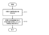
- FIG. 11 is a flowchart showing an example of the operation of the control unit 12 of the master charger 1 in the fifth embodiment. Note that the operation shown in FIG. 11 is repeatedly performed at every charge control timing or every elapse of a certain time T (for example, 20 minutes).
- the control unit 12 of the master charger 1 determines the number of power storage devices 4 to be charged (the power storage device 4 to which power is to be supplied from the charger 1 or the power storage device 4 to which power is supplied from the charger 1). Obtain (S111).
- the control unit 12 of the master charger 1 is transmitted from the control unit 42 of the power storage device 4 of its own power supply destination and the number of transmission requests for the limit power value transmitted from the control unit 12 of the slave charger 1.
- the result of adding the number of charging start instructions is the number of power storage devices 4 to be charged.
- control unit 12 of the master charger 1 obtains a limit power value by dividing desired power arbitrarily set by the user by the number of power storage devices 4 to be charged (S112). Note that the desired power is set to be equal to or lower than the contract power of the commercial power source 2.
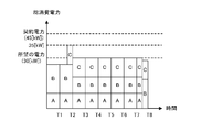
- the contract power of the commercial power source is 45 [kW]
- the desired power is 30 [kW].
- the output voltage of each charger 1 is 50 [V].
- the initial value of the output possible current value of the master charger 1A, the initial value of the output possible current value of the slave charger 1B, and the initial value of the output possible current value of the slave charger 1C are each 300 [A]. .
- the current command value obtained by the control unit 42 of the power storage device 4A that is the power supply destination of the master charger 1A is set to 200 [A]
- the control unit 42 of the power storage device 4B that is the power supply destination of the slave charger 1B is set to 200 [A]
- the current command value obtained by the control unit 42 of the power storage device 4C, which is the power supply destination of the slave charger 1C is 200 [A].
- power is supplied to the power storage device 4C in addition to the power storage device 4A and the power storage device 4B.
- the control unit 12 of the master charger 1A has its own output power (10 [kW]), the output power of the slave charger 1B (15 [kW]), and the output power of the slave charger 1C.
- the total power consumption 25 [kW]
- the desired power 30 [kW]
- a current command transmitted from the control unit 42 of the power storage device 4A The operation of the power supply unit 11 is controlled so that a current corresponding to the value (200 [A]) is output from the own charger 1.
- the control unit 12 of the slave charger 1B determines that the total power consumption (25 [kW]) is equal to or less than the desired power (30 [kW])
- the control unit 42 of the power storage device 4B transmits it.
- the operation of the power supply unit 11 is controlled so that a current corresponding to the current command value (300 [A]) is output from the charger 1 of its own.
- the control unit 12 of the master charger 1A has its own output power (10 [kW]), the output power of the slave charger 1B (15 [kW]), and the output of the slave charger 1C.
- the total power consumption 35 [kW]
- 30 [kW] / 3 [unit] 10
- the power limit value (10 [kW]) is obtained by calculating [kW]
- the upper limit current value 200 [A]
- 10 [kW] / 50 [V] 200 [A].
- control unit 12 of the master charger 1A updates the output possible current value from 200 [A] to 200 [A] based on the upper limit current value (200 [A]), and can output after the update.
- the current value (200 [A]) is transmitted to the control unit 42 of the power storage device 4A.
- control unit 42 of power storage device 4A determines the output possible current value (200 [A]).
- A]) is transmitted as a current command value to the control unit 12 of the master charger 1A.
- control unit 12 of master charger 1A determines that the upper limit current value (200 [A]) is equal to or greater than the current command value (200 [A]) transmitted from control unit 42 of power storage device 4A, current command The operation of the power supply unit 11 is controlled so that a current corresponding to the value (200 [A]) is output from the own charger 1.
- the upper limit current value (200 [A]) is obtained by calculating [A].
- control unit 12 of the slave charger 1B updates the output possible current value from 300 [A] to 200 [A] based on the upper limit current value (200 [A]), and can output after the update.
- the current value (200 [A]) is transmitted to the control unit 42 of the power storage device 4B.
- the control unit 42 of the power storage device 4B determines that the current command value (300 [A]) obtained by itself is equal to or greater than the received outputable current value (200 [A])
- the outputable current value (200 [A]) is determined.
- A]) is transmitted to the control unit 12 of the slave charger 1B as a current command value.
- control unit 12 of slave charger 1B determines that the upper limit current value (200 [A]) is equal to or greater than the current command value (200 [A]) transmitted from control unit 42 of power storage device 4B, current command The operation of the power supply unit 11 is controlled so that a current corresponding to the value (200 [A]) is output from the own charger 1.
- the upper limit current value (200 [A]) is obtained by calculating [A].
- control part 12 of 1 C of slave chargers can update the output possible electric current value from 200 [A] to 200 [A] based on an upper limit electric current value (200 [A]), and the output after the update is possible
- the current value (200 [A]) is transmitted to the control unit 42 of the power storage device 4C.
- the control unit 42 of the power storage device 4C determines that the current command value (200 [A]) obtained by itself is equal to or greater than the received output possible current value (200 [A])
- the output possible current value (200 [A]) is determined.
- A]) is transmitted as a current command value to the control unit 12 of the slave charger 1C.
- control unit 12 of slave charger 1C determines that the upper limit current value (200 [A]) is equal to or greater than the current command value (200 [A]) transmitted from control unit 42 of power storage device 4C, current command The operation of the power supply unit 11 is controlled so that a current corresponding to the value (200 [A]) is output from the own charger 1.
- Device 1B: 10 [kW] 200 [A] ⁇ 50 [V]
- the control unit 12 of the master charger 1A its own output power (10 [kW]), the output power of the slave charger 1B (10 kW), and the output power of the slave charger 1C ( 10 [kW]), when it is determined that the total power consumption (30 [kW]) is equal to or less than the desired power (30 [kW]), the output possible current value (300 [A]) returned to the initial value ) Is transmitted to the control unit 42 of the power storage device 4A.
- the control unit 42 of the power storage device 4A determines that the current command value (200 [A]) obtained by itself is smaller than the received output possible current value (300 [A]), the current command value (200 [A] ]) To the controller 12 of the master charger 1A.
- the control unit 12 of the master charger 1A is configured so that the current corresponding to the current command value (200 [A]) transmitted from the control unit 42 of the power storage device 4A is output from its own charger 1. Control the behavior. Similarly, when the control unit 12 of the slave charger 1B determines that the total power consumption (30 [kW]) is equal to or less than the desired power (30 [kW]) at time T3, the output can be returned to the initial value. The current value (300 [A]) is transmitted to the control unit 42 of the power storage device 4B.
- the output possible current value (300 [A] A]) is transmitted to the control unit 12 of the slave charger 1B as a current command value.
- Control unit 12 of slave charger 1B controls the operation of power supply unit 11 so that a current corresponding to the current command value (300 [A]) transmitted from control unit 42 of power storage device 4B is output from itself.
- the control unit 12 of the slave charger 1C determines that the total power consumption (30 [kW]) is equal to or less than the desired power (30 [kW]) at time T3, the output can be returned to the initial value.
- the current value (300 [A]) is transmitted to the control unit 42 of the power storage device 4C.
- the control unit 42 of the power storage device 4C determines that the current command value (200 [A]) obtained by itself is smaller than the received output possible current value (300 [A])
- the current command value (200 [A] ]) Is transmitted to the control unit 12 of the slave charger 1C.
- Control unit 12 of slave charger 1C controls the operation of power supply unit 11 such that a current corresponding to the current command value (200 [A]) transmitted from control unit 42 of power storage device 4C is output from itself. .
- the control unit 12 of each charger 1 uses the power limit value obtained by dividing the desired power by the number of power storage devices 4 to be charged because the total power consumption is larger than the desired power.
- the output current of the charger 1 can be made equal to or lower than the upper limit current value. If they are the same, the total power consumption can be prevented from exceeding the desired power, and the total power consumption can be prevented from exceeding the contract power.
- control unit 12 of each charger 1 of the fifth embodiment when controlling the output current according to the upper limit current value, if the total power consumption becomes less than the desired power, the output possible current value By returning to the initial value and controlling the output current according to the current command value (ending the control of the output current according to the upper limit current value), the total power consumption is increased to the total power consumption before suppression. Therefore, compared with the case where the output power of each charger 1 is continuously suppressed, the charging rate can be increased and the charging time can be suppressed from being extended.
- FIG. 13 is a flowchart showing an example of the operation of the control unit 12 of each charger 1 in the sixth embodiment. Note that the operation shown in FIG. 13 is repeatedly performed at every charging control timing or every elapse of a fixed time T (for example, 20 minutes).
- the control unit 12 determines that the total power consumption is larger than the desired power (S131: Yes) or determines that the total power consumption is equal to or less than the desired power (S131: No).
- the power limit value is acquired (S133).
- the control unit 12 of the master charger 1 obtains the limit power value by executing the operation shown in FIG. 11, for example.
- control unit 12 obtains the upper limit current value by dividing the limit power value by the voltage (output voltage of the charger 1) output to the power storage device 4 that is the power supply destination of the control unit 12, and the obtained upper limit current value.
- the output possible current value is updated based on the information, and the updated output possible current value is transmitted to the control unit 42 of the power storage device 4 of its own power supply destination (S134).
- the control unit 12 determines whether or not the upper limit current value obtained in S134 is smaller than the current command value transmitted from the control unit 42 of the power storage device 4 of its own power supply destination (S135).
- the control unit 12 determines that the upper limit current value is smaller than the current command value (S135: Yes)
- the peak cut flag corresponding to itself is changed from the OFF state to the ON state and transmitted to the other charger 1 (S137).
- control unit 12 determines that the upper limit current value is equal to or greater than the current command value (S135: No)
- the control unit 12 operates the power supply unit 11 so that a current corresponding to the current command value is output from the charger 1. Control is performed (S138).
- control unit 12 determines that the total power consumption is equal to or less than the desired power (S131: No), and determines that there is no charger 1 having an on-state peak cut flag (S132: No).
- the outputtable current value is returned to the initial value, and the outputtable current value returned to the initial value is transmitted to the control unit 42 of the power storage device 4 that is the power supply destination (S139), and the control unit of the power storage device 4 is transmitted.
- the operation of the power supply unit 11 is controlled such that a current corresponding to the current command value transmitted from 42 is output from its own charger 1 (S138).
- the peak cut flag in the on state is reset to the off state when the charging process of the corresponding charger 1 is completed.
- the contract power of the commercial power source is 45 [kW]
- the desired power is 30 [kW].
- the output voltage of each charger 1 is 50 [V].
- the initial value of the output possible current value of the master charger 1A, the initial value of the output possible current value of the slave charger 1B, and the initial value of the output possible current value of the slave charger 1C are each 300 [A]. .
- the current command value obtained by the control unit 42 of the power storage device 4A that is the power supply destination of the master charger 1A is set to 200 [A]
- the control unit 42 of the power storage device 4B that is the power supply destination of the slave charger 1B is the power supply destination of the slave charger 1B.
- the obtained current command value is 300 [A]
- the current command value obtained by the control unit 42 of the power storage device 4C, which is the power supply destination of the slave charger 1C is 200 [A].
- power is supplied to the power storage device 4C in addition to the power storage device 4A and the power storage device 4B.
- each charger 1 is performed by each charger 1 at time T1 and time T2 in FIG. This is the same as the current control process of the control unit 12. Further, at time T2 in FIG. 14, the peak cut flag corresponding to the master charger 1A remains in the OFF state, the peak cut flag corresponding to the slave charger 1B changes from the OFF state to the ON state, and the slave charger 1C. The peak cut flag corresponding to is left in the off state.
- the current value (200 [A]) is transmitted to the control unit 42 of the power storage device 4A.
- control unit 42 of power storage device 4A determines the output possible current value (200 [A]).
- A]) is transmitted as a current command value to the control unit 12 of the master charger 1A.
- control unit 12 of master charger 1A determines that the upper limit current value (200 [A]) is equal to or greater than the current command value (200 [A]) transmitted from control unit 42 of power storage device 4A, current command The operation of the power supply unit 11 is controlled so that a current corresponding to the value (200 [A]) is output from the own charger 1.
- the control unit 42 of the power storage device 4B determines that the current command value (300 [A]) obtained by itself is equal to or greater than the received outputable current value (200 [A]), the outputable current value (200 [A]) is determined. A]) is transmitted to the control unit 12 of the slave charger 1B as a current command value.
- the control unit of slave charger 1B determines that the upper limit current value (200 [A]) is equal to or greater than the current command value (200 [A]) transmitted from control unit 42 of power storage device 4B, the current command value
- the operation of the power supply unit 11 is controlled so that a current corresponding to (200 [A]) is output from the charger 1 of itself.
- the control unit 42 of the power storage device 4C determines that the current command value (200 [A]) obtained by itself is equal to or greater than the received output possible current value (200 [A])
- the output possible current value (200 [A]) is determined.
- A]) is transmitted as a current command value to the control unit 12 of the slave charger 1C.
- the control unit of slave charger 1C determines that the upper limit current value (200 [A]) is equal to or greater than the current command value (200 [A]) transmitted from control unit 42 of power storage device 4C, the current command value
- the operation of the power supply unit 11 is controlled so that a current corresponding to (200 [A]) is output from the charger 1 of itself.
- the same charging control as that at time T3 is repeated, and the total power consumption at time T4 to T7 is the same as the total power consumption at time T3 (30 [kW]). That is, in the sixth embodiment, when there is at least one charger 1 having an on-state peak cut flag, the total power consumption (30 [kW]) is set to a desired value until the charging process of the charger 1 is completed. The power can be kept below the power (30 [kW]).
- the total power consumption is larger than the desired power, and the limit power value obtained by dividing the desired power by the number of power storage devices 4 to be charged is stored.
- the output current of the charger 1 can be made lower than the upper limit current value.
- control part 12 of each charger 1 of 6th Example is a case where the total power consumption becomes below desired power when controlling the output current according to the upper limit current value, and the upper limit current.
- the output current is continuously controlled according to the upper limit current value (the control of the output current according to the upper limit current value is not terminated). Therefore, the total power consumption can be continuously suppressed, and the total power consumption can be prevented from rising to the total power consumption before the suppression.
- the charger 1 compares the first current value with the current command value and the first current value is smaller than the current command value, the output current is controlled according to the first current value.
- the current command value is 240 [A]
- the actual current is the first current value, for example, 200 [A].
- the current command value is changed so that the power storage device 4 becomes equal to or less than the outputable current value based on the first current value sent from the charger 1. It is possible to suppress an increase in the difference between the value and the actual current and prevent an error from being determined.
Landscapes
- Engineering & Computer Science (AREA)
- Power Engineering (AREA)
- Charge And Discharge Circuits For Batteries Or The Like (AREA)
- Secondary Cells (AREA)
Abstract
充電する蓄電装置4の数で所望の電力を割った制限電力値によって求められる第1の電流値と、充電する蓄電装置4から充電器1に送信される電流指令値とを比較し、第1の電流値が電流指令値よりも小さい場合、第1の電流値に応じて、充電する蓄電装置3に出力する電流を制御し、第1の電流値が電流指令値以上である場合、電流指令値に応じて、充電する蓄電装置4に出力する電流を制御する。
Description
本発明は、充電器から蓄電装置に出力される電流の制御に関する。
例えば、蓄電装置に備えられる電池を鉛電池からリチウムイオン電池に変更する場合、充電レート(電池を1時間で満充電にするときに電池に流れる電流)が大きくなるため、充電器から蓄電装置に出力される電力が大きくなる。
また、1つの商用電源から供給される電力を複数の充電器に分配し、各充電器がそれぞれ蓄電装置に備えられる電池を充電する場合、各充電器の出力電力の合計が商用電源の契約電力や契約電力以下に設定される所望の電力を超えないように、各充電器の出力電力を抑えることが望まれている。例えば、特許文献1又は特許文献2参照。
本発明は、各充電器の出力電力の合計が所望の電力を超えないようにすることが可能な充電器、電流制御方法、及び充電システムを提供することを目的とする。
実施形態の充電器は、充電する蓄電装置の数で所望の電力を割った電力値によって求められる第1の電流値と、充電する蓄電装置からの電流指令値とを比較し、第1の電流値が電流指令値よりも小さい場合、第1の電流値に応じて、充電する蓄電装置に出力する電流を制御する。
本発明によれば、各充電器の出力電力の合計が所望の電力を超えないようにすることができる。
図1は、実施形態の充電器を含む充電システムの一例を示す図である。
図1に示す充電システムは、複数の充電器1を備える。複数の充電器1のうち、制限電力値を求める充電器1をマスター充電器1とし、他の充電器1をスレーブ充電器1とする。
図1に示す充電システムは、複数の充電器1を備える。複数の充電器1のうち、制限電力値を求める充電器1をマスター充電器1とし、他の充電器1をスレーブ充電器1とする。
各充電器1は、商用電源2から供給される電力を用いて、電動フォークリフトやプラグインハイブリッド車などの車両3に搭載される蓄電装置4に電力を供給する。また、各充電器1は、電源部11及び制御部12を備える。
電源部11は、例えば、AC/DCコンバータにより構成され、商用電源2から供給される交流の電力を直流の電力に変換する。また、電源部11は、商用電源2の出力電圧を所定の電圧に変換する。
制御部12は、自身の電力供給先の蓄電装置4から送信される電流指令値などに応じた電流が電源部11から出力されるように電源部11の動作を制御する。また、各制御部12は通信線13を介して環状に接続されている。なお、各制御部12は、バス型のネットワークに接続されていてもよい。マスター充電器1の制御部12は制限電力値をスレーブ充電器1の制御部12に送信する。また、各制御部12は、制限電力値に基づいて、第1の電流値(電源部11の上限電流値)を求める。また、各制御部12は、第1の電流値をもとに電源部11の出力可能電流値を更新し、その更新後の出力可能電流値を自身の電力供給先の蓄電装置4に送信する。また、各制御部12は、第1の電流値と電流指令値とを比較し、第1の電流値が電流指令値よりも小さい場合、第1の電流値に応じて、充電する蓄電装置4(自身の電力供給先の蓄電装置4)に出力する電流を制御する。また、各制御部12は、第1の電流値に応じて、充電する蓄電装置4に出力する電流を制御しているときに各充電器1の出力電力の合計である総消費電力が所望の電力以下になった場合、「第1の電流値に応じて、充電する蓄電装置4に出力する電流を制御すること」を終了する。また、制御部12は、例えば、CPU(Central Processing Unit)、マルチコアCPU、又はプログラマブルなディバイス(FPGA(Field Programmable Gate Array)やPLD(Programmable Logic Device)など)により構成される。
蓄電装置4は、電池41及び制御部42を備える。
電池41は、例えば、リチウムイオン電池又はニッケル水素電池などの二次電池やキャパシタにより構成され、車両3に搭載される走行用モータや電装機器などに電力を供給する。なお、電池41の定格電圧は、例えば、24[V]、48[V]、又は80[V]が考えられる。
電池41は、例えば、リチウムイオン電池又はニッケル水素電池などの二次電池やキャパシタにより構成され、車両3に搭載される走行用モータや電装機器などに電力を供給する。なお、電池41の定格電圧は、例えば、24[V]、48[V]、又は80[V]が考えられる。
制御部42は、電池41の電圧やSOC(State Of Charge:満充電時の電池41の容量に対する現在の電池41の容量の割合)などに基づいて電流指令値を求め、自身の電力供給元の充電器1の制御部12に送信する。例えば、制御部42は、充電開始から電池41の電圧が所定電圧に達するまでのCC(Constant Current)充電期間において、電池41に流れる充電電流が予め決められた一定値になるように電流指令値を制御する。また、制御部42は、電池41の電圧が所定電圧に達した後のCV(Constant Voltage)充電期間において、電池41の電圧をほぼ一定に保ちながら充電電流が終了電流まで徐々に小さくなるように電流指令値を制御する。また、制御部42は、求めた電流指令値及び自身の電力供給元の充電器1の制御部12から送信される出力可能電流値のうちの小さい方を新たな電流指令値として自身の電力供給元の充電器1の制御部12に送信する。なお、制御部42は、例えば、CPU、マルチコアCPU、又はプログラマブルなディバイスにより構成される。
図2は、蓄電装置4の制御部42の動作の一例を示すフローチャートである。なお、図2に示す動作は、例えば、充電制御タイミング毎、または、一定時間T(例えば、20分)経過毎に繰り返し行われるものとする。
まず、制御部42は、電池41のSOCが所望のSOCよりも小さいと判断すると(S21:No)、自身の電力供給元の充電器1の制御部12から送信される出力可能電流値を受信し(S22)、電池41の電圧やSOCなどに基づいて電流指令値を求める(S23)。なお、制御部42は、電池41の充電が終了していないと判断すると、自身の電力供給元の充電器1の制御部12から送信される出力可能電流値を受信し、電池41の電圧やSOCなどに基づいて電流指令値を求めるように構成してもよい。このように構成する場合、例えば、制御部42は、CV充電期間において、電池41に流れる充電電流が終了電流になっていない場合、電池41の充電が終了していないと判断する。
次に、制御部42は、求めた電流指令値が、受信した出力可能電流値よりも小さいと判断すると(S24:Yes)、その求めた電流指令値を自身の電力供給元の充電器1の制御部12へ送信する(S25)。
また、制御部42は、求めた電流指令値が、受信した出力可能電流値以上であると判断すると(S24:No)、受信した出力可能電流値を電流指令値として自身の電力供給元の充電器1の制御部12に送信する(S26)。
また、制御部42は、電池41のSOCが所望のSOC以上であると判断すると(S21:Yes)、充電終了指示を自身の電力供給元の充電器1の制御部12へ送信し電池41の充電処理を終了する(S27)。なお、制御部42は、電池41の充電が終了したと判断すると、充電終了指示を自身の電力供給元の充電器1の制御部12へ送信し電池41の充電処理を終了するように構成してもよい。このように構成する場合、例えば、制御部42は、CV充電期間において、電池41に流れる充電電流が終了電流になった場合、電池41の充電が終了したと判断する。
<第1実施例>
図3は、第1実施例における各充電器1の制御部12の動作の一例を示すフローチャートである。なお、図3に示す動作は、例えば、充電制御タイミング毎、または、一定時間T(例えば、20分)経過毎に繰り返し行われるものとする。
図3は、第1実施例における各充電器1の制御部12の動作の一例を示すフローチャートである。なお、図3に示す動作は、例えば、充電制御タイミング毎、または、一定時間T(例えば、20分)経過毎に繰り返し行われるものとする。
まず、制御部12は、制限電力値を取得する(S31)。例えば、スレーブ充電器1の制御部12は、制限電力値の送信要求をマスター充電器1の制御部12に送信することでマスター充電器1の制御部12から送信される制限電力値を受信することにより、制限電力値を取得する。
次に、制御部12は、蓄電装置4に出力する電圧(充電器1の出力電圧)で制限電力値を割ることにより第1の電流値を求める(S32)。例えば、蓄電装置4に出力する電圧を48[V]とし、制限電力値を10[kW]とする場合、制御部12は、10[kW]/48[V]≒208[A]を計算することにより、第1の電流値として208[A]を求める。このとき、第1の電流値をもとに充電器1の出力可能電流値を更新して、蓄電装置4の制御部42に送信する。
次に、制御部12は、求めた第1の電流値が、受信した電流指令値よりも小さいと判断する場合(S33:Yes)、第1の電流値に応じた電流が充電器1から出力されるように電源部11の動作を制御する(S34)。
また、制御部12は、求めた第1の電流値が、受信した電流指令値以上であると判断する場合(S33:No)、受信した電流指令値に応じた電流が充電器1から出力されるように電源部11の動作を制御する(S35)。
図4は、第1実施例におけるマスター充電器1の制御部12の動作の一例を示すフローチャートである。なお、図4に示す動作は、例えば、充電制御タイミング毎、または、一定時間T(例えば、20分)経過毎に繰り返し行われるものとする。
まず、マスター充電器1の制御部12は、充電する蓄電装置4(充電器1から電力が供給される予定の蓄電装置4や充電器1から電力が供給されている蓄電装置4)の数を求める(S41)。例えば、マスター充電器1の制御部12は、スレーブ充電器1の制御部12から送信される制限電力値の送信要求の数と、自身の電力供給先の蓄電装置4の制御部42から送信される充電開始指示の数とを加算した結果を、充電する蓄電装置4の数とする。
次に、マスター充電器1の制御部12は、充電する蓄電装置4の数で、商用電源2の契約電力以下で、かつ、ユーザにより任意に設定される所望の電力を割ることにより、制限電力値を求める(S42)。
例えば、マスター充電器1A、スレーブ充電器1B、スレーブ充電器1C、スレーブ充電器1D、及びスレーブ充電器1Eを備える充電システムにおいて、商用電源の契約電力を60[kW]とし、所望の電力を50[kW]とする場合を考える。
また、マスター充電器1Aは蓄電装置4Aに電力を供給し、スレーブ充電器1Bは蓄電装置4Bに電力を供給し、スレーブ充電器1Cは蓄電装置4Cに電力を供給し、スレーブ充電器1Dは蓄電装置4Dに電力を供給し、スレーブ充電器1Eは蓄電装置4Eに電力を供給しているものとする。
また、充電器1A~1Eから蓄電装置4A~4Eに出力する各電圧をそれぞれ48[V]とする。
また、ある充電制御タイミングにおいて、蓄電装置4Aの制御部42からマスター充電器1Aの制御部12に送信される電流指令値が200[A]、蓄電装置4Bの制御部42からスレーブ充電器1Bの制御部12に送信される電流指令値が200[A]、蓄電装置4Cの制御部42からスレーブ充電器1Cの制御部12に送信される電流指令値が150[A]、スレーブ蓄電装置4Dの制御部42から充電器1Dの制御部12に送信される電流指令値が100[A]、蓄電装置4Eの制御部42からスレーブ充電器1Eの制御部12に送信される電流指令値が50[A]とする。
また、ある充電制御タイミングにおいて、蓄電装置4Aの制御部42からマスター充電器1Aの制御部12に送信される電流指令値が200[A]、蓄電装置4Bの制御部42からスレーブ充電器1Bの制御部12に送信される電流指令値が200[A]、蓄電装置4Cの制御部42からスレーブ充電器1Cの制御部12に送信される電流指令値が150[A]、スレーブ蓄電装置4Dの制御部42から充電器1Dの制御部12に送信される電流指令値が100[A]、蓄電装置4Eの制御部42からスレーブ充電器1Eの制御部12に送信される電流指令値が50[A]とする。
このとき、まず、マスター充電器1Aの制御部12は、50[kW]/5[台]=10[kW]を計算することにより、制限電力値(10[kW])を求め、スレーブ充電器1B~1Eに送信する。
次に、マスター充電器1Aの制御部12は、10[kW]/48[V]≒208[A]を計算することにより、第1の電流値(208[A])を求める。このとき、第1の電流値をもとに充電器1Aの出力可能電流値を更新して、蓄電装置4Aの制御部42に送信する。そして、その第1の電流値(208[A])が、蓄電装置4Aの制御部42から送信される電流指令値(200[A])以上であると判断すると、電流指令値(200[A])に応じた電流がマスター充電器1Aから出力されるように電源部11の動作を制御する。なお、蓄電装置4に出力する電圧が48[V]から80[V]に変化した場合、マスター充電器1Aの制御部12は、10[kW]/80[V]=125[A]を計算することにより、第1の電流値(125[A])を求める。このとき、充電器1Aの出力可能電流値を第1の電流値である125[A]に更新して、蓄電装置4Aの制御部42に送信する。そして、その第1の電流値(125[A])が、蓄電装置4Aの制御部42から送信される電流指令値(200[A])よりも小さいと判断すると、第1の電流値(125[A])に応じた電流がマスター充電器1Aから出力されるように電源部11の動作を制御するとともに、第1の電流値(125[A])を出力可能電流値として蓄電装置4Aの制御部42に送信する。このように、蓄電装置4に出力する電圧が大きくなると、制限電力値が変化しないように、第1の電流値が小さくなるため、蓄電装置4に出力する電圧が予め決められた電圧よりも大きくなってしまっても、各充電器1の出力電力の合計(各充電器1の消費電力の総和)が所望の電力を超えないようにすることができ、各充電器1の出力電力の合計が契約電力を超えないようにすることができる。
また、スレーブ充電器1Bの制御部12は、10[kW]/48[V]≒208[A]を計算することにより、第1の電流値(208[A])を求め、その第1の電流値(208[A])が、蓄電装置4Bの制御部42から送信される電流指令値(200[A])以上であると判断すると、電流指令値(200[A])に応じた電流がスレーブ充電器1Bから出力されるように電源部11の動作を制御する。なお、第1の電流値を求めたときに、第1の電流値をもとに充電器1Bの出力可能電流値を更新して、蓄電装置4Bの制御部42に送信する。
また、スレーブ充電器1Cの制御部12は、10[kW]/48[V]≒208[A]を計算することにより、第1の電流値(208[A])を求め、その第1の電流値(208[A])が、蓄電装置4Cの制御部42から送信される電流指令値(150[A])以上であると判断すると、電流指令値(150[A])に応じた電流がスレーブ充電器1Cから出力されるように電源部11の動作を制御する。
また、スレーブ充電器1Dの制御部12は、10[kW]/48[V]≒208[A]を計算することにより、第1の電流値(208[A])を求め、その第1の電流値(208[A])が、蓄電装置4Dの制御部42から送信される電流指令値(100[A])以上であると判断すると、電流指令値(100[A])に応じた電流がスレーブ充電器1Dから出力されるように電源部11の動作を制御する。
また、スレーブ充電器1Eの制御部12は、10[kW]/48[V]≒208[A]を計算することにより、第1の電流値(208[A])を求め、その第1の電流値(208[A])が、蓄電装置4Eの制御部42から送信される電流指令値(50[A])以上であると判断すると、電流指令値(50[A])に応じた電流がスレーブ充電器1Eから出力されるように電源部11の動作を制御する。
次に、蓄電装置4Aの制御部42から送信される電流指令値が200[A]から210[A]に大きくなる場合を考える。なお、蓄電装置4B~4Eから送信される電流指令値は変化しないものとする。また、電流指令値の合計(210[A]+200[A]+150[A]+100[A]+50[A]=710[A])と蓄電装置4A~4Eに出力する各電圧(48[V])とを乗算することによって求められる総電力値を、710[A]×48[V]≒34[kW]とする。
この場合、マスター充電器1Aの制御部12は、第1の電流値(208[A])が、蓄電装置4Aの制御部42から送信される電流指令値(210[A])よりも小さいと判断し、第1の電流値(208[A])に応じた電流がマスター充電器1Aから出力されるように電源部11の動作を制御するとともに、第1の電流値(208[A])を出力可能電流値として蓄電装置4Aの制御部42に送信する。
スレーブ充電器1B~1Eの制御部12の動作は、上述のスレーブ充電器1B~1Eの制御部12の動作と同様である。
このように、第1実施例のマスター充電器1Aは、蓄電装置4A~4Eから送信される電流指令値の合計によって求められる総電力値(710[A]×48[V]≒34[kW])が、所望の電力(50[kW])よりも小さい場合であっても、第1の電流値(208[A])が電流指令値(210[A])よりも小さい場合、第1の電流値(208[A])に応じて、蓄電装置4Aに出力する電流を制御する。
このように、第1実施例のマスター充電器1Aは、蓄電装置4A~4Eから送信される電流指令値の合計によって求められる総電力値(710[A]×48[V]≒34[kW])が、所望の電力(50[kW])よりも小さい場合であっても、第1の電流値(208[A])が電流指令値(210[A])よりも小さい場合、第1の電流値(208[A])に応じて、蓄電装置4Aに出力する電流を制御する。
言い換えると、第1実施例のマスター充電器1Aは、蓄電装置4A~4Eから送信される電流指令値の合計(710[A])が、蓄電装置4A~4Eに出力する電圧(48[V])で所望の電力(50[kW])を割った第2の電流値(50[kW]/48[V]≒1041[A])よりも小さい場合であっても、第1の電流値(208[A])が電流指令値(210[A])よりも小さい場合、第1の電流値(208[A])に応じて、蓄電装置4Aに出力する電流を制御する。
これにより、第1実施例の各充電器1の制御部12は、電流指令値が大きくなっても、充電器1の出力電流を、充電する蓄電装置4の数で所望の電力を割った制限電力値を蓄電装置4に出力する電圧で割ることによって求められる第1の電流値以下にすることができるため、各充電器1の出力電圧が互いに同じ場合、各充電器4の出力電力の合計が所望の電力を超えないようにすることができ、各充電器1の出力電力の合計が契約電力を超えないようにすることができる。
<第2実施例>
第2実施例における各充電器1の制御部12は、各充電器1の出力電力の合計である総消費電力が所望の電力よりも大きい場合、第1の電流値と電流指令値とを比較し、第1の電流値が電流指令値よりも小さい場合、第1の電流値に応じて、充電する蓄電装置4(自身の電力供給先の蓄電装置4)に出力する電流を制御する。
第2実施例における各充電器1の制御部12は、各充電器1の出力電力の合計である総消費電力が所望の電力よりも大きい場合、第1の電流値と電流指令値とを比較し、第1の電流値が電流指令値よりも小さい場合、第1の電流値に応じて、充電する蓄電装置4(自身の電力供給先の蓄電装置4)に出力する電流を制御する。
図5は、第2実施例における各充電器1の制御部12の動作の一例を示すフローチャートである。なお、図5に示す動作は、例えば、充電制御タイミング毎、または、一定時間T(例えば、20分)経過毎に繰り返し行われるものとする。
まず、制御部12は、総消費電力が所望の電力よりも大きいか否かを判断する(S51)。例えば、マスター充電器1の制御部12は、各スレーブ充電器1の制御部12から送信されるデータに示されるスレーブ充電器1の出力電力の総和を総消費電力とする。また、各スレーブ充電器1の制御部12は、マスター充電器1の制御部12から総消費電力を示すデータを受信する。
次に、制御部12は、総消費電力が所望の電力よりも大きいと判断する場合(S51:Yes)、制限電力値を取得し(S52)、蓄電装置4に出力する電圧で制限電力値を割ることにより第1の電流値を求め(S53)、第1の電流値が電流指令値よりも小さいか否かを判断する(S54)。なお、S52におけるマスター充電器1の制御部12の動作は、例えば、図4に示す動作と同様とする。また、S53で、第1の電流値をもとに充電器1の出力可能電流値を更新して、蓄電装置4の制御部42に送信する。
次に、制御部12は、第1の電流値が電流指令値よりも小さいと判断する場合(S54:Yes)、第1の電流値に応じた電流が充電器1から出力されるように電源部11の動作を制御する(S55)。
また、制御部12は、総消費電力が所望の電力以下であると判断する場合(S51:No)、又は、第1の電流値が電流指令値以上であると判断する場合(S54:No)、電流指令値に応じた電流が充電器1から出力されるように電源部11の動作を制御する(S56)。
例えば、マスター充電器1A及びスレーブ充電器1Bを備える充電システムにおいて、マスター充電器1Aの出力電力を12[kW]とし、スレーブ充電器1Bの出力電力を12[kW]とする場合を考える。なお、商用電源の契約電力を25[kW]とし、所望の電力を20[kW]とする。また、マスター充電器1Aは蓄電装置4Aに電力を供給し、スレーブ充電器1Bは蓄電装置4Bに電力を供給しているものとする。また、マスター充電器1A及びスレーブ充電器1Bから蓄電装置4A及び蓄電装置4Bに出力する各電圧をそれぞれ50[V]とする。また、ある充電制御タイミングにおいて、蓄電装置4Aの制御部42からマスター充電器1Aの制御部12に送信される電流指令値を240[A]とし、蓄電装置4Bの制御部42からスレーブ充電器1Bの制御部12に送信される電流指令値を240[A]とする。
まず、マスター充電器1Aの制御部12は、自身の出力電力(12[kW])と、スレーブ充電器1Bから送信されるデータに示されるスレーブ充電器1Bの出力電力(12[kW])との総和(24[kW])を総消費電力として求め、その総消費電力を示すデータをスレーブ充電器1Bの制御部12に送信する。
次に、マスター充電器1の制御部12は、総消費電力(24[kW])が所望の電力(20[kW])よりも大きいと判断すると、20[kW]/2[台]=10[kW]を計算することにより、制限電力値(10[kW])を求め、その制限電力値を示すデータをスレーブ充電器1Bに送信する。
次に、マスター充電器1Aの制御部12は、10[kW]/50[V]=200[A]を計算することにより、第1の電流値(200[A])を求める。このとき、第1の電流値をもとに充電器1Aの出力可能電流値を更新して、蓄電装置4Aの制御部42に送信する。そして、その第1の電流値(200[A])が、蓄電装置4Aの制御部42から送信される電流指令値(240[A])よりも小さいと判断すると、第1の電流値(200[A])に応じた電流がマスター充電器1Aから出力されるように電源部11の動作を制御する。
また、スレーブ充電器1Bの制御部12は、総消費電力(24[kW])が所望の電力(20[kW])よりも大きいと判断すると、10[kW]/50[V]=200[A]を計算することにより、第1の電流値(200[A])を求める。このとき、第1の電流値をもとに充電器1Bの出力可能電流値を更新して、蓄電装置4Bの制御部42に送信する。そして、その第1の電流値(200[A])が、蓄電装置4Bの制御部42から送信される電流指令値(240[A])よりも小さいと判断すると、第1の電流値(200[A])に応じた電流がスレーブ充電器1Bから出力されるように電源部11の動作を制御する。
これにより、マスター充電器1A及びスレーブ充電器1Bのそれぞれの出力電力が10[kW](=200[A]×50[V])になり、総消費電力が20[kW](=10[kW]+10[kW])になるため、総消費電力(20[kW])が所望の電力(20[kW])を超えないようにすることができ、総消費電力(20[kW])が契約電力(25[kW])を超えないようにすることができる。
また、例えば、マスター充電器1A及びスレーブ充電器1Bを備える充電システムにおいて、マスター充電器1Aの出力電力を12[kW]とし、スレーブ充電器1Bの出力電力を10[kW]とする場合を考える。なお、商用電源の契約電力を25[kW]とし、所望の電力を20[kW]とする。また、マスター充電器1Aは蓄電装置4Aに電力を供給し、スレーブ充電器1Bは蓄電装置4Bに電力を供給しているものとする。また、マスター充電器1A及びスレーブ充電器1Bから蓄電装置4A及び蓄電装置4Bに出力する各電圧をそれぞれ50[V]とする。また、ある充電制御タイミングにおいて、蓄電装置4Aの制御部42からマスター充電器1Aの制御部12に送信される電流指令値を240[A]とし、蓄電装置4Bの制御部42からスレーブ充電器1Bの制御部12に送信される電流指令値を200[A]とする。
まず、マスター充電器1Aの制御部12は、自身の出力電力(12[kW])と、スレーブ充電器1Bの制御部12から送信されるデータに示されるスレーブ充電器1Bの出力電力(10[kW])との総和(22[kW])を総消費電力として求め、その総消費電力を示すデータをスレーブ充電器1Bの制御部12に送信する。
次に、マスター充電器1の制御部12は、総消費電力(22[kW])が所望の電力(20[kW])よりも大きいと判断すると、20[kW]/2[台]=10[kW]を計算することにより、制限電力値(10[kW])を求め、その制限電力値を示すデータをスレーブ充電器1Bに送信する。
次に、マスター充電器1Aの制御部12は、10[kW]/50[V]=200[A]を計算することにより、第1の電流値(200[A])を求める。このとき、第1の電流値をもとに充電器1Aの出力可能電流値を更新して、蓄電装置4Aの制御部42に送信する。そして、その第1の電流値(200[A])が、蓄電装置4Aの制御部42から送信される電流指令値(240[A])よりも小さいと判断すると、第1の電流値(200[A])に応じた電流がマスター充電器1Aから出力されるように電源部11の動作を制御する。
また、スレーブ充電器1Bの制御部12は、総消費電力(22[kW])が所望の電力(20[kW])よりも大きいと判断すると、10[kW]/50[V]=200[A]を計算することにより、第1の電流値(200[A])を求める。このとき、第1の電流値をもとに充電器1Bの出力可能電流値を更新して、蓄電装置4Bの制御部42に送信する。そして、その第1の電流値(200[A])が、蓄電装置4Bの制御部42から送信される電流指令値(200[A])以上であると判断すると(第1の電流値が電流指令値と同じであると判断すると)、電流指令値(200[A])に応じた電流がスレーブ充電器1Bから出力されるように電源部11の動作を制御する。
これにより、マスター充電器1A及びスレーブ充電器1Bのそれぞれの出力電力が10[kW](=200[A]×50[V])になり、総消費電力が20[kW](=10[kW]+10[kW])になるため、総消費電力(20[kW])が所望の電力(20[kW])を超えないようにすることができ、総消費電力(20[kW])が契約電力(25[kW])を超えないようにすることができる。
また、例えば、マスター充電器1A及びスレーブ充電器1Bを備える充電システムにおいて、マスター充電器1Aの出力電力を14[kW]とし、スレーブ充電器1Bの出力電力を8[kW]とする場合を考える。なお、商用電源の契約電力を25[kW]とし、所望の電力を20[kW]とする。また、マスター充電器1Aは蓄電装置4Aに電力を供給し、スレーブ充電器1Bは蓄電装置4Bに電力を供給しているものとする。また、充電器1A及び充電器1Bから蓄電装置4A及び蓄電装置4Bに出力する各電圧をそれぞれ50[V]とする。また、ある充電制御タイミングにおいて、蓄電装置4Aの制御部42からマスター充電器1Aの制御部12に送信される電流指令値を280[A]とし、蓄電装置4Bの制御部42からスレーブ充電器1Bの制御部12に送信される電流指令値を160[A]とする。
まず、マスター充電器1Aの制御部12は、自身の出力電力(14[kW])と、スレーブ充電器1Bの制御部12から送信されるデータに示されるスレーブ充電器1Bの出力電力(8[kW])との総和(22[kW])を総消費電力として求め、その総消費電力を示すデータをスレーブ充電器1Bの制御部12に送信する。
次に、マスター充電器1Aの制御部12は、総消費電力(22[kW])が所望の電力(20[kW])よりも大きいと判断すると、20[kW]/2[台]=10[kW]を計算することにより、制限電力値(10[kW])を求め、その制限電力値を示すデータをスレーブ充電器1Bに送信する。
次に、マスター充電器1Aの制御部12は、10[kW]/50[V]=200[A]を計算することにより、第1の電流値(200[A])を求める。このとき、第1の電流値をもとに充電器1Aの出力可能電流値を更新して、蓄電装置4Aの制御部42に送信する。そして、その第1の電流値(200[A])が、蓄電装置4Aの制御部42から送信される電流指令値(280[A])よりも小さいと判断すると、第1の電流値(200[A])に応じた電流がマスター充電器1Aから出力されるように電源部11の動作を制御する。
また、スレーブ充電器1Bの制御部12は、総消費電力(22[kW])が所望の電力(20[kW])よりも大きいと判断すると、10[kW]/50[V]=200[A]を計算することにより、第1の電流値(200[A])を求める。このとき、第1の電流値をもとに充電器1Bの出力可能電流値を更新して、蓄電装置4Bの制御部42に送信する。そして、その第1の電流値(200[A])が、蓄電装置4Bの制御部42から送信される電流指令値(160[A])以上であると判断すると(電流指令値が第1の電流値よりも小さいと判断すると)、電流指令値(160[A])に応じた電流がスレーブ充電器1Bから出力されるように電源部11の動作を制御する。
これにより、マスター充電器1の出力電力が10[kW](=200[A]×50[V])になり、スレーブ充電器1の出力電力が8[kW](=160[A]×50[V])になり、総消費電力が18[kW](=10[kW]+8[kW])になるため、総消費電力(18[kW])が所望の電力(20[kW])を超えないようにすることができ、総消費電力(18[kW])が契約電力(25[kW])を超えないようにすることができる。
このように、第1の電流値に応じて充電器1から蓄電装置4に出力する電流を制御した後の総消費電力(18[kW])が所望の電力(20[kW])よりも小さくなる場合であっても、第1の電流値に応じて、充電器1から蓄電装置4に出力する電流を制御している。
<第3実施例>
第3実施例における各充電器1の制御部12は、時間帯に応じて、第1の電流値と電流指令値とを比較するか否かを判断する。
第3実施例における各充電器1の制御部12は、時間帯に応じて、第1の電流値と電流指令値とを比較するか否かを判断する。
図6は、第3実施例における各充電器1の制御部12の動作の一例を示すフローチャートである。なお、図6に示す動作は、例えば、充電制御タイミング毎、または、一定時間T(例えば、20分)経過毎に繰り返し行われるものとする。
まず、制御部12は、現在の時間が、電気料金が高い時間帯(例えば、深夜や早朝の時間帯)であるか否かを判断する(S61)。
次に、制御部12は、現在の時間が、電気料金が高い時間帯であると判断する場合(S61:Yes)、制限電力値を取得し(S62)、蓄電装置4に出力する電圧で制限電力値を割ることにより第1の電流値を求め(S63)、第1の電流値が電流指令値よりも小さいか否かを判断する(S64)。なお、S62におけるマスター充電器1の制御部12の動作は、例えば、図4に示す動作と同様とする。
次に、制御部12は、現在の時間が、電気料金が高い時間帯であると判断する場合(S61:Yes)、制限電力値を取得し(S62)、蓄電装置4に出力する電圧で制限電力値を割ることにより第1の電流値を求め(S63)、第1の電流値が電流指令値よりも小さいか否かを判断する(S64)。なお、S62におけるマスター充電器1の制御部12の動作は、例えば、図4に示す動作と同様とする。
次に、制御部12は、第1の電流値が電流指令値よりも小さいと判断する場合(S64:Yes)、第1の電流値に応じた電流が充電器1から出力されるように電源部11の動作を制御する(S65)。
また、制御部12は、現在の時間が、電気料金が高い時間帯ではないと判断する場合(S61:No)、又は、第1の電流値が電流指令値以上であると判断する場合(S64:No)、電流指令値に応じた電流が充電器1から出力されるように電源部11の動作を制御する(S66)。
これにより、電気料金が高い時間帯において、各充電器1の出力電力の合計を抑えることができる。
図7は、第3実施例における各充電器1の出力電力の合計の変化の一例を示す図である。なお、電気料金が高い時間帯を8時~16時とし、電気料金が高い時間帯ではない時間帯を0時~8時及び16時~24時とする。
図7は、第3実施例における各充電器1の出力電力の合計の変化の一例を示す図である。なお、電気料金が高い時間帯を8時~16時とし、電気料金が高い時間帯ではない時間帯を0時~8時及び16時~24時とする。
例えば、現在の時間が12時~13時であり、12時~13時において第1の電流値が電流指令値よりも小さくなる場合、制御部12は、現在の時間が、電気料金が高い時間帯であると判断するとともに、第1の電流値が電流指令値よりも小さいと判断し、第1の電流値に応じた電流が充電器1から出力されるように電源部11の動作を制御する。これにより、12時~13時において、充電する蓄電装置4から送信される電流指令値の合計によって求められる総電力値が所望の電力を超えていても、各充電器1の出力電力の合計は所望の電力を超えないようにすることができる。なお、図7に示す例では、12時~13時において蓄電装置4へ供給することができなかった電力(斜線部分)を、13時~14時において蓄電装置4へ供給している。
このように、第3実施例における各充電器1の制御部12は、時間帯に応じて、第1の電流値と電流指令値とを比較するか否かを判断することにより、電気料金が高い時間帯において、各充電器1の出力電力の合計を抑えることができるため、電気料金を抑えることができる。
<第4実施例>
第4実施例におけるマスター充電器1の制御部12は、制限電力値を求める際、時間帯に応じて、所望の電力を変える。
第4実施例におけるマスター充電器1の制御部12は、制限電力値を求める際、時間帯に応じて、所望の電力を変える。
図8は、第4実施例におけるマスター充電器1の制御部12の動作の一例を示すフローチャートである。なお、図8に示す動作は、例えば、充電制御タイミング毎、または、一定時間T(例えば、20分)経過毎に繰り返し行われるものとする。また、第4実施例における各充電器1の制御部12の動作は、例えば、図3に示す動作又は図5に示す動作と同様とする。
まず、マスター充電器1の制御部12は、充電する蓄電装置4の数を求める(S81)。
次に、マスター充電器1の制御部12は、現在の時間が、電気料金が高い時間帯ではないと判断する場合(S82:No)、充電する蓄電装置4の数で、第1の所望の電力を割ることにより、制限電力値を求める(S83)。
次に、マスター充電器1の制御部12は、現在の時間が、電気料金が高い時間帯ではないと判断する場合(S82:No)、充電する蓄電装置4の数で、第1の所望の電力を割ることにより、制限電力値を求める(S83)。
また、マスター充電器1の制御部12は、現在の時間が、電気料金が高い時間帯であると判断する場合(S82:Yes)、充電する蓄電装置4の数で、第1の所望の電力よりも小さい第2の所望の電力を割ることにより、制限電力値を求める(S84)。なお、第1及び第2の所望の電力は、商用電源2の契約電力よりも小さく、かつ、ユーザにより任意に設定されるものとする。
これにより、電気料金が高い時間帯ではない時間帯において求められる制限電力値に比べて、電気料金が高い時間帯において求められる制限電力値を小さくすることができる。そのため、電気料金が高い時間帯ではない時間帯における各充電器1の出力電力の合計に比べて、電気料金が高い時間帯における各充電器1の出力電力の合計を抑えることができる。
図9は、第4実施例における各充電器1の出力電力の合計の変化の一例を示す図である。なお、電気料金が高い時間帯を8時~16時とし、電気料金が高い時間帯ではない時間帯を0時~8時及び16時~24時とする。また、0時~24時において、制御部12は、第1の電流値が電流指令値よりも小さいと判断し、第1の電流値に応じた電流が充電器1から出力されるように電源部11の動作を制御するものとする。
例えば、現在の時間が17時~18時である場合、マスター充電器1の制御部12は、現在の時間が、電気料金が高い時間帯ではないと判断し、充電する蓄電装置4の数で、第1の所望の電力を割ることにより、制限電力値を求める。これにより、図9に示す17時~18時において、充電する蓄電装置4から送信される電流指令値の合計によって求められる総電力値が第1の所望の電力を超えていても、各充電器1の出力電力の合計は第1の所望の電力を超えないようにすることができる。なお、図9に示す例では、17時~18時において蓄電装置4へ供給することができなかった電力(斜線部分)を、18時~19時において蓄電装置4へ供給している。
また、例えば、現在の時間が12時~13時である場合、マスター充電器1の制御部12は、現在の時間が、電気料金が高い時間帯であると判断し、充電する蓄電装置4の数で、第2の所望の電力を割ることにより、制限電力値を求める。これにより、図9に示す12時~13時において、充電する蓄電装置4から送信される電流指令値の合計によって求められる総電力値が第2の所望の電力を超えていても、各充電器1の出力電力の合計は第2の所望の電力を超えないようにすることができる。なお、図9に示す例では、12時~13時において蓄電装置4へ供給することができなかった電力(斜線部分)を、13時~14時において蓄電装置4へ供給している。
このように、第4実施例におけるマスター充電器1の制御部12は、時間帯に応じて、所望の電力を変えることにより、電気料金が高い時間帯ではない時間帯の所望の電力に比べて、電気料金が高い時間帯の所望の電力を小さくすることができ、電気料金を抑えることができる。
また、第4実施例における各充電器1の制御部12は、第1実施例と同様に、全ての時間帯において、各充電器4の出力電力の合計が所望の電力(第1及び第2の所望の電力)を超えないようにすることができ、各充電器1の出力電力の合計が契約電力を超えないようにすることができる。
<第5実施例>
図10は、第5実施例における各充電器1の制御部12の動作の一例を示すフローチャートである。なお、図10に示す動作は、充電制御タイミング毎、または、一定時間T(例えば、20分)経過毎に繰り返し行われるものとする。
図10は、第5実施例における各充電器1の制御部12の動作の一例を示すフローチャートである。なお、図10に示す動作は、充電制御タイミング毎、または、一定時間T(例えば、20分)経過毎に繰り返し行われるものとする。
まず、制御部12は、総消費電力が所望の電力よりも大きいか否かを判断する(S101)。例えば、マスター充電器1の制御部12は、自身の出力電力と、スレーブ充電器1の制御部12から送信されるデータに示されるスレーブ充電器1の出力電力とを加算した結果を総消費電力とする。また、スレーブ充電器1の制御部12は、マスター充電器1の制御部12から送信される総消費電力を示すデータを受信する。
次に、制御部12は、総消費電力が所望の電力よりも大きいと判断する場合(S101:Yes)、制限電力値を取得する(S102)。なお、マスター充電器1の制御部12は、後述するように、計算によって制御電力値を取得する。また、スレーブ充電器1の制御部12は、マスター充電器1の制御部12から送信される制限電力値を示すデータを受信することにより、制限電力値を取得する。
次に、制御部12は、自身の電力供給先の蓄電装置4に出力する電圧(充電器1の出力電圧)で制限電力値を割ることにより上限電流値(第1の電流値)を求めるとともに、その求めた上限電流値をもとに出力可能電流値を更新し、その更新後の出力可能電流値を自身の電力供給先の蓄電装置4の制御部42に送信する(S103)。
次に、制御部12は、S103で求めた上限電流値が、自身の電力供給先の蓄電装置4の制御部42から送信される電流指令値よりも小さいか否かを判断する(S104)。
次に、制御部12は、上限電流値が電流指令値よりも小さいと判断する場合(S104:Yes)、上限電流値に応じた電流が自身の充電器1から出力されるように電源部11の動作を制御する(S105)。
次に、制御部12は、上限電流値が電流指令値よりも小さいと判断する場合(S104:Yes)、上限電流値に応じた電流が自身の充電器1から出力されるように電源部11の動作を制御する(S105)。
また、制御部12は、上限電流値が電流指令値以上であると判断する場合(S104:No)、電流指令値に応じた電流が自身の充電器1から出力されるように電源部11の動作を制御する(S106)。
また、制御部12は、総消費電力が所望の電力以下であると判断する場合(S101:No)、出力可能電流値を初期値に戻すとともに、その初期値に戻した出力可能電流値を自身の電力供給先の蓄電装置4の制御部42に送信し(S107)、その蓄電装置4の制御部42から送信される電流指令値に応じた電流が自身の充電器1から出力されるように電源部11の動作を制御する(S106)。例えば、蓄電装置4の制御部42で求められる電流指令値が300[A]である場合において、出力可能電流値を初期値に戻すことによって出力可能電流値が200[A]から300[A]に変化すると、蓄電装置4の制御部42から充電器1の制御部12へ送信される電流指令値も200[A]から300[A]に変化する。なお、出力可能電流値の初期値とは、各充電器1が出力できる最大電流値である。出力可能電流値の初期値は、各充電器1の電源部11の出力性能やその他の部品の性能などによって予め決められ、制御部12に記憶される。
図11は、第5実施例におけるマスター充電器1の制御部12の動作の一例を示すフローチャートである。なお、図11に示す動作は、充電制御タイミング毎、または、一定時間T(例えば、20分)経過毎に繰り返し行われるものとする。
まず、マスター充電器1の制御部12は、充電する蓄電装置4(充電器1から電力が供給される予定の蓄電装置4や充電器1から電力が供給されている蓄電装置4)の数を求める(S111)。例えば、マスター充電器1の制御部12は、スレーブ充電器1の制御部12から送信される制限電力値の送信要求の数と、自身の電力供給先の蓄電装置4の制御部42から送信される充電開始指示の数とを加算した結果を、充電する蓄電装置4の数とする。
次に、マスター充電器1の制御部12は、充電する蓄電装置4の数で、ユーザにより任意に設定される所望の電力を割ることにより、制限電力値を求める(S112)。なお、所望の電力は、商用電源2の契約電力以下に設定されるものとする。
例えば、マスター充電器1A、スレーブ充電器1B、及びスレーブ充電器1Cを備える充電システムにおいて、図12に示すように、商用電源の契約電力を45[kW]とし、所望の電力を30[kW]とする場合を考える。なお、各充電器1の出力電圧を50[V]とする。また、マスター充電器1Aの出力可能電流値の初期値、スレーブ充電器1Bの出力可能電流値の初期値、スレーブ充電器1Cの出力可能電流値の初期値を、それぞれ、300[A]とする。また、マスター充電器1Aの電力供給先である蓄電装置4Aの制御部42で求められる電流指令値を200[A]とし、スレーブ充電器1Bの電力供給先である蓄電装置4Bの制御部42で求められる電流指令値を300[A]とし、スレーブ充電器1Cの電力供給先である蓄電装置4Cの制御部42で求められる電流指令値を200[A]とする。また、時間T1~時間T2の間において、蓄電装置4A及び蓄電装置4Bの他に、蓄電装置4Cにも電力が供給されるものとする。
まず、時間T1において、マスター充電器1Aの制御部12は、自身の出力電力(10[kW])と、スレーブ充電器1Bの出力電力(15[kW])と、スレーブ充電器1Cの出力電力(0[kW])との総和である総消費電力(25[kW])が所望の電力(30[kW])以下であると判断すると、蓄電装置4Aの制御部42から送信される電流指令値(200[A])に応じた電流が自身の充電器1から出力されるように電源部11の動作を制御する。同様に、スレーブ充電器1Bの制御部12は、総消費電力(25[kW])が所望の電力(30[kW])以下であると判断すると、蓄電装置4Bの制御部42から送信される電流指令値(300[A])に応じた電流が自身の充電器1から出力されるように電源部11の動作を制御する。
次に、時間T2において、マスター充電器1Aの制御部12は、自身の出力電力(10[kW])と、スレーブ充電器1Bの出力電力(15[kW])と、スレーブ充電器1Cの出力電力(10[kW])との総和である総消費電力(35[kW])が所望の電力(30[kW])よりも大きいと判断すると、30[kW]/3[台]=10[kW]を計算することにより、制限電力値(10[kW])を求め、10[kW]/50[V]=200[A]を計算することにより、上限電流値(200[A])を求める。また、マスター充電器1Aの制御部12は、上限電流値(200[A])をもとに出力可能電流値を200[A]から200[A]に更新して、その更新後の出力可能電流値(200[A])を蓄電装置4Aの制御部42に送信する。蓄電装置4Aの制御部42は、自身で求めた電流指令値(200[A])が受信した出力可能電流値(200[A])以上であると判断すると、その出力可能電流値(200[A])を電流指令値としてマスター充電器1Aの制御部12に送信する。マスター充電器1Aの制御部12は、上限電流値(200[A])が、蓄電装置4Aの制御部42から送信される電流指令値(200[A])以上であると判断すると、電流指令値(200[A])に応じた電流が自身の充電器1から出力されるように電源部11の動作を制御する。同様に、スレーブ充電器1Bの制御部12は、総消費電力(35[kW])が所望の電力(30[kW])よりも大きいと判断すると、10[kW]/50[V]=200[A]を計算することにより、上限電流値(200[A])を求める。また、スレーブ充電器1Bの制御部12は、上限電流値(200[A])をもとに出力可能電流値を300[A]から200[A]に更新して、その更新後の出力可能電流値(200[A])を蓄電装置4Bの制御部42に送信する。蓄電装置4Bの制御部42は、自身で求めた電流指令値(300[A])が受信した出力可能電流値(200[A])以上であると判断すると、その出力可能電流値(200[A])を電流指令値としてスレーブ充電器1Bの制御部12に送信する。スレーブ充電器1Bの制御部12は、上限電流値(200[A])が、蓄電装置4Bの制御部42から送信される電流指令値(200[A])以上であると判断すると、電流指令値(200[A])に応じた電流が自身の充電器1から出力されるように電源部11の動作を制御する。同様に、スレーブ充電器1Cの制御部12は、総消費電力(35[kW])が所望の電力(30[kW])よりも大きいと判断すると、10[kW]/50[V]=200[A]を計算することにより、上限電流値(200[A])を求める。また、スレーブ充電器1Cの制御部12は、上限電流値(200[A])をもとに出力可能電流値を200[A]から200[A]に更新して、その更新後の出力可能電流値(200[A])を蓄電装置4Cの制御部42に送信する。蓄電装置4Cの制御部42は、自身で求めた電流指令値(200[A])が受信した出力可能電流値(200[A])以上であると判断すると、その出力可能電流値(200[A])を電流指令値としてスレーブ充電器1Cの制御部12に送信する。スレーブ充電器1Cの制御部12は、上限電流値(200[A])が、蓄電装置4Cの制御部42から送信される電流指令値(200[A])以上であると判断すると、電流指令値(200[A])に応じた電流が自身の充電器1から出力されるように電源部11の動作を制御する。これにより、時間T2から時間T3の直前の間において、総消費電力を所望の電力(30[kW])(マスター充電器1A:10[kW]=200[A]×50[V]、スレーブ充電器1B:10[kW]=200[A]×50[V]、スレーブ充電器1C:10[kW]=200[A]×50[V])に抑えることができる。
次に、時間T3において、マスター充電器1Aの制御部12は、自身の出力電力(10[kW])と、スレーブ充電器1Bの出力電力(10kW])と、スレーブ充電器1Cの出力電力(10[kW])との総和である総消費電力(30[kW])が所望の電力(30[kW])以下であると判断すると、初期値に戻した出力可能電流値(300[A])を蓄電装置4Aの制御部42に送信する。蓄電装置4Aの制御部42は、自身で求めた電流指令値(200[A])が受信した出力可能電流値(300[A])よりも小さいと判断すると、その電流指令値(200[A])をマスター充電器1Aの制御部12に送信する。マスター充電器1Aの制御部12は、蓄電装置4Aの制御部42から送信される電流指令値(200[A])に応じた電流が自身の充電器1から出力されるように電源部11の動作を制御する。同様に、時間T3において、スレーブ充電器1Bの制御部12は、総消費電力(30[kW])が所望の電力(30[kW])以下であると判断すると、初期値に戻した出力可能電流値(300[A])を蓄電装置4Bの制御部42に送信する。蓄電装置4Bの制御部42は、自身で求めた電流指令値(300[A])が受信した出力可能電流値(300[A])以上であると判断すると、その出力可能電流値(300[A])を電流指令値としてスレーブ充電器1Bの制御部12に送信する。スレーブ充電器1Bの制御部12は、蓄電装置4Bの制御部42から送信される電流指令値(300[A])に応じた電流が自身から出力されるように電源部11の動作を制御する。同様に、時間T3において、スレーブ充電器1Cの制御部12は、総消費電力(30[kW])が所望の電力(30[kW])以下であると判断すると、初期値に戻した出力可能電流値(300[A])を蓄電装置4Cの制御部42に送信する。蓄電装置4Cの制御部42は、自身で求めた電流指令値(200[A])が受信した出力可能電流値(300[A])よりも小さいと判断すると、その電流指令値(200[A])をスレーブ充電器1Cの制御部12に送信する。スレーブ充電器1Cの制御部12は、蓄電装置4Cの制御部42から送信される電流指令値(200[A])に応じた電流が自身から出力されるように電源部11の動作を制御する。これにより、時間T3から時間T4の直前の間において、総消費電力を、抑える前の総消費電力(35[kW])(マスター充電器1A:10[kW]=200[A]×50[V]、スレーブ充電器1B:15[kW]=300[A]×50[V]、スレーブ充電器1C:10[kW]=200[A]×50[V])まで上昇させることができる。
また、時間T4、T5や時間T6、T7では、時間T2、T3と同じ充電制御が繰り返され、時間T2、T3と同じように総消費電力が変動する。
なお、図12の例では、時間T7から時間T8の間において、蓄電装置4Aの充電が終了し、それ以降、総消費電力は所望の電力よりも大きくならないものとする。
なお、図12の例では、時間T7から時間T8の間において、蓄電装置4Aの充電が終了し、それ以降、総消費電力は所望の電力よりも大きくならないものとする。
このように、第5実施例の各充電器1の制御部12は、総消費電力が所望の電力よりも大きく、充電する蓄電装置4の数で所望の電力を割った制限電力値を蓄電装置4に出力する電圧で割ることによって求められる上限電流値が電流指令値よりも小さい場合、充電器1の出力電流を、上限電流値以下にすることができるため、各充電器1の出力電圧が互いに同じ場合、総消費電力が所望の電力を超えないようにすることができ、総消費電力が契約電力を超えないようにすることができる。
また、第5実施例の各充電器1の制御部12は、上限電流値に応じて出力電流を制御しているときに総消費電力が所望の電力以下になった場合、出力可能電流値を初期値に戻し、電流指令値に応じて出力電流を制御する(上限電流値に応じて出力電流を制御することを終了する)ことで、総消費電力を、抑える前の総消費電力まで上昇させることができるため、各充電器1の出力電力を抑え続ける場合に比べて、充電レートを大きくすることができ、充電時間が延びることを抑制することができる。
<第6実施例>
図13は、第6実施例における各充電器1の制御部12の動作の一例を示すフローチャートである。なお、図13に示す動作は、充電制御タイミング毎、または、一定時間T(例えば、20分)経過毎に繰り返し行われるものとする。
図13は、第6実施例における各充電器1の制御部12の動作の一例を示すフローチャートである。なお、図13に示す動作は、充電制御タイミング毎、または、一定時間T(例えば、20分)経過毎に繰り返し行われるものとする。
まず、制御部12は、総消費電力が所望の電力よりも大きいと判断する場合(S131:Yes)、又は、総消費電力が所望の電力以下であると判断したが(S131:No)、オン状態のピークカットフラグを持つ充電器1が少なくとも1つあると判断する場合(S132:Yes)、制限電力値を取得する(S133)。なお、S133において、マスター充電器1の制御部12は、例えば、図11に示す動作を実行することにより、制限電力値を求める。
次に、制御部12は、自身の電力供給先の蓄電装置4に出力する電圧(充電器1の出力電圧)で制限電力値を割ることにより上限電流値を求めるとともに、その求めた上限電流値をもとに出力可能電流値を更新し、その更新後の出力可能電流値を自身の電力供給先の蓄電装置4の制御部42に送信する(S134)。
次に、制御部12は、S134で求めた上限電流値が、自身の電力供給先の蓄電装置4の制御部42から送信される電流指令値よりも小さいか否かを判断する(S135)。
次に、制御部12は、上限電流値が電流指令値よりも小さいと判断する場合(S135:Yes)、上限電流値に応じた電流が充電器1から出力されるように電源部11の動作を制御し(S136)、自身に対応するピークカットフラグをオフ状態からオン状態にして他の充電器1に送信する(S137)。
次に、制御部12は、上限電流値が電流指令値よりも小さいと判断する場合(S135:Yes)、上限電流値に応じた電流が充電器1から出力されるように電源部11の動作を制御し(S136)、自身に対応するピークカットフラグをオフ状態からオン状態にして他の充電器1に送信する(S137)。
また、制御部12は、上限電流値が電流指令値以上であると判断する場合(S135:No)、電流指令値に応じた電流が充電器1から出力されるように電源部11の動作を制御する(S138)。
また、制御部12は、総消費電力が所望の電力以下であると判断し(S131:No)、オン状態のピークカットフラグを持つ充電器1が1つもないと判断する場合(S132:No)、出力可能電流値を初期値に戻すとともに、その初期値に戻した出力可能電流値を自身の電力供給先の蓄電装置4の制御部42に送信し(S139)、その蓄電装置4の制御部42から送信される電流指令値に応じた電流が自身の充電器1から出力されるように電源部11の動作を制御する(S138)。
なお、オン状態のピークカットフラグは、対応する充電器1の充電処理が終了すると、オフ状態にリセットされるものとする。
例えば、マスター充電器1A、スレーブ充電器1B、及びスレーブ充電器1Cを備える充電システムにおいて、図14に示すように、商用電源の契約電力を45[kW]とし、所望の電力を30[kW]とする場合を考える。なお、各充電器1の出力電圧を50[V]とする。また、マスター充電器1Aの出力可能電流値の初期値、スレーブ充電器1Bの出力可能電流値の初期値、スレーブ充電器1Cの出力可能電流値の初期値を、それぞれ、300[A]とする。また、マスター充電器1Aの電力供給先である蓄電装置4Aの制御部42で求められる電流指令値を200[A]とし、スレーブ充電器1Bの電力供給先である蓄電装置4Bの制御部42で求められる電流指令値を300[A]とし、スレーブ充電器1Cの電力供給先である蓄電装置4Cの制御部42で求められる電流指令値を200[A]とする。また、時間T1~時間T2の間において、蓄電装置4A及び蓄電装置4Bの他に、蓄電装置4Cにも電力が供給されるものとする。また、図14の時間T1、T2における各充電器1の制御部12の処理(ピークカットフラグのオン、オフ切替制御処理以外の処理)は、図12の時間T1、T2における各充電器1の制御部12の電流制御処理と同様とする。また、図14の時間T2において、マスター充電器1Aに対応するピークカットフラグはオフ状態のままになり、スレーブ充電器1Bに対応するピークカットフラグはオフ状態からオン状態になり、スレーブ充電器1Cに対応するピークカットフラグはオフ状態のままになる。
例えば、マスター充電器1A、スレーブ充電器1B、及びスレーブ充電器1Cを備える充電システムにおいて、図14に示すように、商用電源の契約電力を45[kW]とし、所望の電力を30[kW]とする場合を考える。なお、各充電器1の出力電圧を50[V]とする。また、マスター充電器1Aの出力可能電流値の初期値、スレーブ充電器1Bの出力可能電流値の初期値、スレーブ充電器1Cの出力可能電流値の初期値を、それぞれ、300[A]とする。また、マスター充電器1Aの電力供給先である蓄電装置4Aの制御部42で求められる電流指令値を200[A]とし、スレーブ充電器1Bの電力供給先である蓄電装置4Bの制御部42で求められる電流指令値を300[A]とし、スレーブ充電器1Cの電力供給先である蓄電装置4Cの制御部42で求められる電流指令値を200[A]とする。また、時間T1~時間T2の間において、蓄電装置4A及び蓄電装置4Bの他に、蓄電装置4Cにも電力が供給されるものとする。また、図14の時間T1、T2における各充電器1の制御部12の処理(ピークカットフラグのオン、オフ切替制御処理以外の処理)は、図12の時間T1、T2における各充電器1の制御部12の電流制御処理と同様とする。また、図14の時間T2において、マスター充電器1Aに対応するピークカットフラグはオフ状態のままになり、スレーブ充電器1Bに対応するピークカットフラグはオフ状態からオン状態になり、スレーブ充電器1Cに対応するピークカットフラグはオフ状態のままになる。
図14の時間T3において、マスター充電器1Aの制御部12は、総消費電力(30[kW])が所望の電力(30[kW])以下であると判断し、オン状態のピークカットフラグを持つ充電器として、スレーブ充電器1Bが該当すると判断すると、30[kW]/3[台]=10[kW]を計算することにより、制限電力値(10[kW])を求め、10[kW]/50[V]=200[A]を計算することにより、上限電流値(200[A])を求める。また、マスター充電器1Aの制御部12は、上限電流値(200[A])をもとに出力可能電流値を200[A]から200[A]に更新して、その更新後の出力可能電流値(200[A])を蓄電装置4Aの制御部42に送信する。蓄電装置4Aの制御部42は、自身で求めた電流指令値(200[A])が受信した出力可能電流値(200[A])以上であると判断すると、その出力可能電流値(200[A])を電流指令値としてマスター充電器1Aの制御部12に送信する。マスター充電器1Aの制御部12は、上限電流値(200[A])が、蓄電装置4Aの制御部42から送信される電流指令値(200[A])以上であると判断すると、電流指令値(200[A])に応じた電流が自身の充電器1から出力されるように電源部11の動作を制御する。同様に、スレーブ充電器1Bの制御部12は、総消費電力(30[kW])が所望の電力(30[kW])以下であると判断し、オン状態のピークカットフラグを持つ充電器として、自身が該当すると判断すると、10[kW]/50[V]=200[A]を計算することにより、上限電流値(200[A])を求める。また、スレーブ充電器1Bの制御部12は、上限電流値(200[A])をもとに出力可能電流値を200[A]から200[A]に更新して、その更新後の出力可能電流値(200[A])を蓄電装置4Bの制御部42に送信する。蓄電装置4Bの制御部42は、自身で求めた電流指令値(300[A])が受信した出力可能電流値(200[A])以上であると判断すると、その出力可能電流値(200[A])を電流指令値としてスレーブ充電器1Bの制御部12に送信する。スレーブ充電器1Bの制御部は、上限電流値(200[A])が、蓄電装置4Bの制御部42から送信される電流指令値(200[A])以上であると判断すると、電流指令値(200[A])に応じた電流が自身の充電器1から出力されるように電源部11の動作を制御する。同様に、スレーブ充電器1Cの制御部12は、総消費電力(30[kW])が所望の電力(30[kW])以下であると判断し、オン状態のピークカットフラグを持つ充電器として、スレーブ充電器1Bが該当すると判断すると、10[kW]/50[V]=200[A]を計算することにより、上限電流値(200[A])を求める。また、スレーブ充電器1Cの制御部12は、上限電流値(200[A])をもとに出力可能電流値を200[A]から200[A]に更新して、その更新後の出力可能電流値(200[A])を蓄電装置4Cの制御部42に送信する。蓄電装置4Cの制御部42は、自身で求めた電流指令値(200[A])が受信した出力可能電流値(200[A])以上であると判断すると、その出力可能電流値(200[A])を電流指令値としてスレーブ充電器1Cの制御部12に送信する。スレーブ充電器1Cの制御部は、上限電流値(200[A])が、蓄電装置4Cの制御部42から送信される電流指令値(200[A])以上であると判断すると、電流指令値(200[A])に応じた電流が自身の充電器1から出力されるように電源部11の動作を制御する。
時間T4~T7は、時間T3と同じ充電制御が繰り返され、時間T4~T7の総消費電力は、それぞれ、時間T3の総消費電力(30[kW])と同じになる。すなわち、第6実施例では、オン状態のピークカットフラグを持つ充電器1が少なくとも1つある場合、その充電器1の充電処理が終了するまで、総消費電力(30[kW])を所望の電力(30[kW])以下に抑え続けることができる。
このように、第6実施例の各充電器1の制御部12においても、総消費電力が所望の電力よりも大きく、充電する蓄電装置4の数で所望の電力を割った制限電力値を蓄電装置4に出力する電圧で割ることによって求められる上限電流値が電流指令値よりも小さい場合、充電器1の出力電流を、上限電流値以下にすることができるため、各充電器1の出力電圧が互いに同じ場合、総消費電力が所望の電力を超えないようにすることができ、総消費電力が契約電力を超えないようにすることができる。
また、第6実施例の各充電器1の制御部12は、上限電流値に応じて出力電流を制御しているときに総消費電力が所望の電力以下になった場合で、かつ、上限電流値に応じて出力電流を制御していない充電器1が少なくとも1つある場合、上限電流値に応じて出力電流を制御し続ける(上限電流値に応じて出力電流を制御することを終了しない)ため、総消費電力を抑え続けることができ、総消費電力が、抑える前の総消費電力に上昇することを防止することができる。
また、充電器1が第1の電流値と電流指令値とを比較して、第1の電流値が電流指令値よりも小さい場合、第1の電流値に応じて出力電流を制御するが、そのとき、蓄電装置4から見て、電流指令値が例えば240[A]にも関わらず、実電流が第1の電流値である例えば200[A]であると、電流指令値と実電流との差が大きくなりエラーと判断される恐れがある。そこで、本実施形態の充電システムでは、蓄電装置4が、充電器1から送られる第1の電流値をもとにした出力可能電流値以下になるように電流指令値を変えることで、電流指令値と実電流との差が大きくなることを抑え、エラーと判断されることを防ぐことができる。
1 充電器
2 商用電源
3 車両
4 蓄電装置
11 電源部
12 制御部
13 通信線
41 電池
42 制御部
2 商用電源
3 車両
4 蓄電装置
11 電源部
12 制御部
13 通信線
41 電池
42 制御部
Claims (19)
- 充電する蓄電装置の数で所望の電力を割った電力値によって求められる第1の電流値と、前記充電する蓄電装置からの電流指令値とを比較し、前記第1の電流値が前記電流指令値よりも小さい場合、前記第1の電流値に応じて、前記充電する蓄電装置に出力する電流を制御する
ことを特徴とする充電器。 - 請求項1に記載の充電器であって、
前記第1の電流値が前記電流指令値以上である場合、前記電流指令値に応じて、前記充電する蓄電装置に出力する電流を制御する
ことを特徴とする充電器。 - 請求項1又は請求項2に記載の充電器であって、
前記第1の電流値は、前記充電する蓄電装置の数で前記所望の電力を割った電力値を、前記充電する蓄電装置に出力する電圧で割った値である
ことを特徴とする充電器。 - 請求項1~3の何れか1項に記載の充電器であって、
前記充電する蓄電装置から送信される電流指令値の合計によって求められる総電力値が、前記所望の電力よりも小さい場合であっても、前記第1の電流値が前記電流指令値よりも小さい場合、前記第1の電流値に応じて、前記充電する蓄電装置に出力する電流を制御する
ことを特徴とする充電器。 - 請求項1~3の何れか1項に記載の充電器であって、
前記充電する蓄電装置から送信される電流指令値の合計が、前記充電する蓄電装置に出力する電圧で前記所望の電力を割った第2の電流値よりも小さい場合であっても、前記第1の電流値が前記電流指令値よりも小さい場合、前記第1の電流値に応じて、前記充電する蓄電装置に出力する電流を制御する
ことを特徴とする充電器。 - 請求項1~3の何れか1項に記載の充電器であって、
複数の当該充電器の出力電力の合計である総消費電力が前記所望の電力よりも大きい場合、前記第1の電流値と前記電流指令値とを比較し、前記第1の電流値が前記電流指令値よりも小さい場合、前記第1の電流値に応じて、前記充電する蓄電装置に出力する電流を制御する
ことを特徴とする充電器。 - 請求項6に記載の充電器であって、
前記第1の電流値に応じて前記充電する蓄電装置に出力する電流を制御した後の前記総消費電力が前記所望の電力よりも小さくなる場合であっても、前記第1の電流値に応じて、前記充電する蓄電装置に出力する電流を制御する
ことを特徴とする充電器。 - 請求項1~7の何れか1項に記載の充電器であって、
時間帯に応じて、前記第1の電流値と前記電流指令値とを比較するか否かを判断する
ことを特徴とする充電器。 - 請求項8に記載の充電器であって、
現在の時間が、電気料金が高い時間帯である場合、前記第1の電流値と前記電流指令値とを比較し、前記第1の電流値が前記電流指令値よりも小さい場合、前記第1の電流値に応じて、前記充電する蓄電装置に出力する電流を制御する
ことを特徴とする充電器。 - 請求項8又は請求項9に記載の充電器であって、
現在の時間が、電気料金が高い時間帯ではない場合、又は、前記第1の電流値が前記電流指令値以上である場合、前記電流指令値に応じて、前記充電する蓄電装置に出力する電流を制御する
ことを特徴とする充電器。 - 請求項1~7の何れか1項に記載の充電器であって、
時間帯に応じて、前記所望の電力を変える
ことを特徴とする充電器。 - 請求項11に記載の充電器であって、
電気料金が高い時間帯の前記所望の電力を、電気料金が高い時間帯ではない時間帯の前記所望の電力よりも小さくする
ことを特徴とする充電器。 - 充電する蓄電装置へ電流を出力する充電器において、電流指令値に応じて前記充電する蓄電装置へ出力する電流を制御する電流制御方法であって、
前記充電する蓄電装置の数で所望の電力を割った電力値によって求められる第1の電流値と、前記充電する蓄電装置からの電流指令値とを比較し、前記第1の電流値が前記電流指令値よりも小さい場合、前記第1の電流値に応じて、前記充電する蓄電装置に出力する電流を制御する
ことを特徴とする電流制御方法。 - 請求項1に記載の充電器であって、
複数の当該充電器の出力電力の合計である総消費電力が前記所望の電力よりも大きい場合、前記充電する蓄電装置の台数で前記所望の電力を割った電力値によって求められる第1の電流値と、前記充電する蓄電装置からの電流指令値とを比較し、前記第1の電流値が前記電流指令値よりも小さい場合、前記第1の電流値に応じて前記充電する蓄電装置に出力する電流を制御し、
前記第1の電流値に応じて前記充電する蓄電装置に出力する電流を制御しているときに前記総消費電力が前記所望の電力以下になった場合、前記第1の電流値に応じて前記充電する蓄電装置に出力する電流を制御することを終了する
ことを特徴とする充電器。 - 請求項14に記載の充電器であって、
前記第1の電流値に応じて前記充電する蓄電装置に出力する電流を制御しているときに前記総消費電力が前記所望の電力以下になった場合、出力可能電流値を初期値にし、前記出力可能電流値を自身の電力供給先の蓄電装置に送信する
ことを特徴とする充電器。 - 請求項15に記載の充電器であって、
前記総消費電力が前記所望の電力よりも大きい場合、前記第1の電流値をもとに出力可能電流値を更新し、前記出力可能電流値を自身の電力供給先の蓄電装置に送信する第1の送信処理を行い、
前記第1の電流値に応じて前記充電する蓄電装置に出力する電流を制御しているときに前記総消費電力が前記所望の電力以下になった場合、出力可能電流値を初期値にし、前記出力可能電流値を自身の電力供給先の蓄電装置に送信する第2の送信処理を行い、
前記第1の送信処理と、前記第2の送信処理とを繰り返す
ことを特徴とする充電器。 - 請求項14に記載の充電器であって、
前記第1の電流値に応じて前記充電する蓄電装置に出力する電流を制御しているときに前記総消費電力が前記所望の電力以下になった場合で、かつ、前記第1の電流値に応じて前記充電する蓄電装置に出力する電流を制御していない充電器が少なくとも1つある場合、前記第1の電流値に応じて前記充電する蓄電装置に出力する電流を制御することを終了しない
ことを特徴とする充電器。 - 請求項13に記載の電流制御方法であって、
複数の当該充電器の出力電力の合計である総消費電力が前記所望の電力よりも大きい場合、前記充電する蓄電装置の台数で前記所望の電力を割った電力値によって求められる前記第1の電流値と、前記電流指令値とを比較し、前記第1の電流値が前記電流指令値よりも小さい場合、前記第1の電流値に応じて前記充電する蓄電装置に出力する電流を制御し、
前記第1の電流値に応じて前記充電する蓄電装置に出力する電流を制御しているときに前記総消費電力が前記所望の電力以下になった場合、前記第1の電流値に応じて前記充電する蓄電装置に出力する電流を制御することを終了する
ことを特徴とする電流制御方法。 - 充電器と蓄電装置とを含む充電システムにおいて、
前記充電器は、
充電する前記蓄電装置の数で所望の電力を割った電力値によって求められる第1の電流値と、前記充電する蓄電装置からの電流指令値とを比較し、前記第1の電流値が前記電流指令値よりも小さい場合、前記第1の電流値に応じて、前記充電する蓄電装置に出力する電流を制御し、
前記第1の電流値をもとに前記充電器の出力可能電流値を更新して前記蓄電装置に送信し、
前記蓄電装置は、
更新された前記出力可能電流値を受信し、
電池の電圧またはSOCに基づいて求められる電流指令値と、受信した前記出力可能電流値とを比較し、前記求められた電流指令値が前記出力可能電流値よりも小さい場合、前記求められた電流指令値を前記充電器へ送信し、
前記求められた電流指令値が前記出力可能電流値以上である場合、前記出力可能電流値を電流指令値として前記充電器に送信する
ことを特徴とする充電システム。
Applications Claiming Priority (4)
| Application Number | Priority Date | Filing Date | Title |
|---|---|---|---|
| JP2014247670 | 2014-12-08 | ||
| JP2014-247670 | 2014-12-08 | ||
| JP2015042456 | 2015-03-04 | ||
| JP2015-042456 | 2015-03-04 |
Publications (1)
| Publication Number | Publication Date |
|---|---|
| WO2016093080A1 true WO2016093080A1 (ja) | 2016-06-16 |
Family
ID=56107270
Family Applications (1)
| Application Number | Title | Priority Date | Filing Date |
|---|---|---|---|
| PCT/JP2015/083336 Ceased WO2016093080A1 (ja) | 2014-12-08 | 2015-11-27 | 充電器、電流制御方法、及び充電システム |
Country Status (1)
| Country | Link |
|---|---|
| WO (1) | WO2016093080A1 (ja) |
Cited By (1)
| Publication number | Priority date | Publication date | Assignee | Title |
|---|---|---|---|---|
| JP2021141732A (ja) * | 2020-03-05 | 2021-09-16 | 富士通クライアントコンピューティング株式会社 | 制御装置、情報処理装置およびプログラム |
Citations (6)
| Publication number | Priority date | Publication date | Assignee | Title |
|---|---|---|---|---|
| JP2008154334A (ja) * | 2006-12-15 | 2008-07-03 | Matsushita Electric Ind Co Ltd | パワーコンディショナ |
| JP2011087430A (ja) * | 2009-10-16 | 2011-04-28 | Toyota Motor Corp | 充電装置および充電方法 |
| JP2012175823A (ja) * | 2011-02-22 | 2012-09-10 | Tokyo Electric Power Co Inc:The | 充電システム、充電器、電動移動体、および電動移動体用バッテリの充電方法 |
| JP2013013277A (ja) * | 2011-06-30 | 2013-01-17 | Sanyo Electric Co Ltd | 電力調整装置 |
| JP2013150428A (ja) * | 2012-01-18 | 2013-08-01 | Chugoku Electric Power Co Inc:The | バッテリーの充電システム、及び、充電方法 |
| JP2013172539A (ja) * | 2012-02-21 | 2013-09-02 | Toyota Industries Corp | 電力制御システム、給電装置、及び通信装置 |
-
2015
- 2015-11-27 WO PCT/JP2015/083336 patent/WO2016093080A1/ja not_active Ceased
Patent Citations (6)
| Publication number | Priority date | Publication date | Assignee | Title |
|---|---|---|---|---|
| JP2008154334A (ja) * | 2006-12-15 | 2008-07-03 | Matsushita Electric Ind Co Ltd | パワーコンディショナ |
| JP2011087430A (ja) * | 2009-10-16 | 2011-04-28 | Toyota Motor Corp | 充電装置および充電方法 |
| JP2012175823A (ja) * | 2011-02-22 | 2012-09-10 | Tokyo Electric Power Co Inc:The | 充電システム、充電器、電動移動体、および電動移動体用バッテリの充電方法 |
| JP2013013277A (ja) * | 2011-06-30 | 2013-01-17 | Sanyo Electric Co Ltd | 電力調整装置 |
| JP2013150428A (ja) * | 2012-01-18 | 2013-08-01 | Chugoku Electric Power Co Inc:The | バッテリーの充電システム、及び、充電方法 |
| JP2013172539A (ja) * | 2012-02-21 | 2013-09-02 | Toyota Industries Corp | 電力制御システム、給電装置、及び通信装置 |
Cited By (1)
| Publication number | Priority date | Publication date | Assignee | Title |
|---|---|---|---|---|
| JP2021141732A (ja) * | 2020-03-05 | 2021-09-16 | 富士通クライアントコンピューティング株式会社 | 制御装置、情報処理装置およびプログラム |
Similar Documents
| Publication | Publication Date | Title |
|---|---|---|
| JP6085544B2 (ja) | 電気自動車用急速充電設備、充電設備のエネルギーマネジメント方法および充電設備システム | |
| US9787098B2 (en) | Energy storage system and method to improve energy efficiency of the system | |
| KR101075352B1 (ko) | 배터리 다직렬 시스템 및 그 통신 방법 | |
| JP6631174B2 (ja) | 充電制御装置 | |
| JP5975169B2 (ja) | 充放電装置、充放電制御方法、及びプログラム | |
| JP2015171219A (ja) | 電源システム | |
| EP3143675B1 (en) | Battery charger for different power sources | |
| JP6145712B2 (ja) | 二次電池の充電システム及び方法並びに電池パック | |
| US20160126756A1 (en) | Method for controlling charge/discharge system, and charge/discharge system | |
| JP6102746B2 (ja) | 蓄電池装置および充電制御方法 | |
| JP2018093614A (ja) | 蓄電システム、輸送機器及び蓄電システムの制御方法 | |
| CN112438005A (zh) | 用于为电能储存器充电的方法和装置 | |
| WO2016185536A1 (ja) | 蓄電装置及び接続制御方法 | |
| JP2016015810A (ja) | 蓄電器接続状態制御装置 | |
| KR20150135843A (ko) | 하이브리드 에너지 저장 시스템 및 그 제어 방법 | |
| US9881270B2 (en) | Information processing device, power-demanding object, information processing method, and non-transitory storage medium | |
| CN108702006A (zh) | 电池管理系统、充电装置和充电方法 | |
| JP2017093173A (ja) | 蓄電装置制御システム、条件通知装置、および蓄電装置制御方法 | |
| AU2016311525B2 (en) | Power storage control device, power conversion device, power storage system, power storage control method, and program | |
| CN109599953A (zh) | 一种储能系统以及能量管理方法 | |
| JP6458746B2 (ja) | 電力制御装置 | |
| JP2014168343A (ja) | 蓄電システム、蓄電システムの制御装置、蓄電システムの制御方法、及び蓄電システムの制御プログラム | |
| JP2012249345A (ja) | 充電システム、充電方法及び電源システム | |
| JP2014160399A (ja) | 解探索装置、解探索方法及びプログラム、スケジュール生成装置、スケジュール生成方法及びプログラム、並びに充電制御システム | |
| KR101505403B1 (ko) | 전력 저장 장치를 제어하기 위한 전력 제어 장치 |
Legal Events
| Date | Code | Title | Description |
|---|---|---|---|
| 121 | Ep: the epo has been informed by wipo that ep was designated in this application |
Ref document number: 15866834 Country of ref document: EP Kind code of ref document: A1 |
|
| NENP | Non-entry into the national phase |
Ref country code: DE |
|
| NENP | Non-entry into the national phase |
Ref country code: JP |
|
| 122 | Ep: pct application non-entry in european phase |
Ref document number: 15866834 Country of ref document: EP Kind code of ref document: A1 |