WO2016092967A1 - Image generation device and image generation method - Google Patents
Image generation device and image generation method Download PDFInfo
- Publication number
- WO2016092967A1 WO2016092967A1 PCT/JP2015/080506 JP2015080506W WO2016092967A1 WO 2016092967 A1 WO2016092967 A1 WO 2016092967A1 JP 2015080506 W JP2015080506 W JP 2015080506W WO 2016092967 A1 WO2016092967 A1 WO 2016092967A1
- Authority
- WO
- WIPO (PCT)
- Prior art keywords
- area
- image
- shooting
- host vehicle
- display
- Prior art date
Links
- 238000000034 method Methods 0.000 title claims description 53
- 238000001514 detection method Methods 0.000 claims abstract description 30
- 238000003384 imaging method Methods 0.000 abstract description 53
- 238000010586 diagram Methods 0.000 description 9
- 230000005484 gravity Effects 0.000 description 8
- 230000000694 effects Effects 0.000 description 5
- 230000000007 visual effect Effects 0.000 description 4
- 238000007796 conventional method Methods 0.000 description 1
- 239000004973 liquid crystal related substance Substances 0.000 description 1
Images

Classifications
-
- G—PHYSICS
- G06—COMPUTING; CALCULATING OR COUNTING
- G06T—IMAGE DATA PROCESSING OR GENERATION, IN GENERAL
- G06T3/00—Geometric image transformations in the plane of the image
- G06T3/04—Context-preserving transformations, e.g. by using an importance map
-
- G—PHYSICS
- G06—COMPUTING; CALCULATING OR COUNTING
- G06T—IMAGE DATA PROCESSING OR GENERATION, IN GENERAL
- G06T3/00—Geometric image transformations in the plane of the image
- G06T3/40—Scaling of whole images or parts thereof, e.g. expanding or contracting
-
- B—PERFORMING OPERATIONS; TRANSPORTING
- B60—VEHICLES IN GENERAL
- B60R—VEHICLES, VEHICLE FITTINGS, OR VEHICLE PARTS, NOT OTHERWISE PROVIDED FOR
- B60R1/00—Optical viewing arrangements; Real-time viewing arrangements for drivers or passengers using optical image capturing systems, e.g. cameras or video systems specially adapted for use in or on vehicles
- B60R1/20—Real-time viewing arrangements for drivers or passengers using optical image capturing systems, e.g. cameras or video systems specially adapted for use in or on vehicles
- B60R1/22—Real-time viewing arrangements for drivers or passengers using optical image capturing systems, e.g. cameras or video systems specially adapted for use in or on vehicles for viewing an area outside the vehicle, e.g. the exterior of the vehicle
- B60R1/23—Real-time viewing arrangements for drivers or passengers using optical image capturing systems, e.g. cameras or video systems specially adapted for use in or on vehicles for viewing an area outside the vehicle, e.g. the exterior of the vehicle with a predetermined field of view
- B60R1/24—Real-time viewing arrangements for drivers or passengers using optical image capturing systems, e.g. cameras or video systems specially adapted for use in or on vehicles for viewing an area outside the vehicle, e.g. the exterior of the vehicle with a predetermined field of view in front of the vehicle
-
- G—PHYSICS
- G01—MEASURING; TESTING
- G01S—RADIO DIRECTION-FINDING; RADIO NAVIGATION; DETERMINING DISTANCE OR VELOCITY BY USE OF RADIO WAVES; LOCATING OR PRESENCE-DETECTING BY USE OF THE REFLECTION OR RERADIATION OF RADIO WAVES; ANALOGOUS ARRANGEMENTS USING OTHER WAVES
- G01S13/00—Systems using the reflection or reradiation of radio waves, e.g. radar systems; Analogous systems using reflection or reradiation of waves whose nature or wavelength is irrelevant or unspecified
- G01S13/86—Combinations of radar systems with non-radar systems, e.g. sonar, direction finder
- G01S13/867—Combination of radar systems with cameras
-
- G—PHYSICS
- G01—MEASURING; TESTING
- G01S—RADIO DIRECTION-FINDING; RADIO NAVIGATION; DETERMINING DISTANCE OR VELOCITY BY USE OF RADIO WAVES; LOCATING OR PRESENCE-DETECTING BY USE OF THE REFLECTION OR RERADIATION OF RADIO WAVES; ANALOGOUS ARRANGEMENTS USING OTHER WAVES
- G01S13/00—Systems using the reflection or reradiation of radio waves, e.g. radar systems; Analogous systems using reflection or reradiation of waves whose nature or wavelength is irrelevant or unspecified
- G01S13/88—Radar or analogous systems specially adapted for specific applications
- G01S13/93—Radar or analogous systems specially adapted for specific applications for anti-collision purposes
- G01S13/931—Radar or analogous systems specially adapted for specific applications for anti-collision purposes of land vehicles
-
- G—PHYSICS
- G01—MEASURING; TESTING
- G01S—RADIO DIRECTION-FINDING; RADIO NAVIGATION; DETERMINING DISTANCE OR VELOCITY BY USE OF RADIO WAVES; LOCATING OR PRESENCE-DETECTING BY USE OF THE REFLECTION OR RERADIATION OF RADIO WAVES; ANALOGOUS ARRANGEMENTS USING OTHER WAVES
- G01S15/00—Systems using the reflection or reradiation of acoustic waves, e.g. sonar systems
- G01S15/86—Combinations of sonar systems with lidar systems; Combinations of sonar systems with systems not using wave reflection
-
- G—PHYSICS
- G01—MEASURING; TESTING
- G01S—RADIO DIRECTION-FINDING; RADIO NAVIGATION; DETERMINING DISTANCE OR VELOCITY BY USE OF RADIO WAVES; LOCATING OR PRESENCE-DETECTING BY USE OF THE REFLECTION OR RERADIATION OF RADIO WAVES; ANALOGOUS ARRANGEMENTS USING OTHER WAVES
- G01S15/00—Systems using the reflection or reradiation of acoustic waves, e.g. sonar systems
- G01S15/88—Sonar systems specially adapted for specific applications
- G01S15/93—Sonar systems specially adapted for specific applications for anti-collision purposes
- G01S15/931—Sonar systems specially adapted for specific applications for anti-collision purposes of land vehicles
-
- G—PHYSICS
- G06—COMPUTING; CALCULATING OR COUNTING
- G06T—IMAGE DATA PROCESSING OR GENERATION, IN GENERAL
- G06T1/00—General purpose image data processing
-
- G—PHYSICS
- G06—COMPUTING; CALCULATING OR COUNTING
- G06T—IMAGE DATA PROCESSING OR GENERATION, IN GENERAL
- G06T7/00—Image analysis
- G06T7/70—Determining position or orientation of objects or cameras
-
- G—PHYSICS
- G06—COMPUTING; CALCULATING OR COUNTING
- G06V—IMAGE OR VIDEO RECOGNITION OR UNDERSTANDING
- G06V20/00—Scenes; Scene-specific elements
- G06V20/50—Context or environment of the image
- G06V20/56—Context or environment of the image exterior to a vehicle by using sensors mounted on the vehicle
- G06V20/58—Recognition of moving objects or obstacles, e.g. vehicles or pedestrians; Recognition of traffic objects, e.g. traffic signs, traffic lights or roads
-
- G—PHYSICS
- G06—COMPUTING; CALCULATING OR COUNTING
- G06V—IMAGE OR VIDEO RECOGNITION OR UNDERSTANDING
- G06V40/00—Recognition of biometric, human-related or animal-related patterns in image or video data
- G06V40/10—Human or animal bodies, e.g. vehicle occupants or pedestrians; Body parts, e.g. hands
- G06V40/103—Static body considered as a whole, e.g. static pedestrian or occupant recognition
-
- G—PHYSICS
- G08—SIGNALLING
- G08G—TRAFFIC CONTROL SYSTEMS
- G08G1/00—Traffic control systems for road vehicles
- G08G1/09—Arrangements for giving variable traffic instructions
- G08G1/0962—Arrangements for giving variable traffic instructions having an indicator mounted inside the vehicle, e.g. giving voice messages
-
- G—PHYSICS
- G08—SIGNALLING
- G08G—TRAFFIC CONTROL SYSTEMS
- G08G1/00—Traffic control systems for road vehicles
- G08G1/16—Anti-collision systems
-
- G—PHYSICS
- G08—SIGNALLING
- G08G—TRAFFIC CONTROL SYSTEMS
- G08G1/00—Traffic control systems for road vehicles
- G08G1/16—Anti-collision systems
- G08G1/165—Anti-collision systems for passive traffic, e.g. including static obstacles, trees
-
- G—PHYSICS
- G08—SIGNALLING
- G08G—TRAFFIC CONTROL SYSTEMS
- G08G1/00—Traffic control systems for road vehicles
- G08G1/16—Anti-collision systems
- G08G1/166—Anti-collision systems for active traffic, e.g. moving vehicles, pedestrians, bikes
-
- H—ELECTRICITY
- H04—ELECTRIC COMMUNICATION TECHNIQUE
- H04N—PICTORIAL COMMUNICATION, e.g. TELEVISION
- H04N7/00—Television systems
- H04N7/18—Closed-circuit television [CCTV] systems, i.e. systems in which the video signal is not broadcast
-
- H—ELECTRICITY
- H04—ELECTRIC COMMUNICATION TECHNIQUE
- H04N—PICTORIAL COMMUNICATION, e.g. TELEVISION
- H04N7/00—Television systems
- H04N7/18—Closed-circuit television [CCTV] systems, i.e. systems in which the video signal is not broadcast
- H04N7/183—Closed-circuit television [CCTV] systems, i.e. systems in which the video signal is not broadcast for receiving images from a single remote source
-
- B—PERFORMING OPERATIONS; TRANSPORTING
- B60—VEHICLES IN GENERAL
- B60R—VEHICLES, VEHICLE FITTINGS, OR VEHICLE PARTS, NOT OTHERWISE PROVIDED FOR
- B60R2300/00—Details of viewing arrangements using cameras and displays, specially adapted for use in a vehicle
- B60R2300/30—Details of viewing arrangements using cameras and displays, specially adapted for use in a vehicle characterised by the type of image processing
- B60R2300/301—Details of viewing arrangements using cameras and displays, specially adapted for use in a vehicle characterised by the type of image processing combining image information with other obstacle sensor information, e.g. using RADAR/LIDAR/SONAR sensors for estimating risk of collision
-
- B—PERFORMING OPERATIONS; TRANSPORTING
- B60—VEHICLES IN GENERAL
- B60R—VEHICLES, VEHICLE FITTINGS, OR VEHICLE PARTS, NOT OTHERWISE PROVIDED FOR
- B60R2300/00—Details of viewing arrangements using cameras and displays, specially adapted for use in a vehicle
- B60R2300/30—Details of viewing arrangements using cameras and displays, specially adapted for use in a vehicle characterised by the type of image processing
- B60R2300/306—Details of viewing arrangements using cameras and displays, specially adapted for use in a vehicle characterised by the type of image processing using a re-scaling of images
-
- B—PERFORMING OPERATIONS; TRANSPORTING
- B60—VEHICLES IN GENERAL
- B60R—VEHICLES, VEHICLE FITTINGS, OR VEHICLE PARTS, NOT OTHERWISE PROVIDED FOR
- B60R2300/00—Details of viewing arrangements using cameras and displays, specially adapted for use in a vehicle
- B60R2300/70—Details of viewing arrangements using cameras and displays, specially adapted for use in a vehicle characterised by an event-triggered choice to display a specific image among a selection of captured images
-
- B—PERFORMING OPERATIONS; TRANSPORTING
- B60—VEHICLES IN GENERAL
- B60R—VEHICLES, VEHICLE FITTINGS, OR VEHICLE PARTS, NOT OTHERWISE PROVIDED FOR
- B60R2300/00—Details of viewing arrangements using cameras and displays, specially adapted for use in a vehicle
- B60R2300/80—Details of viewing arrangements using cameras and displays, specially adapted for use in a vehicle characterised by the intended use of the viewing arrangement
- B60R2300/8033—Details of viewing arrangements using cameras and displays, specially adapted for use in a vehicle characterised by the intended use of the viewing arrangement for pedestrian protection
-
- G—PHYSICS
- G01—MEASURING; TESTING
- G01S—RADIO DIRECTION-FINDING; RADIO NAVIGATION; DETERMINING DISTANCE OR VELOCITY BY USE OF RADIO WAVES; LOCATING OR PRESENCE-DETECTING BY USE OF THE REFLECTION OR RERADIATION OF RADIO WAVES; ANALOGOUS ARRANGEMENTS USING OTHER WAVES
- G01S13/00—Systems using the reflection or reradiation of radio waves, e.g. radar systems; Analogous systems using reflection or reradiation of waves whose nature or wavelength is irrelevant or unspecified
- G01S13/88—Radar or analogous systems specially adapted for specific applications
- G01S13/93—Radar or analogous systems specially adapted for specific applications for anti-collision purposes
- G01S13/931—Radar or analogous systems specially adapted for specific applications for anti-collision purposes of land vehicles
- G01S2013/9324—Alternative operation using ultrasonic waves
-
- G—PHYSICS
- G01—MEASURING; TESTING
- G01S—RADIO DIRECTION-FINDING; RADIO NAVIGATION; DETERMINING DISTANCE OR VELOCITY BY USE OF RADIO WAVES; LOCATING OR PRESENCE-DETECTING BY USE OF THE REFLECTION OR RERADIATION OF RADIO WAVES; ANALOGOUS ARRANGEMENTS USING OTHER WAVES
- G01S13/00—Systems using the reflection or reradiation of radio waves, e.g. radar systems; Analogous systems using reflection or reradiation of waves whose nature or wavelength is irrelevant or unspecified
- G01S13/88—Radar or analogous systems specially adapted for specific applications
- G01S13/93—Radar or analogous systems specially adapted for specific applications for anti-collision purposes
- G01S13/931—Radar or analogous systems specially adapted for specific applications for anti-collision purposes of land vehicles
- G01S2013/9327—Sensor installation details
- G01S2013/93271—Sensor installation details in the front of the vehicles
-
- G—PHYSICS
- G06—COMPUTING; CALCULATING OR COUNTING
- G06T—IMAGE DATA PROCESSING OR GENERATION, IN GENERAL
- G06T2207/00—Indexing scheme for image analysis or image enhancement
- G06T2207/10—Image acquisition modality
- G06T2207/10016—Video; Image sequence
-
- G—PHYSICS
- G06—COMPUTING; CALCULATING OR COUNTING
- G06T—IMAGE DATA PROCESSING OR GENERATION, IN GENERAL
- G06T2207/00—Indexing scheme for image analysis or image enhancement
- G06T2207/30—Subject of image; Context of image processing
- G06T2207/30248—Vehicle exterior or interior
- G06T2207/30252—Vehicle exterior; Vicinity of vehicle
- G06T2207/30261—Obstacle
Definitions
- This disclosure relates to image generation technology.
- Patent Document 1 a predetermined correction is applied to a distorted image around the host vehicle taken by one wide-angle camera, and three undistorted images are captured that show the front, left, and right sides of the wide-angle camera. It is known that these are displayed side by side on one screen (Patent Document 1).
- This disclosure is intended to enable a driver to easily recognize an object existing around the host vehicle.
- An image generation apparatus includes an acquisition unit that captures a photographing region around a host vehicle including a plurality of photographing areas through a wide-angle lens using a camera, and acquires an object existing around the host vehicle.
- a detection unit that detects and determines whether or not an object exists in the shooting area based on the detection result, and an object to be displayed in an easily viewable state from a plurality of shooting areas based on the determination result by the determination unit.
- the image generation apparatus displays a captured image overlooking the periphery of the host vehicle, and in the displayed captured image, a state in which a captured area where an object exists is easily visible (a state with high visibility) ). For this reason, the driver can easily recognize objects existing around the host vehicle.
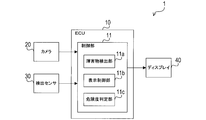
- FIG. 1 is a block diagram illustrating a configuration of an imaging system according to the first embodiment.
- FIG. 2 is an explanatory diagram of a shooting area and a shooting area in the first embodiment.
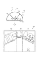
- FIG. 3 is an explanatory diagram of a first display image (normal image) in the first embodiment.
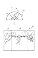
- FIG. 4 is an explanatory diagram of a second display image (warning image) in the first embodiment.
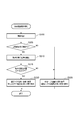
- FIG. 5 is a flowchart of the captured image display process in the first embodiment.
- FIG. 6 is an explanatory diagram of a shooting area and a shooting area in the second embodiment.
- FIG. 1 is a block diagram showing the configuration of the photographing system according to the present embodiment.
- An imaging system 1 according to the present embodiment is mounted on a vehicle and displays a captured image in front of the host vehicle on a display, and includes an ECU 10, a camera 20, a detection sensor 30, a display 40, and the like. .
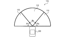
- FIG. 2 is an explanatory diagram of the shooting area and the shooting area in the present embodiment.
- the camera 20 captures an image capturing area 110 provided in front of the host vehicle 100 through a wide-angle lens, and outputs a video signal indicating the captured image to the ECU 10.
- the shooting area 110 includes three shooting areas (a plurality of shooting areas) including a first shooting area 111, a second shooting area 112, and a third shooting area 113.
- the detection sensor 30 is an object (for example, a moving object such as a pedestrian or a vehicle, an obstacle on the road, a guard rail provided along the road, a traffic light, a power pole, etc.) present in the imaging area 110 in front of the host vehicle 100. It is a sensor for detecting.
- the detection sensor 30 is configured by, for example, a radar or a sonar, and detects the position, size, type, and the like of an object existing in front of the host vehicle 100 by transmitting an exploration wave and detecting the reflected wave. To detect. Then, the detection sensor 30 outputs a detection signal indicating the detection result to the ECU 10.
- the detection sensor 30 may be constituted by a stereo camera, for example.
- the detection sensor 30 may be configured by the camera 20 and may detect an object in front of the host vehicle 100 by analyzing an image captured by the camera 20.
- the ECU 10 corresponds to the image generation apparatus according to the present embodiment, and includes a control unit 11 configured by a CPU, a ROM, a RAM, an I / O, and the like.
- the CPU of the control unit 11 executes a program stored in the ROM, thereby performing overall control of the ECU 10 and performing various processes. Further, the CPU of the control unit 11 functions as an obstacle detection unit 11a, a display control unit 11b, and a risk determination unit 11c by operating according to a program.
- the obstacle detection unit 11a detects the position, size, type, and the like of an object existing in front of the host vehicle 100 based on the detection signal from the detection sensor 30.
- the display control unit 11b generates captured image data based on the video signal from the camera 20.
- the display control unit 11b corrects the generated captured image data and generates display image data for displaying the entire captured area 110.
- the display control unit 11b outputs a video signal for displaying the generated display image data to the display 40.
- the display 40 is a display device configured by a liquid crystal display, an organic EL display, or the like, and displays an image based on a video signal from the ECU 10.
- the risk determination unit 11c determines a risk indicating the possibility that an object existing in front of the host vehicle 100 will contact (collision) with the host vehicle 100 based on the detection result of the detection sensor 30.
- the operation of the photographing system 1 will be described.
- the right side in the traveling direction of the host vehicle 100 (hereinafter referred to as “the front direction of the camera 20”) is simply described as “right”, and the left side in the traveling direction is simply “left”. It describes.
- the shooting area 110 extending in front of the host vehicle 100 has a fan shape with a central angle of 180 ° when viewed in plan. That is, the shooting area 110 extends horizontally around the front of the host vehicle 100.
- the shooting area 110 is composed of three shooting areas in which the first shooting area 111, the second shooting area 112, and the third shooting area 113 are each formed in a fan shape. That is, the first shooting area 111, the second shooting area 112, and the third shooting area 113 are arranged in a line in a horizontal direction that intersects the front direction of the camera 20.
- the central angle is not limited to 180 °.
- the ECU 10 displays the photographed image of the photographing region 110 on the display 40 based on the photographed image data acquired from the camera 20.
- the display image displayed on the display 40 is divided into three image regions (right image region, center image region, and left image region) arranged in the left-right direction.
- the captured image of the first imaging area (right edge area) 111 is displayed.
- the central image area a captured image of the second imaging area (central area) 112 is displayed.
- a captured image of the third imaging area (left edge area) 113 is displayed.
- the camera 20 images the imaging region 110 through a wide-angle lens. Therefore, the captured image generated as it is from the video signal of the camera 20 is in a state where the right and left portions of the image are distorted. Therefore, the ECU (image generation device) 10 according to the present embodiment corrects the captured image data to generate display image data, and displays the captured image of the imaging region 110 on the display 40 based on the generated display image data. To do. At this time, the ECU 10 corrects the content according to the detection result of the object by the detection sensor 30.
- FIG. 3 shows an explanatory diagram of the first display image (normal image) in the present embodiment.
- FIG. 3 shows an example of a pedestrian as an example of the object 120 detected by the detection sensor 30.
- the first shooting area 111 is referred to as a “right edge area 111” and the second shooting area 112 is referred to as a “center area 112” in order to easily understand the positional relationship of the shooting areas.
- the third imaging area 113 is referred to as “left edge area 113”. It is difficult for a driver who is driving to visually recognize the right edge area 111 and the left edge area 113 directly as compared to the central area 112.
- the ECU 10 displays the first display image (hereinafter referred to as “normal image”) in which the right edge area 111 and the left edge area 113 have higher visibility than the central area 112. 150 ”is displayed on the display 40. That is, when the object 120 does not exist in the central area 112, the ECU 10 displays the captured images of the right edge area 111 and the left edge area 113 in a display format that is easy for the driver to visually recognize (a state where the visual recognition is easy). To display.
- the captured image of the central area 112 is reduced (hereinafter referred to as "reduced state") from the captured images of the right edge area 111 and the left edge area 113. It is displayed.
- reduced state a predetermined reduction ratio in a horizontal direction D (right and left direction with respect to the front direction of the camera 20) perpendicular to the straight line P (center line) that bisects the central angle ⁇ b of the center area 112.
- the captured images of the right edge area 111 and the left edge area 113 are not reduced (unreduced state), or It is displayed in a reduced state at a reduction rate lower than the reduction rate applied to the central area 112.
- the image is not reduced (corrected) so that the driver's visibility is higher than the display image of the central area 112 displayed in the reduced state (so that the driver can easily see).
- a display example of a state (a state close to an image when directly viewed by a driver) is shown.
- a display example in a state where the image is reduced and corrected at a reduction rate lower than the reduction state of the central area 112 is shown. That is, in the example illustrated in FIG. 3, the captured images of the right edge area 111 and the left edge area 113 are displayed in an enlarged state with respect to the captured image of the central area 112 where the object 120 does not exist (relative). Is magnified).
- the degree of reduction of the image in each shooting area is set so that the image of the shooting area where the object 120 exists is displayed more easily than the images of other shooting areas. Adjust and correct the captured image data.
- display image data that displays the entire imaging region 110 is generated.
- a display state with high driver visibility is referred to as a “normal state” for convenience.
- the ECU 10 has a second display image (hereinafter referred to as “hereinafter,“ higher visibility) in the central area 112 than in the right edge area 111 and the left edge area 113 ”. Is displayed on the display 40.
- FIG. 4 shows a display example when the object 120 is present in the central area 112.
- a captured image of the central area 112 where the object 120 exists is displayed in a normal state.
- the captured images of the right edge area 111 and the left edge area 113 are displayed in a reduced state.
- FIG. 10 the captured image display process in which the ECU (image generation device) 10 according to the present embodiment generates a captured image of the imaging region 110 based on the video signal from the camera 20 and displays the captured image on the display 40 is illustrated in FIG. This will be described with reference to a flowchart. In addition, this process is periodically performed by CPU of the control part 11 which ECU10 has.
- the CPU of the control unit 11 detects the position, size, type, and the like of the object 120 existing in front of the host vehicle 100 based on the detection signal from the detection sensor 30 (S200), and proceeds to the process of S205. As described above, the CPU of the control unit 11 functions as the obstacle detection unit 11a by executing the process of S200. Next, the CPU determines whether or not the object 120 exists in front of the host vehicle 100 (S205). As a result, if the CPU determines that the object 120 is present in front of the host vehicle 100 (S205: YES), the CPU proceeds to the process of S210. On the other hand, when determining that the object 120 does not exist in front of the host vehicle 100 (S205: NO), the CPU proceeds to the process of S225.
- the CPU calculates the position of the center of gravity of the detected object 120 (S210), and proceeds to the process of S215.
- the CPU may calculate the position of the center of gravity of the object 120 by the following method, for example. Specifically, an area where the detected object 120 exists (hereinafter referred to as “object area”) is specified on the horizontal plane where the host vehicle 100 exists, and the center of the specified area is regarded as the barycentric position.
- the CPU determines whether or not the calculated center of gravity position is located in the central area 112 of the imaging region 110 (S215). As a result, when the CPU determines that the position of the center of gravity is located in the central area 112 (S215: YES), the CPU proceeds to the process of S220 and displays the warning image 160 on the display 40. At this time, the CPU determines the central area 112 of the imaging region 110 where the object 120 exists as a target area to be displayed in a state where the visual recognition is easy. As a result, the CPU displays the captured images of the right edge area 111 and the left edge area 113 of the shooting area 110 in a reduced state, and displays the captured image of the central area 112 where the object 120 exists in a normal state.
- the captured image data is corrected, and display image data for displaying the entire captured area 110 is generated (S220).
- the captured image of the central area 112 is enlarged and displayed as compared with the captured images of the right edge area 111 and the left edge area 113. That is, the CPU relatively enlarges and displays the captured image of the central area 112 where the object 120 exists, and displays the detected object 120 in a display format that allows easy visual recognition (a state in which visual recognition is easy).
- the CPU determines that the position of the center of gravity is not located in the central area 112 (S215: NO)
- the CPU proceeds to the process of S225 and displays the normal image 150 on the display 40.
- the CPU determines the right edge area 111 and the left edge area 113 of the imaging region 110 that are difficult to view directly as target areas to be displayed in a state where the viewing is easy.
- the CPU captures the captured image so that the captured image of the central area 112 of the capturing area 110 is displayed in a reduced state and the captured images of the right edge area 111 and the left edge area 113 are displayed in a normal state.
- Data is corrected, and display image data for displaying the entire photographing area 110 is generated (S225). Thereby, each captured image of the right edge area 111 and the left edge area 113 is displayed in an enlarged manner as compared with the captured image of the central area 112.
- the CPU displays the right edge area 111 and the left edge area 113 that are difficult for the driving driver to visually recognize more easily than the central area 112 in a display format (in an easily visible state). To do.
- the CPU of the control unit 11 functions as the display control unit 11b by executing the processes of S220 and S225.
- the determination condition is that the condition for determining that the object 120 has newly entered the central area 112 of the imaging region 110 when the object 120 does not exist in the central area 112 of the imaging region 110 is the entry condition.
- the determination condition is that the condition for determining that the object 120 existing in the central area 112 has moved out of the area is the retreat condition.
- one of the entry condition and the leaving condition may be a condition that makes it difficult for the condition to be satisfied as compared with the other condition.
- the entry condition is that at least a part of the object region of the object 120 existing outside the central area 112 is located in the central area 112, It is also good.
- the retreat condition is that all the object areas of the object 120 that existed in the area of the central area 112 are located outside the area of the central area 112, or that the center of gravity of the object 120 is The fact that the object 120 is located outside the area 112 may be set as the retreat condition of the object 120.
- the entry condition is that all the object regions of the object 120 that existed outside the central area 112 are located within the area of the central area 112, and that the center of gravity of the object 120 is
- the entry condition for the object 120 may be determined to be within the central area 112.
- the retreat condition is that the retreat condition of the object 120 is that at least a part of the object region of the object 120 existing in the area of the central area 112 is located outside the area of the central area 112. Also good.
- the processes of S220 and S225 are executed as follows.
- the CPU of the control unit 11 determines that the object 120 does not exist in the central area 112, and executes the process of S220 when the entry condition is satisfied. On the other hand, if the entry condition is not satisfied, the process of S225 is executed. Further, the CPU of the control unit 11 determines that the object 120 exists in the central area 112, and executes the process of S220 when the retreat condition is not satisfied. On the other hand, if the retreat condition is satisfied, the process of S225 is executed.
- the ECU (image generating device) 10 displays the normal image 150 and the warning image 160 displayed on the display 40 when the object 120 is present near the boundary of the central area 112 (display image). ) Can prevent frequent switching.
- the CPU of the control unit 11 In the display process of S220, the CPU of the control unit 11 generates captured image data based on the video signal from the camera 20, corrects the generated captured image data, and displays a warning image 160 (the central area 112 in the normal state, Display image data of an image in which the edge area 111 and the left edge area 113 are displayed in a reduced state is generated. As a result, the CPU of the control unit 11 outputs a video signal for displaying the display image data to the display 40, displays the warning image 160 on the display 40, and ends this process.
- the CPU of the control unit 11 executes the following display process. You may do it.
- the CPU generates the display image data of the warning image 160 that displays the center area 112 and the edge area where the object 120 exists in a normal state and displays the edge area where the object 120 does not exist in a reduced state.
- the CPU of the control unit 11 in the display processing of S225, the CPU of the control unit 11 generates captured image data based on the video signal from the camera 20, corrects the generated captured image data, and normal image 150 (the central area 112 in a reduced state). Display image data of the right edge area 111 and the left edge area 113 displayed in a normal state). As a result, the CPU of the control unit 11 outputs a video signal for displaying the display image data to the display 40, displays the normal image 150 on the display 40, and ends this process.
- a captured image overlooking the periphery of the host vehicle 100 is displayed on the display 40.
- the warning image 160 that displays the central area 112 in a normal state and displays the right edge area 111 and the left edge area 113 in a reduced state. Is displayed.
- the central area 112 is displayed in a reduced state, and the right edge area 111 and the left edge are displayed.
- a normal image 150 that displays the partial area 113 in a normal state is displayed.
- the photographing area where the object 120 exists can be displayed on the displayed photographed image in a state where it is easy to visually recognize (a state with high visibility). Thereby, the driver can easily recognize the object 120 (an object existing around the host vehicle 100) existing in the imaging region 110.
- the right edge area 111, the center area 112, and the left edge area 113 are each formed in a fan shape, and the horizontal direction D (with respect to the front direction of the camera 20) It is lined up in a line in the horizontal direction.
- photography system 1 which has the image generation apparatus which concerns on this embodiment, the picked-up image of the imaging
- the photographed image in the photographing area where the object 120 does not exist is displayed in a reduced state corrected and corrected in the horizontal direction D (left-right direction) with respect to the front direction of the camera 20.
- a captured image overlooking the periphery of the host vehicle 100 is displayed, and when the object 120 exists in the imaging area, the object 120 is displayed on the displayed captured image.
- the captured images of the right edge area 111 and the left edge area 113 are enlarged and displayed. Thereby, the driver during driving can easily visually recognize the right edge area 111 and the left edge area 113 that are difficult to directly visually recognize.
- the imaging system 1 according to the present embodiment is configured in the same manner as in the first embodiment, but differs in the following points.
- the ECU (image generation device) 10 according to the present embodiment determines a risk level indicating the possibility that the object 120 may contact the host vehicle 100 based on a predetermined reference. Then, the ECU 10 according to the present embodiment determines a target area that is a shooting area to be displayed in an easily viewable state from a plurality of shooting areas based on the determined risk (determination result). In response to the result, the ECU 10 according to the present embodiment determines one of the normal image 150 and the warning image 160 as a display image to be displayed on the display 40. As described above, the present embodiment is different from the first embodiment in that the CPU of the control unit 11 of the ECU 10 functions as the risk determination unit 11c by executing a predetermined process.
- FIG. 6 is an explanatory diagram of the shooting area 110 and the shooting areas 111, 112, and 113 in the present embodiment.
- the relative position from the host vehicle 100 is indicated by the position on the coordinate space that extends concentrically from the center O of the imaging region 110.
- each imaging area 111, 112, 113 according to the present embodiment is divided into three zones (A zone, B zone, C zone) according to the relative distance from the host vehicle 100.
- each area is associated (set) with a risk level assigned to the area according to a predetermined criterion. Therefore, the object 120 existing in each of the imaging areas 111, 112, and 113 is determined as to the degree of danger with respect to the host vehicle 100 based on the area where the object 120 is located.
- the degree of risk indicating the possibility that the object 120 contacts the host vehicle 100 during traveling is set in four stages. For example, in the right edge area 111 and the left edge area 113, the degree of risk [3] is set in the A sections 111a and 113a at positions closest to the host vehicle 100. Further, the risk level [2] is set for the B zones 111b and 113b next to the host vehicle 100, and the risk level [1] is set for the C zones 111c and 113c farthest from the host vehicle 100. .
- the degree of risk [4] is set for the A section 112a closest to the host vehicle 100. Further, the risk level [3] is set for the B zone 112 b next to the host vehicle 100, and the risk level [2] is set for the C zone 112 c farthest from the host vehicle 100.
- a value indicating a high degree of risk is set for a position close to the host vehicle 100, while a value indicating a low degree of risk is set for a position far from the host vehicle 100.
- the degree of danger set in the area where the object 120 exists is determined as the degree of danger of the object 120 with respect to the host vehicle 100.
- the degree of risk is determined based on criteria such as the moving direction and moving speed of the object 120 identified from the detection signal from the detection sensor 30, the type of the object 120 (whether it is a pedestrian, a vehicle, or a guardrail). You may judge. Specifically, in the determination method based on the moving direction, the object 120 moving toward the host vehicle 100 has a higher risk than the object 120 moving away from the host vehicle 100. It may be determined that In the determination method based on the moving speed, the object 120 moving at a speed equal to or higher than a predetermined value may be determined to have a higher degree of risk than the object 120 that is not.
- the object 120 such as a pedestrian, a bicycle, or a motorcycle has a higher degree of risk than the object 120 of a four-wheeled vehicle such as a normal car or a large car. You may judge.
- the risk level of each object 120 may be determined based on each criterion, and the sum of the determined risk levels of each criterion may be determined as the final risk level of the object 120.
- the CPU of the control unit 11 included in the ECU 10 is detected in addition to the process shown in the first embodiment (the process of calculating the center of gravity position of the object 120). The degree of danger of the object 120 to the host vehicle 100 is determined.
- the CPU determines a target area to be displayed in an easily viewable state from the plurality of shooting areas based on the shooting area where the object 120 exists and the risk level of the object 120, and based on the result. Then, the type of display image (normal image 150 or warning image 160) is determined.
- the CPU selects the type of display image as in the first embodiment. decide.
- the process proceeds to S220 and the warning image 160 is displayed.
- the process may proceed to S225 and the normal image 150 may be displayed.
- the process of S220 (warning) The process proceeds to (display processing of image 160). On the other hand, if the value is small, the process may proceed to S225 (display process of the normal image 150).
- the following effects are obtained in addition to the effects according to the first embodiment. That is, when there are a plurality of objects 120 in the shooting area 110, in addition to the determination result as to which shooting area the detected object 120 exists in the shooting area 110, the subject vehicle 100 of the object 120. The type of display image is switched based on the determination result of the degree of risk for Thereby, in the imaging system 1 having the image generation apparatus according to the present embodiment, it is possible to enlarge and display the imaging area where the object 120 having a high possibility (risk level) of contact with the host vehicle 100 exists. Can call attention.
- the imaging region 110 is provided in front of the host vehicle 100, but the present invention is not limited to this. In other embodiments, for example, the imaging region 110 may be provided at the rear or side of the host vehicle 100.
- the shape of the imaging region 110 is a fan shape, but is not limited thereto.
- the imaging region 110 may have a region shape that extends in the horizontal direction D with respect to the front direction of the camera 20.
- the shooting area 110 may be composed of two or four or more shooting areas arranged in a line in a direction D horizontal to the front direction of the camera 20.
- an imaging area that is easy to visually recognize (highly visible) for the driving driver is handled in the same manner as the central area 112 in the first and second embodiments.
- it is conceivable to perform a captured image display process by handling a photographing area that is difficult to view directly (low visibility) in the same manner as the right edge area 111 and the left edge area 113.
- the shooting area located immediately behind the host vehicle 100 is set as the central area 112. Furthermore, it is conceivable to perform the captured image display processing with the imaging areas located on the left and right sides of the central area 112 as the right edge area 111 and the left edge area 113. At this time, the central image area 162 in the warning image 160 may be enlarged and the central area 112 may be displayed larger than in the case where the front of the host vehicle 100 is the shooting area 110. In other embodiments, by adopting such a configuration, the same effects as those of the first and second embodiments can be obtained.
- the functions of one component in the first and second embodiments are distributed as a plurality of components, or the functions of a plurality of components are integrated into one component. Or you may.
- at least a part of the configuration according to the first and second embodiments may be replaced with a known configuration having the same function.
- a part of the configuration according to the first and second embodiments may be omitted.
- at least a part of the configuration according to the first or second embodiment may be added to or replaced with the configuration according to the other embodiment.
- the imaging system 1 includes, in addition to the configurations described in the above embodiments, components of the imaging system 1, a program for causing a computer to function as the imaging system 1, a medium on which the program is recorded, and a captured image display It can also be realized in various forms such as a method for realizing processing.
- the ECU 10 included in the imaging system 1 according to the above embodiment corresponds to an image generation device.
- S200 to S215 of the photographed image display process functions as the obstacle detection unit 11a of the control unit 11 and corresponds to a determination unit.
- S220 and S225 of the captured image display process function as the display control unit 11b of the control unit 11, and correspond to an acquisition unit, a determination unit, a generation unit, and a display unit.
- the central area 112 of the shooting area 110 corresponds to an easy-to-view area
- the right edge area 111 and the left edge area 113 of the shooting area 110 correspond to difficult-to-view areas.
- SYMBOLS 1 ... Shooting system, 10 ... ECU, 11 ... Control part, 11a ... Obstacle detection part, 11b ... Display control part, 20 ... Camera, 30 ... Detection sensor, 40 ... Display, 100 ... Own vehicle, 110 ... Shooting area
Landscapes
- Engineering & Computer Science (AREA)
- Physics & Mathematics (AREA)
- General Physics & Mathematics (AREA)
- Remote Sensing (AREA)
- Radar, Positioning & Navigation (AREA)
- Multimedia (AREA)
- Theoretical Computer Science (AREA)
- Computer Networks & Wireless Communication (AREA)
- Signal Processing (AREA)
- Mechanical Engineering (AREA)
- Computer Vision & Pattern Recognition (AREA)
- Acoustics & Sound (AREA)
- Electromagnetism (AREA)
- Human Computer Interaction (AREA)
- Closed-Circuit Television Systems (AREA)
- Traffic Control Systems (AREA)
- Image Analysis (AREA)
- Image Processing (AREA)
Abstract
An ECU (10) is equipped with: an acquisition means (S220, S225) that photographs an imaging region (110) at the periphery of a host vehicle (100) and formed from multiple imaging areas (111-113), and thereby acquires photographic image data; a determination means (S200-S215) that, on the basis of the detection result for an object (120) present at the periphery of the host vehicle, determines whether an object is present in the imaging areas; a selection means (S220, S225) that, on the basis of the determination result, selects from among the multiple imaging areas a subject area to be displayed in an easily visible manner; and a generation means (S220, S225) that performs a reduction correction on the photographic image data for each imaging area so as to display the image of the subject area in a more easily visible manner in comparison with the other imaging areas, thereby generating display image data displaying the entire imaging region.
Description
本開示は、画像生成技術に関する。
This disclosure relates to image generation technology.
従来の方法では、一台の広角カメラにより撮影された自車両周辺の歪曲画像に所定の補正を加え、広角カメラの正面,左方,右方を写した歪曲していない3つの画像を生成し、これらを1つの画面上に並べて表示することが知られている(特許文献1)。
In the conventional method, a predetermined correction is applied to a distorted image around the host vehicle taken by one wide-angle camera, and three undistorted images are captured that show the front, left, and right sides of the wide-angle camera. It is known that these are displayed side by side on one screen (Patent Document 1).
しかしながら、通常、運転中のドライバは自車両の正面を視認している。そのため、単に自車両周辺の撮影画像を歪曲していない状態で表示するだけでは、自車両周辺に存在する物体を認識できない可能性がある。
However, the driver who is driving usually visually recognizes the front of the host vehicle. For this reason, there is a possibility that an object existing around the host vehicle cannot be recognized by simply displaying the captured image around the host vehicle without distortion.
本開示は、ドライバが自車両周辺に存在する物体を容易に認識できるようにすることを目的とする。
This disclosure is intended to enable a driver to easily recognize an object existing around the host vehicle.
本開示の画像生成装置は、複数の撮影エリアから構成される自車両周辺の撮影領域を、カメラにより広角レンズを通して撮影し、撮影画像データを取得する取得手段と、自車両周辺に存在する物体を検出し、検出結果に基づき、撮影エリアに物体が存在するか否かを判定する判定手段と、判定手段による判定結果に基づき、複数の撮影エリアの中から、視認が容易な状態で表示させる対象エリアを決定する決定手段と、対象エリアの画像が他の撮影エリアの画像に比べて、視認が容易な状態で表示されるように、各撮影エリアの画像の縮小度合いを調整し、撮影画像データを補正することで、撮影領域全体を表示する表示画像データを生成する生成手段と、表示画像データを表示させる表示手段と、を備える。
An image generation apparatus according to the present disclosure includes an acquisition unit that captures a photographing region around a host vehicle including a plurality of photographing areas through a wide-angle lens using a camera, and acquires an object existing around the host vehicle. A detection unit that detects and determines whether or not an object exists in the shooting area based on the detection result, and an object to be displayed in an easily viewable state from a plurality of shooting areas based on the determination result by the determination unit The deciding means for deciding the area, and adjusting the degree of reduction of the image in each shooting area so that the image in the target area is displayed more easily than the image in the other shooting area. Is provided, generating means for generating display image data for displaying the entire imaging region, and display means for displaying the display image data.
本開示の画像生成装置は、このような構成によって、自車両周辺を見渡す撮影画像を表示し、表示した撮影画像上において、物体が存在する撮影エリアを視認が容易な状態(視認性の高い状態)で表示できる。このため、ドライバは、自車両周辺に存在する物体を容易に認識できる。
With such a configuration, the image generation apparatus according to the present disclosure displays a captured image overlooking the periphery of the host vehicle, and in the displayed captured image, a state in which a captured area where an object exists is easily visible (a state with high visibility) ). For this reason, the driver can easily recognize objects existing around the host vehicle.
なお、本項目に記載した内容は、後述する実施形態に記載の具体的手段との対応関係を示すものであって、本開示の技術的範囲を限定するものではない。
Note that the content described in this item indicates a correspondence relationship with specific means described in the embodiments described later, and does not limit the technical scope of the present disclosure.
以下、本開示の実施形態について図面を用いて説明する。
[第1実施形態]
[構成の説明]
図1には、本実施形態に係る撮影システムの構成を示すブロック図が示されている。本実施形態に係る撮影システム1は、車両に搭載され、自車両前方の撮影画像をディスプレイに表示するものであり、ECU10と、カメラ20と、検出センサ30と、ディスプレイ40等を有している。 Hereinafter, embodiments of the present disclosure will be described with reference to the drawings.
[First Embodiment]
[Description of configuration]
FIG. 1 is a block diagram showing the configuration of the photographing system according to the present embodiment. Animaging system 1 according to the present embodiment is mounted on a vehicle and displays a captured image in front of the host vehicle on a display, and includes an ECU 10, a camera 20, a detection sensor 30, a display 40, and the like. .
[第1実施形態]
[構成の説明]
図1には、本実施形態に係る撮影システムの構成を示すブロック図が示されている。本実施形態に係る撮影システム1は、車両に搭載され、自車両前方の撮影画像をディスプレイに表示するものであり、ECU10と、カメラ20と、検出センサ30と、ディスプレイ40等を有している。 Hereinafter, embodiments of the present disclosure will be described with reference to the drawings.
[First Embodiment]
[Description of configuration]
FIG. 1 is a block diagram showing the configuration of the photographing system according to the present embodiment. An
図2には、本実施形態における撮影領域及び撮影エリアの説明図が示されている。カメラ20は、自車両100の前方に設けられた撮影領域110を、広角レンズを通して撮影し、撮影画像を示す映像信号をECU10に出力する。なお、本実施形態に係る撮影領域110は、第1撮影エリア111、第2撮影エリア112、及び第3撮影エリア113の3つの撮影エリア(複数の撮影エリア)で構成されている。
FIG. 2 is an explanatory diagram of the shooting area and the shooting area in the present embodiment. The camera 20 captures an image capturing area 110 provided in front of the host vehicle 100 through a wide-angle lens, and outputs a video signal indicating the captured image to the ECU 10. Note that the shooting area 110 according to the present embodiment includes three shooting areas (a plurality of shooting areas) including a first shooting area 111, a second shooting area 112, and a third shooting area 113.
図1の説明に戻る。検出センサ30は、自車両100の前方の撮影領域110に存在する物体(例えば、歩行者や車両等の移動体、道路上の障害物、道路に沿って設けられたガードレール、信号機や電柱等)を検出するためのセンサである。検出センサ30は、例えばレーダやソナー等で構成されており、探査波を送信してその反射波を検出することで、自車両100の前方に存在する物体の位置、大きさ、及び種別等を検出する。そして、検出センサ30は、検出結果を示す検出信号をECU10に出力する。
Return to the explanation of Fig. 1. The detection sensor 30 is an object (for example, a moving object such as a pedestrian or a vehicle, an obstacle on the road, a guard rail provided along the road, a traffic light, a power pole, etc.) present in the imaging area 110 in front of the host vehicle 100. It is a sensor for detecting. The detection sensor 30 is configured by, for example, a radar or a sonar, and detects the position, size, type, and the like of an object existing in front of the host vehicle 100 by transmitting an exploration wave and detecting the reflected wave. To detect. Then, the detection sensor 30 outputs a detection signal indicating the detection result to the ECU 10.
この他にも、検出センサ30は、例えばステレオカメラ等で構成されていても良い。また、検出センサ30は、カメラ20で構成し、カメラ20による撮影画像を解析することで、自車両100の前方の物体を検出しても良い。
In addition to this, the detection sensor 30 may be constituted by a stereo camera, for example. In addition, the detection sensor 30 may be configured by the camera 20 and may detect an object in front of the host vehicle 100 by analyzing an image captured by the camera 20.
ECU10は、本実施形態に係る画像生成装置に相当し、CPU,ROM,RAM,I/O等から構成された制御部11を有している。制御部11のCPUは、ROMに格納されたプログラムを実行することで、ECU10を統括制御し、各種処理を実施する。また、制御部11のCPUは、プログラムに従い動作することで、障害物検出部11aと、表示制御部11bと、危険度判定部11cとして機能する。
The ECU 10 corresponds to the image generation apparatus according to the present embodiment, and includes a control unit 11 configured by a CPU, a ROM, a RAM, an I / O, and the like. The CPU of the control unit 11 executes a program stored in the ROM, thereby performing overall control of the ECU 10 and performing various processes. Further, the CPU of the control unit 11 functions as an obstacle detection unit 11a, a display control unit 11b, and a risk determination unit 11c by operating according to a program.
障害物検出部11aは、検出センサ30からの検出信号に基づき、自車両100の前方に存在する物体の位置、大きさ、及び種別等を検出する。
The obstacle detection unit 11a detects the position, size, type, and the like of an object existing in front of the host vehicle 100 based on the detection signal from the detection sensor 30.
表示制御部11bは、カメラ20からの映像信号に基づき、撮影画像データを生成する。表示制御部11bは、生成した撮影画像データを補正し、撮影領域110全体を表示する表示画像データを生成する。表示制御部11bは、生成した表示画像データを表示するための映像信号をディスプレイ40に出力する。なお、ディスプレイ40は、液晶ディスプレイや有機ELディスプレイ等で構成された表示装置であり、ECU10からの映像信号に基づき、画像を表示する。
The display control unit 11b generates captured image data based on the video signal from the camera 20. The display control unit 11b corrects the generated captured image data and generates display image data for displaying the entire captured area 110. The display control unit 11b outputs a video signal for displaying the generated display image data to the display 40. The display 40 is a display device configured by a liquid crystal display, an organic EL display, or the like, and displays an image based on a video signal from the ECU 10.
また、危険度判定部11cは、検出センサ30による検出結果に基づき、自車両100の前方に存在する物体が、自車両100に接触(衝突)する可能性を示す危険度を判定する。
Also, the risk determination unit 11c determines a risk indicating the possibility that an object existing in front of the host vehicle 100 will contact (collision) with the host vehicle 100 based on the detection result of the detection sensor 30.
[動作の説明]
次に、撮影システム1の動作について説明する。なお、以後の説明では、自車両100の進行方向(以下「カメラ20の正面方向」という)に向かって右側を、単に「右」と記載し、進行方向に向かって左側を、単に「左」と記載する。 [Description of operation]
Next, the operation of thephotographing system 1 will be described. In the following description, the right side in the traveling direction of the host vehicle 100 (hereinafter referred to as “the front direction of the camera 20”) is simply described as “right”, and the left side in the traveling direction is simply “left”. It describes.
次に、撮影システム1の動作について説明する。なお、以後の説明では、自車両100の進行方向(以下「カメラ20の正面方向」という)に向かって右側を、単に「右」と記載し、進行方向に向かって左側を、単に「左」と記載する。 [Description of operation]
Next, the operation of the
図2に示すように、自車両100の前方に広がる撮影領域110は、平面視すると中心角が180°の扇状となっている。つまり、撮影領域110は、自車両100の前方周辺に水平に広がっている。また、撮影領域110は、第1撮影エリア111、第2撮影エリア112、及び第3撮影エリア113それぞれが扇状に形成された3つの撮影エリアで構成されている。つまり、第1撮影エリア111、第2撮影エリア112、及び第3撮影エリア113は、カメラ20の正面方向に交差する水平の方向に一列に並んでいる。なお、中心角の角度は180°に限定されることは無い。また、撮影領域110の右端に位置する第1撮影エリア111(右縁部エリア)の中心角θaと、撮影領域110の左端に位置する第3撮影エリア113(左縁部エリア)の中心角θcは、同じ角度(θa=θc)になっている。
As shown in FIG. 2, the shooting area 110 extending in front of the host vehicle 100 has a fan shape with a central angle of 180 ° when viewed in plan. That is, the shooting area 110 extends horizontally around the front of the host vehicle 100. The shooting area 110 is composed of three shooting areas in which the first shooting area 111, the second shooting area 112, and the third shooting area 113 are each formed in a fan shape. That is, the first shooting area 111, the second shooting area 112, and the third shooting area 113 are arranged in a line in a horizontal direction that intersects the front direction of the camera 20. The central angle is not limited to 180 °. Further, the central angle θa of the first imaging area 111 (right edge area) located at the right end of the imaging area 110 and the central angle θc of the third imaging area 113 (left edge area) located at the left end of the imaging area 110. Are at the same angle (θa = θc).
ECU10は、カメラ20から取得した撮影画像データに基づき、撮影領域110の撮影画像をディスプレイ40に表示する。なお、ディスプレイ40に表示される表示画像は、左右の方向に並ぶ3つの画像領域(右の画像領域、中央の画像領域、左の画像領域)に分割される。そして、右の画像領域には、第1撮影エリア(右縁部エリア)111の撮影画像が表示される。中央の画像領域には、第2撮影エリア(中央エリア)112の撮影画像が表示される。左の画像領域には、第3撮影エリア(左縁部エリア)113の撮影画像が表示される。
The ECU 10 displays the photographed image of the photographing region 110 on the display 40 based on the photographed image data acquired from the camera 20. The display image displayed on the display 40 is divided into three image regions (right image region, center image region, and left image region) arranged in the left-right direction. In the right image area, the captured image of the first imaging area (right edge area) 111 is displayed. In the central image area, a captured image of the second imaging area (central area) 112 is displayed. In the left image area, a captured image of the third imaging area (left edge area) 113 is displayed.
ここで、カメラ20は、広角レンズを通して撮影領域110を撮影している。そのため、カメラ20の映像信号からそのまま生成された撮影画像は、画像の右側及び左側の部分が歪んだ状態になる。そこで、本実施形態に係るECU(画像生成装置)10は、撮影画像データを補正して表示画像データを生成し、生成した表示画像データに基づいて、撮影領域110の撮影画像をディスプレイ40に表示する。この時、ECU10は、検出センサ30による物体の検出結果に応じた内容の補正を行う。
Here, the camera 20 images the imaging region 110 through a wide-angle lens. Therefore, the captured image generated as it is from the video signal of the camera 20 is in a state where the right and left portions of the image are distorted. Therefore, the ECU (image generation device) 10 according to the present embodiment corrects the captured image data to generate display image data, and displays the captured image of the imaging region 110 on the display 40 based on the generated display image data. To do. At this time, the ECU 10 corrects the content according to the detection result of the object by the detection sensor 30.
図3には、本実施形態における第1表示画像(通常画像)の説明図が示されている。また、図3には、検出センサ30によって検出される物体120の一例として歩行者の例が示されている。なお、以降の説明では、撮影エリアの位置関係を分かりやすく説明するために、第1撮影エリア111を「右縁部エリア111」と称し、第2撮影エリア112を「中央エリア112」と称し、第3撮影エリア113を「左縁部エリア113」と称す。運転中のドライバは、中央エリア112に比べて、右縁部エリア111及び左縁部エリア113を直接視認するのが困難である。そこで、ECU10は、中央エリア112に物体120が存在しない場合、中央エリア112に比べて、右縁部エリア111及び左縁部エリア113の方が視認性の高い第1表示画像(以下「通常画像」という)150をディスプレイ40に表示する。つまり、ECU10は、中央エリア112に物体120が存在しない場合、右縁部エリア111及び左縁部エリア113の各撮影画像を、ドライバが視認しやすい表示形式(視認が容易な状態)でディスプレイ40に表示させる。
FIG. 3 shows an explanatory diagram of the first display image (normal image) in the present embodiment. FIG. 3 shows an example of a pedestrian as an example of the object 120 detected by the detection sensor 30. In the following description, the first shooting area 111 is referred to as a “right edge area 111” and the second shooting area 112 is referred to as a “center area 112” in order to easily understand the positional relationship of the shooting areas. The third imaging area 113 is referred to as “left edge area 113”. It is difficult for a driver who is driving to visually recognize the right edge area 111 and the left edge area 113 directly as compared to the central area 112. Therefore, when the object 120 does not exist in the central area 112, the ECU 10 displays the first display image (hereinafter referred to as “normal image”) in which the right edge area 111 and the left edge area 113 have higher visibility than the central area 112. 150 ”is displayed on the display 40. That is, when the object 120 does not exist in the central area 112, the ECU 10 displays the captured images of the right edge area 111 and the left edge area 113 in a display format that is easy for the driver to visually recognize (a state where the visual recognition is easy). To display.
通常画像150における中央の画像領域152には、中央エリア112の撮影画像が、右縁部エリア111及び左縁部エリア113の各撮影画像より、縮小された状態(以下「縮小状態」という)で表示されている。図3に示す例では、中央エリア112の中心角θbを2等分する直線P(中央線)と直交する水平の方向D(カメラ20の正面方向に対して左右方向)に、所定の縮小率で画像を縮小し補正された状態の表示例が示されている。
In the central image area 152 in the normal image 150, the captured image of the central area 112 is reduced (hereinafter referred to as "reduced state") from the captured images of the right edge area 111 and the left edge area 113. It is displayed. In the example shown in FIG. 3, a predetermined reduction ratio in a horizontal direction D (right and left direction with respect to the front direction of the camera 20) perpendicular to the straight line P (center line) that bisects the central angle θb of the center area 112. A display example in which the image is reduced and corrected is shown.
一方、通常画像150における右の画像領域151及び左の画像領域153には、右縁部エリア111及び左縁部エリア113の各撮影画像が、縮小されていない状態(非縮小状態)、又は、中央エリア112に適用した縮小率よりも低い縮小率で縮小された状態で表示されている。図3に示す例では、縮小状態で表示された中央エリア112の表示画像よりも、ドライバの視認性が高くなるように(視認が容易となるように)、画像が縮小(補正)されていない状態(ドライバが直接目視した場合の映像に近い状態)の表示例が示されている。又は、中央エリア112の縮小状態よりも低い縮小率で画像を縮小し補正された状態の表示例が示されている。つまり、図3に示す例では、物体120が存在しない中央エリア112の撮影画像に対して、右縁部エリア111及び左縁部エリア113の各撮影画像が拡大状態で表示されている(相対的に拡大表示されている)。このように、本実施形態では、物体120が存在する撮影エリアの画像が他の撮影エリアの画像に比べて、視認が容易な状態で表示されるように、各撮影エリアの画像の縮小度合いを調整し、撮影画像データを補正する。その結果、本実施形態では、撮影領域110全体を表示する表示画像データを生成する。なお、以降の説明では、便宜上、ドライバの視認性が高い表示状態を「通常状態」を称す。
On the other hand, in the right image area 151 and the left image area 153 in the normal image 150, the captured images of the right edge area 111 and the left edge area 113 are not reduced (unreduced state), or It is displayed in a reduced state at a reduction rate lower than the reduction rate applied to the central area 112. In the example shown in FIG. 3, the image is not reduced (corrected) so that the driver's visibility is higher than the display image of the central area 112 displayed in the reduced state (so that the driver can easily see). A display example of a state (a state close to an image when directly viewed by a driver) is shown. Alternatively, a display example in a state where the image is reduced and corrected at a reduction rate lower than the reduction state of the central area 112 is shown. That is, in the example illustrated in FIG. 3, the captured images of the right edge area 111 and the left edge area 113 are displayed in an enlarged state with respect to the captured image of the central area 112 where the object 120 does not exist (relative). Is magnified). As described above, in the present embodiment, the degree of reduction of the image in each shooting area is set so that the image of the shooting area where the object 120 exists is displayed more easily than the images of other shooting areas. Adjust and correct the captured image data. As a result, in the present embodiment, display image data that displays the entire imaging region 110 is generated. In the following description, a display state with high driver visibility is referred to as a “normal state” for convenience.
これに対し、ECU10は、中央エリア112に物体120が存在する場合、右縁部エリア111及び左縁部エリア113に比べて、中央エリア112の方が視認性の高い第2表示画像(以下「警告画像」という)をディスプレイ40に表示する。図4には、中央エリア112に物体120が存在する場合の表示例が示されている。
On the other hand, when the object 120 exists in the central area 112, the ECU 10 has a second display image (hereinafter referred to as “hereinafter,“ higher visibility) in the central area 112 than in the right edge area 111 and the left edge area 113 ”. Is displayed on the display 40. FIG. 4 shows a display example when the object 120 is present in the central area 112.
図4に示すように、警告画像(第2表示画像)160における中央の画像領域162には、物体120が存在する中央エリア112の撮影画像が通常状態で表示される。一方、右の画像領域161及び左の画像領域163には、右縁部エリア111及び左縁部エリア113の各撮影画像が縮小状態で表示される。
As shown in FIG. 4, in the central image area 162 in the warning image (second display image) 160, a captured image of the central area 112 where the object 120 exists is displayed in a normal state. On the other hand, in the right image area 161 and the left image area 163, the captured images of the right edge area 111 and the left edge area 113 are displayed in a reduced state.
次に、本実施形態に係るECU(画像生成装置)10が、カメラ20からの映像信号に基づき、撮影領域110の撮影画像を生成し、ディスプレイ40に表示する撮影画像表示処理について、図5のフローチャートを用いて説明する。なお、本処理は、ECU10が有する制御部11のCPUにて定期的に実行される。
Next, the captured image display process in which the ECU (image generation device) 10 according to the present embodiment generates a captured image of the imaging region 110 based on the video signal from the camera 20 and displays the captured image on the display 40 is illustrated in FIG. This will be described with reference to a flowchart. In addition, this process is periodically performed by CPU of the control part 11 which ECU10 has.
制御部11のCPUは、検出センサ30からの検出信号に基づき、自車両100の前方に存在する物体120の位置、大きさ、及び種別等を検出し(S200)、S205の処理に移行する。このように、制御部11のCPUは、S200の処理を実行することで、障害物検出部11aとして機能する。次にCPUは、自車両100の前方に物体120が存在するか否かを判定する(S205)。その結果、CPUは、自車両100の前方に物体120が存在すると判定した場合(S205:YES)、S210の処理に移行する。一方、CPUは、自車両100の前方に物体120が存在しないと判定した場合(S205:NO)、S225の処理に移行する。
The CPU of the control unit 11 detects the position, size, type, and the like of the object 120 existing in front of the host vehicle 100 based on the detection signal from the detection sensor 30 (S200), and proceeds to the process of S205. As described above, the CPU of the control unit 11 functions as the obstacle detection unit 11a by executing the process of S200. Next, the CPU determines whether or not the object 120 exists in front of the host vehicle 100 (S205). As a result, if the CPU determines that the object 120 is present in front of the host vehicle 100 (S205: YES), the CPU proceeds to the process of S210. On the other hand, when determining that the object 120 does not exist in front of the host vehicle 100 (S205: NO), the CPU proceeds to the process of S225.
CPUは、自車両100の前方に物体120が存在すると判定した場合、検出された物体120の重心位置を算出し(S210)、S215の処理に移行する。このときCPUは、例えば次のような方法で、物体120の重心位置を算出すれば良い。具体的には、自車両100が存在する水平面上において、検出された物体120が存在する領域(以下「物体領域」という)を特定し、特定した領域の中心を重心位置とみなす。
When the CPU determines that the object 120 is present in front of the host vehicle 100, the CPU calculates the position of the center of gravity of the detected object 120 (S210), and proceeds to the process of S215. At this time, the CPU may calculate the position of the center of gravity of the object 120 by the following method, for example. Specifically, an area where the detected object 120 exists (hereinafter referred to as “object area”) is specified on the horizontal plane where the host vehicle 100 exists, and the center of the specified area is regarded as the barycentric position.
次にCPUは、算出された重心位置が、撮影領域110の中央エリア112に位置するか否かを判定する(S215)。その結果、CPUは、重心位置が中央エリア112に位置すると判定した場合(S215:YES)、S220の処理に移行して警告画像160をディスプレイ40に表示する。このときCPUは、物体120が存在する撮影領域110の中央エリア112を、視認が容易な状態で表示させる対象エリアとして決定する。その結果、CPUは、撮影領域110の右縁部エリア111及び左縁部エリア113の各撮影画像が縮小状態で表示され、物体120が存在する中央エリア112の撮影画像が通常状態で表示されるように、撮影画像データを補正し、撮影領域110全体を表示する表示画像データを生成する(S220)。これにより、中央エリア112の撮影画像は、右縁部エリア111及び左縁部エリア113の各撮影画像に比べて拡大表示される。つまり、CPUは、物体120が存在する中央エリア112の撮影画像を相対的に拡大表示し、検出された物体120を視認しやすい表示形式(視認が容易な状態)で表示する。一方、CPUは、重心位置が中央エリア112に位置しないと判定した場合(S215:NO)、S225の処理に移行して通常画像150をディスプレイ40に表示する。このときCPUは、直接視認するのが困難な撮影領域110の右縁部エリア111及び左縁部エリア113を、視認が容易な状態で表示させる対象エリアとして決定する。その結果、CPUは、撮影領域110の中央エリア112の撮影画像が縮小状態で表示され、右縁部エリア111及び左縁部エリア113の各撮影画像が通常状態で表示されるように、撮影画像データを補正し、撮影領域110全体を表示する表示画像データを生成する(S225)。これにより、右縁部エリア111及び左縁部エリア113の各撮影画像は、中央エリア112の撮影画像に比べて拡大表示される。つまり、CPUは、中央エリア112に比べて、運転中のドライバが直接視認するのが困難な右縁部エリア111及び左縁部エリア113を視認しやすい表示形式(視認が容易な状態)で表示する。このように、制御部11のCPUは、S220及びS225の処理を実行することで、表示制御部11bとして機能する。
Next, the CPU determines whether or not the calculated center of gravity position is located in the central area 112 of the imaging region 110 (S215). As a result, when the CPU determines that the position of the center of gravity is located in the central area 112 (S215: YES), the CPU proceeds to the process of S220 and displays the warning image 160 on the display 40. At this time, the CPU determines the central area 112 of the imaging region 110 where the object 120 exists as a target area to be displayed in a state where the visual recognition is easy. As a result, the CPU displays the captured images of the right edge area 111 and the left edge area 113 of the shooting area 110 in a reduced state, and displays the captured image of the central area 112 where the object 120 exists in a normal state. Thus, the captured image data is corrected, and display image data for displaying the entire captured area 110 is generated (S220). As a result, the captured image of the central area 112 is enlarged and displayed as compared with the captured images of the right edge area 111 and the left edge area 113. That is, the CPU relatively enlarges and displays the captured image of the central area 112 where the object 120 exists, and displays the detected object 120 in a display format that allows easy visual recognition (a state in which visual recognition is easy). On the other hand, when the CPU determines that the position of the center of gravity is not located in the central area 112 (S215: NO), the CPU proceeds to the process of S225 and displays the normal image 150 on the display 40. At this time, the CPU determines the right edge area 111 and the left edge area 113 of the imaging region 110 that are difficult to view directly as target areas to be displayed in a state where the viewing is easy. As a result, the CPU captures the captured image so that the captured image of the central area 112 of the capturing area 110 is displayed in a reduced state and the captured images of the right edge area 111 and the left edge area 113 are displayed in a normal state. Data is corrected, and display image data for displaying the entire photographing area 110 is generated (S225). Thereby, each captured image of the right edge area 111 and the left edge area 113 is displayed in an enlarged manner as compared with the captured image of the central area 112. In other words, the CPU displays the right edge area 111 and the left edge area 113 that are difficult for the driving driver to visually recognize more easily than the central area 112 in a display format (in an easily visible state). To do. As described above, the CPU of the control unit 11 functions as the display control unit 11b by executing the processes of S220 and S225.
なお、S215の判定処理は、次のような判定条件に従って行っても良い。すなわち、判定条件は、撮影領域110の中央エリア112に物体120が存在していない場合、撮影領域110の中央エリア112に物体120が新たに進入したと判定する条件を進入条件とする。一方、判定条件は、中央エリア112に物体120が存在している場合、中央エリア112に存在していた物体120がエリア外に移動したと判定する条件を退去条件とする。そして、進入条件と退去条件とのどちらか一方の条件は、他方の条件に比べ、条件が満たされるのが困難な条件としても良い。
In addition, you may perform the determination process of S215 according to the following determination conditions. That is, the determination condition is that the condition for determining that the object 120 has newly entered the central area 112 of the imaging region 110 when the object 120 does not exist in the central area 112 of the imaging region 110 is the entry condition. On the other hand, when the object 120 is present in the central area 112, the determination condition is that the condition for determining that the object 120 existing in the central area 112 has moved out of the area is the retreat condition. Then, one of the entry condition and the leaving condition may be a condition that makes it difficult for the condition to be satisfied as compared with the other condition.
具体的には、例えば進入条件は、中央エリア112のエリア外に存在していた物体120の物体領域の少なくとも一部が、中央エリア112に位置するようになったことを、物体120の進入条件としても良い。また、退去条件は、中央エリア112のエリア内に存在していた物体120の物体領域の全てが、中央エリア112のエリア外に位置するようになったことや、物体120の重心位置が中央エリア112のエリア外に位置するようになったことを、物体120の退去条件としても良い。
Specifically, for example, the entry condition is that at least a part of the object region of the object 120 existing outside the central area 112 is located in the central area 112, It is also good. The retreat condition is that all the object areas of the object 120 that existed in the area of the central area 112 are located outside the area of the central area 112, or that the center of gravity of the object 120 is The fact that the object 120 is located outside the area 112 may be set as the retreat condition of the object 120.
反対に、例えば進入条件は、中央エリア112のエリア外に存在していた物体120の物体領域の全てが、中央エリア112のエリア内に位置するようになったことや、物体120の重心位置が中央エリア112のエリア内に位置するようになったことを、物体120の進入条件としても良い。また、退去条件は、中央エリア112のエリア内に存在していた物体120の物体領域の少なくとも一部が、中央エリア112のエリア外に位置するようになったことを、物体120の退去条件としても良い。
On the other hand, for example, the entry condition is that all the object regions of the object 120 that existed outside the central area 112 are located within the area of the central area 112, and that the center of gravity of the object 120 is The entry condition for the object 120 may be determined to be within the central area 112. The retreat condition is that the retreat condition of the object 120 is that at least a part of the object region of the object 120 existing in the area of the central area 112 is located outside the area of the central area 112. Also good.
このような判定条件に従ってS215の判定処理を行った場合には、S220及びS225の処理が次のように実行される。制御部11のCPUは、中央エリア112に物体120が存在しないと判定し、進入条件が満たされた場合に、S220の処理を実行する。一方、進入条件が満たされない場合にはS225の処理を実行する。また、制御部11のCPUは、中央エリア112に物体120が存在すると判定し、退去条件が満たされない場合に、S220の処理を実行する。一方、退去条件が満たされた場合にはS225の処理を実行する。
When the determination process of S215 is performed according to such determination conditions, the processes of S220 and S225 are executed as follows. The CPU of the control unit 11 determines that the object 120 does not exist in the central area 112, and executes the process of S220 when the entry condition is satisfied. On the other hand, if the entry condition is not satisfied, the process of S225 is executed. Further, the CPU of the control unit 11 determines that the object 120 exists in the central area 112, and executes the process of S220 when the retreat condition is not satisfied. On the other hand, if the retreat condition is satisfied, the process of S225 is executed.
これにより、本実施形態に係るECU(画像生成装置)10は、物体120が中央エリア112の境界付近に存在する際に、ディスプレイ40に表示される通常画像150と警告画像160とが(表示画像の種類が)、頻繁に切り替わることを防止できる。
As a result, the ECU (image generating device) 10 according to the present embodiment displays the normal image 150 and the warning image 160 displayed on the display 40 when the object 120 is present near the boundary of the central area 112 (display image). ) Can prevent frequent switching.
S220の表示処理では、制御部11のCPUが、カメラ20からの映像信号に基づき撮影画像データを生成し、生成した撮影画像データを補正し、警告画像160(中央エリア112を通常状態で、右縁部エリア111及び左縁部エリア113を縮小状態で表示する画像)の表示画像データを生成する。その結果、制御部11のCPUは、表示画像データを表示させるための映像信号をディスプレイ40に出力し、ディスプレイ40に警告画像160を表示させ、本処理を終了する。
In the display process of S220, the CPU of the control unit 11 generates captured image data based on the video signal from the camera 20, corrects the generated captured image data, and displays a warning image 160 (the central area 112 in the normal state, Display image data of an image in which the edge area 111 and the left edge area 113 are displayed in a reduced state is generated. As a result, the CPU of the control unit 11 outputs a video signal for displaying the display image data to the display 40, displays the warning image 160 on the display 40, and ends this process.
なお、中央エリア112に加え、右縁部エリア111及び左縁部エリア113のいずれか一方のエリアにも、物体120が存在する場合、制御部11のCPUは、次のような表示処理を実行しても良い。CPUは、物体120が存在する中央エリア112と縁部エリアとを通常状態で表示し、物体120が存在しない縁部エリアを縮小状態で表示する警告画像160の表示画像データを生成する。
When the object 120 exists in any one of the right edge area 111 and the left edge area 113 in addition to the central area 112, the CPU of the control unit 11 executes the following display process. You may do it. The CPU generates the display image data of the warning image 160 that displays the center area 112 and the edge area where the object 120 exists in a normal state and displays the edge area where the object 120 does not exist in a reduced state.
一方、S225の表示処理では、制御部11のCPUが、カメラ20からの映像信号に基づき撮影画像データを生成し、生成した撮影画像データを補正し、通常画像150(中央エリア112を縮小状態で、右縁部エリア111及び左縁部エリア113を通常状態で表示する画像)の表示画像データを生成する。その結果、制御部11のCPUは、表示画像データを表示させるための映像信号をディスプレイ40に出力し、ディスプレイ40に通常画像150を表示させ、本処理を終了する。
On the other hand, in the display processing of S225, the CPU of the control unit 11 generates captured image data based on the video signal from the camera 20, corrects the generated captured image data, and normal image 150 (the central area 112 in a reduced state). Display image data of the right edge area 111 and the left edge area 113 displayed in a normal state). As a result, the CPU of the control unit 11 outputs a video signal for displaying the display image data to the display 40, displays the normal image 150 on the display 40, and ends this process.
[効果]
本実施形態に係る画像生成装置を有する撮影システム1では、自車両100の周辺を見渡す撮影画像をディスプレイ40に表示する。その中で、撮影システム1では、中央エリア112に物体120が存在する場合、中央エリア112を通常状態で表示し、右縁部エリア111及び左縁部エリア113を縮小状態で表示する警告画像160が表示される。また、撮影システム1では、右縁部エリア111及び左縁部エリア113のいずれか一方のエリアに物体120が存在する場合、中央エリア112を縮小状態で表示し、右縁部エリア111及び左縁部エリア113を通常状態で表示する通常画像150が表示される。つまり、本実施形態に係る画像生成装置を有する撮影システム1では、表示した撮影画像上において、物体120が存在する撮影エリアを視認が容易な状態(視認性の高い状態)で表示できる。これにより、ドライバは、撮影領域110に存在する物体120(自車両100の周辺に存在する物体)を容易に認識できる。 [effect]
In theimaging system 1 having the image generation apparatus according to the present embodiment, a captured image overlooking the periphery of the host vehicle 100 is displayed on the display 40. Among them, in the photographing system 1, when the object 120 exists in the central area 112, the warning image 160 that displays the central area 112 in a normal state and displays the right edge area 111 and the left edge area 113 in a reduced state. Is displayed. Further, in the photographing system 1, when the object 120 is present in any one of the right edge area 111 and the left edge area 113, the central area 112 is displayed in a reduced state, and the right edge area 111 and the left edge are displayed. A normal image 150 that displays the partial area 113 in a normal state is displayed. That is, in the photographing system 1 having the image generating apparatus according to the present embodiment, the photographing area where the object 120 exists can be displayed on the displayed photographed image in a state where it is easy to visually recognize (a state with high visibility). Thereby, the driver can easily recognize the object 120 (an object existing around the host vehicle 100) existing in the imaging region 110.
本実施形態に係る画像生成装置を有する撮影システム1では、自車両100の周辺を見渡す撮影画像をディスプレイ40に表示する。その中で、撮影システム1では、中央エリア112に物体120が存在する場合、中央エリア112を通常状態で表示し、右縁部エリア111及び左縁部エリア113を縮小状態で表示する警告画像160が表示される。また、撮影システム1では、右縁部エリア111及び左縁部エリア113のいずれか一方のエリアに物体120が存在する場合、中央エリア112を縮小状態で表示し、右縁部エリア111及び左縁部エリア113を通常状態で表示する通常画像150が表示される。つまり、本実施形態に係る画像生成装置を有する撮影システム1では、表示した撮影画像上において、物体120が存在する撮影エリアを視認が容易な状態(視認性の高い状態)で表示できる。これにより、ドライバは、撮影領域110に存在する物体120(自車両100の周辺に存在する物体)を容易に認識できる。 [effect]
In the
また、本実施形態に係る撮影領域110は、右縁部エリア111、中央エリア112、及び左縁部エリア113それぞれが扇状に形成されており、カメラ20の正面方向に対して水平の方向D(左右方向)に一列に並んでいる。そして、本実施形態に係る画像生成装置を有する撮影システム1では、物体120が存在する撮影エリアの撮影画像が通常状態で表示される。一方、撮影システム1では、物体120が存在しない撮影エリアの撮影画像が、カメラ20の正面方向に対して水平の方向D(左右方向)に縮小され補正された縮小状態で表示される。これにより、本実施形態に係る画像生成装置を有する撮影システム1では、自車両100の周辺を見渡す撮影画像を表示し、撮影エリアに物体120が存在する場合、表示した撮影画像上において、物体120をドライバが視認しやすい表示形式(視認が容易な状態)で表示することができる。
Further, in the imaging region 110 according to the present embodiment, the right edge area 111, the center area 112, and the left edge area 113 are each formed in a fan shape, and the horizontal direction D (with respect to the front direction of the camera 20) It is lined up in a line in the horizontal direction. And in the imaging | photography system 1 which has the image generation apparatus which concerns on this embodiment, the picked-up image of the imaging | photography area where the object 120 exists is displayed in a normal state. On the other hand, in the photographing system 1, the photographed image in the photographing area where the object 120 does not exist is displayed in a reduced state corrected and corrected in the horizontal direction D (left-right direction) with respect to the front direction of the camera 20. Thereby, in the imaging system 1 having the image generation apparatus according to the present embodiment, a captured image overlooking the periphery of the host vehicle 100 is displayed, and when the object 120 exists in the imaging area, the object 120 is displayed on the displayed captured image. Can be displayed in a display format that is easy for the driver to visually recognize.
また、本実施形態では、撮影領域110の各エリアに物体120が存在しない場合や、右縁部エリア111又は左縁部エリア113にしか物体120が存在しない場合、中央エリア112の撮影画像に比べて、右縁部エリア111及び左縁部エリア113の各撮影画像が拡大表示される。これにより、運転中のドライバは、直接視認するのが困難な右縁部エリア111及び左縁部エリア113を容易に視認することができる。
Further, in the present embodiment, when the object 120 does not exist in each area of the imaging region 110, or when the object 120 exists only in the right edge area 111 or the left edge area 113, compared to the captured image of the central area 112. Thus, the captured images of the right edge area 111 and the left edge area 113 are enlarged and displayed. Thereby, the driver during driving can easily visually recognize the right edge area 111 and the left edge area 113 that are difficult to directly visually recognize.
[第2実施形態]
本実施形態に係る撮影システム1は、第1実施形態と同様に構成されるが、次の点で相違する。本実施形態に係るECU(画像生成装置)10は、予め定められた基準により、物体120が自車両100に接触する可能性を示す危険度を判定する。そして、本実施形態に係るECU10は、判定した危険度(判定結果)に基づいて、複数の撮影エリアの中から、視認が容易な状態で表示させる撮影エリアである対象エリアを決定する。本実施形態に係るECU10は、その結果を受けて、通常画像150と警告画像160とのいずれか一方を、ディスプレイ40に表示する表示画像として決定する。このように、本実施形態では、ECU10が有する制御部11のCPUが、所定の処理を実行することで、危険度判定部11cとして機能する点で第1実施形態と相違している。 [Second Embodiment]
Theimaging system 1 according to the present embodiment is configured in the same manner as in the first embodiment, but differs in the following points. The ECU (image generation device) 10 according to the present embodiment determines a risk level indicating the possibility that the object 120 may contact the host vehicle 100 based on a predetermined reference. Then, the ECU 10 according to the present embodiment determines a target area that is a shooting area to be displayed in an easily viewable state from a plurality of shooting areas based on the determined risk (determination result). In response to the result, the ECU 10 according to the present embodiment determines one of the normal image 150 and the warning image 160 as a display image to be displayed on the display 40. As described above, the present embodiment is different from the first embodiment in that the CPU of the control unit 11 of the ECU 10 functions as the risk determination unit 11c by executing a predetermined process.
本実施形態に係る撮影システム1は、第1実施形態と同様に構成されるが、次の点で相違する。本実施形態に係るECU(画像生成装置)10は、予め定められた基準により、物体120が自車両100に接触する可能性を示す危険度を判定する。そして、本実施形態に係るECU10は、判定した危険度(判定結果)に基づいて、複数の撮影エリアの中から、視認が容易な状態で表示させる撮影エリアである対象エリアを決定する。本実施形態に係るECU10は、その結果を受けて、通常画像150と警告画像160とのいずれか一方を、ディスプレイ40に表示する表示画像として決定する。このように、本実施形態では、ECU10が有する制御部11のCPUが、所定の処理を実行することで、危険度判定部11cとして機能する点で第1実施形態と相違している。 [Second Embodiment]
The
以降に、本実施形態に係るECU10で実行される危険度の判定方法について説明する。なお、本実施形態では、判定方法の一例として、自車両100と物体120との距離を基準とし、物体120の自車両100に対する危険度が判定される。図6には、本実施形態における撮影領域110及び各撮影エリア111,112,113の説明図が示されている。なお、図6には、撮影領域110の中心Oから同心円状に広がる座標空間上の位置によって、自車両100からの相対位置が示されている。図6に示すように、本実施形態に係る各撮影エリア111,112,113は、自車両100からの相対距離によって、3つの区域(A区域,B区域,C区域)に分割されている。また、各区域には、予め定められた基準に従って、区域に割り当てる危険度が対応付けられている(設定されている)。よって、各撮影エリア111,112,113に存在する物体120は、物体120が位置する区域に基づいて、自車両100に対する危険度が判定される。
Hereinafter, a risk determination method executed by the ECU 10 according to the present embodiment will be described. In the present embodiment, as an example of the determination method, the degree of danger of the object 120 with respect to the host vehicle 100 is determined based on the distance between the host vehicle 100 and the object 120. FIG. 6 is an explanatory diagram of the shooting area 110 and the shooting areas 111, 112, and 113 in the present embodiment. In FIG. 6, the relative position from the host vehicle 100 is indicated by the position on the coordinate space that extends concentrically from the center O of the imaging region 110. As shown in FIG. 6, each imaging area 111, 112, 113 according to the present embodiment is divided into three zones (A zone, B zone, C zone) according to the relative distance from the host vehicle 100. In addition, each area is associated (set) with a risk level assigned to the area according to a predetermined criterion. Therefore, the object 120 existing in each of the imaging areas 111, 112, and 113 is determined as to the degree of danger with respect to the host vehicle 100 based on the area where the object 120 is located.
各区域に対する危険度の具体的な設定例としては、次のような例が挙げられる。なお、本実施形態では、自車両100と物体120との相対距離に基づき、走行中に物体120が自車両100に接触する可能性を示す危険度を4段階で設定している。例えば、右縁部エリア111及び左縁部エリア113において、自車両100に最も近い位置のA区域111a,113aには危険度[3]を設定する。また、次に自車両100に近い位置のB区域111b,113bには危険度[2]を設定し、自車両100から最も遠い位置のC区域111c,113cには危険度[1]を設定する。また、中央エリア112において、自車両100に最も近い位置のA区域112aには危険度[4]を設定する。また、次に自車両100に近い位置のB区域112bには危険度[3]を設定し、自車両100から最も遠い位置のC区域112cには危険度[2]を設定する。このように、本実施形態では、自車両100に近い位置に対して高い危険度を示す値を設定し、一方、自車両100から遠い位置に対して低い危険度を示す値を設定するようにしている。その結果、本実施形態では、物体120が存在する区域に設定された危険度が、物体120の自車両100に対する危険度として判定される。
The following are examples of specific risk level settings for each area. In the present embodiment, based on the relative distance between the host vehicle 100 and the object 120, the degree of risk indicating the possibility that the object 120 contacts the host vehicle 100 during traveling is set in four stages. For example, in the right edge area 111 and the left edge area 113, the degree of risk [3] is set in the A sections 111a and 113a at positions closest to the host vehicle 100. Further, the risk level [2] is set for the B zones 111b and 113b next to the host vehicle 100, and the risk level [1] is set for the C zones 111c and 113c farthest from the host vehicle 100. . In the central area 112, the degree of risk [4] is set for the A section 112a closest to the host vehicle 100. Further, the risk level [3] is set for the B zone 112 b next to the host vehicle 100, and the risk level [2] is set for the C zone 112 c farthest from the host vehicle 100. Thus, in the present embodiment, a value indicating a high degree of risk is set for a position close to the host vehicle 100, while a value indicating a low degree of risk is set for a position far from the host vehicle 100. ing. As a result, in the present embodiment, the degree of danger set in the area where the object 120 exists is determined as the degree of danger of the object 120 with respect to the host vehicle 100.
危険度の判定方法については、上記方法に限らない。例えば、その他の判定方法としては、検出センサ30からの検出信号から特定される物体120の移動方向及び移動速度や、物体120の種別(歩行者か車両かガードレールか)等といった基準で危険度を判定しても良い。具体的には、移動方向を基準とする判定方法では、自車両100に向かって移動している物体120を、自車両100から離れる方向に移動している物体120よりも高い危険度を有していると判定しても良い。また、移動速度を基準とする判定方法では、所定値以上の速度で移動している物体120を、そうでない物体120よりも高い危険度を有していると判定しても良い。また、物体120の種別を基準とする判定方法では、歩行者、自転車、オートバイ等の物体120を、普通自動車や大型自動車等といった四輪車両の物体120よりも高い危険度を有していると判定しても良い。
* The method of judging the degree of risk is not limited to the above method. For example, as another determination method, the degree of risk is determined based on criteria such as the moving direction and moving speed of the object 120 identified from the detection signal from the detection sensor 30, the type of the object 120 (whether it is a pedestrian, a vehicle, or a guardrail). You may judge. Specifically, in the determination method based on the moving direction, the object 120 moving toward the host vehicle 100 has a higher risk than the object 120 moving away from the host vehicle 100. It may be determined that In the determination method based on the moving speed, the object 120 moving at a speed equal to or higher than a predetermined value may be determined to have a higher degree of risk than the object 120 that is not. In the determination method based on the type of the object 120, the object 120 such as a pedestrian, a bicycle, or a motorcycle has a higher degree of risk than the object 120 of a four-wheeled vehicle such as a normal car or a large car. You may judge.
さらに、その他の判定方法としては、上記のように1種類の基準で危険度を判定する方法だけでなく、複数の基準で物体120の危険度を判定する方法も考えられる。このような場合には、1つの物体120について、各基準で危険度を判定し、判定された各基準の危険度の総和を、最終的な物体120の危険度として判定しても良い。
Furthermore, as another determination method, not only a method for determining the risk level based on one kind of reference as described above, but also a method for determining the risk level of the object 120 based on a plurality of standards is conceivable. In such a case, the risk level of each object 120 may be determined based on each criterion, and the sum of the determined risk levels of each criterion may be determined as the final risk level of the object 120.
そして、本実施形態に係る撮影画像表示処理のS210では、ECU10が有する制御部11のCPUが、第1実施形態で示した処理(物体120の重心位置の算出処理)に加えて、検出された物体120の自車両100に対する危険度を判定する。続くS215では、CPUが、物体120が存在する撮影エリアと物体120の危険度とに基づき、複数の撮影エリアの中から、視認が容易な状態で表示させる対象エリアを決定し、その結果を基に、表示画像の種類(通常画像150又は警告画像160)を決定する。
In S210 of the captured image display process according to the present embodiment, the CPU of the control unit 11 included in the ECU 10 is detected in addition to the process shown in the first embodiment (the process of calculating the center of gravity position of the object 120). The degree of danger of the object 120 to the host vehicle 100 is determined. In subsequent S215, the CPU determines a target area to be displayed in an easily viewable state from the plurality of shooting areas based on the shooting area where the object 120 exists and the risk level of the object 120, and based on the result. Then, the type of display image (normal image 150 or warning image 160) is determined.
このときCPUは、中央エリア112、右縁部エリア111、及び左縁部エリア113のうち、1つの撮影エリア内にのみ物体120が存在する場合、第1実施形態と同様に表示画像の種類を決定する。
At this time, if the object 120 exists only in one shooting area among the central area 112, the right edge area 111, and the left edge area 113, the CPU selects the type of display image as in the first embodiment. decide.
一方、複数の撮影エリア内に物体120が存在する場合には、物体120が存在する撮影エリアのそれぞれについて、検出された全ての物体120の危険度の総和を算出する。その結果、例えば、中央エリア112について算出された危険度の総和が所定値以上の場合には、S220の処理に移行し、警告画像160を表示する。一方、危険度の総和が所定値未満の場合には、S225の処理に移行し、通常画像150を表示しても良い。また、例えば、中央エリア112について算出された危険度の総和が、右縁部エリア111及び左縁部エリア113について算出された危険度の総和よりも大きい値の場合には、S220の処理(警告画像160の表示処理)に移行する。一方、小さい値の場合には、S225の処理(通常画像150の表示処理)に移行しても良い。
On the other hand, when the object 120 exists in a plurality of shooting areas, the sum of the risk levels of all detected objects 120 is calculated for each shooting area where the object 120 exists. As a result, for example, if the sum of the degrees of risk calculated for the central area 112 is greater than or equal to a predetermined value, the process proceeds to S220 and the warning image 160 is displayed. On the other hand, if the sum of the risk levels is less than the predetermined value, the process may proceed to S225 and the normal image 150 may be displayed. For example, when the sum of the risk levels calculated for the central area 112 is larger than the sum of the risk levels calculated for the right edge area 111 and the left edge area 113, the process of S220 (warning) The process proceeds to (display processing of image 160). On the other hand, if the value is small, the process may proceed to S225 (display process of the normal image 150).
[効果]
本実施形態に係る画像生成装置を有する撮影システム1では、第1実施形態に係る効果に加えて、以下の効果が得られる。すなわち、撮影領域110に複数の物体120が存在する場合には、検出された物体120が、撮影領域110においてどの撮影エリアに存在するか否かの判定結果に加えて、物体120の自車両100に対する危険度の判定結果に基づいて、表示画像の種類が切り替えられる。これにより、本実施形態に係る画像生成装置を有する撮影システム1では、自車両100に接触する可能性(危険度)の高い物体120が存在する撮影エリアを拡大表示することができ、ドライバに対して注意喚起できる。 [effect]
In theimaging system 1 having the image generation apparatus according to the present embodiment, the following effects are obtained in addition to the effects according to the first embodiment. That is, when there are a plurality of objects 120 in the shooting area 110, in addition to the determination result as to which shooting area the detected object 120 exists in the shooting area 110, the subject vehicle 100 of the object 120. The type of display image is switched based on the determination result of the degree of risk for Thereby, in the imaging system 1 having the image generation apparatus according to the present embodiment, it is possible to enlarge and display the imaging area where the object 120 having a high possibility (risk level) of contact with the host vehicle 100 exists. Can call attention.
本実施形態に係る画像生成装置を有する撮影システム1では、第1実施形態に係る効果に加えて、以下の効果が得られる。すなわち、撮影領域110に複数の物体120が存在する場合には、検出された物体120が、撮影領域110においてどの撮影エリアに存在するか否かの判定結果に加えて、物体120の自車両100に対する危険度の判定結果に基づいて、表示画像の種類が切り替えられる。これにより、本実施形態に係る画像生成装置を有する撮影システム1では、自車両100に接触する可能性(危険度)の高い物体120が存在する撮影エリアを拡大表示することができ、ドライバに対して注意喚起できる。 [effect]
In the
[他の実施形態]
以上、本開示の画像生成装置について説明したが、上記実施形態に限定されることなく、種々の形態を採り得る。 [Other Embodiments]
The image generation apparatus according to the present disclosure has been described above, but the present disclosure is not limited to the above-described embodiment, and various forms can be adopted.
以上、本開示の画像生成装置について説明したが、上記実施形態に限定されることなく、種々の形態を採り得る。 [Other Embodiments]
The image generation apparatus according to the present disclosure has been described above, but the present disclosure is not limited to the above-described embodiment, and various forms can be adopted.
(1)第1及び第2実施形態では、自車両100の前方に撮影領域110が設けられているが、これに限らない。他の実施形態では、例えば、自車両100の後方や側方に撮影領域110を設けても良い。
(1) In the first and second embodiments, the imaging region 110 is provided in front of the host vehicle 100, but the present invention is not limited to this. In other embodiments, for example, the imaging region 110 may be provided at the rear or side of the host vehicle 100.
また、第1及び第2実施形態では、撮影領域110の形状を扇状としているが、これに限らない。他の実施形態では、例えば、撮影領域110をカメラ20の正面方向に対して水平の方向Dに広がる領域形状としても良い。また、撮影領域110は、カメラ20の正面方向に対して水平の方向Dに一列に並ぶ2つ、又は、4つ以上の撮影エリアから構成されていても良い。このような場合には、運転中のドライバにとって直接視認しやすい(視認性の高い)撮影エリアを、第1及び第2実施形態における中央エリア112と同様に扱う。さらに、直接視認するのが困難な(視認性の低い)撮影エリアを、右縁部エリア111及び左縁部エリア113と同様に扱って、撮影画像表示処理を行うことが考えられる。
Further, in the first and second embodiments, the shape of the imaging region 110 is a fan shape, but is not limited thereto. In another embodiment, for example, the imaging region 110 may have a region shape that extends in the horizontal direction D with respect to the front direction of the camera 20. Further, the shooting area 110 may be composed of two or four or more shooting areas arranged in a line in a direction D horizontal to the front direction of the camera 20. In such a case, an imaging area that is easy to visually recognize (highly visible) for the driving driver is handled in the same manner as the central area 112 in the first and second embodiments. Furthermore, it is conceivable to perform a captured image display process by handling a photographing area that is difficult to view directly (low visibility) in the same manner as the right edge area 111 and the left edge area 113.
特に、自車両100の後方に撮影領域110が設けられている場合には、自車両100の真後ろに位置する撮影エリアを、中央エリア112とする。さらに、中央エリア112の左右両側に位置する撮影エリアを、右縁部エリア111及び左縁部エリア113とし、撮影画像表示処理を行うことが考えられる。なお、この時、自車両100の前方を撮影領域110とする場合に比べ、警告画像160における中央の画像領域162を大きくし、中央エリア112がより大きく表示されるようにしても良い。他の実施形態では、このような構成にすることで、第1及び第2実施形態と同様の効果を得ることができる。
In particular, when the shooting area 110 is provided behind the host vehicle 100, the shooting area located immediately behind the host vehicle 100 is set as the central area 112. Furthermore, it is conceivable to perform the captured image display processing with the imaging areas located on the left and right sides of the central area 112 as the right edge area 111 and the left edge area 113. At this time, the central image area 162 in the warning image 160 may be enlarged and the central area 112 may be displayed larger than in the case where the front of the host vehicle 100 is the shooting area 110. In other embodiments, by adopting such a configuration, the same effects as those of the first and second embodiments can be obtained.
(2)他の実施形態としては、第1及び第2実施形態における1つの構成要素が有する機能を複数の構成要素として分散させたり、複数の構成要素が有する機能を1つの構成要素に統合させたりしてもよい。また、他の実施形態としては、第1及び第2実施形態に係る構成の少なくとも一部を、同様の機能を有する公知の構成に置き換えてもよい。また、他の実施形態としては、第1及び第2実施形態に係る構成の一部を省略してもよい。また、他の実施形態としては、第1又は第2実施形態に係る構成の少なくとも一部を、他方の実施形態に係る構成に対して付加又は置換してもよい。なお、本開示の技術には、各実施形態に記載した文言のみによって特定される技術思想に基づくあらゆる形態が含まれる。
(2) As other embodiments, the functions of one component in the first and second embodiments are distributed as a plurality of components, or the functions of a plurality of components are integrated into one component. Or you may. As another embodiment, at least a part of the configuration according to the first and second embodiments may be replaced with a known configuration having the same function. In another embodiment, a part of the configuration according to the first and second embodiments may be omitted. As another embodiment, at least a part of the configuration according to the first or second embodiment may be added to or replaced with the configuration according to the other embodiment. Note that the technology of the present disclosure includes all forms based on the technical idea specified only by the words described in each embodiment.
(3)本開示の撮影システム1は、上記各実施形態で説明した形態の他、撮影システム1の構成要素、撮影システム1としてコンピュータを機能させるためのプログラム、プログラムを記録した媒体、撮影画像表示処理を実現するための方法など、種々の形態で実現することもできる。
(3) The imaging system 1 according to the present disclosure includes, in addition to the configurations described in the above embodiments, components of the imaging system 1, a program for causing a computer to function as the imaging system 1, a medium on which the program is recorded, and a captured image display It can also be realized in various forms such as a method for realizing processing.
[請求の範囲との対応]
上記各実施形態に係る説明で用いた用語と、請求の範囲の記載に用いた用語との対応を示す。上記実施形態に係る撮影システム1が有するECU10は、画像生成装置に相当する。また、撮影画像表示処理のS200~S215は、制御部11の障害物検出部11aとして機能し、判定手段に相当する。また、撮影画像表示処理のS220及びS225は、制御部11の表示制御部11bとして機能し、取得手段、決定手段、生成手段、及び表示手段に相当する。 [Correspondence with Claims]
The correspondence between the terms used in the description of the above embodiments and the terms used in the description of the claims is shown. TheECU 10 included in the imaging system 1 according to the above embodiment corresponds to an image generation device. Further, S200 to S215 of the photographed image display process functions as the obstacle detection unit 11a of the control unit 11 and corresponds to a determination unit. Further, S220 and S225 of the captured image display process function as the display control unit 11b of the control unit 11, and correspond to an acquisition unit, a determination unit, a generation unit, and a display unit.
上記各実施形態に係る説明で用いた用語と、請求の範囲の記載に用いた用語との対応を示す。上記実施形態に係る撮影システム1が有するECU10は、画像生成装置に相当する。また、撮影画像表示処理のS200~S215は、制御部11の障害物検出部11aとして機能し、判定手段に相当する。また、撮影画像表示処理のS220及びS225は、制御部11の表示制御部11bとして機能し、取得手段、決定手段、生成手段、及び表示手段に相当する。 [Correspondence with Claims]
The correspondence between the terms used in the description of the above embodiments and the terms used in the description of the claims is shown. The
また、撮影領域110の中央エリア112は、視認容易エリアに相当し、撮影領域110の右縁部エリア111及び左縁部エリア113は、視認困難エリアに相当する。
Further, the central area 112 of the shooting area 110 corresponds to an easy-to-view area, and the right edge area 111 and the left edge area 113 of the shooting area 110 correspond to difficult-to-view areas.
1…撮影システム、10…ECU、11…制御部、11a…障害物検出部、11b…表示制御部、20…カメラ、30…検出センサ、40…ディスプレイ、100…自車両、110…撮影領域、111…右縁部エリア、112…中央エリア、113…左縁部エリア。
DESCRIPTION OF SYMBOLS 1 ... Shooting system, 10 ... ECU, 11 ... Control part, 11a ... Obstacle detection part, 11b ... Display control part, 20 ... Camera, 30 ... Detection sensor, 40 ... Display, 100 ... Own vehicle, 110 ... Shooting area | region, 111 ... Right edge area, 112 ... Center area, 113 ... Left edge area.
Claims (6)
- 複数の撮影エリア(111~113)から構成される自車両(100)周辺の撮影領域(110)を、カメラ(20)により広角レンズを通して撮影し、撮影画像データを取得する取得手段(S220,S225)と、
前記自車両周辺に存在する物体(120)を検出し、検出結果に基づき、前記撮影エリアに前記物体が存在するか否かを判定する判定手段(S200~S215)と、
前記判定手段による判定結果に基づき、前記複数の撮影エリアの中から、視認が容易な状態で表示させる対象エリアを決定する決定手段(S220,S225)と、
前記対象エリアの画像が他の前記撮影エリアの画像に比べて、視認が容易な状態で表示されるように、各撮影エリアの画像の縮小度合いを調整し、前記撮影画像データを補正することで、前記撮影領域全体を表示する表示画像データを生成する生成手段(S220,S225)と、
前記表示画像データを表示させる表示手段(S220,S225)と、
を備える画像生成装置(10)。 Acquisition means (S220, S225) that captures an imaged area (110) around the host vehicle (100) composed of a plurality of imaged areas (111 to 113) through a wide-angle lens by the camera (20), and acquires captured image data. )When,
Determination means (S200 to S215) for detecting an object (120) existing around the host vehicle and determining whether the object is present in the shooting area based on a detection result;
A determination unit (S220, S225) for determining a target area to be displayed in a state of being easily viewed from the plurality of shooting areas based on a determination result by the determination unit;
By adjusting the degree of reduction of the image in each shooting area and correcting the shot image data so that the image in the target area is displayed in a more easily viewable state than the image in the other shooting area. Generating means (S220, S225) for generating display image data for displaying the entire photographing area;
Display means (S220, S225) for displaying the display image data;
An image generation device (10) comprising: - 前記撮影領域は、前記自車両周辺に水平に広がっており、
前記撮影エリアは、前記カメラの正面方向に交差して水平の方向に一列に並んでおり、
前記生成手段は、前記撮影画像データの補正において、前記各撮影エリアの画像における水平方向の縮小度合いを調整する、
請求項1に記載の画像生成装置。 The shooting area extends horizontally around the vehicle,
The shooting area intersects the front direction of the camera and is aligned in a horizontal direction,
The generation means adjusts the degree of horizontal reduction in the image of each shooting area in the correction of the shot image data.
The image generation apparatus according to claim 1. - 前記判定手段は、前記物体が前記自車両に接触する可能性を示す危険度を判定し、
前記決定手段は、前記物体の前記自車両に対する前記危険度に基づき、前記対象エリアを決定する、
請求項1又は2に記載の画像生成装置。 The determination means determines a risk level indicating a possibility that the object contacts the host vehicle,
The determining means determines the target area based on the risk of the object with respect to the host vehicle.
The image generation apparatus according to claim 1. - 前記複数の撮影エリアのうち、運転中のドライバが直接視認するのが困難な撮影エリアを視認困難エリアとし、
前記判定手段により、前記撮影エリアのいずれにも前記物体が存在しないと判定された場合、前記決定手段は、前記視認困難エリアを前記対象エリアとして決定する、
請求項1乃至3のいずれか一項に記載の画像生成装置。 Among the plurality of shooting areas, a shooting area that is difficult for a driving driver to directly view is set as a difficult-to-view area,
When the determination means determines that the object does not exist in any of the shooting areas, the determination means determines the difficult-to-view area as the target area.
The image generation apparatus according to claim 1. - 前記複数の撮影エリアのうち、運転中のドライバが直接視認するのが容易な撮影エリアを視認容易エリアとし、
前記判定手段が、前記視認容易エリアに前記物体が新たに進入したと判定する条件を進入条件とし、前記視認容易エリアに存在していた前記物体がエリア外に移動したと判定する条件を退去条件とし、
前記進入条件と前記退去条件とのどちらか一方の条件は、他方の条件に比べ、条件が満たされるのが困難な条件である、
請求項4に記載の画像生成装置。 Among the plurality of shooting areas, a shooting area that is easy for a driver who is driving to view directly is an easy-to-view area,
A condition for determining that the object has newly entered the easy-to-view area is an entry condition, and a condition for determining that the object that was in the easy-to-view area has moved out of the area is an exit condition. age,
Either the entry condition or the exit condition is a condition that is difficult for the condition to be satisfied as compared to the other condition.
The image generation apparatus according to claim 4. - 画像生成装置の画像生成方法であって、
複数の撮影エリア(111~113)から構成される自車両(100)周辺の撮影領域(110)を、カメラ(20)により広角レンズを通して撮影し、撮影画像データを取得する取得工程(S220,S225)と、
前記自車両周辺に存在する物体(120)を検出し、検出結果に基づき、前記撮影エリアに前記物体が存在するか否かを判定する判定工程(S200~S215)と、
前記判定工程による判定結果に基づき、前記複数の撮影エリアの中から、視認が容易な状態で表示させる対象エリアを決定する決定工程(S220,S225)と、
前記対象エリアの画像が他の前記撮影エリアの画像に比べて、視認が容易な状態で表示されるように、各撮影エリアの画像の縮小度合いを調整し、前記撮影画像データを補正することで、前記撮影領域全体を表示する表示画像データを生成する生成工程(S220,S225)と、
前記表示画像データを表示させる表示工程(S220,S225)と、
を含む画像生成方法。 An image generation method of an image generation apparatus,
An acquisition process (S220, S225) in which a shooting area (110) around the host vehicle (100) composed of a plurality of shooting areas (111 to 113) is shot through a wide-angle lens by the camera (20) and the shot image data is acquired. )When,
A determination step (S200 to S215) of detecting an object (120) existing around the host vehicle and determining whether the object exists in the shooting area based on a detection result;
A determination step (S220, S225) for determining a target area to be displayed in an easily viewable state from the plurality of shooting areas based on the determination result of the determination step;
By adjusting the degree of reduction of the image in each shooting area and correcting the shot image data so that the image in the target area is displayed in a more easily viewable state than the image in the other shooting area. A generation step (S220, S225) for generating display image data for displaying the entire photographing region;
A display step (S220, S225) for displaying the display image data;
An image generation method including:
Priority Applications (3)
| Application Number | Priority Date | Filing Date | Title |
|---|---|---|---|
| US15/534,435 US10266114B2 (en) | 2014-12-09 | 2015-10-29 | Image generating device and image generating method |
| CN201580067234.0A CN107004250B (en) | 2014-12-09 | 2015-10-29 | Image generation device and image generation method |
| EP15868180.9A EP3232400B1 (en) | 2014-12-09 | 2015-10-29 | Image generation device and image generation method |
Applications Claiming Priority (2)
| Application Number | Priority Date | Filing Date | Title |
|---|---|---|---|
| JP2014249105A JP6398675B2 (en) | 2014-12-09 | 2014-12-09 | Image generation device |
| JP2014-249105 | 2014-12-09 |
Publications (1)
| Publication Number | Publication Date |
|---|---|
| WO2016092967A1 true WO2016092967A1 (en) | 2016-06-16 |
Family
ID=56107162
Family Applications (1)
| Application Number | Title | Priority Date | Filing Date |
|---|---|---|---|
| PCT/JP2015/080506 WO2016092967A1 (en) | 2014-12-09 | 2015-10-29 | Image generation device and image generation method |
Country Status (5)
| Country | Link |
|---|---|
| US (1) | US10266114B2 (en) |
| EP (1) | EP3232400B1 (en) |
| JP (1) | JP6398675B2 (en) |
| CN (1) | CN107004250B (en) |
| WO (1) | WO2016092967A1 (en) |
Cited By (2)
| Publication number | Priority date | Publication date | Assignee | Title |
|---|---|---|---|---|
| JP2018055426A (en) * | 2016-09-29 | 2018-04-05 | マツダ株式会社 | Target detection system for vehicle |
| CN109644252A (en) * | 2016-08-12 | 2019-04-16 | 株式会社电装 | Periphery check device |
Families Citing this family (4)
| Publication number | Priority date | Publication date | Assignee | Title |
|---|---|---|---|---|
| JP6623906B2 (en) * | 2015-09-08 | 2019-12-25 | 株式会社Jvcケンウッド | VEHICLE DISPLAY AND VEHICLE DISPLAY METHOD |
| JP6649914B2 (en) * | 2017-04-20 | 2020-02-19 | 株式会社Subaru | Image display device |
| WO2020085101A1 (en) * | 2018-10-23 | 2020-04-30 | ソニーセミコンダクタソリューションズ株式会社 | Image processing device, image processing method, and program |
| US11508156B2 (en) * | 2019-12-27 | 2022-11-22 | Magna Electronics Inc. | Vehicular vision system with enhanced range for pedestrian detection |
Citations (6)
| Publication number | Priority date | Publication date | Assignee | Title |
|---|---|---|---|---|
| JPH06227318A (en) * | 1993-02-08 | 1994-08-16 | Hitachi Ltd | Rearview monitoring device of vehicle and method thereof |
| JP2002225628A (en) * | 2001-02-02 | 2002-08-14 | Nissan Motor Co Ltd | Display device for vehicle |
| JP2004142557A (en) * | 2002-10-23 | 2004-05-20 | Toyota Motor Corp | Vehicle surrounding monitor |
| JP2007288586A (en) * | 2006-04-18 | 2007-11-01 | Matsushita Electric Ind Co Ltd | Vehicle surrounding state confirmation device |
| JP2010116086A (en) * | 2008-11-14 | 2010-05-27 | Alpine Electronics Inc | On-vehicle display, display method, and display program |
| JP2011048829A (en) * | 2009-08-27 | 2011-03-10 | Robert Bosch Gmbh | System and method for providing vehicle driver with guidance information |
Family Cites Families (14)
| Publication number | Priority date | Publication date | Assignee | Title |
|---|---|---|---|---|
| JPH02225628A (en) * | 1989-02-28 | 1990-09-07 | Kawasaki Steel Corp | Pretreatment of sintering raw material |
| JPH07288586A (en) * | 1994-04-18 | 1995-10-31 | Toshiba Corp | Electronic exchange system |
| JP2004304415A (en) * | 2003-03-31 | 2004-10-28 | Mazda Motor Corp | Monitor apparatus for vehicle |
| JP2007237785A (en) * | 2006-03-06 | 2007-09-20 | National Univ Corp Shizuoka Univ | On-vehicle information presentation system |
| JP4855158B2 (en) * | 2006-07-05 | 2012-01-18 | 本田技研工業株式会社 | Driving assistance device |
| JP4955471B2 (en) * | 2007-07-02 | 2012-06-20 | 株式会社デンソー | Image display device and in-vehicle image display device |
| JP2010109483A (en) | 2008-10-28 | 2010-05-13 | Honda Motor Co Ltd | Vehicle-surroundings displaying method |
| JP5480917B2 (en) * | 2010-01-14 | 2014-04-23 | 本田技研工業株式会社 | Vehicle periphery monitoring device |
| JP5577398B2 (en) * | 2010-03-01 | 2014-08-20 | 本田技研工業株式会社 | Vehicle periphery monitoring device |
| EP2763405B1 (en) | 2011-09-29 | 2017-06-28 | Toyota Jidosha Kabushiki Kaisha | Image display device and image display method |
| US20140285666A1 (en) * | 2011-11-01 | 2014-09-25 | Magna Mirrors Of America, Inc. | Vision system with door mounted exterior mirror and display |
| US10493916B2 (en) | 2012-02-22 | 2019-12-03 | Magna Electronics Inc. | Vehicle camera system with image manipulation |
| US10457209B2 (en) | 2012-02-22 | 2019-10-29 | Magna Electronics Inc. | Vehicle vision system with multi-paned view |
| JP2018500216A (en) * | 2014-07-24 | 2018-01-11 | ブルベーカー,カーチス,エム. | Systems, methods, and devices for generating critical mass in mobile advertising, media, and communication platforms |
-
2014
- 2014-12-09 JP JP2014249105A patent/JP6398675B2/en active Active
-
2015
- 2015-10-29 WO PCT/JP2015/080506 patent/WO2016092967A1/en active Application Filing
- 2015-10-29 US US15/534,435 patent/US10266114B2/en active Active
- 2015-10-29 EP EP15868180.9A patent/EP3232400B1/en active Active
- 2015-10-29 CN CN201580067234.0A patent/CN107004250B/en active Active
Patent Citations (6)
| Publication number | Priority date | Publication date | Assignee | Title |
|---|---|---|---|---|
| JPH06227318A (en) * | 1993-02-08 | 1994-08-16 | Hitachi Ltd | Rearview monitoring device of vehicle and method thereof |
| JP2002225628A (en) * | 2001-02-02 | 2002-08-14 | Nissan Motor Co Ltd | Display device for vehicle |
| JP2004142557A (en) * | 2002-10-23 | 2004-05-20 | Toyota Motor Corp | Vehicle surrounding monitor |
| JP2007288586A (en) * | 2006-04-18 | 2007-11-01 | Matsushita Electric Ind Co Ltd | Vehicle surrounding state confirmation device |
| JP2010116086A (en) * | 2008-11-14 | 2010-05-27 | Alpine Electronics Inc | On-vehicle display, display method, and display program |
| JP2011048829A (en) * | 2009-08-27 | 2011-03-10 | Robert Bosch Gmbh | System and method for providing vehicle driver with guidance information |
Non-Patent Citations (1)
| Title |
|---|
| See also references of EP3232400A4 * |
Cited By (2)
| Publication number | Priority date | Publication date | Assignee | Title |
|---|---|---|---|---|
| CN109644252A (en) * | 2016-08-12 | 2019-04-16 | 株式会社电装 | Periphery check device |
| JP2018055426A (en) * | 2016-09-29 | 2018-04-05 | マツダ株式会社 | Target detection system for vehicle |
Also Published As
| Publication number | Publication date |
|---|---|
| CN107004250B (en) | 2020-10-23 |
| US10266114B2 (en) | 2019-04-23 |
| CN107004250A (en) | 2017-08-01 |
| EP3232400A4 (en) | 2017-11-01 |
| EP3232400A1 (en) | 2017-10-18 |
| US20170368993A1 (en) | 2017-12-28 |
| JP6398675B2 (en) | 2018-10-03 |
| EP3232400B1 (en) | 2019-04-03 |
| JP2016110501A (en) | 2016-06-20 |
Similar Documents
| Publication | Publication Date | Title |
|---|---|---|
| WO2016092967A1 (en) | Image generation device and image generation method | |
| JP5810773B2 (en) | Rear video display device for motorcycles | |
| JP5871006B2 (en) | Image display device and image display method | |
| JP5505702B2 (en) | Vehicle periphery monitoring device | |
| JP5895941B2 (en) | Image display device and image display method | |
| JP6379779B2 (en) | Vehicle display device | |
| JP6291866B2 (en) | Driving support device and driving support method | |
| US9691283B2 (en) | Obstacle alert device | |
| JP6205640B2 (en) | Warning device for vehicle | |
| JP5213063B2 (en) | Vehicle display device and display method | |
| TWI533694B (en) | Obstacle detection and display system for vehicle | |
| WO2018159016A1 (en) | Bird's eye view image generation device, bird's eye view image generation system, bird's eye view image generation method and program | |
| US9162621B2 (en) | Parking support apparatus | |
| JP2015009646A (en) | Driving support device | |
| JP5477394B2 (en) | Vehicle periphery monitoring device | |
| JP2007251880A (en) | On-vehicle image display device, and method of compositing images | |
| JP5445719B2 (en) | Image display device and image display method | |
| JP2007182201A (en) | Lane change assistance device | |
| JP2018113622A (en) | Image processing apparatus, image processing system, and image processing method | |
| JP4598011B2 (en) | Vehicle display device | |
| JP2008263325A (en) | Vehicle exterior photographic camera image display device | |
| JP5459324B2 (en) | Vehicle periphery monitoring device | |
| JP2011113120A (en) | Vehicle-surrounding monitoring apparatus | |
| JP2018142883A (en) | Bird's eye video creation device, bird's eye video creation system, bird's eye video creation method, and program | |
| JP2017001493A (en) | Image processor and image processing method |
Legal Events
| Date | Code | Title | Description |
|---|---|---|---|
| 121 | Ep: the epo has been informed by wipo that ep was designated in this application |
Ref document number: 15868180 Country of ref document: EP Kind code of ref document: A1 |
|
| REEP | Request for entry into the european phase |
Ref document number: 2015868180 Country of ref document: EP |
|
| WWE | Wipo information: entry into national phase |
Ref document number: 15534435 Country of ref document: US |
|
| NENP | Non-entry into the national phase |
Ref country code: DE |