EP3232400B1 - Image generation device and image generation method - Google Patents
Image generation device and image generation method Download PDFInfo
- Publication number
- EP3232400B1 EP3232400B1 EP15868180.9A EP15868180A EP3232400B1 EP 3232400 B1 EP3232400 B1 EP 3232400B1 EP 15868180 A EP15868180 A EP 15868180A EP 3232400 B1 EP3232400 B1 EP 3232400B1
- Authority
- EP
- European Patent Office
- Prior art keywords
- imaging
- areas
- image
- area
- present
- Prior art date
- Legal status (The legal status is an assumption and is not a legal conclusion. Google has not performed a legal analysis and makes no representation as to the accuracy of the status listed.)
- Active
Links
- 238000000034 method Methods 0.000 title claims description 49
- 238000003384 imaging method Methods 0.000 claims description 148
- 238000001514 detection method Methods 0.000 claims description 28
- 230000009467 reduction Effects 0.000 claims description 8
- 230000008569 process Effects 0.000 description 31
- 238000010586 diagram Methods 0.000 description 9
- 230000000694 effects Effects 0.000 description 4
- 230000000007 visual effect Effects 0.000 description 2
- 230000002596 correlated effect Effects 0.000 description 1
- 239000004973 liquid crystal related substance Substances 0.000 description 1
- 230000004044 response Effects 0.000 description 1
- 230000007480 spreading Effects 0.000 description 1
Images


Classifications
-
- G06T3/04—
-
- G—PHYSICS
- G06—COMPUTING; CALCULATING OR COUNTING
- G06T—IMAGE DATA PROCESSING OR GENERATION, IN GENERAL
- G06T3/00—Geometric image transformation in the plane of the image
- G06T3/40—Scaling the whole image or part thereof
-
- B—PERFORMING OPERATIONS; TRANSPORTING
- B60—VEHICLES IN GENERAL
- B60R—VEHICLES, VEHICLE FITTINGS, OR VEHICLE PARTS, NOT OTHERWISE PROVIDED FOR
- B60R1/00—Optical viewing arrangements; Real-time viewing arrangements for drivers or passengers using optical image capturing systems, e.g. cameras or video systems specially adapted for use in or on vehicles
- B60R1/20—Real-time viewing arrangements for drivers or passengers using optical image capturing systems, e.g. cameras or video systems specially adapted for use in or on vehicles
- B60R1/22—Real-time viewing arrangements for drivers or passengers using optical image capturing systems, e.g. cameras or video systems specially adapted for use in or on vehicles for viewing an area outside the vehicle, e.g. the exterior of the vehicle
- B60R1/23—Real-time viewing arrangements for drivers or passengers using optical image capturing systems, e.g. cameras or video systems specially adapted for use in or on vehicles for viewing an area outside the vehicle, e.g. the exterior of the vehicle with a predetermined field of view
- B60R1/24—Real-time viewing arrangements for drivers or passengers using optical image capturing systems, e.g. cameras or video systems specially adapted for use in or on vehicles for viewing an area outside the vehicle, e.g. the exterior of the vehicle with a predetermined field of view in front of the vehicle
-
- G—PHYSICS
- G01—MEASURING; TESTING
- G01S—RADIO DIRECTION-FINDING; RADIO NAVIGATION; DETERMINING DISTANCE OR VELOCITY BY USE OF RADIO WAVES; LOCATING OR PRESENCE-DETECTING BY USE OF THE REFLECTION OR RERADIATION OF RADIO WAVES; ANALOGOUS ARRANGEMENTS USING OTHER WAVES
- G01S13/00—Systems using the reflection or reradiation of radio waves, e.g. radar systems; Analogous systems using reflection or reradiation of waves whose nature or wavelength is irrelevant or unspecified
- G01S13/86—Combinations of radar systems with non-radar systems, e.g. sonar, direction finder
- G01S13/867—Combination of radar systems with cameras
-
- G—PHYSICS
- G01—MEASURING; TESTING
- G01S—RADIO DIRECTION-FINDING; RADIO NAVIGATION; DETERMINING DISTANCE OR VELOCITY BY USE OF RADIO WAVES; LOCATING OR PRESENCE-DETECTING BY USE OF THE REFLECTION OR RERADIATION OF RADIO WAVES; ANALOGOUS ARRANGEMENTS USING OTHER WAVES
- G01S13/00—Systems using the reflection or reradiation of radio waves, e.g. radar systems; Analogous systems using reflection or reradiation of waves whose nature or wavelength is irrelevant or unspecified
- G01S13/88—Radar or analogous systems specially adapted for specific applications
- G01S13/93—Radar or analogous systems specially adapted for specific applications for anti-collision purposes
- G01S13/931—Radar or analogous systems specially adapted for specific applications for anti-collision purposes of land vehicles
-
- G—PHYSICS
- G01—MEASURING; TESTING
- G01S—RADIO DIRECTION-FINDING; RADIO NAVIGATION; DETERMINING DISTANCE OR VELOCITY BY USE OF RADIO WAVES; LOCATING OR PRESENCE-DETECTING BY USE OF THE REFLECTION OR RERADIATION OF RADIO WAVES; ANALOGOUS ARRANGEMENTS USING OTHER WAVES
- G01S15/00—Systems using the reflection or reradiation of acoustic waves, e.g. sonar systems
- G01S15/86—Combinations of sonar systems with lidar systems; Combinations of sonar systems with systems not using wave reflection
-
- G—PHYSICS
- G01—MEASURING; TESTING
- G01S—RADIO DIRECTION-FINDING; RADIO NAVIGATION; DETERMINING DISTANCE OR VELOCITY BY USE OF RADIO WAVES; LOCATING OR PRESENCE-DETECTING BY USE OF THE REFLECTION OR RERADIATION OF RADIO WAVES; ANALOGOUS ARRANGEMENTS USING OTHER WAVES
- G01S15/00—Systems using the reflection or reradiation of acoustic waves, e.g. sonar systems
- G01S15/88—Sonar systems specially adapted for specific applications
- G01S15/93—Sonar systems specially adapted for specific applications for anti-collision purposes
- G01S15/931—Sonar systems specially adapted for specific applications for anti-collision purposes of land vehicles
-
- G—PHYSICS
- G06—COMPUTING; CALCULATING OR COUNTING
- G06T—IMAGE DATA PROCESSING OR GENERATION, IN GENERAL
- G06T1/00—General purpose image data processing
-
- G—PHYSICS
- G06—COMPUTING; CALCULATING OR COUNTING
- G06T—IMAGE DATA PROCESSING OR GENERATION, IN GENERAL
- G06T7/00—Image analysis
- G06T7/70—Determining position or orientation of objects or cameras
-
- G—PHYSICS
- G06—COMPUTING; CALCULATING OR COUNTING
- G06V—IMAGE OR VIDEO RECOGNITION OR UNDERSTANDING
- G06V20/00—Scenes; Scene-specific elements
- G06V20/50—Context or environment of the image
- G06V20/56—Context or environment of the image exterior to a vehicle by using sensors mounted on the vehicle
- G06V20/58—Recognition of moving objects or obstacles, e.g. vehicles or pedestrians; Recognition of traffic objects, e.g. traffic signs, traffic lights or roads
-
- G—PHYSICS
- G06—COMPUTING; CALCULATING OR COUNTING
- G06V—IMAGE OR VIDEO RECOGNITION OR UNDERSTANDING
- G06V40/00—Recognition of biometric, human-related or animal-related patterns in image or video data
- G06V40/10—Human or animal bodies, e.g. vehicle occupants or pedestrians; Body parts, e.g. hands
- G06V40/103—Static body considered as a whole, e.g. static pedestrian or occupant recognition
-
- G—PHYSICS
- G08—SIGNALLING
- G08G—TRAFFIC CONTROL SYSTEMS
- G08G1/00—Traffic control systems for road vehicles
- G08G1/09—Arrangements for giving variable traffic instructions
- G08G1/0962—Arrangements for giving variable traffic instructions having an indicator mounted inside the vehicle, e.g. giving voice messages
-
- G—PHYSICS
- G08—SIGNALLING
- G08G—TRAFFIC CONTROL SYSTEMS
- G08G1/00—Traffic control systems for road vehicles
- G08G1/16—Anti-collision systems
-
- G—PHYSICS
- G08—SIGNALLING
- G08G—TRAFFIC CONTROL SYSTEMS
- G08G1/00—Traffic control systems for road vehicles
- G08G1/16—Anti-collision systems
- G08G1/165—Anti-collision systems for passive traffic, e.g. including static obstacles, trees
-
- G—PHYSICS
- G08—SIGNALLING
- G08G—TRAFFIC CONTROL SYSTEMS
- G08G1/00—Traffic control systems for road vehicles
- G08G1/16—Anti-collision systems
- G08G1/166—Anti-collision systems for active traffic, e.g. moving vehicles, pedestrians, bikes
-
- H—ELECTRICITY
- H04—ELECTRIC COMMUNICATION TECHNIQUE
- H04N—PICTORIAL COMMUNICATION, e.g. TELEVISION
- H04N7/00—Television systems
- H04N7/18—Closed-circuit television [CCTV] systems, i.e. systems in which the video signal is not broadcast
-
- H—ELECTRICITY
- H04—ELECTRIC COMMUNICATION TECHNIQUE
- H04N—PICTORIAL COMMUNICATION, e.g. TELEVISION
- H04N7/00—Television systems
- H04N7/18—Closed-circuit television [CCTV] systems, i.e. systems in which the video signal is not broadcast
- H04N7/183—Closed-circuit television [CCTV] systems, i.e. systems in which the video signal is not broadcast for receiving images from a single remote source
-
- B—PERFORMING OPERATIONS; TRANSPORTING
- B60—VEHICLES IN GENERAL
- B60R—VEHICLES, VEHICLE FITTINGS, OR VEHICLE PARTS, NOT OTHERWISE PROVIDED FOR
- B60R2300/00—Details of viewing arrangements using cameras and displays, specially adapted for use in a vehicle
- B60R2300/30—Details of viewing arrangements using cameras and displays, specially adapted for use in a vehicle characterised by the type of image processing
- B60R2300/301—Details of viewing arrangements using cameras and displays, specially adapted for use in a vehicle characterised by the type of image processing combining image information with other obstacle sensor information, e.g. using RADAR/LIDAR/SONAR sensors for estimating risk of collision
-
- B—PERFORMING OPERATIONS; TRANSPORTING
- B60—VEHICLES IN GENERAL
- B60R—VEHICLES, VEHICLE FITTINGS, OR VEHICLE PARTS, NOT OTHERWISE PROVIDED FOR
- B60R2300/00—Details of viewing arrangements using cameras and displays, specially adapted for use in a vehicle
- B60R2300/30—Details of viewing arrangements using cameras and displays, specially adapted for use in a vehicle characterised by the type of image processing
- B60R2300/306—Details of viewing arrangements using cameras and displays, specially adapted for use in a vehicle characterised by the type of image processing using a re-scaling of images
-
- B—PERFORMING OPERATIONS; TRANSPORTING
- B60—VEHICLES IN GENERAL
- B60R—VEHICLES, VEHICLE FITTINGS, OR VEHICLE PARTS, NOT OTHERWISE PROVIDED FOR
- B60R2300/00—Details of viewing arrangements using cameras and displays, specially adapted for use in a vehicle
- B60R2300/70—Details of viewing arrangements using cameras and displays, specially adapted for use in a vehicle characterised by an event-triggered choice to display a specific image among a selection of captured images
-
- B—PERFORMING OPERATIONS; TRANSPORTING
- B60—VEHICLES IN GENERAL
- B60R—VEHICLES, VEHICLE FITTINGS, OR VEHICLE PARTS, NOT OTHERWISE PROVIDED FOR
- B60R2300/00—Details of viewing arrangements using cameras and displays, specially adapted for use in a vehicle
- B60R2300/80—Details of viewing arrangements using cameras and displays, specially adapted for use in a vehicle characterised by the intended use of the viewing arrangement
- B60R2300/8033—Details of viewing arrangements using cameras and displays, specially adapted for use in a vehicle characterised by the intended use of the viewing arrangement for pedestrian protection
-
- G—PHYSICS
- G01—MEASURING; TESTING
- G01S—RADIO DIRECTION-FINDING; RADIO NAVIGATION; DETERMINING DISTANCE OR VELOCITY BY USE OF RADIO WAVES; LOCATING OR PRESENCE-DETECTING BY USE OF THE REFLECTION OR RERADIATION OF RADIO WAVES; ANALOGOUS ARRANGEMENTS USING OTHER WAVES
- G01S13/00—Systems using the reflection or reradiation of radio waves, e.g. radar systems; Analogous systems using reflection or reradiation of waves whose nature or wavelength is irrelevant or unspecified
- G01S13/88—Radar or analogous systems specially adapted for specific applications
- G01S13/93—Radar or analogous systems specially adapted for specific applications for anti-collision purposes
- G01S13/931—Radar or analogous systems specially adapted for specific applications for anti-collision purposes of land vehicles
- G01S2013/9324—Alternative operation using ultrasonic waves
-
- G—PHYSICS
- G01—MEASURING; TESTING
- G01S—RADIO DIRECTION-FINDING; RADIO NAVIGATION; DETERMINING DISTANCE OR VELOCITY BY USE OF RADIO WAVES; LOCATING OR PRESENCE-DETECTING BY USE OF THE REFLECTION OR RERADIATION OF RADIO WAVES; ANALOGOUS ARRANGEMENTS USING OTHER WAVES
- G01S13/00—Systems using the reflection or reradiation of radio waves, e.g. radar systems; Analogous systems using reflection or reradiation of waves whose nature or wavelength is irrelevant or unspecified
- G01S13/88—Radar or analogous systems specially adapted for specific applications
- G01S13/93—Radar or analogous systems specially adapted for specific applications for anti-collision purposes
- G01S13/931—Radar or analogous systems specially adapted for specific applications for anti-collision purposes of land vehicles
- G01S2013/9327—Sensor installation details
- G01S2013/93271—Sensor installation details in the front of the vehicles
-
- G—PHYSICS
- G06—COMPUTING; CALCULATING OR COUNTING
- G06T—IMAGE DATA PROCESSING OR GENERATION, IN GENERAL
- G06T2207/00—Indexing scheme for image analysis or image enhancement
- G06T2207/10—Image acquisition modality
- G06T2207/10016—Video; Image sequence
-
- G—PHYSICS
- G06—COMPUTING; CALCULATING OR COUNTING
- G06T—IMAGE DATA PROCESSING OR GENERATION, IN GENERAL
- G06T2207/00—Indexing scheme for image analysis or image enhancement
- G06T2207/30—Subject of image; Context of image processing
- G06T2207/30248—Vehicle exterior or interior
- G06T2207/30252—Vehicle exterior; Vicinity of vehicle
- G06T2207/30261—Obstacle
Definitions
- the present disclosure relates to an image generating technique.
- Conventionally known methods include adding a predetermined correction to distorted images captured around the own vehicle by a wide-angle camera, generating three undistorted images captured in the forward, leftward, and rightward directions of the wide-angle camera, and displaying the undistorted images, juxtaposed, on a screen (PTL 1).
- the driver's line of sight during driving is usually in the forward direction of the own vehicle. Accordingly, if the images around the own vehicle are merely displayed in an undistorted state, there is a probability that the driver cannot recognize an object present around the own vehicle.
- the present disclosure has an object of enabling a driver to easily recognize an object present around the own vehicle.
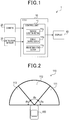
- FIG. 1 is a block diagram illustrating a configuration of an imaging system according to the present embodiment.
- An imaging system 1 according to the present embodiment is mounted to a vehicle to display an image ahead of the own vehicle on a display, and includes an ECU 10, a camera 20, a detection sensor 30, a display 40, and the like.
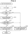
- Fig. 2 is a diagram illustrating an imaging region and imaging areas of the present embodiment.
- the camera 20 captures an image of an imaging region 110 provided in the forward direction of an own vehicle 100 through a wide-angle lens, and outputs a video signal indicating the image to the ECU 10.
- the imaging region 110 according to the present embodiment is made up of three imaging areas (a plurality of imaging areas), namely, a first imaging area 111, a second imaging area 112, and a third imaging area 113.
- the detection sensor 30 detects an object (e.g., a moving object such as a pedestrian or a vehicle, an obstacle on the road, a guardrail set up along the road, a traffic light, a utility pole, or the like) that is present in the imaging region 110 in the forward direction of the own vehicle 100.
- the detection sensor 30 includes a radar, a sonar, or the like, for example, and transmits a search wave and detects a reflected wave of the search wave to thereby detect a location, size, type, and the like of the object present ahead of the own vehicle 100.
- the detection sensor 30 then outputs a detection signal indicating detection results to the ECU 10.
- the detection sensor 30 may also include a stereo camera or the like, for example.
- the detection sensor 30 may also include the camera 20, and may analyze the image captured by the camera 20 to detect the object ahead of the own vehicle 100.
- the ECU 10 corresponds to the image generating device of the present embodiment, and includes a control unit 11 made up of a CPU, ROM, RAM, I/O, and the like.
- the CPU of the control unit 11 executes a program stored in the ROM to perform overall control of the ECU 10 and perform various processes.
- the CPU of the control unit 11 operates according to the program to serve as an obstacle detection section 11a, a display control section 11b, and a risk determination section 11c.
- the obstacle detection section 11a Based on a detection signal from the detection sensor 30, the obstacle detection section 11a detects a location, size, type, and the like of an object present ahead of the own vehicle 100.
- the display control section 11b Based on a video signal from the camera 20, the display control section 11b generates image data.
- the display control section 11b corrects the generated image data, and generates display image data for displaying the entire imaging region 110.
- the display control section 11b outputs a video signal for displaying the generated display image data to the display 40.
- the display 40 is a device made up of a liquid crystal display, an organic EL display, and the like, and displays an image on the basis of the video signal derived from the ECU 10.
- the risk determination section 11c determines a degree of risk that indicates a probability for an object present ahead of the own vehicle 100 to contact (i.e., collide against) the own vehicle 100.
- the imaging region 110 spread in the forward direction of the own vehicle 100 is in a sector shape having a center angle of 180° in plan view.
- the imaging region 110 is horizontally fanned out in the forward direction of the own vehicle 100.
- the imaging region 110 is made up of the three imaging areas, namely, the first, second, and third imaging areas 111, 112 and 113, each being formed into a sector shape.
- the first, second and third imaging areas 111, 112 and 113 are arranged in a row in a horizontal direction intersecting the forward direction of the camera 20.
- the center angle is not limited to 180°.
- the first imaging area 111 (right border area) positioned at the right end of the imaging region 110 has a center angle ⁇ a
- the camera 20 captures an image of the imaging region 110 through a wide-angle lens. Accordingly, the image directly generated from the video signal of the camera 20 is distorted in the right and left side portions.
- the ECU (image generating device) 10 of the present embodiment corrects the image data to generate display image data, and using the generated display image data as a basis, displays the image of the imaging region 110 on the display 40. In this case, the correction made by the ECU 10 is in conformity with the object detection results derived from the detection sensor 30.
- Fig. 3 shows a diagram illustrating a first display image (normal image) of the present embodiment.
- Fig. 3 shows an example of a pedestrian as an example of an object 120 detected by the detection sensor 30.
- the first imaging area 111 is referred to as a right border area 111
- the second imaging area 112 is referred to as a center area 112
- the third imaging area 113 is referred to as a left border area 113.
- the driver during driving has a difficulty in directly seeing the right and left border areas 111 and 113 compared to seeing the center area 112.
- the ECU 10 displays, on the display 40, a first display image (hereinafter referred to as normal image) 150 in which the right and left border areas 111 and 113 have higher visibility than the center area 112.
- normal image a first display image
- the ECU 10 allows the display 40 to display the images of the right and left border areas 111 and 113 in a display format easily visible to the driver (i.e., in an easy-to-see state).
- a center image region 152 of a normal image 150 the image of the center area 112 is displayed being reduced (hereinafter referred to as reduced state) relative to the images of the right and left border areas 111 and 113.
- Fig. 3 shows a display example in which an image has been corrected and reduced at a predetermined reduction ratio in a horizontal direction D orthogonal to a straight line P (center line) which evenly divides the center angle ⁇ b of the center area 112 into two (i.e., reduced in the right-and-left direction relative to the forward direction of the camera 20).
- Fig. 3 shows a display example in which images are not reduced (corrected) (i.e., in a state close to the vision obtained through the driver's direct visual recognition), to achieve higher visibility (i.e., to achieve easier visual recognition) for the driver than the display image of the center area 112 displayed in a reduced state.
- the display example shows a state in which images are corrected and reduced at a reduction ratio lower than that of the reduced state of the center area 112.
- the images of the right and left border areas 111 and 113 are displayed being enlarged relative to the image of the center area 112 where the object 120 is not present (i.e., displayed being relatively enlarged).
- the reduction degrees of the respective images of the imaging areas are adjusted such that the image of the imaging area where the object 120 is present is displayed in a more easy-to-see state than the images of other imaging areas, thereby correcting the image data.
- the display image data for entirely displaying the imaging region 110 is generated.
- the displayed state achieving high visibility to the driver is referred to as normal state, for the sake of convenience.
- the ECU 10 displays, on the display 40, a second display image in which the center area 112 achieves higher visibility than the right and left border areas 111 and 113 (hereinafter referred to as warning image).
- Fig. 4 shows a display example of when the object 120 is present in the center area 112.
- the image of the center area 112 where the object 120 is present is displayed in a normal state in a center image region 162 of a warning image (second display image) 160.
- a right image region 161 and a left image region 163 the images of the right and left border areas 111 and 113, respectively, are displayed in a reduced state.
- FIG. 5 a flowchart of Fig. 5 , hereinafter will be described an image displaying process in which the ECU (image generating device) 10 of the present embodiment generates an image of the imaging region 110 on the basis of a video signal derived from the camera 20, and displays the image on the display 40.
- the present process is cyclically performed by the CPU of the control unit 11 provided to the ECU 10.
- the CPU of the control unit 11 Based on the detection signal from the detection sensor 30, the CPU of the control unit 11 detects the location, size, type and the like of the object 120 present ahead of the own vehicle 100 (S200), and allows the process to proceed to S205. In this way, the CPU of the control unit 11 serves as the obstacle detection section 11a by performing the process of S200. Then, the CPU determines whether the object 120 is present ahead of the own vehicle 100 (S205). As a result, if the CPU determines that the object 120 is present ahead of the own vehicle 100 (YES at S205), the CPU allows the process to proceed to S210. On the other hand, if the CPU determines that the object 120 is not present ahead of the own vehicle 100 (NO at S205), the CPU allows the process to proceed to S225.
- the CPU determines whether the calculated barycentric position is in the center area 112 of the imaging region 110 (S215). Thus, if the CPU determines that the barycentric position is in the center area 112 (YES at S215), the CPU allows the process to proceed to S220 and displays the warning image 160 on the display 40. In this case, the CPU determines the center area 112 of the imaging region 110, where the object 120 is present, to be a target area which is to be displayed in an easy-to-see state.
- the CPU corrects the image data such that the images of the right and left border areas 111 and 113 of the imaging region 110 are displayed in a reduced state, while the image of the center area 112 where the object 120 is present is displayed in a normal state, and generates the display image data for entirely displaying the imaging region 110 (S220).
- the image of the center area 112 is displayed being enlarged compared to the images of the right and left border areas 111 and 113.
- the CPU displays the image of the center area 112 where the object 120 is present in a relatively enlarged manner, and displays the detected object 120 in an easily-visible display format (i.e., in an easy-to-see state).
- the CPU determines that the barycentric position is not in the center area 112 (NO at S215), the CPU allows the process to proceed to S225, and displays the normal image 150 on the display 40.
- the CPU determines the right and left border areas 111 and 113 of the imaging region 110, which are difficult to be directly visibly recognized, to be target areas which are to be displayed in an easy-to-see state.
- the CPU corrects the image data such that the image of the center area 112 of the imaging region 110 is displayed in a reduced state, while the images of the right and left border areas 111 and 113 are displayed in a normal state, and generates the display image data for entirely displaying the imaging region 110 (S225).
- the determination process at S215 may be performed based on the following determination conditions.
- the conditions include an entry condition which is defined to be a state where the object 120 is absent from the center area 112 of the imaging region 110, followed by new entry of the object 120 into the center area 112 of the imaging region 11.
- the conditions include a retreat condition which is defined to be a state where the object 120 is present in the center area 112, followed by movement of the object 120 out of the center area 112. Either of the entry and retreat conditions may be a condition more difficult to be met than the other condition.
- the entry condition of the object 120 may be defined, for example, to be a situation in which at least a part of the object region of the object 120 that has been present outside the center area 112 has come to be positioned in the center area 112.
- the retreat condition of the object 120 may be defined, for example, to be a situation in which the entire object region of the object 120 that has been present in the center area 112 has come to be positioned outside the center area 112, or a situation in which the barycentric position of the object 120 has come to be positioned outside the center area 112.
- the entry condition of the object 120 may be defined, for example, to be a situation in which the entire object region of the object 120 that has been present outside the center area 112 has come to be positioned in the center area 112, or a situation in which the barycentric position of the object 120 has come to be positioned in the center area 112.
- the retreat condition of the object 120 may be defined to be a situation in which at least a part of the object region of the object 120 that has been present in the center area 112 has come to be positioned outside the center area 112.
- the steps of S220 and S225 are performed as follows. If the CPU of the control unit 11 determines that the object 120 is not present in the center area 112, and the entry condition is met, the CPU performs the step of S220. On the other hand, if the entry condition is not met, the CPU performs the step of S225. If the CPU of the control unit 11 determines that the object 120 is present in the center area 112, and the retreat condition is not met, the CPU performs the step of S220. On the other hand, if the retreat condition is met, the CPU performs the step of S225.
- the CPU of the control unit 11 In the display step of S220, the CPU of the control unit 11 generates image data on the basis of a video signal derived from the camera 20, corrects the generated image data, and generates display image data for the warning image 160 (image displaying the center area 112 in a normal state, and the right and left border areas 111 and 113 in a reduced state). Resultantly, the CPU of the control unit 11 outputs a video signal for displaying the display image data to the display 40, causes the display 40 to display the warning image 160, and terminates the present process.
- the imaging system 1 provided with the image generating device of the present embodiment displays, on the display 40, an image that is an overview around the own vehicle 100. In doing so, if the object 120 is present in the center area 112, the imaging system 1 displays the warning image 160 in which the center area 112 is displayed in a normal state, and the right and left border areas 111 and 113 are displayed in a reduced state. If the object 120 is present in either of the right and left border areas 111 and 113, the imaging system 1 displays the normal image 150 in which the center area 112 is displayed in a reduced state, and the right and left border areas 111 and 113 are displayed in a normal state.
- the right border area 111, the center area 112, and the left border area 113 are each formed into a sector shape and arranged in a row in the horizontal direction D (right-and-left direction) relative to the forward direction of the camera 20.
- the imaging system 1 provided with the image generating device of the present embodiment displays the image of the imaging area where the object 120 is present in a normal state.
- the imaging system 1 displays the image of the imaging area where the object 120 is not present in a reduced state, after being corrected and reduced in the horizontal direction D (right-and-left direction) relative to the forward direction of the camera 20.
- the imaging system 1 provided with the image generating device of the present embodiment to display the image that is an overview around the own vehicle 100, and if the object 120 is present in the imaging area, to show the object 120 in a display format easily visually recognizable to the driver (i.e., in an easy-to-see state) in the displayed image.
- the images of the right and left border areas 111 and 113 are displayed being enlarged compared to the image of the center area 112. This enables the driver during driving to easily visually recognize the right and left border areas 111 and 113 that are difficult to be directly visually recognized.
- An imaging system 1 is configured similarly to that of the first embodiment, but differs therefrom in the following points.
- An ECU (image generating device) 10 of the present embodiment determines a degree of risk indicating a probability of an object 120 coming into contact with the own vehicle 100, on the basis of a predetermined criterion. Based on the determined degree of risk (i.e., determination results), the ECU 10 of the present embodiment selects a target area that is an imaging area to be displayed in an easy-to-see state, from among a plurality of imaging areas. In response to the results, the ECU 10 of the present embodiment selects either of the normal image 150 and the warning image 160 as a display image to be displayed on the display 40.
- the present embodiment differs from the first embodiment in that the CPU of the control unit 11 in the ECU 10 serves as the risk determination section 11c by performing a predetermined process.
- a distance between the own vehicle 100 and the object 120 is used as a criterion to determine a degree of risk to the own vehicle 100 posed by the object 120.
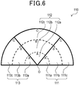
- Fig. 6 is a diagram illustrating an imaging region 110 and imaging areas 111, 112, and 113 of the present embodiment.
- a position relative to the own vehicle 100 can be indicated by a position in the coordinate spaces concentrically spreading from a center O of the imaging region 110. As shown in Fig.
- a degree of risk [4] is defined for 112a of the zone A closest to the own vehicle 100.
- a degree of risk [3] is defined for 112b of the zone B secondly closest to the own vehicle 100
- a degree of risk [2] is defined for 112c of the zone C farthest from the own vehicle 100.
- a degree of risk may be determined using a criterion, such as the moving direction or the moving speed of the object 120 identified based on the detection signal from the detection sensor 30, the type of the object 120 (i.e., pedestrian, vehicle, or guardrail), or the like.
- a criterion such as the moving direction or the moving speed of the object 120 identified based on the detection signal from the detection sensor 30, the type of the object 120 (i.e., pedestrian, vehicle, or guardrail), or the like.
- the determination method that uses a moving direction as a criterion the object 120 moving toward the own vehicle 100 may be determined to have a higher degree of risk than the object 120 moving in a direction departing from the own vehicle 100.
- another possible determination method may use a plurality of criteria to determine a degree of risk.
- a degree of risk for one object 120 may be determined first based on each of the criteria, and then a sum of the determined degrees of risk based on the criteria may be determined to be an ultimate degree of risk of the object 120.
- the CPU selects the type of the display image similarly to the first embodiment.
Description
- The present disclosure relates to an image generating technique.
- Conventionally known methods include adding a predetermined correction to distorted images captured around the own vehicle by a wide-angle camera, generating three undistorted images captured in the forward, leftward, and rightward directions of the wide-angle camera, and displaying the undistorted images, juxtaposed, on a screen (PTL 1).
- [PTL 1]
JP 2010-109483 A - The document
US 2009/010567 A1 discloses an image generating device according to the preamble of claim 1, and an image generating method according to the preamble of claim 5. - However, the driver's line of sight during driving is usually in the forward direction of the own vehicle. Accordingly, if the images around the own vehicle are merely displayed in an undistorted state, there is a probability that the driver cannot recognize an object present around the own vehicle.
- The present disclosure has an object of enabling a driver to easily recognize an object present around the own vehicle.
- An image generating device of the present disclosure includes an acquisition means, a determination means, a selection means, a generation means, and a display means. The acquisition means captures an image of an imaging region around an own vehicle with a camera through a wide-angle lens, and acquires image data, the imaging region being configured by a plurality of imaging areas. The determination means detects an object present around the own vehicle and determines whether the object is present in the imaging areas, on the basis of detection results. The selection means selects a target area to be displayed in an easy-to-see state from among the plurality of imaging areas, on the basis of determination results derived from the determination means. The generation means adjusts a reduction degree of an image of each imaging area such that the image of the target area is displayed in an easy-to-see state compared to the image of each imaging area, and corrects the image data to generate display image data for displaying the entire imaging region. The display means displays the display image data.
- With this configuration, the image generating device of the present disclosure displays an image offering a broad view around the own vehicle and displays, on the image thus displayed, an imaging area where the object is present in an easy-to-see state (high-visibility state). Therefore, the driver can easily recognize the object present around the own vehicle.
- The description set forth in the present section is for showing correspondency to the specific means described in the embodiments set forth below, and should not be construed as limiting the technical scope of the present disclosure.
-
-
Fig. 1 is a block diagram illustrating a configuration of an imaging system, according to a first embodiment. -
Fig. 2 is a diagram illustrating an imaging region and imaging areas, according to the first embodiment. -
Fig. 3 is a diagram illustrating a first display image (normal image), according to the first embodiment. -
Fig. 4 is a diagram illustrating a second display image (warning image), according the first embodiment. -
Fig. 5 is a flowchart illustrating an image displaying process, according to the first embodiment. -
Fig. 6 is a diagram illustrating an imaging region and imaging areas, according to a second embodiment. - With reference to the drawings, some embodiments of the present disclosure will hereinafter be described.
-
Fig. 1 is a block diagram illustrating a configuration of an imaging system according to the present embodiment. An imaging system 1 according to the present embodiment is mounted to a vehicle to display an image ahead of the own vehicle on a display, and includes anECU 10, acamera 20, adetection sensor 30, adisplay 40, and the like. -
Fig. 2 is a diagram illustrating an imaging region and imaging areas of the present embodiment. Thecamera 20 captures an image of animaging region 110 provided in the forward direction of anown vehicle 100 through a wide-angle lens, and outputs a video signal indicating the image to theECU 10. Theimaging region 110 according to the present embodiment is made up of three imaging areas (a plurality of imaging areas), namely, afirst imaging area 111, asecond imaging area 112, and athird imaging area 113. - Referring to
Fig. 1 again, thedetection sensor 30 detects an object (e.g., a moving object such as a pedestrian or a vehicle, an obstacle on the road, a guardrail set up along the road, a traffic light, a utility pole, or the like) that is present in theimaging region 110 in the forward direction of theown vehicle 100. Thedetection sensor 30 includes a radar, a sonar, or the like, for example, and transmits a search wave and detects a reflected wave of the search wave to thereby detect a location, size, type, and the like of the object present ahead of theown vehicle 100. Thedetection sensor 30 then outputs a detection signal indicating detection results to theECU 10. - Besides this, the
detection sensor 30 may also include a stereo camera or the like, for example. Thedetection sensor 30 may also include thecamera 20, and may analyze the image captured by thecamera 20 to detect the object ahead of theown vehicle 100. - The
ECU 10 corresponds to the image generating device of the present embodiment, and includes acontrol unit 11 made up of a CPU, ROM, RAM, I/O, and the like. The CPU of thecontrol unit 11 executes a program stored in the ROM to perform overall control of theECU 10 and perform various processes. The CPU of thecontrol unit 11 operates according to the program to serve as anobstacle detection section 11a, adisplay control section 11b, and arisk determination section 11c. - Based on a detection signal from the
detection sensor 30, theobstacle detection section 11a detects a location, size, type, and the like of an object present ahead of theown vehicle 100. - Based on a video signal from the
camera 20, thedisplay control section 11b generates image data. Thedisplay control section 11b corrects the generated image data, and generates display image data for displaying theentire imaging region 110. Thedisplay control section 11b outputs a video signal for displaying the generated display image data to thedisplay 40. Thedisplay 40 is a device made up of a liquid crystal display, an organic EL display, and the like, and displays an image on the basis of the video signal derived from theECU 10. - Based on the detection results from the
detection sensor 30, therisk determination section 11c determines a degree of risk that indicates a probability for an object present ahead of theown vehicle 100 to contact (i.e., collide against) theown vehicle 100. - An operation of the imaging system 1 will be described. In the following description, the right side and the left side relative to the traveling direction of the own vehicle 100 (hereinafter referred to as forward direction of the camera 20) are simply referred to as right and left, respectively.
- As shown in
Fig. 2 , theimaging region 110 spread in the forward direction of theown vehicle 100 is in a sector shape having a center angle of 180° in plan view. In other words, theimaging region 110 is horizontally fanned out in the forward direction of theown vehicle 100. Theimaging region 110 is made up of the three imaging areas, namely, the first, second, andthird imaging areas third imaging areas camera 20. The center angle is not limited to 180°. The first imaging area 111 (right border area) positioned at the right end of theimaging region 110 has a center angle θa, and the third imaging area 113 (left border area) positioned at the left end of theimaging region 110 has a center angle θc, the center angle θa being equal to the center angle θc (θa = θc). - Based on the image data acquired from the
camera 20, theECU 10 displays an image of theimaging region 110 on thedisplay 40. The display image displayed on thedisplay 40 is divided into three image segments (i.e., right image segment, center image segment, and left image segment) arranged in the right-and-left direction. The image in the first imaging area (right border area) 111 is displayed in the right image segment. The image in the second imaging area (center area) 112 is displayed in the center image segment. The image in the third imaging area (left border area) 113 is displayed in the left image segment. - The
camera 20 captures an image of theimaging region 110 through a wide-angle lens. Accordingly, the image directly generated from the video signal of thecamera 20 is distorted in the right and left side portions. In this regard, the ECU (image generating device) 10 of the present embodiment corrects the image data to generate display image data, and using the generated display image data as a basis, displays the image of theimaging region 110 on thedisplay 40. In this case, the correction made by theECU 10 is in conformity with the object detection results derived from thedetection sensor 30. -
Fig. 3 shows a diagram illustrating a first display image (normal image) of the present embodiment.Fig. 3 shows an example of a pedestrian as an example of anobject 120 detected by thedetection sensor 30. In the following description, for the sake of clarifying a positional relation between the imaging areas, thefirst imaging area 111 is referred to as aright border area 111, thesecond imaging area 112 is referred to as acenter area 112, and thethird imaging area 113 is referred to as aleft border area 113. The driver during driving has a difficulty in directly seeing the right and leftborder areas center area 112. If theobject 120 is not present in thecenter area 112, theECU 10 displays, on thedisplay 40, a first display image (hereinafter referred to as normal image) 150 in which the right and leftborder areas center area 112. In other words, if theobject 120 is not present in thecenter area 112, theECU 10 allows thedisplay 40 to display the images of the right and leftborder areas - In a
center image region 152 of anormal image 150, the image of thecenter area 112 is displayed being reduced (hereinafter referred to as reduced state) relative to the images of the right and leftborder areas Fig. 3 shows a display example in which an image has been corrected and reduced at a predetermined reduction ratio in a horizontal direction D orthogonal to a straight line P (center line) which evenly divides the center angle θb of thecenter area 112 into two (i.e., reduced in the right-and-left direction relative to the forward direction of the camera 20). - On the other hand, in a
right image region 151 and aleft image region 153 of thenormal image 150, the images of the right and leftborder areas center area 112.Fig. 3 shows a display example in which images are not reduced (corrected) (i.e., in a state close to the vision obtained through the driver's direct visual recognition), to achieve higher visibility (i.e., to achieve easier visual recognition) for the driver than the display image of thecenter area 112 displayed in a reduced state. In other words, the display example shows a state in which images are corrected and reduced at a reduction ratio lower than that of the reduced state of thecenter area 112. Specifically, in the example shown inFig. 3 , the images of the right and leftborder areas center area 112 where theobject 120 is not present (i.e., displayed being relatively enlarged). In this way, in the present embodiment, the reduction degrees of the respective images of the imaging areas are adjusted such that the image of the imaging area where theobject 120 is present is displayed in a more easy-to-see state than the images of other imaging areas, thereby correcting the image data. Thus, in the present embodiment, the display image data for entirely displaying theimaging region 110 is generated. In the following description, the displayed state achieving high visibility to the driver is referred to as normal state, for the sake of convenience. - In contrast, if the
object 120 is present in thecenter area 112, theECU 10 displays, on thedisplay 40, a second display image in which thecenter area 112 achieves higher visibility than the right and leftborder areas 111 and 113 (hereinafter referred to as warning image).Fig. 4 shows a display example of when theobject 120 is present in thecenter area 112. - As shown in
Fig. 4 , the image of thecenter area 112 where theobject 120 is present is displayed in a normal state in acenter image region 162 of a warning image (second display image) 160. On the other hand, in aright image region 161 and aleft image region 163, the images of the right and leftborder areas - Referring to a flowchart of
Fig. 5 , hereinafter will be described an image displaying process in which the ECU (image generating device) 10 of the present embodiment generates an image of theimaging region 110 on the basis of a video signal derived from thecamera 20, and displays the image on thedisplay 40. The present process is cyclically performed by the CPU of thecontrol unit 11 provided to theECU 10. - Based on the detection signal from the
detection sensor 30, the CPU of thecontrol unit 11 detects the location, size, type and the like of theobject 120 present ahead of the own vehicle 100 (S200), and allows the process to proceed to S205. In this way, the CPU of thecontrol unit 11 serves as theobstacle detection section 11a by performing the process of S200. Then, the CPU determines whether theobject 120 is present ahead of the own vehicle 100 (S205). As a result, if the CPU determines that theobject 120 is present ahead of the own vehicle 100 (YES at S205), the CPU allows the process to proceed to S210. On the other hand, if the CPU determines that theobject 120 is not present ahead of the own vehicle 100 (NO at S205), the CPU allows the process to proceed to S225. - If the CPU determines that the
object 120 is present ahead of theown vehicle 100, the CPU calculates the barycentric position of the detected object 120 (S210), and allows the process to proceed to S215. In this case, the CPU may calculate the barycentric position of theobject 120 by the following method, for example. Specifically, a region where the detectedobject 120 is present (hereinafter referred to as object region) is identified on the horizontal plane where theown vehicle 100 is present, and the center of the identified region is taken to be the barycentric position. - Then, the CPU determines whether the calculated barycentric position is in the
center area 112 of the imaging region 110 (S215). Thus, if the CPU determines that the barycentric position is in the center area 112 (YES at S215), the CPU allows the process to proceed to S220 and displays thewarning image 160 on thedisplay 40. In this case, the CPU determines thecenter area 112 of theimaging region 110, where theobject 120 is present, to be a target area which is to be displayed in an easy-to-see state. Thus, the CPU corrects the image data such that the images of the right and leftborder areas imaging region 110 are displayed in a reduced state, while the image of thecenter area 112 where theobject 120 is present is displayed in a normal state, and generates the display image data for entirely displaying the imaging region 110 (S220). Thus, the image of thecenter area 112 is displayed being enlarged compared to the images of the right and leftborder areas center area 112 where theobject 120 is present in a relatively enlarged manner, and displays the detectedobject 120 in an easily-visible display format (i.e., in an easy-to-see state). On the other hand, if the CPU determines that the barycentric position is not in the center area 112 (NO at S215), the CPU allows the process to proceed to S225, and displays thenormal image 150 on thedisplay 40. In this case, the CPU determines the right and leftborder areas imaging region 110, which are difficult to be directly visibly recognized, to be target areas which are to be displayed in an easy-to-see state. Thus, the CPU corrects the image data such that the image of thecenter area 112 of theimaging region 110 is displayed in a reduced state, while the images of the right and leftborder areas border areas center area 112. In other words, the CPU displays the right and leftborder areas center area 112, in an easily-visible display format (i.e., in an easy-to-see state). In this way, the CPU of thecontrol unit 11 serves as thedisplay control section 11b by performing the steps of S220 and S225. - The determination process at S215 may be performed based on the following determination conditions. Specifically, the conditions include an entry condition which is defined to be a state where the
object 120 is absent from thecenter area 112 of theimaging region 110, followed by new entry of theobject 120 into thecenter area 112 of theimaging region 11. On the other hand, the conditions include a retreat condition which is defined to be a state where theobject 120 is present in thecenter area 112, followed by movement of theobject 120 out of thecenter area 112. Either of the entry and retreat conditions may be a condition more difficult to be met than the other condition. - Specifically, the entry condition of the
object 120 may be defined, for example, to be a situation in which at least a part of the object region of theobject 120 that has been present outside thecenter area 112 has come to be positioned in thecenter area 112. The retreat condition of theobject 120 may be defined, for example, to be a situation in which the entire object region of theobject 120 that has been present in thecenter area 112 has come to be positioned outside thecenter area 112, or a situation in which the barycentric position of theobject 120 has come to be positioned outside thecenter area 112. - Alternatively, the entry condition of the
object 120 may be defined, for example, to be a situation in which the entire object region of theobject 120 that has been present outside thecenter area 112 has come to be positioned in thecenter area 112, or a situation in which the barycentric position of theobject 120 has come to be positioned in thecenter area 112. The retreat condition of theobject 120 may be defined to be a situation in which at least a part of the object region of theobject 120 that has been present in thecenter area 112 has come to be positioned outside thecenter area 112. - If the determination process at S215 is performed based on such determination conditions, the steps of S220 and S225 are performed as follows. If the CPU of the
control unit 11 determines that theobject 120 is not present in thecenter area 112, and the entry condition is met, the CPU performs the step of S220. On the other hand, if the entry condition is not met, the CPU performs the step of S225. If the CPU of thecontrol unit 11 determines that theobject 120 is present in thecenter area 112, and the retreat condition is not met, the CPU performs the step of S220. On the other hand, if the retreat condition is met, the CPU performs the step of S225. - Thus, the ECU (image generating device) 10 of the present embodiment can prevent frequent switching between the
normal image 150 and thewarning image 160 displayed on the display 40 (i.e., types of displayed image) when theobject 120 is present near a border of thecenter area 112. - In the display step of S220, the CPU of the
control unit 11 generates image data on the basis of a video signal derived from thecamera 20, corrects the generated image data, and generates display image data for the warning image 160 (image displaying thecenter area 112 in a normal state, and the right and leftborder areas control unit 11 outputs a video signal for displaying the display image data to thedisplay 40, causes thedisplay 40 to display thewarning image 160, and terminates the present process. - If the
object 120 is also present in either of the right and leftborder areas center area 112, the CPU of thecontrol unit 11 may perform the following display process. The CPU generates display image data for thewarning image 160 to provide a normal state display for thecenter area 112 and the border area whereobjects 120 are present, and to provide a reduced state display for the border area where theobject 120 is not present. - On the other hand, in the display step of S225, the CPU of the
control unit 11 generates image data on the basis of a video signal derived from thecamera 20, corrects the generated image data, and generates display image data for the normal image 150 (image displaying thecenter area 112 in a reduced state, and the right and leftborder areas control unit 11 outputs a video signal for displaying the display image data to thedisplay 40, causes thedisplay 40 to display thenormal image 150, and terminates the present process. - The imaging system 1 provided with the image generating device of the present embodiment displays, on the
display 40, an image that is an overview around theown vehicle 100. In doing so, if theobject 120 is present in thecenter area 112, the imaging system 1 displays thewarning image 160 in which thecenter area 112 is displayed in a normal state, and the right and leftborder areas object 120 is present in either of the right and leftborder areas normal image 150 in which thecenter area 112 is displayed in a reduced state, and the right and leftborder areas object 120 is present is shown in an easy-to-see state (high-visibility state) in the displayed image. Accordingly, the driver can easily recognize theobject 120 present in the imaging region 110 (i.e., object present around the own vehicle 100). - In the
imaging region 110 of the present embodiment, theright border area 111, thecenter area 112, and theleft border area 113 are each formed into a sector shape and arranged in a row in the horizontal direction D (right-and-left direction) relative to the forward direction of thecamera 20. The imaging system 1 provided with the image generating device of the present embodiment displays the image of the imaging area where theobject 120 is present in a normal state. On the other hand, the imaging system 1 displays the image of the imaging area where theobject 120 is not present in a reduced state, after being corrected and reduced in the horizontal direction D (right-and-left direction) relative to the forward direction of thecamera 20. This enables the imaging system 1 provided with the image generating device of the present embodiment to display the image that is an overview around theown vehicle 100, and if theobject 120 is present in the imaging area, to show theobject 120 in a display format easily visually recognizable to the driver (i.e., in an easy-to-see state) in the displayed image. - In the present embodiment, if the
object 120 is absent from the areas in theimaging region 110, or if theobject 120 is present only in theright border area 111 or theleft border area 113, the images of the right and leftborder areas center area 112. This enables the driver during driving to easily visually recognize the right and leftborder areas - An imaging system 1 according to the present embodiment is configured similarly to that of the first embodiment, but differs therefrom in the following points. An ECU (image generating device) 10 of the present embodiment determines a degree of risk indicating a probability of an
object 120 coming into contact with theown vehicle 100, on the basis of a predetermined criterion. Based on the determined degree of risk (i.e., determination results), theECU 10 of the present embodiment selects a target area that is an imaging area to be displayed in an easy-to-see state, from among a plurality of imaging areas. In response to the results, theECU 10 of the present embodiment selects either of thenormal image 150 and thewarning image 160 as a display image to be displayed on thedisplay 40. Thus, the present embodiment differs from the first embodiment in that the CPU of thecontrol unit 11 in theECU 10 serves as therisk determination section 11c by performing a predetermined process. - Hereinafter will be described a method of determining a degree of risk performed by the
ECU 10 of the present embodiment. In an example of the determination method of the present embodiment, a distance between theown vehicle 100 and theobject 120 is used as a criterion to determine a degree of risk to theown vehicle 100 posed by theobject 120.Fig. 6 is a diagram illustrating animaging region 110 andimaging areas Fig. 6 , a position relative to theown vehicle 100 can be indicated by a position in the coordinate spaces concentrically spreading from a center O of theimaging region 110. As shown inFig. 6 , theimaging areas own vehicle 100 to theobject 120. The zones are allocated and correlated to (i.e., defined with) respective degrees of risk, according to predetermined criteria. Accordingly, the degree of risk to theown vehicle 100 posed by theobject 120 present in each of theimaging areas object 120 is located. - A specific example of defining degrees of risk in the zones is set forth below. In the present embodiment, the degree of risk indicating a probability of the
object 120 coming into contact with theown vehicle 100 during travelling is defined with four grades on the basis of the relative distance between theown vehicle 100 and theobject 120. For example, in the right and leftborder areas own vehicle 100. A degree of risk [2] is defined for 111b and 113b of the zone B secondly closest to theown vehicle 100, and a degree of risk [1] is defined for 111c and 113c of the zone C farthest from theown vehicle 100. In thecenter area 112, a degree of risk [4] is defined for 112a of the zone A closest to theown vehicle 100. A degree of risk [3] is defined for 112b of the zone B secondly closest to theown vehicle 100, and a degree of risk [2] is defined for 112c of the zone C farthest from theown vehicle 100. In this way, it is ensured in the present embodiment that a position closer to theown vehicle 100 is set to a value indicating a higher degree of risk, while a position farther from theown vehicle 100 is set to a value indicating a lower degree of risk. Thus, in the present embodiment, the degree of risk defined for the zone where theobject 120 is present is determined to be a degree of risk to theown vehicle 100 posed by theobject 120. - The method of determining a degree of risk is not limited to the above method. For example, as another determination method, a degree of risk may be determined using a criterion, such as the moving direction or the moving speed of the
object 120 identified based on the detection signal from thedetection sensor 30, the type of the object 120 (i.e., pedestrian, vehicle, or guardrail), or the like. Specifically, in the determination method that uses a moving direction as a criterion, theobject 120 moving toward theown vehicle 100 may be determined to have a higher degree of risk than theobject 120 moving in a direction departing from theown vehicle 100. In the determination method that uses a moving speed as a criterion, theobject 120 moving at a speed of not less than a predetermined value may be determined to have a higher degree of risk than theobject 120 moving otherwise. In the determination method that uses the type of theobject 120 as a criterion, theobject 120 that is a pedestrian, a bicycle, or a motorcycle may be determined to have a higher degree of risk than theobject 120 that is a four-wheel vehicle, such as a standard-sized automobile or a large-sized automobile. - Furthermore, in addition to the method of determining a degree of risk on the basis of one criterion as described above, another possible determination method may use a plurality of criteria to determine a degree of risk. In this case, a degree of risk for one
object 120 may be determined first based on each of the criteria, and then a sum of the determined degrees of risk based on the criteria may be determined to be an ultimate degree of risk of theobject 120. - At S210 of the image displaying process of the present embodiment, the CPU of the
control unit 11 provided to theECU 10 determines a degree of risk to theown vehicle 100 posed by the detectedobject 120, in addition to performing the process shown in the first embodiment (the process of calculating the barycentric position of the object 120). At the subsequent S215, the CPU selects a target area to be displayed in an easy-to-see state, from among the plurality of imaging areas, on the basis of the imaging area where theobject 120 is present and the degree of risk posed by theobject 120. Then, based on the results, the CPU selects the type of the display image (thenormal image 150 or the warning image 160). - In this case, if the
object 120 is present only in one imaging area among thecenter area 112 and the right and leftborder areas - On the other hand, if
objects 120 are present in a plurality of imaging areas, the CPU calculates a sum of the degrees of risk of all the detectedobjects 120 for each of the imaging areas where theobjects 120 are present. Thus, if the sum of the degrees of risk calculated for thecenter area 112 is equal to or greater than a predetermined value, for example, the process proceeds to S220 where thewarning image 160 is displayed. On the other hand, if the sum of the degrees of risk is less than the predetermined value, the process may proceed to S225 to display thenormal image 150. If the sum of the degrees of risk calculated for thecenter area 112 is larger than the sum of the degrees of risk calculated for the right and leftborder areas - In the imaging system 1 provided with the image generating device of the present embodiment, the following advantageous effects can be obtained, in addition to those obtained in the first embodiment. Specifically, if a plurality of
objects 120 are present in theimaging region 110, the type of display image is switched based on not only the results of determination as to which of the imaging areas of theimaging region 110 the detectedobjects 120 are present, but also the results of determination on the degree of risk to theown vehicle 100 posed by theobjects 120. This enables the imaging system 1 provided with the image generating device of the present embodiment to display, in an enlarged manner, the imaging area where theobject 120 with a high probability of contacting the own vehicle 100 (degree of risk) is present, thereby drawing the driver's attention. - The image generating device of the present disclosure has so far been described. However, the present disclosure is not limited to the embodiments described above but can be implemented in various modes.
- (1) In the first and second embodiments, the
imaging region 110 is provided in the forward direction of theown vehicle 100, but is not limited thereto. In an embodiment, for example, theimaging region 110 may be provided in the rearward direction or the lateral direction of theown vehicle 100. - In the first and second embodiments, the
imaging region 110 is designed to have a sector shape, but is not limited thereto. In an embodiment, theimaging region 110 may be designed, for example, to have a shape elongated in the horizontal direction D relative to the forward direction of thecamera 20. Moreover, theimaging region 110 may be made up of two, or four or more imaging areas arranged in a row in the horizontal direction D relative to the forward direction of thecamera 20. In this case, the imaging area that can be directly and easily seen by the driver (area of high visibility) during driving is treated similarly to thecenter area 112 of the first and second embodiments. Further, the imaging area difficult to be directly seen (area of low visibility) may be treated similarly to the right and leftborder areas - If the
imaging region 110 is provided in the rearward direction of theown vehicle 100, the imaging area immediately behind theown vehicle 100 is taken to be thecenter area 112. Further, the imaging areas on the right and left sides of thecenter area 112 may be taken to be the right and leftborder areas center image region 162 of thewarning image 160 may be made larger than in the case where theimaging region 110 is provided in the forward direction of theown vehicle 100, so that thecenter area 112 is displayed in a more enlarged manner. The embodiment of such a configuration can achieve advantageous effects similar to those of the first and second embodiments. - (2) In an embodiment, the functions of one component of the first and second embodiments may be distributed to a plurality of components, or the functions of a plurality of components may be integrated into one component. In an embodiment, at least a part of the configuration of the first and second embodiments may be replaced by a known configuration having a similar function. In an embodiment, a part of the configuration of the first and second embodiments may be omitted. In an embodiment, at least a part of the configuration of the first or second embodiment may be added to, or replaced by, the configuration of another embodiment. The technique of the present disclosure should encompass any mode based on the technical idea which is specified by only the wordings used in the embodiments.
- (3) Besides the modes described in the above embodiments, the imaging system 1 of the present disclosure may also be realized in various modes, such as the components of the imaging system 1, a program for allowing a computer to function as the imaging system 1, a medium recording the program, and a method for realizing the image displaying process.
- Correspondency between the terms used in the description of the above embodiments and the terms used in the description of the claims are set forth below. The
ECU 10 provided to the imaging system 1 of the foregoing embodiments corresponds to the image generating device. S200 to S215 of the image displaying process serving as theobstacle detection section 11a of thecontrol unit 11 correspond to the determination means. S220 and S225 of the image displaying process serving as thedisplay control section 11b of thecontrol unit 11 correspond to the acquisition means, the selection means, the generation means, and the display means. - The
center area 112 of theimaging region 110 corresponds to the easy-to-see area, and the right and leftborder areas imaging region 110 correspond to the difficult-to-see area. - 1: Imaging system, 10: ECU, 11: Control unit, 11a: Obstacle detection section, 11b: Display control section, 20: Camera, 30: Detection sensor, 40: Display, 100: Own vehicle, 110: Imaging region, 111: Right border area, 112: Center area, 113: Left border area.
Claims (5)
- An image generating device (10) comprising:an acquisition means (S220, S225) for capturing an image of an imaging region (110) around an own vehicle (100) with a camera (20) through a wide-angle lens, and acquiring image data, the imaging region being configured by a plurality of imaging areas (111 to 113);a determination means (S200 to S215) for detecting an object (120) present around the own vehicle and determining whether the object is present in the imaging areas, on the basis of detection results;a selection means (S220, S225) for selecting a target area to be displayed in an easy-to-see state from among the plurality of imaging areas, on the basis of determination results derived from the determination means;a generation means (S220, S225) for adjusting a reduction degree of an image of at least one imaging area in the plurality of imaging areas such that the image of the target area is displayed in an easy-to-see state compared to the image of at least one remaining imaging area, and correcting the image data to generate display image data for displaying the entire imaging region; anda display means (S220, S225) for displaying the display image data,characterized in that:the image generating device is configured such that the image of the right and left areas as target areas are displayed being enlarged compared to the image of the center area as the remaining imaging area.the imaging region horizontally extends around the own vehicle,the imaging areas are arranged in a row in a horizontal direction intersecting a forward direction of the camera and include a center area (112) and right and left areas (111, 113),when the determining means determines that the object is not present in any of the imaging areas,the selection means is configured to select the right and left areas as imaging areas that are difficult for a driver to directly see during driving and determines such selected right and left areas to be a difficult-to-see areas, from among the plurality of imaging areas, and the selection means is further configured to set the selected right and left areas as target areas, and
- The image generating device according to claim 1, wherein
the generation means adjusts a horizontal reduction degree of the image of each imaging area in correcting the image data. - The image generating device according to claim 1 or 2, wherein
the determination means determines a degree of risk indicating a probability of the object coming into contact with the own vehicle, and
the selection means selects the target area on the basis of the degree of risk. - The image generating device according to any one of claims 1 to 3, wherein
an imaging area that is easy for the driver to directly see during driving is determined to be an easy-to-see area, from among the plurality of imaging areas,
the determination means determines an entry condition that is a condition in which the object has newly entered the easy-to-see area, and determines a retreat condition that is a condition in which the object present in the easy-to-see area has moved out of the area, and
either one of the entry condition and the retreat condition is more difficult to be met than the other condition. - An image generating method in an image generating device, comprising:an acquisition step (S220, S225) of capturing an image of an imaging region (110) around an own vehicle (100) with a camera (20) through a wide-angle lens, and acquiring image data, the imaging region being configured by a plurality of imaging areas (111 to 113);a determination step (S200 to S215) of detecting an object (120) present around the own vehicle and determining whether the object is present in the imaging areas, on the basis of detection results;a selection step (S220, S225) of selecting a target area to be displayed in an easy-to-see state from among the plurality of imaging areas, on the basis of determination results derived from the determination step;a generation step (S220, S225) of adjusting a reduction degree of an image of at least one imaging area in the plurality of imaging areas such that the image of the target area is displayed in an easy-to-see state compared to the image of at least one remaining imaging area, and correcting the image data to generate display image data for displaying the entire imaging region; anda display step (S220, S225) of displaying the display image data, whereincharacterized in that:the imaging region horizontally extends around the own vehicle,the imaging areas are arranged in a row in a horizontal direction intersecting a forward direction of the camera and include a center area (112) and right and left areas (111, 113),when the determination step determines that the object is not present in any of the imaging areas,the selection step selects the right and left areas as imaging areas that is difficult for a driver to directly see during driving, wherein such selected right and left areas are determined to be difficult-to-see areas, from among the plurality of imaging areas, and the selection step further sets the selected right and left areas as target areas, andimages of the right and left areas as the target areas are displayed being enlarged compared to the image of the center area as the remaining imaging area.
Applications Claiming Priority (2)
| Application Number | Priority Date | Filing Date | Title |
|---|---|---|---|
| JP2014249105A JP6398675B2 (en) | 2014-12-09 | 2014-12-09 | Image generation device |
| PCT/JP2015/080506 WO2016092967A1 (en) | 2014-12-09 | 2015-10-29 | Image generation device and image generation method |
Publications (3)
| Publication Number | Publication Date |
|---|---|
| EP3232400A1 EP3232400A1 (en) | 2017-10-18 |
| EP3232400A4 EP3232400A4 (en) | 2017-11-01 |
| EP3232400B1 true EP3232400B1 (en) | 2019-04-03 |
Family
ID=56107162
Family Applications (1)
| Application Number | Title | Priority Date | Filing Date |
|---|---|---|---|
| EP15868180.9A Active EP3232400B1 (en) | 2014-12-09 | 2015-10-29 | Image generation device and image generation method |
Country Status (5)
| Country | Link |
|---|---|
| US (1) | US10266114B2 (en) |
| EP (1) | EP3232400B1 (en) |
| JP (1) | JP6398675B2 (en) |
| CN (1) | CN107004250B (en) |
| WO (1) | WO2016092967A1 (en) |
Families Citing this family (6)
| Publication number | Priority date | Publication date | Assignee | Title |
|---|---|---|---|---|
| JP6623906B2 (en) * | 2015-09-08 | 2019-12-25 | 株式会社Jvcケンウッド | VEHICLE DISPLAY AND VEHICLE DISPLAY METHOD |
| JP6551336B2 (en) * | 2016-08-12 | 2019-07-31 | 株式会社デンソー | Peripheral audit equipment |
| JP6332383B2 (en) * | 2016-09-29 | 2018-05-30 | マツダ株式会社 | Vehicle target detection system |
| JP6649914B2 (en) * | 2017-04-20 | 2020-02-19 | 株式会社Subaru | Image display device |
| WO2020085101A1 (en) * | 2018-10-23 | 2020-04-30 | ソニーセミコンダクタソリューションズ株式会社 | Image processing device, image processing method, and program |
| US11508156B2 (en) * | 2019-12-27 | 2022-11-22 | Magna Electronics Inc. | Vehicular vision system with enhanced range for pedestrian detection |
Family Cites Families (20)
| Publication number | Priority date | Publication date | Assignee | Title |
|---|---|---|---|---|
| JPH02225628A (en) * | 1989-02-28 | 1990-09-07 | Kawasaki Steel Corp | Pretreatment of sintering raw material |
| JPH06227318A (en) * | 1993-02-08 | 1994-08-16 | Hitachi Ltd | Rearview monitoring device of vehicle and method thereof |
| JPH07288586A (en) * | 1994-04-18 | 1995-10-31 | Toshiba Corp | Electronic exchange system |
| JP4774603B2 (en) * | 2001-02-02 | 2011-09-14 | 日産自動車株式会社 | Vehicle display device |
| JP4010224B2 (en) * | 2002-10-23 | 2007-11-21 | トヨタ自動車株式会社 | Vehicle periphery monitoring device |
| JP2004304415A (en) * | 2003-03-31 | 2004-10-28 | Mazda Motor Corp | Monitor apparatus for vehicle |
| JP2007237785A (en) * | 2006-03-06 | 2007-09-20 | National Univ Corp Shizuoka Univ | On-vehicle information presentation system |
| JP4961160B2 (en) * | 2006-04-18 | 2012-06-27 | パナソニック株式会社 | Vehicle surroundings confirmation device |
| JP4855158B2 (en) | 2006-07-05 | 2012-01-18 | 本田技研工業株式会社 | Driving assistance device |
| JP4955471B2 (en) * | 2007-07-02 | 2012-06-20 | 株式会社デンソー | Image display device and in-vehicle image display device |
| JP2010109483A (en) | 2008-10-28 | 2010-05-13 | Honda Motor Co Ltd | Vehicle-surroundings displaying method |
| JP2010116086A (en) * | 2008-11-14 | 2010-05-27 | Alpine Electronics Inc | On-vehicle display, display method, and display program |
| US8988525B2 (en) * | 2009-08-27 | 2015-03-24 | Robert Bosch Gmbh | System and method for providing guidance information to a driver of a vehicle |
| JP5480917B2 (en) * | 2010-01-14 | 2014-04-23 | 本田技研工業株式会社 | Vehicle periphery monitoring device |
| US9321399B2 (en) * | 2010-03-01 | 2016-04-26 | Honda Motor Co., Ltd. | Surrounding area monitoring device for vehicle |
| EP2763405B1 (en) | 2011-09-29 | 2017-06-28 | Toyota Jidosha Kabushiki Kaisha | Image display device and image display method |
| WO2013067082A1 (en) * | 2011-11-01 | 2013-05-10 | Magna Mirrors Of America, Inc. | Vision system with door mounted exterior mirror and display |
| US10457209B2 (en) | 2012-02-22 | 2019-10-29 | Magna Electronics Inc. | Vehicle vision system with multi-paned view |
| US10493916B2 (en) | 2012-02-22 | 2019-12-03 | Magna Electronics Inc. | Vehicle camera system with image manipulation |
| KR20170036077A (en) * | 2014-07-24 | 2017-03-31 | 엠.브루베이커 커티스 | Systems, methods, and devices for generating critical mass in a mobile advertising, media, and communications platform |
-
2014
- 2014-12-09 JP JP2014249105A patent/JP6398675B2/en active Active
-
2015
- 2015-10-29 US US15/534,435 patent/US10266114B2/en active Active
- 2015-10-29 EP EP15868180.9A patent/EP3232400B1/en active Active
- 2015-10-29 WO PCT/JP2015/080506 patent/WO2016092967A1/en active Application Filing
- 2015-10-29 CN CN201580067234.0A patent/CN107004250B/en active Active
Non-Patent Citations (1)
| Title |
|---|
| None * |
Also Published As
| Publication number | Publication date |
|---|---|
| WO2016092967A1 (en) | 2016-06-16 |
| CN107004250B (en) | 2020-10-23 |
| US10266114B2 (en) | 2019-04-23 |
| JP6398675B2 (en) | 2018-10-03 |
| US20170368993A1 (en) | 2017-12-28 |
| EP3232400A4 (en) | 2017-11-01 |
| CN107004250A (en) | 2017-08-01 |
| EP3232400A1 (en) | 2017-10-18 |
| JP2016110501A (en) | 2016-06-20 |
Similar Documents
| Publication | Publication Date | Title |
|---|---|---|
| EP3232400B1 (en) | Image generation device and image generation method | |
| US10311618B2 (en) | Virtual viewpoint position control device and virtual viewpoint position control method | |
| US10229594B2 (en) | Vehicle warning device | |
| US8441536B2 (en) | Vehicle periphery displaying apparatus | |
| EP2544161B1 (en) | Surrounding area monitoring device for vehicle | |
| US8354944B2 (en) | Night vision device | |
| JP6074137B2 (en) | Vehicle surrounding information providing system and method | |
| US20150015712A1 (en) | Driving assistance device and driving assistance method | |
| JP6379779B2 (en) | Vehicle display device | |
| JP5712119B2 (en) | Pedestrian notification device for vehicles | |
| JP2018097704A (en) | Attention alerting device for vehicle | |
| US8370055B2 (en) | Driver assistance system | |
| JP6264037B2 (en) | Vehicle information display device and vehicle information display method | |
| US10099617B2 (en) | Driving assistance device and driving assistance method | |
| JP2012527681A (en) | Lane departure detection method and apparatus using vehicle periphery image | |
| US10609337B2 (en) | Image processing apparatus | |
| KR20140144905A (en) | Parking assistance system | |
| EP3772719B1 (en) | Image processing apparatus, image processing method, and image processing program | |
| JP2006042147A (en) | Cognitive support device for car | |
| CN113060156B (en) | Vehicle surroundings monitoring device, vehicle surroundings monitoring method, and program | |
| JPH11264868A (en) | Display device for vehicle | |
| JP3988551B2 (en) | Vehicle perimeter monitoring device | |
| JP2007182201A (en) | Lane change assistance device | |
| JP6476644B2 (en) | Cognitive assist device | |
| US10926700B2 (en) | Image processing device |
Legal Events
| Date | Code | Title | Description |
|---|---|---|---|
| STAA | Information on the status of an ep patent application or granted ep patent |
Free format text: STATUS: THE INTERNATIONAL PUBLICATION HAS BEEN MADE |
|
| PUAI | Public reference made under article 153(3) epc to a published international application that has entered the european phase |
Free format text: ORIGINAL CODE: 0009012 |
|
| STAA | Information on the status of an ep patent application or granted ep patent |
Free format text: STATUS: REQUEST FOR EXAMINATION WAS MADE |
|
| 17P | Request for examination filed |
Effective date: 20170518 |
|
| AK | Designated contracting states |
Kind code of ref document: A1 Designated state(s): AL AT BE BG CH CY CZ DE DK EE ES FI FR GB GR HR HU IE IS IT LI LT LU LV MC MK MT NL NO PL PT RO RS SE SI SK SM TR |
|
| AX | Request for extension of the european patent |
Extension state: BA ME |
|
| STAA | Information on the status of an ep patent application or granted ep patent |
Free format text: STATUS: EXAMINATION IS IN PROGRESS |
|
| A4 | Supplementary search report drawn up and despatched |
Effective date: 20171002 |
|
| RIC1 | Information provided on ipc code assigned before grant |
Ipc: G06T 1/00 20060101AFI20170926BHEP Ipc: H04N 7/18 20060101ALI20170926BHEP Ipc: G08G 1/16 20060101ALI20170926BHEP Ipc: B60R 1/00 20060101ALI20170926BHEP |
|
| 17Q | First examination report despatched |
Effective date: 20171019 |
|
| DAV | Request for validation of the european patent (deleted) | ||
| DAX | Request for extension of the european patent (deleted) | ||
| GRAP | Despatch of communication of intention to grant a patent |
Free format text: ORIGINAL CODE: EPIDOSNIGR1 |
|
| STAA | Information on the status of an ep patent application or granted ep patent |
Free format text: STATUS: GRANT OF PATENT IS INTENDED |
|
| INTG | Intention to grant announced |
Effective date: 20181210 |
|
| GRAS | Grant fee paid |
Free format text: ORIGINAL CODE: EPIDOSNIGR3 |
|
| GRAA | (expected) grant |
Free format text: ORIGINAL CODE: 0009210 |
|
| STAA | Information on the status of an ep patent application or granted ep patent |
Free format text: STATUS: THE PATENT HAS BEEN GRANTED |
|
| AK | Designated contracting states |
Kind code of ref document: B1 Designated state(s): AL AT BE BG CH CY CZ DE DK EE ES FI FR GB GR HR HU IE IS IT LI LT LU LV MC MK MT NL NO PL PT RO RS SE SI SK SM TR |
|
| REG | Reference to a national code |
Ref country code: GB Ref legal event code: FG4D |
|
| REG | Reference to a national code |
Ref country code: CH Ref legal event code: EP Ref country code: AT Ref legal event code: REF Ref document number: 1116666 Country of ref document: AT Kind code of ref document: T Effective date: 20190415 |
|
| REG | Reference to a national code |
Ref country code: DE Ref legal event code: R096 Ref document number: 602015027824 Country of ref document: DE |
|
| REG | Reference to a national code |
Ref country code: IE Ref legal event code: FG4D |
|
| REG | Reference to a national code |
Ref country code: NL Ref legal event code: MP Effective date: 20190403 |
|
| REG | Reference to a national code |
Ref country code: LT Ref legal event code: MG4D |
|
| REG | Reference to a national code |
Ref country code: AT Ref legal event code: MK05 Ref document number: 1116666 Country of ref document: AT Kind code of ref document: T Effective date: 20190403 |
|
| PG25 | Lapsed in a contracting state [announced via postgrant information from national office to epo] |
Ref country code: NL Free format text: LAPSE BECAUSE OF FAILURE TO SUBMIT A TRANSLATION OF THE DESCRIPTION OR TO PAY THE FEE WITHIN THE PRESCRIBED TIME-LIMIT Effective date: 20190403 |
|
| PG25 | Lapsed in a contracting state [announced via postgrant information from national office to epo] |
Ref country code: LT Free format text: LAPSE BECAUSE OF FAILURE TO SUBMIT A TRANSLATION OF THE DESCRIPTION OR TO PAY THE FEE WITHIN THE PRESCRIBED TIME-LIMIT Effective date: 20190403 Ref country code: SE Free format text: LAPSE BECAUSE OF FAILURE TO SUBMIT A TRANSLATION OF THE DESCRIPTION OR TO PAY THE FEE WITHIN THE PRESCRIBED TIME-LIMIT Effective date: 20190403 Ref country code: FI Free format text: LAPSE BECAUSE OF FAILURE TO SUBMIT A TRANSLATION OF THE DESCRIPTION OR TO PAY THE FEE WITHIN THE PRESCRIBED TIME-LIMIT Effective date: 20190403 Ref country code: AL Free format text: LAPSE BECAUSE OF FAILURE TO SUBMIT A TRANSLATION OF THE DESCRIPTION OR TO PAY THE FEE WITHIN THE PRESCRIBED TIME-LIMIT Effective date: 20190403 Ref country code: PT Free format text: LAPSE BECAUSE OF FAILURE TO SUBMIT A TRANSLATION OF THE DESCRIPTION OR TO PAY THE FEE WITHIN THE PRESCRIBED TIME-LIMIT Effective date: 20190803 Ref country code: CZ Free format text: LAPSE BECAUSE OF FAILURE TO SUBMIT A TRANSLATION OF THE DESCRIPTION OR TO PAY THE FEE WITHIN THE PRESCRIBED TIME-LIMIT Effective date: 20190403 Ref country code: ES Free format text: LAPSE BECAUSE OF FAILURE TO SUBMIT A TRANSLATION OF THE DESCRIPTION OR TO PAY THE FEE WITHIN THE PRESCRIBED TIME-LIMIT Effective date: 20190403 Ref country code: NO Free format text: LAPSE BECAUSE OF FAILURE TO SUBMIT A TRANSLATION OF THE DESCRIPTION OR TO PAY THE FEE WITHIN THE PRESCRIBED TIME-LIMIT Effective date: 20190703 Ref country code: HR Free format text: LAPSE BECAUSE OF FAILURE TO SUBMIT A TRANSLATION OF THE DESCRIPTION OR TO PAY THE FEE WITHIN THE PRESCRIBED TIME-LIMIT Effective date: 20190403 |
|
| PG25 | Lapsed in a contracting state [announced via postgrant information from national office to epo] |
Ref country code: BG Free format text: LAPSE BECAUSE OF FAILURE TO SUBMIT A TRANSLATION OF THE DESCRIPTION OR TO PAY THE FEE WITHIN THE PRESCRIBED TIME-LIMIT Effective date: 20190703 Ref country code: GR Free format text: LAPSE BECAUSE OF FAILURE TO SUBMIT A TRANSLATION OF THE DESCRIPTION OR TO PAY THE FEE WITHIN THE PRESCRIBED TIME-LIMIT Effective date: 20190704 Ref country code: LV Free format text: LAPSE BECAUSE OF FAILURE TO SUBMIT A TRANSLATION OF THE DESCRIPTION OR TO PAY THE FEE WITHIN THE PRESCRIBED TIME-LIMIT Effective date: 20190403 Ref country code: PL Free format text: LAPSE BECAUSE OF FAILURE TO SUBMIT A TRANSLATION OF THE DESCRIPTION OR TO PAY THE FEE WITHIN THE PRESCRIBED TIME-LIMIT Effective date: 20190403 Ref country code: RS Free format text: LAPSE BECAUSE OF FAILURE TO SUBMIT A TRANSLATION OF THE DESCRIPTION OR TO PAY THE FEE WITHIN THE PRESCRIBED TIME-LIMIT Effective date: 20190403 |
|
| PG25 | Lapsed in a contracting state [announced via postgrant information from national office to epo] |
Ref country code: AT Free format text: LAPSE BECAUSE OF FAILURE TO SUBMIT A TRANSLATION OF THE DESCRIPTION OR TO PAY THE FEE WITHIN THE PRESCRIBED TIME-LIMIT Effective date: 20190403 Ref country code: IS Free format text: LAPSE BECAUSE OF FAILURE TO SUBMIT A TRANSLATION OF THE DESCRIPTION OR TO PAY THE FEE WITHIN THE PRESCRIBED TIME-LIMIT Effective date: 20190803 |
|
| REG | Reference to a national code |
Ref country code: DE Ref legal event code: R097 Ref document number: 602015027824 Country of ref document: DE |
|
| PG25 | Lapsed in a contracting state [announced via postgrant information from national office to epo] |
Ref country code: EE Free format text: LAPSE BECAUSE OF FAILURE TO SUBMIT A TRANSLATION OF THE DESCRIPTION OR TO PAY THE FEE WITHIN THE PRESCRIBED TIME-LIMIT Effective date: 20190403 Ref country code: DK Free format text: LAPSE BECAUSE OF FAILURE TO SUBMIT A TRANSLATION OF THE DESCRIPTION OR TO PAY THE FEE WITHIN THE PRESCRIBED TIME-LIMIT Effective date: 20190403 Ref country code: RO Free format text: LAPSE BECAUSE OF FAILURE TO SUBMIT A TRANSLATION OF THE DESCRIPTION OR TO PAY THE FEE WITHIN THE PRESCRIBED TIME-LIMIT Effective date: 20190403 Ref country code: SK Free format text: LAPSE BECAUSE OF FAILURE TO SUBMIT A TRANSLATION OF THE DESCRIPTION OR TO PAY THE FEE WITHIN THE PRESCRIBED TIME-LIMIT Effective date: 20190403 |
|
| PLBE | No opposition filed within time limit |
Free format text: ORIGINAL CODE: 0009261 |
|
| STAA | Information on the status of an ep patent application or granted ep patent |
Free format text: STATUS: NO OPPOSITION FILED WITHIN TIME LIMIT |
|
| PG25 | Lapsed in a contracting state [announced via postgrant information from national office to epo] |
Ref country code: IT Free format text: LAPSE BECAUSE OF FAILURE TO SUBMIT A TRANSLATION OF THE DESCRIPTION OR TO PAY THE FEE WITHIN THE PRESCRIBED TIME-LIMIT Effective date: 20190403 Ref country code: SM Free format text: LAPSE BECAUSE OF FAILURE TO SUBMIT A TRANSLATION OF THE DESCRIPTION OR TO PAY THE FEE WITHIN THE PRESCRIBED TIME-LIMIT Effective date: 20190403 |
|
| 26N | No opposition filed |
Effective date: 20200106 |
|
| PG25 | Lapsed in a contracting state [announced via postgrant information from national office to epo] |
Ref country code: TR Free format text: LAPSE BECAUSE OF FAILURE TO SUBMIT A TRANSLATION OF THE DESCRIPTION OR TO PAY THE FEE WITHIN THE PRESCRIBED TIME-LIMIT Effective date: 20190403 |
|
| REG | Reference to a national code |
Ref country code: DE Ref legal event code: R119 Ref document number: 602015027824 Country of ref document: DE |
|
| PG25 | Lapsed in a contracting state [announced via postgrant information from national office to epo] |
Ref country code: MC Free format text: LAPSE BECAUSE OF FAILURE TO SUBMIT A TRANSLATION OF THE DESCRIPTION OR TO PAY THE FEE WITHIN THE PRESCRIBED TIME-LIMIT Effective date: 20190403 Ref country code: SI Free format text: LAPSE BECAUSE OF FAILURE TO SUBMIT A TRANSLATION OF THE DESCRIPTION OR TO PAY THE FEE WITHIN THE PRESCRIBED TIME-LIMIT Effective date: 20190403 |
|
| REG | Reference to a national code |
Ref country code: CH Ref legal event code: PL |
|
| PG25 | Lapsed in a contracting state [announced via postgrant information from national office to epo] |
Ref country code: DE Free format text: LAPSE BECAUSE OF NON-PAYMENT OF DUE FEES Effective date: 20200501 Ref country code: CH Free format text: LAPSE BECAUSE OF NON-PAYMENT OF DUE FEES Effective date: 20191031 Ref country code: LU Free format text: LAPSE BECAUSE OF NON-PAYMENT OF DUE FEES Effective date: 20191029 Ref country code: LI Free format text: LAPSE BECAUSE OF NON-PAYMENT OF DUE FEES Effective date: 20191031 |
|
| REG | Reference to a national code |
Ref country code: BE Ref legal event code: MM Effective date: 20191031 |
|
| PG25 | Lapsed in a contracting state [announced via postgrant information from national office to epo] |
Ref country code: BE Free format text: LAPSE BECAUSE OF NON-PAYMENT OF DUE FEES Effective date: 20191031 |
|
| GBPC | Gb: european patent ceased through non-payment of renewal fee |
Effective date: 20191029 |
|
| PG25 | Lapsed in a contracting state [announced via postgrant information from national office to epo] |
Ref country code: GB Free format text: LAPSE BECAUSE OF NON-PAYMENT OF DUE FEES Effective date: 20191029 Ref country code: IE Free format text: LAPSE BECAUSE OF NON-PAYMENT OF DUE FEES Effective date: 20191029 |
|
| PG25 | Lapsed in a contracting state [announced via postgrant information from national office to epo] |
Ref country code: CY Free format text: LAPSE BECAUSE OF FAILURE TO SUBMIT A TRANSLATION OF THE DESCRIPTION OR TO PAY THE FEE WITHIN THE PRESCRIBED TIME-LIMIT Effective date: 20190403 |
|
| PG25 | Lapsed in a contracting state [announced via postgrant information from national office to epo] |
Ref country code: HU Free format text: LAPSE BECAUSE OF FAILURE TO SUBMIT A TRANSLATION OF THE DESCRIPTION OR TO PAY THE FEE WITHIN THE PRESCRIBED TIME-LIMIT; INVALID AB INITIO Effective date: 20151029 Ref country code: MT Free format text: LAPSE BECAUSE OF FAILURE TO SUBMIT A TRANSLATION OF THE DESCRIPTION OR TO PAY THE FEE WITHIN THE PRESCRIBED TIME-LIMIT Effective date: 20190403 |
|
| PG25 | Lapsed in a contracting state [announced via postgrant information from national office to epo] |
Ref country code: MK Free format text: LAPSE BECAUSE OF FAILURE TO SUBMIT A TRANSLATION OF THE DESCRIPTION OR TO PAY THE FEE WITHIN THE PRESCRIBED TIME-LIMIT Effective date: 20190403 |
|
| PGFP | Annual fee paid to national office [announced via postgrant information from national office to epo] |
Ref country code: FR Payment date: 20231026 Year of fee payment: 9 |