WO2016084943A1 - Robot arm mechanism - Google Patents
Robot arm mechanism Download PDFInfo
- Publication number
- WO2016084943A1 WO2016084943A1 PCT/JP2015/083430 JP2015083430W WO2016084943A1 WO 2016084943 A1 WO2016084943 A1 WO 2016084943A1 JP 2015083430 W JP2015083430 W JP 2015083430W WO 2016084943 A1 WO2016084943 A1 WO 2016084943A1
- Authority
- WO
- WIPO (PCT)
- Prior art keywords
- row
- guide rail
- connection
- piece
- robot arm
- Prior art date
Links
Images

Classifications
-
- B—PERFORMING OPERATIONS; TRANSPORTING
- B25—HAND TOOLS; PORTABLE POWER-DRIVEN TOOLS; MANIPULATORS
- B25J—MANIPULATORS; CHAMBERS PROVIDED WITH MANIPULATION DEVICES
- B25J18/00—Arms
- B25J18/02—Arms extensible
-
- B—PERFORMING OPERATIONS; TRANSPORTING
- B25—HAND TOOLS; PORTABLE POWER-DRIVEN TOOLS; MANIPULATORS
- B25J—MANIPULATORS; CHAMBERS PROVIDED WITH MANIPULATION DEVICES
- B25J17/00—Joints
-
- B—PERFORMING OPERATIONS; TRANSPORTING
- B25—HAND TOOLS; PORTABLE POWER-DRIVEN TOOLS; MANIPULATORS
- B25J—MANIPULATORS; CHAMBERS PROVIDED WITH MANIPULATION DEVICES
- B25J9/00—Programme-controlled manipulators
- B25J9/02—Programme-controlled manipulators characterised by movement of the arms, e.g. cartesian coordinate type
- B25J9/04—Programme-controlled manipulators characterised by movement of the arms, e.g. cartesian coordinate type by rotating at least one arm, excluding the head movement itself, e.g. cylindrical coordinate type or polar coordinate type
- B25J9/041—Cylindrical coordinate type
- B25J9/042—Cylindrical coordinate type comprising an articulated arm
-
- B—PERFORMING OPERATIONS; TRANSPORTING
- B25—HAND TOOLS; PORTABLE POWER-DRIVEN TOOLS; MANIPULATORS
- B25J—MANIPULATORS; CHAMBERS PROVIDED WITH MANIPULATION DEVICES
- B25J9/00—Programme-controlled manipulators
- B25J9/02—Programme-controlled manipulators characterised by movement of the arms, e.g. cartesian coordinate type
- B25J9/04—Programme-controlled manipulators characterised by movement of the arms, e.g. cartesian coordinate type by rotating at least one arm, excluding the head movement itself, e.g. cylindrical coordinate type or polar coordinate type
- B25J9/045—Polar coordinate type
-
- B—PERFORMING OPERATIONS; TRANSPORTING
- B25—HAND TOOLS; PORTABLE POWER-DRIVEN TOOLS; MANIPULATORS
- B25J—MANIPULATORS; CHAMBERS PROVIDED WITH MANIPULATION DEVICES
- B25J9/00—Programme-controlled manipulators
- B25J9/02—Programme-controlled manipulators characterised by movement of the arms, e.g. cartesian coordinate type
- B25J9/04—Programme-controlled manipulators characterised by movement of the arms, e.g. cartesian coordinate type by rotating at least one arm, excluding the head movement itself, e.g. cylindrical coordinate type or polar coordinate type
- B25J9/046—Revolute coordinate type
-
- F—MECHANICAL ENGINEERING; LIGHTING; HEATING; WEAPONS; BLASTING
- F16—ENGINEERING ELEMENTS AND UNITS; GENERAL MEASURES FOR PRODUCING AND MAINTAINING EFFECTIVE FUNCTIONING OF MACHINES OR INSTALLATIONS; THERMAL INSULATION IN GENERAL
- F16G—BELTS, CABLES, OR ROPES, PREDOMINANTLY USED FOR DRIVING PURPOSES; CHAINS; FITTINGS PREDOMINANTLY USED THEREFOR
- F16G13/00—Chains
- F16G13/18—Chains having special overall characteristics
- F16G13/20—Chains having special overall characteristics stiff; Push-pull chains
-
- F—MECHANICAL ENGINEERING; LIGHTING; HEATING; WEAPONS; BLASTING
- F16—ENGINEERING ELEMENTS AND UNITS; GENERAL MEASURES FOR PRODUCING AND MAINTAINING EFFECTIVE FUNCTIONING OF MACHINES OR INSTALLATIONS; THERMAL INSULATION IN GENERAL
- F16H—GEARING
- F16H19/00—Gearings comprising essentially only toothed gears or friction members and not capable of conveying indefinitely-continuing rotary motion
- F16H19/02—Gearings comprising essentially only toothed gears or friction members and not capable of conveying indefinitely-continuing rotary motion for interconverting rotary or oscillating motion and reciprocating motion
-
- Y—GENERAL TAGGING OF NEW TECHNOLOGICAL DEVELOPMENTS; GENERAL TAGGING OF CROSS-SECTIONAL TECHNOLOGIES SPANNING OVER SEVERAL SECTIONS OF THE IPC; TECHNICAL SUBJECTS COVERED BY FORMER USPC CROSS-REFERENCE ART COLLECTIONS [XRACs] AND DIGESTS
- Y10—TECHNICAL SUBJECTS COVERED BY FORMER USPC
- Y10S—TECHNICAL SUBJECTS COVERED BY FORMER USPC CROSS-REFERENCE ART COLLECTIONS [XRACs] AND DIGESTS
- Y10S901/00—Robots
- Y10S901/27—Arm part
- Y10S901/28—Joint
Definitions
- the embodiment of the present invention relates to a robot arm mechanism.
- the robot arm mechanism is equipped with, for example, a linear motion expansion joint.
- the arm part which comprises a linear motion expansion-contraction joint is comprised by the 1st connection top row
- the first linked frame sequence and the second linked frame sequence are stored in the storage unit.
- the motor rotates forward in order to drive the linear motion joint
- the first connection frame row and the second connection frame row stored in the storage unit are joined and sent out as a columnar body.
- the motor rotates in the reverse direction, the arm portion is pulled back to the storage portion, and the columnar body is separated into the first connection frame row and the second connection frame row and stored in the storage portion.
- the first connected frame row and the second connected frame row collide in the storage unit.
- the purpose is to prevent the first connected top row from colliding with the second connected top row in the robot arm mechanism having the linear motion telescopic joint.
- the robot arm mechanism has a linear motion expansion / contraction joint, the linear motion expansion / contraction joint includes an arm portion and an ejection portion that supports the arm portion, and the arm portion includes a first connection top row and A second connection piece row, wherein the first connection piece row is composed of a plurality of first connection pieces having a U-shaped cross-section, a cross-sectional square shape, or a cross-sectional arc shape, A plurality of second connection pieces having a substantially flat plate shape, and the second connection piece row is forwardly connected to the first connection piece row together with the first connection piece row from the injection portion.
- the first connection frame row and the second connection frame row are separated from each other between the first connection frame row and the second connection frame row at the rear of the injection unit. Possible to guide two connected frame rows to the injection part Guide rail is interposed having sex.
- FIG. 1 is an external perspective view of a robot arm mechanism according to the present embodiment.
- FIG. 2 is a perspective view showing the internal structure of the robot arm mechanism of FIG.
- FIG. 3 is a view of the internal structure of the robot arm mechanism of FIG. 1 as viewed from the cross-sectional direction.
- FIG. 4 is a view showing a storage structure of the robot arm mechanism according to the present embodiment.
- FIG. 5 is a view showing the structure of the rail piece of the robot arm mechanism according to the present embodiment.
- FIG. 6 corresponds to FIG. 4 and is a view of the actual positional relationship among the guide rail, the first connecting frame row, and the second connecting frame row as seen from the cross-sectional direction.
- FIG. 7 corresponds to FIG.
- FIG. 4 is a view of the actual positional relationship among the guide rail, the first connecting frame row, and the second connecting frame row as seen from the feeding direction.
- FIG. 8 is a view showing the structure of the guide rail of the robot arm mechanism according to the present embodiment.
- FIG. 9 is a supplementary explanatory diagram for explaining the effect of the guide rail of the robot arm mechanism according to the present embodiment.
- FIG. 1 is an external perspective view of the robot arm mechanism according to the present embodiment. 2 and 3 show the internal structure of the robot arm mechanism of FIG.
- the robot arm mechanism has a substantially cylindrical base 1 and an arm 2 connected to the base 1.
- a hand effector 3 called an end effector is attached to the tip of the arm unit 2.
- a hand unit capable of gripping an object is illustrated as the hand effector 3.
- the hand effector 3 is not limited to the hand unit, and may be another tool, a camera, or a display.
- An adapter that can be replaced with any kind of hand effector 3 may be provided at the tip of the arm portion 2.
- the arm portion 2 has a plurality of, here six joint portions J1, J2, J3, J4, J5 and J6.
- the plurality of joint portions J1, J2, J3, J4, J5, and J6 are sequentially arranged from the base portion 1.
- the first, second, and third axes RA1, RA2, and RA3 are referred to as root three axes
- the fourth, fifth, and sixth axes RA4, RA5, and RA6 are wrists that change the posture of the hand unit 3. Called three axes.
- At least one of the joint portions J1, J2, and J3 constituting the base three axes is a linear motion joint.
- the third joint portion J3 is configured as a linear motion joint, particularly a joint portion having a relatively long expansion / contraction distance.
- the first joint portion J1 is a torsional joint centered on a first rotation axis RA1 that is supported, for example, perpendicularly to the pedestal surface.
- the second joint portion J2 is a bending joint centered on the second rotation axis RA2 arranged perpendicular to the first rotation axis RA1.
- the third joint portion J3 is a joint that linearly expands and contracts around a third axis (moving axis) RA3 arranged perpendicular to the second rotation axis RA2.
- the fourth joint portion J4 is a torsion joint centered on the fourth rotation axis RA4 that coincides with the third movement axis RA3, and the fifth joint portion J5 is a fifth rotation axis RA5 orthogonal to the fourth rotation axis RA4. It is a bending joint centered around.
- the sixth joint portion J6 is a bending joint centered on the sixth rotation axis RA6 that is perpendicular to the fourth rotation axis RA4 and perpendicular to the fifth rotation axis RA5.
- the arm part 2 turns together with the hand part 3 by the torsional rotation of the first joint part J1.
- the arm portion 2 moves up and down around the second rotation axis RA2 of the second joint portion J2 together with the hand portion 3.
- the arm support body (first support body) 11a forming the base portion 1 has a cylindrical hollow structure formed around the rotation axis RA1 of the first joint portion J1.
- the first joint portion J1 is attached to a fixed base (not shown).
- the first support 11 a rotates along with the turning of the arm portion 2.
- the first support 11a may be fixed to the ground plane. In that case, the arm part 2 is provided in a structure that turns independently of the first support 11a.
- a second support part 11b is connected to the upper part of the first support 11a.
- the second support portion 11b has a hollow structure that is continuous with the first support portion 11a. One end of the second support portion 11b is attached to the rotating portion of the first joint portion J1. The other end of the second support portion 11b is opened, and the third support portion 11c is rotatably fitted on the rotation axis RA2 of the second joint portion J2.
- the 3rd support part 11c has a scale-like hollow structure connected to the 1st support part 11a and the 2nd support part. The third support portion 11c is accommodated in the second support portion 11b and sent out as the second joint portion J2 is bent and rotated.
- the rear portion of the third joint portion J3 that constitutes the linear motion joint portion of the arm portion 2 is housed in the hollow structure in which the first support portion 11a and the second support portion 11b are continuous by contraction thereof.
- the inside of the hollow structure is also called a storage part.
- the first joint portion J1 includes an annular fixed portion and a rotating portion, and is fixed to the pedestal at the fixed portion.
- a first support portion 11a and a second support portion 11b are attached to the rotating portion.
- the first, second, and third supports 11a, 11b, and 11c rotate together with the arm portion 2 and the hand portion 3 about the first rotation axis RA1.
- the third support portion 11c is fitted to the lower end portion of the second support portion 11b so as to be rotatable about the rotation axis RA2 at the lower end portion of the second support portion 11b.
- a second joint portion J2 is formed as a bending joint portion around the rotation axis RA2.
- the arm portion 2 rotates in a vertical direction around the rotation axis RA2 of the second joint portion J2 together with the hand portion 3, that is, performs a undulation operation.
- the rotation axis RA2 of the second joint portion J2 is provided perpendicular to the first rotation axis RA1 of the first joint portion J1 as a torsion joint portion.
- the third joint portion J3 as the joint portion constitutes a main component of the arm portion 2.
- the hand portion 3 described above is provided at the tip of the arm portion 2.
- the hand unit 3 is provided at the tip of the arm unit 2.
- the hand portion 3 includes first, second, and third joint portions J1. J2. It is moved to an arbitrary position by J3, and is arranged in an arbitrary posture by the fourth, fifth, and sixth joint portions J4, J5, and J6.
- the hand portion 3 has two finger portions 16a and 16b that are opened and closed.
- the fourth joint portion J4 is a torsional joint having a rotation axis RA4 that typically coincides with the central axis of the arm portion 2 along the extending and contracting direction of the arm portion 2, that is, the movement axis RA3 of the third joint portion J3.
- the hand portion 3 rotates about the rotation axis RA4 from the fourth joint portion J4 to the tip.
- the fifth joint J5 is a bending joint having a rotation axis RA5 orthogonal to the movement axis RA4 of the fourth joint J4.
- the sixth joint portion J6 is a bending joint having a rotation axis RA6 perpendicular to the rotation axis RA4 of the fourth joint portion J4 and perpendicular to the rotation axis RA5 of the fifth joint portion J5.
- the hand 16 turns left and right.
- the two-finger hand 16 of the hand part 3 is placed in an arbitrary position and posture by rotating, bending, and extending / contracting the first to sixth joint parts J1-J6.
- the length of the linear motion expansion / contraction distance of the third joint portion J3 enables the hand portion 3 to act on a wide range of objects from the proximity position of the base 1 to the remote position.
- the third joint portion J3 is characterized by the length of the linear motion expansion / contraction distance realized by the linear motion expansion / contraction arm mechanism constituting the third joint portion J3.
- the length of the linear expansion / contraction distance is achieved by the structure shown in FIGS.
- the direct acting telescopic arm mechanism has a first connecting frame row 21 and a second connecting frame row 20. In the reference posture in which the arm unit 2 is horizontally disposed, the first connection frame row 21 is positioned below the second connection frame row 20, and the second connection frame row 20 is positioned above the first connection frame row 21. .
- the first connecting piece row 21 has the same U-shaped cross section, and is composed of a plurality of first connecting pieces 23 connected in a row at the back portion by pins. Depending on the cross-sectional shape of the first connecting piece 23 and the connecting position by the pins, the first connecting piece row 21 can be bent in the back surface direction BD, but conversely, it cannot be bent in the surface direction FD. Accordingly, the cross-sectional shape of the first connecting piece 23 is not limited to the U-shape, but may be a cross-sectional shape, an arc shape, or the like.
- the second connecting piece row 20 has a substantially flat plate shape having a width substantially equivalent to that of the first connecting piece 23, and is connected in a row with pins in a state where it can be bent together with the back direction BD and the surface direction FD. It consists of a second connecting piece 22.
- the first connection frame row 21 is connected to the second connection frame row 20 by a connection piece 26 at the tip.
- the connecting piece 26 has a shape in which the first connecting piece 23 and the second connecting piece 22 are integrated.
- linear gears 22 a are individually formed on the inner side (back side) of the second connecting piece 22.
- the linear gear 22a is connected when the second connecting piece 22 becomes linear, and forms a continuous linear gear (rack).
- the front side of the first connecting piece 23 faces the back side of the second connecting piece 22.
- the back side of the first connecting piece 23 and the front side of the second connecting piece 22 are opposed to the inner surface of the base 1, the second support 11b, or the third support 11c.
- FIG. 3 is a view of the internal structure of the robot arm mechanism of FIG. 1 as viewed from the cross-sectional direction.
- the second connection piece 22 is sandwiched between the roller 291 and the drive gear 24 a by the injection unit 29. Thereby, the linear gear 22a is meshed with the drive gear 24a.
- the motor M1 is driven and the drive gear 24a rotates forward, so that the second connecting piece row 20 is sent forward from the injection unit 29 together with the first connecting piece row 21.
- column 20 are pinched
- the surface side of the first connection piece 23 is joined to the back side of the second connection piece 22.
- the joined first connected frame row 21 and the second connected piece row 20 are supported by the injection unit 29, so that the joined state is maintained.
- the joining state of the first connection top row 21 and the second connection top row 20 is maintained, the bending of the first connection top row 21 and the second connection top row 20 is limited, thereby the first connection top row 21.
- the second connecting piece row 20 constitute a columnar body having a certain rigidity.
- the joined pieces 26 starting ends
- the joined columnar bodies are sent out linearly along the third movement axis RA3.
- the injection part 29 has a rectangular tube shape.
- the size of the width of the hollow portion substantially matches the width of the columnar body.
- a plurality of rollers 291 are rotatably provided on the side surface, and support the columnar body from the side.
- the injection unit 29 is fixed to the second support 11c or the second support 11b. Therefore, the injection unit 29 turns together with the arm unit 2 and the hand unit 3 around the first rotation axis RA1. In addition, the injection unit 29 rotates in the vertical direction together with the arm unit 2 and the hand unit 3 around the second rotation axis RA2, that is, performs a hoisting operation.
- the motor M1 When the arm contracts, the motor M1 is driven and the drive gear 24a rotates in the reverse direction, whereby the second connecting piece row 20 and the first connecting piece row 21 are released from the joined state by the injection portion 29 and separated from each other.
- the separated second connection top row 20 and first connection top row 21 are in a bendable state, bent in the direction along the first rotation axis RA1, and stored in the storage unit.
- FIG. 4 is a view showing a storage structure of the robot arm mechanism according to the present embodiment.
- the guide rail 41 is composed of a plurality of rail pieces 43 connected in a row by pins. As shown in FIG. 4, one end of the guide rail 41 is attached to the rear end portion of the injection portion 29 using the pinholes 431 and 432 of the leading rail piece 43.
- One end of the spring 50 is fixed to the other end of the guide rail 41 using a pinhole 433 of the rearmost rail piece 43.
- the other end of the spring 50 is fixed to the bottom surface of the base 1 (first support 11a).
- the spring 50 expands and contracts in the axial direction of the base 1.
- a guide rail storage 48 is fixed to the first support 11a.
- the guide rail storage 48 is fixed to the inner surface of the base 1.
- the guide rail storage 48 is composed of a pair of slide rails. Both ends of the rail piece 43 are slid along the slide rail and stored.
- the guide rail storage part 48 may be extended to the second support 11b
- FIG. 5 is a view showing the structure of the rail piece 43 of the robot arm mechanism according to the present embodiment.
- FIG. 5 shows a view of the rail piece 43 as seen from three orthogonal directions.
- FIGS. 5A, 5B, and 5C are views of the rail piece 43 viewed from the side (+ X direction), the upper side (+ Z direction), and the rear side (+ Y direction), respectively.
- FIG. 6 corresponds to FIG. 4, and is a view of the actual positional relationship among the guide rail 41, the first connecting piece row 21, and the second connecting piece row 20 as seen from the cross-sectional direction.
- FIG. 7 corresponds to FIG. 4, and is a view of an actual positional relationship among the guide rail 41, the first connecting piece row 21, and the second connecting piece row 20 as viewed from the feeding direction.
- the front end portion of the rail piece 43 has a concave shape, and pin holes 431 and 432 into which pins for connecting to the rear end portion of the rail piece 43 are inserted are formed on both sides thereof.
- the axial directions of the pinholes 431 and 432 are parallel to the width direction of the rail piece 43.
- the pinhole 431 has the same axial length as the pinhole 432.
- the length obtained by adding the axial length of the pinhole 432 to the axial length of the pinhole 431 is shorter than the width of the rail piece 43.
- the rear end portion of the rail piece 43 has a convex shape, and a pin hole 433 into which a pin for connecting to the front end portion of the rail piece 43 is inserted is formed.
- the axial direction of the pinhole 433 is parallel to the width direction of the rail piece 43.
- the axial length of the pinhole 433 is shorter than the width of the rail piece 43.
- the total length of the axial lengths of the pinholes 431, 432, and 433 substantially matches the width of the rail piece 43.
- the total length of the axial lengths of the pinholes 431, 432, 433 may be equal to or less than the width of the rail piece 43.
- the length L3 from the pinholes 431 and 432 at the front end of the rail piece 43 to the pinhole 433 at the rear end is the length from the pinhole at the front end of the second connection piece 22 to the pinhole at the rear end. Shorter than L2. As shown in FIG. 4, the first connecting piece row 21, the second connecting piece row 20, and the guide rail 41 are rotated around the second rotation axis RA2. At that time, the guide rail 41 is on the inner side of the second connecting frame row 20. Therefore, since the length L3 of the rail piece 43 is shorter than the length L2 of the second connection piece 22, the track of the guide rail 41 can be made smoother than the track of the second connection piece row 20.
- the guide rail 41 can smoothly guide the second connecting frame row 20 to the injection unit 20.
- the length L1 from the tip pinhole to the rear end pinhole of the first connection piece 23 is substantially the same as the length L2 from the tip pinhole to the rear end pinhole of the second connection piece 22. Have a length.
- the width W3 of the rail piece 43 is longer than the width W1 of the first connection piece 23 and the width W2 of the second connection piece 22.
- the width W1 of the first connecting piece 23 has the same length as the width W2 of the second connecting piece 22.
- the width W3 of the rail piece 43 has a length that is 1.05 to 1.5 times the width W1 of the first connection piece 23.
- a shaft hole 434 is formed on the surface of the rail piece 43 near the midpoint in the length direction.
- the axial direction of the shaft hole 434 is parallel to the width direction of the rail piece 43.
- the midpoint of the shaft hole 434 in the axial direction coincides with the midpoint of the rail piece 43 in the width direction.
- the shaft hole 434 is shorter than the width W ⁇ b> 2 of the second connection piece 22, and preferably, as shown in FIG. 7, the one from the outer surface of the two lock portions 221 provided on the back surface of the second connection piece 22 to the other. It has an axial length on the order of the length to the outer surface.
- a shaft 435 longer than the shaft hole 434 is inserted into the shaft hole 434.
- Wheels 437 and 438 are fixed to both ends of the shaft 435, respectively.
- the surface of the wheel 437 is covered with an elastic body such as rubber. Thereby, the loss
- the wheel 437 has a shorter width than the side surface of the second connection piece 22 to the outer side surface of the lock portion 221 provided on the back surface of the second connection piece 22.
- the wheel 437 has a radius longer than the distance from the back surface of the second connection piece 22 to the lower end of the lock portion 221.
- the wheel 438 has the same shape as the wheel 437.
- a recess is formed between both ends of the shaft hole 434 and the side surface of the rail piece 43.
- the depth from the hole center of the shaft hole 434 to the bottom surface of the recess is slightly deeper than the radii of the wheels 437 and 438.
- the length from the hole center of the shaft hole 434 to the end in the length direction of the recess is slightly longer than the radius of the wheels 437 and 438.
- the protruding length that protrudes from the surface of the rail piece 43 toward the second connecting piece 22 is substantially the same as the radius of the wheels 437 and 438.
- FIG. 8 is a view showing the structure of the guide rail 41 of the robot arm mechanism according to the present embodiment.
- FIG. 8A shows the guide rail 41 in a posture in which the arm portion 2 is disposed horizontally (hereinafter referred to as a horizontal posture).
- FIG. 8B shows the guide rail 41 when the arm portion 2 is in a posture (hereinafter referred to as a downward posture) in which the arm portion 2 is inclined downward by a predetermined angle from the posture of FIG.
- the guide rail 41 has flexibility. Specifically, the guide rail 41 has a structure that cannot be bent in the surface direction and bends in the back direction. At this time, the bending angle ⁇ max that bends in the back direction is limited.
- the bending angle of the connecting portion is limited by a pin that connects the two rail pieces 43. Note that the bending angle of the connecting portion may be limited by the frame shape of the connecting portion.
- the guide rail storage 48 has a function of limiting the range in which the guide rail 41 is allowed to be bent, in addition to the function of storing the guide rail 41 along the axial direction of the base 1.
- the guide rail 41 When the entire portion of the guide rail 41 can be bent, the guide rail 41 may be inclined toward the first connecting piece row 21 side. As a result, the guide rail 41 may come into contact with the first connection frame row 21, which may hinder smooth feeding of the first connection frame row 21.
- the guide rail 41 stored in the base 1 is stored in the guide rail storage portion 48, the guide rail 41 is stored in the guide rail storage portion 48 and tilted no matter how the guide rail 41 is pulled. No. Therefore, the first connected frame row 21 and the second connected frame row 20 do not come into contact with each other.
- the guide rail 41 can move along the circular arc shape centering on 2nd rotating shaft RA2.
- the bending angle ⁇ max is, for example, an outer angle when an arc l2 having a radius r2 centered on the second rotation axis RA2 is arranged so as to contact the guide rail 41 having a length L3. Designed.
- the radius r2 is, for example, the distance from the rotation center of the second rotation axis RA2 to the fixed point P29 of the guide rail 41 in the injection unit 29, and the distance from the rotation center of the second rotation axis RA2 to the tip P48 of the guide rail storage unit 48. And may be determined based on the above.
- the bending angle ⁇ max is not a geometric method as described above, but is designed so as to be a gentle track from the fixed position of the guide rail 41 at the rear end of the injection portion 29 to the tip of the guide rail storage portion 48. It only has to be done. As a result, even when the arm portion 2 moves up and down, the guide rail 41 bends within a limited angular range, so that the guide rail 41 can move along a previously designed track.
- the guide rail 41 can be bent only within a limited angle range, the guide rail 41 has a certain rigidity.
- the arm part 2 moves up and down only in the surface direction of the guide rail 41, the bending in the surface direction of the guide rail 41 may be possible. In this case, it is more likely that the guide rail 41 does not have a track as designed in advance, compared to a case where bending in the surface direction is impossible.
- the track of the guide rail 41 in the base 1 is determined by the guide rail storage 48. Further, the track of the guide rail 41 from the front end portion of the guide rail storage portion 48 to the rear end of the injection portion 29 is designed in advance by the bending angle ⁇ max of the guide rail 41. Therefore, even when the arm portion 2 moves up and down, the guide rail 41 is disposed between the first connecting piece row 21 and the second connecting piece row 20. Therefore, the guide rail 41 can store the second connection frame row 20 and the first connection frame row 21 separated by the injection unit 29 separately. Thereby, it is possible to prevent the second connected frame row 20 from interfering with the first connected frame row 21. In addition, the guide rail 41 can guide the second connecting piece row 20 to the injection portion 29 (feeding direction) along a previously designed track even when the arm portion 2 moves up and down.
- FIG. 9 is a supplementary explanatory diagram for explaining the effect of the guide rail 41 of the robot arm mechanism according to the present embodiment.
- FIG. 9 is a diagram for explaining a difference in a track (hereinafter referred to as a guide track) in which the second connecting frame row 20 is guided to the injection unit 29 depending on the presence or absence of the guide rail 41.
- FIG. 9A shows the guide track of the second connecting top row 20 when the guide rail 41 is not provided.
- FIG. 9B shows the guide track of the second connecting top row 20 when the guide rail 41 is provided.
- the second connected top row 20 is stored in the storage unit along the axial direction of the base 1.
- the second linked frame row 20 must rotate around the second rotation axis RA2 before being sent out from the injection unit 29 from the stored state.
- the arm part 2 is in a horizontal posture, the arm part 2 is sent out in a direction orthogonal to the axial direction of the base part 1. Therefore, the second linked frame row 20 is rotated 90 degrees around the second rotation axis RA2 from the state stored in the storage unit and is guided to the injection unit 29. And it joins with the 1st connection top row
- the guide rail 41 guides the second connecting frame row 20 to the injection unit 29 along a previously designed track. The effect will be described with reference to FIG.
- FIG. 9 shows three continuous second connecting pieces 225, 226, and 227.
- FIG. 9A shows a case where the guide rail 41 is not provided.
- FIG. 9B shows the case where the guide rail 41 is provided.
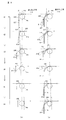
- States t1-t6 indicate changes in the state of the second connecting pieces 225, 226, 227 each time the drive gear 24a rotates by a step angle and the arm portion 2 moves by ⁇ d in the feeding direction.
- the state t1 shows a state in which the linear gear 22a of the second connecting piece 225 is engaged with the drive gear 24a.
- the drive gear 24a and the linear gear 22a of the second connecting piece 225 are engaged at the position P. And until the state t4, the state which the 2nd connection top 225 is sent out in the sending-out direction by the drive gear 24a is shown.
- the state t4 shows immediately after the drive gear 24a and the linear gear 22a of the second connecting piece 226 are engaged at the position P.
- States t5 and t6 show a state in which the second connecting piece 226 is sent out by the drive gear 24a.
- the angle ⁇ 41 that rotates at the moment when the second connecting piece 226 becomes horizontal as in the state t4 is large, the second connecting piece 226 rotates vigorously, and the second connecting piece 226 becomes the second support body. It may collide with the inner surface of 11b. As a result, there may be a problem that a collision sound is generated or the second connecting piece 226 is scraped off.
- the rotational angle ⁇ 42 at the moment when the linear gear 22a of the second connecting piece 226 is engaged with the drive gear 24a at the position P is the rotational angle when the guide rail 41 is not present. It is smaller than ⁇ 41. That is, at the moment when the linear gear 22a of the second connecting piece 226 is engaged with the drive gear 24a, the second connecting piece 226 does not rotate greatly. This is because the second connecting piece 226 is guided by the guide rail 41 and can be leveled to some extent immediately before the linear gear 22a of the second connecting piece 226 is engaged with the drive gear 24a (state t3).
- the presence of the guide rail 41 enables the guide rail 41 to intentionally disperse the rotation angle of 90 degrees required until the second connecting piece 226 changes from the retracted state to the horizontal state.
- the second connecting piece 226 rotates by ⁇ 21 in the state t2, ⁇ 31 in the state t3, and ⁇ 41 in the state t4, and is rotated by 90 degrees in total.
- the second connecting piece 226 rotates by ⁇ 12 in the state t1, ⁇ 22 in the state t2, ⁇ 32 in the state t3, ⁇ 42 in the state t4, ⁇ 52 in the state t5, and ⁇ 62 in the state t6.
- the guide rail 41 can be arranged along a previously designed track even when the arm unit 2 moves up and down.
- the track of the guide rail 41 can be designed based on the guide rail storage portion 48 and the bending angle of the guide rail 41.
- the 1st connection top row 21 and the 2nd connection top row 20 can be separated and stored in a storage part.
- the second connecting top row 20 can be guided to the injection unit 29 (feeding direction) along the guide rail 41 designed in advance.
- the guide rail 41 can disperse the rotation of the second connecting piece row 20 necessary until the guide rail 41 is sent out from the retracted state toward the front of the injection unit 29. Since the angle of rotation in unit time can be reduced, the second connecting piece 22 can be prevented from rotating vigorously. As a result, it is possible to prevent the second connecting piece 22 from colliding with the inner surface of the second support 11b, and consequently, it is possible to prevent the occurrence of a collision sound, the loss of the second connecting piece 22, and the like.
Abstract
The purpose of the present invention is to inhibit collisions between a first coupling-segment row and a second coupling-segment row in a robot arm mechanism provided with a direct-acting extensible/retractable joint. In this robot arm mechanism provided with a direct-acting extensible/retractable joint, the direct-acting extensible/retractable joint is provided with an arm part (2), and an ejection part (29) which supports the arm part (2). The arm part (2) is provided with: a first coupling-segment row (21) formed from a plurality of first coupling segments (23); and a second coupling-segment row (20) formed from a plurality of second coupling segments (22). The second coupling-segment row (20) is dispatched forwards from the ejection part (29) in conjunction with the first coupling-segment row (21), in a state of being joined to the first coupling-segment row (21). A flexible guide rail (41) for separating the first coupling-segment row (21) and the second coupling-segment row (20), and guiding the second coupling-segment row (20) to the ejection part (29), is provided to the rear of the ejection part (29), and between the first coupling-segment row (21) and the second coupling-segment row (20).
Description
本発明の実施形態はロボットアーム機構に関する。
The embodiment of the present invention relates to a robot arm mechanism.
従来より、多関節ロボットアーム機構が産業用ロボットなどさまざまな分野で用いられている。ロボットアーム機構には、例えば、直動伸縮関節が組み合わされて装備されている。直動伸縮関節を構成するアーム部は、例えば、第1連結コマ列と第2連結コマ列とで構成される。第1連結コマ列と第2連結コマ列とは、格納部に格納されている。直動関節を駆動するためにモータが順回転すると、格納部に格納されていた第1連結コマ列と第2連結コマ列とが接合され、柱状体となって送り出される。モータが逆回転するとアーム部は格納部に引き戻され、柱状体は第1連結コマ列と第2連結コマ列とに離反され格納部にそれぞれ格納される。このようなロボットアーム機構において、何も対策を講じなければ、格納部内で第1連結コマ列と第2連結コマ列とが衝突する可能性がある。
Conventionally, articulated robot arm mechanisms have been used in various fields such as industrial robots. The robot arm mechanism is equipped with, for example, a linear motion expansion joint. The arm part which comprises a linear motion expansion-contraction joint is comprised by the 1st connection top row | line | column and the 2nd connection top frame | sequence, for example. The first linked frame sequence and the second linked frame sequence are stored in the storage unit. When the motor rotates forward in order to drive the linear motion joint, the first connection frame row and the second connection frame row stored in the storage unit are joined and sent out as a columnar body. When the motor rotates in the reverse direction, the arm portion is pulled back to the storage portion, and the columnar body is separated into the first connection frame row and the second connection frame row and stored in the storage portion. In such a robot arm mechanism, if no measures are taken, there is a possibility that the first connected frame row and the second connected frame row collide in the storage unit.
目的は、直動伸縮関節を有するロボットアーム機構において、第1連結コマ列が第2連結コマ列に衝突するのを防ぐことにある。
The purpose is to prevent the first connected top row from colliding with the second connected top row in the robot arm mechanism having the linear motion telescopic joint.
本実施形態に係るロボットアーム機構は直動伸縮関節を有し、前記直動伸縮関節はアーム部と前記アーム部を支持する射出部とを有し、前記アーム部は、第1連結コマ列と第2連結コマ列とを有し、前記第1連結コマ列は、断面コ字形状、断面ロ字形状又は断面円弧形状を有する複数の第1連結コマから構成され、前記第2連結コマ列は、略平板形状を有する複数の第2連結コマから構成され、前記第2連結コマ列は前記第1連結コマ列に対し接合された状態で前記第1連結コマ列とともに前記射出部から前方に向かって送り出され、前記射出部の後方において、前記第1連結コマ列と前記第2連結コマ列との間には、前記第1連結コマ列と前記第2連結コマ列とを離間させるとともに前記第2連結コマ列を前記射出部に誘導するための可撓性を有するガイドレールが介在される。
The robot arm mechanism according to the present embodiment has a linear motion expansion / contraction joint, the linear motion expansion / contraction joint includes an arm portion and an ejection portion that supports the arm portion, and the arm portion includes a first connection top row and A second connection piece row, wherein the first connection piece row is composed of a plurality of first connection pieces having a U-shaped cross-section, a cross-sectional square shape, or a cross-sectional arc shape, A plurality of second connection pieces having a substantially flat plate shape, and the second connection piece row is forwardly connected to the first connection piece row together with the first connection piece row from the injection portion. The first connection frame row and the second connection frame row are separated from each other between the first connection frame row and the second connection frame row at the rear of the injection unit. Possible to guide two connected frame rows to the injection part Guide rail is interposed having sex.
以下、図面を参照しながら本実施形態に係るロボットアーム機構を説明する。以下の説明において、略同一の機能及び構成を有する構成要素については、同一符号を付し、重複説明は必要な場合にのみ行う。
Hereinafter, the robot arm mechanism according to the present embodiment will be described with reference to the drawings. In the following description, components having substantially the same function and configuration are denoted by the same reference numerals, and redundant description will be given only when necessary.
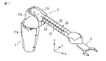
図1は、本実施形態に係るロボットアーム機構の外観斜視図である。図2、図3は図1のロボットアーム機構の内部構造を示している。ロボットアーム機構は、略円筒形状の基部1と基部1に接続するアーム部2とを有する。アーム部2の先端にはエンドエフェクタと呼ばれる手先効果器3が取り付けられる。図1では手先効果器3として対象物を把持可能なハンド部を図示している。手先効果器3としてはハンド部に限定されず、他のツール、またはカメラ、ディスプレイであってもよい。アーム部2の先端には任意の種類の手先効果器3に交換することができるアダプタが設けられていてもよい。
FIG. 1 is an external perspective view of the robot arm mechanism according to the present embodiment. 2 and 3 show the internal structure of the robot arm mechanism of FIG. The robot arm mechanism has a substantially cylindrical base 1 and an arm 2 connected to the base 1. A hand effector 3 called an end effector is attached to the tip of the arm unit 2. In FIG. 1, a hand unit capable of gripping an object is illustrated as the hand effector 3. The hand effector 3 is not limited to the hand unit, and may be another tool, a camera, or a display. An adapter that can be replaced with any kind of hand effector 3 may be provided at the tip of the arm portion 2.
アーム部2は、複数、ここでは6つの関節部J1,J2,J3,J4,J5,J6を有する。複数の関節部J1,J2,J3,J4,J5,J6は基部1から順番に配設される。一般的に、第1、第2、第3軸RA1,RA2,RA3は根元3軸と呼ばれ、第4、第5、第6軸RA4,RA5,RA6はハンド部3の姿勢を変化させる手首3軸と呼ばれる。根元3軸を構成する関節部J1,J2,J3の少なくとも一つは直動関節である。ここでは第3関節部J3が直動関節、特に伸縮距離の比較的長い関節部として構成される。第1関節部J1は台座面に対して例えば垂直に支持される第1回転軸RA1を中心としたねじり関節である。第2関節部J2は第1回転軸RA1に対して垂直に配置される第2回転軸RA2を中心とした曲げ関節である。第3関節部J3は、第2回転軸RA2に対して垂直に配置される第3軸(移動軸)RA3を中心として直線的に伸縮する関節である。第4関節部J4は、第3移動軸RA3に一致する第4回転軸RA4を中心としたねじり関節であり、第5関節部J5は第4回転軸RA4に対して直交する第5回転軸RA5を中心とした曲げ関節である。第6関節部J6は第4回転軸RA4に対して直交し、第5回転軸RA5に対して垂直に配置される第6回転軸RA6を中心とした曲げ関節である。
The arm portion 2 has a plurality of, here six joint portions J1, J2, J3, J4, J5 and J6. The plurality of joint portions J1, J2, J3, J4, J5, and J6 are sequentially arranged from the base portion 1. In general, the first, second, and third axes RA1, RA2, and RA3 are referred to as root three axes, and the fourth, fifth, and sixth axes RA4, RA5, and RA6 are wrists that change the posture of the hand unit 3. Called three axes. At least one of the joint portions J1, J2, and J3 constituting the base three axes is a linear motion joint. Here, the third joint portion J3 is configured as a linear motion joint, particularly a joint portion having a relatively long expansion / contraction distance. The first joint portion J1 is a torsional joint centered on a first rotation axis RA1 that is supported, for example, perpendicularly to the pedestal surface. The second joint portion J2 is a bending joint centered on the second rotation axis RA2 arranged perpendicular to the first rotation axis RA1. The third joint portion J3 is a joint that linearly expands and contracts around a third axis (moving axis) RA3 arranged perpendicular to the second rotation axis RA2. The fourth joint portion J4 is a torsion joint centered on the fourth rotation axis RA4 that coincides with the third movement axis RA3, and the fifth joint portion J5 is a fifth rotation axis RA5 orthogonal to the fourth rotation axis RA4. It is a bending joint centered around. The sixth joint portion J6 is a bending joint centered on the sixth rotation axis RA6 that is perpendicular to the fourth rotation axis RA4 and perpendicular to the fifth rotation axis RA5.
第1関節部J1のねじり回転によりアーム部2がハンド部3とともに旋回する。第2関節部J2の曲げ回転によりアーム部2がハンド部3とともに第2関節部J2の第2回転軸RA2を中心に起伏動をする。基部1を成すアーム支持体(第1支持体)11aは、第1関節部J1の回転軸RA1を中心に形成される円筒形状の中空構造を有する。第1関節部J1は図示しない固定台に取り付けられる。第1関節部J1が回転するとき、第1支持体11aはアーム部2の旋回とともに軸回転する。なお、第1支持体11aが接地面に固定されていてもよい。その場合、第1支持体11aとは独立してアーム部2が旋回する構造に設けられる。第1支持体11aの上部には第2支持部11bが接続される。
The arm part 2 turns together with the hand part 3 by the torsional rotation of the first joint part J1. By bending and rotating the second joint portion J2, the arm portion 2 moves up and down around the second rotation axis RA2 of the second joint portion J2 together with the hand portion 3. The arm support body (first support body) 11a forming the base portion 1 has a cylindrical hollow structure formed around the rotation axis RA1 of the first joint portion J1. The first joint portion J1 is attached to a fixed base (not shown). When the first joint portion J <b> 1 rotates, the first support 11 a rotates along with the turning of the arm portion 2. The first support 11a may be fixed to the ground plane. In that case, the arm part 2 is provided in a structure that turns independently of the first support 11a. A second support part 11b is connected to the upper part of the first support 11a.
第2支持部11bは第1支持部11aに連続する中空構造を有する。第2支持部11bの一端は第1関節部J1の回転部に取り付けられる。第2支持部11bの他端は開放され、第3支持部11cが第2関節部J2の回転軸RA2において回動自在に嵌め込まれる。第3支持部11cは第1支持部11a及び第2支持部に連通する鱗状の中空構造を有する。第3支持部11cは、第2関節部J2の曲げ回転に伴ってその後部が第2支持部11bに収容され、また送出される。アーム部2の直動関節部を構成する第3関節部J3の後部はその収縮により第1支持部11aと第2支持部11bの連続する中空構造の内部に格納される。当該中空構造の内部を、格納部とも呼ぶ。
The second support portion 11b has a hollow structure that is continuous with the first support portion 11a. One end of the second support portion 11b is attached to the rotating portion of the first joint portion J1. The other end of the second support portion 11b is opened, and the third support portion 11c is rotatably fitted on the rotation axis RA2 of the second joint portion J2. The 3rd support part 11c has a scale-like hollow structure connected to the 1st support part 11a and the 2nd support part. The third support portion 11c is accommodated in the second support portion 11b and sent out as the second joint portion J2 is bent and rotated. The rear portion of the third joint portion J3 that constitutes the linear motion joint portion of the arm portion 2 is housed in the hollow structure in which the first support portion 11a and the second support portion 11b are continuous by contraction thereof. The inside of the hollow structure is also called a storage part.
第1関節部J1は円環形状の固定部と回転部とからなり、固定部において台座に固定される。回転部には第1支持部11aと第2支持部11bとが取り付けられる。第1関節部J1が回転するとき、第1、第2、第3支持体11a、11b、11cが第1回転軸RA1を中心としてアーム部2とハンド部3と共に旋回する。
The first joint portion J1 includes an annular fixed portion and a rotating portion, and is fixed to the pedestal at the fixed portion. A first support portion 11a and a second support portion 11b are attached to the rotating portion. When the first joint portion J1 rotates, the first, second, and third supports 11a, 11b, and 11c rotate together with the arm portion 2 and the hand portion 3 about the first rotation axis RA1.
第3支持部11cはその後端下部において第2支持部11bの開放端下部に対して回転軸RA2を中心として回動自在に嵌め込まれる。それにより回転軸RA2を中心とした曲げ関節部としての第2関節部J2が構成される。第2関節部J2が回動すると、アーム部2がハンド部3とともに第2関節部J2の回転軸RA2を中心に垂直方向に回動、つまり起伏動作をする。第2関節部J2の回転軸RA2は、ねじり関節部としての第1関節部J1の第1回転軸RA1に垂直に設けられる。
The third support portion 11c is fitted to the lower end portion of the second support portion 11b so as to be rotatable about the rotation axis RA2 at the lower end portion of the second support portion 11b. As a result, a second joint portion J2 is formed as a bending joint portion around the rotation axis RA2. When the second joint portion J2 rotates, the arm portion 2 rotates in a vertical direction around the rotation axis RA2 of the second joint portion J2 together with the hand portion 3, that is, performs a undulation operation. The rotation axis RA2 of the second joint portion J2 is provided perpendicular to the first rotation axis RA1 of the first joint portion J1 as a torsion joint portion.
上記の通り関節部としての第3関節部J3はアーム部2の主要構成物を構成する。アーム部2の先端に上述のハンド部3が設けられる。ハンド部3は、図1に示すようにアーム部2の先に装備されている。ハンド部3は、第1、第2、第3関節部J1.J2.J3により任意位置に移動され、第4、第5、第6関節部J4、J5、J6により任意姿勢に配置される。ハンド部3は、開閉される2つの指部16a、16bを有している。第4関節部J4は、アーム部2の伸縮方向に沿ったアーム部2の中心軸、つまり第3関節部J3の移動軸RA3に典型的には一致する回転軸RA4を有するねじり関節である。第4関節部J4が回転すると、第4関節部J4から先端にかけてハンド部3が回転軸RA4を中心に回転する。
As described above, the third joint portion J3 as the joint portion constitutes a main component of the arm portion 2. The hand portion 3 described above is provided at the tip of the arm portion 2. As shown in FIG. 1, the hand unit 3 is provided at the tip of the arm unit 2. The hand portion 3 includes first, second, and third joint portions J1. J2. It is moved to an arbitrary position by J3, and is arranged in an arbitrary posture by the fourth, fifth, and sixth joint portions J4, J5, and J6. The hand portion 3 has two finger portions 16a and 16b that are opened and closed. The fourth joint portion J4 is a torsional joint having a rotation axis RA4 that typically coincides with the central axis of the arm portion 2 along the extending and contracting direction of the arm portion 2, that is, the movement axis RA3 of the third joint portion J3. When the fourth joint portion J4 rotates, the hand portion 3 rotates about the rotation axis RA4 from the fourth joint portion J4 to the tip.
第5関節部J5は、第4関節部J4の移動軸RA4に対して直交する回転軸RA5を有する曲げ関節部である。第5関節部が回転すると、第5関節部J5から先端にかけてハンド部16とともに上下に回動する。第6関節部J6は、第4関節部J4の回転軸RA4に直交し、第5関節部J5の回転軸RA5に垂直な回転軸RA6を有する曲げ関節である。第6関節部J6が回転するとハンド16が左右に旋回する。
The fifth joint J5 is a bending joint having a rotation axis RA5 orthogonal to the movement axis RA4 of the fourth joint J4. When the fifth joint portion rotates, it rotates up and down together with the hand portion 16 from the fifth joint portion J5 to the tip. The sixth joint portion J6 is a bending joint having a rotation axis RA6 perpendicular to the rotation axis RA4 of the fourth joint portion J4 and perpendicular to the rotation axis RA5 of the fifth joint portion J5. When the sixth joint J6 rotates, the hand 16 turns left and right.
第1乃至第6関節部J1-J6の回転、曲げ、伸縮によりハンド部3の2指ハンド16を任意の位置・姿勢に配置することが可能である。特に第3関節部J3の直動伸縮距離の長さは、基部1の近接位置から遠隔位置までの広範囲の対象にハンド部3で作用することを可能にする。
It is possible to place the two-finger hand 16 of the hand part 3 in an arbitrary position and posture by rotating, bending, and extending / contracting the first to sixth joint parts J1-J6. In particular, the length of the linear motion expansion / contraction distance of the third joint portion J3 enables the hand portion 3 to act on a wide range of objects from the proximity position of the base 1 to the remote position.
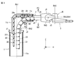
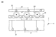
第3関節部J3はそれを構成する直動伸縮アーム機構により実現される直動伸縮距離の長さが特徴的である。直動伸縮距離の長さは、図2、図3に示す構造により達成される。直動伸縮アーム機構は第1連結コマ列21と第2連結コマ列20とを有する。アーム部2が水平に配置される基準姿勢では、第1連結コマ列21は第2連結コマ列20の下部に位置し、第2連結コマ列20は第1連結コマ列21の上部に位置する。
The third joint portion J3 is characterized by the length of the linear motion expansion / contraction distance realized by the linear motion expansion / contraction arm mechanism constituting the third joint portion J3. The length of the linear expansion / contraction distance is achieved by the structure shown in FIGS. The direct acting telescopic arm mechanism has a first connecting frame row 21 and a second connecting frame row 20. In the reference posture in which the arm unit 2 is horizontally disposed, the first connection frame row 21 is positioned below the second connection frame row 20, and the second connection frame row 20 is positioned above the first connection frame row 21. .
第1連結コマ列21は、同一の断面コ字形状を有し、ピンにより背面箇所において列状に連結される複数の第1連結コマ23からなる。第1連結コマ23の断面形状及びピンによる連結位置により第1連結コマ列21はその背面方向BDに屈曲可能であるが逆に表面方向FDには屈曲不可な性質を備える。したがって、第1連結コマ23の断面形状は、コ字形状だけでなく、断面ロ字形状、円弧形状等であってもよい。
The first connecting piece row 21 has the same U-shaped cross section, and is composed of a plurality of first connecting pieces 23 connected in a row at the back portion by pins. Depending on the cross-sectional shape of the first connecting piece 23 and the connecting position by the pins, the first connecting piece row 21 can be bent in the back surface direction BD, but conversely, it cannot be bent in the surface direction FD. Accordingly, the cross-sectional shape of the first connecting piece 23 is not limited to the U-shape, but may be a cross-sectional shape, an arc shape, or the like.
第2連結コマ列20は、第1連結コマ23と略等価な幅を有する略平板形状を有し、背面方向BDと表面方向FDとともに屈曲可能な状態でピンにより列状に連結される複数の第2連結コマ22からなる。第1連結コマ列21は第2連結コマ列20と先端部おいて結合コマ26により結合される。結合コマ26は、第1連結コマ23と第2連結コマ22とが一体的になった形状を有している。図2に示すように第2連結コマ22の内側(背面側)には個々にリニアギア22aが形成されている。リニアギア22aは第2連結コマ22が直線状になったときに連結され、連続的なリニアギア(ラック)を構成する。第1連結コマ23の正面側は、第2連結コマ22の背面側と対向する。第1連結コマ23の背面側および第2連結コマ22の正面側は、基部1、第2支持体11bまたは第3支持体11cの内面に対向する。
The second connecting piece row 20 has a substantially flat plate shape having a width substantially equivalent to that of the first connecting piece 23, and is connected in a row with pins in a state where it can be bent together with the back direction BD and the surface direction FD. It consists of a second connecting piece 22. The first connection frame row 21 is connected to the second connection frame row 20 by a connection piece 26 at the tip. The connecting piece 26 has a shape in which the first connecting piece 23 and the second connecting piece 22 are integrated. As shown in FIG. 2, linear gears 22 a are individually formed on the inner side (back side) of the second connecting piece 22. The linear gear 22a is connected when the second connecting piece 22 becomes linear, and forms a continuous linear gear (rack). The front side of the first connecting piece 23 faces the back side of the second connecting piece 22. The back side of the first connecting piece 23 and the front side of the second connecting piece 22 are opposed to the inner surface of the base 1, the second support 11b, or the third support 11c.
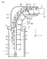
図3は、図1のロボットアーム機構の内部構造を断面方向から見た図である。
図3に示すように、第2連結コマ22は射出部29でローラ291とドライブギア24aとの間に挟まれる。それにより、リニアギア22aはドライブギア24aに噛み合わされる。アーム伸長時、モータM1が駆動し、ドライブギア24aが順回転することにより第2連結コマ列20は第1連結コマ列21とともに射出部29から前方に向かって送り出される。その際、第1連結コマ列21と第2連結コマ列20とは射出部29で挟まれ、相互に押圧され、接合される。このとき、第1連結コマ23の表面側が第2連結コマ22の背面側と接合される。接合された第1連結コマ列21と第2連結コマ列20とは射出部29により支持されることにより接合状態が保持される。第1連結コマ列21と第2連結コマ列20との接合状態が保持されたとき、第1連結コマ列21と第2連結コマ列20の屈曲は制限され、それにより第1連結コマ列21と第2連結コマ列20とにより一定の剛性を備えた柱状体が構成される。結合コマ26が始端となって、接合された柱状体(第1連結コマ列21と第2連結コマ列20と)が第3移動軸RA3に沿って直線的に送り出される。射出部29は、角筒形状を有する。中空部分の幅の大きさは、柱状体の幅に略一致する。その側面には、複数のローラ291が回転自在に設けられ、柱状体を側方から支持する。射出部29は、第2支持体11cまたは第2支持体11bに固定される。そのため、射出部29は、第1回転軸RA1を中心としてアーム部2とハンド部3と共に旋回する。また、射出部29は、第2回転軸RA2を中心にアーム部2とハンド部3と共に垂直方向に回動、つまり起伏動作をする。 FIG. 3 is a view of the internal structure of the robot arm mechanism of FIG. 1 as viewed from the cross-sectional direction.
As shown in FIG. 3, thesecond connection piece 22 is sandwiched between the roller 291 and the drive gear 24 a by the injection unit 29. Thereby, the linear gear 22a is meshed with the drive gear 24a. When the arm is extended, the motor M1 is driven and the drive gear 24a rotates forward, so that the second connecting piece row 20 is sent forward from the injection unit 29 together with the first connecting piece row 21. In that case, the 1st connection top row | line | column 21 and the 2nd connection top row | line | column 20 are pinched | interposed by the injection part 29, and are mutually pressed and joined. At this time, the surface side of the first connection piece 23 is joined to the back side of the second connection piece 22. The joined first connected frame row 21 and the second connected piece row 20 are supported by the injection unit 29, so that the joined state is maintained. When the joining state of the first connection top row 21 and the second connection top row 20 is maintained, the bending of the first connection top row 21 and the second connection top row 20 is limited, thereby the first connection top row 21. And the second connecting piece row 20 constitute a columnar body having a certain rigidity. The joined pieces 26 (starting ends) are joined, and the joined columnar bodies (the first connecting piece row 21 and the second connecting piece row 20) are sent out linearly along the third movement axis RA3. The injection part 29 has a rectangular tube shape. The size of the width of the hollow portion substantially matches the width of the columnar body. A plurality of rollers 291 are rotatably provided on the side surface, and support the columnar body from the side. The injection unit 29 is fixed to the second support 11c or the second support 11b. Therefore, the injection unit 29 turns together with the arm unit 2 and the hand unit 3 around the first rotation axis RA1. In addition, the injection unit 29 rotates in the vertical direction together with the arm unit 2 and the hand unit 3 around the second rotation axis RA2, that is, performs a hoisting operation.
図3に示すように、第2連結コマ22は射出部29でローラ291とドライブギア24aとの間に挟まれる。それにより、リニアギア22aはドライブギア24aに噛み合わされる。アーム伸長時、モータM1が駆動し、ドライブギア24aが順回転することにより第2連結コマ列20は第1連結コマ列21とともに射出部29から前方に向かって送り出される。その際、第1連結コマ列21と第2連結コマ列20とは射出部29で挟まれ、相互に押圧され、接合される。このとき、第1連結コマ23の表面側が第2連結コマ22の背面側と接合される。接合された第1連結コマ列21と第2連結コマ列20とは射出部29により支持されることにより接合状態が保持される。第1連結コマ列21と第2連結コマ列20との接合状態が保持されたとき、第1連結コマ列21と第2連結コマ列20の屈曲は制限され、それにより第1連結コマ列21と第2連結コマ列20とにより一定の剛性を備えた柱状体が構成される。結合コマ26が始端となって、接合された柱状体(第1連結コマ列21と第2連結コマ列20と)が第3移動軸RA3に沿って直線的に送り出される。射出部29は、角筒形状を有する。中空部分の幅の大きさは、柱状体の幅に略一致する。その側面には、複数のローラ291が回転自在に設けられ、柱状体を側方から支持する。射出部29は、第2支持体11cまたは第2支持体11bに固定される。そのため、射出部29は、第1回転軸RA1を中心としてアーム部2とハンド部3と共に旋回する。また、射出部29は、第2回転軸RA2を中心にアーム部2とハンド部3と共に垂直方向に回動、つまり起伏動作をする。 FIG. 3 is a view of the internal structure of the robot arm mechanism of FIG. 1 as viewed from the cross-sectional direction.
As shown in FIG. 3, the
アーム収縮時、モータM1が駆動し、ドライブギア24aが逆回転することにより第2連結コマ列20と第1連結コマ列21とは射出部29で接合状態が解除され、互いに離反される。離反された第2連結コマ列20と第1連結コマ列21とはそれぞれ屈曲可能な状態になり、第1回転軸RA1に沿う方向に屈曲され、格納部に格納される。
When the arm contracts, the motor M1 is driven and the drive gear 24a rotates in the reverse direction, whereby the second connecting piece row 20 and the first connecting piece row 21 are released from the joined state by the injection portion 29 and separated from each other. The separated second connection top row 20 and first connection top row 21 are in a bendable state, bent in the direction along the first rotation axis RA1, and stored in the storage unit.
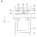
図4は、本実施形態に係るロボットアーム機構の格納構造を示す図である。ガイドレール41は、ピンにより列状に連結された複数のレールコマ43により構成される。図4に示すように、ガイドレール41の一端は、先頭のレールコマ43のピンホール431、432を利用して射出部29の後端部分に取り付けられる。ガイドレール41の他端には、最後尾のレールコマ43のピンホール433を利用してバネ50の一端が固定される。バネ50の他端は基部1(第1支持体11a)の底面に固定される。バネ50は基部1の軸方向に伸縮する。第1支持体11aには、ガイドレール格納部48が固定される。ガイドレール格納部48は、基部1の内面に固定される。ガイドレール格納部48は、一対のスライドレールで構成されている。レールコマ43の両端がそれぞれスライドレールに沿ってスライドして格納される。ガイドレール格納部48は、第2支持体11bに延長されてもよい。
FIG. 4 is a view showing a storage structure of the robot arm mechanism according to the present embodiment. The guide rail 41 is composed of a plurality of rail pieces 43 connected in a row by pins. As shown in FIG. 4, one end of the guide rail 41 is attached to the rear end portion of the injection portion 29 using the pinholes 431 and 432 of the leading rail piece 43. One end of the spring 50 is fixed to the other end of the guide rail 41 using a pinhole 433 of the rearmost rail piece 43. The other end of the spring 50 is fixed to the bottom surface of the base 1 (first support 11a). The spring 50 expands and contracts in the axial direction of the base 1. A guide rail storage 48 is fixed to the first support 11a. The guide rail storage 48 is fixed to the inner surface of the base 1. The guide rail storage 48 is composed of a pair of slide rails. Both ends of the rail piece 43 are slid along the slide rail and stored. The guide rail storage part 48 may be extended to the second support 11b.
次に、ガイドレール41を構成する複数のレールコマ43について、図5、6、7を参照して説明する。
Next, a plurality of rail pieces 43 constituting the guide rail 41 will be described with reference to FIGS.
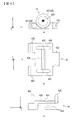
図5は、本実施形態に係るロボットアーム機構のレールコマ43の構造を示す図である。図5では、レールコマ43を直交3軸方向からそれぞれ見た図を示している。図5(a),(b),(c)は、それぞれレールコマ43を側方(+X方向)、上方(+Z方向)、後方(+Y方向)から見た図である。
FIG. 5 is a view showing the structure of the rail piece 43 of the robot arm mechanism according to the present embodiment. FIG. 5 shows a view of the rail piece 43 as seen from three orthogonal directions. FIGS. 5A, 5B, and 5C are views of the rail piece 43 viewed from the side (+ X direction), the upper side (+ Z direction), and the rear side (+ Y direction), respectively.
図6は、図4に対応し、ガイドレール41と第1連結コマ列21と第2連結コマ列20との間の実際の位置関係を断面方向から見た図である。
図7は、図4に対応し、ガイドレール41と第1連結コマ列21と第2連結コマ列20との間の実際の位置関係を送り出し方向から見た図である。 FIG. 6 corresponds to FIG. 4, and is a view of the actual positional relationship among theguide rail 41, the first connecting piece row 21, and the second connecting piece row 20 as seen from the cross-sectional direction.
FIG. 7 corresponds to FIG. 4, and is a view of an actual positional relationship among theguide rail 41, the first connecting piece row 21, and the second connecting piece row 20 as viewed from the feeding direction.
図7は、図4に対応し、ガイドレール41と第1連結コマ列21と第2連結コマ列20との間の実際の位置関係を送り出し方向から見た図である。 FIG. 6 corresponds to FIG. 4, and is a view of the actual positional relationship among the
FIG. 7 corresponds to FIG. 4, and is a view of an actual positional relationship among the
図5に示すように、レールコマ43の先端部分は凹形状を有し、その両側にはレールコマ43の後端部分と連結するためのピンが挿入されるピンホール431、432が形成されている。ピンホール431、432の軸方向はレールコマ43の幅方向に平行である。ピンホール431は、ピンホール432と同じ軸長を有する。ピンホール431の軸長にピンホール432の軸長を加算した長さはレールコマ43の幅よりも短い。レールコマ43の後端部分は凸形状を有し、レールコマ43の先端部分と連結するためのピンが挿入されるピンホール433が形成されている。ピンホール433の軸方向はレールコマ43の幅方向に平行である。ピンホール433の軸長は、レールコマ43の幅よりも短い。ピンホール431,432、433各々の軸長を合算した長さはレールコマ43の幅と略一致する。しかしながら、ピンホール431,432、433各々の軸長を合算した長さは、レールコマ43の幅以下であればよい。隣接する一方のレールコマ43の後端に他方のレールコマの先端を嵌めたとき、ピンホール431、432、433は直線上の単一のピンホールを構成する。この単一のピンホールに単一ピンが挿入されることにより隣接するレールコマ43は連結される。
As shown in FIG. 5, the front end portion of the rail piece 43 has a concave shape, and pin holes 431 and 432 into which pins for connecting to the rear end portion of the rail piece 43 are inserted are formed on both sides thereof. The axial directions of the pinholes 431 and 432 are parallel to the width direction of the rail piece 43. The pinhole 431 has the same axial length as the pinhole 432. The length obtained by adding the axial length of the pinhole 432 to the axial length of the pinhole 431 is shorter than the width of the rail piece 43. The rear end portion of the rail piece 43 has a convex shape, and a pin hole 433 into which a pin for connecting to the front end portion of the rail piece 43 is inserted is formed. The axial direction of the pinhole 433 is parallel to the width direction of the rail piece 43. The axial length of the pinhole 433 is shorter than the width of the rail piece 43. The total length of the axial lengths of the pinholes 431, 432, and 433 substantially matches the width of the rail piece 43. However, the total length of the axial lengths of the pinholes 431, 432, 433 may be equal to or less than the width of the rail piece 43. When the tip of the other rail piece is fitted to the rear end of one adjacent rail piece 43, the pinholes 431, 432, and 433 constitute a single straight pinhole. Adjacent rail pieces 43 are connected by inserting a single pin into this single pinhole.
図6に示すように、レールコマ43の先端のピンホール431,432から後端のピンホール433までの長さL3は、第2連結コマ22の先端のピンホールから後端のピンホールまでの長さL2よりも短い。図4に示すように、第2回転軸RA2を中心として、第1連結コマ列21、第2連結コマ列20およびガイドレール41が回転される。そのとき、ガイドレール41は第2連結コマ列20よりも内側にある。そのため、レールコマ43の長さL3が第2連結コマ22の長さL2よりも短いことで、ガイドレール41の軌道を第2連結コマ列20の軌道よりもなめらかにすることができる。それによりガイドレール41は、第2連結コマ列20を射出部20にスムーズに誘導することができる。なお、第1連結コマ23の先端のピンホールから後端のピンホールまでの長さL1は、第2連結コマ22の先端のピンホールから後端のピンホールまでの長さL2と略同一の長さを有する。
As shown in FIG. 6, the length L3 from the pinholes 431 and 432 at the front end of the rail piece 43 to the pinhole 433 at the rear end is the length from the pinhole at the front end of the second connection piece 22 to the pinhole at the rear end. Shorter than L2. As shown in FIG. 4, the first connecting piece row 21, the second connecting piece row 20, and the guide rail 41 are rotated around the second rotation axis RA2. At that time, the guide rail 41 is on the inner side of the second connecting frame row 20. Therefore, since the length L3 of the rail piece 43 is shorter than the length L2 of the second connection piece 22, the track of the guide rail 41 can be made smoother than the track of the second connection piece row 20. As a result, the guide rail 41 can smoothly guide the second connecting frame row 20 to the injection unit 20. Note that the length L1 from the tip pinhole to the rear end pinhole of the first connection piece 23 is substantially the same as the length L2 from the tip pinhole to the rear end pinhole of the second connection piece 22. Have a length.
図7に示すように、レールコマ43の幅W3は、第1連結コマ23の幅W1及び第2連結コマ22の幅W2よりも長い。第1連結コマ23の幅W1は、第2連結コマ22の幅W2と同一の長さを有する。例えば、レールコマ43の幅W3は、第1連結コマ23の幅W1の1.05倍乃至1.5倍の長さを有する。それにより、例えば、第1連結コマ23及び第2連結コマ22が、何らかの理由で幅方向にずれた場合であっても、レールコマ43により、第1連結コマ23と第2連結コマとの干渉を防ぐことができる。
As shown in FIG. 7, the width W3 of the rail piece 43 is longer than the width W1 of the first connection piece 23 and the width W2 of the second connection piece 22. The width W1 of the first connecting piece 23 has the same length as the width W2 of the second connecting piece 22. For example, the width W3 of the rail piece 43 has a length that is 1.05 to 1.5 times the width W1 of the first connection piece 23. Thereby, for example, even if the first connecting piece 23 and the second connecting piece 22 are displaced in the width direction for some reason, the rail piece 43 causes interference between the first connecting piece 23 and the second connecting piece. Can be prevented.
図5に示すように、レールコマ43の長さ方向の中点付近の表面には、シャフトホール434が形成されている。シャフトホール434の軸方向は、レールコマ43の幅方向に平行である。シャフトホール434の軸方向の中点はレールコマ43の幅方向の中点に一致する。シャフトホール434は、第2連結コマ22の幅W2よりも短く、好適には、図7に示すように、第2連結コマ22の背面に設けられる2つのロック部221の一方の外側面から他方の外側面までの長さ程度の軸長を有する。シャフトホール434には、シャフトホール434よりも長いシャフト435が挿入される。シャフト435の両端には、ホイール437、438がそれぞれ固定されている。ホイール437は、その表面が弾性体、例えばゴムで覆われている。それにより、ホイール437,438が第2連結コマ22に接触することによる、第2連結コマ22の欠損を防止することができる。ホイール437は、第2連結コマ22の側面から第2連結コマ22の背面に設けられるロック部221の外側面までよりも短い幅を有する。また、ホイール437は、第2連結コマ22の背面からロック部221の下端までの距離よりも長い半径を有する。ホイール438は、ホイール437と同一形状を有する。
As shown in FIG. 5, a shaft hole 434 is formed on the surface of the rail piece 43 near the midpoint in the length direction. The axial direction of the shaft hole 434 is parallel to the width direction of the rail piece 43. The midpoint of the shaft hole 434 in the axial direction coincides with the midpoint of the rail piece 43 in the width direction. The shaft hole 434 is shorter than the width W <b> 2 of the second connection piece 22, and preferably, as shown in FIG. 7, the one from the outer surface of the two lock portions 221 provided on the back surface of the second connection piece 22 to the other. It has an axial length on the order of the length to the outer surface. A shaft 435 longer than the shaft hole 434 is inserted into the shaft hole 434. Wheels 437 and 438 are fixed to both ends of the shaft 435, respectively. The surface of the wheel 437 is covered with an elastic body such as rubber. Thereby, the loss | disconnection of the 2nd connection top 22 by the wheels 437 and 438 contacting the 2nd connection top 22 can be prevented. The wheel 437 has a shorter width than the side surface of the second connection piece 22 to the outer side surface of the lock portion 221 provided on the back surface of the second connection piece 22. The wheel 437 has a radius longer than the distance from the back surface of the second connection piece 22 to the lower end of the lock portion 221. The wheel 438 has the same shape as the wheel 437.
シャフトホール434の両端からレールコマ43の側面までの間には窪みが形成されている。シャフトホール434のホール中心から窪みの底面までの深さは、ホイール437,438の半径よりも少し深い。また、シャフトホール434のホール中心から窪みの長さ方向の端までの長さは、ホイール437,438の半径よりも少し長い。それにより、シャフト435の両端に固定されたホイール437、438は、レールコマ43に干渉せずに回転することができる。例えば、レールコマ43を側方から見たときの窪みは円弧形状を有する。
A recess is formed between both ends of the shaft hole 434 and the side surface of the rail piece 43. The depth from the hole center of the shaft hole 434 to the bottom surface of the recess is slightly deeper than the radii of the wheels 437 and 438. Further, the length from the hole center of the shaft hole 434 to the end in the length direction of the recess is slightly longer than the radius of the wheels 437 and 438. Thereby, the wheels 437 and 438 fixed to both ends of the shaft 435 can rotate without interfering with the rail piece 43. For example, the recess when the rail piece 43 is viewed from the side has an arc shape.
レールコマ43の表面から第2連結コマ22に向かって突出する突出長は、ホイール437,438の半径に略同一である。レールコマ43が第2連結コマ22に接触するとき、レールコマ43のコマ437,438は、第2連結コマ22の背面に接触し、ロック部221に接触しない。
The protruding length that protrudes from the surface of the rail piece 43 toward the second connecting piece 22 is substantially the same as the radius of the wheels 437 and 438. When the rail piece 43 comes into contact with the second connection piece 22, the pieces 437 and 438 of the rail piece 43 come into contact with the back surface of the second connection piece 22 and do not come into contact with the lock portion 221.
次に、ガイドレール41の構造について説明する。
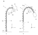
図8は、本実施形態に係るロボットアーム機構のガイドレール41の構造を示す図である。図8(a)は、アーム部2が水平に配置された姿勢(以下、水平姿勢と称す。)時のガイドレール41を示している。図8(b)は、アーム部2が図8(a)の姿勢から下方に所定角度伏せられた姿勢(以下、下方姿勢と称す。)時のガイドレール41を示している。 Next, the structure of theguide rail 41 will be described.
FIG. 8 is a view showing the structure of theguide rail 41 of the robot arm mechanism according to the present embodiment. FIG. 8A shows the guide rail 41 in a posture in which the arm portion 2 is disposed horizontally (hereinafter referred to as a horizontal posture). FIG. 8B shows the guide rail 41 when the arm portion 2 is in a posture (hereinafter referred to as a downward posture) in which the arm portion 2 is inclined downward by a predetermined angle from the posture of FIG.
図8は、本実施形態に係るロボットアーム機構のガイドレール41の構造を示す図である。図8(a)は、アーム部2が水平に配置された姿勢(以下、水平姿勢と称す。)時のガイドレール41を示している。図8(b)は、アーム部2が図8(a)の姿勢から下方に所定角度伏せられた姿勢(以下、下方姿勢と称す。)時のガイドレール41を示している。 Next, the structure of the
FIG. 8 is a view showing the structure of the
図8に示すように、アーム部2が水平姿勢から下方姿勢に変化すると、射出部29は第2回転軸RA2を中心に所定角度回転する。それに伴って、ガイドレール41は射出部2に引っ張られる。射出部29によりガイドレール41に引張力が働くと、バネ50が伸ばされ、ガイドレール格納部48からガイドレール41が引き出される。一方、アーム部2が下方姿勢から水平姿勢に戻るとき、ガイドレール格納部48から引き出されたガイドレール41がガイドレール格納部48に格納される。このとき、バネ50によりガイドレール41に付勢力が働く、それによりガイドレール41をスムーズにガイドレール格納部48に格納することができる。なお、ガイドレール41の後端がフリーであってもよい。このとき、上述のようなバネ50の効果は得られない。
As shown in FIG. 8, when the arm portion 2 changes from the horizontal posture to the downward posture, the injection portion 29 rotates by a predetermined angle about the second rotation axis RA2. Accordingly, the guide rail 41 is pulled by the injection unit 2. When a tensile force is applied to the guide rail 41 by the injection portion 29, the spring 50 is extended and the guide rail 41 is pulled out from the guide rail storage portion 48. On the other hand, when the arm unit 2 returns from the downward posture to the horizontal posture, the guide rail 41 pulled out from the guide rail storage portion 48 is stored in the guide rail storage portion 48. At this time, a biasing force is applied to the guide rail 41 by the spring 50, whereby the guide rail 41 can be smoothly stored in the guide rail storage portion 48. Note that the rear end of the guide rail 41 may be free. At this time, the effect of the spring 50 as described above cannot be obtained.
ガイドレール41は、可撓性を有する。具体的には、ガイドレール41は表面方向に屈曲不可であって、背面方向に屈曲する構造を有する。このとき、背面方向に屈曲する屈曲角度θmaxは制限されている。連結部分の屈曲角は、2つのレールコマ43を連結するピンにより制限される。なお、連結部分の屈曲角は、連結部分のコマ形状により制限されてもよい。
The guide rail 41 has flexibility. Specifically, the guide rail 41 has a structure that cannot be bent in the surface direction and bends in the back direction. At this time, the bending angle θmax that bends in the back direction is limited. The bending angle of the connecting portion is limited by a pin that connects the two rail pieces 43. Note that the bending angle of the connecting portion may be limited by the frame shape of the connecting portion.
ガイドレール格納部48は、基部1の軸方向に沿ってガイドレール41を格納する機能に加えて、ガイドレール41の屈曲を許可する範囲を限定する機能を有する。基部1に格納されているガイドレール41を屈曲不可にすることで、ガイドレール41が第1連結コマ列21に接触するのを回避することができる。例えば、図8に示すように、水平姿勢から下方姿勢に姿勢が変化したときを想定する。このとき射出部29によりガイドレール41が引っ張られる。基部1内のガイドレール41が引っ張られる方向は、基部1の軸方向に平行ではなく、第1連結コマ21側に少し傾いた方向に引っ張られる。ガイドレール41の全部分が屈曲できる場合、ガイドレール41が第1連結コマ列21側に傾いてしまう可能性がある。それによりガイドレール41が第1連結コマ列21に接触してしまい、第1連結コマ列21のスムーズな送り出しを妨害してしまう可能性がある。基部1に格納されているガイドレール41がガイドレール格納部48に格納されている場合、ガイドレール41がどのように引っ張られても、ガイドレール41はガイドレール格納部48に格納されていて傾かない。そのため、第1連結コマ列21及び第2連結コマ列20に接触することはない。
The guide rail storage 48 has a function of limiting the range in which the guide rail 41 is allowed to be bent, in addition to the function of storing the guide rail 41 along the axial direction of the base 1. By making the guide rails 41 stored in the base 1 unbendable, it is possible to avoid the guide rails 41 coming into contact with the first connection top row 21. For example, as shown in FIG. 8, it is assumed that the posture changes from a horizontal posture to a downward posture. At this time, the guide rail 41 is pulled by the injection portion 29. The direction in which the guide rail 41 in the base 1 is pulled is not parallel to the axial direction of the base 1 but is pulled in a direction slightly inclined toward the first connecting piece 21 side. When the entire portion of the guide rail 41 can be bent, the guide rail 41 may be inclined toward the first connecting piece row 21 side. As a result, the guide rail 41 may come into contact with the first connection frame row 21, which may hinder smooth feeding of the first connection frame row 21. When the guide rail 41 stored in the base 1 is stored in the guide rail storage portion 48, the guide rail 41 is stored in the guide rail storage portion 48 and tilted no matter how the guide rail 41 is pulled. No. Therefore, the first connected frame row 21 and the second connected frame row 20 do not come into contact with each other.
一方、ガイドレール格納部48の先端から射出部29までの間は、ガイドレール41の屈曲が許可される。そのとき、ガイドレール41が屈曲できる屈曲角は制限されている。具体的には、表面方向への屈曲は不可であり、背面方向への屈曲は可であり、その屈曲角θmaxは制限される。それにより、ガイドレール41が第2回転軸RA2を中心とした円弧状に沿って移動することができる。図8に示すように、屈曲角度θmaxは、例えば、第2回転軸RA2を中心とした半径r2の円弧上l2を長さL3のガイドレール41を接するように配置したときの外角になるように設計される。半径r2は、例えば第2回転軸RA2の回転中心から射出部29におけるガイドレール41の固定点P29までの距離と、第2回転軸RA2の回転中心からガイドレール格納部48の先端P48までの距離とに基づいて決定されればよい。なお、屈曲角度θmaxは、上記のような幾何学的な方法ではなく、射出部29の後端のガイドレール41の固定位置からガイドレール格納部48の先端までを緩やかな軌道になるように設計されればよい。それによって、アーム部2が起伏動した場合においても、ガイドレール41は制限された角度範囲で屈曲するため、ガイドレール41は予め設計された軌道に沿って移動することができる。また、ガイドレール41は制限された角度範囲でしか屈曲できないため、ガイドレール41は一定の剛性を備える。なお、アーム部2はガイドレール41の表面方向にしか起伏動をしないため、ガイドレール41の表面方向への屈曲は可であってもよい。この場合、表面方向への屈曲が不可の場合に比べてガイドレール41が予め設計した通りの軌道とならない可能性が高くなる。
On the other hand, bending of the guide rail 41 is permitted from the front end of the guide rail storage part 48 to the injection part 29. At that time, the bending angle at which the guide rail 41 can be bent is limited. Specifically, bending in the surface direction is impossible, bending in the back direction is possible, and the bending angle θmax is limited. Thereby, the guide rail 41 can move along the circular arc shape centering on 2nd rotating shaft RA2. As shown in FIG. 8, the bending angle θmax is, for example, an outer angle when an arc l2 having a radius r2 centered on the second rotation axis RA2 is arranged so as to contact the guide rail 41 having a length L3. Designed. The radius r2 is, for example, the distance from the rotation center of the second rotation axis RA2 to the fixed point P29 of the guide rail 41 in the injection unit 29, and the distance from the rotation center of the second rotation axis RA2 to the tip P48 of the guide rail storage unit 48. And may be determined based on the above. The bending angle θmax is not a geometric method as described above, but is designed so as to be a gentle track from the fixed position of the guide rail 41 at the rear end of the injection portion 29 to the tip of the guide rail storage portion 48. It only has to be done. As a result, even when the arm portion 2 moves up and down, the guide rail 41 bends within a limited angular range, so that the guide rail 41 can move along a previously designed track. Further, since the guide rail 41 can be bent only within a limited angle range, the guide rail 41 has a certain rigidity. In addition, since the arm part 2 moves up and down only in the surface direction of the guide rail 41, the bending in the surface direction of the guide rail 41 may be possible. In this case, it is more likely that the guide rail 41 does not have a track as designed in advance, compared to a case where bending in the surface direction is impossible.
以上説明したように、基部1内のガイドレール41の軌道は、ガイドレール格納部48により決定される。また、ガイドレール格納部48の先端部分から射出部29の後端までのガイドレール41の軌道は、ガイドレール41の屈曲角θmaxにより予め設計されている。したがって、アーム部2が起伏動した場合においても、ガイドレール41は、第1連結コマ列21と第2連結コマ列20との間に配置される。そのため、ガイドレール41は、射出部29で離反された第2連結コマ列20と第1連結コマ列21とを離間して格納することができる。それにより、第1連結コマ列21に第2連結コマ列20が干渉することを防止することができる。また、ガイドレール41は、アーム部2が起伏動した場合においても、予め設計された軌道に沿って第2連結コマ列20を射出部29(送り出し方向)に誘導することができる。
As described above, the track of the guide rail 41 in the base 1 is determined by the guide rail storage 48. Further, the track of the guide rail 41 from the front end portion of the guide rail storage portion 48 to the rear end of the injection portion 29 is designed in advance by the bending angle θmax of the guide rail 41. Therefore, even when the arm portion 2 moves up and down, the guide rail 41 is disposed between the first connecting piece row 21 and the second connecting piece row 20. Therefore, the guide rail 41 can store the second connection frame row 20 and the first connection frame row 21 separated by the injection unit 29 separately. Thereby, it is possible to prevent the second connected frame row 20 from interfering with the first connected frame row 21. In addition, the guide rail 41 can guide the second connecting piece row 20 to the injection portion 29 (feeding direction) along a previously designed track even when the arm portion 2 moves up and down.
図9は、本実施形態に係るロボットアーム機構のガイドレール41の効果を説明するための補足説明図である。図9は、ガイドレール41の有無による第2連結コマ列20が射出部29に誘導される軌道(以下、誘導軌道と称す。)の違いを説明するための図である。図9(a)は、ガイドレール41が配備されていないときの第2連結コマ列20の誘導軌道を示している。図9(b)は、ガイドレール41が配備されているときの第2連結コマ列20の誘導軌道を示している。本実施形態に係るロボットアーム機構において、第2連結コマ列20は基部1の軸方向に沿って格納部に格納されている。第2連結コマ列20は格納されている状態から射出部29から送り出されるまでに、第2回転軸RA2を中心に回転しなくてはならない。例えば、アーム部2が水平姿勢のとき、基部1の軸方向に直交する方向にアーム部2は送り出される。したがって、第2連結コマ列20は、格納部に格納されている状態から第2回転軸RA2を中心に90度回転して射出部29に誘導される。そして、射出部29内で第1連結コマ列21と接合され、第1連結コマ列21とともに射出部29の前方に送り出される。このとき、ガイドレール41は第2連結コマ列20を予め設計した軌道に沿って射出部29に誘導する。その効果について図9を参照して説明する。
FIG. 9 is a supplementary explanatory diagram for explaining the effect of the guide rail 41 of the robot arm mechanism according to the present embodiment. FIG. 9 is a diagram for explaining a difference in a track (hereinafter referred to as a guide track) in which the second connecting frame row 20 is guided to the injection unit 29 depending on the presence or absence of the guide rail 41. FIG. 9A shows the guide track of the second connecting top row 20 when the guide rail 41 is not provided. FIG. 9B shows the guide track of the second connecting top row 20 when the guide rail 41 is provided. In the robot arm mechanism according to the present embodiment, the second connected top row 20 is stored in the storage unit along the axial direction of the base 1. The second linked frame row 20 must rotate around the second rotation axis RA2 before being sent out from the injection unit 29 from the stored state. For example, when the arm part 2 is in a horizontal posture, the arm part 2 is sent out in a direction orthogonal to the axial direction of the base part 1. Therefore, the second linked frame row 20 is rotated 90 degrees around the second rotation axis RA2 from the state stored in the storage unit and is guided to the injection unit 29. And it joins with the 1st connection top row | line | column 21 within the injection | emission part 29, and is sent out ahead of the injection part 29 with the 1st connection top row | line | column 21. At this time, the guide rail 41 guides the second connecting frame row 20 to the injection unit 29 along a previously designed track. The effect will be described with reference to FIG.
図9では、連続する3つの第2連結コマ225,226,227を示している。ここでは、第2連結コマ226が格納状態から90度回転して射出部29内部のドライブギア24aに誘導されるまでの軌道について説明する。図9(a)はガイドレール41を配備していないときを示している。図9(b)はガイドレール41を配備したときを示している。状態t1-t6は、ドライブギア24aがステップ角度回転し、アーム部2が送り出し方向にΔd移動する毎の第2連結コマ225,226,227の状態の変化を示している。状態t1は、ドライブギア24aに第2連結コマ225のリニアギア22aが係合している状態を示している。ドライブギア24aと第2連結コマ225のリニアギア22aは、位置Pにて係合している。そして、状態t4までは、ドライブギア24aにより、第2連結コマ225が送り出し方向に送り出されていく状態を示している。そして、状態t4は、ドライブギア24aと第2連結コマ226のリニアギア22aとが位置Pで係合した直後を示している。状態t5、t6は、ドライブギア24aにより、第2連結コマ226が送り出されていく状態を示している。
FIG. 9 shows three continuous second connecting pieces 225, 226, and 227. Here, the trajectory until the second connecting piece 226 rotates 90 degrees from the retracted state and is guided to the drive gear 24a inside the injection unit 29 will be described. FIG. 9A shows a case where the guide rail 41 is not provided. FIG. 9B shows the case where the guide rail 41 is provided. States t1-t6 indicate changes in the state of the second connecting pieces 225, 226, 227 each time the drive gear 24a rotates by a step angle and the arm portion 2 moves by Δd in the feeding direction. The state t1 shows a state in which the linear gear 22a of the second connecting piece 225 is engaged with the drive gear 24a. The drive gear 24a and the linear gear 22a of the second connecting piece 225 are engaged at the position P. And until the state t4, the state which the 2nd connection top 225 is sent out in the sending-out direction by the drive gear 24a is shown. The state t4 shows immediately after the drive gear 24a and the linear gear 22a of the second connecting piece 226 are engaged at the position P. States t5 and t6 show a state in which the second connecting piece 226 is sent out by the drive gear 24a.
ガイドレール41がない場合(図9(a))、位置Pでドライブギア24aに第2連結コマ226のリニアギア22aが係合した瞬間に第2連結コマ226が大きく回転していることがわかる。これは、第2連結コマ226は、ドライブギア24aに係合されるまで、ドライブギア24aの接線に沿って少しずつドライブギア24aに誘導され、ドライブギア24aに係合した瞬間に直前の位置(状態t3)から水平位置(状態t4)までの角度θ41分、回転されたためである。言い換えると、ガイドレール41がない場合、第2連結コマ226が格納状態から水平状態になるまでに必要な回転角度90度を、意図的に分散できないため、必然的にある瞬間に大きく回転してしまう場合が発生する。したがって、状態t4のように、第2連結コマ226が水平になる瞬間に回転する角度θ41が大きいと、第2連結コマ226が勢いよく回転してしまい、第2連結コマ226が第2支持体11bの内面に衝突する場合がある。それにより衝突音が発生したり、第2連結コマ226が削れてしまう等の問題が発生する可能性がある。
When there is no guide rail 41 (FIG. 9A), it can be seen that at the position P, the second connecting piece 226 rotates greatly at the moment when the linear gear 22a of the second connecting piece 226 is engaged with the drive gear 24a. This is because the second connecting piece 226 is gradually guided to the drive gear 24a along the tangent line of the drive gear 24a until it is engaged with the drive gear 24a, and immediately before the second connection piece 226 is engaged with the drive gear 24a ( This is because the rotation from the state t3) to the horizontal position (state t4) by the angle θ41. In other words, when there is no guide rail 41, the rotation angle 90 degrees necessary for the second connecting piece 226 to become horizontal from the retracted state cannot be intentionally distributed. May occur. Therefore, if the angle θ41 that rotates at the moment when the second connecting piece 226 becomes horizontal as in the state t4 is large, the second connecting piece 226 rotates vigorously, and the second connecting piece 226 becomes the second support body. It may collide with the inner surface of 11b. As a result, there may be a problem that a collision sound is generated or the second connecting piece 226 is scraped off.
一方、ガイドレール41がある場合(図9(b))、位置Pでドライブギア24aに第2連結コマ226のリニアギア22aが係合した瞬間の回転角度θ42がガイドレール41がないときの回転角度θ41に比べて小さい。つまり、ドライブギア24aに第2連結コマ226のリニアギア22aが係合した瞬間に第2連結コマ226が大きく回転していない。これは、第2連結コマ226がガイドレール41により誘導され、ドライブギア24aに第2連結コマ226のリニアギア22aが係合する直前(状態t3)には、ある程度水平にできるからである。言い換えると、ガイドレール41があることで、第2連結コマ226が格納状態から水平状態になるまでに必要な回転角度90度を、ガイドレール41で意図的に分散できる。具体的には、ガイドレール41がないとき、第2連結コマ226は状態t2でθ21、状態t3でθ31および状態t4でθ41回転し、合計90度回転される。一方、ガイドレール41が配備されているとき、第2連結コマ226は、状態t1でθ12、状態t2でθ22、状態t3でθ32、状態t4でθ42、状態t5でθ52および状態t6でθ62回転し、合計90度回転される。したがって、ガイドレール41が配備されることで、第2連結コマ22が単位時間あたりに回転する角度をちいさくでき、ある瞬間に大きく回転することを未然に防ぐことができる。したがって、状態t4のように、第2連結コマ226が水平になる瞬間に回転する角度θ42を小さくすることで、第2連結コマ226の回転する勢いを抑えることができ、第2連結コマ226が第2支持体11bの内面に衝突するのを防ぐことができる。それにより衝突音の発生、第2連結コマ226の欠損を防止することができる。
On the other hand, when the guide rail 41 is present (FIG. 9B), the rotational angle θ42 at the moment when the linear gear 22a of the second connecting piece 226 is engaged with the drive gear 24a at the position P is the rotational angle when the guide rail 41 is not present. It is smaller than θ41. That is, at the moment when the linear gear 22a of the second connecting piece 226 is engaged with the drive gear 24a, the second connecting piece 226 does not rotate greatly. This is because the second connecting piece 226 is guided by the guide rail 41 and can be leveled to some extent immediately before the linear gear 22a of the second connecting piece 226 is engaged with the drive gear 24a (state t3). In other words, the presence of the guide rail 41 enables the guide rail 41 to intentionally disperse the rotation angle of 90 degrees required until the second connecting piece 226 changes from the retracted state to the horizontal state. Specifically, when there is no guide rail 41, the second connecting piece 226 rotates by θ21 in the state t2, θ31 in the state t3, and θ41 in the state t4, and is rotated by 90 degrees in total. On the other hand, when the guide rail 41 is provided, the second connecting piece 226 rotates by θ12 in the state t1, θ22 in the state t2, θ32 in the state t3, θ42 in the state t4, θ52 in the state t5, and θ62 in the state t6. , Rotated a total of 90 degrees. Therefore, by providing the guide rail 41, the angle at which the second connecting piece 22 rotates per unit time can be reduced, and it can be prevented that the second connecting piece 22 rotates greatly at a certain moment. Therefore, the moment of rotation of the second connecting piece 226 can be suppressed by reducing the angle θ42 at which the second connecting piece 226 rotates at the moment when the second connecting piece 226 becomes horizontal as in the state t4. It is possible to prevent a collision with the inner surface of the second support 11b. Thereby, generation | occurrence | production of a collision sound and the defect | deletion of the 2nd connection top 226 can be prevented.
以上説明した本実施形態に係るロボットアーム機構によれば、アーム部2が起伏動した場合でも、予め設計した軌道に沿ってガイドレール41を配置することができる。ガイドレール41の軌道は、ガイドレール格納部48とガイドレール41の屈曲角度とに基づいて設計することができる。それにより、第1連結コマ列21と第2連結コマ列20とを離間して格納部に格納することができる。ひいては、第1連結コマ列21に第2連結コマ列20が干渉することを防止することができる。また、本実施形態に係るロボットアーム機構によれば、予め設計されたガイドレール41に沿って第2連結コマ列20を射出部29(送り出し方向)に誘導することができる。具体的には、ガイドレール41は、格納状態から射出部29の前方に向けて送り出されるまでに必要な第2連結コマ列20の回転を分散させることができる。単位時間で回転する角度を小さくできるため、第2連結コマ22が勢いよく回転するのを防ぐことができる。それにより第2連結コマ22が第2支持体11bの内面に衝突するのを防ぐことができ、ひいては、衝突音の発生、第2連結コマ22の欠損等を防ぐことができる。
According to the robot arm mechanism according to the present embodiment described above, the guide rail 41 can be arranged along a previously designed track even when the arm unit 2 moves up and down. The track of the guide rail 41 can be designed based on the guide rail storage portion 48 and the bending angle of the guide rail 41. Thereby, the 1st connection top row 21 and the 2nd connection top row 20 can be separated and stored in a storage part. As a result, it is possible to prevent the second linked frame row 20 from interfering with the first linked frame row 21. Further, according to the robot arm mechanism according to the present embodiment, the second connecting top row 20 can be guided to the injection unit 29 (feeding direction) along the guide rail 41 designed in advance. Specifically, the guide rail 41 can disperse the rotation of the second connecting piece row 20 necessary until the guide rail 41 is sent out from the retracted state toward the front of the injection unit 29. Since the angle of rotation in unit time can be reduced, the second connecting piece 22 can be prevented from rotating vigorously. As a result, it is possible to prevent the second connecting piece 22 from colliding with the inner surface of the second support 11b, and consequently, it is possible to prevent the occurrence of a collision sound, the loss of the second connecting piece 22, and the like.
本発明のいくつかの実施形態を説明したが、これらの実施形態は、例として提示したものであり、発明の範囲を限定することは意図していない。これら実施形態は、その他の様々な形態で実施されることが可能であり、発明の要旨を逸脱しない範囲で、種々の省略、置き換え、変更を行うことができる。これら実施形態やその変形は、発明の範囲や要旨に含まれると同様に、特許請求の範囲に記載された発明とその均等の範囲に含まれるものである。
Although several embodiments of the present invention have been described, these embodiments are presented as examples and are not intended to limit the scope of the invention. These embodiments can be implemented in various other forms, and various omissions, replacements, and changes can be made without departing from the spirit of the invention. These embodiments and their modifications are included in the scope and gist of the invention, and are also included in the invention described in the claims and the equivalents thereof.
1…基部、2…アーム部、3…手先効果器、J1,J2,J4,J5,J6…回転関節部、J3…直動関節部、11a…第1支持体、11b…第2支持体、11c…第3支持体、20…第2連結コマ列、21…第1連結コマ列、22…第2連結コマ、23…第1連結コマ、26…結合コマ、29…射出部、291…ローラ、41…ガイドレール、43…レールコマ、48…ガイドレール格納部、50…バネ
DESCRIPTION OF SYMBOLS 1 ... Base part, 2 ... Arm part, 3 ... Hand effector, J1, J2, J4, J5, J6 ... Rotary joint part, J3 ... Linear motion joint part, 11a ... 1st support body, 11b ... 2nd support body, 11c ... 3rd support body, 20 ... 2nd connection top row, 21 ... 1st connection top row, 22 ... 2nd connection top, 23 ... 1st connection top, 26 ... connection top, 29 ... injection part, 291 ... roller , 41 ... Guide rail, 43 ... Rail piece, 48 ... Guide rail storage, 50 ... Spring
Claims (6)
- 直動伸縮関節を有するロボットアーム機構において、
前記直動伸縮関節はアーム部と前記アーム部を支持する射出部とを有し、
前記アーム部は、第1連結コマ列と第2連結コマ列とを有し、
前記第1連結コマ列は、断面コ字形状、断面ロ字形状又は断面円弧形状を有する複数の第1連結コマから構成され、前記第2連結コマ列は、略平板形状を有する複数の第2連結コマから構成され、
前記第2連結コマ列は前記第1連結コマ列に対し接合された状態で前記第1連結コマ列とともに前記射出部から前方に向かって送り出され、
前記射出部の後方において、前記第1連結コマ列と前記第2連結コマ列との間には、前記第1連結コマ列と前記第2連結コマ列とを離間させるとともに前記第2連結コマ列を前記射出部に誘導するための可撓性を有するガイドレールが介在される、ロボットアーム機構。 In a robot arm mechanism having a linear expansion and contraction joint,
The linear motion extension joint has an arm part and an injection part that supports the arm part,
The arm portion has a first connection top row and a second connection top row,
The first connection piece row is composed of a plurality of first connection pieces having a U-shaped cross section, a cross-section of a rectangular shape, or a cross-section arc shape, and the second connection piece row is a plurality of second pieces having a substantially flat plate shape. Consists of linked frames,
The second connection frame row is sent forward from the injection unit together with the first connection frame row in a state of being joined to the first connection frame row,
Behind the injection portion, the first connection frame row and the second connection frame row are separated from each other between the first connection frame row and the second connection frame row, and the second connection frame row is separated. A robot arm mechanism in which a flexible guide rail is interposed to guide the guide to the injection portion. - 前記ガイドレールは前記第1連結コマ列側への屈曲角が制限される、請求項1記載のロボットアーム機構。 The robot arm mechanism according to claim 1, wherein a bending angle of the guide rail toward the first connecting frame row side is limited.
- 前記ガイドレールは前記第2連結コマ列側への屈曲が不可である、請求項2記載のロボットアーム機構。 The robot arm mechanism according to claim 2, wherein the guide rail cannot be bent toward the second connecting frame row side.
- 前記ガイドレールは列状に連結された複数のレールコマから構成され、
前記レールコマには、ホイールが設けられる、請求項1記載のロボットアーム機構。 The guide rail is composed of a plurality of rail pieces connected in a row,
The robot arm mechanism according to claim 1, wherein the rail piece is provided with a wheel. - 前記ホイール表面は弾性体で覆われている、請求項4記載のロボットアーム機構。 The robot arm mechanism according to claim 4, wherein the wheel surface is covered with an elastic body.
- 前記レールコマの長さは、前記第2連結コマよりも短い、請求項4記載のロボットアーム機構。 The robot arm mechanism according to claim 4, wherein a length of the rail piece is shorter than that of the second connection piece.
Priority Applications (3)
| Application Number | Priority Date | Filing Date | Title |
|---|---|---|---|
| EP15862345.4A EP3225367B1 (en) | 2014-11-29 | 2015-11-27 | Robot arm mechanism |
| CN201580064927.4A CN107000221B (en) | 2014-11-29 | 2015-11-27 | Mechanical arm mechanism |
| US15/605,376 US10131058B2 (en) | 2014-11-29 | 2017-05-25 | Robot arm mechanism |
Applications Claiming Priority (2)
| Application Number | Priority Date | Filing Date | Title |
|---|---|---|---|
| JP2014242673A JP6508704B2 (en) | 2014-11-29 | 2014-11-29 | Robot arm mechanism |
| JP2014-242673 | 2014-11-29 |
Related Child Applications (1)
| Application Number | Title | Priority Date | Filing Date |
|---|---|---|---|
| US15/605,376 Continuation US10131058B2 (en) | 2014-11-29 | 2017-05-25 | Robot arm mechanism |
Publications (1)
| Publication Number | Publication Date |
|---|---|
| WO2016084943A1 true WO2016084943A1 (en) | 2016-06-02 |
Family
ID=56074488
Family Applications (1)
| Application Number | Title | Priority Date | Filing Date |
|---|---|---|---|
| PCT/JP2015/083430 WO2016084943A1 (en) | 2014-11-29 | 2015-11-27 | Robot arm mechanism |
Country Status (6)
| Country | Link |
|---|---|
| US (1) | US10131058B2 (en) |
| EP (1) | EP3225367B1 (en) |
| JP (1) | JP6508704B2 (en) |
| CN (1) | CN107000221B (en) |
| TW (1) | TW201628808A (en) |
| WO (1) | WO2016084943A1 (en) |
Cited By (1)
| Publication number | Priority date | Publication date | Assignee | Title |
|---|---|---|---|---|
| DE112017003832B4 (en) | 2016-07-30 | 2023-05-17 | Life Robotics Inc. | robotic arm mechanism |
Families Citing this family (15)
| Publication number | Priority date | Publication date | Assignee | Title |
|---|---|---|---|---|
| JP6468804B2 (en) * | 2014-10-30 | 2019-02-13 | ライフロボティクス株式会社 | Robot arm mechanism |
| JP2016117127A (en) | 2014-12-20 | 2016-06-30 | ライフロボティクス株式会社 | Robot arm mechanism |
| JP2016124068A (en) * | 2014-12-27 | 2016-07-11 | ライフロボティクス株式会社 | Robot arm mechanism and direct-acting expansion mechanism |
| JP2016136060A (en) * | 2015-01-24 | 2016-07-28 | ライフロボティクス株式会社 | Linear motion telescopic mechanism and robot arm mechanism |
| JP6605847B2 (en) * | 2015-06-05 | 2019-11-13 | ライフロボティクス株式会社 | Robot arm mechanism |
| JP6810053B2 (en) * | 2015-11-30 | 2021-01-06 | ライフロボティクス株式会社 | Linear telescopic mechanism |
| JP6703091B2 (en) * | 2016-02-29 | 2020-06-03 | ライフロボティクス株式会社 | Linear motion telescopic mechanism and robot arm mechanism including the same |
| CN108698236A (en) * | 2016-02-29 | 2018-10-23 | 生活机器人学股份有限公司 | Mechanical arm mechanism and direct acting telescoping mechanism |
| JP6773768B2 (en) * | 2016-03-29 | 2020-10-21 | ライフロボティクス株式会社 | Torsion rotary joint mechanism and robot arm mechanism |
| CN108883539B (en) * | 2016-03-29 | 2021-11-02 | 生活机器人学股份有限公司 | Mechanical arm mechanism and rotary joint device |
| JP2019162670A (en) * | 2016-07-30 | 2019-09-26 | ライフロボティクス株式会社 | Robot arm mechanism |
| CA3084270A1 (en) * | 2017-12-06 | 2019-06-13 | Currence Robotics As | Robotic picking assembly |
| CN108556965B (en) * | 2018-01-29 | 2023-08-11 | 上汽大众汽车有限公司 | Hybrid power battery part mounting method and mounting equipment |
| CN111000635B (en) * | 2019-12-06 | 2020-09-18 | 河南省肿瘤医院 | Mechanical arm mechanism for tumor resection |
| JP7314857B2 (en) * | 2020-04-30 | 2023-07-26 | トヨタ自動車株式会社 | Telescopic mechanism and moving body |
Citations (4)
| Publication number | Priority date | Publication date | Assignee | Title |
|---|---|---|---|---|
| JPH053300U (en) * | 1991-07-03 | 1993-01-19 | 住友金属工業株式会社 | Transfer device |
| JP2011144832A (en) * | 2010-01-12 | 2011-07-28 | Tsubakimoto Chain Co | Engagement chain type advancing and retreating device |
| WO2011152265A1 (en) * | 2010-05-31 | 2011-12-08 | 独立行政法人産業技術総合研究所 | Direct acting extensible and retractable arm mechanism, and robot arm provided with direct acting extensible and retractable arm mechanism |
| JP2014139482A (en) * | 2014-04-22 | 2014-07-31 | Ntn Corp | Chain guide |
Family Cites Families (14)
| Publication number | Priority date | Publication date | Assignee | Title |
|---|---|---|---|---|
| SE419421B (en) * | 1979-03-16 | 1981-08-03 | Ove Larson | RESIDENTIAL ARM IN SPECIAL ROBOT ARM |
| US4473365A (en) * | 1980-11-26 | 1984-09-25 | Lapeyre James M | Detachable link chain |
| JPH0429660A (en) * | 1990-05-25 | 1992-01-31 | Asahi Okuma Ind Co Ltd | Reciprocation moving device |
| JPH053300A (en) | 1990-10-05 | 1993-01-08 | Nippon Steel Corp | Semiconductor device |
| JPH07116986A (en) * | 1993-10-22 | 1995-05-09 | Mitsubishi Electric Corp | Industrial robot |
| GB9617538D0 (en) * | 1996-08-21 | 1996-10-02 | Weatherford Oil Tool | Positioning device |
| DE29706739U1 (en) * | 1997-04-15 | 1997-06-12 | Grasl Andreas Ing | Device for transmitting a force, in particular a compressive force, along an essentially straight line |
| JP3898182B2 (en) * | 2003-12-17 | 2007-03-28 | 学校法人東京理科大学 | Telescopic mechanism |
| US7621078B2 (en) * | 2005-01-20 | 2009-11-24 | Drs Sustainment Systems, Inc. | Telescoping mast having variable height locking and a chain erection mechanism with a cable management system |
| US7258521B2 (en) * | 2005-05-31 | 2007-08-21 | Scriptpro Llc | Chain-driven robotic arm |
| JP5317362B2 (en) * | 2008-12-19 | 2013-10-16 | 株式会社川渕機械技術研究所 | Linear motion expansion / contraction mechanism and robot arm equipped with the linear motion expansion / contraction mechanism |
| US8899359B1 (en) * | 2010-11-05 | 2014-12-02 | The Boeing Company | Locomotion system for robotic snake |
| US9294737B2 (en) * | 2012-08-23 | 2016-03-22 | Siemens Energy, Inc. | Flexible linkage camera system and method for visual inspection of off line industrial gas turbines and other power generation machinery |
| JP6468804B2 (en) * | 2014-10-30 | 2019-02-13 | ライフロボティクス株式会社 | Robot arm mechanism |
-
2014
- 2014-11-29 JP JP2014242673A patent/JP6508704B2/en active Active
-
2015
- 2015-11-27 WO PCT/JP2015/083430 patent/WO2016084943A1/en active Application Filing
- 2015-11-27 EP EP15862345.4A patent/EP3225367B1/en not_active Not-in-force
- 2015-11-27 CN CN201580064927.4A patent/CN107000221B/en not_active Withdrawn - After Issue
- 2015-11-27 TW TW104139713A patent/TW201628808A/en unknown
-
2017
- 2017-05-25 US US15/605,376 patent/US10131058B2/en active Active
Patent Citations (4)
| Publication number | Priority date | Publication date | Assignee | Title |
|---|---|---|---|---|
| JPH053300U (en) * | 1991-07-03 | 1993-01-19 | 住友金属工業株式会社 | Transfer device |
| JP2011144832A (en) * | 2010-01-12 | 2011-07-28 | Tsubakimoto Chain Co | Engagement chain type advancing and retreating device |
| WO2011152265A1 (en) * | 2010-05-31 | 2011-12-08 | 独立行政法人産業技術総合研究所 | Direct acting extensible and retractable arm mechanism, and robot arm provided with direct acting extensible and retractable arm mechanism |
| JP2014139482A (en) * | 2014-04-22 | 2014-07-31 | Ntn Corp | Chain guide |
Non-Patent Citations (1)
| Title |
|---|
| See also references of EP3225367A4 * |
Cited By (1)
| Publication number | Priority date | Publication date | Assignee | Title |
|---|---|---|---|---|
| DE112017003832B4 (en) | 2016-07-30 | 2023-05-17 | Life Robotics Inc. | robotic arm mechanism |
Also Published As
| Publication number | Publication date |
|---|---|
| EP3225367A4 (en) | 2018-08-08 |
| JP2016101652A (en) | 2016-06-02 |
| US20170266819A1 (en) | 2017-09-21 |
| CN107000221A (en) | 2017-08-01 |
| EP3225367B1 (en) | 2019-09-04 |
| JP6508704B2 (en) | 2019-05-08 |
| EP3225367A1 (en) | 2017-10-04 |
| TW201628808A (en) | 2016-08-16 |
| US10131058B2 (en) | 2018-11-20 |
| CN107000221B (en) | 2020-04-14 |
Similar Documents
| Publication | Publication Date | Title |
|---|---|---|
| WO2016084943A1 (en) | Robot arm mechanism | |
| WO2016098814A1 (en) | Robot arm mechanism | |
| CN107107334B (en) | Mechanical arm mechanism | |
| CN107148328B (en) | Mechanical arm mechanism | |
| WO2016117626A1 (en) | Coupling segment, direct-acting extension/retraction mechanism, and robot arm mechanism | |
| WO2016104807A1 (en) | Robot arm mechanism and linearly moving extendable mechanism | |
| WO2017170306A1 (en) | Linear extension/retraction mechanism and robot arm mechanism | |
| WO2016098815A1 (en) | Robot arm mechanism | |
| WO2017150315A1 (en) | Direct-acting extension/retraction mechanism, and robot arm mechanism provided with same | |
| WO2017208872A1 (en) | Linear expansion/contraction mechanism | |
| WO2016117627A1 (en) | Direct-acting extension/retraction mechanism, and robot arm mechanism | |
| JP6514024B2 (en) | Robot arm mechanism | |
| WO2016108281A1 (en) | Linear-motion extending/contracting mechanism and robot arm mechanism | |
| JP6662581B2 (en) | Robot arm mechanism | |
| JP2016160962A (en) | Warping expansion mechanism and robot arm mechanism | |
| JP2016160963A (en) | Warping expansion mechanism and robot arm mechanism | |
| WO2018025726A1 (en) | Robot arm mechanism | |
| JP2016160964A (en) | Translatory expansion mechanism and robot arm mechanism | |
| JP2016168646A (en) | Straight-motion extension and contraction mechanism and robot arm mechanism | |
| JP2016101645A (en) | Robot arm mechanism | |
| WO2017030104A1 (en) | Cover device for rotary joint portion |
Legal Events
| Date | Code | Title | Description |
|---|---|---|---|
| 121 | Ep: the epo has been informed by wipo that ep was designated in this application |
Ref document number: 15862345 Country of ref document: EP Kind code of ref document: A1 |
|
| NENP | Non-entry into the national phase |
Ref country code: DE |
|
| REEP | Request for entry into the european phase |
Ref document number: 2015862345 Country of ref document: EP |