EP3225367B1 - Robot arm mechanism - Google Patents
Robot arm mechanism Download PDFInfo
- Publication number
- EP3225367B1 EP3225367B1 EP15862345.4A EP15862345A EP3225367B1 EP 3225367 B1 EP3225367 B1 EP 3225367B1 EP 15862345 A EP15862345 A EP 15862345A EP 3225367 B1 EP3225367 B1 EP 3225367B1
- Authority
- EP
- European Patent Office
- Prior art keywords
- connection piece
- section
- guide rail
- piece string
- string
- Prior art date
- Legal status (The legal status is an assumption and is not a legal conclusion. Google has not performed a legal analysis and makes no representation as to the accuracy of the status listed.)
- Not-in-force
Links
Images


Classifications
-
- B—PERFORMING OPERATIONS; TRANSPORTING
- B25—HAND TOOLS; PORTABLE POWER-DRIVEN TOOLS; MANIPULATORS
- B25J—MANIPULATORS; CHAMBERS PROVIDED WITH MANIPULATION DEVICES
- B25J18/00—Arms
- B25J18/02—Arms extensible
-
- B—PERFORMING OPERATIONS; TRANSPORTING
- B25—HAND TOOLS; PORTABLE POWER-DRIVEN TOOLS; MANIPULATORS
- B25J—MANIPULATORS; CHAMBERS PROVIDED WITH MANIPULATION DEVICES
- B25J17/00—Joints
-
- B—PERFORMING OPERATIONS; TRANSPORTING
- B25—HAND TOOLS; PORTABLE POWER-DRIVEN TOOLS; MANIPULATORS
- B25J—MANIPULATORS; CHAMBERS PROVIDED WITH MANIPULATION DEVICES
- B25J9/00—Programme-controlled manipulators
- B25J9/02—Programme-controlled manipulators characterised by movement of the arms, e.g. cartesian coordinate type
- B25J9/04—Programme-controlled manipulators characterised by movement of the arms, e.g. cartesian coordinate type by rotating at least one arm, excluding the head movement itself, e.g. cylindrical coordinate type or polar coordinate type
- B25J9/041—Cylindrical coordinate type
- B25J9/042—Cylindrical coordinate type comprising an articulated arm
-
- B—PERFORMING OPERATIONS; TRANSPORTING
- B25—HAND TOOLS; PORTABLE POWER-DRIVEN TOOLS; MANIPULATORS
- B25J—MANIPULATORS; CHAMBERS PROVIDED WITH MANIPULATION DEVICES
- B25J9/00—Programme-controlled manipulators
- B25J9/02—Programme-controlled manipulators characterised by movement of the arms, e.g. cartesian coordinate type
- B25J9/04—Programme-controlled manipulators characterised by movement of the arms, e.g. cartesian coordinate type by rotating at least one arm, excluding the head movement itself, e.g. cylindrical coordinate type or polar coordinate type
- B25J9/045—Polar coordinate type
-
- B—PERFORMING OPERATIONS; TRANSPORTING
- B25—HAND TOOLS; PORTABLE POWER-DRIVEN TOOLS; MANIPULATORS
- B25J—MANIPULATORS; CHAMBERS PROVIDED WITH MANIPULATION DEVICES
- B25J9/00—Programme-controlled manipulators
- B25J9/02—Programme-controlled manipulators characterised by movement of the arms, e.g. cartesian coordinate type
- B25J9/04—Programme-controlled manipulators characterised by movement of the arms, e.g. cartesian coordinate type by rotating at least one arm, excluding the head movement itself, e.g. cylindrical coordinate type or polar coordinate type
- B25J9/046—Revolute coordinate type
-
- F—MECHANICAL ENGINEERING; LIGHTING; HEATING; WEAPONS; BLASTING
- F16—ENGINEERING ELEMENTS AND UNITS; GENERAL MEASURES FOR PRODUCING AND MAINTAINING EFFECTIVE FUNCTIONING OF MACHINES OR INSTALLATIONS; THERMAL INSULATION IN GENERAL
- F16G—BELTS, CABLES, OR ROPES, PREDOMINANTLY USED FOR DRIVING PURPOSES; CHAINS; FITTINGS PREDOMINANTLY USED THEREFOR
- F16G13/00—Chains
- F16G13/18—Chains having special overall characteristics
- F16G13/20—Chains having special overall characteristics stiff; Push-pull chains
-
- F—MECHANICAL ENGINEERING; LIGHTING; HEATING; WEAPONS; BLASTING
- F16—ENGINEERING ELEMENTS AND UNITS; GENERAL MEASURES FOR PRODUCING AND MAINTAINING EFFECTIVE FUNCTIONING OF MACHINES OR INSTALLATIONS; THERMAL INSULATION IN GENERAL
- F16H—GEARING
- F16H19/00—Gearings comprising essentially only toothed gears or friction members and not capable of conveying indefinitely-continuing rotary motion
- F16H19/02—Gearings comprising essentially only toothed gears or friction members and not capable of conveying indefinitely-continuing rotary motion for interconverting rotary or oscillating motion and reciprocating motion
-
- Y—GENERAL TAGGING OF NEW TECHNOLOGICAL DEVELOPMENTS; GENERAL TAGGING OF CROSS-SECTIONAL TECHNOLOGIES SPANNING OVER SEVERAL SECTIONS OF THE IPC; TECHNICAL SUBJECTS COVERED BY FORMER USPC CROSS-REFERENCE ART COLLECTIONS [XRACs] AND DIGESTS
- Y10—TECHNICAL SUBJECTS COVERED BY FORMER USPC
- Y10S—TECHNICAL SUBJECTS COVERED BY FORMER USPC CROSS-REFERENCE ART COLLECTIONS [XRACs] AND DIGESTS
- Y10S901/00—Robots
- Y10S901/27—Arm part
- Y10S901/28—Joint
Definitions
- Embodiments described herein relate to a robot arm mechanism.
- an articulated robot arm mechanism is used in various fields such as an industrial robot.
- the robot arm mechanism is provided with a linear extension and retraction joint in combination with other joints.
- An arm section constituting the linear extension and retraction joint includes, for example, a first connection piece string and a second connection piece string.
- the first connection piece string and the second connection piece string are stored in a storage section.
- a motor rotates forward to drive the linear motion joint
- the first connection piece string and the second connection piece string stored in the storage section are joined and sent out as a columnar body.
- the arm section is pulled back to the storage section, and the columnar body is separated into the first connection piece string and the second connection piece string to be stored in the storage section.
- the first connection piece string may collide against the second connection piece string in the storage section if no countermeasure is taken.
- Document US2013/0068061 discloses a similar articulated robot arm mechanism.
- a purpose of the present invention is to prevent a first connection piece string from colliding against a second connection piece string in a robot arm mechanism including a linear extension and retraction joint.
- the robot arm mechanism includes a linear extension and retraction joint, the linear extension and retraction joint includes an arm section, and an ejection section for supporting the arm section, the arm section includes a first connection piece string and a second connection piece string, the first connection piece string includes a plurality of first connection pieces each having a U-shaped cross section, a hollow square cross section or an arc cross section, the second connection piece string includes a plurality of second connection pieces each having a substantially flat plate shape, the second connection piece string is sent out forward from the ejection section together with the first connection piece string in a state where the second connection piece string is joined to the first connection piece string, and a flexible guide rail for separating the first connection piece string from the second connection piece string and guiding the second connection piece string to the ejection section is interposed between the first connection piece string and the second connection piece string behind the ejection section.
- Fig. 1 is an external perspective view of the robot arm mechanism according to the present embodiment.
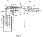
- Fig. 2 and Fig. 3 are diagrams illustrating an internal structure of the robot arm mechanism in Fig. 1 .
- the robot arm mechanism includes a substantially cylindrical base 1 and an arm section 2 connected to the base 1.
- An end effector 3 is attached to a tip of the arm section 2.
- a hand section capable of holding an object is shown as the end effector 3.
- the end effector 3 is not limited to the hand section, but may be another tool, a camera, or a display.
- an adapter which can be replaced with any type of the hand end effector 3 may be provided.
- the arm section 2 includes a plurality (herein, six) of joints J1, J2, J3, J4, J5 and J6.
- the plurality of the joints J1, J2, J3, J4, J5 and J6 are arranged in order from the base 1.
- a first axis RA1, a second axis RA2 and a third axis RA3 are called root three axes
- a fourth axis RA4, a fifth axis RA5 and a sixth axis RA6 are called wrist three axes for changing the posture of the hand section 3.
- At least one of the joints J1, J2 and J3 constituting root three axes is a linear motion joint.
- the third joint J3 is formed as a linear motion joint, in particular, a joint with a relatively long extension distance.
- the first joint J1 is a torsion joint that rotates on the first axis of rotation RA1 which is held, for example, perpendicularly to a base surface.
- the second joint J2 is a bending joint that rotates on the second axis of rotation RA2 perpendicular to the first axis of rotation RA1.
- the third joint J3 linearly extends or retracts along the third axis (axis of movement) RA3 perpendicular to the second axis of rotation RA2.
- the fourth joint J4 is a torsion joint that rotates on the fourth axis of rotation RA4 which matches the third axis of movement RA3.
- the fifth joint J5 is a bending joint that rotates on the fifth axis of rotation RA5 orthogonal to the fourth axis of rotation RA4.
- the sixth joint J6 is a bending joint that rotates on the sixth axis of rotation RA6 orthogonal to the fourth axis of rotation RA4 and perpendicular to the fifth axis of rotation RA5.
- the arm section 2 turns together with the hand section 3 in accordance with torsional rotation of the first joint J1.
- the arm section 2 rotates upward and downward on the second axis of rotation RA2 of the second joint J2 together with the hand section 3 in accordance with bending rotation of the second joint J2.
- An arm support body (first support body) 11a forming the base 1 has a cylindrical hollow structure formed around the axis of rotation RA1 of the first joint J1.
- the first joint J1 is mounted on a fixed base (not shown).
- the first support body 11a may be fixed on a ground plane. In this case, the arm section 2 turns independently of the first support body 11a.
- a second support body 11b is connected to an upper part of the first support body 11a.
- the second support body 11b has a hollow structure continuous to the first support body 11a.
- One end of the second support body 11b is attached to a rotating section of the first joint J1.
- the other end of the second support body 11b is opened, and a third support body 11c is set rotatably on the axis of rotation RA2 of the second joint J2.
- the third support body 11c has a scaly hollow structure communicating with the first support body 11a and the second support body 11b.
- a rear part of the third support body 11c is accommodated in or sent out from the second support body 11b.
- the rear part of the third joint J3, which constitutes a linear motion joint of the arm section 2 is housed inside the continuous hollow structure of the first support body 11a and the second support body 11b by retraction thereof.
- the inside of the hollow structure is called a storage section.
- the first joint J1 includes an annular fixed section and a rotating section, and is fixed to a base at the fixed section.
- the first support body 11a and the second support body 11b are attached to the rotating section.
- the first joint J1 rotates, the first support body 11a, the second support body 11b and the third support body 11c turn around the first axis of rotation RA1 together with the arm section 2 and the hand section 3.
- the third support body 11c is set rotatably, at the lower part of its rear end, on the axis of rotation RA2 with respect to a lower side of an open end of the second support body 11b.
- the second joint J2 serving as a bending joint that rotates on the axis of rotation RA2 is formed.
- the arm section 2 rotates vertically, i.e., rotates upward and downward, on the axis of rotation RA2 of the second joint J2 together with the hand section 3.
- the axis of rotation RA2 of the second joint J2 is perpendicular to the first axis of rotation RA1 of the first joint J1 serving as a torsion joint.
- the third joint J3 serving as a joint section constitutes a main constituent of the arm section 2.
- the hand section 3 described above is provided at the tip of the arm section 2 as shown in Fig. 1 .
- the hand section 3 is moved to a given position by the firstjoint J1, the secondjoint J2 and the third joint J3, and placed in a given posture by the fourth joint J4, the fifth joint J5 and the sixth joint J6.
- the hand section 3 includes two fingers 16a and 16b configured to be opened and closed.
- the fourth joint J4 is a torsion joint having the axis of rotation RA4 which typically matches a center axis of the arm section 2 along the extension and retraction direction of the arm section 2, that is, the axis of movement RA3 of the third joint J3.
- the hand section 3 rotates on the axis of rotation RA4 from the fourth joint J4 to the tip thereof.
- the fifth joint J5 is a bending joint having an axis of rotation RA5 orthogonal to the axis of movement RA4 of the fourth joint J4.
- the sixth joint J6 is a bending joint having an axis of rotation RA6 orthogonal to the axis of rotation RA4 of the fourth joint J4 and perpendicular to the axis of rotation RA5 of the fifth joint J5.
- the hand 16 turns left and right.
- Rotation, bending, and extension and retraction of the first to sixth joints J1-J6 enable positioning a two-fingered hand 16 of the hand section 3 at a given position and posture.
- the linear extension and retraction distance of the third joint J3 enables the hand section 3 to act on an object in a wide range from a position close to the base 1 to a position far from the base 1.
- the third joint J3 is characterized by the linear extension and retraction distance realized by a linear extension and retraction arm mechanism constituting the third joint J3.
- the linear extension and retraction distance is achieved by the structure shown in Fig. 2 and Fig. 3 .
- the linear extension and retraction arm mechanism includes a first connection piece string 21 and a second connection piece string 20. In an alignment pose where the arm section 2 is horizontal, the first connection piece string 21 is located below the second connection piece string 20, and the second connection piece string 20 is located above the first connection piece string 21.
- the first connection piece string 21 includes a plurality of first connection pieces 23 having the same U-shaped cross section and connected to form a string by pins at their back surface parts.
- the first connection piece string 21 is bendable in its back surface direction BD but conversely not bendable in its front surface direction FD due to the shape of the cross section of the first connection piece 23 and connection positions by the pins. Therefore, the shape of the cross section of the first connection piece 23 may be a hollow square shape, an arc, etc. as well as the U shape.
- the second connection piece string 20 has a substantially flat plate shape with a width substantially equivalent to that of the first connection piece 23, and includes a plurality of second connection pieces 22 connected to form a string by pins in a bendable state in both the back surface direction BD and the front surface direction FD.
- the first connection piece string 21 is joined to the second connection piece string 20 at the tip of the first connection piece string 21 by a joining piece 26.
- the joining piece 26 has an integrated shape of the first connection piece 23 and the second connection piece 22.
- a linear gear 22a is formed on the inside of each of the second connection piece 22.
- the linear gears 22a are connected to form a continuous linear gear (rack) when the second connection piece 22 has a linear shape.
- the front side of the first connection piece 23 faces the back surface side of the second connection piece 22.
- the back surface side of the first connection piece 23 and the front side of the second connection piece 22 face the inner surface of the base 1, the second support body 11b or the third support body 11c.
- Fig. 3 is a view illustrating an internal structure of the robot arm mechanism in Fig. 1 , which is viewed from a cross sectional direction.
- the second connection piece 22 is sandwiched between a roller 291 and a drive gear 24a in an ejection section 29.
- the linear gear 22a is engaged with the drive gear 24a.
- a motor M1 is driven, and the drive gear 24a rotates forward, so that the second connection piece string 20 is sent out forward from the ejection section 29 together with the first connection piece string 21.
- the first connection piece string 21 and the second connection piece string 20 are sandwiched by the ejection section 29, and pressed against each other to be joined.
- the back surface side of the first connection piece 23 is joined to the back surface side of the second connection piece 22.
- the first connection piece string 21 and the second connection piece string 20 joined together are supported by the ejection section 29, and thus the joined state is maintained.
- the joined state between the first connection piece string 21 and the second connection piece string 20 is maintained, bending of the first connection piece string 21 and the second connection piece string 20 is restricted, whereby the first connection piece string 21 and the second connection piece string 20 constitute a columnar body having a certain rigidity.
- the joined columnar body (the first connection piece string 21 and the second connection piece string 20) is linearly sent out along the third axis of movement RA3 starting with the joining piece 26.
- the ejection section 29 has a rectangular cylindrical shape. The width of the hollow part is substantially equal to the width of the columnar body.
- a plurality of rollers 291 are rotatably provided to support the columnar body from the side.
- the ejection section 29 is fixed to the second support body 11c or the second support body 11b. Therefore, the ejection section 29 turns together with the arm section 2 and the hand section 3 around the first rotation axis RA1. In addition, the ejection section 29 rotates vertically, i.e., rotates upward and downward, together with the arm section 2 and the hand section 3 on the second axis of rotation RA2.
- the motor M1 When the arm is retracted, the motor M1 is driven, and the drive gear 24a rotates backward, so that the joined state of the second connection piece string 20 and the first connection piece string 21 is canceled in the ejection section 29, and they are separated from each other.
- the second connection piece string 20 and first connection piece string 21 separated from each other restore their bendable state , are bent in a direction along the first axis of rotation RA1, and are housed inside the storage section.
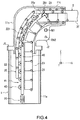
- FIG. 4 is a diagram illustrating a storage structure of the robot arm mechanism according to the present invention.
- a guide rail 41 includes a plurality of rail pieces 43 connected to form a string by pins. As shown in Fig. 4 , one end of the guide rail 41 is attached to a rear end portion of the ejection section 29 by using pinholes 431 and 432 of the leading rail piece 43. The other end of the guide rail 41 is fixed to one end of a spring 50 by using a pinhole 433 of the last rail piece 43. The other end of the spring 50 is fixed to the bottom of the base 1 (the first support body 11a) . The spring 50 extends and retracts in an axial direction of the base 1.
- a guide rail storage section 48 is fixed to the first support body 11a.
- the guide rail storage section 48 is fixed to an inner surface of the base 1.
- the guide rail storage section 48 is made of a pair of slide rails. Both ends of the rail piece 43 slide along the slide rail and are stored.
- the guide rail storage section 48 may be extended to the second support body 11b.
- Figs. 5A, 5B and 5C are diagrams illustrating a structure of the rail piece 43 of the robot arm mechanism according to the present invention.
- Figs. 5A, 5B and 5C show the rail piece 43 viewed in the orthogonal three axes directions.
- Figs. 5A, 5B and 5C show the rail piece 43 viewed from a side (+X direction), above (+Z direction), and below (+Y direction) direction, respectively.
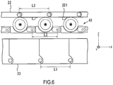
- Fig. 6 corresponds to Fig. 4 and is a diagram illustrating an actual positional relationship between the rail guide 41 and the first connection piece string 21 and the second connection piece string 20, which is viewed from a cross sectional direction.
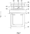
- Fig. 7 corresponds to Fig. 4 and is a diagram illustrating an actual positional relationship between the rail guide 41 and the first connection piece string 21 and the second connection piece string 20, which is viewed from a sending-out direction.
- the tip portion of the rail piece 43 has a concave shape with the pinholes 431 and 432 which are formed on both sides, and into which the pins for connection with the rear end portion of the rail piece 43 are inserted.
- the axial direction of the pinholes 431 and 432 is parallel to the width direction of the rail piece 43.
- Pinhole 431 has the same axial length as pinhole 432. The length obtained by adding the axial length of pinhole 432 to the axial length of pinhole 431 is shorter than the width of the rail piece 43.
- the rear end portion of the rail piece 43 has a convex shape with a pinhole 433 into which a pin for connection with the tip portion of the rail piece 43 is inserted.
- the axial direction of pinhole 433 is parallel to the width direction of the rail piece 43.
- the axial length of pinhole 433 is shorter than the width of the rail piece 43.
- the sum of the axial lengths of pinholes 431, 432 and 433 are substantially equal to the width of the rail piece 43.
- the sum of the axial lengths of pinholes 431,432 and 433 may be any length as long as it is equal to or less than the width of the rail piece 43.
- the length L3 from pinholes 431 and 432 at the tip to pinhole 433 at the rear end of the rail piece 43 is smaller than the length L2 from the pinhole at the tip to the pinhole at the rear end of the second connection piece 22.
- the first connection piece string 21, the second connection piece string 20 and the guide rail 41 are rotated on the second axis of rotation RA2.
- the guide rail 41 is located inside the second connection piece string 20. Therefore, the length L3 of the rail piece 43 is shorter than the length L2 of the second connection piece 22, so that the track of the guide rail 41 can be smoother than that of the second connection piece string 20.
- the guide rail 41 can smoothly guide the second connection piece string 20 to the ejection section 20.
- the length L1 from the pinhole at the tip to the pinhole at the rear end of the first connection piece 23 is substantially equal to the length L2 from the pinhole at the tip to the pinhole at the rear end of the second connection piece 22.
- the width W3 of the rail piece 43 is longer than the width W1 of the first connection piece 23 and the width W2 of the second connection piece 22.
- the width W1 of the first connection piece 23 is equal to the width W2 of the second connection piece 22.
- the width W3 of the rail piece 43 is 1.05 to 1.5 times greater than the width W1 of the first connection piece 23. Therefore, for example, even when the first connection piece 23 and the second connection piece 22 deviate in the width direction for some reason, interference between the first connection piece 23 and the second connection piece can be prevented by the rail piece 43.
- a shaft hole 434 is formed in the surface near the middle point of the rail piece 43 in the length direction.
- the axial direction of the shaft hole 434 is parallel to the width direction of the rail piece 43.
- the middle point in the axial direction of the shaft hole 434 matches the middle point in the width direction of the rail piece 43.
- the shaft hole 434 is shorter than the width W2 of the second connection piece 22, and preferably, as shown in Fig. 7 , the axial length of the shaft hole 434 is approximately equal to the length from the outer side surface of one of two lock sections 221 provided on the back surface of the second connection piece 22 to the outer side surface of the other one.
- a shaft 435 longer than the shaft hole 434 is inserted into the shaft hole 434.
- Wheels 437 and 438 are fixed to both ends of the shaft435, respectively.
- the surface of wheel 437 is covered with an elastic body such as rubber. The damage of the second connection piece 22 due to contact between the wheels 437 and 438 and the second connection piece 22 can be thereby prevented.
- Wheel 437 has a width shorter than the distance from the side surface of the second connection piece 22 to the outer side surface of the lock section 221 provided on the back surface of the second connection piece 22. Further, the wheel 437 has a radius longer than the distance from the back surface of the second connection piece 22 to the lower end of the lock section 221.
- Wheel 438 has the same shape as wheel 437.
- a depression is formed from both ends of the shaft hole 434 to the side surface of the rail piece 43.
- the depth from the hole center of the shaft hole 434 to the bottom surface of the depression is slightly deeper than the radius of the wheels 437 and 438.
- the length from the hole center of the shaft hole 434 to the end of the depression in the length direction is slightly longer than the radius of the wheels 437 and 438. Accordingly, the wheels 437 and 438 fixed to the both ends of the shaft 435 can rotate without interfering with the rail piece 43.
- the depression has an arc shape when the rail piece 43 is viewed from its side.
- a projection length from the surface of the rail piece 43 towards the second connection piece 22 is substantially the same as the radius of the wheels 437 and 438.
- Figs. 8 and 8C are diagrams illustrating a structure of the guide rail 41 of the robot arm mechanism according to the present invention.
- Fig. 8A shows the guide rail 41 in a posture in which the arm section 2 is horizontally arranged (hereinafter, referred to as a horizontal posture) .
- Fig. 8B shows the guide rail 41 in a posture in which the arm section 2 is lowered from the posture in Fig. 8A by a predetermined angle (hereinafter, referred to as a lowered posture).
- the guide rail 41 has flexibility. Specifically, the guide rail 41 is not bendable in the front surface direction and is bendable in the back surface direction.
- the bending angle ⁇ max in the back surface direction is limited.
- the bending angle of a connection portion is limited by the pin connecting two rail pieces 43.
- the bending angle of the connection portion may be limited by the shape of the pieces at the connection portion.
- the guide rail storage section 48 has a function of limiting a bendable range of the guide rail 41 in addition to the function of storing the guide rail 41 along the axial direction of the base 1. By prohibiting bending of the guide rail 41 stored in the base 1, it is possible to avoid the contact of the guide rail 41 with the first connection piece string 21. For example, let us assume that the posture changes from the horizontal posture to the lowered posture as shown in Fig. 8 . At this time, the guide rail 41 is pulled by the ejection section 29. The direction in which the guide rail 41 in the base 1 is pulled is not parallel to the axial direction of the base 1 but is a direction slightly inclined toward the first connection piece 21 side. If the entire guide rail 41 is bendable, the guide rail 41 may be inclined toward the first connection piece string 21 side.
- the guide rail 41 may come into contact with the first connection piece string 21 and disturb smooth sending of the first connection piece string 21.
- the guide rail 41 stored in the base 1 is stored in the guide rail storage section 48, the guide rail 41 is stored in the guide rail storage section 48 without being inclined regardless of how the guide rail 41 is pulled. Therefore, the guide rail 41 never comes into contact with the first connection piece string 21 and the second connection piece string 20.
- the guide rail 41 is unbendable in the front surface direction while being bendable in the back surface direction, and its bending angle ⁇ max is limited. Accordingly, the guide rail 41 can move along an arc shape around the second axis of rotation RA2. As shown in Figs. 8A and 8B , the bending angle ⁇ max is, for example, the exterior angle of when an arc 12 around the second axis of rotation RA2 with radius r2 is arranged in contact with the guide rail 41 having length L3.
- Radius r2 may be determined based on the distance from the rotation center of the second axis of rotation RA2 to a fixed point P29 of the guide rail 41 in the ejection section 29 and the distance from the rotation center of the second axis of rotation RA2 to a tip P48 of the guide rail storage section 48.
- the bending angle ⁇ max may be determined to allow a gentle track to be formed from a fixed position of the guide rail 41 at the rear end of the ejection section 29 to the tip of the guide rail storage section 48, not by a geometric method as described above. Accordingly, even when the arm section 2 rotates upward or downward, as the guide rail 41 bends in a limited angle range, the guide rail 41 can move along a predesignated track.
- the guide rail 41 can bend only within the limited angle range, the guide rail 41 has a certain rigidity. Since the arm section 2 rotates upward or downward only in the front surface direction of the guide rail 41, the guide rail 41 may be bendable in the front surface direction. In this case, there is a higher possibility that the guide rail 41 does not follow the track designed in advance than in the case where bending in the surface direction is impossible.
- the track of the guide rail 41 in the base 1 is determined by the guide rail storage section 48.
- the track of the guide rail 41 from the tip portion of the guide rail storage section 48 to the rear end of the ejection section 29 is designed in advance in accordance with the bending angle ⁇ max of the guide rail 41. Therefore, even when the arm section 2 rotates upward or downward, the guide rail 41 is arranged between the first connection piece string 21 and the second connection piece string 20. Therefore, the guide rail 41 can separately store the second connection piece string 20 and the first connection piece string 21 separated in the ejection section 29. Accordingly, it is possible to prevent the second connection piece string 20 from interfering with the first connection piece string 21.
- the guide rail 41 can guide the second connection piece string 20 to the ejection section 29 along the track designed in advance (in the sending-out direction) even when the arm section 2 rotates upward or downward.
- Figs. 9A and 9B are supplementary explanation diagrams illustrating an effect of the guide rail 41 of the robot arm mechanism according to the present invention.
- Figs. 9A and 9B are diagrams illustrating a difference of tracks (hereinafter, referred to as guide tracks) for guiding the second connection piece string 20 to the ejection section 29 caused by the presence or absence of the guide rail 41.
- Fig. 9A shows a guide track of the second connection piece string 20 of the case where the guide rail 41 is not provided.
- Fig. 9B shows a guide track of the second connection piece string 20 of the case where the guide rail 41 is provided.
- the second connection piece string 20 is stored in the storage section along the axial direction of the base 1.
- the second connection piece string 20 is necessary to rotate on the second axis of rotation RA2 from the stored state before being sent out from the ejection section 29.
- the arm section 2 is in the horizontal posture, the arm section 2 is sent out in a direction orthogonal to the axial direction of the base 1. Therefore, the second connection piece string 20 is guided to the ejection section 29 after rotating 90 degrees on the second axis of rotation RA2 from the state of being stored in the storage section. Then, the second connection piece string 20 is joined to the first connection piece string 21 in the ejection section 29 and is sent out together with the first connection piece string 21 toward the front side of the ejection section 29. At this time, the guide rail 41 guides the second connection piece string 20 to the ejection section 29 along the track designed in advance. Its effect is described with reference to Figs. 9A and 9B .
- Figs. 9A and 9B show three consecutive second connection pieces 225, 226, and 227. Described herein is the track along which second connection piece 226 is rotated by 90 degrees from the stored state to be guided to the drive gear 24a inside the ejection section 29.
- Fig. 9A shows the case where the guide rail 41 is not provided.
- Fig. 9B shows the case where the guide rail 41 is provided.
- States t1-t6 indicate the change in the state of the second connection pieces 225, 226 and 227 made each time the drive gear 24a rotates by a step angle and the arm section 2 moves by ⁇ d in the sending-out direction.
- State t1 is a state in which the linear gear 22a of the second connection piece 225 is engaged with the drive gear 24a.
- the drive gear 24a is engaged with the linear gear 22a of the second connection piece 225 at position P.
- the states between t1 and t4 show the second connection piece 225 being sent out in the sending-out direction by the drive gear 24a.
- the state t4 is a state immediately after the drive gear 24a is engaged with the linear gear 22a of the second connection piece 226 at position P.
- States t5 and t6 show the second connection piece 226 being sent out by the drive gear 24a.
- the second connection piece 226 rotates largely at the moment when the linear gear 22a of the second connection piece 226 is engaged with the drive gear 24a at position P. This is because the second connection piece 226 is guided little by little along a tangent of the drive gear 24a until it is engaged with the drive gear 24a and, at the moment when the second connection piece 226 is engaged with the drive gear 24a, the second connection piece 226 is rotated by the angle ⁇ 41 from the position immediately before the moment of the engagement (state t3) to the horizontal position (state t4) .
- the rotation angle ⁇ 42 at the moment when the linear gear 22a of the second connection piece 226 is engaged with the drive gear 24a at position P is smaller than the rotation angle ⁇ 41 of the case without the guide rail 41. Namely, at the moment when the linear gear 22a of the second connection piece 226 is engaged with the drive gear 24a, the second connection piece 226 does not largely rotate. This is because the second connection piece 226 is guided by the guide rail 41 and can be horizontal to some extent immediately before the linear gear 22a of the second connection piece 226 is engaged with the drive gear 24a (state t3).
- the second connection piece 226 rotates by ⁇ 21 in state t2, ⁇ 31 in state t3 and ⁇ 41 in state t4, and rotates by 90 degrees in total.
- the second connection piece 226 rotates by ⁇ 12 in state t1, ⁇ 22 in state t2, ⁇ 32 in state t3, ⁇ 42 in state t4, ⁇ 52 in state t5 and ⁇ 62 in state t6, and rotates by 90 degrees in total.
- the guide rail 41 can be arranged along a track designed in advance.
- the track of the guide rail 41 can be designed based on the bending angle of the guide rail storage section 48 and the guide rail 41.
- the first connection piece string 21 and the second connection piece string 20 can be thereby separated from each other and stored in the storage section.
- the second connection piece string 20 can be guided along the guide rail 41 designed in advance to the ejection section 29 (in the sending-out direction).
- the guide rail 41 can disperse the rotation of the second connection piece string 20 which is required for being sent out toward the front side of the ejection section 29 from the stored state. Since the angle of rotation per unit time can be reduced, it is possible to prevent the second connection piece 22 from rotating quickly. As a result, the second connection piece 22 can be prevented from colliding against the inner surface of the second support body 11b, and it is also possible to prevent occurrence of a collision sound and impairment of the second connection piece 22.
Description
- Embodiments described herein relate to a robot arm mechanism.
- Conventionally, an articulated robot arm mechanism is used in various fields such as an industrial robot. For example, the robot arm mechanism is provided with a linear extension and retraction joint in combination with other joints. An arm section constituting the linear extension and retraction joint includes, for example, a first connection piece string and a second connection piece string. The first connection piece string and the second connection piece string are stored in a storage section. When a motor rotates forward to drive the linear motion joint, the first connection piece string and the second connection piece string stored in the storage section are joined and sent out as a columnar body. When the motor rotates backward, the arm section is pulled back to the storage section, and the columnar body is separated into the first connection piece string and the second connection piece string to be stored in the storage section. In such a robot arm mechanism, the first connection piece string may collide against the second connection piece string in the storage section if no countermeasure is taken. Document
US2013/0068061 discloses a similar articulated robot arm mechanism. - A purpose of the present invention is to prevent a first connection piece string from colliding against a second connection piece string in a robot arm mechanism including a linear extension and retraction joint.
- The robot arm mechanism according to the present embodiment includes a linear extension and retraction joint, the linear extension and retraction joint includes an arm section, and an ejection section for supporting the arm section, the arm section includes a first connection piece string and a second connection piece string, the first connection piece string includes a plurality of first connection pieces each having a U-shaped cross section, a hollow square cross section or an arc cross section, the second connection piece string includes a plurality of second connection pieces each having a substantially flat plate shape, the second connection piece string is sent out forward from the ejection section together with the first connection piece string in a state where the second connection piece string is joined to the first connection piece string, and a flexible guide rail for separating the first connection piece string from the second connection piece string and guiding the second connection piece string to the ejection section is interposed between the first connection piece string and the second connection piece string behind the ejection section.
-
-
Fig. 1 is an external perspective view of a robot arm mechanism according to an embodiment; -
Fig. 2 is a perspective view illustrating an internal structure of the robot arm mechanism inFig. 1 ; -
Fig. 3 is a view illustrating an internal structure of the robot arm mechanism inFig. 1 , which is a cross section view; -
Fig. 4 is a diagram illustrating a storage structure of the robot arm mechanism according to the present embodiment; -
Figs. 5A, 5B and 5C are diagrams illustrating a rail piece of the robot arm mechanism according to the present embodiment; -
Fig. 6 is a diagram corresponding toFig. 4 and illustrating an actual positional relationship between the rail guide, a first connection piece string, and a second connection piece string, which is viewed from a cross sectional direction; -
Fig. 7 is a diagram corresponding toFig. 4 and illustrating an actual positional relationship between the rail guide, the first connection piece string, and the second connection piece string, which is viewed in a sending-out direction; -
Figs. 8A and 8B are diagrams illustrating a structure of the guide rail of the robot arm mechanism according to the present embodiment; and -
Figs. 9A and 9B are supplementary explanatory diagrams illustrating an effect of the guide rail of the robot arm mechanism according to the present embodiment. - Hereinafter, a robot arm mechanism according to the present embodiment is described with reference to the accompanying drawings. In the following description, the same reference numerals denote components having substantially identical functions and structures, and the repeated description thereof is made only when necessary.
-
Fig. 1 is an external perspective view of the robot arm mechanism according to the present embodiment.Fig. 2 andFig. 3 are diagrams illustrating an internal structure of the robot arm mechanism inFig. 1 . The robot arm mechanism includes a substantiallycylindrical base 1 and anarm section 2 connected to thebase 1. Anend effector 3 is attached to a tip of thearm section 2. InFig. 1 , a hand section capable of holding an object is shown as theend effector 3. Theend effector 3 is not limited to the hand section, but may be another tool, a camera, or a display. At the tip of thearm section 2, an adapter which can be replaced with any type of thehand end effector 3 may be provided. - The
arm section 2 includes a plurality (herein, six) of joints J1, J2, J3, J4, J5 and J6. The plurality of the joints J1, J2, J3, J4, J5 and J6 are arranged in order from thebase 1. Generally, a first axis RA1, a second axis RA2 and a third axis RA3 are called root three axes, and a fourth axis RA4, a fifth axis RA5 and a sixth axis RA6 are called wrist three axes for changing the posture of thehand section 3. At least one of the joints J1, J2 and J3 constituting root three axes is a linear motion joint. Herein, the third joint J3 is formed as a linear motion joint, in particular, a joint with a relatively long extension distance. The first joint J1 is a torsion joint that rotates on the first axis of rotation RA1 which is held, for example, perpendicularly to a base surface. The second joint J2 is a bending joint that rotates on the second axis of rotation RA2 perpendicular to the first axis of rotation RA1. The third joint J3 linearly extends or retracts along the third axis (axis of movement) RA3 perpendicular to the second axis of rotation RA2. The fourth joint J4 is a torsion joint that rotates on the fourth axis of rotation RA4 which matches the third axis of movement RA3. The fifth joint J5 is a bending joint that rotates on the fifth axis of rotation RA5 orthogonal to the fourth axis of rotation RA4. The sixth joint J6 is a bending joint that rotates on the sixth axis of rotation RA6 orthogonal to the fourth axis of rotation RA4 and perpendicular to the fifth axis of rotation RA5. - The
arm section 2 turns together with thehand section 3 in accordance with torsional rotation of the first joint J1. Thearm section 2 rotates upward and downward on the second axis of rotation RA2 of the second joint J2 together with thehand section 3 in accordance with bending rotation of the second joint J2. An arm support body (first support body) 11a forming thebase 1 has a cylindrical hollow structure formed around the axis of rotation RA1 of the first joint J1. The first joint J1 is mounted on a fixed base (not shown). When the first joint J1 rotates, thefirst support body 11a axially rotates in accordance with the turn of thearm section 2. Thefirst support body 11a may be fixed on a ground plane. In this case, thearm section 2 turns independently of thefirst support body 11a. Asecond support body 11b is connected to an upper part of thefirst support body 11a. - The
second support body 11b has a hollow structure continuous to thefirst support body 11a. One end of thesecond support body 11b is attached to a rotating section of the first joint J1. The other end of thesecond support body 11b is opened, and athird support body 11c is set rotatably on the axis of rotation RA2 of the second joint J2. Thethird support body 11c has a scaly hollow structure communicating with thefirst support body 11a and thesecond support body 11b. In accordance with the bending rotation of the second joint J2, a rear part of thethird support body 11c is accommodated in or sent out from thesecond support body 11b. The rear part of the third joint J3, which constitutes a linear motion joint of thearm section 2, is housed inside the continuous hollow structure of thefirst support body 11a and thesecond support body 11b by retraction thereof. The inside of the hollow structure is called a storage section. - The first joint J1 includes an annular fixed section and a rotating section, and is fixed to a base at the fixed section. The
first support body 11a and thesecond support body 11b are attached to the rotating section. When the first joint J1 rotates, thefirst support body 11a, thesecond support body 11b and thethird support body 11c turn around the first axis of rotation RA1 together with thearm section 2 and thehand section 3. - The
third support body 11c is set rotatably, at the lower part of its rear end, on the axis of rotation RA2 with respect to a lower side of an open end of thesecond support body 11b. In this way, the second joint J2 serving as a bending joint that rotates on the axis of rotation RA2 is formed. When the second joint J2 rotates, thearm section 2 rotates vertically, i.e., rotates upward and downward, on the axis of rotation RA2 of the second joint J2 together with thehand section 3. The axis of rotation RA2 of the second joint J2 is perpendicular to the first axis of rotation RA1 of the first joint J1 serving as a torsion joint. - As described above, the third joint J3 serving as a joint section constitutes a main constituent of the
arm section 2. Thehand section 3 described above is provided at the tip of thearm section 2 as shown inFig. 1 . Thehand section 3 is moved to a given position by the firstjoint J1, the secondjoint J2 and the third joint J3, and placed in a given posture by the fourth joint J4, the fifth joint J5 and the sixth joint J6. Thehand section 3 includes twofingers arm section 2 along the extension and retraction direction of thearm section 2, that is, the axis of movement RA3 of the third joint J3. When the fourth joint J4 rotates, thehand section 3 rotates on the axis of rotation RA4 from the fourth joint J4 to the tip thereof. - The fifth joint J5 is a bending joint having an axis of rotation RA5 orthogonal to the axis of movement RA4 of the fourth joint J4. When the fifth joint rotates, the
hand section 3 pivots up and down from the fifth joint J5 to its tip together with thehand 16. The sixth joint J6 is a bending joint having an axis of rotation RA6 orthogonal to the axis of rotation RA4 of the fourth joint J4 and perpendicular to the axis of rotation RA5 of the fifth joint J5. When the sixth joint J6 rotates, thehand 16 turns left and right. - Rotation, bending, and extension and retraction of the first to sixth joints J1-J6 enable positioning a two-fingered
hand 16 of thehand section 3 at a given position and posture. In particular, the linear extension and retraction distance of the third joint J3 enables thehand section 3 to act on an object in a wide range from a position close to thebase 1 to a position far from thebase 1. - The third joint J3 is characterized by the linear extension and retraction distance realized by a linear extension and retraction arm mechanism constituting the third joint J3. The linear extension and retraction distance is achieved by the structure shown in
Fig. 2 andFig. 3 . The linear extension and retraction arm mechanism includes a firstconnection piece string 21 and a secondconnection piece string 20. In an alignment pose where thearm section 2 is horizontal, the firstconnection piece string 21 is located below the secondconnection piece string 20, and the secondconnection piece string 20 is located above the firstconnection piece string 21. - The first
connection piece string 21 includes a plurality offirst connection pieces 23 having the same U-shaped cross section and connected to form a string by pins at their back surface parts. The firstconnection piece string 21 is bendable in its back surface direction BD but conversely not bendable in its front surface direction FD due to the shape of the cross section of thefirst connection piece 23 and connection positions by the pins. Therefore, the shape of the cross section of thefirst connection piece 23 may be a hollow square shape, an arc, etc. as well as the U shape. - The second
connection piece string 20 has a substantially flat plate shape with a width substantially equivalent to that of thefirst connection piece 23, and includes a plurality ofsecond connection pieces 22 connected to form a string by pins in a bendable state in both the back surface direction BD and the front surface direction FD. The firstconnection piece string 21 is joined to the secondconnection piece string 20 at the tip of the firstconnection piece string 21 by a joiningpiece 26. The joiningpiece 26 has an integrated shape of thefirst connection piece 23 and thesecond connection piece 22. As shown inFig. 2 , alinear gear 22a is formed on the inside of each of thesecond connection piece 22. Thelinear gears 22a are connected to form a continuous linear gear (rack) when thesecond connection piece 22 has a linear shape. The front side of thefirst connection piece 23 faces the back surface side of thesecond connection piece 22. The back surface side of thefirst connection piece 23 and the front side of thesecond connection piece 22 face the inner surface of thebase 1, thesecond support body 11b or thethird support body 11c. -
Fig. 3 is a view illustrating an internal structure of the robot arm mechanism inFig. 1 , which is viewed from a cross sectional direction. - As shown in
Fig. 3 , thesecond connection piece 22 is sandwiched between aroller 291 and adrive gear 24a in anejection section 29. Thelinear gear 22a is engaged with thedrive gear 24a. When the arm is extended, a motor M1 is driven, and thedrive gear 24a rotates forward, so that the secondconnection piece string 20 is sent out forward from theejection section 29 together with the firstconnection piece string 21. At that time, the firstconnection piece string 21 and the secondconnection piece string 20 are sandwiched by theejection section 29, and pressed against each other to be joined. At this time, the back surface side of thefirst connection piece 23 is joined to the back surface side of thesecond connection piece 22. The firstconnection piece string 21 and the secondconnection piece string 20 joined together are supported by theejection section 29, and thus the joined state is maintained. When the joined state between the firstconnection piece string 21 and the secondconnection piece string 20 is maintained, bending of the firstconnection piece string 21 and the secondconnection piece string 20 is restricted, whereby the firstconnection piece string 21 and the secondconnection piece string 20 constitute a columnar body having a certain rigidity. Then, the joined columnar body (the firstconnection piece string 21 and the second connection piece string 20) is linearly sent out along the third axis of movement RA3 starting with the joiningpiece 26. Theejection section 29 has a rectangular cylindrical shape. The width of the hollow part is substantially equal to the width of the columnar body. On the side surface thereof, a plurality ofrollers 291 are rotatably provided to support the columnar body from the side. Theejection section 29 is fixed to thesecond support body 11c or thesecond support body 11b. Therefore, theejection section 29 turns together with thearm section 2 and thehand section 3 around the first rotation axis RA1. In addition, theejection section 29 rotates vertically, i.e., rotates upward and downward, together with thearm section 2 and thehand section 3 on the second axis of rotation RA2. - When the arm is retracted, the motor M1 is driven, and the
drive gear 24a rotates backward, so that the joined state of the secondconnection piece string 20 and the firstconnection piece string 21 is canceled in theejection section 29, and they are separated from each other. The secondconnection piece string 20 and firstconnection piece string 21 separated from each other restore their bendable state , are bent in a direction along the first axis of rotation RA1, and are housed inside the storage section. -
Fig. 4 is a diagram illustrating a storage structure of the robot arm mechanism according to the present invention. Aguide rail 41 includes a plurality ofrail pieces 43 connected to form a string by pins. As shown inFig. 4 , one end of theguide rail 41 is attached to a rear end portion of theejection section 29 by usingpinholes rail piece 43. The other end of theguide rail 41 is fixed to one end of aspring 50 by using apinhole 433 of thelast rail piece 43. The other end of thespring 50 is fixed to the bottom of the base 1 (thefirst support body 11a) . Thespring 50 extends and retracts in an axial direction of thebase 1. A guiderail storage section 48 is fixed to thefirst support body 11a. The guiderail storage section 48 is fixed to an inner surface of thebase 1. The guiderail storage section 48 is made of a pair of slide rails. Both ends of therail piece 43 slide along the slide rail and are stored. The guiderail storage section 48 may be extended to thesecond support body 11b. - Next, the plurality of the
rail pieces 43 constituting theguide rail 41 are described with reference toFigs. 5 ,6 and7 . -
Figs. 5A, 5B and 5C are diagrams illustrating a structure of therail piece 43 of the robot arm mechanism according to the present invention.Figs. 5A, 5B and 5C show therail piece 43 viewed in the orthogonal three axes directions.Figs. 5A, 5B and 5C show therail piece 43 viewed from a side (+X direction), above (+Z direction), and below (+Y direction) direction, respectively. -
Fig. 6 corresponds toFig. 4 and is a diagram illustrating an actual positional relationship between therail guide 41 and the firstconnection piece string 21 and the secondconnection piece string 20, which is viewed from a cross sectional direction. -
Fig. 7 corresponds toFig. 4 and is a diagram illustrating an actual positional relationship between therail guide 41 and the firstconnection piece string 21 and the secondconnection piece string 20, which is viewed from a sending-out direction. - As shown in
Figs. 5A, 5B and 5C , the tip portion of therail piece 43 has a concave shape with thepinholes rail piece 43 are inserted. The axial direction of thepinholes rail piece 43.Pinhole 431 has the same axial length aspinhole 432. The length obtained by adding the axial length ofpinhole 432 to the axial length ofpinhole 431 is shorter than the width of therail piece 43. The rear end portion of therail piece 43 has a convex shape with apinhole 433 into which a pin for connection with the tip portion of therail piece 43 is inserted. The axial direction ofpinhole 433 is parallel to the width direction of therail piece 43. The axial length ofpinhole 433 is shorter than the width of therail piece 43. The sum of the axial lengths ofpinholes rail piece 43. However, the sum of the axial lengths of pinholes 431,432 and 433 may be any length as long as it is equal to or less than the width of therail piece 43. When the tip of a rail piece is fitted to the rear end of theadjacent rail piece 43, pinholes 431,432 and 433 form a single pinhole in a straight line. By inserting a single pin into the single pinhole, theadjacent rail pieces 43 are connected. - As shown in
Fig. 6 , the length L3 frompinholes rail piece 43 is smaller than the length L2 from the pinhole at the tip to the pinhole at the rear end of thesecond connection piece 22. As shown inFig. 4 , the firstconnection piece string 21, the secondconnection piece string 20 and theguide rail 41 are rotated on the second axis of rotation RA2. At that time, theguide rail 41 is located inside the secondconnection piece string 20. Therefore, the length L3 of therail piece 43 is shorter than the length L2 of thesecond connection piece 22, so that the track of theguide rail 41 can be smoother than that of the secondconnection piece string 20. As a result, theguide rail 41 can smoothly guide the secondconnection piece string 20 to theejection section 20. The length L1 from the pinhole at the tip to the pinhole at the rear end of thefirst connection piece 23 is substantially equal to the length L2 from the pinhole at the tip to the pinhole at the rear end of thesecond connection piece 22. - As shown in
Fig. 7 , the width W3 of therail piece 43 is longer than the width W1 of thefirst connection piece 23 and the width W2 of thesecond connection piece 22. The width W1 of thefirst connection piece 23 is equal to the width W2 of thesecond connection piece 22. For example, the width W3 of therail piece 43 is 1.05 to 1.5 times greater than the width W1 of thefirst connection piece 23. Therefore, for example, even when thefirst connection piece 23 and thesecond connection piece 22 deviate in the width direction for some reason, interference between thefirst connection piece 23 and the second connection piece can be prevented by therail piece 43. - As shown in
Figs. 5A, 5B and 5C , ashaft hole 434 is formed in the surface near the middle point of therail piece 43 in the length direction. The axial direction of theshaft hole 434 is parallel to the width direction of therail piece 43. The middle point in the axial direction of theshaft hole 434 matches the middle point in the width direction of therail piece 43. Theshaft hole 434 is shorter than the width W2 of thesecond connection piece 22, and preferably, as shown inFig. 7 , the axial length of theshaft hole 434 is approximately equal to the length from the outer side surface of one of twolock sections 221 provided on the back surface of thesecond connection piece 22 to the outer side surface of the other one. Ashaft 435 longer than theshaft hole 434 is inserted into theshaft hole 434.Wheels wheel 437 is covered with an elastic body such as rubber. The damage of thesecond connection piece 22 due to contact between thewheels second connection piece 22 can be thereby prevented.Wheel 437 has a width shorter than the distance from the side surface of thesecond connection piece 22 to the outer side surface of thelock section 221 provided on the back surface of thesecond connection piece 22. Further, thewheel 437 has a radius longer than the distance from the back surface of thesecond connection piece 22 to the lower end of thelock section 221.Wheel 438 has the same shape aswheel 437. - A depression is formed from both ends of the
shaft hole 434 to the side surface of therail piece 43. The depth from the hole center of theshaft hole 434 to the bottom surface of the depression is slightly deeper than the radius of thewheels shaft hole 434 to the end of the depression in the length direction is slightly longer than the radius of thewheels wheels shaft 435 can rotate without interfering with therail piece 43. For example, the depression has an arc shape when therail piece 43 is viewed from its side. - A projection length from the surface of the
rail piece 43 towards thesecond connection piece 22 is substantially the same as the radius of thewheels rail piece 43 is brought into contact with thesecond connection piece 22, thepieces rail piece 43 are in contact with the back surface of thesecond connection piece 22 and are not in contact with thelock section 221. - Next, a structure of the
guide rail 41 is described. -
Figs. 8 and 8C are diagrams illustrating a structure of theguide rail 41 of the robot arm mechanism according to the present invention.Fig. 8A shows theguide rail 41 in a posture in which thearm section 2 is horizontally arranged (hereinafter, referred to as a horizontal posture) .Fig. 8B shows theguide rail 41 in a posture in which thearm section 2 is lowered from the posture inFig. 8A by a predetermined angle (hereinafter, referred to as a lowered posture). - As shown in
Figs. 8A and 8B , when thearm section 2 changes from the horizontal posture to the lowered posture, theejection section 29 rotates on the second axis of rotation RA2 by a predetermined angle. In accordance with the rotation, theguide rail 41 is pulled by theejection section 2. When a pulling force is exerted on theguide rail 41 by theejection section 29, thespring 50 is extended, and theguide rail 41 is pulled out from the guiderail storage section 48. On the other hand, when thearm section 2 returns from the lowered posture to the horizontal posture, theguide rail 41 pulled out from the guiderail storage section 48 is stored in the guiderail storage section 48. At this time, a pushing force is exerted on theguide rail 41 by thespring 50, whereby theguide rail 41 can be smoothly stored in the guiderail storage section 48. The rear end of theguide rail 41 may be free. At this time, the effect of thespring 50 as described above cannot be produced. - The
guide rail 41 has flexibility. Specifically, theguide rail 41 is not bendable in the front surface direction and is bendable in the back surface direction. The bending angle θmax in the back surface direction is limited. The bending angle of a connection portion is limited by the pin connecting tworail pieces 43. The bending angle of the connection portion may be limited by the shape of the pieces at the connection portion. - The guide
rail storage section 48 has a function of limiting a bendable range of theguide rail 41 in addition to the function of storing theguide rail 41 along the axial direction of thebase 1. By prohibiting bending of theguide rail 41 stored in thebase 1, it is possible to avoid the contact of theguide rail 41 with the firstconnection piece string 21. For example, let us assume that the posture changes from the horizontal posture to the lowered posture as shown inFig. 8 . At this time, theguide rail 41 is pulled by theejection section 29. The direction in which theguide rail 41 in thebase 1 is pulled is not parallel to the axial direction of thebase 1 but is a direction slightly inclined toward thefirst connection piece 21 side. If theentire guide rail 41 is bendable, theguide rail 41 may be inclined toward the firstconnection piece string 21 side. Thus, theguide rail 41 may come into contact with the firstconnection piece string 21 and disturb smooth sending of the firstconnection piece string 21. When theguide rail 41 stored in thebase 1 is stored in the guiderail storage section 48, theguide rail 41 is stored in the guiderail storage section 48 without being inclined regardless of how theguide rail 41 is pulled. Therefore, theguide rail 41 never comes into contact with the firstconnection piece string 21 and the secondconnection piece string 20. - On the other hand, bending of the
guide rail 41 is permitted from the tip of the guiderail storage section 48 to theejection section 29. The bendable angle of theguide rail 41 is limited. Specifically, theguide rail 41 is unbendable in the front surface direction while being bendable in the back surface direction, and its bending angle θmax is limited. Accordingly, theguide rail 41 can move along an arc shape around the second axis of rotation RA2. As shown inFigs. 8A and 8B , the bending angle θmax is, for example, the exterior angle of when anarc 12 around the second axis of rotation RA2 with radius r2 is arranged in contact with theguide rail 41 having length L3. Radius r2 may be determined based on the distance from the rotation center of the second axis of rotation RA2 to a fixed point P29 of theguide rail 41 in theejection section 29 and the distance from the rotation center of the second axis of rotation RA2 to a tip P48 of the guiderail storage section 48. The bending angle θmax may be determined to allow a gentle track to be formed from a fixed position of theguide rail 41 at the rear end of theejection section 29 to the tip of the guiderail storage section 48, not by a geometric method as described above. Accordingly, even when thearm section 2 rotates upward or downward, as theguide rail 41 bends in a limited angle range, theguide rail 41 can move along a predesignated track. Since theguide rail 41 can bend only within the limited angle range, theguide rail 41 has a certain rigidity. Since thearm section 2 rotates upward or downward only in the front surface direction of theguide rail 41, theguide rail 41 may be bendable in the front surface direction. In this case, there is a higher possibility that theguide rail 41 does not follow the track designed in advance than in the case where bending in the surface direction is impossible. - As stated above, the track of the
guide rail 41 in thebase 1 is determined by the guiderail storage section 48. The track of theguide rail 41 from the tip portion of the guiderail storage section 48 to the rear end of theejection section 29 is designed in advance in accordance with the bending angle θmax of theguide rail 41. Therefore, even when thearm section 2 rotates upward or downward, theguide rail 41 is arranged between the firstconnection piece string 21 and the secondconnection piece string 20. Therefore, theguide rail 41 can separately store the secondconnection piece string 20 and the firstconnection piece string 21 separated in theejection section 29. Accordingly, it is possible to prevent the secondconnection piece string 20 from interfering with the firstconnection piece string 21. Theguide rail 41 can guide the secondconnection piece string 20 to theejection section 29 along the track designed in advance (in the sending-out direction) even when thearm section 2 rotates upward or downward. -
Figs. 9A and 9B are supplementary explanation diagrams illustrating an effect of theguide rail 41 of the robot arm mechanism according to the present invention.Figs. 9A and 9B are diagrams illustrating a difference of tracks (hereinafter, referred to as guide tracks) for guiding the secondconnection piece string 20 to theejection section 29 caused by the presence or absence of theguide rail 41.Fig. 9A shows a guide track of the secondconnection piece string 20 of the case where theguide rail 41 is not provided.Fig. 9B shows a guide track of the secondconnection piece string 20 of the case where theguide rail 41 is provided. In the robot arm mechanism according to the present embodiment, the secondconnection piece string 20 is stored in the storage section along the axial direction of thebase 1. The secondconnection piece string 20 is necessary to rotate on the second axis of rotation RA2 from the stored state before being sent out from theejection section 29. For example, when thearm section 2 is in the horizontal posture, thearm section 2 is sent out in a direction orthogonal to the axial direction of thebase 1. Therefore, the secondconnection piece string 20 is guided to theejection section 29 after rotating 90 degrees on the second axis of rotation RA2 from the state of being stored in the storage section. Then, the secondconnection piece string 20 is joined to the firstconnection piece string 21 in theejection section 29 and is sent out together with the firstconnection piece string 21 toward the front side of theejection section 29. At this time, theguide rail 41 guides the secondconnection piece string 20 to theejection section 29 along the track designed in advance. Its effect is described with reference toFigs. 9A and 9B . -
Figs. 9A and 9B show three consecutivesecond connection pieces second connection piece 226 is rotated by 90 degrees from the stored state to be guided to thedrive gear 24a inside theejection section 29.Fig. 9A shows the case where theguide rail 41 is not provided.Fig. 9B shows the case where theguide rail 41 is provided. States t1-t6 indicate the change in the state of thesecond connection pieces drive gear 24a rotates by a step angle and thearm section 2 moves by Δd in the sending-out direction. State t1 is a state in which thelinear gear 22a of thesecond connection piece 225 is engaged with thedrive gear 24a. Thedrive gear 24a is engaged with thelinear gear 22a of thesecond connection piece 225 at position P. The states between t1 and t4 show thesecond connection piece 225 being sent out in the sending-out direction by thedrive gear 24a. The state t4 is a state immediately after thedrive gear 24a is engaged with thelinear gear 22a of thesecond connection piece 226 at position P. States t5 and t6 show thesecond connection piece 226 being sent out by thedrive gear 24a. - It can be understood that, without the guide rail 41 (
Fig. 9A ), thesecond connection piece 226 rotates largely at the moment when thelinear gear 22a of thesecond connection piece 226 is engaged with thedrive gear 24a at position P. This is because thesecond connection piece 226 is guided little by little along a tangent of thedrive gear 24a until it is engaged with thedrive gear 24a and, at the moment when thesecond connection piece 226 is engaged with thedrive gear 24a, thesecond connection piece 226 is rotated by the angle θ41 from the position immediately before the moment of the engagement (state t3) to the horizontal position (state t4) . In other words, without theguide rail 41, the rotation angle of 90 degrees necessary for thesecond connection piece 226 to change from the stored state to the horizontal state cannot be dispersed as intended, which inevitably causes the case where thesecond connection piece 226 instantaneously rotates largely. Therefore, as in state t4, when the angle θ41 by which thesecond connection piece 226 rotates at the moment when thesecond connection piece 226 is brought into the horizontal state is large, thesecond connection piece 226 rotates quickly, and thesecond connection piece 226 may collide with thesecond support body 11b. As a result, a collision sound may occur, or a problem such as thesecond connection piece 226 is scraped off may occur. - With the guide rail 41 (
Fig. 9B ), the rotation angle θ42 at the moment when thelinear gear 22a of thesecond connection piece 226 is engaged with thedrive gear 24a at position P is smaller than the rotation angle θ41 of the case without theguide rail 41. Namely, at the moment when thelinear gear 22a of thesecond connection piece 226 is engaged with thedrive gear 24a, thesecond connection piece 226 does not largely rotate. This is because thesecond connection piece 226 is guided by theguide rail 41 and can be horizontal to some extent immediately before thelinear gear 22a of thesecond connection piece 226 is engaged with thedrive gear 24a (state t3). In other words, by using theguide rail 41, it is possible to intentionally disperse the rotation angle of 90 degrees necessary for thesecond connection piece 226 to change from the stored state to the horizontal state. Specifically, without theguide rail 41, thesecond connection piece 226 rotates by θ21 in state t2, θ31 in state t3 and θ41 in state t4, and rotates by 90 degrees in total. On the other hand, with theguide rail 41, thesecond connection piece 226 rotates by θ12 in state t1, θ22 in state t2, θ32 in state t3, θ42 in state t4, θ52 in state t5 and θ62 in state t6, and rotates by 90 degrees in total. Therefore, by using theguide rail 41, it is possible to reduce the angle at which thesecond connection piece 22 rotates per unit time, and it is possible to prevent a large rotation at a certain moment. Therefore, as in state t4, by reducing the angle θ42 by which thesecond connection piece 226 rotates at the moment when thesecond connection piece 226 is brought into the horizontal state, it is possible to suppress the rotational momentum of thesecond connection piece 226, and it is also possible to prevent thesecond connection piece 226 from colliding against the inner surface of thesecondsupport body 11b. Accordingly, it is possible to prevent occurrence of a collision sound and a damage of thesecond connection piece 226. - According to the robot arm mechanism according to the present invention as described above, even when the
arm section 2 rotates upward and downward, theguide rail 41 can be arranged along a track designed in advance. The track of theguide rail 41 can be designed based on the bending angle of the guiderail storage section 48 and theguide rail 41. The firstconnection piece string 21 and the secondconnection piece string 20 can be thereby separated from each other and stored in the storage section. As a result, it is possible to prevent the secondconnection piece string 20 from interfering with the firstconnection piece string 21. Furthermore, according to the robot arm mechanism according to the present invention, the secondconnection piece string 20 can be guided along theguide rail 41 designed in advance to the ejection section 29 (in the sending-out direction). Specifically, theguide rail 41 can disperse the rotation of the secondconnection piece string 20 which is required for being sent out toward the front side of theejection section 29 from the stored state. Since the angle of rotation per unit time can be reduced, it is possible to prevent thesecond connection piece 22 from rotating quickly. As a result, thesecond connection piece 22 can be prevented from colliding against the inner surface of thesecond support body 11b, and it is also possible to prevent occurrence of a collision sound and impairment of thesecond connection piece 22.
Claims (5)
- A robot arm mechanism comprising a linear extension and retraction joint, wherein
the linear extension and retraction joint includes an arm section (2), and an ejection section (29) for supporting the arm section,
the arm section includes a first connection piece string (21) and a second connection piece string (20),
the first connection piece string (21) includes a plurality of first connection pieces (23) each having a U-shaped cross section, a hollow square cross section or an arc cross section, and the second connection piece string (20)includes a plurality of second connection pieces (22) each having a substantially flat plate shape,
the second connection piece string (20) is sent out forward from the ejection section together with the first connection piece string (21) in a state where the second connection piece string (20) is joined to the first connection piece string (21), and
a flexible guide rail (41) for separating the first connection piece string (21) from the second connection piece string (20) and guiding the second connection piece string (20) to the ejection section is interposed between the first connection piece string (21) and the second connection piece string (20) behind the ejection section, characterized in that:the flexible guide rail (41) includes a plurality of rail pieces (43) connected in a row, andthe rail pieces (43) are provided with wheels (437, 438). - The robot arm mechanism according to claim 1, wherein a bending angle of the guide rail (41) to the first connection piece string side is limited.
- The robot arm mechanism according to claim 2, wherein the guide rail (41) is unbendable to the second connection piece string side.
- The robot arm mechanism according to claim 1, wherein a surface of the wheels (437, 438) is covered with an elastic body.
- The robot arm mechanism according to claim 1, wherein a length of a rail piece (43) is shorter than that of the second connection piece (22).
Applications Claiming Priority (2)
| Application Number | Priority Date | Filing Date | Title |
|---|---|---|---|
| JP2014242673A JP6508704B2 (en) | 2014-11-29 | 2014-11-29 | Robot arm mechanism |
| PCT/JP2015/083430 WO2016084943A1 (en) | 2014-11-29 | 2015-11-27 | Robot arm mechanism |
Publications (3)
| Publication Number | Publication Date |
|---|---|
| EP3225367A1 EP3225367A1 (en) | 2017-10-04 |
| EP3225367A4 EP3225367A4 (en) | 2018-08-08 |
| EP3225367B1 true EP3225367B1 (en) | 2019-09-04 |
Family
ID=56074488
Family Applications (1)
| Application Number | Title | Priority Date | Filing Date |
|---|---|---|---|
| EP15862345.4A Not-in-force EP3225367B1 (en) | 2014-11-29 | 2015-11-27 | Robot arm mechanism |
Country Status (6)
| Country | Link |
|---|---|
| US (1) | US10131058B2 (en) |
| EP (1) | EP3225367B1 (en) |
| JP (1) | JP6508704B2 (en) |
| CN (1) | CN107000221B (en) |
| TW (1) | TW201628808A (en) |
| WO (1) | WO2016084943A1 (en) |
Families Citing this family (16)
| Publication number | Priority date | Publication date | Assignee | Title |
|---|---|---|---|---|
| JP6468804B2 (en) * | 2014-10-30 | 2019-02-13 | ライフロボティクス株式会社 | Robot arm mechanism |
| JP2016117127A (en) | 2014-12-20 | 2016-06-30 | ライフロボティクス株式会社 | Robot arm mechanism |
| JP2016124068A (en) * | 2014-12-27 | 2016-07-11 | ライフロボティクス株式会社 | Robot arm mechanism and direct-acting expansion mechanism |
| JP2016136060A (en) * | 2015-01-24 | 2016-07-28 | ライフロボティクス株式会社 | Linear motion telescopic mechanism and robot arm mechanism |
| JP6605847B2 (en) * | 2015-06-05 | 2019-11-13 | ライフロボティクス株式会社 | Robot arm mechanism |
| DE112016005469T5 (en) * | 2015-11-30 | 2018-08-09 | Life Robotics Inc. | Linear motion telescopic mechanism |
| CN108698236A (en) * | 2016-02-29 | 2018-10-23 | 生活机器人学股份有限公司 | Mechanical arm mechanism and direct acting telescoping mechanism |
| WO2017150315A1 (en) * | 2016-02-29 | 2017-09-08 | ライフロボティクス株式会社 | Direct-acting extension/retraction mechanism, and robot arm mechanism provided with same |
| JP6773768B2 (en) * | 2016-03-29 | 2020-10-21 | ライフロボティクス株式会社 | Torsion rotary joint mechanism and robot arm mechanism |
| JP6725645B2 (en) * | 2016-03-29 | 2020-07-22 | ライフロボティクス株式会社 | Robot arm mechanism |
| JP2019162670A (en) * | 2016-07-30 | 2019-09-26 | ライフロボティクス株式会社 | Robot arm mechanism |
| CN109562523B (en) * | 2016-07-30 | 2022-03-15 | 生活机器人学股份有限公司 | Mechanical arm mechanism |
| US20200353630A1 (en) * | 2017-12-06 | 2020-11-12 | Currence Robotics As | Robot picking assembly |
| CN108556965B (en) * | 2018-01-29 | 2023-08-11 | 上汽大众汽车有限公司 | Hybrid power battery part mounting method and mounting equipment |
| CN111000635B (en) * | 2019-12-06 | 2020-09-18 | 河南省肿瘤医院 | Mechanical arm mechanism for tumor resection |
| JP7314857B2 (en) * | 2020-04-30 | 2023-07-26 | トヨタ自動車株式会社 | Telescopic mechanism and moving body |
Family Cites Families (18)
| Publication number | Priority date | Publication date | Assignee | Title |
|---|---|---|---|---|
| SE419421B (en) * | 1979-03-16 | 1981-08-03 | Ove Larson | RESIDENTIAL ARM IN SPECIAL ROBOT ARM |
| US4473365A (en) * | 1980-11-26 | 1984-09-25 | Lapeyre James M | Detachable link chain |
| JPH0429660A (en) * | 1990-05-25 | 1992-01-31 | Asahi Okuma Ind Co Ltd | Reciprocation moving device |
| JPH053300A (en) | 1990-10-05 | 1993-01-08 | Nippon Steel Corp | Semiconductor device |
| JPH0750400Y2 (en) * | 1991-07-03 | 1995-11-15 | 住友金属工業株式会社 | Transfer device |
| JPH07116986A (en) * | 1993-10-22 | 1995-05-09 | Mitsubishi Electric Corp | Industrial robot |
| GB9617538D0 (en) * | 1996-08-21 | 1996-10-02 | Weatherford Oil Tool | Positioning device |
| DE29706739U1 (en) * | 1997-04-15 | 1997-06-12 | Grasl Andreas Ing | Device for transmitting a force, in particular a compressive force, along an essentially straight line |
| JP3898182B2 (en) * | 2003-12-17 | 2007-03-28 | 学校法人東京理科大学 | Telescopic mechanism |
| US7621078B2 (en) * | 2005-01-20 | 2009-11-24 | Drs Sustainment Systems, Inc. | Telescoping mast having variable height locking and a chain erection mechanism with a cable management system |
| US7258521B2 (en) * | 2005-05-31 | 2007-08-21 | Scriptpro Llc | Chain-driven robotic arm |
| WO2010070915A1 (en) * | 2008-12-19 | 2010-06-24 | 株式会社川渕機械技術研究所 | Linearly moving extendable mechanism and robot arm equipped with linearly moving extendable mechanism |
| JP2011144832A (en) * | 2010-01-12 | 2011-07-28 | Tsubakimoto Chain Co | Engagement chain type advancing and retreating device |
| WO2011152265A1 (en) * | 2010-05-31 | 2011-12-08 | 独立行政法人産業技術総合研究所 | Direct acting extensible and retractable arm mechanism, and robot arm provided with direct acting extensible and retractable arm mechanism |
| US8899359B1 (en) * | 2010-11-05 | 2014-12-02 | The Boeing Company | Locomotion system for robotic snake |
| US9294737B2 (en) * | 2012-08-23 | 2016-03-22 | Siemens Energy, Inc. | Flexible linkage camera system and method for visual inspection of off line industrial gas turbines and other power generation machinery |
| JP2014139482A (en) * | 2014-04-22 | 2014-07-31 | Ntn Corp | Chain guide |
| JP6468804B2 (en) * | 2014-10-30 | 2019-02-13 | ライフロボティクス株式会社 | Robot arm mechanism |
-
2014
- 2014-11-29 JP JP2014242673A patent/JP6508704B2/en active Active
-
2015
- 2015-11-27 CN CN201580064927.4A patent/CN107000221B/en not_active Withdrawn - After Issue
- 2015-11-27 WO PCT/JP2015/083430 patent/WO2016084943A1/en active Application Filing
- 2015-11-27 EP EP15862345.4A patent/EP3225367B1/en not_active Not-in-force
- 2015-11-27 TW TW104139713A patent/TW201628808A/en unknown
-
2017
- 2017-05-25 US US15/605,376 patent/US10131058B2/en active Active
Non-Patent Citations (1)
| Title |
|---|
| None * |
Also Published As
| Publication number | Publication date |
|---|---|
| WO2016084943A1 (en) | 2016-06-02 |
| CN107000221B (en) | 2020-04-14 |
| JP2016101652A (en) | 2016-06-02 |
| CN107000221A (en) | 2017-08-01 |
| JP6508704B2 (en) | 2019-05-08 |
| EP3225367A1 (en) | 2017-10-04 |
| US10131058B2 (en) | 2018-11-20 |
| US20170266819A1 (en) | 2017-09-21 |
| TW201628808A (en) | 2016-08-16 |
| EP3225367A4 (en) | 2018-08-08 |
Similar Documents
| Publication | Publication Date | Title |
|---|---|---|
| EP3225367B1 (en) | Robot arm mechanism | |
| US10406697B2 (en) | Robot arm mechanism | |
| CN107148328B (en) | Mechanical arm mechanism | |
| EP3210729B1 (en) | Robot arm mechanism | |
| JP6659846B2 (en) | Robot arm mechanism | |
| WO2016104807A1 (en) | Robot arm mechanism and linearly moving extendable mechanism | |
| EP3249259A1 (en) | Coupling segment, direct-acting extension/retraction mechanism, and robot arm mechanism | |
| EP3235609A1 (en) | Robot arm mechanism | |
| EP3238891A1 (en) | Robot arm mechanism and linearly moving extendable mechanism | |
| US20170320217A1 (en) | Linear extension and retraction mechanism, and robot arm mechanism | |
| EP3242057A1 (en) | Linear-motion extending/contracting mechanism and robot arm mechanism | |
| JP6748179B2 (en) | Robot arm mechanism | |
| JP2016160962A (en) | Warping expansion mechanism and robot arm mechanism | |
| JP2016160963A (en) | Warping expansion mechanism and robot arm mechanism | |
| JP2016168646A (en) | Straight-motion extension and contraction mechanism and robot arm mechanism | |
| JP2016101645A (en) | Robot arm mechanism |
Legal Events
| Date | Code | Title | Description |
|---|---|---|---|
| STAA | Information on the status of an ep patent application or granted ep patent |
Free format text: STATUS: THE INTERNATIONAL PUBLICATION HAS BEEN MADE |
|
| PUAI | Public reference made under article 153(3) epc to a published international application that has entered the european phase |
Free format text: ORIGINAL CODE: 0009012 |
|
| STAA | Information on the status of an ep patent application or granted ep patent |
Free format text: STATUS: REQUEST FOR EXAMINATION WAS MADE |
|
| 17P | Request for examination filed |
Effective date: 20170628 |
|
| AK | Designated contracting states |
Kind code of ref document: A1 Designated state(s): AL AT BE BG CH CY CZ DE DK EE ES FI FR GB GR HR HU IE IS IT LI LT LU LV MC MK MT NL NO PL PT RO RS SE SI SK SM TR |
|
| AX | Request for extension of the european patent |
Extension state: BA ME |
|
| DAV | Request for validation of the european patent (deleted) | ||
| DAX | Request for extension of the european patent (deleted) | ||
| A4 | Supplementary search report drawn up and despatched |
Effective date: 20180710 |
|
| RIC1 | Information provided on ipc code assigned before grant |
Ipc: B25J 17/00 20060101ALI20180704BHEP Ipc: F16G 13/20 20060101ALI20180704BHEP Ipc: B25J 18/02 20060101AFI20180704BHEP Ipc: F16H 19/02 20060101ALI20180704BHEP |
|
| RIC1 | Information provided on ipc code assigned before grant |
Ipc: B25J 17/00 20060101ALI20190206BHEP Ipc: B25J 18/02 20060101AFI20190206BHEP Ipc: F16H 19/02 20060101ALI20190206BHEP Ipc: F16G 13/20 20060101ALI20190206BHEP |
|
| GRAP | Despatch of communication of intention to grant a patent |
Free format text: ORIGINAL CODE: EPIDOSNIGR1 |
|
| STAA | Information on the status of an ep patent application or granted ep patent |
Free format text: STATUS: GRANT OF PATENT IS INTENDED |
|
| INTG | Intention to grant announced |
Effective date: 20190404 |
|
| RIN1 | Information on inventor provided before grant (corrected) |
Inventor name: YOON, WOO-KEUN |
|
| GRAS | Grant fee paid |
Free format text: ORIGINAL CODE: EPIDOSNIGR3 |
|
| GRAA | (expected) grant |
Free format text: ORIGINAL CODE: 0009210 |
|
| STAA | Information on the status of an ep patent application or granted ep patent |
Free format text: STATUS: THE PATENT HAS BEEN GRANTED |
|
| AK | Designated contracting states |
Kind code of ref document: B1 Designated state(s): AL AT BE BG CH CY CZ DE DK EE ES FI FR GB GR HR HU IE IS IT LI LT LU LV MC MK MT NL NO PL PT RO RS SE SI SK SM TR |
|
| REG | Reference to a national code |
Ref country code: GB Ref legal event code: FG4D |
|
| REG | Reference to a national code |
Ref country code: CH Ref legal event code: EP |
|
| REG | Reference to a national code |
Ref country code: AT Ref legal event code: REF Ref document number: 1174723 Country of ref document: AT Kind code of ref document: T Effective date: 20190915 |
|
| REG | Reference to a national code |
Ref country code: DE Ref legal event code: R096 Ref document number: 602015037487 Country of ref document: DE |
|
| REG | Reference to a national code |
Ref country code: IE Ref legal event code: FG4D |
|
| REG | Reference to a national code |
Ref country code: NL Ref legal event code: MP Effective date: 20190904 |
|
| REG | Reference to a national code |
Ref country code: LT Ref legal event code: MG4D |
|
| PG25 | Lapsed in a contracting state [announced via postgrant information from national office to epo] |
Ref country code: BG Free format text: LAPSE BECAUSE OF FAILURE TO SUBMIT A TRANSLATION OF THE DESCRIPTION OR TO PAY THE FEE WITHIN THE PRESCRIBED TIME-LIMIT Effective date: 20191204 Ref country code: SE Free format text: LAPSE BECAUSE OF FAILURE TO SUBMIT A TRANSLATION OF THE DESCRIPTION OR TO PAY THE FEE WITHIN THE PRESCRIBED TIME-LIMIT Effective date: 20190904 Ref country code: NO Free format text: LAPSE BECAUSE OF FAILURE TO SUBMIT A TRANSLATION OF THE DESCRIPTION OR TO PAY THE FEE WITHIN THE PRESCRIBED TIME-LIMIT Effective date: 20191204 Ref country code: LT Free format text: LAPSE BECAUSE OF FAILURE TO SUBMIT A TRANSLATION OF THE DESCRIPTION OR TO PAY THE FEE WITHIN THE PRESCRIBED TIME-LIMIT Effective date: 20190904 Ref country code: FI Free format text: LAPSE BECAUSE OF FAILURE TO SUBMIT A TRANSLATION OF THE DESCRIPTION OR TO PAY THE FEE WITHIN THE PRESCRIBED TIME-LIMIT Effective date: 20190904 Ref country code: HR Free format text: LAPSE BECAUSE OF FAILURE TO SUBMIT A TRANSLATION OF THE DESCRIPTION OR TO PAY THE FEE WITHIN THE PRESCRIBED TIME-LIMIT Effective date: 20190904 |
|
| PG25 | Lapsed in a contracting state [announced via postgrant information from national office to epo] |
Ref country code: LV Free format text: LAPSE BECAUSE OF FAILURE TO SUBMIT A TRANSLATION OF THE DESCRIPTION OR TO PAY THE FEE WITHIN THE PRESCRIBED TIME-LIMIT Effective date: 20190904 Ref country code: GR Free format text: LAPSE BECAUSE OF FAILURE TO SUBMIT A TRANSLATION OF THE DESCRIPTION OR TO PAY THE FEE WITHIN THE PRESCRIBED TIME-LIMIT Effective date: 20191205 Ref country code: AL Free format text: LAPSE BECAUSE OF FAILURE TO SUBMIT A TRANSLATION OF THE DESCRIPTION OR TO PAY THE FEE WITHIN THE PRESCRIBED TIME-LIMIT Effective date: 20190904 Ref country code: RS Free format text: LAPSE BECAUSE OF FAILURE TO SUBMIT A TRANSLATION OF THE DESCRIPTION OR TO PAY THE FEE WITHIN THE PRESCRIBED TIME-LIMIT Effective date: 20190904 |
|
| REG | Reference to a national code |
Ref country code: AT Ref legal event code: MK05 Ref document number: 1174723 Country of ref document: AT Kind code of ref document: T Effective date: 20190904 |
|
| PG25 | Lapsed in a contracting state [announced via postgrant information from national office to epo] |
Ref country code: AT Free format text: LAPSE BECAUSE OF FAILURE TO SUBMIT A TRANSLATION OF THE DESCRIPTION OR TO PAY THE FEE WITHIN THE PRESCRIBED TIME-LIMIT Effective date: 20190904 Ref country code: IT Free format text: LAPSE BECAUSE OF FAILURE TO SUBMIT A TRANSLATION OF THE DESCRIPTION OR TO PAY THE FEE WITHIN THE PRESCRIBED TIME-LIMIT Effective date: 20190904 Ref country code: EE Free format text: LAPSE BECAUSE OF FAILURE TO SUBMIT A TRANSLATION OF THE DESCRIPTION OR TO PAY THE FEE WITHIN THE PRESCRIBED TIME-LIMIT Effective date: 20190904 Ref country code: NL Free format text: LAPSE BECAUSE OF FAILURE TO SUBMIT A TRANSLATION OF THE DESCRIPTION OR TO PAY THE FEE WITHIN THE PRESCRIBED TIME-LIMIT Effective date: 20190904 Ref country code: PL Free format text: LAPSE BECAUSE OF FAILURE TO SUBMIT A TRANSLATION OF THE DESCRIPTION OR TO PAY THE FEE WITHIN THE PRESCRIBED TIME-LIMIT Effective date: 20190904 Ref country code: RO Free format text: LAPSE BECAUSE OF FAILURE TO SUBMIT A TRANSLATION OF THE DESCRIPTION OR TO PAY THE FEE WITHIN THE PRESCRIBED TIME-LIMIT Effective date: 20190904 Ref country code: PT Free format text: LAPSE BECAUSE OF FAILURE TO SUBMIT A TRANSLATION OF THE DESCRIPTION OR TO PAY THE FEE WITHIN THE PRESCRIBED TIME-LIMIT Effective date: 20200106 |
|
| PG25 | Lapsed in a contracting state [announced via postgrant information from national office to epo] |
Ref country code: CZ Free format text: LAPSE BECAUSE OF FAILURE TO SUBMIT A TRANSLATION OF THE DESCRIPTION OR TO PAY THE FEE WITHIN THE PRESCRIBED TIME-LIMIT Effective date: 20190904 Ref country code: SK Free format text: LAPSE BECAUSE OF FAILURE TO SUBMIT A TRANSLATION OF THE DESCRIPTION OR TO PAY THE FEE WITHIN THE PRESCRIBED TIME-LIMIT Effective date: 20190904 Ref country code: SM Free format text: LAPSE BECAUSE OF FAILURE TO SUBMIT A TRANSLATION OF THE DESCRIPTION OR TO PAY THE FEE WITHIN THE PRESCRIBED TIME-LIMIT Effective date: 20190904 Ref country code: IS Free format text: LAPSE BECAUSE OF FAILURE TO SUBMIT A TRANSLATION OF THE DESCRIPTION OR TO PAY THE FEE WITHIN THE PRESCRIBED TIME-LIMIT Effective date: 20200224 |
|
| REG | Reference to a national code |
Ref country code: DE Ref legal event code: R097 Ref document number: 602015037487 Country of ref document: DE |
|
| REG | Reference to a national code |
Ref country code: CH Ref legal event code: PL |
|
| PLBE | No opposition filed within time limit |
Free format text: ORIGINAL CODE: 0009261 |
|
| STAA | Information on the status of an ep patent application or granted ep patent |
Free format text: STATUS: NO OPPOSITION FILED WITHIN TIME LIMIT |
|
| PG2D | Information on lapse in contracting state deleted |
Ref country code: IS |
|
| PG25 | Lapsed in a contracting state [announced via postgrant information from national office to epo] |
Ref country code: LI Free format text: LAPSE BECAUSE OF NON-PAYMENT OF DUE FEES Effective date: 20191130 Ref country code: LU Free format text: LAPSE BECAUSE OF NON-PAYMENT OF DUE FEES Effective date: 20191127 Ref country code: MC Free format text: LAPSE BECAUSE OF FAILURE TO SUBMIT A TRANSLATION OF THE DESCRIPTION OR TO PAY THE FEE WITHIN THE PRESCRIBED TIME-LIMIT Effective date: 20190904 Ref country code: DK Free format text: LAPSE BECAUSE OF FAILURE TO SUBMIT A TRANSLATION OF THE DESCRIPTION OR TO PAY THE FEE WITHIN THE PRESCRIBED TIME-LIMIT Effective date: 20190904 Ref country code: CH Free format text: LAPSE BECAUSE OF NON-PAYMENT OF DUE FEES Effective date: 20191130 Ref country code: IS Free format text: LAPSE BECAUSE OF FAILURE TO SUBMIT A TRANSLATION OF THE DESCRIPTION OR TO PAY THE FEE WITHIN THE PRESCRIBED TIME-LIMIT Effective date: 20200105 |
|
| 26N | No opposition filed |
Effective date: 20200605 |
|
| REG | Reference to a national code |
Ref country code: BE Ref legal event code: MM Effective date: 20191130 |
|
| PG25 | Lapsed in a contracting state [announced via postgrant information from national office to epo] |
Ref country code: SI Free format text: LAPSE BECAUSE OF FAILURE TO SUBMIT A TRANSLATION OF THE DESCRIPTION OR TO PAY THE FEE WITHIN THE PRESCRIBED TIME-LIMIT Effective date: 20190904 |
|
| GBPC | Gb: european patent ceased through non-payment of renewal fee |
Effective date: 20191204 |
|
| PG25 | Lapsed in a contracting state [announced via postgrant information from national office to epo] |
Ref country code: IE Free format text: LAPSE BECAUSE OF NON-PAYMENT OF DUE FEES Effective date: 20191127 Ref country code: ES Free format text: LAPSE BECAUSE OF FAILURE TO SUBMIT A TRANSLATION OF THE DESCRIPTION OR TO PAY THE FEE WITHIN THE PRESCRIBED TIME-LIMIT Effective date: 20190904 Ref country code: FR Free format text: LAPSE BECAUSE OF NON-PAYMENT OF DUE FEES Effective date: 20191130 Ref country code: GB Free format text: LAPSE BECAUSE OF NON-PAYMENT OF DUE FEES Effective date: 20191204 |
|
| PG25 | Lapsed in a contracting state [announced via postgrant information from national office to epo] |
Ref country code: BE Free format text: LAPSE BECAUSE OF NON-PAYMENT OF DUE FEES Effective date: 20191130 |
|
| PG25 | Lapsed in a contracting state [announced via postgrant information from national office to epo] |
Ref country code: CY Free format text: LAPSE BECAUSE OF FAILURE TO SUBMIT A TRANSLATION OF THE DESCRIPTION OR TO PAY THE FEE WITHIN THE PRESCRIBED TIME-LIMIT Effective date: 20190904 |
|
| PG25 | Lapsed in a contracting state [announced via postgrant information from national office to epo] |
Ref country code: HU Free format text: LAPSE BECAUSE OF FAILURE TO SUBMIT A TRANSLATION OF THE DESCRIPTION OR TO PAY THE FEE WITHIN THE PRESCRIBED TIME-LIMIT; INVALID AB INITIO Effective date: 20151127 Ref country code: MT Free format text: LAPSE BECAUSE OF FAILURE TO SUBMIT A TRANSLATION OF THE DESCRIPTION OR TO PAY THE FEE WITHIN THE PRESCRIBED TIME-LIMIT Effective date: 20190904 |
|
| PG25 | Lapsed in a contracting state [announced via postgrant information from national office to epo] |
Ref country code: TR Free format text: LAPSE BECAUSE OF FAILURE TO SUBMIT A TRANSLATION OF THE DESCRIPTION OR TO PAY THE FEE WITHIN THE PRESCRIBED TIME-LIMIT Effective date: 20190904 |
|
| PG25 | Lapsed in a contracting state [announced via postgrant information from national office to epo] |
Ref country code: MK Free format text: LAPSE BECAUSE OF FAILURE TO SUBMIT A TRANSLATION OF THE DESCRIPTION OR TO PAY THE FEE WITHIN THE PRESCRIBED TIME-LIMIT Effective date: 20190904 |
|
| PGFP | Annual fee paid to national office [announced via postgrant information from national office to epo] |
Ref country code: DE Payment date: 20220621 Year of fee payment: 8 |
|
| REG | Reference to a national code |
Ref country code: DE Ref legal event code: R231 Ref document number: 602015037487 Country of ref document: DE |
|
| PG25 | Lapsed in a contracting state [announced via postgrant information from national office to epo] |
Ref country code: DE Free format text: LAPSE BECAUSE OF THE APPLICANT RENOUNCES Effective date: 20230727 |