WO2010070915A1 - Linearly moving extendable mechanism and robot arm equipped with linearly moving extendable mechanism - Google Patents
Linearly moving extendable mechanism and robot arm equipped with linearly moving extendable mechanism Download PDFInfo
- Publication number
- WO2010070915A1 WO2010070915A1 PCT/JP2009/006973 JP2009006973W WO2010070915A1 WO 2010070915 A1 WO2010070915 A1 WO 2010070915A1 JP 2009006973 W JP2009006973 W JP 2009006973W WO 2010070915 A1 WO2010070915 A1 WO 2010070915A1
- Authority
- WO
- WIPO (PCT)
- Prior art keywords
- arm
- block body
- linear motion
- rotary joint
- robot arm
- Prior art date
Links
Images


Classifications
-
- B—PERFORMING OPERATIONS; TRANSPORTING
- B25—HAND TOOLS; PORTABLE POWER-DRIVEN TOOLS; MANIPULATORS
- B25J—MANIPULATORS; CHAMBERS PROVIDED WITH MANIPULATION DEVICES
- B25J18/00—Arms
- B25J18/02—Arms extensible
- B25J18/025—Arms extensible telescopic
-
- B—PERFORMING OPERATIONS; TRANSPORTING
- B25—HAND TOOLS; PORTABLE POWER-DRIVEN TOOLS; MANIPULATORS
- B25J—MANIPULATORS; CHAMBERS PROVIDED WITH MANIPULATION DEVICES
- B25J18/00—Arms
- B25J18/06—Arms flexible
-
- B—PERFORMING OPERATIONS; TRANSPORTING
- B25—HAND TOOLS; PORTABLE POWER-DRIVEN TOOLS; MANIPULATORS
- B25J—MANIPULATORS; CHAMBERS PROVIDED WITH MANIPULATION DEVICES
- B25J9/00—Programme-controlled manipulators
- B25J9/02—Programme-controlled manipulators characterised by movement of the arms, e.g. cartesian coordinate type
- B25J9/04—Programme-controlled manipulators characterised by movement of the arms, e.g. cartesian coordinate type by rotating at least one arm, excluding the head movement itself, e.g. cylindrical coordinate type or polar coordinate type
- B25J9/045—Polar coordinate type
-
- B—PERFORMING OPERATIONS; TRANSPORTING
- B25—HAND TOOLS; PORTABLE POWER-DRIVEN TOOLS; MANIPULATORS
- B25J—MANIPULATORS; CHAMBERS PROVIDED WITH MANIPULATION DEVICES
- B25J9/00—Programme-controlled manipulators
- B25J9/02—Programme-controlled manipulators characterised by movement of the arms, e.g. cartesian coordinate type
- B25J9/04—Programme-controlled manipulators characterised by movement of the arms, e.g. cartesian coordinate type by rotating at least one arm, excluding the head movement itself, e.g. cylindrical coordinate type or polar coordinate type
- B25J9/046—Revolute coordinate type
-
- F—MECHANICAL ENGINEERING; LIGHTING; HEATING; WEAPONS; BLASTING
- F16—ENGINEERING ELEMENTS AND UNITS; GENERAL MEASURES FOR PRODUCING AND MAINTAINING EFFECTIVE FUNCTIONING OF MACHINES OR INSTALLATIONS; THERMAL INSULATION IN GENERAL
- F16G—BELTS, CABLES, OR ROPES, PREDOMINANTLY USED FOR DRIVING PURPOSES; CHAINS; FITTINGS PREDOMINANTLY USED THEREFOR
- F16G13/00—Chains
- F16G13/18—Chains having special overall characteristics
- F16G13/20—Chains having special overall characteristics stiff; Push-pull chains
-
- F—MECHANICAL ENGINEERING; LIGHTING; HEATING; WEAPONS; BLASTING
- F16—ENGINEERING ELEMENTS AND UNITS; GENERAL MEASURES FOR PRODUCING AND MAINTAINING EFFECTIVE FUNCTIONING OF MACHINES OR INSTALLATIONS; THERMAL INSULATION IN GENERAL
- F16H—GEARING
- F16H19/00—Gearings comprising essentially only toothed gears or friction members and not capable of conveying indefinitely-continuing rotary motion
- F16H19/02—Gearings comprising essentially only toothed gears or friction members and not capable of conveying indefinitely-continuing rotary motion for interconverting rotary or oscillating motion and reciprocating motion
- F16H19/06—Gearings comprising essentially only toothed gears or friction members and not capable of conveying indefinitely-continuing rotary motion for interconverting rotary or oscillating motion and reciprocating motion comprising flexible members, e.g. an endless flexible member
- F16H19/0636—Gearings comprising essentially only toothed gears or friction members and not capable of conveying indefinitely-continuing rotary motion for interconverting rotary or oscillating motion and reciprocating motion comprising flexible members, e.g. an endless flexible member the flexible member being a non-buckling chain
-
- F—MECHANICAL ENGINEERING; LIGHTING; HEATING; WEAPONS; BLASTING
- F16—ENGINEERING ELEMENTS AND UNITS; GENERAL MEASURES FOR PRODUCING AND MAINTAINING EFFECTIVE FUNCTIONING OF MACHINES OR INSTALLATIONS; THERMAL INSULATION IN GENERAL
- F16H—GEARING
- F16H25/00—Gearings comprising primarily only cams, cam-followers and screw-and-nut mechanisms
- F16H25/18—Gearings comprising primarily only cams, cam-followers and screw-and-nut mechanisms for conveying or interconverting oscillating or reciprocating motions
- F16H25/20—Screw mechanisms
- F16H25/24—Elements essential to such mechanisms, e.g. screws, nuts
- F16H25/2409—Elements essential to such mechanisms, e.g. screws, nuts one of the threads being replaced by elements specially formed for engaging the screw or nut, e.g. pins, racks, toothed belts
-
- Y—GENERAL TAGGING OF NEW TECHNOLOGICAL DEVELOPMENTS; GENERAL TAGGING OF CROSS-SECTIONAL TECHNOLOGIES SPANNING OVER SEVERAL SECTIONS OF THE IPC; TECHNICAL SUBJECTS COVERED BY FORMER USPC CROSS-REFERENCE ART COLLECTIONS [XRACs] AND DIGESTS
- Y10—TECHNICAL SUBJECTS COVERED BY FORMER USPC
- Y10T—TECHNICAL SUBJECTS COVERED BY FORMER US CLASSIFICATION
- Y10T74/00—Machine element or mechanism
- Y10T74/18—Mechanical movements
- Y10T74/18056—Rotary to or from reciprocating or oscillating
- Y10T74/18152—Belt or chain carried member
-
- Y—GENERAL TAGGING OF NEW TECHNOLOGICAL DEVELOPMENTS; GENERAL TAGGING OF CROSS-SECTIONAL TECHNOLOGIES SPANNING OVER SEVERAL SECTIONS OF THE IPC; TECHNICAL SUBJECTS COVERED BY FORMER USPC CROSS-REFERENCE ART COLLECTIONS [XRACs] AND DIGESTS
- Y10—TECHNICAL SUBJECTS COVERED BY FORMER USPC
- Y10T—TECHNICAL SUBJECTS COVERED BY FORMER US CLASSIFICATION
- Y10T74/00—Machine element or mechanism
- Y10T74/20—Control lever and linkage systems
- Y10T74/20207—Multiple controlling elements for single controlled element
- Y10T74/20305—Robotic arm
- Y10T74/20329—Joint between elements
Definitions
- the present invention relates to a linear motion expansion / contraction mechanism, and more specifically, a typical robot arm having an elbow joint is unavoidable, and safety is eliminated without the risk of pinching surrounding objects when the elbow joint is closed.
- the present invention relates to a linear motion expansion / contraction mechanism that realizes a smaller footprint and a robot arm equipped with the same.
- robot arms have been used in cooperation with people in production facilities, and are also used for assistance in maintaining and developing the quality of life of elderly and disabled people in daily life.
- FIGS. 27A and 27B there is a form including an arm portion 102 in which a rotary joint 103 is connected in series between a base portion 100 and an end effector 101.
- a rotary joint 103 is connected in series between a base portion 100 and an end effector 101.
- FIG. 27 (b) when it is short and contracted as shown in FIG. 27 (b), it largely protrudes laterally from the line connecting the base 100 and the end effector 101 (broken line in the figure), so that it touches the surroundings. Or the risk of collision.
- there is a risk that a surrounding object is caught between the arm part 102 and the arm part 102. Therefore, it can be said that it is not suitable as a robot arm for welfare used in a daily living environment.
- FIG. 28 illustrates four types of telescopic robot arms having a “linear motion expansion / contraction mechanism” that realizes an arm function by linearly expanding and contracting the rod-shaped member.
- FIG. 28A is an image of a thin and ideal telescopic arm, and it is assumed that a mechanism for realizing some telescopic function is included in the bellows.
- Three of (b) to (d) in FIG. 28 are extendable arms that imitate the realized mechanism. In the case of these forms, since the space occupied by the arm portion is minimized as compared with the configuration of FIG.
- the volume of the part of the arm structure that is unnecessary in the contracted state (hereinafter referred to as the unnecessary part of the arm part), that is, the product of the thickness and the length, is quite bulky, and the base part depends on the volume required for its storage. And its vicinity will enlarge.
- the invention of the robot arm which is supposed to be used in an environment close to humans, greatly reduces the weight of the structure in order to minimize the pinching by the rotating joints and to minimize the impact during contact with humans. It becomes a problem.
- the present invention has been made to solve the above-described problems, and an object of the present invention is to provide a linear motion expansion / contraction mechanism and a robot arm that are assumed to be used in an environment close to a person at a distance.
- the inventors of the present application have found that by using a linear motion expansion / contraction mechanism composed of a plurality of block bodies as a robot arm, the danger of pinching, which has been a problem in the past, can be significantly reduced, and the present invention has been completed. It came.
- the linear motion expansion / contraction mechanism fixes a block body group composed of a plurality of block bodies and another block body to a certain block body or a fixed block.
- a block body moving means having a function of unfixing one block body from each other, and using the moving means, a part or all of the block bodies are removed from the block body group.
- the rigid arrangement can be arbitrarily changed in length by arranging it linearly and rigidly, or by unfixing part or all of the rigid arrangement so as to return to the individual block body. It is characterized by being configured as a rigid arm portion.
- the inventors of the present application have studied the pinching problem in the configuration shown in FIG. 27 and the linear motion expansion / contraction type robot arm exemplified in FIG. 28, and divided the rod-like arm portion into small blocks,
- the present invention has been completed by finding that an ideal robot arm can be realized by adopting an arm portion having a linear motion expansion / contraction mechanism that can greatly move a block corresponding to the unnecessary portion.
- the robot arm according to the present invention includes an installation unit fixed to a desk, a floor, or the like, and a support body connected via a first rotary joint that can rotate with respect to the installation unit.
- a uniaxial rod-shaped arm portion connected to the support body via a second rotary joint that can rotate in a direction orthogonal to the first rotary joint, and the other end of the arm portion.
- An end effector, and the arm part is a linear motion expansion / contraction mechanism that can expand and contract to a desired arm length, and is prepared in advance so that the required maximum arm length can be constructed.
- the part exceeding the desired arm length is separated from the arm part, and is separated from the central axis of the arm part along the extending direction of the arm part.
- Configured to be stored in an open space It is characterized by having a linear expansion mechanism being.
- the linear motion expansion / contraction mechanism fixes a block body group composed of a plurality of block bodies and another block body to a certain block body in order to solve the above-described problems.
- a block body moving means having a function of unfixing each block body from the fixed block bodies, and using the moving means, a part or all of the block body group
- the rigid array can be arbitrarily changed in length. It is characterized by being configured as a straight rigid arm portion.
- the robot arm according to the present invention includes an installation unit fixed to a desk or a floor and a first rotary joint that can rotate with respect to the installation unit in order to solve the above-described problem.
- a support body connected via the first rotation joint, a uniaxial rod-shaped arm section connected to the support body via a second rotation joint capable of rotating in a direction perpendicular to the first rotation joint, and the arm section
- An end effector provided at the other end of the arm, and the arm portion is a linear motion expansion / contraction mechanism capable of expanding and contracting so as to have a desired arm length.
- a part having a length exceeding the desired arm length is separated from the arm part, and the structure along the extending direction of the arm part is separated.
- Space outside the central axis of the arm is characterized in having a linear expansion mechanism configured to house.
- the inventors of the present application can remarkably reduce the danger of pinching described above by mounting a linear motion expansion / contraction mechanism that realizes a linear motion expansion / contraction joint using a plurality of block bodies on the arm portion of the robot arm.
- the present inventors have found that it is possible to reduce the occupied space and have completed the present invention.
- the robot arm equipped with the linear motion expansion / contraction mechanism according to the present invention can be used as an industrial robot arm, and also used as a welfare device such as an assistance robot that assists work in place of a human hand in daily life. be able to.
- the linear motion expansion / contraction mechanism fixes a block body group composed of a plurality of block bodies and another block body to a certain block body, or fixes one block body from each of the fixed block bodies.
- a block body moving means having a function of releasing, or using the moving means, a part or all of the block bodies are linearly and rigidly arranged from the block body group, or the rigid body
- the rigid arrangement is configured as a linear arm part whose length can be arbitrarily changed by unfixing a part or all of the simple arrangement so as to return to the individual block body. Yes.
- linear motion expansion / contraction mechanism according to the present invention will be described with reference to FIGS. 1 to 15 by taking a robot arm as an embodiment.
- the entire linear motion expansion / contraction mechanism may be regarded as one motion joint, which may be referred to as a linear motion expansion / contraction joint J3.
- FIG. 1 and 2 are perspective views showing the appearance of the robot arm.
- FIG. 1 shows a state in which the linear motion expansion / contraction joint J3 provided in the arm portion 2 of the robot arm 40 is shortened
- FIG. 2 shows a state in which the linear motion expansion / contraction joint J3 is extended.
- the robot arm 40 includes a support 1 (base), an arm 2, and a hand 3 (another structure, a gripper, and an end effector).
- the support 1 has a structure extending in the vertical direction from the installation surface G of the robot arm 40, and supports the entire robot arm 40.
- the support body 1 has two first support portions 10a and second support portions 10b, a first rotary joint J1, and a second rotary joint J2.
- the first support part 10a and the second support part 10b have a cylindrical shape and are arranged vertically so as to align the center axes (support axes) of each other.
- the 1st support part 10a and the 2nd support part 10b are hollow structures, and are comprised so that a part of component of the arm part 2 mentioned later can be accommodated in an inside.
- FIG. 3 is a cross-sectional view of the robot arm 40 taken along the cutting line AA ′ shown in FIG.
- the arm portion 2 has a linear motion expansion / contraction joint J3 shown in FIG. 3 and is a configuration for adjusting a desired position / posture of the hand portion 3 disposed at the tip of the arm portion 2.
- the hand unit 3 can be moved to a position far away from the support 1 to obtain the state shown in FIG.
- FIG. 4 is a cross-sectional view in the state of FIG. 2 in which the direct acting expansion joint J3 is extended.
- the main components of the arm unit 2 are a block body group 20 constituting the linear motion expansion / contraction joint J3 shown in FIG. 3 and a moving means (drive mechanism) 21 (FIG. 6) for driving the linear motion expansion / contraction joint J3. is there.
- the block body group 20 is composed of a plurality of block bodies 22 as shown in FIGS. 3 and 4, and all the block bodies 22 are arranged in series from the block body 22 at one end to the block body 22 at the other end. .
- FIG. 5 is a perspective view showing the external appearance of each block body 22.
- the block body 22 has a hollow structure penetrating in the connecting direction of the block bodies 22, and the internal space can be utilized as an optimal space for passing through while protecting the electrical wiring. It is configured.
- an upper surface uneven structure 22 b that meshes with a toothed belt described later is also provided on the upper surface of each block body 22.
- a rack gear-like bottom surface uneven structure 22 c is also provided on the bottom surface of each block body 22.
- the block body group 20 in which the block bodies having such a structure are arranged in series is partly arranged in series by being fixed by fixing the block bodies, and most of the rigid parts are It has the structure which protruded in the uniaxial direction toward the exterior from opening part 10b 'provided in the 2nd support part 10b.
- the remaining arrangement of the block groups 20 that are not rigid is housed in the second support portion 10b (support 1).
- a region of a block body group that is stiffened in series may be referred to as a “rigid section”, and a region that is not rigid may be referred to as a “flexible section”.
- the protruding length of the block body group protruding from the opening 10b ′ may be referred to as “arm length”.
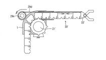
- FIG. 6 is a partial cross-sectional view showing an enlarged cross section of a region surrounded by a broken line in FIG.
- the moving means 21 fixes a block body 22 to another block body 22 while arranging the other block bodies 22 in a uniaxial direction, and directs the rigid block body group 20 from the opening 10b ′ to the outside.
- the rigid section can be shortened by returning the block body group 20 extended or extended outside to the inside of the second support portion 10 b and removing one block body 22 from the block body group 20.
- the length of the rigid section that is, the arm length can be varied, and in other words, the linear motion expansion / contraction joint J3 can be expanded and contracted. Details of the telescopic mechanism will be described next.
- the moving means 21 includes a worm gear reducer 23 in which a rack gear-like lower surface uneven structure 22c of the block body 22 and a worm gear 23a are combined, and a motor for driving the worm gear 23a. 24 is provided.
- the spur gear 23b shown in FIG. 6 is configured to rotate the worm gear 23a by slightly increasing the rotational force of the motor 24.
- the thrust generation direction of the worm gear 23a is the same as the direction of the rotation shaft 23a 'of the worm gear 23a, as shown in FIG. 6, so that the rotation shaft 23a' of the worm gear 23a is in the rigid direction of the block group 20. It arrange
- the rack gear-like lower surface uneven structure 22c of the block body 22 meshes with the worm gear 23a, a mechanism is realized in which the block body 22 moves along the thrust generation direction of the worm gear 23a.
- the rotating shaft of the motor 24 is also in the rigid direction of the block body group 20, it is easy to store a large drive motor in a compact manner without protruding from the side surface of the arm.
- the block body 22 receives the thrust of the worm gear 23a and is fixed to each other inside the second support portion 10b, the fixed block body 22 (block body group 20) is pushed by another block body 22 continuing from the rear. Then, when it is pushed out through the opening 10b ', the linear motion expansion joint J3 is extended.
- the stiff block body group is drawn into the second support portion 10b, and the block bodies 22 are separated in the order in which the worm gear 23a is drawn, and the linear motion expansion joint J3 contracts. Is realized.
- the block bodies 22 deviating from the rigid section are in a series, the mutual connection is movable (flexible section). In the present embodiment, as shown in FIGS. 3 and 4, the block body group in the flexible section is accommodated in a column along the central axis of the support 1. The above is the extension mechanism of the linear motion extension joint J3.
- the arm portion 2 includes two long ropes 25 for movably connecting all the block bodies 22 in series, and the block body 22 as shown in FIGS.
- the toothed belt 26 meshes with the upper surface uneven structure 22b of the block group 20 in a state where the blocks are fixed and rigid.
- the rope 25 seems to generate a slight tension in a state where the block bodies 22 are fixed and arranged in a uniaxial direction so that backlash (slack) does not occur at the connecting portion between the block bodies 22 in the rigid section. It is stretched on the lower surface of the block body group.
- the rope 25 is fixed to each block body 22 using a metal fitting 25a shown in FIG.
- the toothed belt 26 is provided with a concavo-convex shape 26 a so as to mesh with the top concavo-convex structure 22 b of the block body 22, and by meshing with the concavo-convex structure of the adjacent block body 22, between the adjacent block bodies 22. Can be fixed.
- the meshed toothed belt 26 may be peeled off from the block body group in series. No matter what external force is applied to the rigid block body group, the force acting on the toothed belt 26 is only the tensile force in the longitudinal direction, so that there is no possibility that the middle portion will be peeled off.
- the position where the toothed belt 26 can be applied or removed is only at the end of the rigid section.
- the operation of applying or removing the toothed belt 26 is very simple. As shown in FIG. 6, an upper guide roller 27 for performing the former operation and a scraper 28 for performing the latter operation are installed, and the block body group. This can be realized simply by sliding 20 in the connecting direction.
- toothed belt an off-the-shelf toothed belt (timing belt) is used as the toothed belt 26, it has high strength to withstand high loads, the pitch distance between the teeth is made with high accuracy, and is inexpensive. This is preferable.
- the hand unit 3 is disposed at the tip of the arm unit 2. As shown in FIG. 8, the hand unit 3 includes a fourth rotary joint J4, a fifth rotary joint J5, a sixth rotary joint J6, a seventh rotary joint J7, a first finger 30, and a second finger 31. And have.
- the arm of the arm portion can be expanded and contracted without using a bending joint. Therefore, it is possible to avoid pinching between the arms due to rotation of the bending joint provided in the middle of the arm portion.
- This is very significant as a welfare robot arm that assists work in place of human hands in daily life.
- the robot arm of this embodiment is arranged as a welfare robot arm on a wheelchair or bedside, the arm can be expanded and contracted only by linear motion expansion and contraction, so that a bending joint is provided in the middle of the arm part. In comparison with this, the range that blocks the user's view is small, and the user's visual discomfort can be reduced.
- the support body 1 extends in the vertical direction from the installation surface G shown in FIG. 8, but the present invention is not limited to this, as long as it maintains a predetermined angle. .
- the rope 25 is used to make the block bodies 22 into a series.
- the rope 25 has an auxiliary configuration, and instead of the rope 25, a hinge that connects adjacent block bodies is used. May be.
- the toothed belt 26 is used.
- this is also an auxiliary configuration, and a rigid section can be realized without the toothed belt 26.
- the following modification (2) is the case.
- the two-finger hand 32 is used as the hand unit 3, but the present invention is not limited to this, and a hand having three or more finger units may be used. Further, the present invention is not limited to the configuration having the finger part, and any kind of structure that is desired to be arranged at a desired position / posture using the arm part can be connected to the tip of the arm part instead of the hand part 3. For example, a device having an imaging function can be used as the hand unit 3.
- the present embodiment is merely an example of the present invention, and the present invention is not limited to the scope described in the present embodiment, and is within the scope described in the claims. Even if various changes and substitutions are made in the above, they are included in the scope of the present invention. For example, the configuration described in the following modification may be used.
- FIG. 9 is a side view showing a modification of the block group.
- FIG. 9 shows a block body group 20 ′ of the present modification as viewed from the same direction as the block body group 20 of FIG.
- each block body 22 ′ of the block body group 20 ′ is provided with an inter-block fixing latch (latch) mechanism 29 a, and further, an adjacent block body 22 ′ is fixed between blocks.
- a recess 29b is also provided that is configured so that the tip of the latch mechanism 29a can be fitted.
- each block body 22' is movablely connected.
- An inter-block movable coupling mechanism 29c configured to be able to be provided is provided, and these are arranged in series by coupling them adjacent to each other.
- the block bodies 22 ′ arranged in series are rigidly arranged in series when the inter-block fixing latch mechanism 29 a and the recess 29 b are engaged (the rigid section in FIG. 9).
- the inter-block fixing latch mechanism 29a and the concave portion 29b are not engaged, although they are connected by the inter-block movable connecting mechanism 29c, they are not rigid and have flexibility (see FIG. 9 flexible sections).
- FIG. 10 shows a configuration when the block group 20 ′ is connected to the support 1.
- the block body group 20 ′ is defined by the guide mechanism 41 in the protruding direction of the rigid section.
- the above-described guide mechanism may be further added to have a configuration as shown in FIG. In FIG. 11, an additional guide mechanism 42 is provided.
- this additional guide mechanism 42 the internal passage through which the block body group passes is bent, and there is a region that defines the block body group 20 'in the uniaxial direction at both ends of the passage.
- the block body group 20 ′ is in series from the support body 1 to one end of the additional guide mechanism 42, and the inter-block fixing latch mechanism 29 a and the concave portion 29 b between the block bodies 22 ′ are inside (the center part) of the additional guide mechanism 42.
- the latch mechanism for inter-block fixing that has been removed in the region defined in the uniaxial direction of the other end of the additional guide mechanism 42 when it is bent along the bent shape of the additional guide mechanism 42. 29a and the recessed part 29b may be recombined, and the structure which becomes rigid and becomes a series may be sufficient.
- FIG. 12 shows an example of the storage form of the block body 22 'in the flexible section.
- the storage form of the block body 22 ′ of the flexible section stored inside the support body 1 is a spiral type.
- the storage form is not limited to the vertical form of the above-described embodiment, and can be compactly collected in a desired place.
- FIG. 13 shows a drive mechanism using a recess provided on the lower surface of the block body 22 ′.
- FIG. 14 is a diagram showing another modification.
- the configuration of this modification includes a block body group 20 ′ of the arm portion 2 and a drive gear 21 ′ that fits into a recess 22c ′ provided on the lower surface of the block body 22 ′ of the block body group 20 ′.
- a tension rope 29d is stretched from the upper surface of the block body 22 'at the tip close to the hand portion 3 along the upper surface of each block body 22' of the block body group 20 'arranged in series.
- this configuration includes a rope take-up drum 29e for taking up the tension rope 29d, and tension is generated in the direction from the block body 22 'at the tip to the rope take-up drum 29e.
- the pushing force by the drive gear 21 ' is generated in the opposite direction.
- the stiffening force is applied to the block bodies 22 ′ of the block body group 20 ′ arranged in series in the direction indicated by the arrows in FIG. 14 to form a stiff section.
- FIG. 15 shows still another modified example.
- the block bodies 22 ′ are separated from each other by using the gravity of the block body 22 ′ without providing the rope winding drum 29 e in FIG. 15.
- a stiffening force is applied in the direction indicated by the arrow, and a stiffening section is formed.
- the robot arm according to the present invention includes an installation unit fixed to a desk or a floor, a support connected via a first rotary joint that can rotate with respect to the installation unit, and the support with respect to the support unit.
- a uniaxial rod-shaped arm portion connected via a second rotary joint that can rotate in a direction orthogonal to the first rotary joint, and an end effector provided at the other end of the arm portion;
- the arm portion is a linear motion expansion / contraction mechanism that can be expanded and contracted to have a desired arm length, and is provided in advance for constructing a linear motion expansion / contraction mechanism that is prepared in advance so that the necessary maximum arm length can be constructed.
- a portion of the structure that exceeds the desired arm length is separated from the arm portion, and is stored in a space that is off the central axis of the arm portion along the extending direction of the arm portion.
- FIGS. 1 to 24 An embodiment of a robot arm according to the present invention will be described with reference to FIGS. 1 to 24.
- the structure of the robot arm is the same as that already described in [Embodiment 1]. Therefore, in the present embodiment, among the contents related to the robot arm of the present embodiment having the above-described features, only the contents not described in [Embodiment 1] are described.
- the robot arm 40 includes a first rotary joint J1, a second rotary joint J2, a third linear motion telescopic joint J3, a fourth rotary joint J4, a fifth rotary joint J5, It has 6 rotation joint J6 and 7th rotation joint J7, and has 7 degrees of freedom as a whole.
- the robot arm 40 includes a support body 1, an arm unit 2, and a hand unit 3 (gripping unit).
- the arm unit 2 forms an arm having a desired arm length.
- the third linear motion expansion / contraction joint J3 has a length exceeding a desired arm length in the third linear motion expansion / contraction joint J3, and an axis different from the central axis of the arm along the extension direction of the arm.
- a bending joint having a rotation axis in a direction perpendicular to the central axis of the arm provided in the arm portion, and extending and contracting the third linear motion expansion / contraction joint J3. It is configured to be realized without using a link.
- the support body 1 includes the two first support portions 10a and the second support portion 10b, the first rotary joint J1, and the second rotary joint J2.
- the first rotary joint J1 is disposed between the first support portion 10a and the second support portion 10b, and the central axis of the support body 1 (the central axes of the first support portion 10a and the second support portion 10b). ) As a torsional joint link having a rotation axis centered on. When the first rotary joint J1 rotates, as shown in FIGS. 17 and 18, the second support portion 10b, the arm portion 2, and the hand portion 3 rotate about the rotation axis.
- the second rotary joint J ⁇ b> 2 is located at the arm portion side end of the second support portion 10 b and has a rotation axis orthogonal to the axis of the support 1. It is configured as a bending joint.
- the second rotary joint J2 rotates, the arm part 2 and the hand part 3 rotate around the rotation axis of the second rotary joint J2 with respect to the support 1, as shown in FIGS.
- the second rotary joint J2 is configured to have an angle that does not cause a thing around the robot arm 40 to be firmly sandwiched between the support 1 and the link portion 2.
- the angle between the support 1 and the link portion 2 is controlled so as not to be less than 40 °, preferably less than 50 °, more preferably less than 60 °. Thereby, it is possible to remarkably avoid the risk of the above-described pinching between the support 1 and the link portion 2.
- the arm portion 2 keeps the third linear motion expansion joint J3 protruding in the uniaxial direction from the opening portion 10b ′ provided in the second support portion 10b toward the outside, and the second rotary joint J2 described above. Can be turned around. The state is shown in FIG.
- the hand portion 3 is disposed at the tip of the arm portion 2.
- the hand unit 3 includes a fourth rotary joint J4, a fifth rotary joint J5, a sixth rotary joint J6, a seventh rotary joint J7, a first finger 30, and a second finger 31. And have.
- the fourth rotation joint J4 is a torsion joint link having a rotation axis centered on the central axis of the arm portion (hereinafter sometimes referred to as an arm axis) along the expansion / contraction direction of the arm portion 2.
- an arm axis the central axis of the arm portion
- the fifth rotation joint J5 is a bending joint link having a rotation axis orthogonal to the arm axis.
- the fifth rotation joint J5 rotates, as shown in FIG. 22, the two-finger hand 32 from the fifth rotation joint J5 to the tip rotates about the rotation axis.
- the sixth rotation joint J6 is a bending joint link having a rotation axis orthogonal to both the arm axis and the fifth rotation joint J5.
- the sixth rotation joint J6 rotates, the first finger 30 rotates about the rotation axis as shown in FIG.
- the seventh rotation joint J7 is also a bending joint link having a rotation axis orthogonal to both the arm axis and the fifth rotation joint J5.
- the seventh rotation joint J7 rotates, the second finger 31 rotates about the rotation axis as shown in FIG.
- the two-finger hand 32 holds something. If the sixth rotary joint J6 and the seventh rotary joint J7 are rotated in opposite directions so that the tips of the first finger 30 and the second finger 31 approach each other, the two-finger hand 32 holds something. If the sixth rotary joint J6 and the seventh rotary joint J7 are rotated in opposite directions so that the tips of the first finger 30 and the second finger 31 move away from each other, the two-finger hand 32 is moved. The operation is to release the gripped object.
- the arm of the arm portion can be expanded and contracted without using a bending joint link. Therefore, it is possible to avoid pinching between the arms due to the rotation of the bending joint link provided between the arms. This is very significant as a welfare robot arm that assists work in place of human hands in daily life.
- the robot arm according to the present embodiment is arranged as a welfare robot arm on a wheelchair or a bedside, the arm can be expanded and contracted only by linear expansion and contraction. Therefore, a bending joint link is provided between the arm and the arm.
- the range that blocks the user's field of view can be minimized, and the arm's expansion and contraction motion in front of the eyes is simple and small, reducing the user's visual discomfort. Is possible.
- the hand unit 3 performs an operation of grasping or releasing something held by the two-finger hand 32 by interlocking the sixth rotation joint J6 and the seventh rotation joint J7.
- the present invention is not limited to this.
- Another example of the robot arm 40 ′ shown in FIGS. 25 and 26 includes a sixth rotary joint J6, which is a bending joint link having a rotary axis orthogonal to both the arm axis and the fifth rotary joint J5, as a seventh rotary joint. It is provided on the fifth rotation joint J5 side with respect to J7.
- the robot arm 40 ′ includes the seventh rotary joint J 7 for adjusting the distance between the first finger 30 and the second finger 31. If the seventh rotary joint J7 rotates in one direction, the two-finger hand 32 grips something, and if the seventh rotary joint J7 rotates in the direction opposite to the one direction, the two-finger hand 32 The action is to release the gripped object.
- the present embodiment is merely an example of the present invention, and the present invention is not limited to the scope described in the present embodiment, and is within the scope described in the claims. Even if various changes and substitutions are made in the above, they are included in the scope of the present invention.
- the robot arm according to the present invention can significantly reduce the danger of being caught and can reduce the occupied space by configuring the arm portion by a linear motion extension mechanism using a plurality of block bodies. Can do.
- it can be used as an industrial robot arm, and can be suitably used as a welfare device such as an assisting robot or a prosthetic limb that assists in work in place of a human hand in daily life.
Abstract
Description
本発明に係る直動伸縮機構は、複数個のブロック体からなるブロック体群と、或るブロック体に別のブロック体を固定させたり、固定したブロック体同士から一つずつのブロック体を固定解除したりする機能を含有するブロック体の移動手段とを備えており、上記移動手段を用いて、上記ブロック体群から一部もしくは全てのブロック体を直線状かつ硬直に配列させたり、当該硬直な配列の一部もしくは全てを個々のブロック体へ戻るように固定解除したりすることによって、当該硬直な配列が、任意に長さを変えられる直線状のアーム部として構成されることを特徴としている。 [Embodiment 1]
The linear motion expansion / contraction mechanism according to the present invention fixes a block body group composed of a plurality of block bodies and another block body to a certain block body, or fixes one block body from each of the fixed block bodies. Or a block body moving means having a function of releasing, or using the moving means, a part or all of the block bodies are linearly and rigidly arranged from the block body group, or the rigid body The rigid arrangement is configured as a linear arm part whose length can be arbitrarily changed by unfixing a part or all of the simple arrangement so as to return to the individual block body. Yes.
支持体1は、図1に示すように、ロボットアーム40の設置面Gから鉛直方向に伸びた構造を有しており、ロボットアーム40全体を支持している。 [Support]
As shown in FIG. 1, the
図3は、図1中に示した切断線A-A´においてロボットアーム40を切断した矢視断面図である。 [Arm part]
FIG. 3 is a cross-sectional view of the
ハンド部3は、アーム部2の先に配設されている。ハンド部3は、図8に示すように、第4回転関節J4と、第5回転関節J5と、第6回転関節J6と、第7回転関節J7と、第1指30と、第2指31とを有している。 [Hand part]
The
図9は、ブロック体群の変形例を示した側面図である。図9は、図6のブロック体群20と同じ方向から見た状態で、本変形例のブロック体群20´を示している。図9に示すように、ブロック体群20´の各ブロック体22´には、ブロック間固定用ラッチ(掛け金)機構29aが設けられており、更に、隣のブロック体22´のブロック間固定用ラッチ機構29aの先端が勘合するように構成された凹部29bも設けられている。 [Modification (1)]
FIG. 9 is a side view showing a modification of the block group. FIG. 9 shows a
図14は、別の変形例を示した図である。本変形例の構成は、アーム部2のブロック体群20´と、ブロック体群20´のブロック体22´の下面に設けられた凹部22c´に勘合する駆動歯車21´とを備えるとともに、最もハンド部3に近い先端のブロック体22´の上面から、直列に配列しているブロック体群20´の各ブロック体22´の上面に沿って張力ロープ29dを張っている構成である。更に、本構成は、当該張力ロープ29dを巻き取るためのロープ巻き取りドラム29eを備えており、先端のブロック体22´からロープ巻き取りドラム29eの方向へ張力を生じさせている。一方、これとは反対方向に、駆動歯車21´による押し出し力が生じている。これにより、直列に配列しているブロック体群20´の各ブロック体22´には互いに図14中に矢印で示した方向に硬直化力がかかり、硬直区間が形成されることになる。 [Modification (2)]
FIG. 14 is a diagram showing another modification. The configuration of this modification includes a
本発明に係るロボットアームは、机や床などへ固定される設置部と、当該設置部に対して回転できる第1の回転関節を介して接続された支持体と、当該支持体に対して当該第1の回転関節に直交する方向に回転できる第2の回転関節を介して接続された一軸の棒状のアーム部と、当該アーム部の他端に設けられたエンドエフェクタとを有しており、上記アーム部は、所望のアーム長となるように伸縮することができる直動伸縮機構であって、必要最大なアーム長を構築できるように予め用意された、直動伸縮機構を構築するための構造体のうち、上記所望のアーム長を超えた長さの部分をアーム部から分離させ、上記アーム部の伸長方向に沿った当該アーム部の中心軸から外れた空間へ収納するように構成されている直動伸縮機構を有していることを特徴としている。 [Embodiment 2]
The robot arm according to the present invention includes an installation unit fixed to a desk or a floor, a support connected via a first rotary joint that can rotate with respect to the installation unit, and the support with respect to the support unit. A uniaxial rod-shaped arm portion connected via a second rotary joint that can rotate in a direction orthogonal to the first rotary joint, and an end effector provided at the other end of the arm portion; The arm portion is a linear motion expansion / contraction mechanism that can be expanded and contracted to have a desired arm length, and is provided in advance for constructing a linear motion expansion / contraction mechanism that is prepared in advance so that the necessary maximum arm length can be constructed. A portion of the structure that exceeds the desired arm length is separated from the arm portion, and is stored in a space that is off the central axis of the arm portion along the extending direction of the arm portion. Has a linear motion telescopic mechanism It is characterized in that.
上記実施の形態1で説明したように、支持体1は、2つの第1支持部10a及び第2支持部10bと、第1回転関節J1と、第2回転関節J2とを有している。 [Support]
As described in the first embodiment, the
アーム部2に設けられている第3直動伸縮関節J3については、上記実施の形態1において詳述しているので、ここでは説明を省略する。 [Arm part]
Since the third linear motion expansion / contraction joint J3 provided in the
ハンド部3は、上述したように、アーム部2の先に配設されている。ハンド部3は、図8に示すように、第4回転関節J4と、第5回転関節J5と、第6回転関節J6と、第7回転関節J7と、第1指30と、第2指31とを有している。 [Hand part]
As described above, the
2 アーム部(硬直アーム部)
3 ハンド部(把持部、エンドエフェクタ)
10a 第1支持部
10b 第2支持部
10b´ 第2支持部の開口部
20、20´ ブロック体群
21 移動手段
21´ 駆動歯車
22、22´ ブロック体
22a 側面凹凸構造
22b 上面凹凸構造
22c 下面凹凸構造
22c´ 凹部
23 ウオーム歯車減速機
23a ウオーム歯車
23a´ ウオーム歯車の回転軸
23b 平歯車
24 モータ
25 ロープ(ブロック体の間の可動的な連結手段)
25a 金具
26 歯付きベルト(ブロック体の間の固定手段、可撓的なベルト状構造体)
26a 凹凸形状
27 上部ガイドローラ
28 スクレーパ
29a ブロック間固定用ラッチ機構
29b 凹部
29c ブロック間可動連結機構
29d 張力ロープ
29e ロープ巻き取りドラム
30 第1指
31 第2指
32 2指ハンド
40、40´ ロボットアーム
41 ガイド機構
42 追加ガイド機構
G 設置面
J1 第1回転関節
J2 第2回転関節
J3 直動伸縮関節
J4 第4回転関節
J5 第5回転関節
J6 第6回転関節
J7 第7回転関節 1 Support (base)
2 Arm part (rigid arm part)
3 Hand part (grip part, end effector)
10a
25a metal fitting 26 toothed belt (fixing means between block bodies, flexible belt-like structure)
26a
Claims (14)
- 複数個のブロック体からなるブロック体群と、
或るブロック体に別のブロック体を固定させたり、固定したブロック体同士から一つずつのブロック体を固定解除したりする機能を含有するブロック体の移動手段とを備えており、
上記移動手段を用いて、上記ブロック体群から一部もしくは全てのブロック体を直線状かつ硬直に配列させたり、当該硬直な配列の一部もしくは全てを個々のブロック体へ戻るように固定解除したりすることによって、当該硬直な配列が、任意に長さを変えられる直線状の硬直アーム部として構成されることを特徴とする直動伸縮機構。 A block body group composed of a plurality of block bodies;
A block body moving means having a function of fixing another block body to a certain block body or releasing the fixation of each block body from the fixed block bodies;
Using the moving means, a part or all of the block bodies are linearly and rigidly arranged from the block body group, or a part or all of the rigid arrangement is unfixed so as to return to the individual block bodies. The linear arrangement mechanism is characterized in that the rigid arrangement is configured as a linear rigid arm portion whose length can be arbitrarily changed. - 上記硬直アーム部として構成されていない上記ブロック体を、内部に収納することができるように構成された基台が設けられているか、もしくは、当該基台の近傍に当該ブロック体を収納するための空間が設けられていることを特徴とする請求項1に記載の直動伸縮機構。 A base configured to be able to store the block body that is not configured as the rigid arm portion is provided, or for storing the block body in the vicinity of the base The linear motion expansion / contraction mechanism according to claim 1, wherein a space is provided.
- 上記基台は、上記硬直アーム部を回動させて任意の方向へ指向させることができるように構成されていることを特徴とする請求項2に記載の直動伸縮機構。 3. The linear motion expansion / contraction mechanism according to claim 2, wherein the base is configured so that the rigid arm portion can be rotated and directed in an arbitrary direction.
- 上記硬直アーム部として構成されていない上記ブロック体は、隣り合うブロック体同士が可動的に連結されることで可撓的な連続体になっていることを特徴とする請求項1または2に記載の直動伸縮機構。 The said block body which is not comprised as said rigid arm part is a flexible continuous body by the adjacent block bodies being movably connected, The Claim 1 or 2 characterized by the above-mentioned. Linear motion expansion and contraction mechanism.
- 上記硬直アーム部として構成されていない上記ブロック体はそれぞれ独立して、上記基台の上記内部、もしくは上記空間に収納されていることを特徴とする請求項1または2に記載の直動伸縮機構。 The linear motion expansion / contraction mechanism according to claim 1 or 2, wherein the block bodies that are not configured as the rigid arm portions are independently housed in the interior of the base or in the space. .
- 上記硬直アーム部を構成する隣り合う上記ブロック体の間を固定する手段として、配列している個々のブロック体の表面に凹凸形状が設けられ、配列しているブロック体に沿って伸びかつ凹凸形状を有する可撓的なベルト状構造体が備えられ、さらに当該ブロック体の凹凸形状と、当該ベルト状構造体の凹凸形状を互いに咬合させる機構を備えていることを特徴とする請求項3または5に記載の直動伸縮機構。 As a means for fixing between the adjacent block bodies constituting the rigid arm portion, a concavo-convex shape is provided on the surface of each arranged block body, and the concavo-convex shape extends along the arranged block bodies. 6. A flexible belt-like structure having a structure, and a mechanism for engaging the uneven shape of the block body and the uneven shape of the belt-like structure with each other. The linear motion expansion / contraction mechanism described in 1.
- 上記硬直アーム部の一部もしくは全てを個々のブロック体へ戻るように固定解除する手段として、上記互いに咬合している上記ブロック体の凹凸形状と上記ベルト状構造体の凹凸形状の間を剥離させる機構を備えていることを特徴とする請求項6に記載の直動伸縮機構。 As a means for releasing the fixation of a part or all of the rigid arm part so as to return to the individual block body, the uneven shape of the block body and the uneven shape of the belt-like structure are separated from each other. The linear motion expansion / contraction mechanism according to claim 6, further comprising a mechanism.
- 上記ブロック体の移動手段は、歯車と、当該歯車を回転させるアクチュエータとからなる駆動機構を有しており、
個々のブロック体における当該歯車との対向面には、当該歯車の歯と勘合する凹凸形状が設けられ、当該歯車の回転によって配列すべき方向にブロック体が移動させられることを特徴とする請求項1から7までの何れか1項に記載の直動伸縮機構。 The moving means of the block body has a drive mechanism comprising a gear and an actuator that rotates the gear,
The surface of each block body facing the gear is provided with an uneven shape to be fitted with the gear teeth, and the block body is moved in the direction to be arranged by rotation of the gear. 8. The linear motion expansion / contraction mechanism according to any one of 1 to 7. - 請求項1から8までの何れか1項に記載の直動伸縮機構を備えていることを特徴とするロボットアーム。 A robot arm comprising the linear motion expansion / contraction mechanism according to any one of claims 1 to 8.
- 机や床などへ固定される設置部と、当該設置部に対して回転できる第1の回転関節を介して接続された支持体と、
当該支持体に対して当該第1の回転関節に直交する方向に回転できる第2の回転関節を介して接続された一軸の棒状のアーム部と、
当該アーム部の他端に設けられたエンドエフェクタとを有しており、
上記アーム部は、所望のアーム長となるように伸縮することができる直動伸縮機構であって、必要最大なアーム長を構築できるように予め用意された、直動伸縮機構を構築するための構造体のうち、上記所望のアーム長を超えた長さの部分をアーム部から分離させ、上記アーム部の伸長方向に沿った当該アーム部の中心軸から外れた空間へ収納するように構成されている直動伸縮機構を有していることを特徴とするロボットアーム。 An installation part fixed to a desk, a floor, etc., and a support body connected via a first rotary joint capable of rotating with respect to the installation part;
A uniaxial rod-shaped arm connected to the support via a second rotary joint that can rotate in a direction perpendicular to the first rotary joint;
And an end effector provided at the other end of the arm part,
The arm portion is a linear motion expansion / contraction mechanism that can be expanded and contracted to have a desired arm length, and is provided in advance for constructing a linear motion expansion / contraction mechanism that is prepared in advance so that the necessary maximum arm length can be constructed. A portion of the structure that exceeds the desired arm length is separated from the arm portion, and is stored in a space that is off the central axis of the arm portion along the extending direction of the arm portion. A robot arm characterized by having a linear motion expansion / contraction mechanism. - 上記エンドエフェクタは、把持部基部と、把持部掌部と、複数の指部とから構成された把持部であり、
当該把持部基部と上記直動伸縮機構との間には、直動伸縮機構の長手方向に平行な第4の回転関節を備え、
当該把持部基部と当該把持部掌部の間には、当該第4の回転関節に直交する方向の第5の回転関節を備え、
当該把持部掌部とそれぞれの指部の間には、独立に動作できる回転関節を備えることを特徴とする請求項10に記載のロボットアーム。 The end effector is a gripping part composed of a gripping part base, a gripping part palm part, and a plurality of finger parts,
Between the grip part base and the linear motion extension / contraction mechanism, a fourth rotary joint parallel to the longitudinal direction of the linear motion extension / contraction mechanism is provided,
Between the grip part base and the grip part palm, a fifth rotary joint in a direction orthogonal to the fourth rotary joint is provided,
The robot arm according to claim 10, further comprising a rotary joint that can operate independently between the grip portion palm portion and each finger portion. - 上記把持部は、別の構造体を把持することができる複数の指部を有しており、
各上記指部は連動して開閉動作できるように構成されていることを特徴とする請求項10または11に記載のロボットアーム。 The grip part has a plurality of finger parts that can grip another structure,
The robot arm according to claim 10 or 11, wherein each of the finger parts is configured to be able to open and close in conjunction with each other. - 上記エンドエフェクタは、把持部基部と、把持部掌部と、複数の指部とから構成された把持部であり、
当該把持部基部と上記直動伸縮機構との間には、直動伸縮機構の長手方向に平行な第4の回転関節を備え、
当該把持部基部と当該把持部掌部の間には、当該第4の回転関節に直交する方向の第5の回転関節を備え、
当該把持部掌部と当該複数の指部との間には、当該複数の指部を一体的に回動させるための第6の回転関節を備え、
当該複数の指部のうちの1つの指部に対してそのほかの指部が独立に動作して指部同士の間隔を調節するための第7の回転関節を、当該把持部掌部と当該そのほかの指部それぞれとの間に備えることを特徴とする請求項10に記載のロボットアーム。 The end effector is a gripping part composed of a gripping part base, a gripping part palm part, and a plurality of finger parts,
Between the grip part base and the linear motion extension / contraction mechanism, a fourth rotary joint parallel to the longitudinal direction of the linear motion extension / contraction mechanism is provided,
Between the grip part base and the grip part palm, a fifth rotary joint in a direction orthogonal to the fourth rotary joint is provided,
Between the grip part palm part and the plurality of finger parts, a sixth rotary joint for rotating the plurality of finger parts integrally is provided,
A seventh rotary joint for adjusting the interval between the fingers by operating the other fingers independently with respect to one of the plurality of fingers, the palm of the grip and the others The robot arm according to claim 10, wherein the robot arm is provided between each of the fingers. - 上記エンドエフェクタは、撮像部であることを特徴とする請求項10に記載のロボットアーム。 The robot arm according to claim 10, wherein the end effector is an imaging unit.
Priority Applications (5)
| Application Number | Priority Date | Filing Date | Title |
|---|---|---|---|
| EP09833222.4A EP2375104B1 (en) | 2008-12-19 | 2009-12-17 | Linearly moving extendable mechanism and robot arm equipped with linearly moving extendable mechanism |
| US13/140,130 US8925405B2 (en) | 2008-12-19 | 2009-12-17 | Linear-motion telescopic mechanism and robot arm having linear-motion telescopic mechanism |
| CN200980150832.9A CN102257292B (en) | 2008-12-19 | 2009-12-17 | Linearly moving extendable mechanism and robot arm equipped with linearly moving extendable mechanism |
| JP2010542881A JP5317362B2 (en) | 2008-12-19 | 2009-12-17 | Linear motion expansion / contraction mechanism and robot arm equipped with the linear motion expansion / contraction mechanism |
| DK09833222.4T DK2375104T3 (en) | 2008-12-19 | 2009-12-17 | Linear and extendable mechanism and robot arm equipped with a linear and extendable mechanism |
Applications Claiming Priority (4)
| Application Number | Priority Date | Filing Date | Title |
|---|---|---|---|
| JP2008324430 | 2008-12-19 | ||
| JP2008-324430 | 2008-12-19 | ||
| JP2008324408 | 2008-12-19 | ||
| JP2008-324408 | 2008-12-19 |
Publications (1)
| Publication Number | Publication Date |
|---|---|
| WO2010070915A1 true WO2010070915A1 (en) | 2010-06-24 |
Family
ID=42268594
Family Applications (1)
| Application Number | Title | Priority Date | Filing Date |
|---|---|---|---|
| PCT/JP2009/006973 WO2010070915A1 (en) | 2008-12-19 | 2009-12-17 | Linearly moving extendable mechanism and robot arm equipped with linearly moving extendable mechanism |
Country Status (6)
| Country | Link |
|---|---|
| US (1) | US8925405B2 (en) |
| EP (1) | EP2375104B1 (en) |
| JP (1) | JP5317362B2 (en) |
| CN (1) | CN102257292B (en) |
| DK (1) | DK2375104T3 (en) |
| WO (1) | WO2010070915A1 (en) |
Cited By (26)
| Publication number | Priority date | Publication date | Assignee | Title |
|---|---|---|---|---|
| WO2011152265A1 (en) * | 2010-05-31 | 2011-12-08 | 独立行政法人産業技術総合研究所 | Direct acting extensible and retractable arm mechanism, and robot arm provided with direct acting extensible and retractable arm mechanism |
| WO2015139879A1 (en) * | 2014-03-19 | 2015-09-24 | Paul Vahle Gmbh & Co. Kg | Current-collector system having a telescopic arm for cranes, container cranes, ertgs, and conveying devices |
| JP2015213974A (en) * | 2014-05-09 | 2015-12-03 | アマノ株式会社 | Linear-moving expansion device and linear-moving expansion type gate device including the same |
| JP2016078160A (en) * | 2014-10-15 | 2016-05-16 | ライフロボティクス株式会社 | Robot arm mechanism |
| WO2016104806A1 (en) * | 2014-12-27 | 2016-06-30 | ライフロボティクス株式会社 | Robot arm mechanism and linearly moving extendable mechanism |
| WO2016104807A1 (en) * | 2014-12-27 | 2016-06-30 | ライフロボティクス株式会社 | Robot arm mechanism and linearly moving extendable mechanism |
| WO2016117627A1 (en) * | 2015-01-24 | 2016-07-28 | ライフロボティクス株式会社 | Direct-acting extension/retraction mechanism, and robot arm mechanism |
| WO2016117626A1 (en) * | 2015-01-24 | 2016-07-28 | ライフロボティクス株式会社 | Coupling segment, direct-acting extension/retraction mechanism, and robot arm mechanism |
| JP2016168646A (en) * | 2015-03-12 | 2016-09-23 | ライフロボティクス株式会社 | Straight-motion extension and contraction mechanism and robot arm mechanism |
| WO2016181801A1 (en) * | 2015-05-12 | 2016-11-17 | ライフロボティクス株式会社 | Robot system |
| WO2016199703A1 (en) * | 2015-06-08 | 2016-12-15 | ライフロボティクス株式会社 | Robot arm mechanism |
| JP2016209970A (en) * | 2015-05-12 | 2016-12-15 | ライフロボティクス株式会社 | Robot arm mechanism |
| JP2017007021A (en) * | 2015-06-19 | 2017-01-12 | ライフロボティクス株式会社 | Tool for adjusting arm reference position of direct-acting joint |
| WO2017014220A1 (en) * | 2015-07-20 | 2017-01-26 | ライフロボティクス株式会社 | Robot device |
| WO2017043582A1 (en) * | 2015-09-11 | 2017-03-16 | ライフロボティクス株式会社 | Linear extension-retraction mechanism |
| WO2017150319A1 (en) * | 2016-02-29 | 2017-09-08 | ライフロボティクス株式会社 | Direct-acting extension/retraction mechanism, and robot arm mechanism |
| WO2017208872A1 (en) * | 2016-05-31 | 2017-12-07 | ライフロボティクス株式会社 | Linear expansion/contraction mechanism |
| US9994431B2 (en) | 2014-04-11 | 2018-06-12 | Paul Vahle Gmbh & Co. Kg | Positioning area for a route for vertically inserting current collector contacts in the current rails of the route |
| EP3213882A4 (en) * | 2014-10-30 | 2018-08-08 | Life Robotics Inc. | Robot arm mechanism |
| JPWO2017094631A1 (en) * | 2015-11-30 | 2018-10-04 | ライフロボティクス株式会社 | Linear motion expansion / contraction mechanism |
| US10139041B2 (en) | 2014-03-19 | 2018-11-27 | Paul Vahle Gmbh & Co. Kg | Telescopic arm with a push-pull chain drive |
| CN109249407A (en) * | 2018-11-01 | 2019-01-22 | 合肥工业大学 | A kind of hard and soft combination drive spray robot with non-individual body wrist joint |
| CN109404658A (en) * | 2018-12-20 | 2019-03-01 | 南京管科智能科技有限公司 | A kind of Zhui Chi transmission pipe robot |
| CN109822556A (en) * | 2019-04-17 | 2019-05-31 | 桂林电子科技大学信息科技学院 | Industry mechanical arm based on PLC control |
| WO2022009816A1 (en) * | 2020-07-08 | 2022-01-13 | ファナック株式会社 | Linear motion mechanism |
| CN114688404A (en) * | 2020-12-31 | 2022-07-01 | 清华大学 | Goods checking device and method thereof |
Families Citing this family (63)
| Publication number | Priority date | Publication date | Assignee | Title |
|---|---|---|---|---|
| CN101925444B (en) * | 2008-01-22 | 2012-07-04 | 松下电器产业株式会社 | Robot arm |
| CN102588545A (en) * | 2012-03-06 | 2012-07-18 | 王晓晖 | Automatically telescopic translational device |
| FR2991884B1 (en) * | 2012-06-13 | 2015-09-11 | Total Raffinage Marketing | DISTRIBUTION OF SOLID PARTICLES IN A REACTOR |
| CN103231388B (en) * | 2013-05-10 | 2015-06-24 | 南开大学 | Flexible operating arm used for service robot |
| CN104822037B (en) * | 2014-01-30 | 2019-03-08 | 德思来科技有限公司 | Nested type projector with built-in electric cantilever |
| DE102014103164B4 (en) | 2014-03-10 | 2022-05-25 | Baker Hughes Digital Solutions Gmbh | Chain with elastic back strap |
| JP6482136B2 (en) * | 2014-03-14 | 2019-03-13 | ライフロボティクス株式会社 | Telescopic arm mechanism |
| US9314928B2 (en) | 2014-08-21 | 2016-04-19 | Elwha Llc | Systems, devices, and methods including a wheelchair-assist robot |
| US9314929B2 (en) | 2014-08-21 | 2016-04-19 | Elwha Llc | Systems, devices, and methods including a wheelchair-assist robot |
| US10099379B2 (en) * | 2014-08-21 | 2018-10-16 | Elwha Llc | Systems, devices, and methods including a wheelchair-assist robot |
| JP6443875B2 (en) * | 2014-10-24 | 2018-12-26 | ライフロボティクス株式会社 | Robot arm mechanism |
| JP6508704B2 (en) * | 2014-11-29 | 2019-05-08 | ライフロボティクス株式会社 | Robot arm mechanism |
| JP2016117126A (en) * | 2014-12-20 | 2016-06-30 | ライフロボティクス株式会社 | Robot arm mechanism |
| JP2016125588A (en) * | 2014-12-29 | 2016-07-11 | ライフロボティクス株式会社 | Direct-acting expansion mechanism and robot arm mechanism |
| US10881475B2 (en) * | 2015-07-09 | 2021-01-05 | Kawasaki Jukogyo Kabushiki Kaisha | Surgical robot |
| CN106493720B (en) * | 2015-09-06 | 2021-09-14 | 上海科斗电子科技有限公司 | Flexible mechanical skeleton |
| JP1556242S (en) * | 2015-11-24 | 2016-08-15 | ||
| JP1556241S (en) * | 2015-11-24 | 2016-08-15 | ||
| JP1556243S (en) * | 2015-11-24 | 2016-08-15 | ||
| JP1556240S (en) * | 2015-11-24 | 2016-08-15 | ||
| US11331154B2 (en) | 2016-01-07 | 2022-05-17 | Intuitive Surgical Operations, Inc. | Telescoping cannula arm |
| JP6725541B2 (en) * | 2016-01-30 | 2020-07-22 | ライフロボティクス株式会社 | Robot arm mechanism |
| CN108698237B (en) * | 2016-02-29 | 2022-01-04 | 生活机器人学股份有限公司 | Direct-acting telescopic mechanism and mechanical arm mechanism with same |
| WO2017150318A1 (en) * | 2016-02-29 | 2017-09-08 | ライフロボティクス株式会社 | Robot arm mechanism, and direct-acting extension/retraction mechanism |
| CN105605170B (en) * | 2016-03-22 | 2018-11-13 | 林穗强 | chain-type rack push-pull rod |
| WO2017170303A1 (en) | 2016-03-29 | 2017-10-05 | ライフロボティクス株式会社 | Robot arm mechanism and rotary joint device |
| JP6740339B2 (en) * | 2016-03-29 | 2020-08-12 | ライフロボティクス株式会社 | Linear motion telescopic mechanism and robot arm mechanism |
| DE112017001609T5 (en) * | 2016-03-29 | 2018-12-20 | Life Robotics Inc. | Linear extension and retraction mechanism and robot arm mechanism. |
| DE112017001742T5 (en) * | 2016-03-29 | 2018-12-27 | Life Robotics Inc. | Torsion joint mechanism, robot arm mechanism and cantilevered rotating mechanism |
| CN105729223B (en) * | 2016-04-30 | 2018-07-03 | 桐乡弗格莱纺织有限公司 | A kind of workpiece feeding device |
| JP6659846B2 (en) * | 2016-07-30 | 2020-03-04 | ライフロボティクス株式会社 | Robot arm mechanism |
| JP2018047515A (en) * | 2016-09-20 | 2018-03-29 | 株式会社東芝 | Robot hand device and transportation device using robot hand device |
| CN106426279A (en) * | 2016-11-15 | 2017-02-22 | 北京工业大学 | Telescopic mechanical arm |
| EP3342626A1 (en) * | 2016-12-27 | 2018-07-04 | Mobimar Oy | Charging connection device and charging arrangement |
| CN107696063A (en) * | 2017-10-10 | 2018-02-16 | 无锡迪奥机械有限公司 | Arm expanding device |
| KR102399871B1 (en) * | 2017-11-08 | 2022-05-20 | 삼성전자 주식회사 | Robot arm extension apparatus and robot including the same |
| CN108302198A (en) * | 2018-03-30 | 2018-07-20 | 法可赛(太仓)汽车配件有限公司 | Shift driving device |
| TW201946354A (en) * | 2018-04-26 | 2019-12-01 | 和碩聯合科技股份有限公司 | Telescopic adjuster |
| US10935106B2 (en) | 2018-06-14 | 2021-03-02 | Serapid, Inc. | Block chain with monolithic links |
| CN108890656B (en) * | 2018-07-11 | 2020-07-03 | 北京工业大学 | Telescopic service robot that contains friction wheel drive |
| US11553973B2 (en) * | 2019-07-29 | 2023-01-17 | Verb Surgical Inc. | Robotic arm having an extendable prismatic link |
| CA3155598A1 (en) * | 2019-10-02 | 2021-04-08 | Farm Improvements Limited | Sprayer with articulated arm and sensor system |
| JP7359638B2 (en) * | 2019-10-23 | 2023-10-11 | ファナック株式会社 | Direct-acting telescopic mechanism |
| JP7359648B2 (en) * | 2019-10-31 | 2023-10-11 | ファナック株式会社 | robot equipment |
| JP2023504268A (en) * | 2019-12-06 | 2023-02-02 | ハロー ロボット インコーポレイテッド | ACTIVATION SYSTEM AND METHOD OF ACTIVATED ACTIVATION SYSTEM |
| WO2021113726A1 (en) | 2019-12-06 | 2021-06-10 | Hello Robot | Mobile manipulation system |
| US11371437B2 (en) * | 2020-03-10 | 2022-06-28 | Oliver Crispin Robotics Limited | Insertion tool |
| CN111823269A (en) * | 2020-06-23 | 2020-10-27 | 北京航空航天大学 | Measuring tape zipper type telescopic mechanical arm and design method thereof |
| US20220094145A1 (en) * | 2020-09-24 | 2022-03-24 | Honeywell International Inc. | Adjustable insulating device |
| CN113771011B (en) * | 2020-10-22 | 2023-05-30 | 桂林电子科技大学 | A end subassembly for robotic mechanism |
| CN112720417B (en) * | 2020-12-24 | 2022-11-04 | 广州大学 | Novel modular soft robot and activity control method thereof |
| WO2022177499A1 (en) * | 2021-02-17 | 2022-08-25 | Invivo Medical Pte. Ltd. | Simulation and training apparatus |
| DE102021113892A1 (en) * | 2021-05-28 | 2022-12-01 | Chiron Group Se | Combined transfer and storage device and system for machining |
| US11620868B2 (en) | 2021-07-22 | 2023-04-04 | Trinity Axis Inc. | Techniques to dispense an item and release a jammed item from a dispensing system |
| CN113459127B (en) * | 2021-07-31 | 2022-03-18 | 西南科技大学 | Self-growing soft and hard integrated robot and application thereof |
| US11787069B2 (en) | 2021-11-01 | 2023-10-17 | Oliver Crispin Robotics Limited | Insertion tool with flexible spine |
| US11894631B2 (en) | 2021-11-24 | 2024-02-06 | Caterpillar Inc. | Concentric conductor |
| US11881653B2 (en) | 2021-11-24 | 2024-01-23 | Caterpillar Inc. | System and method for positioning a conductive rod powering a work machine |
| US11688973B2 (en) | 2021-11-24 | 2023-06-27 | Caterpillar Inc. | Connector assembly for conductor rod having multiple degrees of freedom |
| US11923632B2 (en) | 2021-11-24 | 2024-03-05 | Caterpillar Inc. | Terminal assembly for conductor rod having multiple degrees of freedom |
| US11855379B2 (en) | 2021-11-24 | 2023-12-26 | Caterpillar Inc. | Slidable nested conductors |
| US11859370B2 (en) | 2021-11-24 | 2024-01-02 | Caterpillar Inc. | Multi-tiered interface between conductor rod and work machine |
| CN116021551B (en) * | 2023-03-31 | 2023-06-02 | 成都思越智能装备股份有限公司 | Connecting rod type mechanical arm |
Citations (9)
| Publication number | Priority date | Publication date | Assignee | Title |
|---|---|---|---|---|
| JPS6145168A (en) | 1984-08-10 | 1986-03-05 | Hitachi Ltd | Direct-acting actuator |
| JPS6384882A (en) | 1986-09-29 | 1988-04-15 | トヨタ自動車株式会社 | Robot |
| JPH0193733U (en) * | 1987-12-15 | 1989-06-20 | ||
| JPH0429660A (en) * | 1990-05-25 | 1992-01-31 | Asahi Okuma Ind Co Ltd | Reciprocation moving device |
| JPH0639758A (en) | 1992-07-23 | 1994-02-15 | Matsushita Electric Ind Co Ltd | Robot arm |
| JPH07116986A (en) * | 1993-10-22 | 1995-05-09 | Mitsubishi Electric Corp | Industrial robot |
| JPH07164369A (en) * | 1993-12-15 | 1995-06-27 | Mitsubishi Motors Corp | Expansion arm mechanism |
| JPH07194610A (en) * | 1993-12-28 | 1995-08-01 | Olympus Optical Co Ltd | Medical tool |
| JP2007290068A (en) | 2006-04-24 | 2007-11-08 | Atsuo Takanishi | Straight move link device, robot using the same, and bipedal walking robot |
Family Cites Families (21)
| Publication number | Priority date | Publication date | Assignee | Title |
|---|---|---|---|---|
| US4473365A (en) * | 1980-11-26 | 1984-09-25 | Lapeyre James M | Detachable link chain |
| FR2512909B1 (en) * | 1981-09-15 | 1987-02-20 | Renault | RECTILINEAR PULLEY AND BELT TRANSMISSION MECHANISM |
| US4588347A (en) * | 1981-10-02 | 1986-05-13 | Coles Cranes Limited | Telescopic booms |
| JP2602815B2 (en) * | 1986-08-08 | 1997-04-23 | 株式会社東芝 | Joint device |
| JPH0193733A (en) | 1987-10-06 | 1989-04-12 | Fuji Photo Film Co Ltd | Ultrahigh contrast negative type silver halide photographic sensitive material |
| JPH03351A (en) * | 1989-03-27 | 1991-01-07 | Okuma Mach Works Ltd | Transmission mechanism |
| CN2060469U (en) * | 1989-11-22 | 1990-08-15 | 陆士春 | Straight pull-rod type compressed buffer automatic door-closing apparatus |
| FR2786476B1 (en) * | 1998-11-30 | 2001-02-23 | Serapid France | LOAD LIFT COLUMN |
| US6394998B1 (en) * | 1999-01-22 | 2002-05-28 | Intuitive Surgical, Inc. | Surgical tools for use in minimally invasive telesurgical applications |
| FR2826422B1 (en) * | 2001-06-26 | 2003-11-14 | Serapid France | LINEAR BELT ACTUATOR |
| ES2287505T3 (en) * | 2002-05-03 | 2007-12-16 | Clark Equipment Company | CARRIER OF REMOVABLE HYDRAULIC HOSE. |
| EP1701825A4 (en) * | 2003-12-30 | 2007-04-18 | Strider Labs Inc | Robotic hand with extendable palm |
| US20060156851A1 (en) * | 2004-12-02 | 2006-07-20 | Jacobsen Stephen C | Mechanical serpentine device |
| US7621078B2 (en) * | 2005-01-20 | 2009-11-24 | Drs Sustainment Systems, Inc. | Telescoping mast having variable height locking and a chain erection mechanism with a cable management system |
| DE102006025844B3 (en) * | 2005-10-13 | 2007-11-22 | Thyssenkrupp Drauz Nothelfer Gmbh | Handling system for form-related components, in particular body parts for motor vehicles |
| JP5042738B2 (en) * | 2007-07-30 | 2012-10-03 | テルモ株式会社 | Working mechanism and cleaning method of medical manipulator |
| US8176808B2 (en) * | 2007-09-13 | 2012-05-15 | Foster-Miller, Inc. | Robot arm assembly |
| JP2009119565A (en) * | 2007-11-15 | 2009-06-04 | Denso Wave Inc | Robot |
| KR101336377B1 (en) * | 2008-04-18 | 2013-12-04 | 포티메딕스 서지컬 비.브이. | An instrument for endoscopic applications or the like |
| US20110022078A1 (en) * | 2009-07-23 | 2011-01-27 | Cameron Dale Hinman | Articulating mechanism |
| WO2013082310A1 (en) * | 2011-12-02 | 2013-06-06 | Barosense, Inc. | Positioning device and articulation assembly for remote positioning of a tool |
-
2009
- 2009-12-17 WO PCT/JP2009/006973 patent/WO2010070915A1/en active Application Filing
- 2009-12-17 CN CN200980150832.9A patent/CN102257292B/en not_active Withdrawn - After Issue
- 2009-12-17 EP EP09833222.4A patent/EP2375104B1/en active Active
- 2009-12-17 JP JP2010542881A patent/JP5317362B2/en active Active
- 2009-12-17 US US13/140,130 patent/US8925405B2/en active Active
- 2009-12-17 DK DK09833222.4T patent/DK2375104T3/en active
Patent Citations (9)
| Publication number | Priority date | Publication date | Assignee | Title |
|---|---|---|---|---|
| JPS6145168A (en) | 1984-08-10 | 1986-03-05 | Hitachi Ltd | Direct-acting actuator |
| JPS6384882A (en) | 1986-09-29 | 1988-04-15 | トヨタ自動車株式会社 | Robot |
| JPH0193733U (en) * | 1987-12-15 | 1989-06-20 | ||
| JPH0429660A (en) * | 1990-05-25 | 1992-01-31 | Asahi Okuma Ind Co Ltd | Reciprocation moving device |
| JPH0639758A (en) | 1992-07-23 | 1994-02-15 | Matsushita Electric Ind Co Ltd | Robot arm |
| JPH07116986A (en) * | 1993-10-22 | 1995-05-09 | Mitsubishi Electric Corp | Industrial robot |
| JPH07164369A (en) * | 1993-12-15 | 1995-06-27 | Mitsubishi Motors Corp | Expansion arm mechanism |
| JPH07194610A (en) * | 1993-12-28 | 1995-08-01 | Olympus Optical Co Ltd | Medical tool |
| JP2007290068A (en) | 2006-04-24 | 2007-11-08 | Atsuo Takanishi | Straight move link device, robot using the same, and bipedal walking robot |
Non-Patent Citations (1)
| Title |
|---|
| See also references of EP2375104A4 * |
Cited By (37)
| Publication number | Priority date | Publication date | Assignee | Title |
|---|---|---|---|---|
| WO2011152265A1 (en) * | 2010-05-31 | 2011-12-08 | 独立行政法人産業技術総合研究所 | Direct acting extensible and retractable arm mechanism, and robot arm provided with direct acting extensible and retractable arm mechanism |
| JP5435679B2 (en) * | 2010-05-31 | 2014-03-05 | 独立行政法人産業技術総合研究所 | Linear motion telescopic arm mechanism and robot arm equipped with the linear motion telescopic arm mechanism |
| US9248576B2 (en) | 2010-05-31 | 2016-02-02 | National Institute Of Advanced Industrial Science And Technology | Direct acting extensible and retractable arm mechanism, and robot arm provided with direct acting extensible and retractable arm mechanism |
| WO2015139879A1 (en) * | 2014-03-19 | 2015-09-24 | Paul Vahle Gmbh & Co. Kg | Current-collector system having a telescopic arm for cranes, container cranes, ertgs, and conveying devices |
| US10137785B2 (en) | 2014-03-19 | 2018-11-27 | Paul Vahle Gmbh & Co. Kg | Current collector system having telescopic arm for cranes, container cranes, ERTGs, and conveying devices |
| US10139041B2 (en) | 2014-03-19 | 2018-11-27 | Paul Vahle Gmbh & Co. Kg | Telescopic arm with a push-pull chain drive |
| US9994431B2 (en) | 2014-04-11 | 2018-06-12 | Paul Vahle Gmbh & Co. Kg | Positioning area for a route for vertically inserting current collector contacts in the current rails of the route |
| JP2015213974A (en) * | 2014-05-09 | 2015-12-03 | アマノ株式会社 | Linear-moving expansion device and linear-moving expansion type gate device including the same |
| JP2016078160A (en) * | 2014-10-15 | 2016-05-16 | ライフロボティクス株式会社 | Robot arm mechanism |
| EP3213882A4 (en) * | 2014-10-30 | 2018-08-08 | Life Robotics Inc. | Robot arm mechanism |
| US10960537B2 (en) | 2014-10-30 | 2021-03-30 | Life Robotics Inc. | Robot arm mechanism |
| WO2016104806A1 (en) * | 2014-12-27 | 2016-06-30 | ライフロボティクス株式会社 | Robot arm mechanism and linearly moving extendable mechanism |
| WO2016104807A1 (en) * | 2014-12-27 | 2016-06-30 | ライフロボティクス株式会社 | Robot arm mechanism and linearly moving extendable mechanism |
| EP3238892A4 (en) * | 2014-12-27 | 2018-08-22 | Life Robotics Inc. | Robot arm mechanism and linearly moving extendable mechanism |
| WO2016117627A1 (en) * | 2015-01-24 | 2016-07-28 | ライフロボティクス株式会社 | Direct-acting extension/retraction mechanism, and robot arm mechanism |
| WO2016117626A1 (en) * | 2015-01-24 | 2016-07-28 | ライフロボティクス株式会社 | Coupling segment, direct-acting extension/retraction mechanism, and robot arm mechanism |
| JP2016168646A (en) * | 2015-03-12 | 2016-09-23 | ライフロボティクス株式会社 | Straight-motion extension and contraction mechanism and robot arm mechanism |
| JP2016209970A (en) * | 2015-05-12 | 2016-12-15 | ライフロボティクス株式会社 | Robot arm mechanism |
| WO2016181801A1 (en) * | 2015-05-12 | 2016-11-17 | ライフロボティクス株式会社 | Robot system |
| JP2017001124A (en) * | 2015-06-08 | 2017-01-05 | ライフロボティクス株式会社 | Robot arm mechanism |
| WO2016199703A1 (en) * | 2015-06-08 | 2016-12-15 | ライフロボティクス株式会社 | Robot arm mechanism |
| JP2017007021A (en) * | 2015-06-19 | 2017-01-12 | ライフロボティクス株式会社 | Tool for adjusting arm reference position of direct-acting joint |
| WO2017014220A1 (en) * | 2015-07-20 | 2017-01-26 | ライフロボティクス株式会社 | Robot device |
| JPWO2017043582A1 (en) * | 2015-09-11 | 2018-07-12 | ライフロボティクス株式会社 | Linear motion expansion / contraction mechanism |
| WO2017043582A1 (en) * | 2015-09-11 | 2017-03-16 | ライフロボティクス株式会社 | Linear extension-retraction mechanism |
| JPWO2017094631A1 (en) * | 2015-11-30 | 2018-10-04 | ライフロボティクス株式会社 | Linear motion expansion / contraction mechanism |
| WO2017150319A1 (en) * | 2016-02-29 | 2017-09-08 | ライフロボティクス株式会社 | Direct-acting extension/retraction mechanism, and robot arm mechanism |
| JPWO2017150319A1 (en) * | 2016-02-29 | 2018-12-27 | ライフロボティクス株式会社 | Linear motion expansion / contraction mechanism and robot arm mechanism |
| JPWO2017208872A1 (en) * | 2016-05-31 | 2019-03-28 | ライフロボティクス株式会社 | Linear motion expansion / contraction mechanism |
| WO2017208872A1 (en) * | 2016-05-31 | 2017-12-07 | ライフロボティクス株式会社 | Linear expansion/contraction mechanism |
| US10968980B2 (en) | 2016-05-31 | 2021-04-06 | Life Robotics Inc. | Linear extension and retraction mechanism |
| CN109249407A (en) * | 2018-11-01 | 2019-01-22 | 合肥工业大学 | A kind of hard and soft combination drive spray robot with non-individual body wrist joint |
| CN109404658A (en) * | 2018-12-20 | 2019-03-01 | 南京管科智能科技有限公司 | A kind of Zhui Chi transmission pipe robot |
| CN109404658B (en) * | 2018-12-20 | 2023-08-15 | 南京管科智能科技有限公司 | Bevel gear transmission pipeline robot |
| CN109822556A (en) * | 2019-04-17 | 2019-05-31 | 桂林电子科技大学信息科技学院 | Industry mechanical arm based on PLC control |
| WO2022009816A1 (en) * | 2020-07-08 | 2022-01-13 | ファナック株式会社 | Linear motion mechanism |
| CN114688404A (en) * | 2020-12-31 | 2022-07-01 | 清华大学 | Goods checking device and method thereof |
Also Published As
| Publication number | Publication date |
|---|---|
| JP5317362B2 (en) | 2013-10-16 |
| CN102257292A (en) | 2011-11-23 |
| US20120024091A1 (en) | 2012-02-02 |
| DK2375104T3 (en) | 2013-05-13 |
| US8925405B2 (en) | 2015-01-06 |
| EP2375104B1 (en) | 2013-04-24 |
| EP2375104A1 (en) | 2011-10-12 |
| CN102257292B (en) | 2014-01-08 |
| JPWO2010070915A1 (en) | 2012-05-24 |
| EP2375104A4 (en) | 2012-05-30 |
Similar Documents
| Publication | Publication Date | Title |
|---|---|---|
| JP5317362B2 (en) | Linear motion expansion / contraction mechanism and robot arm equipped with the linear motion expansion / contraction mechanism | |
| JP5122134B2 (en) | Robot hand | |
| JP5435679B2 (en) | Linear motion telescopic arm mechanism and robot arm equipped with the linear motion telescopic arm mechanism | |
| US20230034145A1 (en) | Parallel kinematic mechanisms with decoupled rotational motions | |
| JP5787325B2 (en) | Humanoid electric hand | |
| JP4125513B2 (en) | Humanoid robot arm | |
| RU2427348C2 (en) | Hand prosthesis | |
| US10405936B2 (en) | Parallel kinematic mechanisms with decoupled rotational motions | |
| EP2108339B1 (en) | Functional hand prosthesis mechanism | |
| WO2016117626A1 (en) | Coupling segment, direct-acting extension/retraction mechanism, and robot arm mechanism | |
| ITPI20120049A1 (en) | SELF-CONTENT MULTIFUNCTIONAL HAND PROSTHESIS | |
| WO2017167349A1 (en) | Spherical joint mechanism with a double parallelogram mechanism | |
| WO2016104807A1 (en) | Robot arm mechanism and linearly moving extendable mechanism | |
| JP6016453B2 (en) | Hand Exo Skeleton Device with Three-layer Linked Spring Slide Mechanism | |
| WO2007053795A2 (en) | Converting rotational motion into radial motion | |
| JP2003117873A (en) | Human body type robot hand | |
| JP4365341B2 (en) | Robot hand | |
| US20210068988A1 (en) | Driving Assembly for Moving Body Part | |
| JP2005180566A (en) | Rotary expansion and contraction link mechanism | |
| Su et al. | Design of a lightweight forearm exoskeleton for fine-motion rehabilitation | |
| CN114340519A (en) | Surgical tool, surgical support system, and surgical operation unit | |
| WO2020179814A1 (en) | Liquid pressure medical device and surgical assistance robot | |
| WO2018008254A1 (en) | Extension/retraction mechanism and four-legged robot | |
| Nelson et al. | Design of a modular, partially disposable robot for minimally invasive surgery | |
| KR101867763B1 (en) | Bending stiffness control device for joint device |
Legal Events
| Date | Code | Title | Description |
|---|---|---|---|
| WWE | Wipo information: entry into national phase |
Ref document number: 200980150832.9 Country of ref document: CN |
|
| 121 | Ep: the epo has been informed by wipo that ep was designated in this application |
Ref document number: 09833222 Country of ref document: EP Kind code of ref document: A1 |
|
| ENP | Entry into the national phase |
Ref document number: 2010542881 Country of ref document: JP Kind code of ref document: A |
|
| WWE | Wipo information: entry into national phase |
Ref document number: 13140130 Country of ref document: US |
|
| NENP | Non-entry into the national phase |
Ref country code: DE |
|
| WWE | Wipo information: entry into national phase |
Ref document number: 2009833222 Country of ref document: EP |