JP2017007021A - Tool for adjusting arm reference position of direct-acting joint - Google Patents
Tool for adjusting arm reference position of direct-acting joint Download PDFInfo
- Publication number
- JP2017007021A JP2017007021A JP2015123954A JP2015123954A JP2017007021A JP 2017007021 A JP2017007021 A JP 2017007021A JP 2015123954 A JP2015123954 A JP 2015123954A JP 2015123954 A JP2015123954 A JP 2015123954A JP 2017007021 A JP2017007021 A JP 2017007021A
- Authority
- JP
- Japan
- Prior art keywords
- arm
- jig
- joint
- cover
- plates
- Prior art date
- Legal status (The legal status is an assumption and is not a legal conclusion. Google has not performed a legal analysis and makes no representation as to the accuracy of the status listed.)
- Granted
Links
Images


Landscapes
- Manipulator (AREA)
Abstract
Description
本発明の実施形態は直動関節のアーム基準位置を合わせるための冶具に関する。 Embodiments described herein relate generally to a jig for adjusting an arm reference position of a linear motion joint.
従来より、多関節ロボットアーム機構が産業用ロボットなどさまざまな分野で用いられている。ある種の多関節ロボットアーム機構は、回転関節とともに移動長の比較的長い直動関節を装備している。 Conventionally, articulated robot arm mechanisms have been used in various fields such as industrial robots. Some types of articulated robot arm mechanisms are equipped with a rotary joint and a linear joint with a relatively long movement length.
この移動長の比較的長い直動関節は、従来、手先の前後の移動を担っていた肘関節部を不要とし、容易に特異点を解消することができるので今後非常に有益な構造ではあるが、その長い移動長はアーム部を伸縮性のあるアームカバーで覆う構造を必要としている。 This linear motion joint with a relatively long movement length eliminates the need for the elbow joint, which has traditionally been used to move the front and back of the hand, and can easily eliminate the singularity. The long moving length requires a structure in which the arm portion is covered with a stretchable arm cover.
ところで周知の通り、ロボットアーム機構の出荷時又は設置時にはアーム部の制御上の認識長を実際の伸縮長に整合させる位置合わせ作業が必要とされる。典型的にはアーム部2を最も収縮させ、その位置を動作制御上の原点(直動関節のアーム基準位置)として制御部に認識させ(「原点出し」という)、アーム部の送り出し長を制御している。
As is well known, at the time of shipment or installation of the robot arm mechanism, an alignment operation for matching the control recognition length of the arm unit with the actual extension / contraction length is required. Typically, the
図8は、アーム部を伸縮させる方向に対して垂直方向から見たロボットアーム機構1の外観側面を示す図である。ロボットアーム機構1は、略円筒形状の基部10と、基部10に接続されるアーム部2と、アーム部2の先端に取り付けられる手首部4とを有する。図8は、アーム部2をアームカバーで覆わない場合に最も収縮させた状態を示している。図8に示すように、アーム部2がアームカバーにより覆われていなければ、アーム部は、安定した状態で最も収縮させた位置に位置合わせすることができ、正しく原点出しすることが可能となる。
FIG. 8 is a diagram illustrating an external side view of the robot arm mechanism 1 viewed from a direction perpendicular to the direction in which the arm portion is expanded and contracted. The robot arm mechanism 1 has a substantially
しかし、ロボットアーム機構1は、前述したように、アーム部2が伸縮性のあるアームカバーで覆われた状態で提供される。従って、アーム部2をアームカバーで覆った状態で最も収縮させると、図8に示す位置よりアームカバーを最も圧縮させた厚さ分の手前位置までしか収縮させることができない。図9は、アーム部2をアームカバー6で覆った場合に最も収縮させた状態を示している。なお、図9では、アーム部2が露出されるようにアームカバー6を切欠いて示している。また、図9に示すLb(Short)は、アームカバー6を最も圧縮させた状態における圧縮方向の長さ(以下、収縮長と称する)を示している。
However, the robot arm mechanism 1 is provided in a state where the
図9に示すように、アーム部2をアームカバー6で覆った場合には、アームカバー6の収縮長分の手前位置までしかアーム部2を収縮させることができないため、その位置で原点出しをする必要がある。
As shown in FIG. 9, when the
しかしながら、アームカバー6は、アーム部2の伸張に合わせてアーム部2の全体を覆うことができるように、例えば蛇腹状に構成されており、材質も弾力性のある素材が用いられる。従って、アーム部2をアームカバーで覆った状態で最も収縮させた時の位置は、アームカバー6の構造や材質の特性により常に同じ位置とすることが困難である。すなわち、従来のロボットアーム機構1では、アーム部2を取り外すことなく、アーム部2を安定した状態で位置合わせして原点出しをすることが困難となっていた。
However, the
目的は、アームカバーを取り外すこと無く、アーム部を安定した状態で位置合わせすることが可能な冶具を提供することにある。 An object is to provide a jig capable of aligning the arm portion in a stable state without removing the arm cover.
本実施形態に係る冶具は、直動する角柱形状のアーム部を、伸縮するアームカバーで覆ってなる直動関節の前記アーム部の基準位置を合わせるための冶具であって、基部分と前記基部分から伸延する伸延部分とからなる一対の平板と、前記一対の平板を、前記アーム部を挟んで対峙する状態で連結するための連結板と、前記平板に前記連結板を締結する締結具とを有し、前記一対の平板の伸延部分は、前記アームカバーの収縮長よりも長く、前記基部分の幅が前記アーム部の高さと同等又は長く、前記伸延部分の幅が前記アーム部の高さより短いT字形に構成され、前記冶具が前記アーム部に装着されたとき前記平板の前記伸延部分は前記アーム部と前記アームカバーとの間隙に挿入されることを特徴とする。 The jig according to the present embodiment is a jig for adjusting the reference position of the arm part of the linear motion joint formed by covering the linearly-moving prismatic arm part with the arm cover that expands and contracts, and includes a base part and the base part. A pair of flat plates each including an extended portion extending from the portion; a connection plate for connecting the pair of flat plates in a state of facing each other with the arm portion interposed therebetween; and a fastener for fastening the connection plate to the flat plate. The extending portions of the pair of flat plates are longer than the contraction length of the arm cover, the width of the base portion is equal to or longer than the height of the arm portion, and the width of the extending portion is the height of the arm portion. The extension portion of the flat plate is inserted into the gap between the arm portion and the arm cover when the jig is mounted on the arm portion.
以下、図面を参照しながら本実施形態に係るロボットアーム機構1を説明する。以下の説明において、略同一の機能及び構成を有する構成要素については、同一符号を付し、重複説明は必要な場合にのみ行う。 Hereinafter, the robot arm mechanism 1 according to the present embodiment will be described with reference to the drawings. In the following description, components having substantially the same function and configuration are denoted by the same reference numerals, and redundant description will be given only when necessary.
図1は、本実施形態に係るロボットアーム機構1の外観斜視図、図2は、図1のロボットアーム機構1からアームカバー6を除いた状態の外観斜視図である。ロボットアーム機構は、略円筒形状の基部10と基部10に接続されるアーム部2とアーム部2の先端に取り付けられる手首部4とを有する。手首部4には図示しないアダプタが設けられている。例えば、アダプタは後述の第6回転軸RA6の回転部に設けられる。手首部4に設けられたアダプタには、用途に応じたロボットハンドが取り付けられる。アーム部2は、円筒形又は他の筒形の蛇腹状に形成された、伸縮性のあるアームカバー6により覆われている。アームカバー6は、一方の端部が手首部4のアーム部2との接合部分に接続され、他方の端部が後述する第2支持部11bの端部と接続される。アームカバー6は、アーム部2の直動に合わせて伸縮し、常時、アーム部2の全体を覆うことができる。なお、アームカバー6は、手首部4との接続部において着脱可能となっている。後述する冶具40をアーム部2に装着させる際には、アームカバー6を、アーム部2を露出させることができる。 ロボットアーム機構は、複数、ここでは6つの関節部J1,J2,J3,J4,J5,J6を有する。複数の関節部J1,J2,J3,J4,J5,J6は基部10から順番に配設される。一般的に、第1、第2、第3関節部J1,J2,J3は根元3軸と呼ばれ、第4、第5、第6関節部J4,J5,J6はロボットハンドの姿勢を変化させる手首3軸と呼ばれる。手首部4は第4、第5、第6関節部J4,J5,J6を有する。根元3軸を構成する関節部J1,J2,J3の少なくとも一つは直動伸縮関節である。ここでは第3関節部J3が直動伸縮関節部、特に伸縮距離の比較的長い関節部として構成される。アーム部2は直動伸縮関節部J3(第3関節部J3)の伸縮部分を表している。アーム部2は、例えば角柱形状に構成される。
FIG. 1 is an external perspective view of the robot arm mechanism 1 according to the present embodiment, and FIG. 2 is an external perspective view of the robot arm mechanism 1 of FIG. 1 with the
第1関節部J1は基台面に対して例えば垂直に支持される第1回転軸RA1を中心としたねじり関節である。第2関節部J2は第1回転軸RA1に対して垂直に配置される第2回転軸RA2を中心とした曲げ関節である。第3関節部J3は、第2回転軸RA2に対して垂直に配置される第3軸(移動軸)RA3を中心として直線的にアーム部2が伸縮する関節である。
The first joint portion J1 is a torsion joint centered on the first rotation axis RA1 that is supported, for example, perpendicularly to the base surface. The second joint portion J2 is a bending joint centered on the second rotation axis RA2 arranged perpendicular to the first rotation axis RA1. The third joint portion J3 is a joint in which the
第4関節部J4は、第4回転軸RA4を中心としたねじり関節である。第4回転軸RA4は、後述の第7関節部J7が回転していないとき、つまりアーム部2の全体が直線形状にあるとき、第3移動軸RA3と略一致する。第5関節部J5は第4回転軸RA4に対して直交する第5回転軸RA5を中心とした曲げ関節である。第6関節部J6は第4回転軸RA4に対して直交し、第5回転軸RA5に対して垂直に配置される第6回転軸RA6を中心とした曲げ関節である。
The fourth joint portion J4 is a torsion joint centered on the fourth rotation axis RA4. The fourth rotation axis RA4 substantially coincides with the third movement axis RA3 when a later-described seventh joint portion J7 is not rotating, that is, when the
基部10を成すアーム支持体(第1支持体)11aは、第1関節部J1の第1回転軸RA1を中心に形成される円筒形状の中空構造を有する。第1関節部J1は図示しない固定台に取り付けられる。第1関節部J1が回転するとき、アーム部2は第1支持体11aの軸回転とともに左右に旋回する。なお、第1支持体11aが接地面に固定されていてもよい。その場合、第1支持体11aとは独立してアーム部2が旋回する構造に設けられる。第1支持体11aの上部には第2支持部11bが接続される。
The arm support body (first support body) 11a that forms the
第2支持部11bは第1支持部11aに連続する中空構造を有する。第2支持部11bの一端は第1関節部J1の回転部に取り付けられる。第2支持部11bの他端は開放され、第3支持部11cが第2関節部J2の第2回転軸RA2において回動自在に嵌め込まれる。第3支持部11cは第1支持部11a及び第2支持部に連通する鱗状の外装からなる中空構造を有する。第3支持部11cは、第2関節部J2の曲げ回転に伴ってその後部が第2支持部11bに収容され、また送出される。ロボットアーム機構の直動伸縮関節部J3(第3関節部J3)を構成するアーム部2の後部はその収縮により第1支持部11aと第2支持部11bの連続する中空構造の内部に収納される。
The
第3支持部11cはその後端下部において第2支持部11bの開放端下部に対して第2回転軸RA2を中心として回動自在に嵌め込まれる。それにより第2回転軸RA2を中心とした曲げ関節部としての第2関節部J2が構成される。第2関節部J2が回動するとき、アーム部2は第2回転軸RA2を中心に垂直方向に回動、つまり起伏動作をする。
The
第4関節部J4は、アーム部2の伸縮方向に沿ったアーム中心軸、つまり第3関節部J3の第3移動軸RA3に典型的には接する第4回転軸RA4を有するねじり関節である。第4関節部J4が回転すると、手首部4及び手首部4に取り付けられたロボットハンドは第4回転軸RA4を中心に回転する。第5関節部J5は、第4関節部J4の第4回転軸RA4に対して直交する第5回転軸RA5を有する曲げ関節部である。第5関節部J5が回転すると、第5関節部J5から先端にかけてロボットハンドとともに上下(第5回転軸RA5を中心に垂直方向)に回動する。第6関節部J6は、第4関節部J4の第4回転軸RA4に直交し、第5関節部J5の第5回転軸RA5に垂直な第6回転軸RA6を有する曲げ関節である。第6関節部J6が回転すると、ロボットハンドは左右に旋回する。
The fourth joint portion J4 is a torsional joint having an arm central axis along the expansion / contraction direction of the
上記の通り手首部4のアダプタに取り付けられたロボットハンドは、第1、第2、第3関節部J1、J2、J3により任意位置に移動され、第4、第5、第6関節部J4、J5、J6により任意姿勢に配置される。特に第3関節部J3のアーム部2の伸縮距離の長さは、基部10の近接位置から遠隔位置までの広範囲の対象にロボットハンドを到達させることを可能にする。第3関節部J3はそれを構成する直動伸縮機構により実現される直線的な伸縮動作とその伸縮距離の長さとが特徴的である。
As described above, the robot hand attached to the adapter of the wrist portion 4 is moved to an arbitrary position by the first, second, and third joint portions J1, J2, and J3, and the fourth, fifth, and sixth joint portions J4, Arranged in an arbitrary posture by J5 and J6. In particular, the length of the extension / contraction distance of the
第3支持部11cには、直動するアーム部2を支持する射出部30が収容される。射出部30は、第3支持体11cの先端の射出口39の後方近傍に配置される。射出部30は、角柱形状に構成されるアーム部2を支持するため、例えば略角筒形状のフレームに構成される。射出部30は、フレームにより支持されたアーム部2を前方に送り出し、また後方に引き戻すと共に、アーム部2を搬送させる搬送部を有している。
The
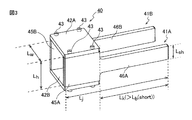
図3は、本実施形態に係るアーム基準位置を合わせるための冶具40の外観構成を示す斜視図である。図3に示す冶具40は、アーム部2へ装着した状態の構成を示している。
FIG. 3 is a perspective view showing an external configuration of the
冶具40は、一対の平板41A,41Bと、一対の連結板42A,42Bと、平板41A,41Bと連結板42A,42Bとを締結する複数の締結具43とから構成される。平板41Aは、基部分45Aと、基部分45Aから伸延する伸延部分46Aとからなる。平板41Bは、平板41Aと同形に構成され、基部分45Bと、基部分45Bから伸延する伸延部分46Bとからなる。
The
本実施形態における冶具40は、締結具43の締結により平板41A,41B、連結板42A,42Bを組み合わせて、図3に示す冶具40を構成し、また締結具43の取り外しにより平板41A,41B、連結板42A,42Bを個々に分離可能である。すなわち、本実施形態における冶具40は、冶具40を用いてアーム部2の原点出しをする場合に、必要に応じて組み立ててアーム部2に装着することができる。
The
基部分45A,45Bは、ほぼ方形に形成され、一辺の中央に伸延部分46A,46Bが形成される。基部分45A,45Bの幅(Lh)は、アーム部2の高さと同等、又は僅かに長く(例えば、1cm以内)、伸延部分46A,46Bの幅(Lsh)は、アーム部2の高さより短い。従って、平板41A,41Bは、T字形に構成される。
The
平板41A,41Bの長手方向の長さ(Lj)は、原点出しをする際に、アーム部2を最も収縮させたアーム基準位置を規定する長さとなる。例えば、平板41A,41Bの長手方向の長さ(Lj)は、13.5cmとする。また、伸延部分46A,46Bの長さ(Lk)は、図9に示すアームカバー6の収縮長(Lb(Short))よりも例えば1cm程度、長く形成される。
The length (Lj) in the longitudinal direction of the
平板41A,41Bの基部分45A,45Bは、少なくとも締結具43を挿入させる穴を形成可能な厚さを有する。締結具43は、例えばねじ部材により構成される。従って、基部分45A,45Bの連結板42A,42Bを装着させる2辺には、それぞれ締結具43(ねじ部材)を係合させるためのねじ穴が例えば2つずつ形成される。
The
連結板42A,42Bは、一対の平板41A,41Bを、アーム部2を挟んで対峙する状態で連結するための部材である。連結板42A,42Bは、例えば方形に形成され、少なくとも相対する2辺が、平板41A,41Bの間隔幅(Lw)を規定する長さに形成される。平板41A,41Bの間隔(Lw)は、アーム部2の幅と同等、又は僅かに長く(例えば、1cm以内)する。
The connection plates 42 </ b> A and 42 </ b> B are members for connecting the pair of flat plates 41 </ b> A and 41 </ b> B in a state of facing each other with the
連結板42A,42Bには、締結具43を貫通させるための貫通穴が、平板41A,41Bの基部分45A,45Bを装着させる辺の近傍に設けられる。連結板42A,42Bに設けられる貫通穴は、平板41A,41Bの基部分45A,45Bに設けられたねじ穴の位置に合わせて形成される。締結具43は、連結板42A,42Bの貫通穴を介して、基部分45A,45Bのねじ穴に係合される。
The connecting
図4は、本実施形態に係る冶具40をアーム部2に装着する方法を示す図である。
FIG. 4 is a diagram illustrating a method of mounting the
冶具40をアーム部2に装着する場合、アーム部2を覆うアームカバー6を手首部4から取り外してアーム部2を露出させる。
When attaching the
まず、平板41A,41Bを1枚の連結板42Bにより連結する。これにより、図4に示すように、平板41A,41B、連結板42Bによりアーム部2を導入することが可能な開口部が形成される。この開口部をアーム部2の下方から合わせて、アーム部2を平板41A,41Bの間に導入する。そして、図4に示すように、連結板42Aを締結具43により平板41A,41Bに固定し、平板41A,41Bを連結する。
First, the
図5は、アーム部2への冶具40の装着が完了した状態を示している。
FIG. 5 shows a state where the attachment of the
前述したように、基部分45A,45Bの幅(Lh)は、アーム部2の高さと同等、又は僅かに長く、また平板41A,41Bの間隔幅(Lw)は、アーム部2の幅と同等、又は僅かに長くなるように構成されている。すなわち、冶具40は、アーム部2と固定されていないため、図5に示すようにアーム部2に装着された状態において、アーム部2に沿って移動可能となる。
As described above, the width (Lh) of the
また、アーム部2が角柱形状に構成され、アームカバー6が筒形状に構成されるため、アーム部2の各面とアームカバー6の内側との間に、ほぼ弓形の間隙が形成される。間隙の幅は、アーム部2の面の中央付近が最も広くなる。また、平板41A,41Bに形成された伸延部分46A,46Bは、基部分45A,45Bの一辺の中央から形成され、その幅(Lsh)がアーム部2の高さより短く構成されている。従って、冶具40がアーム部2に装着されたとき、伸延部分46A,46Bは、アーム部2とアームカバー6との間隙に挿入され、アームカバー6の伸縮に影響しない。
Further, since the
図6及び図7は、冶具40を用いて原点出しをするためにアーム部2の位置決めをした状態を示している。図6は、冶具40の周辺を視認可能とするためにアームカバー6及び第3支持部11cを切欠いて示す図、図7は、アーム部2を伸縮させる方向に対して垂直方向から見たアームカバー6を切り欠いて示すロボットアーム機構1の外観側面を示す図である。
6 and 7 show a state in which the
冶具40をアーム部2に装着した状態でアーム部2を収縮させた場合、基部分45A,45Bの伸延部分46A,46Bが設けられていない側の辺が手首部4の端部50に当接し、伸延部分46A,46Bの先端部が第3支持体11cの射出口39に当接するまで、アーム部2を収縮させることができる。すなわち、平板41A,41Bが手首部4と射出口39とに当接した位置が、アーム部2を最も収縮させた状態となる。アームカバー6は、アーム部2を収縮させる際に、平板41A,41Bの基部分45A,45Bが当接することにより圧縮される。伸延部分46A,46Bの長さ(Lk)は、アームカバー6の収縮長(Lb(Short))よりも長い。このため、アームカバー6が収縮長まで圧縮される前に、伸延部分46A,46Bの先端部が第3支持体11cの射出口39に当接する。
When the
このようにして、冶具40を用いることにより、アーム部2からアームカバー6を取り外すこと無く、アーム部2を安定した状態で位置合わせすることが可能となる。すなわち、冶具40(平板41A,41B)の長さに応じた位置まで正確にアーム部2を収縮させることができるため、その位置を動作制御上の原点(直動関節のアーム基準位置)として原点出しすることにより、安定したアーム部2の送り出し長の制御を実現することが可能となる。
Thus, by using the
なお、前述した実施形態では、冶具40は、2枚の平板41A,41Bを含んでいるが、少なくとも1枚の平板があれば良い。また、本実施形態における冶具40は、アーム部2が角柱形状に構成されているため、板状の4枚の部材(平板41A,41B、連結板42A,42B)を組み合わせて、アーム部2の外周面に沿って装着可能な構成にしているが、アーム部2の外形状に応じた他の形状とすることも可能である。例えば、アーム部2が円柱状に構成されている場合には、アーム部2の外周面に沿って装着することができる円柱部分を有するように冶具を構成する。
In the above-described embodiment, the
また、前述した冶具20は、4つの部材(平板41A,41B、連結板42A,42B)を組み合わせて構成されているが、部材の数は4つでなくても良い。例えば、2つの部材を組み合わせるようにして冶具40を構成することも可能である。
Moreover, although the jig 20 mentioned above is comprised combining four members (
また、例えば、平板41A,連結板42A,平板41B、連結板42Bの順に、それぞれの間をヒンジ機構により連結して、相互に回動可能となるように一体化しても良い。この場合、アーム部2に一体化された部材を取り付け、平板41Aと連結板42Bとを締結具により締結することにより、冶具40をアーム部2に装着することができる。
Further, for example, the
本発明のいくつかの実施形態を説明したが、これらの実施形態は、例として提示したものであり、発明の範囲を限定することは意図していない。これら実施形態は、その他の様々な形態で実施されることが可能であり、発明の要旨を逸脱しない範囲で、種々の省略、置き換え、変更を行うことができる。これら実施形態やその変形は、発明の範囲や要旨に含まれると同様に、特許請求の範囲に記載された発明とその均等の範囲に含まれるものである。 Although several embodiments of the present invention have been described, these embodiments are presented by way of example and are not intended to limit the scope of the invention. These embodiments can be implemented in various other forms, and various omissions, replacements, and changes can be made without departing from the spirit of the invention. These embodiments and their modifications are included in the scope and gist of the invention, and are also included in the invention described in the claims and the equivalents thereof.
1…ロボットアーム機構、2…アーム部、4…手首部、6…アームカバー、10…基部、J1,J2,J3,J4,J5,J6…関節部、11a…第1支持体、11b…第2支持体、11c…第3支持体、40…冶具、41A,41B…平板、42A,42B…連結板、43…締結具。
DESCRIPTION OF SYMBOLS 1 ... Robot arm mechanism, 2 ... Arm part, 4 ... Wrist part, 6 ... Arm cover, 10 ... Base part, J1, J2, J3, J4, J5, J6 ... Joint part, 11a ... 1st support body, 11b ...
Claims (4)
基部分と前記基部分から伸延する伸延部分とからなる一対の平板と、
前記一対の平板を、前記アーム部を挟んで対峙する状態で連結するための連結板と、
前記平板に前記連結板を締結する締結具とを有し、
前記一対の平板の伸延部分は、前記アームカバーの収縮長よりも長く、前記基部分の幅が前記アーム部の高さと同等又は長く、前記伸延部分の幅が前記アーム部の高さより短いT字形に構成され、前記冶具が前記アーム部に装着されたとき前記平板の前記伸延部分は前記アーム部と前記アームカバーとの間隙に挿入されることを特徴とする冶具。 In a jig for adjusting the reference position of the arm part of the linear motion joint formed by covering the linearly-moving prismatic arm part with the arm cover that expands and contracts,
A pair of flat plates comprising a base portion and an extended portion extending from the base portion;
A connecting plate for connecting the pair of flat plates in a state of facing each other with the arm portion interposed therebetween;
A fastener for fastening the connecting plate to the flat plate;
The extended portions of the pair of flat plates are longer than the contracted length of the arm cover, the width of the base portion is equal to or longer than the height of the arm portion, and the width of the extended portion is shorter than the height of the arm portion. The extending portion of the flat plate is inserted into the gap between the arm portion and the arm cover when the jig is mounted on the arm portion.
Priority Applications (1)
| Application Number | Priority Date | Filing Date | Title |
|---|---|---|---|
| JP2015123954A JP6517599B2 (en) | 2015-06-19 | 2015-06-19 | Jig for aligning arm reference position of linear motion joint |
Applications Claiming Priority (1)
| Application Number | Priority Date | Filing Date | Title |
|---|---|---|---|
| JP2015123954A JP6517599B2 (en) | 2015-06-19 | 2015-06-19 | Jig for aligning arm reference position of linear motion joint |
Publications (2)
| Publication Number | Publication Date |
|---|---|
| JP2017007021A true JP2017007021A (en) | 2017-01-12 |
| JP6517599B2 JP6517599B2 (en) | 2019-05-22 |
Family
ID=57761053
Family Applications (1)
| Application Number | Title | Priority Date | Filing Date |
|---|---|---|---|
| JP2015123954A Active JP6517599B2 (en) | 2015-06-19 | 2015-06-19 | Jig for aligning arm reference position of linear motion joint |
Country Status (1)
| Country | Link |
|---|---|
| JP (1) | JP6517599B2 (en) |
Cited By (1)
| Publication number | Priority date | Publication date | Assignee | Title |
|---|---|---|---|---|
| WO2017208870A1 (en) * | 2016-05-30 | 2017-12-07 | ライフロボティクス株式会社 | Linear expansion/contraction mechanism |
Citations (5)
| Publication number | Priority date | Publication date | Assignee | Title |
|---|---|---|---|---|
| JPS6175991U (en) * | 1984-10-24 | 1986-05-22 | ||
| JPH03121792A (en) * | 1989-09-30 | 1991-05-23 | Yaskawa Electric Mfg Co Ltd | Adjusting device for original position of industrial robot |
| JPH06320453A (en) * | 1993-05-13 | 1994-11-22 | Fanuc Ltd | Positioning device for industrial robot |
| JPH0890466A (en) * | 1994-09-19 | 1996-04-09 | Yaskawa Electric Corp | Reference positioning method for industrial robot |
| WO2010070915A1 (en) * | 2008-12-19 | 2010-06-24 | 株式会社川渕機械技術研究所 | Linearly moving extendable mechanism and robot arm equipped with linearly moving extendable mechanism |
-
2015
- 2015-06-19 JP JP2015123954A patent/JP6517599B2/en active Active
Patent Citations (5)
| Publication number | Priority date | Publication date | Assignee | Title |
|---|---|---|---|---|
| JPS6175991U (en) * | 1984-10-24 | 1986-05-22 | ||
| JPH03121792A (en) * | 1989-09-30 | 1991-05-23 | Yaskawa Electric Mfg Co Ltd | Adjusting device for original position of industrial robot |
| JPH06320453A (en) * | 1993-05-13 | 1994-11-22 | Fanuc Ltd | Positioning device for industrial robot |
| JPH0890466A (en) * | 1994-09-19 | 1996-04-09 | Yaskawa Electric Corp | Reference positioning method for industrial robot |
| WO2010070915A1 (en) * | 2008-12-19 | 2010-06-24 | 株式会社川渕機械技術研究所 | Linearly moving extendable mechanism and robot arm equipped with linearly moving extendable mechanism |
Cited By (1)
| Publication number | Priority date | Publication date | Assignee | Title |
|---|---|---|---|---|
| WO2017208870A1 (en) * | 2016-05-30 | 2017-12-07 | ライフロボティクス株式会社 | Linear expansion/contraction mechanism |
Also Published As
| Publication number | Publication date |
|---|---|
| JP6517599B2 (en) | 2019-05-22 |
Similar Documents
| Publication | Publication Date | Title |
|---|---|---|
| JP6443875B2 (en) | Robot arm mechanism | |
| US7275332B2 (en) | Multi-axis positioning apparatus | |
| CN107148328B (en) | Mechanical arm mechanism | |
| JP2016124069A (en) | Robot arm mechanism and direct-acting expansion mechanism | |
| JP6810053B2 (en) | Linear telescopic mechanism | |
| JP6734364B2 (en) | Linear motion telescopic mechanism and robot arm mechanism | |
| CN108698237B (en) | Direct-acting telescopic mechanism and mechanical arm mechanism with same | |
| WO2018025725A1 (en) | Robot arm mechanism | |
| JP6711911B2 (en) | Linear expansion mechanism | |
| WO2016098815A1 (en) | Robot arm mechanism | |
| JP2017007021A (en) | Tool for adjusting arm reference position of direct-acting joint | |
| TW201741099A (en) | Linear extension and retraction mechanism | |
| WO2016108280A1 (en) | Linear-motion extending/contracting mechanism and robot arm mechanism | |
| WO2017170304A1 (en) | Torsional rotation joint mechanism, robot arm mechanism, and cantilever rotation mechanism | |
| JP6662581B2 (en) | Robot arm mechanism | |
| JP2016160964A (en) | Translatory expansion mechanism and robot arm mechanism | |
| JP2019069478A (en) | Robot arm mechanism and direct-acting expansion mechanism | |
| JP2016168646A (en) | Straight-motion extension and contraction mechanism and robot arm mechanism | |
| US20220388149A1 (en) | Device for a microactuator, and microactuator equipped with such a device | |
| JP2016160963A (en) | Warping expansion mechanism and robot arm mechanism | |
| WO2017150318A1 (en) | Robot arm mechanism, and direct-acting extension/retraction mechanism | |
| JP2019022943A (en) | Robot arm mechanism | |
| JPH01257584A (en) | Calibration jig of horizontal articulated robot |
Legal Events
| Date | Code | Title | Description |
|---|---|---|---|
| A521 | Request for written amendment filed |
Free format text: JAPANESE INTERMEDIATE CODE: A523 Effective date: 20170216 |
|
| A621 | Written request for application examination |
Free format text: JAPANESE INTERMEDIATE CODE: A621 Effective date: 20180518 |
|
| TRDD | Decision of grant or rejection written | ||
| A01 | Written decision to grant a patent or to grant a registration (utility model) |
Free format text: JAPANESE INTERMEDIATE CODE: A01 Effective date: 20190319 |
|
| A977 | Report on retrieval |
Free format text: JAPANESE INTERMEDIATE CODE: A971007 Effective date: 20190320 |
|
| A61 | First payment of annual fees (during grant procedure) |
Free format text: JAPANESE INTERMEDIATE CODE: A61 Effective date: 20190418 |
|
| R150 | Certificate of patent or registration of utility model |
Ref document number: 6517599 Country of ref document: JP Free format text: JAPANESE INTERMEDIATE CODE: R150 |
|
| S801 | Written request for registration of abandonment of right |
Free format text: JAPANESE INTERMEDIATE CODE: R311801 |
|
| ABAN | Cancellation due to abandonment | ||
| R350 | Written notification of registration of transfer |
Free format text: JAPANESE INTERMEDIATE CODE: R350 |