WO2016072190A1 - Maintenance unit and liquid jetting device - Google Patents
Maintenance unit and liquid jetting device Download PDFInfo
- Publication number
- WO2016072190A1 WO2016072190A1 PCT/JP2015/078175 JP2015078175W WO2016072190A1 WO 2016072190 A1 WO2016072190 A1 WO 2016072190A1 JP 2015078175 W JP2015078175 W JP 2015078175W WO 2016072190 A1 WO2016072190 A1 WO 2016072190A1
- Authority
- WO
- WIPO (PCT)
- Prior art keywords
- maintenance
- unit
- liquid
- liquid ejecting
- storage medium
- Prior art date
Links
Images
Classifications
-
- B—PERFORMING OPERATIONS; TRANSPORTING
- B41—PRINTING; LINING MACHINES; TYPEWRITERS; STAMPS
- B41J—TYPEWRITERS; SELECTIVE PRINTING MECHANISMS, i.e. MECHANISMS PRINTING OTHERWISE THAN FROM A FORME; CORRECTION OF TYPOGRAPHICAL ERRORS
- B41J2/00—Typewriters or selective printing mechanisms characterised by the printing or marking process for which they are designed
- B41J2/005—Typewriters or selective printing mechanisms characterised by the printing or marking process for which they are designed characterised by bringing liquid or particles selectively into contact with a printing material
- B41J2/01—Ink jet
- B41J2/135—Nozzles
- B41J2/165—Preventing or detecting of nozzle clogging, e.g. cleaning, capping or moistening for nozzles
- B41J2/16517—Cleaning of print head nozzles
- B41J2/16535—Cleaning of print head nozzles using wiping constructions
- B41J2002/1655—Cleaning of print head nozzles using wiping constructions with wiping surface parallel with nozzle plate and mounted on reels, e.g. cleaning ribbon cassettes
-
- B—PERFORMING OPERATIONS; TRANSPORTING
- B41—PRINTING; LINING MACHINES; TYPEWRITERS; STAMPS
- B41J—TYPEWRITERS; SELECTIVE PRINTING MECHANISMS, i.e. MECHANISMS PRINTING OTHERWISE THAN FROM A FORME; CORRECTION OF TYPOGRAPHICAL ERRORS
- B41J2/00—Typewriters or selective printing mechanisms characterised by the printing or marking process for which they are designed
- B41J2/005—Typewriters or selective printing mechanisms characterised by the printing or marking process for which they are designed characterised by bringing liquid or particles selectively into contact with a printing material
- B41J2/01—Ink jet
- B41J2/135—Nozzles
- B41J2/165—Preventing or detecting of nozzle clogging, e.g. cleaning, capping or moistening for nozzles
- B41J2/16517—Cleaning of print head nozzles
- B41J2/16552—Cleaning of print head nozzles using cleaning fluids
- B41J2002/16558—Using cleaning liquid for wet wiping
Definitions
- the present invention relates to a maintenance unit used for maintenance of a liquid ejecting unit and a liquid ejecting apparatus such as a printer to which the maintenance unit is detachably mounted.
- a liquid ejecting head for ejecting ink for printing and a wiper cassette mounted with a long wiping member for wiping the liquid attached to the liquid ejecting head are detachably mounted.
- an ink jet printer having a wiper holder.
- the wiper cassette is accommodated in a state in which both end sides of the wiping member are respectively wound around a roller, and when both rollers are rotated, the wiping member can be unwound and wound. Then, by the rotation of both rollers, an unused portion of the wiping member is disposed between the both rollers, and the liquid ejection head is wiped by this unused portion.
- both rollers When both rollers are rotated, the wiping member can be unwound and wound. Then, by the rotation of both rollers, an unused portion of the wiping member is disposed between the both rollers, and the liquid ejection head is wiped by this unused portion.
- Such a problem is not limited to the wiping member that wipes the liquid jet head that jets the ink, but the maintenance of the liquid jet unit using a maintenance member that has a limited amount of use, expiration date, etc. It is generally common.
- An object of the present invention is to provide a maintenance unit and a liquid ejecting apparatus capable of appropriately managing a maintenance member used for maintenance of a liquid ejecting unit.
- a maintenance unit for solving the above problems is a maintenance unit detachably mounted on a liquid ejecting apparatus having a liquid ejecting unit for ejecting a liquid, and a long maintenance member used for maintenance of the liquid ejecting unit And a storage medium configured to store information on the maintenance member.
- the storage medium included in the maintenance unit stores the information related to the maintenance member, management of the maintenance member used for the maintenance of the liquid ejecting unit is appropriately performed based on the information stored in the storage medium.
- the storage medium is configured to store a value corresponding to the number of executions of maintenance performed using the maintenance member. According to this configuration, the maintenance amount of the maintenance member is managed while the maintenance amount of the maintenance member is managed by grasping the usage amount of the maintenance member based on the value corresponding to the number of times of execution of the maintenance stored in the storage medium. Can be performed.
- the storage medium is configured to store a value corresponding to the movement amount of the maintenance member involved in the maintenance of the liquid ejecting unit.
- the maintenance unit is attached to a different liquid ejecting apparatus in the middle of use by grasping the usage amount of the maintenance member based on the value corresponding to the movement amount of the maintenance member stored in the storage medium. Even if it does, the usage-amount of a maintenance member can be integrated and the residual amount of a maintenance member can be managed correctly.
- the storage medium is configured to store information on the liquid ejecting apparatus on which the maintenance unit is mounted. According to this configuration, the storage medium stores the information on the liquid ejecting apparatus to which the maintenance unit is attached, so that the maintenance unit is attached even if, for example, the maintenance unit is reattached to a different liquid ejecting apparatus during use. It is possible to grasp the liquid injection device that has been
- the storage medium is configured to store information on a date when the maintenance unit is attached to the liquid ejecting apparatus. According to this configuration, the storage unit stores the information on the date when the maintenance unit is mounted on the liquid ejecting apparatus, thereby managing the expiration date of the maintenance member when the expiration date of the maintenance member, etc. Maintenance can be carried out properly.
- the storage medium is configured to store information on a manufacturing date of the maintenance unit. According to this configuration, the storage medium stores the information on the manufacturing date of the maintenance unit, whereby maintenance of the liquid ejecting unit is appropriately performed while managing the expiration date of the maintenance member, etc. can do.
- the storage medium is configured to store information on the liquid ejecting apparatus to which the maintenance unit can be attached. According to this configuration, when there is a maintenance member and an inappropriate maintenance member that are appropriate to be used for a certain liquid ejecting unit, the information on the liquid ejecting apparatus to which the maintenance unit stored in the storage medium can be attached. By referring to the above, it is possible to avoid the execution of the maintenance of the liquid injection part by an inappropriate maintenance member.
- the storage medium is configured to store information on a liquid impregnated in the maintenance member.
- the information on the liquid to be impregnated in the maintenance member stored by the storage medium is referred to By doing this, it is possible to avoid the execution of the maintenance of the liquid jet unit by the maintenance member impregnated with the inappropriate liquid.
- the maintenance unit further includes a holding unit that holds the maintenance member in a movable state, and a storage unit that stores the holding unit.
- a liquid ejecting apparatus that solves the above problems includes a liquid ejecting unit that ejects a liquid, a mounting unit to which the maintenance unit used for maintenance of the liquid ejecting unit is detachably mounted, and the storage medium of the maintenance unit And a control unit configured to execute a maintenance operation of the liquid ejecting unit based on the information stored in the control unit.
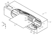
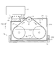
- FIG. 1 is a perspective view schematically showing an embodiment of a liquid ejecting apparatus.
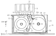
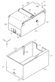
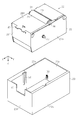
- Sectional drawing which shows typically one Embodiment of a maintenance unit. The perspective view which looked at the maintenance unit with which an installation part is equipped from one direction. The perspective view which looked at the maintenance unit with which an installation part is equipped from the other direction. Sectional drawing which shows the example of a change of a maintenance unit and a mounting part.
- the liquid ejecting apparatus is, for example, an ink jet printer that performs recording (printing) by ejecting ink, which is an example of liquid, onto a medium such as paper.
- the liquid ejecting apparatus 11 includes a housing 12, a medium support 13 for supporting the medium S in the housing 12, and a liquid for the medium S supported by the medium support 13.
- a display unit 55 made of, for example, a liquid crystal monitor or the like is provided.
- the liquid ejecting apparatus 11 includes a control unit 20 that is disposed at an arbitrary position in the housing unit 12 and controls the liquid ejecting unit 15 and the maintenance device 16.
- the liquid ejecting unit 15 performs recording (printing) by ejecting the liquid in the ejection direction Z from the nozzle 14 onto the medium S conveyed in the conveyance direction Y on the medium support unit 13 under the control of the control unit 20. .
- the liquid ejecting unit 15 is held by a carriage 18 that reciprocates along a guide unit 17 extending in the movement direction X.
- the carriage 18 is detachably mounted with one or more liquid containers 19 containing liquid supplied toward the liquid ejecting unit 15.
- the movement direction X, the conveyance direction Y, and the injection direction Z are directions crossing each other (preferably, orthogonally).
- the injection direction Z since the injection direction Z is a direction intersecting the horizontal direction, the injection direction Z may be referred to as the downward direction, and the opposite direction may be referred to as the upward direction.
- the area where the medium support 13 is disposed is referred to as an ejection area, and the position where the maintenance device 16 is disposed is referred to as a maintenance area.
- the maintenance area is a position aligned with the injection area in the moving direction X, and is disposed outside the injection area (right side in FIG. 1).
- the movement direction X is a direction from the maintenance area to the injection area.
- the maintenance device 16 of the present embodiment performs wiping for wiping the opening surface 15 a where the nozzle 14 opens in the liquid ejecting unit 15 using a long maintenance member 21 as a maintenance operation. It is a thing.
- the maintenance member 21 used for the maintenance of the liquid ejecting unit 15 is, for example, an absorbing member capable of absorbing a liquid made of non-woven fabric or the like, and it is preferable that the liquid for maintenance be impregnated beforehand.
- the impregnating solution to be impregnated into the absorbing member one selected for the purpose of improving or maintaining the wiping property is used according to the type of the liquid sprayed by the liquid spraying unit 15.
- the liquid to be ejected by the liquid ejecting unit 15 for example, an aqueous ink in which a coloring agent is added to a solvent containing water as a main component, and an organic solvent based ink in which a coloring agent is added to a solvent It is also called water-based ink.
- the type of ink there are dye ink using a water-soluble dye as a colorant and pigment ink using a pigment as a colorant.
- an ink which vaporizes a solvent of the ink landed on the medium S to fix the coloring agent on the medium an ink which irradiates a light beam such as UV to fix the ink, and the like.
- the liquid jetted by the liquid jet unit 15 is a pigment ink
- the absorbing member contains the impregnating solution, the pigment particles are easily moved from the surface of the absorbing member to the inside, and the pigment particles are less likely to remain on the surface of the absorbing member.
- the type of the impregnation liquid is not particularly limited as long as it is a liquid that can move the inorganic pigment particles from the surface of the absorbing member to the inside.
- the surface tension of the impregnating solution is preferably 45 mN / m or less, more preferably 35 mN / m or less.
- the surface tension is measured at a liquid temperature of 25 ° C. by the Wilhelmy method using a generally used surface tension meter (for example, surface tension meter CBVP-Z manufactured by Kyowa Interface Science Co., Ltd.). The method can be illustrated.
- the content of the impregnating solution is preferably 10% by mass or more and 200% by mass or less, more preferably 10% by mass or more and 120% by mass or less, and more preferably 30% by mass or more and 100% by mass with respect to 100% by mass of the absorbing member. It is further preferable that the content is at most mass%.
- the content of the impregnating solution to 200% by mass or less with respect to 100% by mass of the absorbing member, the remaining of the impregnating solution on the opening surface 15a is further suppressed, and air bubbles enter the nozzle 14 together with the impregnating solution.
- additives examples include resins, antifoaming agents, surfactants, water, organic solvents, pH adjusters and the like. Each of these components may be added alone or in combination of two or more, and their contents may be optionally changed.
- the impregnating solution may contain a large amount of an acidic moisturizing agent such as polyethylene glycol or glycerin.
- the acidic impregnating solution may be an ink composition (usually , And the basicity of pH 7.5 or more) can be avoided. Thereby, the ink composition can be inhibited from shifting to the acidic side, and the storage stability of the ink composition is further maintained.
- a moisturizer which may be contained in an impregnating solution, it can be used without being particularly limited as long as it can be generally used for ink and the like.
- a humectant a high-boiling humectant having a boiling point of preferably 180 ° C. or more, more preferably 200 ° C. or more at an equivalent pressure of 1 atm can be used.
- the boiling point of the moisturizing agent is within the above range, volatilization of volatile components in the impregnating solution can be suppressed, so that the inorganic pigment-containing ink composition in contact with the impregnating solution can be surely wetted and wiped off effectively. be able to.
- high boiling point humectants include ethylene glycol, propylene glycol, diethylene glycol, triethylene glycol, pentamethylene glycol, trimethylene glycol, 2-butene-1,4-diol, 2-ethyl-1,3-hexanediol, Examples include 2-methyl-2,4-pentanediol, tripropylene glycol, polyethylene glycol, polypropylene glycol, 1,3-propylene glycol, isopropylene glycol, isobutylene glycol, glycerin, mesoerythritol, and pentaerythritol.
- a moisturizer may be used individually by 1 type, and may mix and use 2 or more types.
- the content of the humectant is preferably 10 or more and 100% by mass or less based on the total mass (100% by mass) of the impregnating solution.
- the content of the humectant of 100% by mass with respect to the total mass of the impregnating solution indicates that all the components of the impregnating solution are the humectant.
- the penetrant is not particularly limited as long as it can be generally used for ink etc. However, in a solution of 90% by weight of water and 10% by weight of penetrant, the surface tension of the solution is 45 mN / m or less It can also be adopted as a penetrant.
- the penetrant is not particularly limited, but is selected, for example, from the group consisting of alkanediols having 5 to 8 carbon atoms, glycol ethers, acetylene glycol surfactants, siloxane surfactants, and fluorine surfactants.
- the measurement of surface tension can be performed by the above-mentioned method.
- the content of the penetrant in the impregnating solution is preferably 1% by mass to 40% by mass, and more preferably 3% by mass to 25% by mass.
- the content of the penetrant in the impregnating solution is 1% by mass or more, it tends to be more excellent in wiping properties, and by being 40% by mass or less, the penetrant is contained in the ink in the vicinity of the nozzle It is possible to attack the pigment and prevent the dispersion stability from breaking and causing aggregation.
- the alkanediols having 5 to 8 carbon atoms are not particularly limited, and examples thereof include 1,2-pentanediol, 1,5-pentanediol, 1,2-hexanediol, 1,6-hexanediol, and the like. -Heptanediol, 2-ethyl-1,3-hexanediol, 2,2-dimethyl-1,3-propanediol, 2,2-dimethyl-1,3-hexanediol and the like.
- the alkanediols having 5 to 8 carbon atoms may be used alone or in combination of two or more.
- glycol ethers are not particularly limited.
- the acetylene glycol surfactant is not particularly limited, and examples thereof include a compound represented by the following formula, and the like.
- R 1 * , R 2 * , R 3 * , and R 4 * each independently represent an alkyl group (preferably an alkyl group having 1 to 6 carbon atoms).
- R 1 * , R 2 * , R 3 * , and R 4 * each independently represent an alkyl group (preferably an alkyl group having 1 to 6 carbon atoms).
- acetylene glycol surfactants represented by the formula (1) preferably 2,4,7,9-tetramethyl-5-decyne-4,7-diol, 3,6-dimethyl-4-octin- Examples include 3,6-diol, 3,5-dimethyl-1-hexyne-3ol and the like.
- acetylene glycol surfactant represented by the formula (1), and specific examples thereof include Surfynol 82, 104, 440, 465, 485, or TG (all of which are AirProducts and And Olfin STG, Olfin E1010 (trade name) (manufactured by Nisshin Chemical Co., Ltd.), and the like.
- the acetylene glycol surfactants may be used alone or in combination of two or more.
- siloxane type surfactant Although it does not specifically limit as a siloxane type surfactant, For example, what is represented by following formula (2) or (3) etc. are mentioned.
- R 1 , R 2 , R 3 , R 4 , R 5 , R 6 and R 7 each independently represent an alkyl group having 1 to 6 carbon atoms, preferably a methyl group
- g represents an integer of 0 or more, preferably 1 to 3, and more preferably 1.
- p and q each represent an integer of 0 or more, preferably 1 to 5. However, p + q is an integer of 1 or more, preferably p + q is 2 to 4.
- R 1 to R 7 all represent a methyl group
- j represents 1 to 2
- k represents 1 to 2
- g is 1 to 2.
- a compound in which p is an integer of 1 or more and 5 or less and q is 0 is preferable.
- R represents a hydrogen atom or a methyl group
- a represents an integer of 2 to 18
- m represents an integer of 0 to 50
- n represents an integer of 1 to 5.
- the siloxane-based surfactant represented by the formula (3) is not particularly limited.
- R represents a hydrogen atom or a methyl group
- a represents an integer of 7 to 11
- m is an integer of 30 to 50
- R represents a hydrogen atom or a methyl group
- a represents an integer of 9 to 13
- m represents an integer of 2 to 4
- n is 1 to 2
- R is a hydrogen atom or a methyl group
- a is an integer of 6 to 18
- m is an integer of
- n is an integer of 1
- R is a hydrogen atom
- a Preferred is a compound or the like in which is an integer of 2 to 5
- m is an integer of 20 to 40
- n is an integer of 3 to 5.
- Siloxane-based surfactants are commercially available and may be commercially available.
- Olfin PD-501 manufactured by Nisshin Chemical Industry Co., Ltd.
- Olfin PD-570 Natural Chemical Industry Co., Ltd.
- BYK-347 made by Bick Chemie, Inc.
- BYK-348 made by Bick Chemie, Inc.
- the above-mentioned siloxane type surfactant may be used alone or in combination of two or more.
- fluorinated surfactants are known as solvents that exhibit good wettability to low-absorbing non-absorbing recording media.
- the fluorine-based surfactant is not particularly limited, but can be appropriately selected depending on the purpose.
- perfluoroalkyl sulfonate, perfluoroalkyl carboxylate, perfluoroalkyl phosphate, perfluoroalkyl ethylene Oxide adducts, perfluoroalkyl betaines, perfluoroalkylamine oxide compounds and the like can be mentioned.
- the fluorine-based surfactant one appropriately synthesized may be used, or a commercially available product may be used.
- Commercially available products include, for example, S.144, S.145 (Asahi Glass Co., Ltd.); FC.170C, FC.430, Florard.FC4430 (Sumitomo 3M Co., Ltd.); FSO, FSO.100, FSN, FSN.100 FS ⁇ 300 (manufactured by Dupont); FT ⁇ 250, 251 (manufactured by Neos Co., Ltd.) and the like.
- FSO manufactured by Dupont FSO ⁇ 100, FSN, FSN ⁇ 100, FS ⁇ 300 are preferable.
- the fluorinated surfactants may be used alone or in combination of two or more.
- the impregnating liquid impregnated in the absorbing member may be, for example, a compound represented by the following general formula (I), an ester, And at least one organic solvent selected from the group consisting of dibasic acid esters (hereinafter also referred to as “specific organic solvent”) is preferably contained. These specific organic solvents may be used alone or in combination of two or more.
- the specific organic solvent is excellent in the function of dissolving (softening) the non-aqueous ink attached to the opening surface 15a, it is possible to wipe the opening surface 15a by suppressing aggregation of components contained in the non-aqueous ink. Efficiency is improved.
- R 1 -O- (R 2 -O) n -R 3 (I)
- R 1 represents a hydrogen atom, an aryl group or an alkyl group having 1 to 6 carbon atoms
- R 2 represents an alkylene group having 2 to 4 carbon atoms
- R 3 represents Represents an aryl group or an alkyl group having 1 to 6 carbon atoms
- n represents an integer of 1 to 9
- Examples of the "aryl group” include phenyl group, benzyl group, tolyl group, xylyl group, naphthyl group, methylnaphthyl group, benzylphenyl group, biphenyl group and the like.
- alkyl group having 1 or more and 6 or less carbon atoms may be a linear or branched alkyl group, and examples thereof include a methyl group, an ethyl group, an n-propyl group, an iso-propyl group, and an n -Butyl, sec-butyl, tert-butyl, pentyl or hexyl and the like.
- alkylene group having 2 to 4 carbon atoms include ethylene group, n-propylene group, isopropylene group, and butylene group.
- R 1 is preferably a hydrogen atom or an alkyl group having 2 to 4 carbon atoms.
- R 3 is preferably an alkyl group having 2 to 4 carbon atoms.
- n is preferably an integer of 3 or more and 6 or less.
- n is preferably an integer of 3 or more and 6 or less.
- the action of dissolving (softening) the non-aqueous ink is improved, and the wiping efficiency is further improved.
- Specific examples of the compound represented by the above general formula (I) include alkylene glycol monoethers and glycol ethers such as alkylene glycol diethers.
- the glycol ethers can be used singly or in combination of two or more.
- alkylene glycol monoether for example, ethylene glycol monomethyl ether, ethylene glycol monoethyl ether, ethylene glycol monoisopropyl ether, ethylene glycol monobutyl ether, ethylene glycol monohexyl ether, ethylene glycol monophenyl ether, diethylene glycol monomethyl ether, diethylene glycol monoethyl Ether, diethylene glycol monobutyl ether, diethylene glycol monohexyl ether, diethylene glycol monobenzyl ether, triethylene glycol monomethyl ether, triethylene glycol monoethyl ether, triethylene glycol monobutyl ether, tetraethylene glycol monomethyl ether, Laethylene glycol monoethyl ether, tetraethylene glycol monobutyl ether, pentaethylene glycol monomethyl ether, pentaethylene glycol monoethyl ether, pentaethylene glycol monobutyl ether, propylene glycol monomethyl ether, propylene
- alkylene glycol diether for example, ethylene glycol dimethyl ether, ethylene glycol diethyl ether, ethylene glycol dibutyl ether, diethylene glycol dimethyl ether, diethylene glycol diethyl ether, diethylene glycol ethyl methyl ether, diethylene glycol dibutyl ether, diethylene glycol butyl methyl ether, triethylene glycol dimethyl ether, triethylene glycol Ethylene glycol diethyl ether, triethylene glycol dibutyl ether, triethylene glycol butyl methyl ether, tetra ethylene glycol dimethyl ether, tetra ethylene glycol diethyl ether, tetra ethylene glycol dibutyl ether, propylene glycol Methyl ether, propylene glycol diethyl ether, dipropylene glycol dimethyl ether, dipropylene glycol diethyl ether, and the like.
- esters examples include organic solvents in which R is a hydrogen atom, an alkyl group, an aryl group or a glycol ether group, and R' is an alkyl group or an aryl group.
- esters glycol ether esters are preferably used.
- dibasic acid esters include monoesters and diesters of dicarboxylic acids (for example, aliphatic dicarboxylic acids such as glutaric acid, adipic acid and succinic acid). Specifically, dimethyl-2-methylglutarate and the like can be mentioned.
- a compound represented by the above general formula (I) from the viewpoint of being excellent in the action of dissolving (softening) the non-aqueous ink. It is preferable to use what has a normal boiling point of 170 degreeC or more as said specific organic solvent, and it is more preferable to use what a normal boiling point is 250 degreeC or more. As a result, the occurrence of clogging of the nozzle 14 due to the drying of the impregnating liquid can be reduced, and therefore the ejection stability of the non-aqueous ink is improved.
- the above-mentioned specific organic solvent it is preferable to use one having a vapor pressure at 20 ° C. of 1 hPa or less, more preferably 0.5 hPa or less, and more preferably 0.1 hPa or less Is even more preferable, and it is particularly preferable to use one which is 0.01 hPa or less.
- the surface tension in 20 degreeC is 25 mN / m or more and 35 mN / m or less as said specific organic solvent.
- the surface tension is measured by using an automatic surface tension meter CBVP-Z (manufactured by Kyowa Interface Science Co., Ltd.) to confirm the surface tension when the platinum plate is wetted with an organic solvent under an environment of 20 ° C. can do.
- the lower limit of the content of the specific organic solvent is preferably 30% by mass or more, and more preferably 50% by mass or more based on the total mass (100% by mass) of the impregnating solution. When the content of the specific organic solvent is 50% by mass or more, the wiping efficiency of the opening surface 15a is further improved.
- the upper limit of the content of the specific organic solvent to the impregnating solution is not limited and may be 100% by mass.
- the impregnating solution impregnated in the absorbing member contains 10 parts by mass or more of a specific organic solvent based on 100 parts by mass of the absorbing member. Is preferably contained, more preferably 15 parts by mass or more, still more preferably 20 parts by mass or more, still more preferably 40 parts by mass or more, and 50 parts by mass or more. Is particularly preferred.
- the upper limit thereof is preferably 150 parts by mass or less, and more preferably 100 parts by mass or less.
- the amount is 150 parts by mass or less, since the ink is easily absorbed by the absorbing member, ejection failure or non-ejection of the nozzle 14 due to the remaining ink after wiping does not easily occur, and the ejection stability of the ink is improved.
- the impregnating liquid impregnated in the absorbing member may contain an organic solvent other than the above specific organic solvent, and further, the surface activity You may contain the substance for providing predetermined
- the maintenance device 16 has a box-like mounting portion 23 on which a maintenance unit 22 (see FIG. 2) having a maintenance member 21 is detachably mounted, and the mounting portion 23 along the guide frame 24. And a drive mechanism 25 that reciprocates in the moving direction X.
- the maintenance unit 22 holds information on the holding portion 27 which holds the maintenance member 21 in the movable state in the holding portion 26, the holding portion 26 which holds the holding portion 27, and information on the maintenance member 21. And a storage medium 28 for storing.
- the top surface 26 t of the accommodation unit 26 is exposed toward the liquid ejecting unit 15.
- connection terminal 38 formed of a plate spring or the like is disposed at a position where it can contact the connection portion of the storage medium 28 of the maintenance unit 22 mounted on the mounting portion 23.
- the connection terminal 38 is electrically connected to the control unit 20 (see FIG. 1).
- the control unit 20 reads the information stored in the storage medium 28 via the connection terminal 38. , Write information to the storage medium 28.
- An opening 29 is provided on the top surface 26 t of the housing 26, and a part of the maintenance member 21 is exposed through the opening 29.
- the portion of the maintenance member 21 exposed from the opening 29 is referred to as the wiping unit 31.
- the holding unit 27 includes a delivery roller 32 around which the base end side portion of the maintenance member 21 is wound, a take-up roller 33 for taking up the tip side portion of the maintenance member 21 that is unwound along with the rotation of the delivery roller 32
- the winding rollers 34, 35, 36, 37 apply tension to the maintenance member 21 positioned between the feeding roller 32 and the winding roller 33, and change the direction in which they are laid out. Can be changed arbitrarily.
- the winding roller 36 which is one of the winding rollers 34, 35, 36, 37 is disposed such that a part of the circumferential surface thereof protrudes from the opening 29 of the housing portion 26. Therefore, the portion wound around the winding roller 36 in the maintenance member 21 becomes the wiping unit 31. Then, the maintenance member 21 is moved along with the rotation of the feeding roller 32 and the winding roller 33, whereby the wiping portion 31 disposed in the opening 29 is sequentially changed to an unused portion.
- the maintenance unit 22 is consumed as it is used, It is exchanged for a new one. That is, the used maintenance unit 22 is removed from the mounting unit 23, and another unused maintenance unit 22 is mounted to the mounting unit 23.
- the moving direction X of the accommodation portion 26 in the moving direction X is the longitudinal direction
- the wiping direction 31 is in the vicinity of the center in the longitudinal direction of the accommodation portion 26. It is arranged to be in the longitudinal direction.
- one end side of the accommodation portion 26 in the longitudinal direction than the opening 29 is a tip end side
- the other end side in the longitudinal direction than the opening 29 is The side which is a curved surface
- the proximal side is referred to as a tip end surface 26f
- the surface of the base end intersecting with the top surface 26t is referred to as a base end surface 26r
- the top surface 26t, the tip surface 26f and the base end surface 26r The intersecting surfaces are called side surfaces 26s.
- the wall facing the front end face 26f is a front wall 23f
- the wall facing the base end face 26r is a rear wall 23r
- the wall facing the side 26s is a side wall It is called 23s.
- An elastic piece portion 41 whose upper end side is a fixed end to the accommodation portion 26 and whose lower end side is a free end is provided at a lower position of the base end surface 26 r of the accommodation portion 26.
- the elastic piece portion 41 is elastically deformable in the moving direction X with the fixed end on the upper end side as a fulcrum. Then, at the lower end which is a free end in the elastic piece portion 41, a locking claw 42 is protruded outward.
- a locking hole 52 to which the locking claw 42 of the elastic piece 41 can be engaged is formed at a lower position on the rear wall 23r of the mounting portion 23.
- a finger hook 43 projecting from the top surface 26t in a direction from the base end to the distal end is provided in a protruding manner.
- the finger hook portion 43 is for the user to hook a fingertip when removing the maintenance unit 22 from the mounting portion 23.
- a notch 53 is formed at the upper end of the front wall 23 f of the mounting portion 23. Then, when the maintenance unit 22 is mounted to the mounting portion 23, the finger hook portion 43 of the maintenance unit 22 is exposed to the outside of the mounting portion 23 through the cutout portion 53 (see FIG. 2).
- the engagement protrusion 44 having a substantially cylindrical shape is at a position slightly closer to the tip than the center in the longitudinal direction and near the approximate center in the vertical direction (the injection direction Z). Is projected.
- a guide groove 54 extending downward from the upper end to the vicinity of the center in the vertical direction is provided in the inside portion of both side walls 23s of the mounting portion 23 at a position slightly closer to the tip than the center in the longitudinal direction.
- the width of the opening at the upper end of the guide groove 54 is preferably set to be slightly larger than the diameter of the engagement protrusion 44, and the groove width is preferably narrowed gradually toward the lower side.
- mist consisting of droplets smaller than the droplets is generated as a subsidiary.
- mist adheres to the periphery of the nozzle 14 and gradually increases to become droplets, the enlarged droplets come in contact with the droplets ejected from the nozzle 14 so that the flying direction of the ejected droplets Change the print quality and may reduce the print quality.
- the carriage 18 moves to the maintenance area, and the maintenance device 16 performs wiping using the maintenance member 21.
- the wiping unit 31 wipes the opening surface 15 a of the liquid ejecting unit 15 (see FIG. See Figure 2).
- the liquid discharged from the nozzle 14 is the opening surface 15a. It may stick to the Also in such a case, the maintenance device 16 performs the wiping using the maintenance member 21 described above.
- the maintenance member 21 absorbs the mist attached to the liquid ejecting unit 15 and the liquid attached to the opening surface 15 a as the liquid is discharged, and the paper dust adhering to the liquid ejecting unit 15 And the like are wiped off by the maintenance member 21.
- the feeding roller 32 and the winding roller 33 rotate to move the maintenance member 21 and change the wiping unit 31 exposed from the opening 29 to an unused portion.
- the feeding roller 32 and the winding roller 33 rotate to move the maintenance member 21 when the mounting unit 23 moves along the moving direction X and the wiping unit 31 is in contact with the liquid ejecting unit 15. In this case, the wiping performance of the wiping unit 31 can be improved.
- the storage medium 28 stores at least one of the information listed below. (1) A value corresponding to the number of times of maintenance performed using the maintenance member 21.
- Information on the liquid impregnated in the maintenance member 21 is information on the use history of the maintenance member 21 and is, for example, an accumulated value of the number of times the wiping is performed. Alternatively, if the number of maintenances that can be performed before the maintenance unit 22 becomes unusable is set as the number of lifetimes, the ratio of the number of executions to the number of lifetimes, the number of remaining times until the number of lifetimes, etc. It is also good.
- (2) is information on the use history of the maintenance member 21. For example, the number of times the maintenance member 21 is moved with wiping, the number of rotations of the feeding roller 32 or the winding roller 33, and a predetermined measurement position It is a cumulative value of the length of the maintenance member 21 or the like. Alternatively, the ratio of the movement distance to the total length of the maintenance member 21, the remaining length of the unused portion, the ratio of the remaining length of the unused portion to the total length of the maintenance member 21, or the like may be used.
- the storage medium 28 stores information when one maintenance unit 22 is used among a plurality of different liquid ejecting apparatuses. . Then, each time the maintenance unit 22 is attached to the liquid ejecting apparatus, the storage medium 28 is a maintenance unit that specifies the type of the attached liquid ejecting apparatus and the type of liquid ejected by the liquid ejecting apparatus. The information 22 is stored as information on the attached liquid ejecting apparatus.
- (4) is information on the use history of the maintenance member 21. For example, the day when the maintenance unit 22 is first attached to the liquid ejecting apparatus may be used, or the maintenance unit 22 has its expiration date set. In the case where the maintenance unit 22 is first attached to the liquid ejecting apparatus, it may be the remaining number of days until the expiration date.
- (5) may be the manufacturing date of the maintenance unit 22, or when the expiration date is set in the maintenance unit 22, it may be the remaining number of days from the manufacturing date to the expiration date.
- the storage medium 28 store data as the liquid to be jetted, the impregnating liquid, or the type of the liquid jet apparatus.
- the impregnating liquid is selected to have a property suitable for the liquid jetted by the liquid jet unit 15, it is not preferable that such an impregnating liquid adheres to the liquid jet unit 15 which jets another type of liquid.
- the composition of the impregnating liquid is optimally designed in accordance with the composition of the ink to be used, the compatibility with the liquid jet unit 15 using ink whose combination is not supposed is through the maintenance member 21 having a history of use When the impregnation solution of the above is attached, foreign matter may precipitate from the ink in contact with the impregnation solution.
- the deposited foreign matter may be fixed to the opening face 15a and not wiped off, or the water repellent film of the opening face 15a may be damaged by wiping the opening face 15a in the state where the deposited foreign matter is attached.
- the pigments used in the pigment ink are those which are respectively dispersed stably depending on the type of the solvent (whether it is aqueous or organic solvent type), so they are mixed with different types of solvents
- the pigment is likely to precipitate or solidify to generate foreign matter.
- the storage medium 28 stores when it is not appropriate to use the impregnating solution impregnated in the maintenance member 21 for the specific liquid ejecting unit 15. Is preferred.
- the storage medium 28 may store the number of days remaining and the number of times remaining. Further, when the maintenance member 21 is not impregnated with the impregnating solution, the storage medium 28 may store that the impregnating solution is not impregnated, as information on the liquid to be impregnated into the maintenance member.
- control unit 20 controls the maintenance device 16 and the like based on the various information stored in the storage medium 28 included in the maintenance unit 22.
- the control unit 20 reads out the information (1) to (7) from the storage medium 28 connected to the connection terminal 38. Then, when the expiration date has passed with respect to the mounting date of (4) or the manufacturing date of (5), the type of the liquid ejecting apparatus 11 mounted, etc., can be mounted on the liquid ejecting apparatus of (6) When it does not correspond to the type etc., or when it is the type etc. not suitable for the impregnating liquid of (7), the user is notified by displaying that fact on the display unit 55 or the like.
- control unit 20 grasps the remaining number of times until the number of lifetimes of the maintenance unit 22 and the remaining length of the unused portion of the maintenance member 21 based on the information of (1) and (2). If the remaining number of times until the number of lifetimes is 0, or if the remaining length of the unused portion of the maintenance member 21 is insufficient for wiping for one time, an error is displayed through the display unit 55 or the like.
- the control unit 20 displays the fact on the display unit 55 when the expiration date or the number of times of use is reached. It is preferable to notify to
- control unit 20 writes information of the liquid ejecting apparatus 11 or the like actually mounted on the storage medium 28 connected to the connection terminal 38 as the information of (3). Further, when the information of (3) is already written in the storage medium 28, the information is read, and the liquid ejecting apparatus mounted in the past and the liquid ejecting apparatus 11 currently mounted are described above. When the compatibility of the liquid or the impregnating solution being used is not good, an error is displayed through the display unit 55 or the like.
- control unit 20 determines that the next wiping can be performed based on the information of (1) to (7), the control unit 20 allows the maintenance operation by the maintenance device 16.
- the wiping by the maintenance device 16 is executed, the number of times of execution and the amount used are stored in the storage medium 28.
- the control unit 20 checks the information (1) stored in the storage medium 28 prior to the execution of the maintenance operation, wiping may be performed a plurality of times between printing processes that are continuously performed, etc. In addition, it is possible to avoid the situation in which the printing process is interrupted midway by reaching the wiping life count in the middle of the printing process.
- the maintenance member 21 is performed on the way It is possible to avoid the situation where the unused part of is lost.
- the maintenance unit 22 After the maintenance operation is performed, if the remaining number of times until the number of lifetimes becomes close to 0 or the remaining length of the unused portion of the maintenance member 21 becomes slightly small, this is indicated through the display unit 55 etc. By alerting, it is possible to prepare the maintenance unit 22 to be used next at an appropriate timing. In addition, for example, when performing a long-time continuous printing process when the remaining amount of the maintenance member 21 is slightly short, the maintenance unit 22 with a large remaining amount is replaced and printing is performed, and the printing amount is small. At the time of performing another printing, it is possible to use the maintenance unit 22 with a small remaining amount, such as being mounted and used up.
- control unit 20 checks the information of (4) and (5) stored in the storage medium 28 to perform wiping using the maintenance member 21 whose expiration date has passed. As a result, it is possible to avoid the situation where the wiping of the liquid ejecting unit 15 is not properly performed.
- control unit 20 confirms the information of (3), (6), and (7) stored in the storage medium 28, whereby the liquid injection unit 15 receives the liquid injection unit 15. It is possible to avoid a situation in which the liquid for injection or the impregnating liquid which is not suitable for the application is attached to adversely affect the liquid ejection characteristics from the nozzle 14.
- the following effects can be obtained. (1) Since the storage medium 28 included in the maintenance unit 22 stores information on the maintenance member 21, management of the maintenance member 21 used for maintenance of the liquid ejecting unit 15 is appropriate based on the information stored in the storage medium 28. Can be done.
- the maintenance unit 22 By grasping the usage amount of the maintenance member 21 based on the value corresponding to the movement amount of the maintenance member 21 stored in the storage medium 28, for example, the maintenance unit 22 is attached to different liquid ejection devices 11 during use Even if this is done, the remaining amount of the maintenance member 21 can be accurately managed by integrating the usage amount of the maintenance member 21.
- the storage medium 28 stores information on the liquid ejecting apparatus to which the maintenance unit 22 is attached, for example, even if the maintenance unit 22 is reattached to a different liquid ejecting apparatus in the middle of use, the maintenance unit 22 It is possible to grasp the liquid ejecting apparatus that has been attached.
- the storage medium 28 stores information on the date when the maintenance unit 22 is mounted on the liquid ejecting apparatus, whereby the liquid ejecting unit manages the expiration date of the maintenance member 21 when the expiration date is available, etc. 15 maintenance can be properly performed.
- the storage medium 28 stores information on the manufacturing date of the maintenance unit 22 so that maintenance of the liquid ejecting unit 15 can be appropriately performed while managing the expiration date of the maintenance member 21 when the expiration date is found. It can be done.
- a liquid ejecting apparatus capable of mounting the maintenance unit 22 stored in the storage medium 28 when there is a maintenance member 21 and an inappropriate maintenance member 21 suitable for use with a certain liquid ejecting unit 15
- the execution of the maintenance of the liquid ejecting unit 15 by the inappropriate maintenance member 21 can be avoided by referring to the information related to the above.
- the above embodiment may be modified as shown in the following modification.
- the maintenance member 21 used for the maintenance of the liquid ejecting unit 15 is not impregnated in advance with the liquid for maintenance, and before performing wiping using the maintenance member 21, for maintenance separately provided in the maintenance unit 22
- the liquid may be supplied to the maintenance member 21 from the liquid supply part of the above to be impregnated.
- a maintenance unit 22B capable of performing capping and flushing may be mounted on the mounting unit 23B in addition to wiping. That is, the maintenance unit 22B has a cap 45 at a position aligned with the wiping unit 31 in the moving direction X, and when the cap 45 contacts the liquid ejecting unit 15 so as to surround the nozzle 14, the nozzle of the liquid ejecting unit 15 is Capping is performed to make the space where 14 opens as a closed space. Thereby, drying of the nozzle 14 can be suppressed.
- the storage unit 26 of the maintenance unit 22B has an opening 29 of a size that can receive the droplet ejected from the nozzle 14, and the liquid ejecting unit 15 ejects the droplet toward the opening 29.
- flushing is performed to discharge the foreign matter in the nozzle 14.
- the liquid jetted along with the flushing is received, for example, in a portion (portion used for wiping) of the maintenance member 21B moved in one direction indicated by the arrow in FIG. can do.
- the maintenance member 21B may be endless, as in the modification shown in FIG. In this case, when the endless maintenance member 21B is wound around the belt rollers 46 and 47, the maintenance member 21B can be moved along with the rotation of the belt rollers 46 and 47.
- the liquid may be stored in the storage portion 26 of the maintenance unit 22B so that a part of the maintenance member 21B is immersed.
- the maintenance member 21B can be reused repeatedly because it can be washed with the liquid such as pigment and foreign matter contained in the received liquid.
- the expiration date and the number of lifetimes of the maintenance unit 22B and the like are set based on the ease of evaporation of the liquid stored in the storage unit 26 and the ease of change of the property. Is preferred.
- the mounting portion 23B may not be moved. Also in this case, for example, by moving the winding roller 36 disposed so as to project from the opening 29 along the guide hole 48 extending in the moving direction X, the wiping of the liquid ejecting unit 15 stopped in the maintenance area is performed. It can be carried out. Alternatively, instead of the winding roller 36 moving, the liquid ejecting unit 15 can be wiped by moving the liquid ejecting unit 15 with respect to the wiping unit 31 along the moving direction X.
- the mounting portion 23B may not have a size (height) that can accommodate the entire maintenance unit 22B.
- the mounting unit 23B includes the communication unit 49 that transmits and receives data without contact, and reads data without contacting the storage medium 28 of the maintenance unit 22B. Writing may be performed.
- the liquid container 19 is not attached to the carriage 18, and the liquid container disposed inside or outside the housing 12 passes the liquid tube (not shown) to the liquid ejecting unit 15 May be supplied. That is, the liquid container 19 for containing the liquid supplied to the liquid ejecting unit 15 is not limited to a so-called on-carriage type which is detachably mounted on the carriage 18, and a predetermined portion other than the carriage 18 in the housing 12. It may be a so-called off carriage type fixed to.
- the wiping unit 31 may wipe the liquid ejecting unit 15 by moving the mounting unit 23 along the transport direction Y.
- notification to the user can be performed by, for example, buzzer sound or voice guidance, or can be performed by lighting, blinking or extinguishing a display light.
- the display unit 55 may display the remaining number of times up to the number of lifetimes of the maintenance unit 22, the remaining length of the unused portion of the maintenance member 21, or the remaining number of days until the expiration date. According to this configuration, the user can prepare the replacement maintenance unit 22 to be used next at an appropriate timing with reference to the remaining number and the like.
- the liquid ejected by the liquid ejecting unit 15 is not limited to ink, and may be, for example, a liquid in which particles of a functional material are dispersed or mixed in the liquid.
- recording is performed by ejecting a liquid material containing materials such as an electrode material and a coloring material (pixel material) used for manufacturing a liquid crystal display, an EL (electroluminescence) display, and a surface emitting display in the form of dispersion or dissolution. It may be configured.
- a so-called full-line type liquid ejecting apparatus may be provided which does not include the carriage 18 and is provided with the elongated fixed liquid ejecting unit 15 corresponding to the entire width of the medium S.
- the printing range may extend over the entire width of the medium S by arranging a plurality of unit head units in which the nozzles 14 are formed in parallel, or in a single long head. By arranging a large number of nozzles 14 across the entire width of the medium S, the print area may extend across the entire width of the medium S.
- the liquid container 19 may be configured such that a flexible pack containing the liquid is contained in a rigid case, or directly contained in the rigid case. Good.
- the liquid container 19 may be provided with an injection port through which the liquid can be injected, and the liquid may be injected or refilled through the injection port. According to this configuration, the liquid can be replenished without detaching the liquid container 19.
- the medium is not limited to paper, and may be a plastic film, a thin plate material, or the like, or a cloth used for a textile printing apparatus or the like.
Abstract
This maintenance unit is removably mounted on a liquid jetting device having a liquid jetting section that jets a liquid. The maintenance unit is provided with: a long maintenance member to be used for the purpose of maintenance of the liquid jetting section; and a storage medium that is configured to store information relating to the maintenance member.
Description
本発明は、液体噴射部のメンテナンスに使用されるメンテナンスユニット及び同メンテナンスユニットが着脱可能に装着されるプリンターなどの液体噴射装置に関する。
The present invention relates to a maintenance unit used for maintenance of a liquid ejecting unit and a liquid ejecting apparatus such as a printer to which the maintenance unit is detachably mounted.
液体噴射装置の一例として、印刷を行うためにインクを噴射する液体噴射ヘッドと、液体噴射ヘッドに付着した液体を払拭するための長尺状のワイピング部材を搭載したワイパーカセットが着脱可能に装着されるワイパーホルダーと、を備えるインクジェット式のプリンターがある。
As an example of the liquid ejecting apparatus, a liquid ejecting head for ejecting ink for printing and a wiper cassette mounted with a long wiping member for wiping the liquid attached to the liquid ejecting head are detachably mounted. And an ink jet printer having a wiper holder.
このワイパーカセットは、ワイピング部材の両端側をそれぞれローラーに巻き付けた状態で収容し、両ローラーを回転させると、ワイピング部材の巻き出し及び巻き取りすることが可能になっている。そして、両ローラーの回転により、両ローラーの間にワイピング部材の未使用の部分を配置して、この未使用の部分で液体噴射ヘッドを払拭している。(例えば、特許文献1)。
The wiper cassette is accommodated in a state in which both end sides of the wiping member are respectively wound around a roller, and when both rollers are rotated, the wiping member can be unwound and wound. Then, by the rotation of both rollers, an unused portion of the wiping member is disposed between the both rollers, and the liquid ejection head is wiped by this unused portion. (For example, patent document 1).
ところで、上述のようなワイパーカセットにおいては、ワイピング部材を巻き出した結果、未使用の部分がなくなった場合には、それ以上液体噴射ヘッドのメンテナンスを行うことができなくなる。そのため、ワイピング部材の残量を把握しておらず、1回のメンテナンス動作の途中でワイピング部材の未使用の部分がなくなると、そのメンテナンスは完了しないままに終了してしまう、という課題がある。
By the way, in the wiper cassette as described above, as a result of unwinding the wiping member, when there is no unused portion, the liquid jet head can not be maintained any more. Therefore, there is a problem that when the remaining amount of the wiping member is not grasped and the unused portion of the wiping member disappears in the middle of one maintenance operation, the maintenance ends without completion.
なお、このような課題は、インクを噴射する液体噴射ヘッドを払拭するワイピング部材に限らず、使用量や使用期限などに限りがあるメンテナンス部材を使用して液体噴射部のメンテナンスを行う場合には、概ね共通したものとなっている。
Such a problem is not limited to the wiping member that wipes the liquid jet head that jets the ink, but the maintenance of the liquid jet unit using a maintenance member that has a limited amount of use, expiration date, etc. It is generally common.
本発明の目的は、液体噴射部のメンテナンスに使用されるメンテナンス部材の管理を適切に行うことができるメンテナンスユニット及び液体噴射装置を提供することにある。
An object of the present invention is to provide a maintenance unit and a liquid ejecting apparatus capable of appropriately managing a maintenance member used for maintenance of a liquid ejecting unit.
以下、上記課題を解決するための手段及びその作用効果について記載する。
上記課題を解決するメンテナンスユニットは、液体を噴射する液体噴射部を有する液体噴射装置に着脱可能に装着されるメンテナンスユニットであって、前記液体噴射部のメンテナンスに使用される長尺状のメンテナンス部材と、前記メンテナンス部材に関する情報を記憶するように構成された記憶媒体と、を備える。 Hereinafter, the means for solving the above-mentioned subject and its operation effect are described.
A maintenance unit for solving the above problems is a maintenance unit detachably mounted on a liquid ejecting apparatus having a liquid ejecting unit for ejecting a liquid, and a long maintenance member used for maintenance of the liquid ejecting unit And a storage medium configured to store information on the maintenance member.
この構成によれば、メンテナンスユニットが備える記憶媒体がメンテナンス部材に関する情報を記憶するため、記憶媒体が記憶する情報に基づいて、液体噴射部のメンテナンスに使用されるメンテナンス部材の管理を適切に行うことができる。
According to this configuration, since the storage medium included in the maintenance unit stores the information related to the maintenance member, management of the maintenance member used for the maintenance of the liquid ejecting unit is appropriately performed based on the information stored in the storage medium. Can.
上記メンテナンスユニットにおいて、前記記憶媒体は、前記メンテナンス部材を使用して行われたメンテナンスの実行回数に対応する値を記憶するように構成されている。
この構成によれば、記憶媒体が記憶するメンテナンスの実行回数に対応する値に基づいてメンテナンス部材の使用量を把握することにより、メンテナンス部材の残量を管理しつつ、液体噴射部のメンテナンスを適切に実行することができる。 In the maintenance unit, the storage medium is configured to store a value corresponding to the number of executions of maintenance performed using the maintenance member.
According to this configuration, the maintenance amount of the maintenance member is managed while the maintenance amount of the maintenance member is managed by grasping the usage amount of the maintenance member based on the value corresponding to the number of times of execution of the maintenance stored in the storage medium. Can be performed.
上記メンテナンスユニットにおいて、前記記憶媒体は、前記液体噴射部のメンテナンスに伴う前記メンテナンス部材の移動量に対応する値を記憶するように構成されている。
この構成によれば、記憶媒体が記憶するメンテナンス部材の移動量に対応する値に基づいてメンテナンス部材の使用量を把握することにより、例えばメンテナンスユニットが使用の途中で異なる液体噴射装置に装着されなおしたとしても、メンテナンス部材の使用量を積算して、メンテナンス部材の残量を正確に管理することができる。 In the maintenance unit, the storage medium is configured to store a value corresponding to the movement amount of the maintenance member involved in the maintenance of the liquid ejecting unit.
According to this configuration, for example, the maintenance unit is attached to a different liquid ejecting apparatus in the middle of use by grasping the usage amount of the maintenance member based on the value corresponding to the movement amount of the maintenance member stored in the storage medium. Even if it does, the usage-amount of a maintenance member can be integrated and the residual amount of a maintenance member can be managed correctly.
上記メンテナンスユニットにおいて、前記記憶媒体は、前記メンテナンスユニットが装着された前記液体噴射装置に関する情報を記憶するように構成されている。
この構成によれば、メンテナンスユニットが装着された液体噴射装置に関する情報を記憶媒体が記憶することにより、例えばメンテナンスユニットが使用の途中で異なる液体噴射装置に装着されなおしたとしても、メンテナンスユニットが装着されたことのある液体噴射装置を把握することができる。 In the maintenance unit, the storage medium is configured to store information on the liquid ejecting apparatus on which the maintenance unit is mounted.
According to this configuration, the storage medium stores the information on the liquid ejecting apparatus to which the maintenance unit is attached, so that the maintenance unit is attached even if, for example, the maintenance unit is reattached to a different liquid ejecting apparatus during use. It is possible to grasp the liquid injection device that has been
上記メンテナンスユニットにおいて、前記記憶媒体は、前記メンテナンスユニットが前記液体噴射装置に装着された日に関する情報を記憶するように構成されている。
この構成によれば、メンテナンスユニットが液体噴射装置に装着された日に関する情報を記憶媒体が記憶することにより、メンテナンス部材に使用期限がある場合などに、その使用期限を管理しつつ、液体噴射部のメンテナンスを適切に実行することができる。 In the maintenance unit, the storage medium is configured to store information on a date when the maintenance unit is attached to the liquid ejecting apparatus.
According to this configuration, the storage unit stores the information on the date when the maintenance unit is mounted on the liquid ejecting apparatus, thereby managing the expiration date of the maintenance member when the expiration date of the maintenance member, etc. Maintenance can be carried out properly.
上記メンテナンスユニットにおいて、前記記憶媒体は、前記メンテナンスユニットの製造日に関する情報を記憶するように構成されている。
この構成によれば、メンテナンスユニットの製造日に関する情報を記憶媒体が記憶することにより、メンテナンス部材に使用期限がある場合などに、その使用期限を管理しつつ、液体噴射部のメンテナンスを適切に実行することができる。 In the maintenance unit, the storage medium is configured to store information on a manufacturing date of the maintenance unit.
According to this configuration, the storage medium stores the information on the manufacturing date of the maintenance unit, whereby maintenance of the liquid ejecting unit is appropriately performed while managing the expiration date of the maintenance member, etc. can do.
上記メンテナンスユニットにおいて、前記記憶媒体は、前記メンテナンスユニットを装着可能な前記液体噴射装置に関する情報を記憶するように構成されている。
この構成によれば、ある液体噴射部に対して使用することが適切なメンテナンス部材と不適切なメンテナンス部材とがある場合などに、記憶媒体が記憶したメンテナンスユニットを装着可能な液体噴射装置に関する情報を参照することにより、不適切なメンテナンス部材による液体噴射部のメンテナンスの実行を回避することができる。 In the maintenance unit, the storage medium is configured to store information on the liquid ejecting apparatus to which the maintenance unit can be attached.
According to this configuration, when there is a maintenance member and an inappropriate maintenance member that are appropriate to be used for a certain liquid ejecting unit, the information on the liquid ejecting apparatus to which the maintenance unit stored in the storage medium can be attached By referring to the above, it is possible to avoid the execution of the maintenance of the liquid injection part by an inappropriate maintenance member.
上記メンテナンスユニットにおいて、前記記憶媒体は、前記メンテナンス部材に含浸される液体に関する情報を記憶するように構成されている。
この構成によれば、ある液体噴射部に対して使用することが適切な含浸液と不適切な含浸液とがある場合などに、記憶媒体が記憶したメンテナンス部材に含浸される液体に関する情報を参照することにより、不適切な液体が含浸されたメンテナンス部材による液体噴射部のメンテナンスの実行を回避することができる。 In the maintenance unit, the storage medium is configured to store information on a liquid impregnated in the maintenance member.
According to this configuration, in the case where there is an impregnating solution and an inappropriate impregnating solution that are appropriate for use with a certain liquid ejecting portion, the information on the liquid to be impregnated in the maintenance member stored by the storage medium is referred to By doing this, it is possible to avoid the execution of the maintenance of the liquid jet unit by the maintenance member impregnated with the inappropriate liquid.
上記メンテナンスユニットは、前記メンテナンス部材を移動可能な状態で保持する保持部と、前記保持部を収容する収容部と、をさらに備える。
上記課題を解決する液体噴射装置は、液体を噴射する液体噴射部と、前記液体噴射部のメンテナンスに使用される上記メンテナンスユニットが着脱可能に装着される装着部と、前記メンテナンスユニットの前記記憶媒体に記憶された情報に基づいて、前記液体噴射部のメンテナンス動作を実行させるように構成された制御部と、を備える。 The maintenance unit further includes a holding unit that holds the maintenance member in a movable state, and a storage unit that stores the holding unit.
A liquid ejecting apparatus that solves the above problems includes a liquid ejecting unit that ejects a liquid, a mounting unit to which the maintenance unit used for maintenance of the liquid ejecting unit is detachably mounted, and the storage medium of the maintenance unit And a control unit configured to execute a maintenance operation of the liquid ejecting unit based on the information stored in the control unit.
この構成によれば、上記メンテナンスユニットと同様の作用効果を得ることができる。
According to this configuration, it is possible to obtain the same function and effect as the maintenance unit.
以下、メンテナンスユニット及び液体噴射装置の実施形態について、図を参照して説明する。液体噴射装置は、例えば、用紙などの媒体に液体の一例であるインクを噴射することによって記録(印刷)を行うインクジェット式のプリンターである。
Hereinafter, embodiments of the maintenance unit and the liquid ejecting apparatus will be described with reference to the drawings. The liquid ejecting apparatus is, for example, an ink jet printer that performs recording (printing) by ejecting ink, which is an example of liquid, onto a medium such as paper.
図1に示すように、液体噴射装置11は、筐体部12と、筐体部12内において媒体Sを支持する媒体支持部13と、媒体支持部13に支持された媒体Sに対して液体を噴射可能なノズル14(図2参照)を有する液体噴射部15と、液体噴射部15のメンテナンスを行うためのメンテナンス装置16とを備えている。また、筐体部12の外面側には、例えば液晶モニター等からなる表示部55が設けられる。
As shown in FIG. 1, the liquid ejecting apparatus 11 includes a housing 12, a medium support 13 for supporting the medium S in the housing 12, and a liquid for the medium S supported by the medium support 13. A liquid ejecting unit 15 having a nozzle 14 (see FIG. 2) capable of ejecting the liquid, and a maintenance device 16 for maintaining the liquid ejecting unit 15. Further, on the outer surface side of the housing unit 12, a display unit 55 made of, for example, a liquid crystal monitor or the like is provided.
また、液体噴射装置11は、筐体部12内において任意の位置に配置され、液体噴射部15及びメンテナンス装置16の制御を行う制御部20を備える。液体噴射部15は、制御部20の制御により、媒体支持部13上において搬送方向Yに搬送される媒体Sに対してノズル14から液体を噴射方向Zに噴射することによって記録(印刷)を行う。
In addition, the liquid ejecting apparatus 11 includes a control unit 20 that is disposed at an arbitrary position in the housing unit 12 and controls the liquid ejecting unit 15 and the maintenance device 16. The liquid ejecting unit 15 performs recording (printing) by ejecting the liquid in the ejection direction Z from the nozzle 14 onto the medium S conveyed in the conveyance direction Y on the medium support unit 13 under the control of the control unit 20. .
液体噴射部15は、移動方向Xに延びるガイド部17に沿って往復移動するキャリッジ18に保持されている。キャリッジ18には、液体噴射部15に向けて供給される液体を収容する1または複数の液体収容体19が着脱可能に装着される。移動方向X、搬送方向Y及び噴射方向Zは互いに交差(好ましくは、直交)する方向である。本実施形態において、噴射方向Zは水平方向と交差する方向であるので、噴射方向Zを下方向、その反対方向を上方向ということがある。
The liquid ejecting unit 15 is held by a carriage 18 that reciprocates along a guide unit 17 extending in the movement direction X. The carriage 18 is detachably mounted with one or more liquid containers 19 containing liquid supplied toward the liquid ejecting unit 15. The movement direction X, the conveyance direction Y, and the injection direction Z are directions crossing each other (preferably, orthogonally). In the present embodiment, since the injection direction Z is a direction intersecting the horizontal direction, the injection direction Z may be referred to as the downward direction, and the opposite direction may be referred to as the upward direction.
筐体部12内において、媒体支持部13が配置された領域を噴射領域といい、メンテナンス装置16が配置された位置をメンテナンス領域という。メンテナンス領域は噴射領域と移動方向Xに並ぶ位置であって、噴射領域の外側(図1では右側)に配置される。本実施形態において、移動方向Xはメンテナンス領域から噴射領域に向かう方向である。
In the housing 12, the area where the medium support 13 is disposed is referred to as an ejection area, and the position where the maintenance device 16 is disposed is referred to as a maintenance area. The maintenance area is a position aligned with the injection area in the moving direction X, and is disposed outside the injection area (right side in FIG. 1). In the present embodiment, the movement direction X is a direction from the maintenance area to the injection area.
次に、メンテナンス装置16の構成について詳述する。
図2に示すように、本実施形態のメンテナンス装置16は、メンテナンス動作として、長尺状のメンテナンス部材21を使用して液体噴射部15においてノズル14が開口する開口面15aを払拭するワイピングを行うものである。液体噴射部15のメンテナンスに使用されるメンテナンス部材21は、例えば不織布等からなる液体を吸収可能な吸収部材であり、予めメンテナンスのための液体が含浸されていることが好ましい。また、液体噴射部15の開口面15aには、液体の付着や固着を抑制するための撥水膜を設けることが好ましい。 Next, the configuration of themaintenance device 16 will be described in detail.
As shown in FIG. 2, themaintenance device 16 of the present embodiment performs wiping for wiping the opening surface 15 a where the nozzle 14 opens in the liquid ejecting unit 15 using a long maintenance member 21 as a maintenance operation. It is a thing. The maintenance member 21 used for the maintenance of the liquid ejecting unit 15 is, for example, an absorbing member capable of absorbing a liquid made of non-woven fabric or the like, and it is preferable that the liquid for maintenance be impregnated beforehand. In addition, it is preferable to provide a water repellent film on the opening surface 15 a of the liquid ejecting unit 15 for suppressing adhesion and adhesion of the liquid.
図2に示すように、本実施形態のメンテナンス装置16は、メンテナンス動作として、長尺状のメンテナンス部材21を使用して液体噴射部15においてノズル14が開口する開口面15aを払拭するワイピングを行うものである。液体噴射部15のメンテナンスに使用されるメンテナンス部材21は、例えば不織布等からなる液体を吸収可能な吸収部材であり、予めメンテナンスのための液体が含浸されていることが好ましい。また、液体噴射部15の開口面15aには、液体の付着や固着を抑制するための撥水膜を設けることが好ましい。 Next, the configuration of the
As shown in FIG. 2, the
吸収部材に含浸される含浸液は、液体噴射部15が噴射する液体の種類に応じて、その拭き取り性を向上または維持することを目的として選択したものが用いられる。ここで、液体噴射部15が噴射する液体としては、例えば水を主成分とする溶媒に着色剤を加えた水系インクの他、有機溶剤からなる溶媒に着色剤を加えた有機溶剤系インク(非水系インクともいう。)などがある。また、インクの種類としては、着色剤として水溶性の染料を用いた染料インクや、着色剤として顔料を用いた顔料インクがある。さらに、媒体Sに着弾したインクの溶媒を気化させてその着色剤を媒体に定着させるインクや、UVなどの光線を照射してインクを定着させるインクなどがある。
As the impregnating solution to be impregnated into the absorbing member, one selected for the purpose of improving or maintaining the wiping property is used according to the type of the liquid sprayed by the liquid spraying unit 15. Here, as the liquid to be ejected by the liquid ejecting unit 15, for example, an aqueous ink in which a coloring agent is added to a solvent containing water as a main component, and an organic solvent based ink in which a coloring agent is added to a solvent It is also called water-based ink. Further, as the type of ink, there are dye ink using a water-soluble dye as a colorant and pigment ink using a pigment as a colorant. Further, there are an ink which vaporizes a solvent of the ink landed on the medium S to fix the coloring agent on the medium, an ink which irradiates a light beam such as UV to fix the ink, and the like.
例えば液体噴射部15が噴射する液体が顔料インクである場合には、顔料粒子を吸収部材に吸収されやすくするための浸透剤や、含浸液の蒸発を抑制するための保湿剤を含むことが好ましい。この場合、吸収部材に含浸液が含まれていることにより、顔料粒子が吸収部材の表面から内部に移動しやすくなり、吸収部材の表面に顔料粒子が残りにくくなる。
For example, when the liquid jetted by the liquid jet unit 15 is a pigment ink, it is preferable to contain a penetrant for making the pigment particles easy to be absorbed by the absorbing member, and a moisturizer for suppressing the evaporation of the impregnating liquid. . In this case, when the absorbing member contains the impregnating solution, the pigment particles are easily moved from the surface of the absorbing member to the inside, and the pigment particles are less likely to remain on the surface of the absorbing member.
こうした含浸液は、無機顔料粒子を吸収部材表面から内部へ移動させることができる液であれば、その種類は特に限定されない。ただし、含浸液の表面張力は45mN/m以下であることが好ましく、35mN/m以下であることがより好ましい。表面張力が低いと吸収部材への無機顔料の浸透性が良好になり、拭き取り性が向上するためである。表面張力の測定方法としては、一般的に用いられる表面張力計(例えば、協和界面科学(株)製、表面張力計CBVP-Z等)を用いて、ウィルヘルミー法で液温25℃にて測定する方法が例示できる。
The type of the impregnation liquid is not particularly limited as long as it is a liquid that can move the inorganic pigment particles from the surface of the absorbing member to the inside. However, the surface tension of the impregnating solution is preferably 45 mN / m or less, more preferably 35 mN / m or less. When the surface tension is low, the permeability of the inorganic pigment to the absorbing member is improved, and the wiping property is improved. The surface tension is measured at a liquid temperature of 25 ° C. by the Wilhelmy method using a generally used surface tension meter (for example, surface tension meter CBVP-Z manufactured by Kyowa Interface Science Co., Ltd.). The method can be illustrated.
含浸液の含有量は、吸収部材100質量%に対して、10質量%以上200質量%以下であることが好ましく、10質量%以上120質量%以下であることがより好ましく、30質量%以上100質量%以下であることがさらに好ましい。含浸液の含有量を、吸収部材100質量%に対して10質量%以上にすることにより、無機顔料インクを吸収部材の内側へ浸透させやすくすることができ、その結果、開口面15aに設けられた撥水膜に硬度の高い無機顔料が傷を付けることを抑制することができる。また、含浸液の含有量を、吸収部材100質量%に対して200質量%以下にすることにより、開口面15aにおける含浸液の残存をより抑制して、気泡が含浸液と共にノズル14に浸入することに起因するドット抜けや、含浸液自体がノズル14に浸入することに起因するドット抜けをより抑制できる。
The content of the impregnating solution is preferably 10% by mass or more and 200% by mass or less, more preferably 10% by mass or more and 120% by mass or less, and more preferably 30% by mass or more and 100% by mass with respect to 100% by mass of the absorbing member. It is further preferable that the content is at most mass%. By setting the content of the impregnating solution to 10% by mass or more with respect to 100% by mass of the absorbing member, the inorganic pigment ink can be easily permeated to the inside of the absorbing member, and as a result, it is provided on the opening surface 15a. It is possible to prevent the inorganic pigment having high hardness from scratching the water repellent film. Further, by setting the content of the impregnating solution to 200% by mass or less with respect to 100% by mass of the absorbing member, the remaining of the impregnating solution on the opening surface 15a is further suppressed, and air bubbles enter the nozzle 14 together with the impregnating solution. In addition, it is possible to further suppress the dot dropout due to the above and the dot dropout due to the impregnating liquid itself entering the nozzle 14.
そのほか、含浸液に含まれ得る添加剤(成分)の例として、樹脂、消泡剤、界面活性剤、水、有機溶剤、及びpH調製剤等が挙げられる。これら各成分は、1種のみ添加してもよいし、2種以上を併用して添加してもよく、さらにそれらの含有量は任意に変更することができる。
Besides, examples of additives (components) that may be contained in the impregnating solution include resins, antifoaming agents, surfactants, water, organic solvents, pH adjusters and the like. Each of these components may be added alone or in combination of two or more, and their contents may be optionally changed.
なお、含浸液に添加剤として消泡剤を添加すると、ワイピングの後に開口面15aに残った含浸液が泡立つことを効果的に抑制することができる。また、含浸液はポリエチレングリコールやグリセリン等の酸性の保湿剤を多量に含む場合があるが、その場合に含浸液が添加剤としてpH調整剤を含むと、酸性の含浸液がインク組成物(通常、pH7.5以上の塩基性)に接触することが回避できる。これにより、インク組成物が酸性側にシフトすることを抑制できるので、インク組成物の保存安定性がより保たれる。
When an antifoaming agent is added to the impregnating solution as an additive, it is possible to effectively suppress the foaming of the impregnating solution remaining on the opening surface 15a after wiping. The impregnating solution may contain a large amount of an acidic moisturizing agent such as polyethylene glycol or glycerin. In this case, if the impregnating solution contains a pH adjuster as an additive, the acidic impregnating solution may be an ink composition (usually , And the basicity of pH 7.5 or more) can be avoided. Thereby, the ink composition can be inhibited from shifting to the acidic side, and the storage stability of the ink composition is further maintained.
また、含浸液に含まれ得る保湿剤としては、一般にインク等に使用可能なものであれば特に制限されることなく使用できる。例えば、保湿剤としては、1気圧下相当での沸点が、好ましくは180℃以上、より好ましくは200℃以上の高沸点保湿剤を用いることができる。保湿剤の沸点が上記範囲内であると、含浸液中の揮発成分が揮発することを抑制できるので、含浸液と接触する無機顔料含有インク組成物を確実に湿潤させて効果的に払拭を行うことができる。
Moreover, as a moisturizer which may be contained in an impregnating solution, it can be used without being particularly limited as long as it can be generally used for ink and the like. For example, as a humectant, a high-boiling humectant having a boiling point of preferably 180 ° C. or more, more preferably 200 ° C. or more at an equivalent pressure of 1 atm can be used. When the boiling point of the moisturizing agent is within the above range, volatilization of volatile components in the impregnating solution can be suppressed, so that the inorganic pigment-containing ink composition in contact with the impregnating solution can be surely wetted and wiped off effectively. be able to.
高沸点保湿剤の例としては、エチレングリコール、プロピレングリコール、ジエチレングリコール、トリエチレングリコール、ペンタメチレングリコール、トリメチレングリコール、2-ブテン-1,4-ジオール、2-エチル-1,3-ヘキサンジオール、2-メチル-2,4-ペンタンジオール、トリプロピレングリコール、ポリエチレングリコール、ポリプロピレングリコール、1,3-プロピレングリコール、イソプロピレングリコール、イソブチレングリコール、グリセリン、メソエリスリトール、及びペンタエリスリトール等が挙げられる。
Examples of high boiling point humectants include ethylene glycol, propylene glycol, diethylene glycol, triethylene glycol, pentamethylene glycol, trimethylene glycol, 2-butene-1,4-diol, 2-ethyl-1,3-hexanediol, Examples include 2-methyl-2,4-pentanediol, tripropylene glycol, polyethylene glycol, polypropylene glycol, 1,3-propylene glycol, isopropylene glycol, isobutylene glycol, glycerin, mesoerythritol, and pentaerythritol.
保湿剤は、1種のみを単独で用いてもよいし、2種以上を混合して用いてもよい。保湿剤の含有量は、含浸液の総質量(100質量%)に対して、10以上100質量%以下であることが好ましい。なお、保湿剤の含有量が含浸液の総質量に対して100質量%とは、含浸液の全成分が保湿剤であることを示す。
A moisturizer may be used individually by 1 type, and may mix and use 2 or more types. The content of the humectant is preferably 10 or more and 100% by mass or less based on the total mass (100% by mass) of the impregnating solution. The content of the humectant of 100% by mass with respect to the total mass of the impregnating solution indicates that all the components of the impregnating solution are the humectant.
含浸液に含まれ得る添加剤のうち浸透剤について説明する。浸透剤としては、一般にインク等に使用可能なものであれば特に制限されることなく使用できるが、水90質量%、浸透剤10質量%の溶液において、該溶液の表面張力が45mN/m以下となるものを浸透剤として採用することもできる。浸透剤としては、特に限定されないが、例えば、炭素数5~8のアルカンジオール類、グリコールエーテル類、アセチレングリコール系界面活性剤、シロキサン系界面活性剤、及びフッ素系界面活性剤からなる群より選択される一種以上が挙げられる。また、表面張力の測定は上記した方法で行なうことができる。
Among the additives which may be contained in the impregnating solution, the penetrant will be described. The penetrant is not particularly limited as long as it can be generally used for ink etc. However, in a solution of 90% by weight of water and 10% by weight of penetrant, the surface tension of the solution is 45 mN / m or less It can also be adopted as a penetrant. The penetrant is not particularly limited, but is selected, for example, from the group consisting of alkanediols having 5 to 8 carbon atoms, glycol ethers, acetylene glycol surfactants, siloxane surfactants, and fluorine surfactants. One or more of the Moreover, the measurement of surface tension can be performed by the above-mentioned method.
また、含浸液中の浸透剤の含有量は、1質量%以上40質量%以下であることが好ましく、3質量%以上25質量%以下であることがより好ましい。なお、含浸液中の浸透剤の含有量が1質量%以上であることにより、拭き取り性により優れる傾向にあり、また、40質量%以下であることにより、浸透剤がノズル近傍のインクに含まれる顔料にアタックをし、分散安定性が壊れ凝集を起こすことを回避できる。
Further, the content of the penetrant in the impregnating solution is preferably 1% by mass to 40% by mass, and more preferably 3% by mass to 25% by mass. When the content of the penetrant in the impregnating solution is 1% by mass or more, it tends to be more excellent in wiping properties, and by being 40% by mass or less, the penetrant is contained in the ink in the vicinity of the nozzle It is possible to attack the pigment and prevent the dispersion stability from breaking and causing aggregation.
炭素数5~8のアルカンジオール類としては、特に限定されないが、例えば、1,2-ペンタンジオール、1,5-ペンタンジオール、1,2-ヘキサンジオール、1,6-ヘキサンジオール、1,2-ヘプタンジオール、2-エチル-1,3-ヘキサンジオール、2,2-ジメチル-1,3-プロパンジオール、2,2-ジメチル-1,3-ヘキサンジオール等が挙げられる。炭素数5~8のアルカンジオール類は、1種単独で用いてもよいし、2種以上を併用してもよい。
The alkanediols having 5 to 8 carbon atoms are not particularly limited, and examples thereof include 1,2-pentanediol, 1,5-pentanediol, 1,2-hexanediol, 1,6-hexanediol, and the like. -Heptanediol, 2-ethyl-1,3-hexanediol, 2,2-dimethyl-1,3-propanediol, 2,2-dimethyl-1,3-hexanediol and the like. The alkanediols having 5 to 8 carbon atoms may be used alone or in combination of two or more.
グリコールエーテル類としては、特に限定されないが、例えば、エチレングリコールモノ-n-ブチルエーテル、エチレングリコールモノ-t-ブチルエーテル、ジエチレングリコールモノ-n-ブチルエーテル、トリエチレングリコールモノ-n-ブチルエーテル、ジエチレングリコールモノ-t-ブチルエーテル、プロピレングリコールモノメチルエーテル、プロピレングリコールモノエチルエーテル、プロピレングリコールモノ-t-ブチルエーテル、プロピレングリコールモノ-n-プロピルエーテル、プロピレングリコールモノ-iso-プロピルエーテル、プロピレングリコールモノ-n-ブチルエーテル、ジプロピレングリコールモノ-n-ブチルエーテル、ジプロピレングリコールモノ-n-プロピルエーテル、ジプロピレングリコールモノ-iso-プロピルエーテル、ジエチレングリコールジメチルエーテル、ジエチレングリコールジエチルエーテル、ジエチレングリコールジブチルエーテル、ジエチレングリコールエチルメチルエーテル、ジエチレングリコールブチルメチルエーテル、トリエチレングリコールジメチルエーテル、テトラエチレングリコールジメチルエーテル、ジプロピレングリコールジメチルエーテル、ジプロピレングリコールジエチルエーテル、トリプロピレングリコールジメチルエーテル、エチレングリコールモノイソヘキシルエーテル、ジエチレングリコールモノイソヘキシルエーテル、トリエチレングリコールモノイソヘキシルエーテル、エチレングリコールモノイソヘプチルエーテル、ジエチレングリコールモノイソヘプチルエーテル、トリエチレングリコールモノイソヘプチルエーテル、エチレングリコールモノイソオクチルエーテル、ジエチレングリコールモノイソオクチルエーテル、トリエチレングリコールモノイソオクチルエーテル、エチレングリコールモノ-2-エチルヘキシルエーテル、ジエチレングリコールモノ-2-エチルヘキシルエーテル、トリエチレングリコールモノ-2-エチルヘキシルエーテル、ジエチレングリコールモノ-2-エチルペンチルエーテル、エチレングリコールモノ-2-エチルペンチルエーテル、エチレングリコールモノ-2-メチルペンチルエーテル、ジエチレングリコールモノ-2-メチルペンチルエーテル等が挙げられる。グリコールエーテル類は、1種単独で用いてもよいし、2種以上を併用してもよい。
The glycol ethers are not particularly limited. For example, ethylene glycol mono-n-butyl ether, ethylene glycol mono-t-butyl ether, diethylene glycol mono-n-butyl ether, triethylene glycol mono-n-butyl ether, diethylene glycol mono-t- Butyl ether, propylene glycol monomethyl ether, propylene glycol monoethyl ether, propylene glycol mono-t-butyl ether, propylene glycol mono-n-propyl ether, propylene glycol mono-iso-propyl ether, propylene glycol mono-n-butyl ether, dipropylene glycol Mono-n-butyl ether, dipropylene glycol mono-n-propyl ether, dip Glycol mono-iso-propyl ether, diethylene glycol dimethyl ether, diethylene glycol diethyl ether, diethylene glycol dibutyl ether, diethylene glycol ethyl methyl ether, diethylene glycol butyl methyl ether, triethylene glycol dimethyl ether, tetraethylene glycol dimethyl ether, dipropylene glycol dimethyl ether, dipropylene glycol diethyl ether , Tripropylene glycol dimethyl ether, ethylene glycol monoisohexyl ether, diethylene glycol monoisohexyl ether, triethylene glycol monoisohexyl ether, ethylene glycol monoisoheptyl ether, diethylene glycol monoisoheptyl Ether, triethylene glycol monoisoheptyl ether, ethylene glycol monoisooctyl ether, diethylene glycol monoisooctyl ether, triethylene glycol monoisooctyl ether, ethylene glycol mono-2-ethylhexyl ether, diethylene glycol mono-2-ethylhexyl ether, triethylene Examples thereof include glycol mono-2-ethylhexyl ether, diethylene glycol mono-2-ethyl pentyl ether, ethylene glycol mono-2-ethyl pentyl ether, ethylene glycol mono-2-methyl pentyl ether, and diethylene glycol mono-2-methyl pentyl ether. The glycol ethers may be used alone or in combination of two or more.
アセチレングリコール系界面活性剤としては、特に限定されないが、例えば、下記式で表される化合物等が挙げられる。
The acetylene glycol surfactant is not particularly limited, and examples thereof include a compound represented by the following formula, and the like.

[式(1)中、0≦m+n≦50、R1*、R2*、R3*、及びR4*は各々独立してアルキル基(好ましくは炭素数1~6のアルキル基)を表す。]
式(1)で表されるアセチレングリコール系界面活性剤の中でも、好ましくは2,4,7,9-テトラメチル-5-デシン-4,7-ジオール、3,6-ジメチル-4-オクチン-3,6-ジオール、3,5-ジメチル-1-ヘキシン-3オール等が挙げられる。式(1)で表されるアセチレングリコール系界面活性剤として市販品を利用することも可能であり、その具体例としてはサーフィノール82、104、440、465、485、又はTG(いずれもAirProducts and Chemicals.Inc.より入手可能)、オルフィンSTG、オルフィンE1010(商品名)(以上、日信化学社製)等が挙げられる。アセチレングリコール系界面活性剤は、一種単独で用いても又は二種以上を併用してもよい。
[In the formula (1), 0 ≦ m + n ≦ 50, R 1 * , R 2 * ,
Among acetylene glycol surfactants represented by the formula (1), preferably 2,4,7,9-tetramethyl-5-decyne-4,7-diol, 3,6-dimethyl-4-octin- Examples include 3,6-diol, 3,5-dimethyl-1-hexyne-3ol and the like. It is also possible to use a commercial item as the acetylene glycol surfactant represented by the formula (1), and specific examples thereof include Surfynol 82, 104, 440, 465, 485, or TG (all of which are AirProducts and And Olfin STG, Olfin E1010 (trade name) (manufactured by Nisshin Chemical Co., Ltd.), and the like. The acetylene glycol surfactants may be used alone or in combination of two or more.
シロキサン系界面活性剤としては、特に限定されないが、例えば、下記式(2)又は(3)で表されるもの等が挙げられる。
Although it does not specifically limit as a siloxane type surfactant, For example, what is represented by following formula (2) or (3) etc. are mentioned.
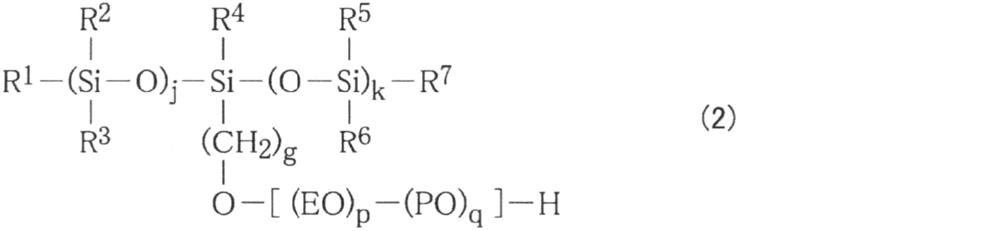
[式(2)中、R1、R2、R3、R4、R5、R6、及びR7は、各々独立して、炭素数が1~6のアルキル基、好ましくはメチル基を表す。j及びkは、各々独立して1以上の整数を表すが、好ましくは1~5、より好ましくは1~4、さらに好ましくは1又は2であり、j=k=1若しくはk=j+1を満足することが好ましい。また、gは0以上の整数を表し、好ましくは1~3であり、より好ましくは1である。さらに、p及びqはそれぞれ0以上の整数を表し、好ましくは1~5を表す。但しp+qは1以上の整数であり、好ましくはp+qは2~4である。]
式(2)で表されるシロキサン系界面活性剤としては、R1~R7がすべてメチル基を表し、jが1~2を表し、kが1~2を表し、gが1~2を表し、pが1以上5以下の整数を表し、qが0である化合物が好ましい。
[In formula (2), R 1 , R 2 , R 3 , R 4 , R 5 , R 6 and R 7 each independently represent an alkyl group having 1 to 6 carbon atoms, preferably a methyl group Represent. j and k each independently represent an integer of 1 or more, preferably 1 to 5, more preferably 1 to 4, still more preferably 1 or 2, and j = k = 1 or k = j + 1 is satisfied. It is preferable to do. Further, g represents an integer of 0 or more, preferably 1 to 3, and more preferably 1. Furthermore, p and q each represent an integer of 0 or more, preferably 1 to 5. However, p + q is an integer of 1 or more, preferably p + q is 2 to 4. ]
In the siloxane-based surfactant represented by the formula (2), R 1 to R 7 all represent a methyl group, j represents 1 to 2, k represents 1 to 2, and g is 1 to 2. A compound in which p is an integer of 1 or more and 5 or less and q is 0 is preferable.
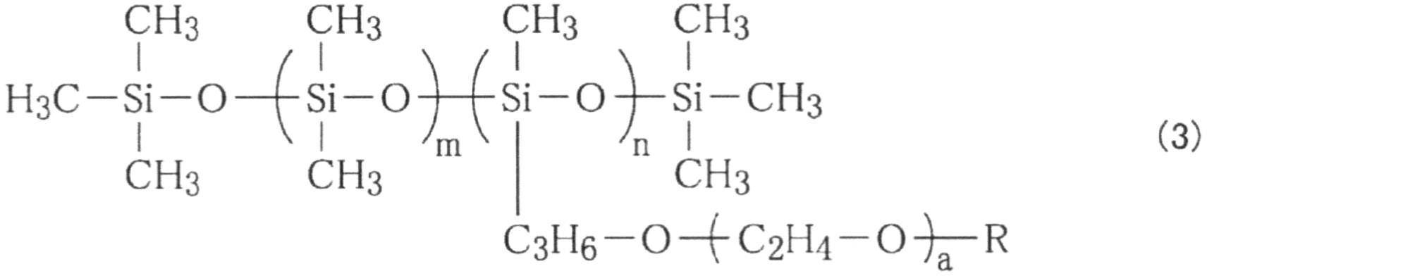
[式(3)中、Rは水素原子又はメチル基を表し、aは2~18の整数を表し、mは0~50の整数を表し、nは1~5の整数を表す。]
式(3)で表されるシロキサン系界面活性剤としては、特に限定されないが、例えば、Rが水素原子又はメチル基を表し、aが7~11の整数を表し、mが30~50の整数を表し、nが3~5の整数を表す化合物、Rが水素原子又はメチル基を表し、aが9~13の整数を表し、mが2~4の整数を表し、nが1~2の整数である化合物、Rが水素原子又はメチル基を表し、aが6~18の整数を表し、mが0の整数を表し、nが1の整数である化合物、Rが水素原子を表し、aが2~5の整数を表し、mが20~40の整数を表し、nが3~5の整数である化合物等が好ましい。
[In Formula (3), R represents a hydrogen atom or a methyl group, a represents an integer of 2 to 18, m represents an integer of 0 to 50, and n represents an integer of 1 to 5.] ]
The siloxane-based surfactant represented by the formula (3) is not particularly limited. For example, R represents a hydrogen atom or a methyl group, a represents an integer of 7 to 11, and m is an integer of 30 to 50 A compound in which n represents an integer of 3 to 5, R represents a hydrogen atom or a methyl group, a represents an integer of 9 to 13, m represents an integer of 2 to 4, and n is 1 to 2 A compound which is an integer, R is a hydrogen atom or a methyl group, a is an integer of 6 to 18, m is an integer of 0, n is an integer of 1, R is a hydrogen atom, a Preferred is a compound or the like in which is an integer of 2 to 5, m is an integer of 20 to 40, and n is an integer of 3 to 5.
シロキサン系界面活性剤は商業的に入手可能で、市販されているものを用いてもよく、例えば、オルフィンPD-501(日信化学工業株式会社製)、オルフィンPD-570(日信化学工業株式会社製)、BYK-347(ビックケミー株式会社製)、BYK-348(ビックケミー株式会社製)等を用いることができる。上記シロキサン系界面活性剤は、一種単独で用いても又は二種以上を併用してもよい。
Siloxane-based surfactants are commercially available and may be commercially available. For example, Olfin PD-501 (manufactured by Nisshin Chemical Industry Co., Ltd.), Olfin PD-570 (Nisshin Chemical Industry Co., Ltd.) Company made), BYK-347 (made by Bick Chemie, Inc.), BYK-348 (made by Bick Chemie, Inc.), etc. can be used. The above-mentioned siloxane type surfactant may be used alone or in combination of two or more.
フッ素系界面活性剤は、WO2010/050618及びWO2011/007888に開示されている通り、低吸収性、非吸収性の記録媒体に対して良好な濡れ性を奏する溶剤として知られている。フッ素系界面活性剤としては、特に限定されないが、目的に応じて適宜選択することができ、例えばパーフルオロアルキルスルホン酸塩、パーフルオロアルキルカルボン酸塩、パーフルオロアルキルリン酸エステル、パーフルオロアルキルエチレンオキサイド付加物、パーフルオロアルキルベタイン、パーフルオロアルキルアミンオキサイド化合物等が挙げられる。
As disclosed in WO 2010/050618 and WO 2011/07888, fluorinated surfactants are known as solvents that exhibit good wettability to low-absorbing non-absorbing recording media. The fluorine-based surfactant is not particularly limited, but can be appropriately selected depending on the purpose. For example, perfluoroalkyl sulfonate, perfluoroalkyl carboxylate, perfluoroalkyl phosphate, perfluoroalkyl ethylene Oxide adducts, perfluoroalkyl betaines, perfluoroalkylamine oxide compounds and the like can be mentioned.
上記以外にもフッ素系界面活性剤として、適宜合成したものを使用してもよいし、市販品を使用してもよい。市販品としては、例えばS・144、S・145(旭硝子株式会社製);FC・170C、FC・430、フロラード・FC4430(住友スリーエム株式会社製);FSO、FSO・100、FSN、FSN・100、FS・300(Dupont社製);FT・250、251(株式会社ネオス製)等が挙げられる。これらの中でも、Dupont社製のFSO、FSO・100、FSN、FSN・100、FS・300が好ましい。フッ素系界面活性剤は、一種単独で用いてもよいし、二種以上を併用してもよい。
In addition to the above, as the fluorine-based surfactant, one appropriately synthesized may be used, or a commercially available product may be used. Commercially available products include, for example, S.144, S.145 (Asahi Glass Co., Ltd.); FC.170C, FC.430, Florard.FC4430 (Sumitomo 3M Co., Ltd.); FSO, FSO.100, FSN, FSN.100 FS · 300 (manufactured by Dupont); FT · 250, 251 (manufactured by Neos Co., Ltd.) and the like. Among these, FSO manufactured by Dupont, FSO · 100, FSN, FSN · 100, FS · 300 are preferable. The fluorinated surfactants may be used alone or in combination of two or more.
また、液体噴射部15が噴射する液体が非水系インクである溶剤系インクである場合、吸収部材に含浸される含浸液は、例えば、下記一般式(I)で表される化合物、エステル類、及び二塩基酸エステル類からなる群より選択される少なくとも一種の有機溶剤(以下、「特定の有機溶剤」ともいう。)を含有することが好ましい。これらの特定の有機溶剤は、一種単独で用いてもよいし、2種以上を併用してもよい。
When the liquid jetted by the liquid jet unit 15 is a solvent-based ink which is a non-aqueous ink, the impregnating liquid impregnated in the absorbing member may be, for example, a compound represented by the following general formula (I), an ester, And at least one organic solvent selected from the group consisting of dibasic acid esters (hereinafter also referred to as “specific organic solvent”) is preferably contained. These specific organic solvents may be used alone or in combination of two or more.
特定の有機溶剤は、開口面15aに付着した非水系インクを溶解(軟化)させる作用に優れるので、非水系インクに含まれる成分が凝集してしまうことを抑制することにより、開口面15aの払拭効率が向上する。
Since the specific organic solvent is excellent in the function of dissolving (softening) the non-aqueous ink attached to the opening surface 15a, it is possible to wipe the opening surface 15a by suppressing aggregation of components contained in the non-aqueous ink. Efficiency is improved.
R1-O-(R2-O)n-R3 ・・・(I)
上記一般式(I)において、R1は、水素原子、アリール基または炭素数1以上6以下のアルキル基を表し、R2は、炭素数2以上4以下のアルキレン基を表し、R3は、アリール基または炭素数1以上6以下のアルキル基を表し、nは、1以上9以下の整数を表す。「アリール基」としては、例えば、フェニル基、ベンジル基、トリル基、キシリル基、ナフチル基、メチルナフチル基、ベンジルフェニル基、ビフェニル基等が挙げられる。また、「炭素数1以上6以下のアルキル基」としては、直鎖状または分岐状のアルキル基であることができ、例えば、メチル基、エチル基、n-プロピル基、iso-プロピル基、n-ブチル基、sec-ブチル基、tert-ブチル、ペンチル基またはヘキシル基等が挙げられる。「炭素数2以上4以下のアルキレン基」としては、例えば、エチレン基、n-プロピレン基、イソプロピレン基、またはブチレン基等が挙げられる。 R 1 -O- (R 2 -O) n -R 3 (I)
In the above general formula (I), R 1 represents a hydrogen atom, an aryl group or an alkyl group having 1 to 6 carbon atoms, R 2 represents an alkylene group having 2 to 4 carbon atoms, and R 3 represents Represents an aryl group or an alkyl group having 1 to 6 carbon atoms, n represents an integer of 1 to 9; Examples of the "aryl group" include phenyl group, benzyl group, tolyl group, xylyl group, naphthyl group, methylnaphthyl group, benzylphenyl group, biphenyl group and the like. The “alkyl group having 1 or more and 6 or less carbon atoms” may be a linear or branched alkyl group, and examples thereof include a methyl group, an ethyl group, an n-propyl group, an iso-propyl group, and an n -Butyl, sec-butyl, tert-butyl, pentyl or hexyl and the like. Examples of the “alkylene group having 2 to 4 carbon atoms” include ethylene group, n-propylene group, isopropylene group, and butylene group.
上記一般式(I)中、R1は、水素原子または炭素数2以上4以下のアルキル基であることが好ましい。また、上記一般式(I)中、R3は、炭素数2以上4以下のアルキル基であることが好ましい。これにより、非水系インクを溶解(軟化)させる作用が向上して、払拭効率が一層良好となる。
In the above general formula (I), R 1 is preferably a hydrogen atom or an alkyl group having 2 to 4 carbon atoms. In the above general formula (I), R 3 is preferably an alkyl group having 2 to 4 carbon atoms. Thereby, the action of dissolving (softening) the non-aqueous ink is improved, and the wiping efficiency is further improved.
上記一般式(I)中、nは、3以上6以下の整数であることが好ましい。これにより、非水系インクを溶解(軟化)させる作用が向上して、払拭効率が一層良好となる。
上記一般式(I)で表される化合物の具体例としては、アルキレングリコールモノエーテルや、アルキレングリコールジエーテル等のグリコールエーテル類が挙げられる。グリコールエーテル類は、1種単独か又は2種以上を混合して使用することができる。 In the above general formula (I), n is preferably an integer of 3 or more and 6 or less. Thereby, the action of dissolving (softening) the non-aqueous ink is improved, and the wiping efficiency is further improved.
Specific examples of the compound represented by the above general formula (I) include alkylene glycol monoethers and glycol ethers such as alkylene glycol diethers. The glycol ethers can be used singly or in combination of two or more.
アルキレングリコールモノエーテルとしては、例えば、エチレングリコールモノメチルエーテル、エチレングリコールモノエチルエーテル、エチレングリコールモノイソプロピルエーテル、エチレングリコールモノブチルエーテル、エチレングリコールモノヘキシルエーテル、エチレングリコールモノフェニルエーテル、ジエチレングリコールモノメチルエーテル、ジエチレングリコールモノエチルエーテル、ジエチレングリコールモノブチルエーテル、ジエチレングリコールモノヘキシルエーテル、ジエチレングリコールモノベンジルエーテル、トリエチレングリコールモノメチルエーテル、トリエチレングリコールモノエチルエーテル、トリエチレングリコールモノブチルエーテル、テトラエチレングリコールモノメチルエーテル、テトラエチレングリコールモノエチルエーテル、テトラエチレングリコールモノブチルエーテル、ペンタエチレングリコールモノメチルエーテル、ペンタエチレングリコールモノエチルエーテル、ペンタエチレングリコールモノブチルエーテル、プロピレングリコールモノメチルエーテル、プロピレングリコールモノエチルエーテル、ジプロピレングリコールモノメチルエーテル、ジプロピレングリコールモノエチルエーテル等が挙げられる。
As an alkylene glycol monoether, for example, ethylene glycol monomethyl ether, ethylene glycol monoethyl ether, ethylene glycol monoisopropyl ether, ethylene glycol monobutyl ether, ethylene glycol monohexyl ether, ethylene glycol monophenyl ether, diethylene glycol monomethyl ether, diethylene glycol monoethyl Ether, diethylene glycol monobutyl ether, diethylene glycol monohexyl ether, diethylene glycol monobenzyl ether, triethylene glycol monomethyl ether, triethylene glycol monoethyl ether, triethylene glycol monobutyl ether, tetraethylene glycol monomethyl ether, Laethylene glycol monoethyl ether, tetraethylene glycol monobutyl ether, pentaethylene glycol monomethyl ether, pentaethylene glycol monoethyl ether, pentaethylene glycol monobutyl ether, propylene glycol monomethyl ether, propylene glycol monoethyl ether, dipropylene glycol monomethyl ether Propylene glycol monoethyl ether etc. are mentioned.
アルキレングリコールジエーテルとしては、例えば、エチレングリコールジメチルエーテル、エチレングリコールジエチルエーテル、エチレングリコールジブチルエーテル、ジエチレングリコールジメチルエーテル、ジエチレングリコールジエチルエーテル、ジエチレングリコールエチルメチルエーテル、ジエチレングリコールジブチルエーテル、ジエチレングリコールブチルメチルエーテル、トリエチレングリコールジメチルエーテル、トリエチレングリコールジエチルエーテル、トリエチレングリコールジブチルエーテル、トリエチレングリコールブチルメチルエーテル、テトラエチレングリコールジメチルエーテル、テトラエチレングリコールジエチルエーテル、テトラエチレングリコールジブチルエーテル、プロピレングリコールジメチルエーテル、プロピレングリコールジエチルエーテル、ジプロピレングリコールジメチルエーテル、ジプロピレングリコールジエチルエーテル等が挙げられる。
As the alkylene glycol diether, for example, ethylene glycol dimethyl ether, ethylene glycol diethyl ether, ethylene glycol dibutyl ether, diethylene glycol dimethyl ether, diethylene glycol diethyl ether, diethylene glycol ethyl methyl ether, diethylene glycol dibutyl ether, diethylene glycol butyl methyl ether, triethylene glycol dimethyl ether, triethylene glycol Ethylene glycol diethyl ether, triethylene glycol dibutyl ether, triethylene glycol butyl methyl ether, tetra ethylene glycol dimethyl ether, tetra ethylene glycol diethyl ether, tetra ethylene glycol dibutyl ether, propylene glycol Methyl ether, propylene glycol diethyl ether, dipropylene glycol dimethyl ether, dipropylene glycol diethyl ether, and the like.
エステル類(R-CO-OR’)としては、例えば、Rが、水素原子、アルキル基、アリール基またはグリコールエーテル基であり、R’がアルキル基、アリール基である有機溶剤が挙げられる。このようなエステル類としては、グリコールエーテルエステル類を用いることが好ましく、例えば、エチレングリコールモノメチルエーテルアセテート、エチレングリコールモノエチルエーテルアセテート、エチレングリコールモノプロピルエーテルアセテート、エチレングリコールモノブチルエーテルアセテート、プロピレングリコールモノメチルエーテルアセテート、プロピレングリコールモノエチルエーテルアセテート、プロピレングリコールモノプロピルエーテルアセテート、プロピレングリコールモノブチルエーテルアセテート、ジメチレングリコールモノメチルエーテルアセテート、ジメチレングリコールモノエチルエーテルアセテート、ジメチレングリコールモノプロピルエーテルアセテート、ジメチレングリコールモノブチルエーテルアセテート、ジエチレングリコールモノメチルエーテルアセテート、ジエチレングリコールモノエチルエーテルアセテート、ジエチレングリコールモノプロピルエーテルアセテート、ジエチレングリコールモノブチルエーテルアセテート、ジプロピレングリコールモノメチルエーテルアセテート、ジプロピレングリコールモノエチルエーテルアセテート、ジプロピレングリコールモノプロピルエーテルアセテート、ジプロピレングリコールモノブチルエーテルアセテート、トリメチレングリコールモノメチルエーテルアセテート、トリメチレングリコールモノエチルエーテルアセテート、トリメチレングリコールモノプロピルエーテルアセテート、トリメチレングリコールモノブチルエーテルアセテート、トリエチレングリコールモノメチルエーテルアセテート、トリエチレングリコールモノエチルエーテルアセテート、トリエチレングリコールモノプロピルエーテルアセテート、トリエチレングリコールモノブチルエーテルアセテート、トリプロピレングリコールモノメチルエーテルアセテート、トリプロピレングリコールモノエチルエーテルアセテート、トリプロピレングリコールモノプロピルエーテルアセテート、トリプロピレングリコールモノブチルエーテルアセテート、3-メトキシブチルアセテート、3-メトキシ-3-メチル-1-ブチルアセテートなどが挙げられる。
Examples of the esters (R-CO-OR ') include organic solvents in which R is a hydrogen atom, an alkyl group, an aryl group or a glycol ether group, and R' is an alkyl group or an aryl group. As such esters, glycol ether esters are preferably used. For example, ethylene glycol monomethyl ether acetate, ethylene glycol monoethyl ether acetate, ethylene glycol monopropyl ether acetate, ethylene glycol monobutyl ether acetate, propylene glycol monomethyl ether Acetate, Propylene glycol monoethyl ether acetate, Propylene glycol monopropyl ether acetate, Propylene glycol monobutyl ether acetate, Dimethylene glycol monomethyl ether acetate, Dimethylene glycol monoethyl ether acetate, Dimethylene glycol monopropyl ether acetate, Dimethylene glycol monobutyl ether Ether acetate, diethylene glycol monomethyl ether acetate, diethylene glycol monoethyl ether acetate, diethylene glycol monopropyl ether acetate, diethylene glycol monobutyl ether acetate, dipropylene glycol monomethyl ether acetate, dipropylene glycol monoethyl ether acetate, dipropylene glycol monopropyl ether acetate, dipropylene Glycol monobutyl ether acetate, trimethylene glycol monomethyl ether acetate, trimethylene glycol monoethyl ether acetate, trimethylene glycol monopropyl ether acetate, trimethylene glycol monobutyl ether acetate, triethylene glycol Nomethyl ether acetate, triethylene glycol monoethyl ether acetate, triethylene glycol monopropyl ether acetate, triethylene glycol monobutyl ether acetate, tripropylene glycol monomethyl ether acetate, tripropylene glycol monoethyl ether acetate, tripropylene glycol monopropyl ether acetate And tripropylene glycol monobutyl ether acetate, 3-methoxybutyl acetate, 3-methoxy-3-methyl-1-butyl acetate and the like.
二塩基酸エステル類としては、ジカルボン酸(例えば、グルタル酸、アジピン酸、コハク酸等の脂肪族ジカルボン酸)のモノエステル、ジエステル等が挙げられる。具体的には、ジメチル-2-メチルグルタレート等が挙げられる。
Examples of dibasic acid esters include monoesters and diesters of dicarboxylic acids (for example, aliphatic dicarboxylic acids such as glutaric acid, adipic acid and succinic acid). Specifically, dimethyl-2-methylglutarate and the like can be mentioned.
上記の特定の有機溶剤の中でも、非水系インクを溶解(軟化)させる作用に優れているという点から、上記一般式(I)で表される化合物を用いることが好ましい。
上記の特定の有機溶剤には、標準沸点が170℃以上であるものを用いることが好ましく、標準沸点が250℃以上であるものを用いることがより好ましい。これにより、含浸液の乾燥に伴うノズル14の詰まりの発生を低減できるので、非水系インクの吐出安定性が良好となる。 Among the above-mentioned specific organic solvents, it is preferable to use a compound represented by the above general formula (I) from the viewpoint of being excellent in the action of dissolving (softening) the non-aqueous ink.
It is preferable to use what has a normal boiling point of 170 degreeC or more as said specific organic solvent, and it is more preferable to use what a normal boiling point is 250 degreeC or more. As a result, the occurrence of clogging of thenozzle 14 due to the drying of the impregnating liquid can be reduced, and therefore the ejection stability of the non-aqueous ink is improved.
上記の特定の有機溶剤には、標準沸点が170℃以上であるものを用いることが好ましく、標準沸点が250℃以上であるものを用いることがより好ましい。これにより、含浸液の乾燥に伴うノズル14の詰まりの発生を低減できるので、非水系インクの吐出安定性が良好となる。 Among the above-mentioned specific organic solvents, it is preferable to use a compound represented by the above general formula (I) from the viewpoint of being excellent in the action of dissolving (softening) the non-aqueous ink.
It is preferable to use what has a normal boiling point of 170 degreeC or more as said specific organic solvent, and it is more preferable to use what a normal boiling point is 250 degreeC or more. As a result, the occurrence of clogging of the
上記の特定の有機溶剤には、20℃における蒸気圧が1hPa以下であるものを用いることが好ましく、0.5hPa以下であるものを用いることがより好ましく、0.1hPa以下であるものを用いることがより一層好ましく、0.01hPa以下であるものを用いることが特に好ましい。これにより、含浸液の乾燥に伴うノズル14の詰まりの発生を低減できるので、非水系インクの吐出安定性が良好となる。
As the above-mentioned specific organic solvent, it is preferable to use one having a vapor pressure at 20 ° C. of 1 hPa or less, more preferably 0.5 hPa or less, and more preferably 0.1 hPa or less Is even more preferable, and it is particularly preferable to use one which is 0.01 hPa or less. As a result, the occurrence of clogging of the nozzle 14 due to the drying of the impregnating liquid can be reduced, and therefore the ejection stability of the non-aqueous ink is improved.
また、上記の特定の有機溶剤としては、20℃における表面張力が25mN/m以上35mN/m以下であるものを用いることが好ましい。これにより、後述する非水系インクとの相溶性が向上するので、払拭効率が一層向上する傾向にある。なお、表面張力の測定は、自動表面張力計CBVP-Z(協和界面科学社製)を用いて、20℃の環境下で白金プレートを有機溶剤で濡らしたときの表面張力を確認することにより測定することができる。
Moreover, it is preferable to use that whose surface tension in 20 degreeC is 25 mN / m or more and 35 mN / m or less as said specific organic solvent. As a result, the compatibility with the non-water-based ink described later is improved, and the wiping efficiency tends to be further improved. The surface tension is measured by using an automatic surface tension meter CBVP-Z (manufactured by Kyowa Interface Science Co., Ltd.) to confirm the surface tension when the platinum plate is wetted with an organic solvent under an environment of 20 ° C. can do.
特定の有機溶剤の含有量は、含浸液の全質量(100質量%)に対して、その下限値が30質量%以上であることが好ましく、50質量%以上であることがより好ましい。特定の有機溶剤の含有量が50質量%以上であることで、開口面15aの払拭効率が一層向上する。特定の有機溶剤の含浸液に対する含有量の上限は限られるものではなく100質量%でもよい。
The lower limit of the content of the specific organic solvent is preferably 30% by mass or more, and more preferably 50% by mass or more based on the total mass (100% by mass) of the impregnating solution. When the content of the specific organic solvent is 50% by mass or more, the wiping efficiency of the opening surface 15a is further improved. The upper limit of the content of the specific organic solvent to the impregnating solution is not limited and may be 100% by mass.
含浸液を保持させた吸収部材を用いてワイピングを行う場合には、吸収部材に含浸させた含浸液には、同吸収部材の質量100質量部に対して、10質量部以上の特定の有機溶剤が含まれていることが好ましく、15質量部以上であることがより好ましく、20質量部以上であることがより一層好ましく、40質量部以上であることがさらに好ましく、50質量部以上であることが特に好ましい。その上限値は、150質量部以下であることが好ましく、100質量部以下であることがより好ましい。10質量部以上であることで、開口面15aで固化したインクが溶解(軟化)しやすくなるので、払拭効率が一層向上する。150質量部以下であることで、吸収部材にインクが吸収されやすくなるので、インクの拭き残りによるノズル14の吐出異常や不吐出が生じにくくなり、インクの吐出安定性が良好となる。
When wiping is performed using an absorbing member holding an impregnating solution, the impregnating solution impregnated in the absorbing member contains 10 parts by mass or more of a specific organic solvent based on 100 parts by mass of the absorbing member. Is preferably contained, more preferably 15 parts by mass or more, still more preferably 20 parts by mass or more, still more preferably 40 parts by mass or more, and 50 parts by mass or more. Is particularly preferred. The upper limit thereof is preferably 150 parts by mass or less, and more preferably 100 parts by mass or less. When the content is 10 parts by mass or more, the ink solidified on the opening surface 15 a is easily dissolved (softened), and the wiping efficiency is further improved. When the amount is 150 parts by mass or less, since the ink is easily absorbed by the absorbing member, ejection failure or non-ejection of the nozzle 14 due to the remaining ink after wiping does not easily occur, and the ejection stability of the ink is improved.
また、液体噴射部15が噴射する液体が溶剤系インクで有る場合に吸収部材に含浸される含浸液は、上記の特定の有機溶剤以外の有機溶剤を含有してもよいし、さらに、界面活性剤、pH調整剤、キレート化剤、防腐剤、防かび剤及び防錆剤など、所定の性能を付与するための物質を含有してもよい。
In addition, when the liquid jetted by the liquid jet unit 15 is a solvent-based ink, the impregnating liquid impregnated in the absorbing member may contain an organic solvent other than the above specific organic solvent, and further, the surface activity You may contain the substance for providing predetermined | prescribed performance, such as an agent, a pH adjuster, a chelating agent, antiseptic | preservative, a fungicide, and a rust preventive agent.
図1に示すように、メンテナンス装置16は、メンテナンス部材21を有するメンテナンスユニット22(図2参照)が着脱自在に装着される箱体状の装着部23と、装着部23をガイドフレーム24に沿って移動方向Xに往復移動させる駆動機構25と、を備える。
As shown in FIG. 1, the maintenance device 16 has a box-like mounting portion 23 on which a maintenance unit 22 (see FIG. 2) having a maintenance member 21 is detachably mounted, and the mounting portion 23 along the guide frame 24. And a drive mechanism 25 that reciprocates in the moving direction X.
図2に示すように、メンテナンスユニット22は、収容部26内においてメンテナンス部材21を移動可能な状態で保持する保持部27と、保持部27を収容する収容部26と、メンテナンス部材21に関する情報を記憶する記憶媒体28と、を備える。メンテナンスユニット22が装着部23に装着された状態では、収容部26の天面26tが液体噴射部15に向かって露出する。
As shown in FIG. 2, the maintenance unit 22 holds information on the holding portion 27 which holds the maintenance member 21 in the movable state in the holding portion 26, the holding portion 26 which holds the holding portion 27, and information on the maintenance member 21. And a storage medium 28 for storing. When the maintenance unit 22 is attached to the attachment unit 23, the top surface 26 t of the accommodation unit 26 is exposed toward the liquid ejecting unit 15.
装着部23内には、装着部23に装着されたメンテナンスユニット22の記憶媒体28の接続部に接触可能な位置に、板ばね等からなる接続端子38が配置されている。接続端子38は制御部20(図1参照)と電気的に接続されている。そして、接続端子38が装着部23に装着されたメンテナンスユニット22の記憶媒体28の接続部と接触した場合には、制御部20が接続端子38を介して記憶媒体28が記憶する情報を読み出したり、記憶媒体28に情報を書き込んだりする。
In the mounting portion 23, a connection terminal 38 formed of a plate spring or the like is disposed at a position where it can contact the connection portion of the storage medium 28 of the maintenance unit 22 mounted on the mounting portion 23. The connection terminal 38 is electrically connected to the control unit 20 (see FIG. 1). When the connection terminal 38 comes in contact with the connection portion of the storage medium 28 of the maintenance unit 22 mounted on the mounting unit 23, the control unit 20 reads the information stored in the storage medium 28 via the connection terminal 38. , Write information to the storage medium 28.
収容部26の天面26tには開口部29が設けられ、この開口部29を通じてメンテナンス部材21の一部が露出する。以降の説明において、この開口部29から露出したメンテナンス部材21の部分を払拭部31という。
An opening 29 is provided on the top surface 26 t of the housing 26, and a part of the maintenance member 21 is exposed through the opening 29. In the following description, the portion of the maintenance member 21 exposed from the opening 29 is referred to as the wiping unit 31.
保持部27は、メンテナンス部材21の基端側部分が巻かれた繰出ローラー32と、繰出ローラー32の回転に伴って巻き出されるメンテナンス部材21の先端側部分を巻き取る巻取ローラー33と、繰出ローラー32と巻取ローラー33の間に位置するメンテナンス部材21が巻き掛けられる複数の巻掛ローラー34,35,36,37と、を備える。巻掛ローラー34,35,36,37は、繰出ローラー32と巻取ローラー33の間に位置するメンテナンス部材21に張力を付与するとともに、その帳設方向を変更するものであり、その数や配置は任意に変更することができる。
The holding unit 27 includes a delivery roller 32 around which the base end side portion of the maintenance member 21 is wound, a take-up roller 33 for taking up the tip side portion of the maintenance member 21 that is unwound along with the rotation of the delivery roller 32 A plurality of winding rollers 34, 35, 36, 37 on which the maintenance member 21 positioned between the roller 32 and the winding roller 33 is wound. The winding rollers 34, 35, 36, 37 apply tension to the maintenance member 21 positioned between the feeding roller 32 and the winding roller 33, and change the direction in which they are laid out. Can be changed arbitrarily.
巻掛ローラー34,35,36,37のうちの1つである巻掛ローラー36は、収容部26の開口部29からその周面の一部が突出するように配置される。そのため、メンテナンス部材21において巻掛ローラー36に巻き掛けられた部分が払拭部31となる。そして、繰出ローラー32及び巻取ローラー33の回転に伴ってメンテナンス部材21が移動することにより、開口部29に配置される払拭部31が順次未使用の部分に変更される。
The winding roller 36 which is one of the winding rollers 34, 35, 36, 37 is disposed such that a part of the circumferential surface thereof protrudes from the opening 29 of the housing portion 26. Therefore, the portion wound around the winding roller 36 in the maintenance member 21 becomes the wiping unit 31. Then, the maintenance member 21 is moved along with the rotation of the feeding roller 32 and the winding roller 33, whereby the wiping portion 31 disposed in the opening 29 is sequentially changed to an unused portion.
また、繰出ローラー32及び巻取ローラー33の回転に伴ってメンテナンス部材21が移動する結果、メンテナンス部材21がそれ以上巻き出せなくなった場合には、そのメンテナンスユニット22は使用により消費されたものとして、新しいものに交換される。すなわち、使用済みのメンテナンスユニット22が装着部23から取り外され、別の使用済みでないメンテナンスユニット22が装着部23に装着される。
In addition, as a result of the maintenance member 21 moving as a result of the rotation of the feeding roller 32 and the winding roller 33, when the maintenance member 21 can not unwind further, the maintenance unit 22 is consumed as it is used, It is exchanged for a new one. That is, the used maintenance unit 22 is removed from the mounting unit 23, and another unused maintenance unit 22 is mounted to the mounting unit 23.
図3及び図4に示すように、メンテナンスユニット22において収容部26は移動方向Xが長手方向となり、払拭部31及び開口部29は、収容部26の長手方向における中央付近に、搬送方向Yが長手方向となるように配置される。
As shown in FIG. 3 and FIG. 4, in the maintenance unit 22, the moving direction X of the accommodation portion 26 in the moving direction X is the longitudinal direction, and the wiping direction 31 is in the vicinity of the center in the longitudinal direction of the accommodation portion 26. It is arranged to be in the longitudinal direction.
本実施形態において、収容部26において開口部29よりも長手方向の一端側(天面26tに三角マークのある側)を先端側、開口部29よりも長手方向の他端側(天面26tが湾曲面になっている側)を基端側という。また、収容部26において天面26tと交差する先端の面を先端面26f、天面26tと交差する基端の面を基端面26rといい、さらに天面26t、先端面26f及び基端面26rと交差する面を側面26sという。
In the present embodiment, one end side of the accommodation portion 26 in the longitudinal direction than the opening 29 (the side having a triangle mark on the top surface 26t) is a tip end side, and the other end side in the longitudinal direction than the opening 29 (the top surface 26t is The side which is a curved surface is called the proximal side. Further, in the accommodation portion 26, the surface of the tip intersecting with the top surface 26t is referred to as a tip end surface 26f, and the surface of the base end intersecting with the top surface 26t is referred to as a base end surface 26r, and further, the top surface 26t, the tip surface 26f and the base end surface 26r The intersecting surfaces are called side surfaces 26s.
一方、装着部23において、メンテナンスユニット22を装着した場合に先端面26fと対向する壁部を前壁23f、基端面26rと対向する壁部を後壁23r、側面26sと対向する壁部を側壁23sという。
On the other hand, in the mounting portion 23, when the maintenance unit 22 is mounted, the wall facing the front end face 26f is a front wall 23f, the wall facing the base end face 26r is a rear wall 23r, and the wall facing the side 26s is a side wall It is called 23s.
収容部26の基端面26rにおける下方寄りの位置には、上端側が収容部26に対する固定端となる一方で下端側が自由端となる弾性片部41が設けられる。弾性片部41は、上端側の固定端を支点として移動方向Xに弾性変形可能である。そして、弾性片部41において自由端となる下端には係止爪42が外方に向けて突設される。
An elastic piece portion 41 whose upper end side is a fixed end to the accommodation portion 26 and whose lower end side is a free end is provided at a lower position of the base end surface 26 r of the accommodation portion 26. The elastic piece portion 41 is elastically deformable in the moving direction X with the fixed end on the upper end side as a fulcrum. Then, at the lower end which is a free end in the elastic piece portion 41, a locking claw 42 is protruded outward.
一方、装着部23の後壁23rにおける下方寄りの位置には、弾性片部41の係止爪42が係合可能な掛止孔52が形成される。そして、メンテナンスユニット22を装着部23に対して装着した場合には、メンテナンスユニット22の係止爪42が装着部23の掛止孔52に対して係止されることにより、メンテナンスユニット22の装着部23からの脱落が抑制される。
On the other hand, a locking hole 52 to which the locking claw 42 of the elastic piece 41 can be engaged is formed at a lower position on the rear wall 23r of the mounting portion 23. When the maintenance unit 22 is mounted to the mounting portion 23, the locking claws 42 of the maintenance unit 22 are locked to the locking holes 52 of the mounting portion 23 to mount the maintenance unit 22. Dropout from the part 23 is suppressed.
収容部26の先端面26fにおける上端には、基端から先端に向かう方向に天面26tから突出する指掛部43が突設される。指掛部43は、メンテナンスユニット22を装着部23から取り外す際に、使用者が指先を引っ掛けるためのものである。
At the upper end of the distal end surface 26f of the housing portion 26, a finger hook 43 projecting from the top surface 26t in a direction from the base end to the distal end is provided in a protruding manner. The finger hook portion 43 is for the user to hook a fingertip when removing the maintenance unit 22 from the mounting portion 23.
一方、装着部23の前壁23fにおける上端には、切り欠き部53が形成される。そして、メンテナンスユニット22を装着部23に対して装着した場合には、メンテナンスユニット22の指掛部43が切り欠き部53を通じて装着部23の外側に露出する(図2参照)。
On the other hand, a notch 53 is formed at the upper end of the front wall 23 f of the mounting portion 23. Then, when the maintenance unit 22 is mounted to the mounting portion 23, the finger hook portion 43 of the maintenance unit 22 is exposed to the outside of the mounting portion 23 through the cutout portion 53 (see FIG. 2).
収容部26の両側面26sにおいて、長手方向の中央よりもやや先端よりの位置であって、上下方向(噴射方向Z)の略中央付近となる位置には、略円柱状をなす係合突起44が突設される。
On both side surfaces 26s of the housing portion 26, the engagement protrusion 44 having a substantially cylindrical shape is at a position slightly closer to the tip than the center in the longitudinal direction and near the approximate center in the vertical direction (the injection direction Z). Is projected.
一方、装着部23の両側壁23sの内側部分には、長手方向の中央よりもやや先端よりの位置に、上端から下方に向けて上下方向の中央付近まで延びる案内溝54が設けられる。案内溝54において上端の開口の幅は、係合突起44の直径よりも若干大きく設定されるとともに、その溝幅は下方に向かうに連れて次第に幅狭となることが好ましい。そして、メンテナンスユニット22を装着部23に対して装着する際には、メンテナンスユニット22の係合突起44が案内溝54に案内されることで、メンテナンスユニット22が装着部23内の適切な位置に収容される。
On the other hand, a guide groove 54 extending downward from the upper end to the vicinity of the center in the vertical direction is provided in the inside portion of both side walls 23s of the mounting portion 23 at a position slightly closer to the tip than the center in the longitudinal direction. The width of the opening at the upper end of the guide groove 54 is preferably set to be slightly larger than the diameter of the engagement protrusion 44, and the groove width is preferably narrowed gradually toward the lower side. Then, when mounting the maintenance unit 22 to the mounting portion 23, the engaging projection 44 of the maintenance unit 22 is guided by the guide groove 54, whereby the maintenance unit 22 is positioned at an appropriate position in the mounting portion 23. Be housed.
次に、メンテナンス装置16のメンテナンス動作であるワイピングについて説明する。
液体噴射装置11において、印刷のためのノズル14から規定サイズの液滴を噴射すると、その液滴よりも微小な液滴からなるミストが副次的に生じてしまう。こうしたミストがノズル14の周辺に付着して徐々に大きくなって液滴となると、この大きくなった液滴がノズル14から噴射される液滴に接触することにより、噴射された液滴の飛翔方向を変化させ、印刷品質を低下させてしまうことがある。 Next, wiping which is a maintenance operation of themaintenance device 16 will be described.
In theliquid ejecting apparatus 11, when droplets of a prescribed size are ejected from the nozzle 14 for printing, mist consisting of droplets smaller than the droplets is generated as a subsidiary. When such mist adheres to the periphery of the nozzle 14 and gradually increases to become droplets, the enlarged droplets come in contact with the droplets ejected from the nozzle 14 so that the flying direction of the ejected droplets Change the print quality and may reduce the print quality.
液体噴射装置11において、印刷のためのノズル14から規定サイズの液滴を噴射すると、その液滴よりも微小な液滴からなるミストが副次的に生じてしまう。こうしたミストがノズル14の周辺に付着して徐々に大きくなって液滴となると、この大きくなった液滴がノズル14から噴射される液滴に接触することにより、噴射された液滴の飛翔方向を変化させ、印刷品質を低下させてしまうことがある。 Next, wiping which is a maintenance operation of the
In the
そこで、例えば所定枚数あるいは所定時間の印刷を行った場合には、キャリッジ18がメンテナンス領域に移動して、メンテナンス装置16がメンテナンス部材21を使用したワイピングを行う。具体的には、駆動機構25の駆動によって、メンテナンスユニット22が装着された装着部23が移動方向Xに沿って移動することによって、払拭部31で液体噴射部15の開口面15aを払拭する(図2参照)。
Therefore, for example, when printing is performed for a predetermined number of sheets or for a predetermined time, the carriage 18 moves to the maintenance area, and the maintenance device 16 performs wiping using the maintenance member 21. Specifically, when the mounting unit 23 to which the maintenance unit 22 is mounted moves along the moving direction X by driving of the driving mechanism 25, the wiping unit 31 wipes the opening surface 15 a of the liquid ejecting unit 15 (see FIG. See Figure 2).
なお、液体噴射装置11において、キャリッジ18をメンテナンス領域に移動させて、液体噴射部15のノズル14からメンテナンス動作として液体を排出する排出動作を実行した場合、ノズル14から排出した液体が開口面15aに付着してしまうことがある。このような場合にも、メンテナンス装置16が上述したメンテナンス部材21を使用したワイピングを行う。
In the liquid ejecting apparatus 11, when the carriage 18 is moved to the maintenance area and the discharging operation of discharging the liquid from the nozzle 14 of the liquid ejecting unit 15 is performed as the maintenance operation, the liquid discharged from the nozzle 14 is the opening surface 15a. It may stick to the Also in such a case, the maintenance device 16 performs the wiping using the maintenance member 21 described above.
これにより、液体噴射部15に付着していたミストや、液体の排出動作に伴って開口面15aに付着した液体がメンテナンス部材21によって吸収されるとともに、液体噴射部15に付着していた紙粉などの異物がメンテナンス部材21によって拭き取られる。また、液体噴射部15の払拭が終了すると、繰出ローラー32及び巻取ローラー33が回転してメンテナンス部材21を移動させ、開口部29から露出する払拭部31を未使用の部分に変更する。
Thus, the maintenance member 21 absorbs the mist attached to the liquid ejecting unit 15 and the liquid attached to the opening surface 15 a as the liquid is discharged, and the paper dust adhering to the liquid ejecting unit 15 And the like are wiped off by the maintenance member 21. When the wiping of the liquid ejecting unit 15 is completed, the feeding roller 32 and the winding roller 33 rotate to move the maintenance member 21 and change the wiping unit 31 exposed from the opening 29 to an unused portion.
なお、装着部23が移動方向Xに沿って移動して払拭部31が液体噴射部15に接触しているときに、繰出ローラー32及び巻取ローラー33が回転してメンテナンス部材21を移動させるようにすれば、払拭部31による払拭性能を向上させることができる。
The feeding roller 32 and the winding roller 33 rotate to move the maintenance member 21 when the mounting unit 23 moves along the moving direction X and the wiping unit 31 is in contact with the liquid ejecting unit 15. In this case, the wiping performance of the wiping unit 31 can be improved.
次に、記憶媒体28が記憶する情報について説明する。
記憶媒体28は、以下に挙げる情報のうち、少なくとも1つを記憶する。
(1)メンテナンス部材21を使用して行われたメンテナンスの実行回数に対応する値。 Next, information stored in thestorage medium 28 will be described.
Thestorage medium 28 stores at least one of the information listed below.
(1) A value corresponding to the number of times of maintenance performed using themaintenance member 21.
記憶媒体28は、以下に挙げる情報のうち、少なくとも1つを記憶する。
(1)メンテナンス部材21を使用して行われたメンテナンスの実行回数に対応する値。 Next, information stored in the
The
(1) A value corresponding to the number of times of maintenance performed using the
(2)液体噴射部15のメンテナンスに伴うメンテナンス部材21の移動量に対応する値。
(3)メンテナンスユニット22が装着された液体噴射装置に関する情報。 (2) A value corresponding to the movement amount of themaintenance member 21 associated with the maintenance of the liquid ejecting unit 15.
(3) Information on the liquid ejecting apparatus on which themaintenance unit 22 is mounted.
(3)メンテナンスユニット22が装着された液体噴射装置に関する情報。 (2) A value corresponding to the movement amount of the
(3) Information on the liquid ejecting apparatus on which the
(4)メンテナンスユニット22が液体噴射装置に装着された日に関する情報。
(5)メンテナンスユニット22の製造日に関する情報。
(6)メンテナンスユニット22を装着可能な液体噴射装置に関する情報。 (4) Information on the day when themaintenance unit 22 was attached to the liquid ejecting apparatus.
(5) Information on the manufacturing date of themaintenance unit 22.
(6) Information on the liquid ejecting apparatus to which themaintenance unit 22 can be attached.
(5)メンテナンスユニット22の製造日に関する情報。
(6)メンテナンスユニット22を装着可能な液体噴射装置に関する情報。 (4) Information on the day when the
(5) Information on the manufacturing date of the
(6) Information on the liquid ejecting apparatus to which the
(7)メンテナンス部材21に含浸される液体に関する情報。
以下に、上記各情報について説明する。
(1)は、メンテナンス部材21の使用履歴に関する情報であり、例えば、ワイピングを実行した回数の累積値である。あるいは、メンテナンスユニット22に使用不能になるまでに実行可能なメンテナンスの回数が寿命回数として設定されている場合には、その寿命回数に対する実行回数の割合や、寿命回数までの残り回数などであってもよい。 (7) Information on the liquid impregnated in themaintenance member 21.
Below, each said information is demonstrated.
(1) is information on the use history of themaintenance member 21 and is, for example, an accumulated value of the number of times the wiping is performed. Alternatively, if the number of maintenances that can be performed before the maintenance unit 22 becomes unusable is set as the number of lifetimes, the ratio of the number of executions to the number of lifetimes, the number of remaining times until the number of lifetimes, etc. It is also good.
以下に、上記各情報について説明する。
(1)は、メンテナンス部材21の使用履歴に関する情報であり、例えば、ワイピングを実行した回数の累積値である。あるいは、メンテナンスユニット22に使用不能になるまでに実行可能なメンテナンスの回数が寿命回数として設定されている場合には、その寿命回数に対する実行回数の割合や、寿命回数までの残り回数などであってもよい。 (7) Information on the liquid impregnated in the
Below, each said information is demonstrated.
(1) is information on the use history of the
(2)は、メンテナンス部材21の使用履歴に関する情報であり、例えば、ワイピングに伴ってメンテナンス部材21を移動させた回数や繰出ローラー32または巻取ローラー33の回転数、所定の測定位置を通過するメンテナンス部材21の長さなどの累積値である。あるいは、メンテナンス部材21の全長に対する移動距離の割合や、未使用部分の残り長さ、メンテナンス部材21の全長に対する未使用部分の残り長さの割合などであってもよい。
(2) is information on the use history of the maintenance member 21. For example, the number of times the maintenance member 21 is moved with wiping, the number of rotations of the feeding roller 32 or the winding roller 33, and a predetermined measurement position It is a cumulative value of the length of the maintenance member 21 or the like. Alternatively, the ratio of the movement distance to the total length of the maintenance member 21, the remaining length of the unused portion, the ratio of the remaining length of the unused portion to the total length of the maintenance member 21, or the like may be used.
(3)は、メンテナンス部材21の使用履歴に関する情報であり、特に、1つのメンテナンスユニット22を複数の異なる液体噴射装置の間で使い回す場合に、記憶媒体28が記憶することが好ましい情報である。そして、記憶媒体28は、1つのメンテナンスユニット22が液体噴射装置に装着される都度、その装着された液体噴射装置の種類やその液体噴射装置が噴射する液体の種類を特定する情報を、メンテナンスユニット22が装着された液体噴射装置に関する情報として記憶する。
(3) is information on the use history of the maintenance member 21. In particular, it is preferable that the storage medium 28 store information when one maintenance unit 22 is used among a plurality of different liquid ejecting apparatuses. . Then, each time the maintenance unit 22 is attached to the liquid ejecting apparatus, the storage medium 28 is a maintenance unit that specifies the type of the attached liquid ejecting apparatus and the type of liquid ejected by the liquid ejecting apparatus. The information 22 is stored as information on the attached liquid ejecting apparatus.
(4)は、メンテナンス部材21の使用履歴に関する情報であり、例えば、メンテナンスユニット22が液体噴射装置に最初に装着された日であってもよいし、そのメンテナンスユニット22に使用期限が設定されている場合には、メンテナンスユニット22が液体噴射装置に最初に装着されてから使用期限までの残り日数であってもよい。
(4) is information on the use history of the maintenance member 21. For example, the day when the maintenance unit 22 is first attached to the liquid ejecting apparatus may be used, or the maintenance unit 22 has its expiration date set. In the case where the maintenance unit 22 is first attached to the liquid ejecting apparatus, it may be the remaining number of days until the expiration date.
(5)は、メンテナンスユニット22の製造日であってもよいし、そのメンテナンスユニット22に使用期限が設定されている場合には、製造日から使用期限までの残り日数であってもよい。
(5) may be the manufacturing date of the maintenance unit 22, or when the expiration date is set in the maintenance unit 22, it may be the remaining number of days from the manufacturing date to the expiration date.
(6)は、特に、メンテナンス部材21の素材や、吸収部材であるメンテナンス部材21に含浸される含浸液の種類等によって、特定の液体噴射部に対して使用することが適切でない場合などに、噴射する液体や含浸液、あるいは液体噴射装置の種類等として記憶媒体28が記憶することが好ましい。
(6) is particularly suitable when it is not suitable to use for a specific liquid ejecting unit, depending on the material of the maintenance member 21, the kind of the impregnating solution to be impregnated into the maintenance member 21 which is the absorption member, etc. It is preferable that the storage medium 28 store data as the liquid to be jetted, the impregnating liquid, or the type of the liquid jet apparatus.
特に、含浸液は、液体噴射部15が噴射する液体に適した性質のものが選択されるため、こうした含浸液が別の種類の液体を噴射する液体噴射部15に付着することは好ましくない。例えば、含浸液の組成は、使用されるインクの組成に合わせて最適設計されるため、組合せが想定されていないインクを使用する液体噴射部15に、使用歴のあるメンテナンス部材21を介して相性の悪い含浸液が付着すると、その含浸液に接触したインクから異物が析出することがある。
In particular, since the impregnating liquid is selected to have a property suitable for the liquid jetted by the liquid jet unit 15, it is not preferable that such an impregnating liquid adheres to the liquid jet unit 15 which jets another type of liquid. For example, since the composition of the impregnating liquid is optimally designed in accordance with the composition of the ink to be used, the compatibility with the liquid jet unit 15 using ink whose combination is not supposed is through the maintenance member 21 having a history of use When the impregnation solution of the above is attached, foreign matter may precipitate from the ink in contact with the impregnation solution.
すると、析出した異物が開口面15aに固着して拭き取れなくなったり、析出した異物が付着した状態の開口面15aをワイピングすることにより、開口面15aの撥水膜を傷つけたりするおそれがある。特に、顔料インクに使用される顔料は、その溶媒の種類(水系であるか有機溶剤系であるか)によってそれぞれ安定して分散するものが用いられているので、異なる種類の溶媒と混合されると、顔料が析出したり固化したりして異物が発生しやすい。
Then, the deposited foreign matter may be fixed to the opening face 15a and not wiped off, or the water repellent film of the opening face 15a may be damaged by wiping the opening face 15a in the state where the deposited foreign matter is attached. In particular, the pigments used in the pigment ink are those which are respectively dispersed stably depending on the type of the solvent (whether it is aqueous or organic solvent type), so they are mixed with different types of solvents In addition, the pigment is likely to precipitate or solidify to generate foreign matter.
(7)は、(6)で記述したように、メンテナンス部材21に含浸された含浸液を、特定の液体噴射部15に対して使用することが適切でない場合に、記憶媒体28が記憶することが好ましい。また、メンテナンス部材21に含浸された液体の蒸発のしやすさや性状の変化のしやすさなどに基づいて、メンテナンスユニット22の使用期限や寿命回数が設定されている場合には、その使用期限までの残り日数や残り回数を記憶媒体28が記憶するようにしてもよい。また、メンテナンス部材21に含浸液が含浸されていない場合には、含浸液が含浸されていないことを、メンテナンス部材に含浸される液体に関する情報として、記憶媒体28が記憶するようにしてもよい。
In (7), as described in (6), the storage medium 28 stores when it is not appropriate to use the impregnating solution impregnated in the maintenance member 21 for the specific liquid ejecting unit 15. Is preferred. In addition, when the expiration date and the number of lifetimes of the maintenance unit 22 are set based on the ease of evaporation of the liquid impregnated in the maintenance member 21 and the ease of change of the property, etc. The storage medium 28 may store the number of days remaining and the number of times remaining. Further, when the maintenance member 21 is not impregnated with the impregnating solution, the storage medium 28 may store that the impregnating solution is not impregnated, as information on the liquid to be impregnated into the maintenance member.
次に、制御部20によるメンテナンス装置16の制御について説明する。
制御部20は、メンテナンスユニット22が備える記憶媒体28が記憶した上記各種情報に基づいて、メンテナンス装置16等の制御を行う。 Next, control of themaintenance device 16 by the control unit 20 will be described.
Thecontrol unit 20 controls the maintenance device 16 and the like based on the various information stored in the storage medium 28 included in the maintenance unit 22.
制御部20は、メンテナンスユニット22が備える記憶媒体28が記憶した上記各種情報に基づいて、メンテナンス装置16等の制御を行う。 Next, control of the
The
例えば、メンテナンスユニット22が装着部23に装着されると、制御部20は、接続端子38に接続された記憶媒体28から上記(1)~(7)の情報を読み出す。そして、(4)の装着日や(5)の製造日に対して使用期限が経過していた場合や、装着された液体噴射装置11の種類等が、(6)の装着可能な液体噴射装置の種類等に該当しなかった場合や、(7)の含浸液に適さない種類等であった場合などには、その旨を表示部55に表示するなどして、使用者に報知する。
For example, when the maintenance unit 22 is attached to the attachment unit 23, the control unit 20 reads out the information (1) to (7) from the storage medium 28 connected to the connection terminal 38. Then, when the expiration date has passed with respect to the mounting date of (4) or the manufacturing date of (5), the type of the liquid ejecting apparatus 11 mounted, etc., can be mounted on the liquid ejecting apparatus of (6) When it does not correspond to the type etc., or when it is the type etc. not suitable for the impregnating liquid of (7), the user is notified by displaying that fact on the display unit 55 or the like.
また、制御部20は、(1),(2)の情報に基づいて、メンテナンスユニット22の寿命回数までの残り回数やメンテナンス部材21の未使用部分の残り長さを把握する。そして、寿命回数までの残り回数が0である場合や、メンテナンス部材21の未使用部分の残り長さが一回分のワイピングに不足する場合などには、表示部55などを通じてエラー表示をする。
Further, the control unit 20 grasps the remaining number of times until the number of lifetimes of the maintenance unit 22 and the remaining length of the unused portion of the maintenance member 21 based on the information of (1) and (2). If the remaining number of times until the number of lifetimes is 0, or if the remaining length of the unused portion of the maintenance member 21 is insufficient for wiping for one time, an error is displayed through the display unit 55 or the like.
なお、メンテナンス動作の実行後に、寿命回数までの残り回数が0に近くなったり、メンテナンス部材21の未使用部分の残り長さが残りわずかになったりした場合に、表示部55などを通じてその旨を警告するようにしてもよい。また、制御部20は、メンテナンスユニット22が装着部23に装着されている間に、その使用期限や寿命回数に到達した場合にも、その旨を表示部55に表示するなどして、使用者に報知する事が好ましい。
If, after the maintenance operation, the number of remaining times until the number of service life becomes close to 0 or the remaining length of the unused portion of the maintenance member 21 becomes slightly small, this is indicated through the display unit 55 etc. You may be warned. Also, when the maintenance unit 22 is mounted on the mounting unit 23, the control unit 20 also displays the fact on the display unit 55 when the expiration date or the number of times of use is reached. It is preferable to notify to
さらに、制御部20は、接続端子38に接続された記憶媒体28に、(3)の情報として、実際に装着された液体噴射装置11等の情報を書き込む。また、すでに記憶媒体28に(3)の情報が書き込まれている場合には、その情報を読み出し、その過去に装着された液体噴射装置と現在装着されている液体噴射装置11とで、上述したように使用している液体や含浸液の相性が悪い場合などには、表示部55などを通じてエラー表示をする。
Further, the control unit 20 writes information of the liquid ejecting apparatus 11 or the like actually mounted on the storage medium 28 connected to the connection terminal 38 as the information of (3). Further, when the information of (3) is already written in the storage medium 28, the information is read, and the liquid ejecting apparatus mounted in the past and the liquid ejecting apparatus 11 currently mounted are described above. When the compatibility of the liquid or the impregnating solution being used is not good, an error is displayed through the display unit 55 or the like.
制御部20は、(1)~(7)の情報に基づいて、次のワイピングを実行可能であると判断した場合には、メンテナンス装置16によるメンテナンス動作を許容する。そしてメンテナンス装置16によるワイピングが実行された場合には、その実行回数や使用量を記憶媒体28に記憶させる。
When the control unit 20 determines that the next wiping can be performed based on the information of (1) to (7), the control unit 20 allows the maintenance operation by the maintenance device 16. When the wiping by the maintenance device 16 is executed, the number of times of execution and the amount used are stored in the storage medium 28.
次に、以上のように構成された液体噴射装置11の作用について説明する。
例えば、メンテナンス動作の実行に先だって、制御部20が記憶媒体28に記憶された(1)の情報を確認することにより、連続的に実行される印刷処理の間にワイピングを複数回実施する場合などに、その印刷処理の途中にワイピングの寿命回数に達して、印刷処理が途中で中断されてしまう、という事態を回避することが可能になる。 Next, the operation of theliquid ejecting apparatus 11 configured as described above will be described.
For example, when thecontrol unit 20 checks the information (1) stored in the storage medium 28 prior to the execution of the maintenance operation, wiping may be performed a plurality of times between printing processes that are continuously performed, etc. In addition, it is possible to avoid the situation in which the printing process is interrupted midway by reaching the wiping life count in the middle of the printing process.
例えば、メンテナンス動作の実行に先だって、制御部20が記憶媒体28に記憶された(1)の情報を確認することにより、連続的に実行される印刷処理の間にワイピングを複数回実施する場合などに、その印刷処理の途中にワイピングの寿命回数に達して、印刷処理が途中で中断されてしまう、という事態を回避することが可能になる。 Next, the operation of the
For example, when the
また、メンテナンス動作の実行に先だって、制御部20が記憶媒体28に記憶された(2)の情報を確認することにより、メンテナンス部材21を移動させながらワイピングを行う場合に、その途中でメンテナンス部材21の未使用部分がなくなってしまう、という事態を回避することが可能になる。
In addition, when wiping is performed while moving the maintenance member 21 by the control unit 20 confirming the information of (2) stored in the storage medium 28 prior to the execution of the maintenance operation, the maintenance member 21 is performed on the way It is possible to avoid the situation where the unused part of is lost.
さらに、メンテナンス動作の実行後に、寿命回数までの残り回数が0に近くなったり、メンテナンス部材21の未使用部分の残り長さが残りわずかになったりした場合に、表示部55などを通じてその旨を警告することにより、適切なタイミングで次に使用するメンテナンスユニット22を準備することが可能になる。また、例えばメンテナンス部材21の残量があと少しになったときに、長時間連続する印刷処理を行う際には、残量が多いメンテナンスユニット22に交換してその印刷を行い、印刷量が少ない別の印刷をするときに、残量が少ないメンテナンスユニット22を装着して使い切る、といった使用が可能になる。
Furthermore, after the maintenance operation is performed, if the remaining number of times until the number of lifetimes becomes close to 0 or the remaining length of the unused portion of the maintenance member 21 becomes slightly small, this is indicated through the display unit 55 etc. By alerting, it is possible to prepare the maintenance unit 22 to be used next at an appropriate timing. In addition, for example, when performing a long-time continuous printing process when the remaining amount of the maintenance member 21 is slightly short, the maintenance unit 22 with a large remaining amount is replaced and printing is performed, and the printing amount is small. At the time of performing another printing, it is possible to use the maintenance unit 22 with a small remaining amount, such as being mounted and used up.
また、メンテナンス動作を実行に先だって、制御部20が記憶媒体28に記憶された(4),(5)の情報を確認することにより、使用期限の過ぎたメンテナンス部材21を用いてワイピングを行うことにより、液体噴射部15の払拭が適切に行われない、という事態を回避することが可能になる。
In addition, prior to execution of the maintenance operation, the control unit 20 checks the information of (4) and (5) stored in the storage medium 28 to perform wiping using the maintenance member 21 whose expiration date has passed. As a result, it is possible to avoid the situation where the wiping of the liquid ejecting unit 15 is not properly performed.
また、メンテナンス動作を実行に先だって、制御部20が記憶媒体28に記憶された(3),(6),(7)の情報を確認することにより、液体噴射部15に、その液体噴射部15に適さない噴射用の液体や含浸液が付着して、ノズル14からの液体の噴射特性に悪影響を与えてしまう、という事態を回避することが可能になる。
Also, prior to the execution of the maintenance operation, the control unit 20 confirms the information of (3), (6), and (7) stored in the storage medium 28, whereby the liquid injection unit 15 receives the liquid injection unit 15. It is possible to avoid a situation in which the liquid for injection or the impregnating liquid which is not suitable for the application is attached to adversely affect the liquid ejection characteristics from the nozzle 14.
上記実施形態によれば、以下のような効果を得ることができる。
(1)メンテナンスユニット22が備える記憶媒体28がメンテナンス部材21に関する情報を記憶するため、記憶媒体28が記憶する情報に基づいて、液体噴射部15のメンテナンスに使用されるメンテナンス部材21の管理を適切に行うことができる。 According to the above embodiment, the following effects can be obtained.
(1) Since thestorage medium 28 included in the maintenance unit 22 stores information on the maintenance member 21, management of the maintenance member 21 used for maintenance of the liquid ejecting unit 15 is appropriate based on the information stored in the storage medium 28. Can be done.
(1)メンテナンスユニット22が備える記憶媒体28がメンテナンス部材21に関する情報を記憶するため、記憶媒体28が記憶する情報に基づいて、液体噴射部15のメンテナンスに使用されるメンテナンス部材21の管理を適切に行うことができる。 According to the above embodiment, the following effects can be obtained.
(1) Since the
(2)記憶媒体28が記憶するメンテナンスの実行回数に対応する値に基づいてメンテナンス部材21の使用量を把握することにより、メンテナンス部材21の残量を管理しつつ、液体噴射部15のメンテナンスを適切に実行することができる。
(2) Maintaining the liquid ejecting unit 15 while managing the remaining amount of the maintenance member 21 by grasping the usage amount of the maintenance member 21 based on the value corresponding to the number of times of execution of the maintenance stored in the storage medium 28 It can be done properly.
(3)記憶媒体28が記憶するメンテナンス部材21の移動量に対応する値に基づいてメンテナンス部材21の使用量を把握することにより、例えばメンテナンスユニット22が使用の途中で異なる液体噴射装置11に装着されなおしたとしても、メンテナンス部材21の使用量を積算して、メンテナンス部材21の残量を正確に管理することができる。
(3) By grasping the usage amount of the maintenance member 21 based on the value corresponding to the movement amount of the maintenance member 21 stored in the storage medium 28, for example, the maintenance unit 22 is attached to different liquid ejection devices 11 during use Even if this is done, the remaining amount of the maintenance member 21 can be accurately managed by integrating the usage amount of the maintenance member 21.
(4)メンテナンスユニット22が装着された液体噴射装置に関する情報を記憶媒体28が記憶することにより、例えばメンテナンスユニット22が使用の途中で異なる液体噴射装置に装着されなおしたとしても、メンテナンスユニット22が装着されたことのある液体噴射装置を把握することができる。
(4) Since the storage medium 28 stores information on the liquid ejecting apparatus to which the maintenance unit 22 is attached, for example, even if the maintenance unit 22 is reattached to a different liquid ejecting apparatus in the middle of use, the maintenance unit 22 It is possible to grasp the liquid ejecting apparatus that has been attached.
(5)メンテナンスユニット22が液体噴射装置に装着された日に関する情報を記憶媒体28が記憶することにより、メンテナンス部材21に使用期限がある場合などに、その使用期限を管理しつつ、液体噴射部15のメンテナンスを適切に実行することができる。
(5) The storage medium 28 stores information on the date when the maintenance unit 22 is mounted on the liquid ejecting apparatus, whereby the liquid ejecting unit manages the expiration date of the maintenance member 21 when the expiration date is available, etc. 15 maintenance can be properly performed.
(6)メンテナンスユニット22の製造日に関する情報を記憶媒体28が記憶することにより、メンテナンス部材21に使用期限がある場合などに、その使用期限を管理しつつ、液体噴射部15のメンテナンスを適切に実行することができる。
(6) The storage medium 28 stores information on the manufacturing date of the maintenance unit 22 so that maintenance of the liquid ejecting unit 15 can be appropriately performed while managing the expiration date of the maintenance member 21 when the expiration date is found. It can be done.
(7)ある液体噴射部15に対して使用することが適切なメンテナンス部材21と不適切なメンテナンス部材21とがある場合などに、記憶媒体28が記憶したメンテナンスユニット22を装着可能な液体噴射装置に関する情報を参照することにより、不適切なメンテナンス部材21による液体噴射部15のメンテナンスの実行を回避することができる。
(7) A liquid ejecting apparatus capable of mounting the maintenance unit 22 stored in the storage medium 28 when there is a maintenance member 21 and an inappropriate maintenance member 21 suitable for use with a certain liquid ejecting unit 15 The execution of the maintenance of the liquid ejecting unit 15 by the inappropriate maintenance member 21 can be avoided by referring to the information related to the above.
(8)ある液体噴射部15に対して使用することが適切な含浸液と不適切な含浸液とがある場合などに、記憶媒体28が記憶したメンテナンス部材21に含浸される液体に関する情報を参照することにより、不適切な液体が含浸されたメンテナンス部材21による液体噴射部15のメンテナンスの実行を回避することができる。
(8) Refer to the information on the liquid to be impregnated in the maintenance member 21 stored in the storage medium 28 when there is an impregnating solution and an inappropriate impregnating solution suitable to be used for a certain liquid ejecting portion 15 By doing this, it is possible to avoid performing maintenance on the liquid ejecting unit 15 by the maintenance member 21 impregnated with the inappropriate liquid.
なお、上記実施形態は以下に示す変形例のように変更してもよい。
・液体噴射部15のメンテナンスに使用されるメンテナンス部材21に予めメンテナンスのための液体を含浸させず、メンテナンス部材21を使用してワイピングを行う前に、メンテナンスユニット22に別途設けられたメンテナンスのための液体の供給部からメンテナンス部材21に液体を供給して含浸させてもよい。 The above embodiment may be modified as shown in the following modification.
Themaintenance member 21 used for the maintenance of the liquid ejecting unit 15 is not impregnated in advance with the liquid for maintenance, and before performing wiping using the maintenance member 21, for maintenance separately provided in the maintenance unit 22 The liquid may be supplied to the maintenance member 21 from the liquid supply part of the above to be impregnated.
・液体噴射部15のメンテナンスに使用されるメンテナンス部材21に予めメンテナンスのための液体を含浸させず、メンテナンス部材21を使用してワイピングを行う前に、メンテナンスユニット22に別途設けられたメンテナンスのための液体の供給部からメンテナンス部材21に液体を供給して含浸させてもよい。 The above embodiment may be modified as shown in the following modification.
The
・図5に示す変更例のように、液体噴射部15のメンテナンス動作として、ワイピングに加えて、キャッピングやフラッシングを実行可能なメンテナンスユニット22Bを装着部23Bに装着するようにしてもよい。すなわち、メンテナンスユニット22Bは、払拭部31と移動方向Xに並ぶ位置にキャップ45を有し、このキャップ45がノズル14を囲むように液体噴射部15に接触することにより、液体噴射部15のノズル14が開口する空間を閉空間とするキャッピングを行う。これにより、ノズル14の乾燥を抑制することができる。
As shown in FIG. 5, as a maintenance operation of the liquid ejecting unit 15, a maintenance unit 22B capable of performing capping and flushing may be mounted on the mounting unit 23B in addition to wiping. That is, the maintenance unit 22B has a cap 45 at a position aligned with the wiping unit 31 in the moving direction X, and when the cap 45 contacts the liquid ejecting unit 15 so as to surround the nozzle 14, the nozzle of the liquid ejecting unit 15 is Capping is performed to make the space where 14 opens as a closed space. Thereby, drying of the nozzle 14 can be suppressed.
また、メンテナンスユニット22Bの収容部26は、ノズル14から噴射される液滴を受容可能な大きさの開口部29を有し、この開口部29に向けて液体噴射部15が液滴を噴射することで、ノズル14内の異物を排出するフラッシングを行う。なお、フラッシングに伴って噴射された液体は、例えば図5に矢印で示す一方向に移動されるメンテナンス部材21Bの、払拭部31よりも移動方向の下流の部分(ワイピングに使用した部分)で受容することができる。
In addition, the storage unit 26 of the maintenance unit 22B has an opening 29 of a size that can receive the droplet ejected from the nozzle 14, and the liquid ejecting unit 15 ejects the droplet toward the opening 29. Thus, flushing is performed to discharge the foreign matter in the nozzle 14. In addition, the liquid jetted along with the flushing is received, for example, in a portion (portion used for wiping) of the maintenance member 21B moved in one direction indicated by the arrow in FIG. can do.
・図5に示す変更例のように、メンテナンス部材21Bは無端状であってもよい。この場合には、この無端状のメンテナンス部材21Bをベルトローラー46,47に巻き掛ければ、ベルトローラー46,47の回転に伴ってメンテナンス部材21Bを移動させることができる。
The maintenance member 21B may be endless, as in the modification shown in FIG. In this case, when the endless maintenance member 21B is wound around the belt rollers 46 and 47, the maintenance member 21B can be moved along with the rotation of the belt rollers 46 and 47.
また、メンテナンスユニット22Bの収容部26内に、メンテナンス部材21Bの一部が浸かるように液体を収容してもよい。この場合には、メンテナンス部材21Bが液体に接触する都度、受容した液体に含まれる顔料や異物など液体で洗われるので、メンテナンス部材21Bを繰り返し再利用することができる。なお、この構成を採用する場合には、収容部26に貯留される液体の蒸発のしやすさや性状の変化のしやすさなどに基づいて、メンテナンスユニット22Bの使用期限や寿命回数などを設定することが好ましい。
Alternatively, the liquid may be stored in the storage portion 26 of the maintenance unit 22B so that a part of the maintenance member 21B is immersed. In this case, whenever the maintenance member 21B comes in contact with the liquid, the maintenance member 21B can be reused repeatedly because it can be washed with the liquid such as pigment and foreign matter contained in the received liquid. In the case of adopting this configuration, the expiration date and the number of lifetimes of the maintenance unit 22B and the like are set based on the ease of evaporation of the liquid stored in the storage unit 26 and the ease of change of the property. Is preferred.
・図5に示す変更例のように、装着部23Bが移動しない構成としてもよい。この場合にも、例えば開口部29から突出するように配置される巻掛ローラー36を移動方向Xに延びるガイド孔48に沿って移動させることにより、メンテナンス領域に停止した液体噴射部15の払拭を行うことができる。あるいは、巻掛ローラー36が移動する代わりに、払拭部31に対して液体噴射部15が移動方向Xに沿って移動することによって、液体噴射部15の払拭を行うことができる。
As in the modification shown in FIG. 5, the mounting portion 23B may not be moved. Also in this case, for example, by moving the winding roller 36 disposed so as to project from the opening 29 along the guide hole 48 extending in the moving direction X, the wiping of the liquid ejecting unit 15 stopped in the maintenance area is performed. It can be carried out. Alternatively, instead of the winding roller 36 moving, the liquid ejecting unit 15 can be wiped by moving the liquid ejecting unit 15 with respect to the wiping unit 31 along the moving direction X.
・図5に示す変更例のように、装着部23Bは、メンテナンスユニット22Bの全体を収容可能な大きさ(高さ)を備えなくてもよい。
・図5に示す変更例のように、装着部23Bが非接触でデータの送受信を行う通信部49を有し、メンテナンスユニット22Bが有する記憶媒体28に対して接触することなく、データの読み出し及び書き込みを行うようにしてもよい。 As in the modification shown in FIG. 5, the mountingportion 23B may not have a size (height) that can accommodate the entire maintenance unit 22B.
-As in the modification shown in FIG. 5, the mountingunit 23B includes the communication unit 49 that transmits and receives data without contact, and reads data without contacting the storage medium 28 of the maintenance unit 22B. Writing may be performed.
・図5に示す変更例のように、装着部23Bが非接触でデータの送受信を行う通信部49を有し、メンテナンスユニット22Bが有する記憶媒体28に対して接触することなく、データの読み出し及び書き込みを行うようにしてもよい。 As in the modification shown in FIG. 5, the mounting
-As in the modification shown in FIG. 5, the mounting
・図5に示す変更例のように、キャリッジ18に液体収容体19を装着せず、筐体部12の内部または外部に配置された液体収容体から図示しない液体チューブを通じて液体噴射部15に液体を供給するようにしてもよい。すなわち、液体噴射部15に供給される液体を収容する液体収容体19は、キャリッジ18上に着脱可能に装着されるいわゆるオンキャリッジタイプに限らず、筐体部12内においてキャリッジ18以外の所定箇所に固定されるいわゆるオフキャリッジタイプであってもよい。
As in the modification shown in FIG. 5, the liquid container 19 is not attached to the carriage 18, and the liquid container disposed inside or outside the housing 12 passes the liquid tube (not shown) to the liquid ejecting unit 15 May be supplied. That is, the liquid container 19 for containing the liquid supplied to the liquid ejecting unit 15 is not limited to a so-called on-carriage type which is detachably mounted on the carriage 18, and a predetermined portion other than the carriage 18 in the housing 12. It may be a so-called off carriage type fixed to.
・装着部23が搬送方向Yに沿って移動することによって、払拭部31が液体噴射部15を払拭するようにしてもよい。
・使用者に対する報知は、表示部55への情報の表示の他、例えばブザー音や音声案内などによって行うこともできるし、表示灯を点灯、点滅あるいは消灯させることによって行うこともできる。 The wipingunit 31 may wipe the liquid ejecting unit 15 by moving the mounting unit 23 along the transport direction Y.
In addition to the display of information on thedisplay unit 55, notification to the user can be performed by, for example, buzzer sound or voice guidance, or can be performed by lighting, blinking or extinguishing a display light.
・使用者に対する報知は、表示部55への情報の表示の他、例えばブザー音や音声案内などによって行うこともできるし、表示灯を点灯、点滅あるいは消灯させることによって行うこともできる。 The wiping
In addition to the display of information on the
・メンテナンスユニット22の寿命回数までの残り回数、メンテナンス部材21の未使用部分の残り長さ、あるいは使用期限までの残り日数などを、表示部55に表示するようにしてもよい。この構成によれば、使用者は、その残り回数等を参照して、次に使用する交換用のメンテナンスユニット22を適切なタイミングで用意することができる。
The display unit 55 may display the remaining number of times up to the number of lifetimes of the maintenance unit 22, the remaining length of the unused portion of the maintenance member 21, or the remaining number of days until the expiration date. According to this configuration, the user can prepare the replacement maintenance unit 22 to be used next at an appropriate timing with reference to the remaining number and the like.
・液体噴射部15が噴射する液体はインクに限らず、例えば機能材料の粒子が液体に分散又は混合されてなる液状体などであってもよい。例えば、液晶ディスプレイ、EL(エレクトロルミネッセンス)ディスプレイ及び面発光ディスプレイの製造などに用いられる電極材や色材(画素材料)などの材料を分散または溶解のかたちで含む液状体を噴射して記録を行う構成にしてもよい。
The liquid ejected by the liquid ejecting unit 15 is not limited to ink, and may be, for example, a liquid in which particles of a functional material are dispersed or mixed in the liquid. For example, recording is performed by ejecting a liquid material containing materials such as an electrode material and a coloring material (pixel material) used for manufacturing a liquid crystal display, an EL (electroluminescence) display, and a surface emitting display in the form of dispersion or dissolution. It may be configured.
・キャリッジ18を備えず、媒体Sの幅全体と対応した長尺状の固定された液体噴射部15を備える、いわゆるフルラインタイプの液体噴射装置に変更してもよい。この場合の液体噴射部15は、ノズル14が形成された複数の単位ヘッド部を並列配置することによって印刷範囲が媒体Sの幅全体に亘るようにしてもよいし、単一の長尺ヘッドに媒体Sの幅全体に亘るように多数のノズル14を配置することによって、印刷範囲が媒体Sの幅全体に亘るようにしてもよい。
A so-called full-line type liquid ejecting apparatus may be provided which does not include the carriage 18 and is provided with the elongated fixed liquid ejecting unit 15 corresponding to the entire width of the medium S. In this case, in the liquid ejecting unit 15, the printing range may extend over the entire width of the medium S by arranging a plurality of unit head units in which the nozzles 14 are formed in parallel, or in a single long head. By arranging a large number of nozzles 14 across the entire width of the medium S, the print area may extend across the entire width of the medium S.
・液体収容体19は、剛性を有するケースの中に、液体を収容した可撓性を有するパックが収容された構成としてもよいし、剛性を有するケースの中に直接液体を収容する構成としてもよい。
The liquid container 19 may be configured such that a flexible pack containing the liquid is contained in a rigid case, or directly contained in the rigid case. Good.
・液体収容体19に液体を注入可能な注入口を設けて、この注入口を通じて液体を注入したり補充したりすることができるようにしてもよい。この構成によれば、液体収容体19を着脱することなく液体を補充することができる。
The liquid container 19 may be provided with an injection port through which the liquid can be injected, and the liquid may be injected or refilled through the injection port. According to this configuration, the liquid can be replenished without detaching the liquid container 19.
・媒体は用紙に限らず、プラスチックフィルムや薄い板材などでもよいし、捺染装置などに用いられる布帛であってもよい。
The medium is not limited to paper, and may be a plastic film, a thin plate material, or the like, or a cloth used for a textile printing apparatus or the like.
Claims (10)
- 液体を噴射する液体噴射部を有する液体噴射装置に着脱可能に装着されるメンテナンスユニットであって、
前記液体噴射部のメンテナンスに使用される長尺状のメンテナンス部材と、
前記メンテナンス部材に関する情報を記憶するように構成された記憶媒体と、
を備える、メンテナンスユニット。 A maintenance unit detachably mounted on a liquid ejecting apparatus having a liquid ejecting unit that ejects a liquid, the maintenance unit comprising:
An elongated maintenance member used for maintenance of the liquid ejecting unit;
A storage medium configured to store information on the maintenance member;
, A maintenance unit. - 前記記憶媒体は、前記メンテナンス部材を使用して行われたメンテナンスの実行回数に対応する値を記憶するように構成されている
請求項1に記載のメンテナンスユニット。 The maintenance unit according to claim 1, wherein the storage medium is configured to store a value corresponding to the number of executions of maintenance performed using the maintenance member. - 前記記憶媒体は、前記液体噴射部のメンテナンスに伴う前記メンテナンス部材の移動量に対応する値を記憶するように構成されている
請求項1または2に記載のメンテナンスユニット。 The maintenance unit according to claim 1 or 2, wherein the storage medium is configured to store a value corresponding to the movement amount of the maintenance member associated with the maintenance of the liquid ejecting unit. - 前記記憶媒体は、前記メンテナンスユニットが装着された前記液体噴射装置に関する情報を記憶するように構成されている
請求項1~3のいずれか1項に記載のメンテナンスユニット。 The maintenance unit according to any one of claims 1 to 3, wherein the storage medium is configured to store information on the liquid ejecting apparatus to which the maintenance unit is attached. - 前記記憶媒体は、前記メンテナンスユニットが前記液体噴射装置に装着された日に関する情報を記憶するように構成されている
請求項1~4のいずれか1項に記載のメンテナンスユニット。 The maintenance unit according to any one of claims 1 to 4, wherein the storage medium is configured to store information on a date when the maintenance unit is attached to the liquid ejecting apparatus. - 前記記憶媒体は、前記メンテナンスユニットの製造日に関する情報を記憶するように構成されている
請求項1~5のいずれか1項に記載のメンテナンスユニット。 The maintenance unit according to any one of claims 1 to 5, wherein the storage medium is configured to store information on a manufacturing date of the maintenance unit. - 前記記憶媒体は、前記メンテナンスユニットを装着可能な前記液体噴射装置に関する情報を記憶するように構成されている
請求項1~6のいずれか1項に記載のメンテナンスユニット。 The maintenance unit according to any one of claims 1 to 6, wherein the storage medium is configured to store information on the liquid ejecting apparatus to which the maintenance unit can be attached. - 前記記憶媒体は、前記メンテナンス部材に含浸される液体に関する情報を記憶するように構成されている
請求項1~7のいずれか1項に記載のメンテナンスユニット。 The maintenance unit according to any one of claims 1 to 7, wherein the storage medium is configured to store information on a liquid impregnated in the maintenance member. - 前記メンテナンス部材を移動可能な状態で保持する保持部と、
前記保持部を収容する収容部と、
をさらに備える
請求項1~8のいずれか1項に記載のメンテナンスユニット。 A holding unit that holds the maintenance member in a movable state;
An accommodating portion for accommodating the holding portion;
The maintenance unit according to any one of claims 1 to 8, further comprising: - 液体を噴射する液体噴射部と、
前記液体噴射部のメンテナンスに使用される請求項1~9のいずれか1項に記載のメンテナンスユニットが着脱可能に装着される装着部と、
前記メンテナンスユニットの前記記憶媒体に記憶された情報に基づいて、前記液体噴射部のメンテナンス動作を実行させるように構成された制御部と、
を備える、液体噴射装置。 A liquid ejecting unit that ejects liquid;
The mounting unit to which the maintenance unit according to any one of claims 1 to 9, which is used for maintenance of the liquid ejecting unit, is detachably mounted.
A control unit configured to execute a maintenance operation of the liquid ejecting unit based on the information stored in the storage medium of the maintenance unit;
A liquid ejecting apparatus comprising:
Priority Applications (2)
| Application Number | Priority Date | Filing Date | Title |
|---|---|---|---|
| EP15856537.4A EP3216610B1 (en) | 2014-11-05 | 2015-10-05 | Maintenance unit and liquid jetting device |
| PH12017500689A PH12017500689A1 (en) | 2014-11-05 | 2017-04-11 | Maintenance unit and liquid ejection device |
Applications Claiming Priority (2)
| Application Number | Priority Date | Filing Date | Title |
|---|---|---|---|
| JP2014-225403 | 2014-11-05 | ||
| JP2014225403A JP6439390B2 (en) | 2014-11-05 | 2014-11-05 | Maintenance unit and liquid ejecting apparatus |
Publications (1)
| Publication Number | Publication Date |
|---|---|
| WO2016072190A1 true WO2016072190A1 (en) | 2016-05-12 |
Family
ID=55851671
Family Applications (1)
| Application Number | Title | Priority Date | Filing Date |
|---|---|---|---|
| PCT/JP2015/078175 WO2016072190A1 (en) | 2014-11-05 | 2015-10-05 | Maintenance unit and liquid jetting device |
Country Status (6)
| Country | Link |
|---|---|
| US (1) | US9498959B2 (en) |
| EP (1) | EP3216610B1 (en) |
| JP (1) | JP6439390B2 (en) |
| CN (1) | CN105564032B (en) |
| PH (1) | PH12017500689A1 (en) |
| WO (1) | WO2016072190A1 (en) |
Families Citing this family (7)
| Publication number | Priority date | Publication date | Assignee | Title |
|---|---|---|---|---|
| JP6642129B2 (en) * | 2016-03-08 | 2020-02-05 | セイコーエプソン株式会社 | Liquid ejection device |
| JP6625484B2 (en) * | 2016-05-19 | 2019-12-25 | 富士フイルム株式会社 | Nozzle surface wiping device, liquid ejection device, and head cleaning method |
| JP2019018503A (en) | 2017-07-20 | 2019-02-07 | セイコーエプソン株式会社 | Liquid jet device |
| CN109968820A (en) * | 2017-12-28 | 2019-07-05 | Tcl集团股份有限公司 | A kind of ink jet printing head automatic cleaning apparatus and method |
| JP7128051B2 (en) * | 2018-07-31 | 2022-08-30 | 理想科学工業株式会社 | Ink container and ink cartridge |
| US11845284B2 (en) | 2018-12-20 | 2023-12-19 | Hewlett-Packard Development Company, L.P. | Print head maintenance cartridge |
| US20220242044A1 (en) * | 2019-05-23 | 2022-08-04 | General Electric Company | Cleaning systems for additive manufacturing apparatuses and methods for using the same |
Citations (9)
| Publication number | Priority date | Publication date | Assignee | Title |
|---|---|---|---|---|
| JPH08323999A (en) * | 1995-06-02 | 1996-12-10 | Brother Ind Ltd | Maintenance unit |
| JPH0924625A (en) * | 1995-07-10 | 1997-01-28 | Canon Inc | Ink jet recording device |
| JP2001071533A (en) * | 1999-09-01 | 2001-03-21 | Seiko Epson Corp | System for estimating total amount of ink used, host device, printer and ink cartridge |
| JP2002225307A (en) * | 2000-11-28 | 2002-08-14 | Seiko Epson Corp | Judgement on conformity between ink cartridge and printer |
| JP2006014202A (en) * | 2004-06-29 | 2006-01-12 | Kyocera Corp | Nonradioactive dielectric line, and high-frequency transmitter/receiver, radar device, radar device mounting vehicle, and radar device mounting small-sized ship using same |
| JP2007185795A (en) * | 2006-01-11 | 2007-07-26 | Seiko Epson Corp | Liquid ejection apparatus |
| JP2013103379A (en) * | 2011-11-11 | 2013-05-30 | Seiko Epson Corp | Wiper unit and liquid ejection apparatus |
| JP2014087991A (en) * | 2012-10-31 | 2014-05-15 | Mimaki Engineering Co Ltd | Ink jet recorder |
| JP2014108523A (en) * | 2012-11-30 | 2014-06-12 | Seiko Epson Corp | Inkjet recording device |
Family Cites Families (18)
| Publication number | Priority date | Publication date | Assignee | Title |
|---|---|---|---|---|
| US6176575B1 (en) * | 1999-08-25 | 2001-01-23 | Xerox Corporation | Drum maintenance unit life extension |
| EP1080912A3 (en) | 1999-08-31 | 2001-09-05 | Seiko Epson Corporation | Ink cartridge management system, printer, and ink cartridge |
| JP2001341322A (en) * | 2000-06-02 | 2001-12-11 | Canon Inc | Printer |
| JP2002086744A (en) | 2000-09-12 | 2002-03-26 | Canon Inc | Media pack, recording device comprising the same, and electronic appliance |
| JP4389443B2 (en) * | 2002-12-20 | 2009-12-24 | セイコーエプソン株式会社 | Wiping unit for inkjet head, liquid droplet ejection apparatus including the same, and method for manufacturing electro-optical device |
| JP2005138479A (en) | 2003-11-07 | 2005-06-02 | Konica Minolta Medical & Graphic Inc | Ink jet printer |
| US7114803B2 (en) | 2003-12-22 | 2006-10-03 | Xerox Corporation | Latching mechanism for drum maintenance unit |
| JP2005212351A (en) | 2004-01-30 | 2005-08-11 | Konica Minolta Medical & Graphic Inc | Inkjet printer |
| JP4677770B2 (en) * | 2004-11-22 | 2011-04-27 | コニカミノルタエムジー株式会社 | Inkjet recording device |
| US20080252685A1 (en) * | 2007-04-16 | 2008-10-16 | Antonio Gomez | Web for printhead |
| JP2009286077A (en) * | 2008-05-30 | 2009-12-10 | Sharp Corp | Inkjet head cleaning device and inkjet head cleaning method |
| JP4557075B2 (en) | 2008-11-04 | 2010-10-06 | コニカミノルタホールディングス株式会社 | Inkjet recording device |
| US8672448B2 (en) * | 2011-11-11 | 2014-03-18 | Seiko Epson Corporation | Wiper unit and liquid ejecting apparatus |
| JP6332908B2 (en) * | 2012-03-29 | 2018-05-30 | キヤノン株式会社 | Ink jet recording apparatus and control method of ink jet recording apparatus |
| JP6094157B2 (en) | 2012-11-12 | 2017-03-15 | セイコーエプソン株式会社 | Wiper cassette, wiper unit, and liquid ejecting apparatus |
| EP2738004B1 (en) * | 2012-11-30 | 2018-10-31 | Seiko Epson Corporation | Ink jet recording apparatus |
| JP6044307B2 (en) | 2012-12-04 | 2016-12-14 | セイコーエプソン株式会社 | Liquid ejector |
| JP2014148051A (en) * | 2013-01-31 | 2014-08-21 | Fujifilm Corp | Image recording device and image recording method |
-
2014
- 2014-11-05 JP JP2014225403A patent/JP6439390B2/en active Active
-
2015
- 2015-10-05 EP EP15856537.4A patent/EP3216610B1/en active Active
- 2015-10-05 WO PCT/JP2015/078175 patent/WO2016072190A1/en active Application Filing
- 2015-10-21 CN CN201510689136.2A patent/CN105564032B/en active Active
- 2015-11-02 US US14/930,108 patent/US9498959B2/en active Active
-
2017
- 2017-04-11 PH PH12017500689A patent/PH12017500689A1/en unknown
Patent Citations (9)
| Publication number | Priority date | Publication date | Assignee | Title |
|---|---|---|---|---|
| JPH08323999A (en) * | 1995-06-02 | 1996-12-10 | Brother Ind Ltd | Maintenance unit |
| JPH0924625A (en) * | 1995-07-10 | 1997-01-28 | Canon Inc | Ink jet recording device |
| JP2001071533A (en) * | 1999-09-01 | 2001-03-21 | Seiko Epson Corp | System for estimating total amount of ink used, host device, printer and ink cartridge |
| JP2002225307A (en) * | 2000-11-28 | 2002-08-14 | Seiko Epson Corp | Judgement on conformity between ink cartridge and printer |
| JP2006014202A (en) * | 2004-06-29 | 2006-01-12 | Kyocera Corp | Nonradioactive dielectric line, and high-frequency transmitter/receiver, radar device, radar device mounting vehicle, and radar device mounting small-sized ship using same |
| JP2007185795A (en) * | 2006-01-11 | 2007-07-26 | Seiko Epson Corp | Liquid ejection apparatus |
| JP2013103379A (en) * | 2011-11-11 | 2013-05-30 | Seiko Epson Corp | Wiper unit and liquid ejection apparatus |
| JP2014087991A (en) * | 2012-10-31 | 2014-05-15 | Mimaki Engineering Co Ltd | Ink jet recorder |
| JP2014108523A (en) * | 2012-11-30 | 2014-06-12 | Seiko Epson Corp | Inkjet recording device |
Also Published As
| Publication number | Publication date |
|---|---|
| JP2016087939A (en) | 2016-05-23 |
| EP3216610B1 (en) | 2022-03-30 |
| PH12017500689A1 (en) | 2017-10-09 |
| US9498959B2 (en) | 2016-11-22 |
| EP3216610A1 (en) | 2017-09-13 |
| CN105564032B (en) | 2019-02-26 |
| CN105564032A (en) | 2016-05-11 |
| US20160121614A1 (en) | 2016-05-05 |
| JP6439390B2 (en) | 2018-12-19 |
| EP3216610A4 (en) | 2018-06-27 |
Similar Documents
| Publication | Publication Date | Title |
|---|---|---|
| WO2016072190A1 (en) | Maintenance unit and liquid jetting device | |
| JP6443002B2 (en) | Maintenance unit and liquid ejecting apparatus | |
| JP3005057B2 (en) | Ink, inkjet recording method and apparatus using the same | |
| CN110682689B (en) | Liquid ejecting apparatus and cleaning apparatus | |
| KR0130880B1 (en) | Ink, ink-jet recording method using the same, and ink-jet recording apparatus using the same | |
| CN110682687B (en) | Liquid ejecting apparatus and maintenance method of liquid ejecting apparatus | |
| JP2017077699A (en) | Liquid jet device and flushing receptor | |
| JP2010227729A (en) | Filling liquid for liquid discharge apparatus, liquid discharge head, liquid discharge apparatus, and transporting or keeping method therefor | |
| JPH04239067A (en) | Ink, method for ink jet recording using same, and apparatus using such ink | |
| JP2016112763A (en) | Inkjet recorder and maintenance method thereof | |
| JP4746453B2 (en) | Method for manufacturing application body and droplet ejecting apparatus | |
| JP2021142645A (en) | Inkjet recording device and maintenance method | |
| JP3423382B2 (en) | Ink for ink jet, ink jet recording method, recording unit, ink cartridge and ink jet recording apparatus | |
| JP7188520B2 (en) | Liquid injection device and cleaning device | |
| JP6950729B2 (en) | Liquid injection device and cleaning device | |
| JP2010221406A (en) | Liquid for head, method for cleaning, and inkjet recording apparatus | |
| JP2021123086A (en) | Liquid jet device, and maintenance method for liquid jet device | |
| JP6394478B2 (en) | Cleaning liquid | |
| JPH04211466A (en) | Ink, method for ink jet recording and apparatus using the same | |
| JP2017124582A (en) | Liquid jetting device and method for controlling ionizer in liquid jetting device | |
| JP2017077700A (en) | Liquid jet device and printing method | |
| JPH08120204A (en) | Ink, ink jet recording method using same and equipment using the ink | |
| JP2021171946A (en) | Wiping device and liquid jetting device | |
| JP2014124875A (en) | Liquid jet apparatus, liquid receiving device, and liquid scraping method | |
| JP2020110995A (en) | Ink jet recording method and ink jet recording device |
Legal Events
| Date | Code | Title | Description |
|---|---|---|---|
| 121 | Ep: the epo has been informed by wipo that ep was designated in this application |
Ref document number: 15856537 Country of ref document: EP Kind code of ref document: A1 |
|
| NENP | Non-entry into the national phase |
Ref country code: DE |
|
| REEP | Request for entry into the european phase |
Ref document number: 2015856537 Country of ref document: EP |