WO2016072038A1 - 通信システム、時刻同期方法及び無線中継装置 - Google Patents
通信システム、時刻同期方法及び無線中継装置 Download PDFInfo
- Publication number
- WO2016072038A1 WO2016072038A1 PCT/JP2015/004126 JP2015004126W WO2016072038A1 WO 2016072038 A1 WO2016072038 A1 WO 2016072038A1 JP 2015004126 W JP2015004126 W JP 2015004126W WO 2016072038 A1 WO2016072038 A1 WO 2016072038A1
- Authority
- WO
- WIPO (PCT)
- Prior art keywords
- relay device
- pulse
- time
- wireless
- wireless relay
- Prior art date
- Legal status (The legal status is an assumption and is not a legal conclusion. Google has not performed a legal analysis and makes no representation as to the accuracy of the status listed.)
- Ceased
Links
Images






Classifications
-
- H—ELECTRICITY
- H04—ELECTRIC COMMUNICATION TECHNIQUE
- H04B—TRANSMISSION
- H04B7/00—Radio transmission systems, i.e. using radiation field
- H04B7/14—Relay systems
-
- H—ELECTRICITY
- H04—ELECTRIC COMMUNICATION TECHNIQUE
- H04J—MULTIPLEX COMMUNICATION
- H04J3/00—Time-division multiplex systems
- H04J3/02—Details
- H04J3/06—Synchronising arrangements
- H04J3/0635—Clock or time synchronisation in a network
- H04J3/0682—Clock or time synchronisation in a network by delay compensation, e.g. by compensation of propagation delay or variations thereof, by ranging
-
- H—ELECTRICITY
- H04—ELECTRIC COMMUNICATION TECHNIQUE
- H04J—MULTIPLEX COMMUNICATION
- H04J3/00—Time-division multiplex systems
- H04J3/02—Details
- H04J3/06—Synchronising arrangements
- H04J3/0635—Clock or time synchronisation in a network
- H04J3/0638—Clock or time synchronisation among nodes; Internode synchronisation
- H04J3/0658—Clock or time synchronisation among packet nodes
-
- H—ELECTRICITY
- H04—ELECTRIC COMMUNICATION TECHNIQUE
- H04L—TRANSMISSION OF DIGITAL INFORMATION, e.g. TELEGRAPHIC COMMUNICATION
- H04L7/00—Arrangements for synchronising receiver with transmitter
-
- H—ELECTRICITY
- H04—ELECTRIC COMMUNICATION TECHNIQUE
- H04B—TRANSMISSION
- H04B7/00—Radio transmission systems, i.e. using radiation field
- H04B7/24—Radio transmission systems, i.e. using radiation field for communication between two or more posts
- H04B7/26—Radio transmission systems, i.e. using radiation field for communication between two or more posts at least one of which is mobile
- H04B7/2603—Arrangements for wireless physical layer control
- H04B7/2606—Arrangements for base station coverage control, e.g. by using relays in tunnels
Definitions
- phase synchronization by packets has attracted attention as a technique for performing time synchronization between communication devices, from the conventional one using GNSS (Global Navigation Satellite System) or the like.
- IEEE 1588 defines PTP (Precision Time Protocol) as a protocol for accurately synchronizing time between communication devices in a network.
- a relay device that relays PTP packets is installed between a master device that is a communication device that is a time synchronization source and a slave device that is a communication device that is a time synchronization destination.
- a master device that is a communication device that is a time synchronization source
- a slave device that is a communication device that is a time synchronization destination.
- the two relay devices are regarded as one relay device, and the time is subtracted from the correction value of the correction field at the start of processing of the relay device at one end, and the relay device at the other end
- a communication system includes: A first wireless relay device that receives a time synchronization packet including a correction value for performing time synchronization from a master device that performs the time synchronization and transfers the wireless synchronization by wireless communication; A second wireless relay device that transfers the time synchronization packet received by the wireless communication from the first wireless relay device to a slave device that performs the time synchronization; With The first wireless relay device is: Transmitting the first radio frame set with the first pulse to the second radio relay device; The second wireless relay device is Detecting the first pulse from the received first radio frame; In response to the detection of the first pulse, a second radio frame in which a second pulse is set is transmitted to the first radio relay device, The first wireless relay device is: Detecting the second pulse from the received second radio frame; Either one of the first wireless relay device and the second wireless relay device is Using the transmission delay time between the first radio relay apparatus and the second radio relay apparatus calculated based on at least the setting of the first pulse and the detection of the second pulse, the
- the wireless relay device is: A time synchronization packet including a correction value for performing time synchronization is one of a plurality of wireless relay devices that relay by wireless communication between a master device and a slave device that perform the time synchronization, A first pulse is set in the first radio frame, the first radio frame is transmitted to another radio relay device among the plurality of radio relay devices, and the first radio frame is transmitted from the other radio relay device to the first radio frame.
- a radio communication unit that receives a second radio frame that is folded with respect to the radio frame and is set with a second pulse, and detects the second pulse from the second radio frame;
- a measurement unit that measures a transmission delay time between itself and the other wireless relay device based on the setting of the first pulse and the detection of the second pulse;
- An adjustment unit that adjusts the correction value included in the time synchronization packet using the transmission delay time; Is provided.
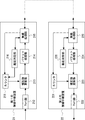
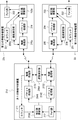
- FIG. 1 is a block diagram showing an overall configuration of a communication system 1000 according to the first embodiment of the present invention.
- the communication system 1000 includes a GNSS satellite 11, a GNSS receiver 12, a master device 13, a slave device 14, a first wireless relay device 21, and a second wireless relay device 22.
- the communication system 1000 according to the first embodiment only needs to include at least the master device 13, the slave device 14, the first wireless relay device 21, and the second wireless relay device 22.
- the GNSS receiver 12 is a receiver in the satellite navigation system, and receives a navigation signal from the GNSS satellite 11 or the like. Note that the GNSS satellite 11 and the GNSS receiver 12 are known ones, and thus detailed description thereof is omitted.
- the wired transmission lines 31 and 32 are, for example, transmission lines based on Ethernet (registered trademark).
- the time synchronization packet includes a correction value for performing time synchronization.
- the correction value is the sum of the time in which the time synchronization packet stays in each relay device that relays the time synchronization packet between the master device 13 and the slave device 14.
- the correction value is a value set in the overhead correction field in the PTP packet.
- the first wireless relay device 21 measures Round Trip Delay (RTD) with the second wireless relay device 22.
- RTD Round Trip Delay
- the first radio relay apparatus 21 transmits the first radio frame in which the delay measurement pulse (first pulse) is set to the second radio relay apparatus 22.
- the second wireless relay device 22 returns the second wireless frame in which the delay measurement pulse (second pulse) is set to the first wireless relay device 21.
- either one of the first radio relay device 21 and the second radio relay device 22 has the first radio calculated based on at least the setting of the first pulse and the detection of the second pulse.
- the correction value included in the time synchronization packet is adjusted using the transmission delay time between the relay device 21 and the second wireless relay device 33.
- the delay measurement pulse which is the first pulse and the second pulse described above is information that can be given periodicity like the frame pulse described above.
- the delay measurement pulse only needs to be set at least once for each of the first radio frame and the second radio frame that is returned. Therefore, the delay measurement pulse can use information such as a signal or data that can be detected by each of the first wireless relay device 21 and the second wireless relay device 22.
- the delay measurement pulse can be expressed by a signal of at least 1 bit. Therefore, the first pulse and the second pulse are simply expressed as the first signal and the second signal, the first data and the second data, or the first information and the second information. Also good.
- the second radio relay device 22 sets a delay measurement pulse (second pulse) to the second radio frame, and sets the second radio frame to the first radio frame. It transmits to the radio relay apparatus 21 (S12). That is, when the second radio relay device 22 receives the first radio frame in which the first pulse is set from the first radio relay device 21, the second radio relay device 22 in which the second pulse is set. Wrap the frame and reply.
- second pulse delay measurement pulse
- the second radio relay apparatus 22 performs the second radio frame return processing time dt (second time) for the first radio frame based on the detection of the first pulse and the setting of the second pulse. Is measured (S14).
- one relay device calculates a transmission delay time between the first wireless relay device 21 and the second wireless relay device 22 based on the RTD and the return processing time dt (S16).
- the following equation (1) may be mentioned.
- Transmission delay time (RTD ⁇ dt) / 2 (1)
- one relay device adjusts the correction value using the transmission delay time (S17).
- adjusting the correction value means performing correction related to the timing for clearing the count value of the counter included in one relay apparatus, or adding the transmission delay time to the correction value, and the like. Shall be included.
- Example 1 which is a specific example of Embodiment 1 of the present invention will be described.
- the first embodiment shows a case where the first wireless relay device 21 is “one relay device” and “adjusting the correction value” is correction related to the timing for clearing the count value.
- the case where the clear timing is delayed among the corrections related to the timing for clearing the count value will be described. Therefore, in the first embodiment, it is possible to synchronize the counter value between the wireless relay devices.
- the packet processing unit 214 performs packet processing on the time synchronization packet received from the correction value update unit 213.
- the packet processing is various processing for the payload and overhead of the time synchronization packet in the first wireless relay device 21. For example, rewrite processing or the like. For this reason, the packet processing varies depending on the set values of the payload and overhead of the time synchronization packet. Then, the packet processing unit 214 outputs the time synchronization packet after the packet processing to the wireless processing unit 215.
- FIG. 4 is a diagram for explaining the concept of the synchronization pulse and the delay measurement pulse included in the radio frame according to the first embodiment of the present invention.
- the radio frame group RF1 is a set of radio frames transmitted from the first radio relay device 21 toward the second radio relay device 22.
- the radio frame F1 belonging to the radio frame group RF1 includes an overhead F11 and a payload F12.
- the radio frame F1 corresponds to a first radio frame.
- the frame pulse P11 and the delay measurement pulse P12 are multiplexed.
- the delay measurement pulse P12 corresponds to the first pulse described above.
- the frame pulse P11 is multiplexed in each overhead of each radio frame other than the radio frame F1.
- the delay measurement unit 216 receives a notification from the wireless processing unit 215 that the delay measurement pulse (second pulse) has been detected, the delay measurement unit 216 acquires the count value at this time from the counter 211 and holds it. Then, the delay measuring unit 216 measures the difference between the time when the first pulse is set and the time when the second pulse is detected as the RTD.
- the radio processing unit 225 outputs a time synchronization packet extracted from the payload of the radio frame to the packet processing unit 224.
- the second wireless relay device 22 sets the second pulse in response to the detection of the first pulse (S304).
- the radio processing unit 225 sets the delay measurement pulse P22 in the overhead F21 of the radio frame F2 in accordance with an instruction from the delay measurement unit 226.
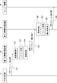
- FIG. 6 is a sequence diagram showing the flow of the correction field update process when relaying the time synchronization packet according to the first embodiment of the present invention. It is assumed that the processing of FIG. 5 is completed before the processing of FIG. 6 is started, and the count values of the counter 211 and the counter 221 are synchronized.
- the time synchronization packet is described as being a PTP packet.
- the master device 13 transmits a PTP packet addressed to the slave device 14 to the first wireless relay device 21 via the wired transmission path 31 (S21). At this time, the correction value is included in the PTP packet as described above.
Landscapes
- Engineering & Computer Science (AREA)
- Computer Networks & Wireless Communication (AREA)
- Signal Processing (AREA)
- Synchronisation In Digital Transmission Systems (AREA)
- Mobile Radio Communication Systems (AREA)
Abstract
Description
時刻同期を行うための補正値を含む時刻同期パケットを、当該時刻同期を行うマスタ装置から受信し、無線通信により転送する第1の無線中継装置と、
前記第1の無線中継装置から前記無線通信により受信した前記時刻同期パケットを、前記時刻同期を行うスレーブ装置へ転送する第2の無線中継装置と、
を備え、
前記第1の無線中継装置は、
第1のパルスを設定した第1の無線フレームを前記第2の無線中継装置へ送信し、
前記第2の無線中継装置は、
受信した前記第1の無線フレームから前記第1のパルスを検出し、
前記第1のパルスの検出に応じて、第2のパルスを設定した第2の無線フレームを前記第1の無線中継装置へ送信し、
前記第1の無線中継装置は、
受信した前記第2の無線フレームから前記第2のパルスを検出し、
前記第1の無線中継装置又は前記第2の無線中継装置のいずれか一方の中継装置は、
少なくとも前記第1のパルスの設定及び前記第2のパルスの検出に基づいて算出される前記第1の無線中継装置と前記第2の無線中継装置との間の伝送遅延時間を用いて、前記時刻同期パケットに含まれる前記補正値を調整する。
時刻同期を行うための補正値を含む時刻同期パケットを、当該時刻同期を行うマスタ装置から受信し、無線通信により転送する第1の無線中継装置と、
前記第1の無線中継装置から前記無線通信により受信した前記時刻同期パケットを、前記時刻同期を行うスレーブ装置へ転送する第2の無線中継装置と、
を備える通信システムにおける時刻同期方法であって、
前記第1の無線中継装置が、
第1のパルスを設定した第1の無線フレームを前記第2の無線中継装置へ送信し、
前記第2の無線中継装置が、
受信した前記第1の無線フレームから前記第1のパルスを検出し、
前記第1のパルスの検出に応じて、第2のパルスを設定した第2の無線フレームを前記第1の無線中継装置へ送信し、
前記第1の無線中継装置が、
受信した前記第2の無線フレームから前記第2のパルスを検出し、
前記第1の無線中継装置又は前記第2の無線中継装置のいずれか一方の中継装置が、
少なくとも前記第1のパルスの設定及び前記第2のパルスの検出に基づいて算出される前記第1の無線中継装置と前記第2の無線中継装置との間の伝送遅延時間を用いて、前記時刻同期パケットに含まれる前記補正値を調整する。
時刻同期を行うための補正値を含む時刻同期パケットを、当該時刻同期を行うマスタ装置とスレーブ装置との間で無線通信により中継する複数の無線中継装置のうちの一つであり、
第1の無線フレームに第1のパルスを設定し、当該第1の無線フレームを前記複数の無線中継装置のうちの他の無線中継装置へ送信し、当該他の無線中継装置から当該第1の無線フレームに対して折り返され、かつ、第2のパルスが設定された第2の無線フレームを受信し、当該第2の無線フレームから前記第2のパルスを検出する無線通信部と、
前記第1のパルスの設定及び前記第2のパルスの検出に基づいて自己と前記他の無線中継装置との間の伝送遅延時間を測定する測定部と、
前記伝送遅延時間を用いて当該時刻同期パケットに含まれる前記補正値を調整する調整部と、
を備える。
図1は、本発明の実施の形態1にかかる通信システム1000の全体構成を示すブロック図である。通信システム1000は、GNSS衛星11と、GNSS受信機12と、マスタ装置13と、スレーブ装置14と、第1の無線中継装置21と、第2の無線中継装置22とを備える。尚、本実施の形態1にかかる通信システム1000は、少なくともマスタ装置13と、スレーブ装置14と、第1の無線中継装置21と、第2の無線中継装置22とを備えるものであればよい。
伝送遅延時間 = (RTD - dt) / 2 ・・・(1)式
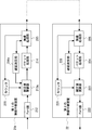
続いて、本発明の実施の形態1の具体例である実施例1について説明する。実施例1は、第1の無線中継装置21が「一方の中継装置」であり、「補正値を調整する」ことがカウント値をクリアするタイミングに関する補正である場合について示す。特に、カウント値をクリアするタイミングに関する補正のうち、クリアタイミングを遅らせる場合について示す。そのため、本実施例1では、無線中継装置間のカウンタ値の同期を行うことができる。
遅延測定部216は、第1の無線中継装置21と第2の無線中継装置22との間の伝送遅延時間を算出する場合に、遅延測定パルス(第1のパルス)の設定を無線処理部215へ指示する。そして、遅延測定部216は、遅延測定パルスの設定を指示した時点のカウント値をカウンタ211から取得し、保持する。
続いて、本発明の実施の形態1の具体例である実施例2について説明する。実施例2は、実施例1との違いとして、カウント値をクリアするタイミングに関する補正として、カウント値を補正する場合について示す。
Tmax - ((RTD - dt) / 2) ・・・(2)式
<実施例3>
続いて、本発明の実施の形態1の具体例である実施例3について説明する。実施例3は、実施例1との違いとして、「補正値を調整する」ことが伝送遅延時間を補正値から加算する場合について示す。
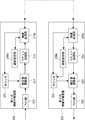
続いて、本発明の実施の形態1の具体例である実施例4について説明する。実施例4は、第2の無線中継装置22が「一方の中継装置」であり、「補正値を調整する」ことがカウント値をクリアするタイミングに関する補正である場合について示す。特に、クリアするタイミングに関する補正として、カウント値を補正する場合について示す。
続いて、本発明の実施の形態1の具体例である実施例5について説明する。実施例5は、実施例4との違いとして、「補正値を調整する」ことを、伝送遅延時間を補正値から加算することとする場合について示す。
本発明の実施形態2は、第1の無線中継装置に対向する中継装置が2台ある場合を示す。但し、本発明の実施形態2は第1の無線中継装置に対向する中継装置が3台以上であっても適用可能である。
前記第1の無線中継装置から前記無線通信により受信した前記時刻同期パケットを、前記時刻同期を行う他のスレーブ装置へ転送する第3の無線中継装置をさらに備え、
前記第1の無線中継装置は、
前記第1の無線フレームを前記第3の無線中継装置へさらに送信し、
前記第3の無線中継装置は、
受信した前記第1の無線フレームから前記第1のパルスを検出し、
前記第1のパルスの検出に応じて、第3のパルスを設定した第3の無線フレームを前記第1の無線中継装置へ送信し、
前記第1のパルスの検出時から前記第3のパルスの設定時までの第3の時間を測定し、
前記第1の無線中継装置は、
受信した前記第3の無線フレームから前記第3のパルスを検出し、
前記第1のパルスの設定時から前記第3のパルスの検出時までの第4の時間を測定し、
前記測定した前記第4の時間を前記第3の無線中継装置へ送信し、
前記第3の無線中継装置は、
前記第1の無線中継装置から受信した前記第4の時間と、自己が測定した前記第3の時間とを用いて、前記伝送遅延時間を算出し、
前記算出した前記伝送遅延時間を用いて前記補正値を調整する。
尚、本発明の実施形態1及び2と上述した特許文献1との違いについて補足する。まず、IEEE1588v2では超高精度の時刻同期(nsオーダの精度)を要求される。ここで、上述した特許文献1にかかる技術は、スレーブ装置で発生する「中継時間」を計測応答フレームに多重し、その値を用いて時刻同期を行い、中継時間は各スレーブ装置にて測定するものといえる。しかし、マスタ装置と各スレーブ装置は、通常、異なるクロックで動作している為、各スレーブ装置におけるクロック間隔(カウント間隔)には揺らぎがある。そのため、各スレーブ装置のカウンタで「中継時間」として測定した時間は、マスタ装置のカウンタを基準とした場合、カウント間隔の揺らぎによる誤差が発生する。例えば、マスタ装置とスレーブ装置の各カウンタに使用するクロック間隔にそれぞれ100ppmのズレがあったとする。このとき、スレーブ1台あたり100us転送時間かかる場合、100nsの誤差が生じる。スレーブ装置の3台で最大300ns、往復で最大600nsの誤差が発生し、高精度同期システムとしては精度が不十分と言わざるを得ない。
時刻同期を行うための補正値を含む時刻同期パケットを、当該時刻同期を行うマスタ装置とスレーブ装置との間で無線通信により中継する複数の無線中継装置のうちの一つであり、
第1の無線フレームに第1のパルスを設定し、当該第1の無線フレームを前記複数の無線中継装置のうちの他の無線中継装置へ送信し、当該他の無線中継装置から当該第1の無線フレームに対して折り返され、かつ、第2のパルスが設定された第2の無線フレームを受信し、当該第2の無線フレームから前記第2のパルスを検出する無線通信部と、
前記第1のパルスの設定及び前記第2のパルスの検出に基づいて自己と前記他の無線中継装置との間の伝送遅延時間を測定する測定部と、
前記伝送遅延時間を用いて当該時刻同期パケットに含まれる前記補正値を調整する調整部と、
を備える無線中継装置。
(付記1)
時刻同期を行うための補正値を含む時刻同期パケットを、当該時刻同期を行うマスタ装置から受信し、無線通信により転送する第1の無線中継装置と、
前記第1の無線中継装置から前記無線通信により受信した前記時刻同期パケットを、前記時刻同期を行うスレーブ装置へ転送する第2の無線中継装置と、
を備え、
前記第1の無線中継装置は、
第1のパルスを設定した第1の無線フレームを前記第2の無線中継装置へ送信し、
前記第2の無線中継装置は、
受信した前記第1の無線フレームから前記第1のパルスを検出し、
前記第1のパルスの検出に応じて、第2のパルスを設定した第2の無線フレームを前記第1の無線中継装置へ送信し、
前記第1の無線中継装置は、
受信した前記第2の無線フレームから前記第2のパルスを検出し、
前記第1の無線中継装置又は前記第2の無線中継装置のいずれか一方の中継装置は、
少なくとも前記第1のパルスの設定及び前記第2のパルスの検出に基づいて算出される前記第1の無線中継装置と前記第2の無線中継装置との間の伝送遅延時間を用いて、前記時刻同期パケットに含まれる前記補正値を調整する
通信システム。
(付記2)
前記第1の無線中継装置は、
前記第1のパルスの設定時から前記第2のパルスの検出時までの第1の時間を測定し、
前記第2の無線中継装置は、
前記第1のパルスの検出時から前記第2のパルスの設定時までの第2の時間を測定し、
前記第1の無線中継装置及び前記第2の無線中継装置は、
前記一方の中継装置に前記第1の時間及び前記第2の時間を集約させ、
前記一方の中継装置は、
前記第1の時間及び前記第2の時間に基づいて、前記伝送遅延時間を算出し、
前記算出した前記伝送遅延時間を用いて前記補正値を調整する
付記1に記載の通信システム。
(付記3)
前記一方の中継装置は、前記第1の無線中継装置であり、
前記第2の無線中継装置は、前記測定した前記第2の時間を前記第1の無線中継装置へ送信し、
前記第1の無線中継装置は、
前記第2の無線中継装置から受信した前記第2の時間と、自己が測定した前記第1の時間とを用いて、前記伝送遅延時間を算出し、
前記算出した前記伝送遅延時間を用いて前記補正値を調整する
付記2に記載の通信システム。
(付記4)
前記一方の中継装置は、前記第2の無線中継装置であり、
前記第1の無線中継装置は、前記測定した前記第1の時間を前記第2の無線中継装置へ送信し、
前記第2の無線中継装置は、
前記第1の無線中継装置から受信した前記第1の時間と、自己が測定した前記第2の時間とを用いて、前記伝送遅延時間を算出し、
前記算出した前記伝送遅延時間を用いて前記補正値を調整する
付記2に記載の通信システム。
(付記5)
前記第1の無線中継装置が有する第1のカウンタと前記第2の無線中継装置が有する第2のカウンタとは、前記第1の無線中継装置と前記第2の無線中継装置との間で送受信される任意の無線フレームに含まれる同期パルスの検出タイミングによりカウント間隔が同期しており、
前記一方の中継装置は、
前記伝送遅延時間に基づいて、前記第1及び前記第2のカウンタのうち当該一方の中継装置が有する対象カウンタのカウント値をクリアするタイミングに関する補正を行うことにより、前記補正値を調整する
付記1乃至4のいずれか1項に記載の通信システム。
(付記6)
前記一方の中継装置は、
前記対象カウンタのカウント値をクリアするタイミングを前記伝送遅延時間分変更することにより、前記タイミングに関する補正を行う
付記5に記載の通信システム。
(付記7)
前記一方の中継装置は、
前記対象カウンタのカウント値をクリアするタイミングにおいて、前記伝送遅延時間を用いて当該カウント値を修正することにより、前記タイミングに関する補正を行う
付記5に記載の通信システム。
(付記8)
前記一方の中継装置は、
前記伝送遅延時間を前記補正値に加算することにより、前記補正値を調整する
付記1乃至4のいずれか1項に記載の通信システム。
(付記9)
前記第1の無線中継装置から前記無線通信により受信した前記時刻同期パケットを、前記時刻同期を行う他のスレーブ装置へ転送する第3の無線中継装置をさらに備え、
前記第1の無線中継装置は、
前記第1の無線フレームを前記第3の無線中継装置へさらに送信し、
前記第3の無線中継装置は、
受信した前記第1の無線フレームから前記第1のパルスを検出し、
前記第1のパルスの検出に応じて、第3のパルスを設定した第3の無線フレームを前記第1の無線中継装置へ送信し、
前記第1のパルスの検出時から前記第3のパルスの設定時までの第3の時間を測定し、
前記第1の無線中継装置は、
受信した前記第3の無線フレームから前記第3のパルスを検出し、
前記第1のパルスの設定時から前記第3のパルスの検出時までの第4の時間を測定し、
前記測定した前記第4の時間を前記第3の無線中継装置へ送信し、
前記第3の無線中継装置は、
前記第1の無線中継装置から受信した前記第4の時間と、自己が測定した前記第3の時間とを用いて、前記伝送遅延時間を算出し、
前記算出した前記伝送遅延時間を用いて前記補正値を調整する
付記3に記載の通信システム。
(付記10)
前記補正値は、前記マスタ装置と前記スレーブ装置の間で前記時刻同期パケットの中継を行う各中継装置に当該時刻同期パケットが滞留した時間の総和である
付記1乃至8のいずれか1項に記載の通信システム。
(付記11)
時刻同期を行うための補正値を含む時刻同期パケットを、当該時刻同期を行うマスタ装置から受信し、無線通信により転送する第1の無線中継装置と、
前記第1の無線中継装置から前記無線通信により受信した前記時刻同期パケットを、前記時刻同期を行うスレーブ装置へ転送する第2の無線中継装置と、
を備える通信システムにおける時刻同期方法であって、
前記第1の無線中継装置が、
第1のパルスを設定した第1の無線フレームを前記第2の無線中継装置へ送信し、
前記第2の無線中継装置が、
受信した前記第1の無線フレームから前記第1のパルスを検出し、
前記第1のパルスの検出に応じて、第2のパルスを設定した第2の無線フレームを前記第1の無線中継装置へ送信し、
前記第1の無線中継装置が、
受信した前記第2の無線フレームから前記第2のパルスを検出し、
前記第1の無線中継装置又は前記第2の無線中継装置のいずれか一方の中継装置が、
少なくとも前記第1のパルスの設定及び前記第2のパルスの検出に基づいて算出される前記第1の無線中継装置と前記第2の無線中継装置との間の伝送遅延時間を用いて、前記時刻同期パケットに含まれる前記補正値を調整する
時刻同期方法。
(付記12)
時刻同期を行うための補正値を含む時刻同期パケットを、当該時刻同期を行うマスタ装置とスレーブ装置との間で無線通信により中継する複数の無線中継装置のうちの一つであり、
第1の無線フレームに第1のパルスを設定し、当該第1の無線フレームを前記複数の無線中継装置のうちの他の無線中継装置へ送信し、当該他の無線中継装置から当該第1の無線フレームに対して折り返され、かつ、第2のパルスが設定された第2の無線フレームを受信し、当該第2の無線フレームから前記第2のパルスを検出する無線通信部と、
前記第1のパルスの設定及び前記第2のパルスの検出に基づいて自己と前記他の無線中継装置との間の伝送遅延時間を測定する測定部と、
前記伝送遅延時間を用いて当該時刻同期パケットに含まれる前記補正値を調整する調整部と、
を備える無線中継装置。
11 GNSS衛星
12 GNSS受信機
13 マスタ装置
14 スレーブ装置
21 第1の無線中継装置
21a 第1の無線中継装置
21b 第1の無線中継装置
21c 第1の無線中継装置
21d 第1の無線中継装置
211 カウンタ
212 Port部
213 補正値更新部
213a 補正値更新部
213d 補正値更新部
214 パケット処理部
2141 パケット処理部
2142 パケット処理部
215 無線処理部
2151 無線処理部
2152 無線処理部
215c 無線処理部
216 遅延測定部
216b 遅延測定部
216c 遅延測定部
216d 遅延測定部
22 第2の無線中継装置
22b 第2の無線中継装置
22c 第2の無線中継装置
221 カウンタ
222 Port部
223 補正値更新部
223c 補正値更新部
224 パケット処理部
225 無線処理部
225b 無線処理部
225c 無線処理部
226 遅延測定部
226b 遅延測定部
226c 遅延測定部
23 第3の無線中継装置
231 カウンタ
232 Port部
233 補正値更新部
234 パケット処理部
235 無線処理部
236 遅延測定部
31 有線伝送路
32 有線伝送路
33 無線伝送路
RF1 無線フレーム群
F1 無線フレーム
F11 オーバーヘッド
F12 ペイロード
F13 オーバーヘッド
F14 ペイロード
P11 フレームパルス
P12 遅延測定パルス
PTP 時刻同期パケット
CF 補正値
RF2 無線フレーム群
F2 無線フレーム
F21 オーバーヘッド
F22 ペイロード
P21 フレームパルス
P22 遅延測定パルス
Claims (12)
- 時刻同期を行うための補正値を含む時刻同期パケットを、当該時刻同期を行うマスタ装置から受信し、無線通信により転送する第1の無線中継装置と、
前記第1の無線中継装置から前記無線通信により受信した前記時刻同期パケットを、前記時刻同期を行うスレーブ装置へ転送する第2の無線中継装置と、
を備え、
前記第1の無線中継装置は、
第1のパルスを設定した第1の無線フレームを前記第2の無線中継装置へ送信し、
前記第2の無線中継装置は、
受信した前記第1の無線フレームから前記第1のパルスを検出し、
前記第1のパルスの検出に応じて、第2のパルスを設定した第2の無線フレームを前記第1の無線中継装置へ送信し、
前記第1の無線中継装置は、
受信した前記第2の無線フレームから前記第2のパルスを検出し、
前記第1の無線中継装置又は前記第2の無線中継装置のいずれか一方の中継装置は、
少なくとも前記第1のパルスの設定及び前記第2のパルスの検出に基づいて算出される前記第1の無線中継装置と前記第2の無線中継装置との間の伝送遅延時間を用いて、前記時刻同期パケットに含まれる前記補正値を調整する
通信システム。 - 前記第1の無線中継装置は、
前記第1のパルスの設定時から前記第2のパルスの検出時までの第1の時間を測定し、
前記第2の無線中継装置は、
前記第1のパルスの検出時から前記第2のパルスの設定時までの第2の時間を測定し、
前記第1の無線中継装置及び前記第2の無線中継装置は、
前記一方の中継装置に前記第1の時間及び前記第2の時間を集約させ、
前記一方の中継装置は、
前記第1の時間及び前記第2の時間に基づいて、前記伝送遅延時間を算出し、
前記算出した前記伝送遅延時間を用いて前記補正値を調整する
請求項1に記載の通信システム。 - 前記一方の中継装置は、前記第1の無線中継装置であり、
前記第2の無線中継装置は、前記測定した前記第2の時間を前記第1の無線中継装置へ送信し、
前記第1の無線中継装置は、
前記第2の無線中継装置から受信した前記第2の時間と、自己が測定した前記第1の時間とを用いて、前記伝送遅延時間を算出し、
前記算出した前記伝送遅延時間を用いて前記補正値を調整する
請求項2に記載の通信システム。 - 前記一方の中継装置は、前記第2の無線中継装置であり、
前記第1の無線中継装置は、前記測定した前記第1の時間を前記第2の無線中継装置へ送信し、
前記第2の無線中継装置は、
前記第1の無線中継装置から受信した前記第1の時間と、自己が測定した前記第2の時間とを用いて、前記伝送遅延時間を算出し、
前記算出した前記伝送遅延時間を用いて前記補正値を調整する
請求項2に記載の通信システム。 - 前記第1の無線中継装置が有する第1のカウンタと前記第2の無線中継装置が有する第2のカウンタとは、前記第1の無線中継装置と前記第2の無線中継装置との間で送受信される任意の無線フレームに含まれる同期パルスの検出タイミングによりカウント間隔が同期しており、
前記一方の中継装置は、
前記伝送遅延時間に基づいて、前記第1及び前記第2のカウンタのうち当該一方の中継装置が有する対象カウンタのカウント値をクリアするタイミングに関する補正を行うことにより、前記補正値を調整する
請求項1乃至4のいずれか1項に記載の通信システム。 - 前記一方の中継装置は、
前記対象カウンタのカウント値をクリアするタイミングを前記伝送遅延時間分変更することにより、前記タイミングに関する補正を行う
請求項5に記載の通信システム。 - 前記一方の中継装置は、
前記対象カウンタのカウント値をクリアするタイミングにおいて、前記伝送遅延時間を用いて当該カウント値を修正することにより、前記タイミングに関する補正を行う
請求項5に記載の通信システム。 - 前記一方の中継装置は、
前記伝送遅延時間を前記補正値に加算することにより、前記補正値を調整する
請求項1乃至4のいずれか1項に記載の通信システム。 - 前記第1の無線中継装置から前記無線通信により受信した前記時刻同期パケットを、前記時刻同期を行う他のスレーブ装置へ転送する第3の無線中継装置をさらに備え、
前記第1の無線中継装置は、
前記第1の無線フレームを前記第3の無線中継装置へさらに送信し、
前記第3の無線中継装置は、
受信した前記第1の無線フレームから前記第1のパルスを検出し、
前記第1のパルスの検出に応じて、第3のパルスを設定した第3の無線フレームを前記第1の無線中継装置へ送信し、
前記第1のパルスの検出時から前記第3のパルスの設定時までの第3の時間を測定し、
前記第1の無線中継装置は、
受信した前記第3の無線フレームから前記第3のパルスを検出し、
前記第1のパルスの設定時から前記第3のパルスの検出時までの第4の時間を測定し、
前記測定した前記第4の時間を前記第3の無線中継装置へ送信し、
前記第3の無線中継装置は、
前記第1の無線中継装置から受信した前記第4の時間と、自己が測定した前記第3の時間とを用いて、前記伝送遅延時間を算出し、
前記算出した前記伝送遅延時間を用いて前記補正値を調整する
請求項3に記載の通信システム。 - 前記補正値は、前記マスタ装置と前記スレーブ装置の間で前記時刻同期パケットの中継を行う各中継装置に当該時刻同期パケットが滞留した時間の総和である
請求項1乃至8のいずれか1項に記載の通信システム。 - 時刻同期を行うための補正値を含む時刻同期パケットを、当該時刻同期を行うマスタ装置から受信し、無線通信により転送する第1の無線中継装置と、
前記第1の無線中継装置から前記無線通信により受信した前記時刻同期パケットを、前記時刻同期を行うスレーブ装置へ転送する第2の無線中継装置と、
を備える通信システムにおける時刻同期方法であって、
前記第1の無線中継装置が、
第1のパルスを設定した第1の無線フレームを前記第2の無線中継装置へ送信し、
前記第2の無線中継装置が、
受信した前記第1の無線フレームから前記第1のパルスを検出し、
前記第1のパルスの検出に応じて、第2のパルスを設定した第2の無線フレームを前記第1の無線中継装置へ送信し、
前記第1の無線中継装置が、
受信した前記第2の無線フレームから前記第2のパルスを検出し、
前記第1の無線中継装置又は前記第2の無線中継装置のいずれか一方の中継装置が、
少なくとも前記第1のパルスの設定及び前記第2のパルスの検出に基づいて算出される前記第1の無線中継装置と前記第2の無線中継装置との間の伝送遅延時間を用いて、前記時刻同期パケットに含まれる前記補正値を調整する
時刻同期方法。 - 時刻同期を行うための補正値を含む時刻同期パケットを、当該時刻同期を行うマスタ装置とスレーブ装置との間で無線通信により中継する複数の無線中継装置のうちの一つであり、
第1の無線フレームに第1のパルスを設定し、当該第1の無線フレームを前記複数の無線中継装置のうちの他の無線中継装置へ送信し、当該他の無線中継装置から当該第1の無線フレームに対して折り返され、かつ、第2のパルスが設定された第2の無線フレームを受信し、当該第2の無線フレームから前記第2のパルスを検出する無線通信手段と、
前記第1のパルスの設定及び前記第2のパルスの検出に基づいて自己と前記他の無線中継装置との間の伝送遅延時間を測定する測定手段と、
前記伝送遅延時間を用いて当該時刻同期パケットに含まれる前記補正値を調整する調整手段と、
を備える無線中継装置。
Priority Applications (2)
| Application Number | Priority Date | Filing Date | Title |
|---|---|---|---|
| JP2016557441A JPWO2016072038A1 (ja) | 2014-11-05 | 2015-08-19 | 通信システム、時刻同期方法及び無線中継装置 |
| US15/524,410 US10333611B2 (en) | 2014-11-05 | 2015-08-19 | Communication system, time synchronization method, and radio relay device |
Applications Claiming Priority (2)
| Application Number | Priority Date | Filing Date | Title |
|---|---|---|---|
| JP2014-224840 | 2014-11-05 | ||
| JP2014224840 | 2014-11-05 |
Related Child Applications (1)
| Application Number | Title | Priority Date | Filing Date |
|---|---|---|---|
| US15/524,410 Continuation US10333611B2 (en) | 2014-11-05 | 2015-08-19 | Communication system, time synchronization method, and radio relay device |
Publications (1)
| Publication Number | Publication Date |
|---|---|
| WO2016072038A1 true WO2016072038A1 (ja) | 2016-05-12 |
Family
ID=55908787
Family Applications (1)
| Application Number | Title | Priority Date | Filing Date |
|---|---|---|---|
| PCT/JP2015/004126 Ceased WO2016072038A1 (ja) | 2014-11-05 | 2015-08-19 | 通信システム、時刻同期方法及び無線中継装置 |
Country Status (3)
| Country | Link |
|---|---|
| US (1) | US10333611B2 (ja) |
| JP (1) | JPWO2016072038A1 (ja) |
| WO (1) | WO2016072038A1 (ja) |
Cited By (5)
| Publication number | Priority date | Publication date | Assignee | Title |
|---|---|---|---|---|
| WO2018163678A1 (ja) * | 2017-03-10 | 2018-09-13 | 日本電気株式会社 | 通信システム |
| JP2019110417A (ja) * | 2017-12-18 | 2019-07-04 | 一般財団法人電力中央研究所 | 時刻同期方法、時刻同期プログラム、および時刻同期装置、並びに、時刻同期システム |
| WO2020152861A1 (ja) | 2019-01-25 | 2020-07-30 | 株式会社安川電機 | 産業機械システム、通信方法及び無線アクセスポイント |
| JP2021077974A (ja) * | 2019-11-07 | 2021-05-20 | 日本放送協会 | 無線伝送システム及び無線中継装置 |
| US11991654B2 (en) | 2020-11-16 | 2024-05-21 | Nec Corporation | Communication system, communication method, and communication program |
Families Citing this family (9)
| Publication number | Priority date | Publication date | Assignee | Title |
|---|---|---|---|---|
| JP6603437B2 (ja) * | 2017-03-27 | 2019-11-06 | 株式会社日立国際電気 | 放送波同期信号変換装置 |
| US10652847B2 (en) * | 2017-09-25 | 2020-05-12 | JVC Kenwood Corporation | Simulcast controller, relay station, and communication method operated on simulcasting |
| FR3076411B1 (fr) * | 2017-12-29 | 2020-10-30 | Avantix | Synchroniseur adaptatif pour une chaine de demodulation |
| JP6984482B2 (ja) * | 2018-02-22 | 2021-12-22 | オムロン株式会社 | 通信システム、通信装置および通信方法 |
| TWI713351B (zh) * | 2019-07-09 | 2020-12-11 | 啟碁科技股份有限公司 | 設定同步方法及網狀網路系統 |
| JP2021044629A (ja) * | 2019-09-06 | 2021-03-18 | 株式会社東芝 | ネットワークシステム、送信装置及び受信装置 |
| CN113472417B (zh) * | 2021-04-06 | 2023-02-03 | 中国科学院空天信息创新研究院 | 多星编队的雷达定时同步方法、装置、设备及存储介质 |
| KR20240161372A (ko) * | 2023-05-04 | 2024-11-12 | 삼성전자주식회사 | 블루투스 연결을 증폭하는 모바일 장치, 그것을 갖는 무선 통신 시스템, 및 그것의 동작 방법 |
| CN118102435B (zh) * | 2024-04-23 | 2024-07-30 | 杭州海联物联科技有限公司 | 远距离多设备脉冲通信方法及其通信设备 |
Citations (3)
| Publication number | Priority date | Publication date | Assignee | Title |
|---|---|---|---|---|
| JPH05161181A (ja) * | 1991-12-10 | 1993-06-25 | Nec Corp | 時刻同期方式 |
| JP2012034224A (ja) * | 2010-07-30 | 2012-02-16 | Hitachi Cable Ltd | 中継機器 |
| JP2014078781A (ja) * | 2012-10-09 | 2014-05-01 | Hitachi Ltd | 通信制御装置 |
Family Cites Families (3)
| Publication number | Priority date | Publication date | Assignee | Title |
|---|---|---|---|---|
| DE60127916T2 (de) * | 2000-10-06 | 2008-01-17 | Kabushiki Kaisha Toshiba | Digitales Schutzrelaissystem |
| US20150187209A1 (en) * | 2006-01-31 | 2015-07-02 | Sigma Designs, Inc. | Method and system for synchronization and remote control of controlling units |
| JP2012175567A (ja) | 2011-02-23 | 2012-09-10 | Mitsubishi Electric Corp | 同期システムおよび同期システムの同期方法 |
-
2015
- 2015-08-19 JP JP2016557441A patent/JPWO2016072038A1/ja active Pending
- 2015-08-19 US US15/524,410 patent/US10333611B2/en not_active Expired - Fee Related
- 2015-08-19 WO PCT/JP2015/004126 patent/WO2016072038A1/ja not_active Ceased
Patent Citations (3)
| Publication number | Priority date | Publication date | Assignee | Title |
|---|---|---|---|---|
| JPH05161181A (ja) * | 1991-12-10 | 1993-06-25 | Nec Corp | 時刻同期方式 |
| JP2012034224A (ja) * | 2010-07-30 | 2012-02-16 | Hitachi Cable Ltd | 中継機器 |
| JP2014078781A (ja) * | 2012-10-09 | 2014-05-01 | Hitachi Ltd | 通信制御装置 |
Cited By (6)
| Publication number | Priority date | Publication date | Assignee | Title |
|---|---|---|---|---|
| WO2018163678A1 (ja) * | 2017-03-10 | 2018-09-13 | 日本電気株式会社 | 通信システム |
| JP2019110417A (ja) * | 2017-12-18 | 2019-07-04 | 一般財団法人電力中央研究所 | 時刻同期方法、時刻同期プログラム、および時刻同期装置、並びに、時刻同期システム |
| JP7039125B2 (ja) | 2017-12-18 | 2022-03-22 | 一般財団法人電力中央研究所 | 時刻同期方法、時刻同期プログラム、および時刻同期装置、並びに、時刻同期システム |
| WO2020152861A1 (ja) | 2019-01-25 | 2020-07-30 | 株式会社安川電機 | 産業機械システム、通信方法及び無線アクセスポイント |
| JP2021077974A (ja) * | 2019-11-07 | 2021-05-20 | 日本放送協会 | 無線伝送システム及び無線中継装置 |
| US11991654B2 (en) | 2020-11-16 | 2024-05-21 | Nec Corporation | Communication system, communication method, and communication program |
Also Published As
| Publication number | Publication date |
|---|---|
| US20180287688A1 (en) | 2018-10-04 |
| US10333611B2 (en) | 2019-06-25 |
| JPWO2016072038A1 (ja) | 2017-08-10 |
Similar Documents
| Publication | Publication Date | Title |
|---|---|---|
| WO2016072038A1 (ja) | 通信システム、時刻同期方法及び無線中継装置 | |
| US20170064661A1 (en) | Base station system, radio device and method | |
| US9548831B2 (en) | Synchronizing system, synchronizing method, first synchronizing device, second synchronizing device, and computer program | |
| JP5515735B2 (ja) | 時刻同期システム、マスタノード、スレーブノード、中継装置、時刻同期方法及び時刻同期用プログラム | |
| JP5358813B2 (ja) | ネットワークノード、時刻同期方法及びネットワークシステム | |
| US8081663B2 (en) | Time synchronization method and relay apparatus | |
| US10341083B2 (en) | System and methods for network synchronization | |
| US8953645B2 (en) | Communication system, communication apparatus and time synchronization method | |
| US20130279525A1 (en) | Ring Based Precise Time Data Network Clock Phase Adjustments | |
| EP2805441A1 (en) | Data transmission over packet switched network | |
| US20150092794A1 (en) | Method and devices for compensating for path asymmetry | |
| US12204291B2 (en) | Time transmission correction device, time transmission system, and delay measurement method | |
| WO2014083725A1 (ja) | 同期装置、同期システム、無線通信装置及び同期方法 | |
| WO2015122175A1 (ja) | 時刻同期装置、時刻同期システム及び時刻同期方法 | |
| KR20160126325A (ko) | 광전달망 시스템에서의 데이터 손실을 최소화하는 보호절체 장치 및 방법 | |
| JP6879234B2 (ja) | 時刻同期装置及び時刻同期方法 | |
| JP2017216563A (ja) | 中継装置、制御方法、及び、通信システム | |
| JP6170456B2 (ja) | スレーブノード、制御サーバ、時刻同期先決定方法及びコンピュータプログラム | |
| CN106160909A (zh) | 闰秒跳变的处理方法及装置 | |
| JP2009260881A (ja) | 基地局間同期方法および該方法を用いた移動通信システム | |
| US9379833B2 (en) | Transmitter, transmission method, and non-transitory computer-readable medium storing program | |
| WO2020195573A1 (ja) | 時刻同期システム、中継装置、時刻同期方法、及び非一時的なコンピュータ可読媒体 | |
| JP5391964B2 (ja) | クロック同期方法及びパケット通信システム | |
| JP7070387B2 (ja) | 時刻比較装置、および、時刻品質監視方法 | |
| US11804920B2 (en) | Signal transfer management device, signal transfer management method and signal transfer management program |
Legal Events
| Date | Code | Title | Description |
|---|---|---|---|
| 121 | Ep: the epo has been informed by wipo that ep was designated in this application |
Ref document number: 15856337 Country of ref document: EP Kind code of ref document: A1 |
|
| ENP | Entry into the national phase |
Ref document number: 2016557441 Country of ref document: JP Kind code of ref document: A |
|
| WWE | Wipo information: entry into national phase |
Ref document number: 15524410 Country of ref document: US |
|
| NENP | Non-entry into the national phase |
Ref country code: DE |
|
| 122 | Ep: pct application non-entry in european phase |
Ref document number: 15856337 Country of ref document: EP Kind code of ref document: A1 |