WO2016067971A1 - 海中浮遊式海流発電装置 - Google Patents
海中浮遊式海流発電装置 Download PDFInfo
- Publication number
- WO2016067971A1 WO2016067971A1 PCT/JP2015/079566 JP2015079566W WO2016067971A1 WO 2016067971 A1 WO2016067971 A1 WO 2016067971A1 JP 2015079566 W JP2015079566 W JP 2015079566W WO 2016067971 A1 WO2016067971 A1 WO 2016067971A1
- Authority
- WO
- WIPO (PCT)
- Prior art keywords
- blade
- ocean current
- power generation
- current power
- phase
- Prior art date
- Legal status (The legal status is an assumption and is not a legal conclusion. Google has not performed a legal analysis and makes no representation as to the accuracy of the status listed.)
- Ceased
Links
Images





Classifications
-
- F—MECHANICAL ENGINEERING; LIGHTING; HEATING; WEAPONS; BLASTING
- F03—MACHINES OR ENGINES FOR LIQUIDS; WIND, SPRING, OR WEIGHT MOTORS; PRODUCING MECHANICAL POWER OR A REACTIVE PROPULSIVE THRUST, NOT OTHERWISE PROVIDED FOR
- F03B—MACHINES OR ENGINES FOR LIQUIDS
- F03B13/00—Adaptations of machines or engines for special use; Combinations of machines or engines with driving or driven apparatus; Power stations or aggregates
- F03B13/10—Submerged units incorporating electric generators or motors
-
- F—MECHANICAL ENGINEERING; LIGHTING; HEATING; WEAPONS; BLASTING
- F03—MACHINES OR ENGINES FOR LIQUIDS; WIND, SPRING, OR WEIGHT MOTORS; PRODUCING MECHANICAL POWER OR A REACTIVE PROPULSIVE THRUST, NOT OTHERWISE PROVIDED FOR
- F03B—MACHINES OR ENGINES FOR LIQUIDS
- F03B13/00—Adaptations of machines or engines for special use; Combinations of machines or engines with driving or driven apparatus; Power stations or aggregates
- F03B13/12—Adaptations of machines or engines for special use; Combinations of machines or engines with driving or driven apparatus; Power stations or aggregates characterised by using wave or tide energy
- F03B13/26—Adaptations of machines or engines for special use; Combinations of machines or engines with driving or driven apparatus; Power stations or aggregates characterised by using wave or tide energy using tide energy
-
- F—MECHANICAL ENGINEERING; LIGHTING; HEATING; WEAPONS; BLASTING
- F03—MACHINES OR ENGINES FOR LIQUIDS; WIND, SPRING, OR WEIGHT MOTORS; PRODUCING MECHANICAL POWER OR A REACTIVE PROPULSIVE THRUST, NOT OTHERWISE PROVIDED FOR
- F03B—MACHINES OR ENGINES FOR LIQUIDS
- F03B15/00—Controlling
-
- F—MECHANICAL ENGINEERING; LIGHTING; HEATING; WEAPONS; BLASTING
- F03—MACHINES OR ENGINES FOR LIQUIDS; WIND, SPRING, OR WEIGHT MOTORS; PRODUCING MECHANICAL POWER OR A REACTIVE PROPULSIVE THRUST, NOT OTHERWISE PROVIDED FOR
- F03B—MACHINES OR ENGINES FOR LIQUIDS
- F03B17/00—Other machines or engines
- F03B17/06—Other machines or engines using liquid flow with predominantly kinetic energy conversion, e.g. of swinging-flap type, "run-of-river", "ultra-low head"
- F03B17/061—Other machines or engines using liquid flow with predominantly kinetic energy conversion, e.g. of swinging-flap type, "run-of-river", "ultra-low head" with rotation axis substantially in flow direction
-
- F—MECHANICAL ENGINEERING; LIGHTING; HEATING; WEAPONS; BLASTING
- F05—INDEXING SCHEMES RELATING TO ENGINES OR PUMPS IN VARIOUS SUBCLASSES OF CLASSES F01-F04
- F05B—INDEXING SCHEME RELATING TO WIND, SPRING, WEIGHT, INERTIA OR LIKE MOTORS, TO MACHINES OR ENGINES FOR LIQUIDS COVERED BY SUBCLASSES F03B, F03D AND F03G
- F05B2220/00—Application
- F05B2220/70—Application in combination with
- F05B2220/706—Application in combination with an electrical generator
-
- F—MECHANICAL ENGINEERING; LIGHTING; HEATING; WEAPONS; BLASTING
- F05—INDEXING SCHEMES RELATING TO ENGINES OR PUMPS IN VARIOUS SUBCLASSES OF CLASSES F01-F04
- F05B—INDEXING SCHEME RELATING TO WIND, SPRING, WEIGHT, INERTIA OR LIKE MOTORS, TO MACHINES OR ENGINES FOR LIQUIDS COVERED BY SUBCLASSES F03B, F03D AND F03G
- F05B2240/00—Components
- F05B2240/90—Mounting on supporting structures or systems
- F05B2240/97—Mounting on supporting structures or systems on a submerged structure
-
- F—MECHANICAL ENGINEERING; LIGHTING; HEATING; WEAPONS; BLASTING
- F05—INDEXING SCHEMES RELATING TO ENGINES OR PUMPS IN VARIOUS SUBCLASSES OF CLASSES F01-F04
- F05B—INDEXING SCHEME RELATING TO WIND, SPRING, WEIGHT, INERTIA OR LIKE MOTORS, TO MACHINES OR ENGINES FOR LIQUIDS COVERED BY SUBCLASSES F03B, F03D AND F03G
- F05B2270/00—Control
- F05B2270/10—Purpose of the control system
- F05B2270/101—Purpose of the control system to control rotational speed (n)
-
- F—MECHANICAL ENGINEERING; LIGHTING; HEATING; WEAPONS; BLASTING
- F05—INDEXING SCHEMES RELATING TO ENGINES OR PUMPS IN VARIOUS SUBCLASSES OF CLASSES F01-F04
- F05B—INDEXING SCHEME RELATING TO WIND, SPRING, WEIGHT, INERTIA OR LIKE MOTORS, TO MACHINES OR ENGINES FOR LIQUIDS COVERED BY SUBCLASSES F03B, F03D AND F03G
- F05B2270/00—Control
- F05B2270/10—Purpose of the control system
- F05B2270/20—Purpose of the control system to optimise the performance of a machine
-
- Y—GENERAL TAGGING OF NEW TECHNOLOGICAL DEVELOPMENTS; GENERAL TAGGING OF CROSS-SECTIONAL TECHNOLOGIES SPANNING OVER SEVERAL SECTIONS OF THE IPC; TECHNICAL SUBJECTS COVERED BY FORMER USPC CROSS-REFERENCE ART COLLECTIONS [XRACs] AND DIGESTS
- Y02—TECHNOLOGIES OR APPLICATIONS FOR MITIGATION OR ADAPTATION AGAINST CLIMATE CHANGE
- Y02E—REDUCTION OF GREENHOUSE GAS [GHG] EMISSIONS, RELATED TO ENERGY GENERATION, TRANSMISSION OR DISTRIBUTION
- Y02E10/00—Energy generation through renewable energy sources
- Y02E10/20—Hydro energy
-
- Y—GENERAL TAGGING OF NEW TECHNOLOGICAL DEVELOPMENTS; GENERAL TAGGING OF CROSS-SECTIONAL TECHNOLOGIES SPANNING OVER SEVERAL SECTIONS OF THE IPC; TECHNICAL SUBJECTS COVERED BY FORMER USPC CROSS-REFERENCE ART COLLECTIONS [XRACs] AND DIGESTS
- Y02—TECHNOLOGIES OR APPLICATIONS FOR MITIGATION OR ADAPTATION AGAINST CLIMATE CHANGE
- Y02E—REDUCTION OF GREENHOUSE GAS [GHG] EMISSIONS, RELATED TO ENERGY GENERATION, TRANSMISSION OR DISTRIBUTION
- Y02E10/00—Energy generation through renewable energy sources
- Y02E10/30—Energy from the sea, e.g. using wave energy or salinity gradient
Definitions
- the present invention relates to an ocean current power generation device that generates electricity using ocean current energy, and more particularly to an underwater floating ocean current power generation device that uses a power generation device suspended in the sea.
- an underwater floating ocean current power generation device (underwater floating ocean current power generation device), which is disclosed in Patent Document 1, for example.
- This submerged floating current generator is connected to a mooring line extending from the seabed by connecting the current generator configured as a floating body with a certain buoyancy, so that the ocean current generator floats in the sea within the range allowed by the mooring line. In this way, power is generated.
- a submerged floating ocean current power generation apparatus does not require a huge support like a wind power generation apparatus installed on the ground, and can have a simple configuration.
- FIG. 14 is a perspective view showing the underwater floating ocean current power generation apparatus disclosed in Patent Document 1.
- this submerged floating current generator is configured as a floating body 1, and in order to stabilize the posture of the floating body 1, two ocean current generator main bodies 2 and 2 are connected to each other.
- the twin-bore type that forms one floating body 1 from 3 is adopted.
- the ocean current power generator main body 2 is equipped with a generator (not shown) in a nacelle (also referred to as a pod) 4, and the rotating shaft of the rotor blade 5 is connected to the rotor of this generator.
- the nacelle 4 is coupled to the left and right ends of the structure 3.
- the tip of the mooring line 6 is coupled to the center of the structure 3 in the left-right direction, and the base end of the mooring line 6 is locked to the seabed.
- the floating body 1 floats in the sea in the horizontal direction and the vertical direction within a range restrained by the mooring line 6.
- the buoyancy of the floating body 1 is balanced on the left and right, and the structure 3 of the floating body 1 is formed in a wing shape that opposes the ocean current direction.
- the floating body 1 implements power generation by changing the direction according to the ocean current so that the front surface (the front surface of the rotary blade 5) faces the ocean current direction.
- this ocean current power generation apparatus employs a downwind system in which the rotor blades 5 are arranged behind the nacelle 4 (downstream of the ocean current).
- the rotary blade 5 By arranging the rotary blade 5 on the downstream side of the nacelle 4 in this way, the front surface of the floating body 1 (the front surface of the rotary blade 5) can be easily directed in the ocean current direction.
- the nacelle 4 and the structure 3 are formed so as to be directed in the direction of the ocean current, and the front direction of the floating body 1 is set so as to passively face the ocean current direction.
- the floating body (sea current power generation device) 1 locked to the mooring line 6 floats in the sea.
- the floating body 1 has the acting force of the ocean current applied to the floating body 1, the buoyancy generated in the floating body 1, and the mooring line. 6 takes a balanced position with the tension. That is, the buoyancy acts vertically upward on the floating body 1, the acting force of the ocean current acts in the direction of the ocean current (horizontal direction), and the tension of the mooring line acts so as to oppose the buoyancy and the acting force of the ocean current. .
- the floating body 1 rises to a relatively shallow depth in the sea, and if the acting force of the ocean current is strong (that is, if the velocity of the ocean current is high). The floating body 1 descends to a relatively deep depth in the sea.
- the flow velocity distribution in the depth direction of the ocean current becomes lower as it gets closer to the sea floor near the sea floor and becomes higher as it gets farther from the sea floor. For this reason, if the flow velocity of the ocean current increases, the floating body 1 descends in the sea and balances at a depth at which the flow velocity is appropriately weakened by the flow velocity distribution in the depth direction. Moreover, if the flow velocity of an ocean current becomes weak, the floating body 1 rises in the sea and balances at a depth at which the flow velocity is appropriately strengthened by a flow velocity distribution in the depth direction.
- two ocean current generator bodies 2 and 2 are connected by a structure 3 as shown in FIG. It is preferable to adopt a twin-bottle type in which two floating bodies 1 are configured.
- the rotary blade 5 is arranged behind the nacelle 4 (downstream of the ocean current) so that the front surface of the floating body 1 (the front surface of the rotor blade 5) faces the ocean current direction without requiring a special device. It is preferable to adopt a window system.
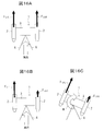
- the twin body type is adopted for the floating body 1, it is of course configured to be bilaterally symmetric, and the acting force (thrust force) of the ocean current applied to the left and right rotor blades 5 is always equal as shown by the white arrows in FIG. 16A. It is preferable to do so.
- the structure 3 exists in a part of the inflow region of the ocean current in front of the rotor blade 5 as shown in FIG. A shadow area of the structure in which the flow velocity decreases occurs behind the structure 3.
- the thrust force of the ocean current applied to the blade 5a decreases.
- a moment M is generated in the floating body 1. This moment can be generated in any of the roll, pitch, and yaw directions depending on the timing of the thrust force change.
- the moment generated in the floating body 1 due to the unbalance of the thrust force when the blade 5a passes through the shadow area of the structure is referred to as a shadow moment, and the shadow area of the structure that causes the blade 5a is referred to as the shadow area. This is called a shadow moment area.
- the present invention was devised in view of the above problems, and provides an underwater floating type ocean current power generation device capable of suppressing periodic directional vibrations of a floating body of an ocean current power generation device caused by a shadow moment. With the goal.
- the submerged floating ocean current power generation device of the present invention is a ocean current power generation device body in which a rotor of a generator housed in a nacelle is driven by a rotor blade protruding outside the nacelle. Is connected to the left and right of the structure, and is configured as a twin-bottle type floating body that can float in the sea, and the left and right intermediate part of the structure is used by being anchored to the sea floor by a mooring line.
- a downwind system is used in which the rotor blade is disposed downstream of the nacelle in the ocean current direction, and the blade of the rotor blade is the upstream structure in the ocean current direction.
- the moment includes moments in any of roll, pitch, and yaw directions.
- the moment suppression means is a thrust force reduction suppression means for suppressing a decrease in the thrust force of the ocean current when the blade enters the shadow area of the structure.
- the thrust force reduction suppression means suppresses a decrease in thrust force by increasing the rotational speed of the rotor blade rotor as the current velocity decreases when the blade enters the shadow area of the structure. It is preferable to do.
- the moment suppressing means controls the rotation phase of the blades so that the blades of the rotor blades of each of the left and right ocean current power generation device main bodies are synchronized with the shadow area of the structure.
- a phase control means is preferred.
- the rotational phase control means uses the rotational phase of the blade of one of the rotor blades of the left and right ocean current power generation device main body as a reference phase, and the rotational phase of the other rotor blade follows and synchronizes with the reference phase. It is preferable to control the rotational phase of the blade.
- the rotational phase control means controls the rotational phase of the blades of the rotor blades of each of the left and right ocean current power generation device bodies based on a preset reference phase.
- the reference phase is set based on a target rotational speed of the rotor of the generator.
- the thrust force reduction suppression means includes a blade rotation area determination unit that determines whether or not the blade is in the shadow area of the structure, and the blade is in the shadow area of the structure.
- the target rotation control unit that controls the rotation speed of the blade to the target rotation speed, and when the blade is in the shadow area of the structure, the reduction of thrust force due to the decrease in the current flow velocity is suppressed.
- the rotation phase control means includes an angular phase difference calculation unit that calculates a phase difference between the reference phase and the rotation phase of the blade to be controlled, and rotation of the blade to be controlled from the calculated phase difference.
- An angular phase difference determination unit that determines whether or not a phase is in synchronization with the reference phase, a synchronization holding control unit that holds the synchronization state when it is determined to be in the synchronization state, and is not in the synchronization state It is preferable to include a phase difference reduction control unit that performs control so as to reduce the phase difference and achieve the synchronization state.
- the main body of the ocean current generator that drives the rotor of the generator housed in the nacelle by the rotor blades protruding outside the nacelle is arranged on the left and right of the structure. Combined, it is configured as a twin-bottle type floating body that can float in the sea, and the left and right intermediate parts of the structure are used by being anchored to the sea floor by mooring lines.
- the moment suppression process is performed by suppressing a decrease in the thrust force of the ocean current in the shadow area when the blade enters the shadow area of the structure.
- the reduction of the thrust force is suppressed by increasing the rotational speed of the rotor blades as the flow velocity of the ocean current in the shadow area decreases when the blade enters the shadow area of the structure. It is preferable to implement.
- the moment suppression process controls the rotation phase of the blades so that the blades of the rotor blades of each of the left and right ocean current power generation device bodies enter in synchronization with shadow areas of the structure. It is preferable to implement by.
- the rotational phase is controlled by using the rotational phase of the blade of one of the rotor blades of the left and right ocean current power generation device main body as a reference phase and the rotational phase of the blade of the other rotor blade following the reference phase. Therefore, it is preferable to carry out the synchronization.
- the rotational phase is controlled by controlling the rotational phase of the blades of the rotor blades of each of the left and right ocean current power generation device main bodies based on a preset reference phase.
- the reference phase is set based on a target rotational speed of the rotor of the generator.
- the reduction of the thrust force is determined by determining whether or not the blade is in the shadow area of the structure, and if it is determined that the blade is not in the shadow area of the structure, A target rotation control unit that controls the rotation speed of the blade to a target rotation speed, and when the blade is in the shaded area of the structure, rotates so as to suppress a decrease in thrust force due to a decrease in the current flow velocity. It is preferable to set the increased thrust force reduction suppression rotation speed of the blade and control the rotation speed of the blade to the thrust force reduction suppression rotation speed.
- the rotation phase control is performed by calculating a phase difference between the reference phase and the rotation phase of the blade to be controlled, and the rotation phase of the blade to be controlled is calculated from the calculated phase difference as the reference phase. It is determined whether or not the synchronization state is synchronized. If the synchronization state is determined, the synchronization state is maintained, and if it is determined that the synchronization state is not determined, the phase difference is reduced so that the synchronization state is achieved. It is preferable to control.
- the moment suppressing means is configured to reduce the moment generated in the floating body due to the reduction of the thrust force caused by the decrease in the current velocity when the blade of the rotor blade enters the shadow area of the upstream structure in the ocean current direction. Since it suppresses, generation
- the left and right rotor blades are controlled independently.
- the occurrence of periodic vibration of the floating body can be suppressed.
- the thrust force is reduced according to the decrease in the current velocity. This can be offset by an increase in the thrust force according to the increase in the rotational speed of the rotor rotor blade, and the decrease in the thrust force itself can be reliably suppressed.
- the rotational phase of the blades is controlled so that the blades of the rotor blades of the left and right ocean current power generator bodies enter the shadow region of the structure in synchronization with each other. If the method of simultaneously generating a decrease in the thrust force is applied, the generation of moment can be suppressed even when the reduction of the thrust force is caused, and the generation of periodic vibration of the floating body can be suppressed.
- the rotation phase of the blade of one rotor blade of the left and right ocean current power generation device main body is set as a reference phase, and the blade phase is adjusted so that the rotation phase of the blade of the other rotor blade follows and synchronizes with this reference phase.
- the rotational phases of the blades of the rotor blades of the left and right ocean current power generation device main bodies may be controlled based on a preset reference phase. Moreover, if the reference phase is set based on the target rotational speed of the rotor of the generator, it is possible to efficiently obtain the power generation amount.
- FIG. 1 is a configuration diagram showing a control system of the submerged floating ocean current power generation apparatus according to the first embodiment.
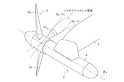
- FIG. 2 is a perspective view showing the undersea floating current generator according to each embodiment in use in the sea.
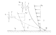
- FIG. 3 is a side view in the sea explaining passive control (PDC) of the position in the depth direction of the submerged ocean current power generator according to each embodiment.
- PDC passive control
- 4A and 4B are diagrams for explaining the principle of moment suppression control of the submerged ocean current generator according to the first embodiment.
- FIG. 4A is a diagram showing the relationship between thrust force and flow velocity
- FIG. 4B is thrust force. It is a figure which shows the relationship between the rotation speed of a rotary blade.
- FIG. 4A is a diagram showing the relationship between thrust force and flow velocity
- FIG. 4B is thrust force. It is a figure which shows the relationship between the rotation speed of a rotary blade.
- FIG. 5 is a perspective view of the main part of the floating body for explaining the parameters related to the moment suppression control of the submerged floating current generator according to the first embodiment.
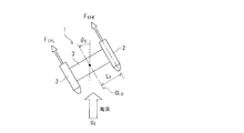
- FIG. 6 is a schematic plan view of a floating body for explaining parameters related to moment suppression control of the submerged floating current generator according to the first embodiment.
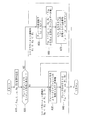
- FIG. 7 is a flowchart for explaining moment suppression control of the submerged floating ocean current power generator according to the first embodiment.
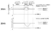
- 8A and 8B are time charts showing the effect of the moment suppression control of the submerged ocean current generator according to the first embodiment.
- FIG. 8A relates to the rotational speed (rotational speed) of the rotor blades
- FIG. 8B shows the thrust force. It is related.
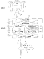
- FIG. 9B are diagrams showing a control system of the submerged floating current generator according to the second embodiment
- FIG. 9A is a configuration diagram showing the relationship between the two ocean current generator units
- FIG. 9B shows the control system It is a block diagram.
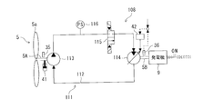
- FIG. 10 is a diagram showing a hydraulic circuit equipped in each ocean current power generation device main body of the undersea floating ocean current power generation device according to the second embodiment and its peripheral configuration.
- FIG. 11 is a flowchart illustrating the moment suppression control of the submerged floating ocean current power generator according to the second embodiment.
- FIG. 12 is a time chart showing the effect of moment suppression control of the submerged ocean current generator according to the second embodiment.
- FIG. 13 is a diagram showing a control system of the underwater floating current generator according to the third embodiment.
- FIG. 10 is a diagram showing a hydraulic circuit equipped in each ocean current power generation device main body of the undersea floating ocean current power generation device according to the second embodiment and its peripheral configuration.
- FIG. 11 is a flowchart
- FIG. 14 is a perspective view showing an underwater floating ocean current power generation apparatus according to the background art.
- FIG. 15 is a perspective view of a main part of a submerged floating ocean current power generation device for explaining a problem associated with a submarine floating ocean current power generation device.
- 16A to 16C are plan views of the submerged floating ocean current power generation device for explaining the problems associated with the submerged floating ocean current power generation device.
- FIG. 16A shows a normal state
- FIG. 16B shows a moment generated state
- 16C shows the behavior of the floating body due to the generation of moment.
- the ocean current power generator main body 2 is equipped with a generator 9 in a nacelle (also referred to as a pod) 4, and a rotating shaft 5A of a rotor blade 5 is connected to a rotor of the generator 9 (see FIGS. 1 and 9B). .
- the nacelle 4 is coupled to the left and right ends of the structure 3.
- the tip of the mooring line 6 is coupled to the center of the structure 3 in the left-right direction, and the base end of the mooring line 6 is locked to the seabed 7a (in this example, the anchor weight 6A of the seabed 7a).
- the floating body 1 floats in the sea in the horizontal direction and the vertical direction within a range restrained by the mooring line 6.
- the buoyancy of the floating body 1 is balanced on the left and right, and the structure 3 of the floating body 1 is formed in a wing shape so as to face the ocean current direction indicated by the white arrow in FIG. Thereby, the floating body 1 changes the direction according to the ocean current so that the front surface (the front surface of the rotary blade 5) faces the ocean current direction, and performs power generation while receiving the ocean current in front.
- each ocean current power generator main body 2 employs a downwind system in which the rotor blades 5 are arranged behind the nacelle 4 (downstream of the ocean current).
- the rotary blade 5 By arranging the rotary blade 5 on the downstream side of the nacelle 4 in this way, the front surface of the floating body 1 (the front surface of the rotary blade 5) can be easily directed in the ocean current direction.
- the nacelle 4 and the structure 3 are formed so as to be directed in the direction of the ocean current, and the front direction of the floating body 1 is set so as to passively face the ocean current direction.
- the floating body (sea floating type ocean current power generation device) 1 locked to the mooring line 6 floats in the sea.
- the floating body 1 has the acting force F wf of the ocean current applied to the floating body 1 and the buoyancy F generated in the floating body 1. and b, and position where the tensile force F t and the balance of the mooring lines 6 for locking the floating body 1 taken. That is, for the floating body 1, the buoyancy F b acts vertically upward, acting force F wf ocean current acts on ocean currents direction (horizontal direction), the tension F t mooring lines 6 of the buoyancy F b and ocean currents It acts so as to face the acting force F wf .
- the floating body 1 rises to a relatively shallow depth in the ocean, and the ocean current acting force F wf. Is strong (that is, if the ocean current velocity V wf ′ is high), the floating body 1 descends to a relatively deep depth in the sea 7 as indicated by reference numeral 1 ′. Further, the depth direction distribution of the current velocities V wf and V wf ′ becomes lower as the seabed 7a is approached near the seabed 7a, and becomes faster as it is separated from the seabed 7a.
- the floating body 1 descends in the sea 7 from the state indicated by the solid line in FIG. Balance at a moderately weakened depth.
- the current flow velocity is weaker than the state indicated by the solid line in FIG. 3
- the floating body 1 rises in the sea from the state indicated by the solid line, and the flow velocity is appropriately strengthened by the flow velocity distribution in the depth direction. Balance with depth.
- PDC Passive Depth Control
- each ocean current power generator main body 2 has a rotor blade 5 disposed behind the nacelle 4 (downstream of the ocean current), and the rotor blade 5 is disposed inside the nacelle 4.
- the main shaft 5 ⁇ / b> A, the speed increasers 8 and 108, and the generator 9 constitute drive trains 10 and 110 of each ocean current power generation device main body 2.
- the outer shape of the nacelle 4 has a smooth curved surface at the front end and the rear end, the intermediate portion is formed in a cylindrical shape, and the axis of the main shaft 5A is disposed on the axis CL1 of the outer shape of the nacelle 4.
- the outer shape of the nacelle 4 other shapes such as a spindle shape can be adopted.
- the rotary blade 5 is a two-blade equipped with two blades 5a with a phase difference of 180 degrees.
- the number of blades 5a of the rotary blade 5 is not limited to this, and other numbers such as three blades can be applied. Further, the blade 5a is simple and has a fixed pitch that does not require maintenance.
- Each of the submerged floating ocean current power generation devices of each embodiment has a function (moment suppression) that suppresses the generation of a moment in the floating body 1 due to the reduction of the thrust force when the blade 5a of the rotor blade 5 enters the shadow moment region.
- the control devices 20 and 120 having the means) are provided.
- the specific structure regarding moment suppression control differs, and the structure regarding moment suppression control of each embodiment is demonstrated below. This moment includes moments in any of roll, pitch, and yaw directions.
- the control device 20 of the present embodiment suppresses the decrease itself in the thrust current F th of the ocean current when the blade 5a enters the shadow area (shadow moment area) of the structure 3, and causes the floating body 1 to roll or pitch or Since the generation of the yaw moment M is suppressed, it has a function of a thrust force reduction suppressing means as a moment suppressing means.
- the control device 20 increases the rotational speed of the rotor blades 5 with a decrease in the ocean current flow velocity U C so as to suppress a decrease in thrust force.
- FIG. 4A is a characteristic diagram showing the relationship between the thrust force F th received from the ocean current and the current velocity U C when the blade 5a rotates at a constant rotation speed (rotation speed) ⁇ , and the blade 5a is constant.
- the thrust force F th received from the ocean current increases as the ocean current velocity U C increases.
- Figure 4B is a characteristic diagram showing the relationship between the blades 5a rotational speed of the thrust force F th and the blade 5a received from ocean currents when undergoing currents of constant flow rate U C (rotational speed) omega, the blade 5a is when undergoing currents of constant flow rate U C is thrust force F th received from ocean currents as the rotation number ⁇ of the blade 5a is increased becomes larger.
- the thrust force F th is reduced by decreasing the current flow velocity U C received by the blade 5a, the thrust force F th is increased by increasing the rotational speed ⁇ of the blade 5a.
- a decrease in force Fth can be suppressed.
- the blade 5a is because while the flow velocity U C ocean current the blade 5a is subjected to reduction contained in the shadow moment area, only during this time, if increasing the rotational speed ⁇ of the blade 5a, the currents in the shadow moment region
- the decrease in the thrust force F th due to the decrease in the flow velocity can be offset by the increase in the thrust force F th due to the increase in the rotational speed of the blade 5a.
- the control device 20 of the present embodiment includes a blade rotation area determination unit 21, a target rotation control unit 22, and a rotation increase control.
- the unit 23 and the drive train control unit 24 are respectively provided as functional elements.
- the control device 20 is individually provided in each ocean current power generator main body 2 and controls each ocean current power generator main body 2 independently. However, each ocean current power generator main body 2 controls the controller 20. You may make it control each ocean current power generator main body 2 independently, sharing.
- the blade rotation area determination unit 21 determines whether or not the blade 5a is in the shadow moment area. Specifically, the blade rotation region determination unit 21 reads the rotation angle (phase angle) ⁇ B of the blade 5a detected at a predetermined minute cycle by the blade rotation angle sensor 33 provided in the ocean current power generation device main body 2. Then, it is determined whether or not the blade 5a is in the rotation angle region ⁇ 0 to ⁇ 1 corresponding to the shadow moment region.
- the rotation angle ⁇ B of the blade 5a is an angle amount displaced in the rotation direction from a reference angle (not shown), and the angles ⁇ 0 and ⁇ 1 that define the rotation angle area corresponding to the shadow moment area (however, , ⁇ 0 ⁇ 1 ) is also an angle amount from the reference angle. It is determined whether or not the rotation angle ⁇ B of the blade 5a is between the approach angle ⁇ 0 to the shadow moment region and the escape angle ⁇ 1 from the shadow moment region ( ⁇ 0 ⁇ ⁇ B ⁇ ⁇ 1 ). judge.
- the rotation angle ⁇ B of the blade 5a is within the range of the angle ⁇ 0 to ⁇ 1 of the shadow moment region ( ⁇ 0 ⁇ ⁇ B ⁇ ⁇ 1 ), it is determined that the blade 5a is in the shadow moment region. If the rotation angle ⁇ B is outside the range of the angles ⁇ 0 to ⁇ 1 of the shadow moment region ( ⁇ B ⁇ 0 or ⁇ B > ⁇ 1 ), it is determined that the blade 5a is not in the shadow moment region.
- the target rotation control unit 22 determines the rotation speed of the blade 5a (that is, the blade 5) (hereinafter also referred to as blade rotation speed).
- the rotation increase control unit 23 controls the blade rotation speed ⁇ .
- the target rotation control unit 22 includes a load torque control unit 22a and a thrust force calculation unit 22b.
- the blade torque ⁇ detected by the rotation speed sensor 31 provided in the ocean current power generation device body 2 by the load torque control unit 22a becomes the target rotation number (target rotation speed) ⁇ 0. to calculate the load torque target value T DT of the drive train 10 output.
- the thrust force calculation unit 22b always calculates the thrust force Fth acting on the blade 5a (that is, the rotary blade 5).
- the target rotational speed ⁇ 0 is set in advance as the rotational speed at which the generator 9 can generate power most efficiently.
- If the blade rotational speed ⁇ is lower than the target rotational speed ⁇ 0 , the load torque target value T DT is increased by a predetermined amount (or the amount corresponding to the difference between ⁇ and ⁇ 0
- Thrust force calculating unit 22b flow velocity U C around the floating body 1 detected by the flow rate sensor 32 that is provided on ocean current power generation apparatus main body 2, and the blade rotation speed ⁇ detected by the rotational speed sensor 31, the blade rotation angle Based on the blade rotation angle ⁇ B detected by the sensor 33 and the rotation angle ⁇ F of the floating body 1 detected by the floating body rotation angle sensor 34 installed in the ocean current power generator main body 2, a table and map stored in advance are stored.
- the thrust force F th is calculated using an arithmetic expression (see the following expression (1)).
- F th f (U C, ⁇ , ⁇ B, ⁇ F) ⁇ (1)
- the flow velocity sensor 32 detects the flow velocity U C of the ocean current around the floating body 1 (particularly around the rotor blade 5).
- the floating body rotation angle sensor 34 detects the direction angle of the floating body 1 with respect to the direction of the ocean current (the direction angle of the center line CL0 of the floating body 1).
- the floating body rotation angle sensor 34 detects the direction angle of the floating body 1 by detecting the direction of the ocean current with respect to the floating body 1.
- the flow velocity sensor 32 and the floating body rotation angle sensor 34 may be applied with a sea current sensor that simultaneously detects the direction of the ocean current with respect to the floating body 1 and the flow velocity of the ocean current. Further, as shown in FIG. 6, when the left and right thrust forces F th are distinguished, the left thrust force is distinguished as F thL and the right thrust force is distinguished as F thR .
- the rotation increase control unit 23 includes a decrease flow rate calculation unit 23a, a rotation speed calculation unit 23b, and a load torque control unit 23c.
- the rotation increase control unit 23 calculates the current velocity U C ′ of the ocean current that decreases when the blade 5 a is in the shadow moment region, and the thrust force F th ′ at this velocity U C ′ is the target rotation control unit 22 most recently.
- the blade rotation speed ⁇ ′ is calculated so as to be equal to the thrust force F th calculated by the thrust force calculation unit 22b, and the blade rotation speed ⁇ ′ detected by the rotation speed sensor 31 is calculated as the blade rotation speed ⁇ ′. controlling the load torque T D of the drive train 10 such that.
- the reduced flow velocity calculation unit 23a calculates the flow velocity U C ′ of the ocean current when the blade 5a is in the shadow moment region by multiplying the flow velocity U C detected by the flow velocity sensor 32 by the shadow moment coefficient ⁇ . [Refer to the following formula (2)].
- the shadow moment coefficient ⁇ is determined by the shape of the structure 3 and the shape of the blade 5a.
- a uniform shadow moment coefficient ⁇ is applied in the shadow moment region, but in the shadow moment region, the flow velocity U C of the ocean current decreases at the boundary of the region (near the approach angle ⁇ 0 and the exit angle ⁇ 1 ).
- the thrust force F th is the current velocity U C ′ of the ocean current, the blade rotation speed ⁇ , the blade rotation angle ⁇ B, and the rotation angle of the floating body 1. focusing on the point that correlates with the theta F, the thrust force F th when a given velocity U C 'decreases the flow rate calculation unit 23a velocity U C of the computed currents in a' ocean current 'is the target rotation proximate
- the blade rotation speed (thrust force decrease suppression rotation speed or thrust force decrease suppression rotation speed) ⁇ ′ to be equal to the thrust force F th calculated by the thrust force calculation section 22b of the control section 22 is used using table data or the like. [Refer to the following formula (3)].
- the blade rotation speed ⁇ ′ in the shadow moment region is In order to recover the thrust force F th , the blade speed is set higher than the blade speed ⁇ controlled to the target speed ⁇ 0 outside the shadow moment region (see FIGS. 4A and 4B).
- the load torque target value T of the drive train 10 is set so that the blade rotational speed ⁇ detected by the rotational speed sensor 31 provided in the ocean current power generator main body 2 becomes the thrust force decrease suppression rotational speed ⁇ ′.
- the blade rotational speed ⁇ is controlled so as to become the thrust force reduction suppressing rotational speed ⁇ ′.
- the current velocity U C ′ of the ocean current when the blade 5a is in the shadow moment region is a value at the center portion of the shadow moment region, and when entering or exiting the shadow moment region (the rotation angle of the blade 5a) the theta when B is close to the entry angle theta 0 or escape angle theta 1), the flow rate of ocean currents that does not decrease until the calculated value U C ', and point to avoid abrupt change in the load torque T D during control switching,
- the load torque control unit 23c performs the processing with the control gain K to obtain the load torque target value TDT .
- Drive train control unit 24 controls the load torque (generation load torque) T D of the drive train 10 based load torque control section 22a, the load torque target value T DT calculated in either 23c.
- the blade to the target rotation number omega 0 of the generator 9 can generate electricity most efficiently
- the rotational speed ⁇ is controlled.
- the thrust force F th does not fluctuate even enters the blade 5a is the shadow moment region
- the blade rotational speed ⁇ is controlled to the thrust force decrease suppressing rotational speed ⁇ ′.
- the control device 20 suppresses the generation of moment in the floating body 1 as shown in the flowchart of FIG. Moment suppression control can be performed.
- the flowchart of FIG. 7 is implemented with a predetermined control cycle.
- the thrust force F th the current velocity U C of the ocean current, the blade rotation speed ⁇ , the rotation angle ⁇ B of the blade 5a, and the rotation angle ⁇ F of the floating body 1 are read (step A10).
- the thrust force F th the thrust force calculated and stored in the thrust force calculator 22b of the target rotation controller 22 in the most recent control cycle is read.
- the flow velocity sensor 32, rotation speed sensor 31, blade rotation angle sensor 33, and floating body rotation angle sensor 34 Read the latest detected value.
- step A20 Whether or not the blade 5a is in the shadow moment region by the blade rotation region determination unit 21, that is, the rotation angle ⁇ B of the blade 5a is within the angle range ⁇ 0 to ⁇ 1 of the shadow moment region ( ⁇ 0 ⁇ ⁇ B It is determined whether or not ⁇ ⁇ 1 (step A20). If it is determined that the blade 5a is not in the shadow moment area, the process proceeds to step A30. If it is determined that the blade 5a is in the shadow moment area, the process proceeds to step A50.
- Blade 5a shadow moment outside the region ( ⁇ B ⁇ 0 or ⁇ B> ⁇ 1) if the target rotation control unit 22 controls the load torque T D of drive train 10, calculates the thrust force F th. That is, the load torque control section 22a, the load blade rotation number omega is computed load torque target value T DT of the drive train 10 so that the target speed omega 0 is output, the drive train control unit 24, which is calculated Based on the torque target value TDT , the load torque of the drive train 10 is controlled (step A30).
- a thrust force Fth acting on the blade 5a is calculated (step A40).
- the calculated thrust force F th is stored in the memory of the control device 20 and is used as appropriate in the subsequent control cycles.
- the rotation increase control unit 23 controls the load torque T D of the drive train 10. That is, the reduced flow velocity calculation unit 23a multiplies the flow velocity U C by the shadow moment coefficient ⁇ to calculate the ocean current flow velocity U C ′ when the blade 5a is in the shadow moment region (the above equation (2)). (Step A50).
- the load torque control unit 23c is a blade rotational speed ⁇ is computed load torque target value T DT of the drive train 10 such that the thrust force decreases suppressing rotational speed Omega'.
- the flow velocity of the ocean current is reduced to the calculated value U C ′. no point, and the point of avoiding abrupt change in the load torque T D when the control switch, considering, was treated by the control gain K obtains the load torque target value T DT.
- the load torque target value TDT is reduced from the value calculated and set in step A30.
- the load torque target value TDT is obtained by processing with the control gain K so that this reduction is performed in a ramp shape.
- the blade rotational speed ⁇ decreases from the thrust force decrease suppression rotational speed ⁇ ′ to the target rotational speed ⁇ 0 , so that the load torque target value T DT increases.
- the load torque target value TDT is obtained by processing with the control gain K so that this increase is also performed in a ramp shape.
- the drive train control unit 24 thus controlling the load torque of the drive train 10 based on the calculated load torque target value T DT (step A70).
- the thrust force F th ′ acting on the blade 5a (rotary blade 5) is reduced, and the blade 5a is out of the shadow moment region ( ⁇ B ⁇ theta 0 or ⁇ B> ⁇ 1) is equal to the thrust force F th when it is in, it is possible to suppress the reduction itself thrust force F th as shown by the solid line in FIG. 8B.
- this control is not performed, the thrust force F th decreases as shown by a broken line in FIG. 8B.
- the thrust force F th is increased by the increase in the rotational speed of the blade 5a so as to offset the decrease in the thrust force F th due to the decrease in the ocean current flow velocity in the shadow moment region, thereby suppressing the decrease in the thrust force F th itself. Therefore, it is possible to suppress the moment M from being generated in the floating body 1 due to the decrease in the thrust force F th , and to suppress the occurrence of periodic vibration in the direction of the floating body due to this moment. it can. If this vibration occurs, there is a risk of damaging the structure 13, the blade 5a, the mooring line 6 and the like of the floating body 1, but this is avoided.
- the rotational phase of the blade 5a is controlled so that the blades 5a of the rotor blades 5 of the left and right ocean current power generation device main bodies 2 enter in synchronization with the shadow moment region of the shadow of the structure 3, and the left and right Since the generation of moments is suppressed by simultaneously reducing the thrust forces F thL and F thR (see FIG. 6), the rotational phase control unit functions as a moment suppression unit.
- the rotational phase control unit functions as a moment suppression unit.
- one of the left and right ocean current power generation device main bodies 2 is a master machine and the other is a slave machine, and the rotation phase of the blade 5a of the rotor blade 5 of the master machine is used as a reference phase.
- the blade 5a of the slave machine is controlled so that the rotational phase of the blade 5a of the rotor blade 5 of the slave machine follows and synchronizes with the reference phase.
- the control device 120 of the present embodiment includes an angular phase difference calculation unit 121, an angular phase difference determination unit 122, a synchronization hold control unit 123, a phase difference reduction control unit 124, A drive train control unit 125 is included as a functional element.
- the control device 120 is provided on the master machine side, a master signal (control amount) is output from the master machine side, and the phase response is made on the slave machine side, but the rotation of the blade 5a on the master machine side is performed. It is only necessary to follow the rotational phase of the blade 5a on the slave machine side with the phase as a main component, and the control device 120 itself may be provided on the slave machine side.
- Angular phase difference calculation unit 121 the blade rotation angle of the master machine and slave machine ocean current power generation apparatus blade rotation angle sensor 33a that is provided respectively on the body 2, the detected master machine blade rotation angle theta m and slave machines at 33b
- the difference (phase difference) ⁇ of ⁇ s is calculated as in the following equation (4).
- ⁇ ⁇ m ⁇ s (4)
- Angular phase difference determination unit 122 determines whether the blade 5a of the blade 5a and slave machine master unit from the phase difference ⁇ between the blade rotation angle ⁇ s of the blade rotation angle theta m and slave machine master unit is synchronous state Determine. That is, it is determined whether or not the phase difference ⁇ is within the allowable value ⁇ 0 that is 0 or a minute value close to 0 ( ⁇ ⁇ ⁇ 0 ). If the phase difference ⁇ is within the allowable value ⁇ 0, the synchronization state (position It is determined that there is no phase difference. Otherwise, it is determined that the state is asynchronous (with phase difference).
- the angular phase difference determination unit 122 when the blade rotation angle theta s of blade rotation angle theta m and slave machine master unit is determined is a synchronous state, the master machine blades 5a of the slave machine by synchronizing hold control section 123 blade Synchronous holding control is performed to keep the state synchronized with 5a.
- the phase difference determination unit 122 determines that the blade rotation angle ⁇ m of the master machine and the blade rotation angle ⁇ s of the slave machine are asynchronous
- the phase difference reduction control unit 124 sets the blade rotation angle ⁇ s of the slave machine as the master.
- the phase difference reduction control is performed so as to be synchronized with the blade 5a of the machine.
- the synchronization holding control unit 123 includes a load torque control unit 123a.
- machine based on the blade rotational speed omega s of, for calculating the load torque target value T DT1 of the drivetrain 110 of slave machine as blade rotational speed omega s of slave machine is equal to the blade rotation speed omega of the master unit output .
- the phase difference ⁇ is within the permissible value ⁇ 0 but only a small amount occurs, the phase difference ⁇ is brought close to 0 (the blade rotation speed ⁇ s of the slave machine becomes equal to the blade rotation speed ⁇ m of the master machine).
- the increase or decrease the load torque target value T DT1 as the load torque target value T DT1 is slowly changed in a ramp shape, the load torque control section 123a, the load torque target is treated by the control gain K 1 A value TDT1 is obtained.
- the phase difference reduction control unit 124 includes a slave rotation speed calculation unit 124a and a load torque control unit 124b.
- the slave rotation speed calculation unit 124a calculates a target value ⁇ s ′ of the blade rotation speed of the slave machine for setting the phase difference ⁇ to zero. Again, as the blade rotation speed omega of the slave machine is slowly changed in a ramp shape, the slave revolution calculating unit 124a, obtains the blade target value of the rotation speed omega s' is treated by the control gain K 2 I am doing so.
- the load torque target value TDT2 of the drive train 110 of the slave machine is calculated and output so that the blade rotational speed ⁇ s of the slave machine becomes equal to the target value ⁇ s ′ of the blade speed of the slave machine.
- the load torque control section 123a so that determining the load torque target value T DT2 is treated by the control gain K 1.
- the drive train control unit 125 is a load torque calculated by either the load torque target value TDT1 calculated by the load torque control unit 123a of the synchronization holding control unit 123 or the load torque control unit 124b of the phase difference reduction control unit 124. controlling the load torque (generation load torque) T D of the drive train 110 on the basis of the target value T DT2.
- the drive train 110 receives the rotating shaft (main shaft) 5A of the rotor blade 5, the speed increasing device 108 for increasing the rotational speed of the main shaft 5A, and the rotational force increased by the speed increasing device 108.
- the hydraulic power transmission mechanism is applied to the speed increaser 108. By operating the elements of the hydraulic power transmission mechanism, the gear ratio by the speed increaser 108 is increased. It can be changed.
- FIG. 10 is a hydraulic circuit diagram showing a hydraulic power transmission mechanism 108 that also functions as a speed increaser.
- the hydraulic circuit 111 includes a hydraulic pump 113 driven by the rotary shaft 5A of the rotor blade 5 in an oil passage 112, and A hydraulic motor 114 that rotates in response to hydraulic oil discharged from the hydraulic pump 113, an on-off valve 115 interposed in a portion of the oil passage 112 from the hydraulic pump 113 toward the hydraulic motor 114, and a hydraulic pump 113 in the oil passage 112. Is provided with a pressure sensor 116 provided at a portion from the head toward the hydraulic motor 114.
- the hydraulic motor 114 is a swash plate type hydraulic motor that can change the rotational speed even if the input hydraulic pressure does not change by adjusting the swash plate angle, and the rotational shaft 5B of the hydraulic motor 114 detected by the rotational speed sensor 36 is applied.
- the hydraulic motor 114 can be adjusted to a desired rotation speed state by feeding back the rotation speed (the number of rotations) and adjusting the swash plate angle by the swash plate angle adjustment unit 42.
- the rotating shaft 5B of the hydraulic motor 114 is connected to the generator 9.
- the load torque of the hydraulic motor 114 can be adjusted by adjusting the swash plate angle of the hydraulic motor 114, and the load torque of the hydraulic motor 114 can be grasped by the hydraulic oil pressure detected by the pressure sensor 116. Can do.
- the load torque of the drive train 110 can be adjusted by adjusting the swash plate angle of the hydraulic motor 114, and the swash plate angle of the hydraulic motor 14 is adjusted according to the load torque target values TDT1 and TDT2. load torque (generation load torque) T D of train 110 is controlled.
- the rotating shaft 5 ⁇ / b> A of the rotor blade 5 is equipped with a speed governor 35 and a mechanical brake 41, and the rotational speed of the rotor blade 5 is stabilized by the speed governor 35.
- the rotation of the rotary blade 5 can be regulated.
- the control device 120 suppresses the generation of moment in the floating body 1 as shown in the flowchart of FIG. 11, for example. Moment suppression control can be performed.
- the flowchart of FIG. 11 is implemented with a predetermined control cycle.
- step B10 it reads a blade rotation angle sensor 33a, of the detected master unit at 33b blade rotation angle theta m and slave machine blade rotation angle theta s (step B10). Then, the difference (phase difference) ⁇ between the blade rotation angle ⁇ m of the master machine and the blade rotation angle ⁇ s of the slave machine is calculated by the angular phase difference calculation unit 121 [see the above formula (4)] (step B20). .
- step B20 the phase difference ⁇ calculated in step B20 is compared with the preset allowable value ⁇ 0 by the angular phase difference determination unit 122, and the blade 5a of the master machine and the blade 5a of the slave machine are in a synchronized state. It is determined whether (
- the load torque target value TDT1 of the drive train 110 of the slave machine is calculated and output so that the blade rotational speed ⁇ s of the slave machine becomes equal to the blade rotational speed ⁇ m of the master machine.
- processing is performed with the control gain K 1 to obtain the load torque target value T DT1 so that the load torque target value T DT2 is gradually changed into a ramp shape.
- the drive train control unit 125 controls the load torque (generation load torque) T D of the drive train 110 on the basis of the load torque target value T DT2.
- the slave rotational speed calculation unit 124a calculates a target value ⁇ s ′ of the blade rotational speed of the slave machine for setting the phase difference ⁇ to zero. Again, as the blade rotation speed omega s slave machine is slowly changed in a ramp shape, the slave revolution calculating unit 124a, the control of the blade rotation speed is treated with a gain K 2 target values omega s' Obtain (step B50).
- the blade rotational speed ⁇ s of the slave machine is determined by the load torque control unit 124b.
- the load torque target value TDT2 of the drive train 110 of the slave machine is calculated and output so as to be equal to the target value ⁇ s ′ of the blade speed of the slave machine.
- the load torque control section 123a controls the load torque (generation load torque) T D of the drive train 110 on the basis of the load torque target value T DT2 (step B60).
- FIG. 12 is a time chart showing the transition of the blade rotation angle (blade angle) ⁇ B for explaining the phase difference reduction control and the synchronization maintaining control.
- the solid line shows the blade rotation angle ⁇ B of the master machine, and the broken line shows The blade rotation angle ⁇ B of the slave machine is shown.
- FIG. 11 when it is judged that an asynchronous state by the angular phase difference determination unit 122, position and blade rotation angle theta B slave device by the phase difference reduction control approaches gradually to the blade rotation angle theta B of the master unit After the phase difference is eliminated, the state without synchronization (synchronized state) is maintained in the synchronization maintaining control.
- the blades 5a enters the shadow moment area of the shadow of the structure.
- the thrust forces F thL and F thR decrease at the same time in the left and right ocean current power generation device bodies 2, so the generation of moment is suppressed even if the thrust force decreases. It is possible to suppress the occurrence of periodic vibration in the direction of the floating body 1. If this vibration occurs, there is a risk of damaging the structure 13, the blade 5a, the mooring line 6 and the like of the floating body 1, but this is avoided.
- the blades 5a of the rotor blades 5 of the left and right ocean current power generation device main bodies 2 are moved in synchronization with the shadow moment area of the shadow of the structure 3 so as to enter. Since the generation of moment is suppressed by controlling the rotation phase and simultaneously generating a decrease in the left and right thrust forces, it has the function of a rotation phase control means as a moment suppression means.
- the ocean current power generation device main body 2 is a slave device, and a master signal (control amount) is output from a separately provided master device 200, and the blades of the left and right ocean current power generation device main bodies 2 are output. 5a is controlled. In the slave machine (left and right ocean current power generation device main body 2), this is responded by adjusting the phase of the rotation angle of the blade 5a.
- the master machine 200 is equipped with a control device 120 similar to that of the second embodiment [see FIG. 9B] in order to control the left and right ocean current power generation device main bodies 2 respectively.
- the control device 120 includes an angular phase difference calculation unit 121, an angular phase difference determination unit 122, a synchronization hold control unit 123, a phase difference reduction control unit 124, and a drive train control unit 125. Each has a functional element. In addition, you may provide the control apparatus 120 itself in the hydroelectric generator main body 2 of not only the master machine 200 but a slave machine.
- the master machine 200 stores a reference phase serving as a reference for manipulating the rotation phase and the rotation speed (rotation speed) of the blade 5a (rotary blade 5) of each flow power generator main body 2 of the slave machine.
- This reference phase defines a target value of the rotation angle (phase) of the blade 5 a according to the time axis, and in particular, the reference phase is set based on the target rotation speed of the rotor of the generator 9.
- the target rotational speed of the rotor of the generator 9 is obtained from an ideal power generation state in which a power generation amount can be obtained efficiently.
- the reference phase for controlling the rotation of the blades 5a of each flow power generator main body 2 is based on the target rotational speed of the rotor of the generator 9. Since it is set, there is also an effect that the power generation amount can be efficiently obtained with the generator 9 in an ideal power generation state.
- the rotation phase of the blades 5a of the rotor blades 5 of the master machine is used as the reference phase.
- This reference phase is also the target rotation speed (efficiency of the rotor of the generator 9) as in the third embodiment. It may be set on the basis of an ideal power generation state in which a power generation amount is often obtained.
- the suppressing decrease of thrust force by controlling the rotational speed of the blades 5a by controlling the load torque T D of the drive train if there is no need to consider maintenance, etc.
- the blade 5a may be configured as a variable pitch type, and the rotational speed of the blade 5a may be controlled by changing the pitch to suppress the reduction of the thrust force.
- the hydraulic motor, load adjustment other than the swash plate control it may be applied capable, also, irrespective of the hydraulic power transmission mechanism, like the first embodiment, may control the load torque T D of the drive train through the power generation load torque of the generator.
Landscapes
- Engineering & Computer Science (AREA)
- Chemical & Material Sciences (AREA)
- Combustion & Propulsion (AREA)
- Mechanical Engineering (AREA)
- General Engineering & Computer Science (AREA)
- Life Sciences & Earth Sciences (AREA)
- General Life Sciences & Earth Sciences (AREA)
- Oceanography (AREA)
- Power Engineering (AREA)
- Other Liquid Machine Or Engine Such As Wave Power Use (AREA)
Abstract
Description
(3)前記スラスト力減少抑制手段は、前記ブレードが前記構造物の影の領域に進入した際の海流の流速低下に伴って前記回転翼ロータの回転速度を上昇させてスラスト力の減少を抑制することが好ましい。
(7)前記基準位相は、前記発電機のロータの目標回転速度に基づいて設定されていることが好ましい。
(12)前記スラスト力の減少抑制は、前記ブレードが前記構造物の影の領域に進入した際に、前記影の領域の海流の流速低下に伴って前記回転翼の回転速度を上昇させることにより実施することが好ましい。
(16)前記基準位相は、前記発電機のロータの目標回転速度に基づいて設定されていることが好ましい。
まず、各実施形態の海中浮遊式海流発電装置の概略構成を説明すると、海中浮遊式海流発電装置の概略は、背景技術において説明したもの(図14参照)と同様である。説明が重複するが、この海中浮遊式海流発電装置は浮体1として構成され、浮体1は、図2に示すように、2つの海流発電装置本体2,2とこれらを接続する構造物3とから一つの浮体1を構成した双胴型を採用している。海流発電装置本体2は、ナセル(ポッドとも呼ぶ)4内に発電機9を装備し、この発電機9のロータに回転翼5の回転軸5Aが接続されている(図1,図9B参照)。
〔モーメント抑制制御系の構成〕
本実施形態の制御装置20は、ブレード5aが構造物3の影の領域(シャドウモーメント領域)に進入した際の海流のスラスト力Fthの減少自体を抑制して、浮体1にロールもしくはピッチもしくはヨーモーメントMが発生することを抑制するので、モーメント抑制手段としてのスラスト力減少抑制手段の機能を有する。制御装置20は、海流の流速UCの減少に伴って回転翼5の回転速度を上昇させてスラスト力の減少を抑制するようにしている。
Fth=f(UC,ω,θB,θF)・・・(1)
UC´=UC×α・・・(2)
Fth´=f(UC´,ω´,θB,θF)=Fth・・・(3)
第1実施形態にかかる海中浮遊式海流発電装置は、上述のように構成されているので、制御装置20により、例えば図7のフローチャートに示すように、浮体1にモーメントが発生するのを抑制するモーメント抑制制御を実施することができる。なお、図7のフローチャートは所定の制御周期で実施される。
これにより、ブレード5aがシャドウモーメント領域内(θ0≦θB≦θ1)にある場合にブレード5a(回転翼5)に作用するスラスト力Fth´が、ブレード5aがシャドウモーメント領域外(θB<θ0又はθB>θ1)にある場合のスラスト力Fthと等しくなり、図8Bに実線で示すようにスラスト力Fthの減少自体を抑制することができる。本制御を実施しない場合には、図8Bに破線で示すようにスラスト力Fthは減少する。
〔モーメント抑制制御系の構成〕
本実施形態では、左右の海流発電装置本体2の各々の回転翼5のブレード5aが構造物3の影のシャドウモーメント領域に同期して進入するようにブレード5aの回転位相を制御して、左右のスラスト力FthL,FthR(図6参照)の低下を同時に発生させることにより、モーメントの発生を抑制するので、モーメント抑制手段としての回転位相制御手段の機能を有する。特に、本実施形態では、図9Aに示すように、左右の海流発電装置本体2の一方をマスタ機とし他方をスレイブ機として、マスタ機の回転翼5のブレード5aの回転位相を基準位相としてこの基準位相にスレイブ機の回転翼5のブレード5aの回転位相が追従して同期するようにスレイブ機のブレード5aを制御する。
δθ=θm-θs・・・(4)
スレイブ回転数演算部124aは、位相差δθを0にするためのスレイブ機のブレード回転数の目標値ωs´を演算する。この場合も、スレイブ機のブレード回転数ωが緩やかにランプ状に変更されるように、スレイブ回転数演算部124aでは、制御ゲインK2により処理してブレード回転数の目標値ωs´を求めるようにしている。
第2実施形態にかかる海中浮遊式海流発電装置は、上述のように構成されているので、制御装置120により、例えば図11のフローチャートに示すように、浮体1にモーメントが発生するのを抑制するモーメント抑制制御を実施することができる。なお、図11のフローチャートは所定の制御周期で実施される。
〔モーメント抑制制御系の構成〕
本実施形態では、第2実施形態と同様に、左右の海流発電装置本体2の各々の回転翼5のブレード5aが構造物3の影のシャドウモーメント領域に同期して進入するようにブレード5aの回転位相を制御して、左右のスラスト力の低下を同時に発生させることにより、モーメントの発生を抑制するので、モーメント抑制手段としての回転位相制御手段の機能を有する。本実施形態では、図13に示すように、海流発電装置本体2を何れもスレイブ機として、マスタ信号(制御量)は別途設けたマスタ機200から出力され、左右の海流発電装置本体2のブレード5aを制御する。スレイブ機(左右の海流発電装置本体2)ではブレード5aの回転角度の位相調整でこれ応答するようになっている。
第3実施形態にかかる海中浮遊式海流発電装置は、上述のように構成されているので、スレイブ機である各流発電装置本体2のブレード5aの回転が、第2実施形態のスレイブ機と同様に制御されて、第2実施形態のものと同様の作用及び効果を得ることができる。なお、各流発電装置本体2のブレード5aの制御は、図11のフローチャートに示すように実施することができる。
以上、本発明の実施形態を説明したが、本発明は、その趣旨を逸脱しない範囲で、かかる実施形態を適宜変更したり、組み合わせたりして実施することができる。
例えば、第2実施形態ではマスタ機の回転翼5のブレード5aの回転位相を基準位相としているが、この基準位相についても第3実施形態と同様に、発電機9のロータの目標回転速度(効率よく発電量が得られる理想的な発電状態から求められる)に基づいて設定してもよい。
2 海流発電装置本体
3 構造物
4 ナセル(ポッド)
5 回転翼
5A 主軸(回転翼5の回転軸)
5a ブレード
6 係留索
6A アンカーウェイト
7 海中
7a 海底
8 増速機
9 発電機
10,110 ドライブトレーン
20 制御装置(モーメント抑制手段としてのスラスト力減少抑制手段)
21 ブレード回転領域判定部
22 目標回転制御部
22a 負荷トルク制御部
22b スラスト力演算部
23 回転増加制御部
23a 低下流速演算部
23b 回転速度演算部
23c 負荷トルク制御部
24 ドライブトレーン制御部
31,31a,31b 回転速度センサ
32 流速センサ
33,33a,33b ブレード回転角度センサ
34 浮体回転角度センサ
108 増速機としての油圧式動力伝達機構
111 油圧回路
112 油路
113 油圧ポンプ
114 油圧モータ
115 開閉弁
116 圧力センサ
120 制御装置(モーメント抑制手段としての回転位相制御手段)
121 角位相差演算部
122 角位相差判定部
123 同期保持制御部
123a 負荷トルク制御部
124 位相差低減制御部
124a スレイブ回転数演算部
124b 負荷トルク制御部
125 ドライブトレーン制御部
Fth スラスト力
Fwf 海流の作用力
Fb 浮体1の浮力
Ft 係留索6の張力
M モーメント
TD 負荷トルク
TDT,TDT1、TDT2 負荷トルク目標値
UC 海流の流速
ω ブレード5aの回転数(回転速度)
ω0 目標回転数(目標回転速度)
ω´ スラスト力低減抑制回転数(スラスト力低減抑制回転速度)
θB ブレード5aの回転角度(位相角度)
θ0~θ1 シャドウモーメント領域に対応する回転角度領域
θF 浮体1の回転角度
Claims (18)
- ナセル内に収納された発電機のロータを前記ナセルの外部に突出した回転翼により駆動する海流発電装置本体が構造物の左右に結合されて、海中を浮遊可能な双胴型の浮体として構成され、前記構造物の左右中間部を係留索によって海底に係止されて使用される海中浮遊式海流発電装置であって、
前記海流発電装置本体には、前記回転翼を前記ナセルよりも海流方向の下流側に配置したダウンウィンド方式が用いられ、
前記回転翼のブレードが海流方向の上流側の前記構造物の影の領域に進入した際の海流の流速低下に伴うスラスト力の減少によって前記浮体に発生するモーメントを抑制するモーメント抑制手段を備えている
ことを特徴とする海中浮遊式海流発電装置。 - 前記モーメント抑制手段は、前記ブレードが前記構造物の影の領域に進入した際の海流の前記スラスト力の減少を抑制するスラスト力減少抑制手段である
ことを特徴とする請求項1記載の海中浮遊式海流発電装置。 - 前記スラスト力減少抑制手段は、前記ブレードが前記構造物の影の領域に進入した際の海流の流速低下に伴って前記回転翼の回転速度を上昇させてスラスト力の減少を抑制する
ことを特徴とする請求項2記載の海中浮遊式海流発電装置。 - 前記モーメント抑制手段は、左右の前記海流発電装置本体の各々の前記回転翼の前記ブレードが前記構造物の影の領域に同期して進入するように前記ブレードの回転位相を制御する回転位相制御手段である
ことを特徴とする請求項1記載の海中浮遊式海流発電装置。 - 前記回転位相制御手段は、左右の前記海流発電装置本体の一方の前記回転翼の前記ブレードの回転位相を基準位相とし前記基準位相に他方の前記回転翼の前記ブレードの回転位相が追従して同期するように前記ブレードの回転位相を制御する
ことを特徴とする請求項4記載の海中浮遊式海流発電装置。 - 前記回転位相制御手段は、予め設定された基準位相に基づいて、左右の前記海流発電装置本体の各々の前記回転翼の前記ブレードの回転位相を制御する
ことを特徴とする請求項4記載の海中浮遊式海流発電装置。 - 前記基準位相は、前記発電機のロータの目標回転速度に基づいて設定されている
ことを特徴とする請求項5又は6記載の海中浮遊式海流発電装置。 - 前記スラスト力減少抑制手段は、
前記ブレードが前記構造物の影の領域に入っているか否かを判定するブレード回転領域判定部と、
前記ブレードが前記構造物の影の領域に入っていない場合に、前記ブレードの回転速度を目標回転速度に制御する目標回転制御部と、
前記ブレードが前記構造物の影の領域に入っている場合に、海流の流速低下によるスラスト力の減少を抑制するように回転増加させたブレードのスラスト力減少抑制回転速度を設定し、前記ブレードの回転速度を前記スラスト力減少抑制回転速度に制御する回転増加制御部と、を有している
ことを特徴とする請求項3記載の海中浮遊式海流発電装置。 - 前記回転位相制御手段は、
前記基準位相と制御対象の前記ブレードの回転位相との位相差を演算する角位相差演算部と、
演算された前記位相差から制御対象の前記ブレードの回転位相が前記基準位相と同期した同期状態であるか否かを判定する角位相差判定部と、
前記同期状態であると判定されたら前記同期状態を保持する同期保持制御部と、
前記同期状態でないと判定されたら前記位相差を低減して前記同期状態になるように制御する位相差低減制御部と、を有している
ことを特徴とする請求項7記載の海中浮遊式海流発電装置。 - ナセル内に収納された発電機のロータを前記ナセルの外部に突出した回転翼により駆動する海流発電装置本体が構造物の左右に結合されて、海中を浮遊可能な双胴型の浮体として構成され、前記構造物の左右中間部を係留索によって海底に係止されて使用され、前記海流発電装置本体には、前記回転翼を前記ナセルよりも海流方向の下流側に配置したダウンウィンド方式が用いられた海中浮遊式海流発電装置の制御方法であって、
前記回転翼のブレードが海流方向の上流側の前記構造物の影の領域に進入した際に、前記影の領域の海流の流速低下に伴うスラスト力の減少によって前記浮体に発生するモーメントを抑制するモーメント抑制処理を実施する
ことを特徴とする海中浮遊式海流発電装置の制御方法。 - 前記モーメント抑制処理は、前記ブレードが前記構造物の影の領域に進入した際に、前記影の領域の海流の前記スラスト力の減少を抑制することにより実施する
ことを特徴とする請求項10記載の海中浮遊式海流発電装置の制御方法。 - 前記スラスト力の減少抑制は、前記ブレードが前記構造物の影の領域に進入した際に、前記影の領域の海流の流速低下に伴って前記回転翼の回転速度を上昇させることにより実施する
ことを特徴とする請求項11記載の海中浮遊式海流発電装置の制御方法。 - 前記モーメント抑制処理は、左右の前記海流発電装置本体の各々の前記回転翼の前記ブレードが前記構造物の影の領域に同期して進入するように前記ブレードの回転位相を制御することにより実施する
ことを特徴とする請求項10記載の海中浮遊式海流発電装置の制御方法。 - 前記回転位相の制御は、左右の前記海流発電装置本体の一方の前記回転翼の前記ブレードの回転位相を基準位相とし前記基準位相に他方の前記回転翼の前記ブレードの回転位相が追従して同期するようにして実施する
ことを特徴とする請求項13記載の海中浮遊式海流発電装置の制御方法。 - 前記回転位相の制御は、予め設定された基準位相に基づいて、左右の前記海流発電装置本体の各々の前記回転翼の前記ブレードの回転位相を制御することにより実施する
ことを特徴とする請求項13記載の海中浮遊式海流発電装置の制御方法。 - 前記基準位相は、前記発電機のロータの目標回転速度に基づいて設定されている
ことを特徴とする請求項14又は15記載の海中浮遊式海流発電装置の制御方法。 - 前記スラスト力の減少抑制は、
前記ブレードが前記構造物の影の領域に入っているか否かを判定し、
前記ブレードが前記構造物の影の領域に入っていないと判定されたら、前記ブレードの回転速度を目標回転速度に制御する目標回転制御部と、
前記ブレードが前記構造物の影の領域に入っている場合に、海流の流速低下によるスラスト力の減少を抑制するように回転増加させたブレードのスラスト力減少抑制回転速度を設定し、前記ブレードの回転速度を前記スラスト力減少抑制回転速度に制御する
ことを特徴とする請求項12記載の海中浮遊式海流発電装置の制御方法。 - 前記回転位相の制御は、
前記基準位相と制御対象の前記ブレードの回転位相との位相差を演算し、
演算された前記位相差から制御対象の前記ブレードの回転位相が前記基準位相と同期した同期状態であるか否かを判定し、
前記同期状態であると判定されたら前記同期状態を保持し、
前記同期状態でないと判定されたら前記位相差を低減して前記同期状態になるように制御する
ことを特徴とする請求項16記載の海中浮遊式海流発電装置の制御方法。
Priority Applications (6)
| Application Number | Priority Date | Filing Date | Title |
|---|---|---|---|
| CN201580058652.3A CN107076103B (zh) | 2014-10-29 | 2015-10-20 | 海中漂浮式海流发电装置及其控制方法 |
| BR112017008793A BR112017008793A2 (pt) | 2014-10-29 | 2015-10-20 | dispositivo de geração de energia a partir da corrente oceânica do tipo flutuante submerso |
| US15/523,085 US10584675B2 (en) | 2014-10-29 | 2015-10-20 | Underwater floating-type ocean current power generation device |
| GB1706444.5A GB2545871A (en) | 2014-10-29 | 2015-10-20 | Underwater floating-type ocean current power generation device |
| KR1020177011532A KR20170065601A (ko) | 2014-10-29 | 2015-10-20 | 해중 부유식 해류 발전 장치 |
| DE112015004928.2T DE112015004928T5 (de) | 2014-10-29 | 2015-10-20 | Schwimmende Unterwasser-Meeresströmungsstromerzeugungsvorrichtung |
Applications Claiming Priority (2)
| Application Number | Priority Date | Filing Date | Title |
|---|---|---|---|
| JP2014219942A JP6358927B2 (ja) | 2014-10-29 | 2014-10-29 | 海中浮遊式海流発電装置 |
| JP2014-219942 | 2014-10-29 |
Publications (1)
| Publication Number | Publication Date |
|---|---|
| WO2016067971A1 true WO2016067971A1 (ja) | 2016-05-06 |
Family
ID=55857312
Family Applications (1)
| Application Number | Title | Priority Date | Filing Date |
|---|---|---|---|
| PCT/JP2015/079566 Ceased WO2016067971A1 (ja) | 2014-10-29 | 2015-10-20 | 海中浮遊式海流発電装置 |
Country Status (8)
| Country | Link |
|---|---|
| US (1) | US10584675B2 (ja) |
| JP (1) | JP6358927B2 (ja) |
| KR (1) | KR20170065601A (ja) |
| CN (1) | CN107076103B (ja) |
| BR (1) | BR112017008793A2 (ja) |
| DE (1) | DE112015004928T5 (ja) |
| GB (1) | GB2545871A (ja) |
| WO (1) | WO2016067971A1 (ja) |
Families Citing this family (9)
| Publication number | Priority date | Publication date | Assignee | Title |
|---|---|---|---|---|
| JP6248017B2 (ja) * | 2014-09-12 | 2017-12-13 | 三菱重工業株式会社 | 海流発電装置の起動方法及び起動制御装置 |
| JP6207092B2 (ja) * | 2015-02-17 | 2017-10-04 | 三菱重工業株式会社 | 水流発電機 |
| JP6786907B2 (ja) * | 2016-06-28 | 2020-11-18 | 株式会社Ihi | 水中浮遊式発電装置の姿勢制御システムおよび姿勢制御方法 |
| CN106939873B (zh) * | 2017-02-25 | 2018-12-14 | 荣成市华慧新能源科技有限公司 | 一种潜水潮汐海流发电站 |
| JP6907715B2 (ja) * | 2017-05-30 | 2021-07-21 | 株式会社Ihi | 水中浮遊式発電装置の姿勢制御システムおよび姿勢制御方法 |
| JP6926932B2 (ja) * | 2017-10-18 | 2021-08-25 | 株式会社Ihi | 水中浮遊式発電装置の姿勢制御システム |
| JP6988609B2 (ja) * | 2018-03-16 | 2022-01-05 | 株式会社Ihi | 制御装置、水流発電システム、及び水流発電装置の制御方法 |
| JP7139903B2 (ja) * | 2018-11-15 | 2022-09-21 | 株式会社Ihi | 海中浮遊式海流発電装置及び海中浮遊式海流発電システム |
| WO2020125885A1 (en) * | 2018-12-20 | 2020-06-25 | Vestas Wind Systems A/S | Correcting pitch angle |
Citations (4)
| Publication number | Priority date | Publication date | Assignee | Title |
|---|---|---|---|---|
| JP2010531956A (ja) * | 2007-06-29 | 2010-09-30 | アクアンティス,エル.エル.シー. | マルチポイント係留及び安定化システム、及び流れを用いた水中用タービンのための制御方法 |
| JP2014005766A (ja) * | 2012-06-22 | 2014-01-16 | Toshiba Corp | 水流発電装置 |
| JP2014159750A (ja) * | 2013-02-19 | 2014-09-04 | Ihi Corp | 海流発電装置 |
| WO2014163141A1 (ja) * | 2013-04-03 | 2014-10-09 | 株式会社Ihi | 水中機器 |
Family Cites Families (6)
| Publication number | Priority date | Publication date | Assignee | Title |
|---|---|---|---|---|
| US6091161A (en) * | 1998-11-03 | 2000-07-18 | Dehlsen Associates, L.L.C. | Method of controlling operating depth of an electricity-generating device having a tethered water current-driven turbine |
| US6923622B1 (en) * | 2002-03-07 | 2005-08-02 | Clipper Windpower Technology, Inc. | Mechanism for extendable rotor blades for power generating wind and ocean current turbines and means for counter-balancing the extendable rotor blade |
| US8766466B2 (en) * | 2011-10-31 | 2014-07-01 | Aquantis, Inc. | Submerged electricity generation plane with marine current-driven rotors |
| JP5626257B2 (ja) * | 2012-04-12 | 2014-11-19 | 株式会社安川電機 | 発電装置 |
| WO2014175227A1 (ja) * | 2013-04-22 | 2014-10-30 | 株式会社Ihi | 水中機器及び水中機器の姿勢制御方法 |
| JP6207092B2 (ja) * | 2015-02-17 | 2017-10-04 | 三菱重工業株式会社 | 水流発電機 |
-
2014
- 2014-10-29 JP JP2014219942A patent/JP6358927B2/ja not_active Expired - Fee Related
-
2015
- 2015-10-20 KR KR1020177011532A patent/KR20170065601A/ko not_active Withdrawn
- 2015-10-20 GB GB1706444.5A patent/GB2545871A/en not_active Withdrawn
- 2015-10-20 US US15/523,085 patent/US10584675B2/en not_active Expired - Fee Related
- 2015-10-20 DE DE112015004928.2T patent/DE112015004928T5/de not_active Withdrawn
- 2015-10-20 WO PCT/JP2015/079566 patent/WO2016067971A1/ja not_active Ceased
- 2015-10-20 BR BR112017008793A patent/BR112017008793A2/pt not_active IP Right Cessation
- 2015-10-20 CN CN201580058652.3A patent/CN107076103B/zh not_active Expired - Fee Related
Patent Citations (4)
| Publication number | Priority date | Publication date | Assignee | Title |
|---|---|---|---|---|
| JP2010531956A (ja) * | 2007-06-29 | 2010-09-30 | アクアンティス,エル.エル.シー. | マルチポイント係留及び安定化システム、及び流れを用いた水中用タービンのための制御方法 |
| JP2014005766A (ja) * | 2012-06-22 | 2014-01-16 | Toshiba Corp | 水流発電装置 |
| JP2014159750A (ja) * | 2013-02-19 | 2014-09-04 | Ihi Corp | 海流発電装置 |
| WO2014163141A1 (ja) * | 2013-04-03 | 2014-10-09 | 株式会社Ihi | 水中機器 |
Also Published As
| Publication number | Publication date |
|---|---|
| KR20170065601A (ko) | 2017-06-13 |
| BR112017008793A2 (pt) | 2017-12-26 |
| DE112015004928T5 (de) | 2017-07-13 |
| CN107076103A (zh) | 2017-08-18 |
| GB201706444D0 (en) | 2017-06-07 |
| CN107076103B (zh) | 2019-07-09 |
| GB2545871A (en) | 2017-06-28 |
| JP6358927B2 (ja) | 2018-07-18 |
| US20170314525A1 (en) | 2017-11-02 |
| US10584675B2 (en) | 2020-03-10 |
| JP2016084793A (ja) | 2016-05-19 |
Similar Documents
| Publication | Publication Date | Title |
|---|---|---|
| JP6358927B2 (ja) | 海中浮遊式海流発電装置 | |
| CN104271944B (zh) | 浮动风力涡轮机的协调控制 | |
| EP2935876B1 (en) | Controlling motions of floating wind turbines | |
| US8219257B2 (en) | Power control protocol for a hydrokinetic device including an array thereof | |
| CA2693802C (en) | Wind turbine generator and yaw rotation control method for wind turbine generator | |
| CN102575646B (zh) | 在风力涡轮机装置中提取波浪能 | |
| US10024303B2 (en) | Method and device for controlling floating body wind turbine power generating apparatus, and floating body wind turbine power generating apparatus | |
| US20120319406A1 (en) | Method for Operating a Wave Energy Converter and Wave Energy Converter | |
| KR20100047810A (ko) | 해저 발전소의 전력 조절 방법 및 장치 | |
| JP2008019865A (ja) | 循環的波エネルギー変換システム | |
| US20140202146A1 (en) | Method for operating a wave energy converter | |
| GB2450077A (en) | Turbine for tidal power generation with active control of blade pitch | |
| WO2011091448A2 (en) | Method of counteracting the tendency of a tethered electricity water current-driven turbine to dive when power is produced | |
| JP6786907B2 (ja) | 水中浮遊式発電装置の姿勢制御システムおよび姿勢制御方法 | |
| EP3054152B1 (en) | Wind power generation apparatus | |
| WO2016135800A1 (ja) | 発電システム | |
| JP2014231785A (ja) | 浮体式風力発電装置 | |
| JP6248017B2 (ja) | 海流発電装置の起動方法及び起動制御装置 | |
| US20250084817A1 (en) | Turbine Assembly, System and Method | |
| EP2656499B1 (en) | Control of water current turbines | |
| JP2018127907A (ja) | 水中浮遊式発電装置の起動方法、水中浮遊式発電装置の停止方法及び水中浮遊式発電システム | |
| JP2017020420A (ja) | 浮遊式水中発電装置の姿勢制御システムおよび姿勢制御方法 | |
| TW202432950A (zh) | 用於操作浮動式風力渦輪機的系統及方法、浮動式風力渦輪機、風場、電腦程式產品及電腦可讀儲存媒體 | |
| Usui et al. | Counter-Rotating Type Tidal Stream Power Unit Moored by Only One Cable | |
| JP2024532751A (ja) | 浮体式風力タービンの動作を停止させる方法 |
Legal Events
| Date | Code | Title | Description |
|---|---|---|---|
| 121 | Ep: the epo has been informed by wipo that ep was designated in this application |
Ref document number: 15855749 Country of ref document: EP Kind code of ref document: A1 |
|
| ENP | Entry into the national phase |
Ref document number: 201706444 Country of ref document: GB Kind code of ref document: A Free format text: PCT FILING DATE = 20151020 |
|
| ENP | Entry into the national phase |
Ref document number: 20177011532 Country of ref document: KR Kind code of ref document: A |
|
| WWE | Wipo information: entry into national phase |
Ref document number: 15523085 Country of ref document: US |
|
| WWE | Wipo information: entry into national phase |
Ref document number: 112015004928 Country of ref document: DE |
|
| REG | Reference to national code |
Ref country code: BR Ref legal event code: B01A Ref document number: 112017008793 Country of ref document: BR |
|
| 122 | Ep: pct application non-entry in european phase |
Ref document number: 15855749 Country of ref document: EP Kind code of ref document: A1 |
|
| ENP | Entry into the national phase |
Ref document number: 112017008793 Country of ref document: BR Kind code of ref document: A2 Effective date: 20170427 |