WO2016063955A1 - Thermal insulation material and battery cover - Google Patents
Thermal insulation material and battery cover Download PDFInfo
- Publication number
- WO2016063955A1 WO2016063955A1 PCT/JP2015/079847 JP2015079847W WO2016063955A1 WO 2016063955 A1 WO2016063955 A1 WO 2016063955A1 JP 2015079847 W JP2015079847 W JP 2015079847W WO 2016063955 A1 WO2016063955 A1 WO 2016063955A1
- Authority
- WO
- WIPO (PCT)
- Prior art keywords
- wall
- thickness
- thin
- battery
- high density
- Prior art date
Links
Images


Classifications
-
- H—ELECTRICITY
- H01—ELECTRIC ELEMENTS
- H01M—PROCESSES OR MEANS, e.g. BATTERIES, FOR THE DIRECT CONVERSION OF CHEMICAL ENERGY INTO ELECTRICAL ENERGY
- H01M10/00—Secondary cells; Manufacture thereof
- H01M10/60—Heating or cooling; Temperature control
- H01M10/61—Types of temperature control
- H01M10/613—Cooling or keeping cold
-
- F—MECHANICAL ENGINEERING; LIGHTING; HEATING; WEAPONS; BLASTING
- F16—ENGINEERING ELEMENTS AND UNITS; GENERAL MEASURES FOR PRODUCING AND MAINTAINING EFFECTIVE FUNCTIONING OF MACHINES OR INSTALLATIONS; THERMAL INSULATION IN GENERAL
- F16L—PIPES; JOINTS OR FITTINGS FOR PIPES; SUPPORTS FOR PIPES, CABLES OR PROTECTIVE TUBING; MEANS FOR THERMAL INSULATION IN GENERAL
- F16L59/00—Thermal insulation in general
- F16L59/02—Shape or form of insulating materials, with or without coverings integral with the insulating materials
-
- H—ELECTRICITY
- H01—ELECTRIC ELEMENTS
- H01M—PROCESSES OR MEANS, e.g. BATTERIES, FOR THE DIRECT CONVERSION OF CHEMICAL ENERGY INTO ELECTRICAL ENERGY
- H01M10/00—Secondary cells; Manufacture thereof
- H01M10/60—Heating or cooling; Temperature control
- H01M10/62—Heating or cooling; Temperature control specially adapted for specific applications
- H01M10/625—Vehicles
-
- H—ELECTRICITY
- H01—ELECTRIC ELEMENTS
- H01M—PROCESSES OR MEANS, e.g. BATTERIES, FOR THE DIRECT CONVERSION OF CHEMICAL ENERGY INTO ELECTRICAL ENERGY
- H01M10/00—Secondary cells; Manufacture thereof
- H01M10/60—Heating or cooling; Temperature control
- H01M10/64—Heating or cooling; Temperature control characterised by the shape of the cells
- H01M10/647—Prismatic or flat cells, e.g. pouch cells
-
- H—ELECTRICITY
- H01—ELECTRIC ELEMENTS
- H01M—PROCESSES OR MEANS, e.g. BATTERIES, FOR THE DIRECT CONVERSION OF CHEMICAL ENERGY INTO ELECTRICAL ENERGY
- H01M10/00—Secondary cells; Manufacture thereof
- H01M10/60—Heating or cooling; Temperature control
- H01M10/65—Means for temperature control structurally associated with the cells
- H01M10/651—Means for temperature control structurally associated with the cells characterised by parameters specified by a numeric value or mathematical formula, e.g. ratios, sizes or concentrations
-
- H—ELECTRICITY
- H01—ELECTRIC ELEMENTS
- H01M—PROCESSES OR MEANS, e.g. BATTERIES, FOR THE DIRECT CONVERSION OF CHEMICAL ENERGY INTO ELECTRICAL ENERGY
- H01M10/00—Secondary cells; Manufacture thereof
- H01M10/60—Heating or cooling; Temperature control
- H01M10/65—Means for temperature control structurally associated with the cells
- H01M10/658—Means for temperature control structurally associated with the cells by thermal insulation or shielding
-
- H—ELECTRICITY
- H01—ELECTRIC ELEMENTS
- H01M—PROCESSES OR MEANS, e.g. BATTERIES, FOR THE DIRECT CONVERSION OF CHEMICAL ENERGY INTO ELECTRICAL ENERGY
- H01M50/00—Constructional details or processes of manufacture of the non-active parts of electrochemical cells other than fuel cells, e.g. hybrid cells
- H01M50/20—Mountings; Secondary casings or frames; Racks, modules or packs; Suspension devices; Shock absorbers; Transport or carrying devices; Holders
- H01M50/202—Casings or frames around the primary casing of a single cell or a single battery
-
- H—ELECTRICITY
- H01—ELECTRIC ELEMENTS
- H01M—PROCESSES OR MEANS, e.g. BATTERIES, FOR THE DIRECT CONVERSION OF CHEMICAL ENERGY INTO ELECTRICAL ENERGY
- H01M50/00—Constructional details or processes of manufacture of the non-active parts of electrochemical cells other than fuel cells, e.g. hybrid cells
- H01M50/20—Mountings; Secondary casings or frames; Racks, modules or packs; Suspension devices; Shock absorbers; Transport or carrying devices; Holders
- H01M50/218—Mountings; Secondary casings or frames; Racks, modules or packs; Suspension devices; Shock absorbers; Transport or carrying devices; Holders characterised by the material
- H01M50/22—Mountings; Secondary casings or frames; Racks, modules or packs; Suspension devices; Shock absorbers; Transport or carrying devices; Holders characterised by the material of the casings or racks
- H01M50/227—Organic material
-
- H—ELECTRICITY
- H01—ELECTRIC ELEMENTS
- H01M—PROCESSES OR MEANS, e.g. BATTERIES, FOR THE DIRECT CONVERSION OF CHEMICAL ENERGY INTO ELECTRICAL ENERGY
- H01M50/00—Constructional details or processes of manufacture of the non-active parts of electrochemical cells other than fuel cells, e.g. hybrid cells
- H01M50/20—Mountings; Secondary casings or frames; Racks, modules or packs; Suspension devices; Shock absorbers; Transport or carrying devices; Holders
- H01M50/218—Mountings; Secondary casings or frames; Racks, modules or packs; Suspension devices; Shock absorbers; Transport or carrying devices; Holders characterised by the material
- H01M50/22—Mountings; Secondary casings or frames; Racks, modules or packs; Suspension devices; Shock absorbers; Transport or carrying devices; Holders characterised by the material of the casings or racks
- H01M50/231—Mountings; Secondary casings or frames; Racks, modules or packs; Suspension devices; Shock absorbers; Transport or carrying devices; Holders characterised by the material of the casings or racks having a layered structure
-
- H—ELECTRICITY
- H01—ELECTRIC ELEMENTS
- H01M—PROCESSES OR MEANS, e.g. BATTERIES, FOR THE DIRECT CONVERSION OF CHEMICAL ENERGY INTO ELECTRICAL ENERGY
- H01M50/00—Constructional details or processes of manufacture of the non-active parts of electrochemical cells other than fuel cells, e.g. hybrid cells
- H01M50/20—Mountings; Secondary casings or frames; Racks, modules or packs; Suspension devices; Shock absorbers; Transport or carrying devices; Holders
- H01M50/233—Mountings; Secondary casings or frames; Racks, modules or packs; Suspension devices; Shock absorbers; Transport or carrying devices; Holders characterised by physical properties of casings or racks, e.g. dimensions
- H01M50/24—Mountings; Secondary casings or frames; Racks, modules or packs; Suspension devices; Shock absorbers; Transport or carrying devices; Holders characterised by physical properties of casings or racks, e.g. dimensions adapted for protecting batteries from their environment, e.g. from corrosion
-
- H—ELECTRICITY
- H01—ELECTRIC ELEMENTS
- H01M—PROCESSES OR MEANS, e.g. BATTERIES, FOR THE DIRECT CONVERSION OF CHEMICAL ENERGY INTO ELECTRICAL ENERGY
- H01M50/00—Constructional details or processes of manufacture of the non-active parts of electrochemical cells other than fuel cells, e.g. hybrid cells
- H01M50/20—Mountings; Secondary casings or frames; Racks, modules or packs; Suspension devices; Shock absorbers; Transport or carrying devices; Holders
- H01M50/289—Mountings; Secondary casings or frames; Racks, modules or packs; Suspension devices; Shock absorbers; Transport or carrying devices; Holders characterised by spacing elements or positioning means within frames, racks or packs
-
- B—PERFORMING OPERATIONS; TRANSPORTING
- B60—VEHICLES IN GENERAL
- B60R—VEHICLES, VEHICLE FITTINGS, OR VEHICLE PARTS, NOT OTHERWISE PROVIDED FOR
- B60R13/00—Elements for body-finishing, identifying, or decorating; Arrangements or adaptations for advertising purposes
- B60R13/08—Insulating elements, e.g. for sound insulation
- B60R13/0869—Insulating elements, e.g. for sound insulation for protecting heat sensitive parts, e.g. electronic components
-
- B—PERFORMING OPERATIONS; TRANSPORTING
- B60—VEHICLES IN GENERAL
- B60R—VEHICLES, VEHICLE FITTINGS, OR VEHICLE PARTS, NOT OTHERWISE PROVIDED FOR
- B60R16/00—Electric or fluid circuits specially adapted for vehicles and not otherwise provided for; Arrangement of elements of electric or fluid circuits specially adapted for vehicles and not otherwise provided for
- B60R16/02—Electric or fluid circuits specially adapted for vehicles and not otherwise provided for; Arrangement of elements of electric or fluid circuits specially adapted for vehicles and not otherwise provided for electric constitutive elements
- B60R16/04—Arrangement of batteries
-
- H—ELECTRICITY
- H01—ELECTRIC ELEMENTS
- H01M—PROCESSES OR MEANS, e.g. BATTERIES, FOR THE DIRECT CONVERSION OF CHEMICAL ENERGY INTO ELECTRICAL ENERGY
- H01M2220/00—Batteries for particular applications
- H01M2220/20—Batteries in motive systems, e.g. vehicle, ship, plane
-
- Y—GENERAL TAGGING OF NEW TECHNOLOGICAL DEVELOPMENTS; GENERAL TAGGING OF CROSS-SECTIONAL TECHNOLOGIES SPANNING OVER SEVERAL SECTIONS OF THE IPC; TECHNICAL SUBJECTS COVERED BY FORMER USPC CROSS-REFERENCE ART COLLECTIONS [XRACs] AND DIGESTS
- Y02—TECHNOLOGIES OR APPLICATIONS FOR MITIGATION OR ADAPTATION AGAINST CLIMATE CHANGE
- Y02E—REDUCTION OF GREENHOUSE GAS [GHG] EMISSIONS, RELATED TO ENERGY GENERATION, TRANSMISSION OR DISTRIBUTION
- Y02E60/00—Enabling technologies; Technologies with a potential or indirect contribution to GHG emissions mitigation
- Y02E60/10—Energy storage using batteries
Definitions
- the present invention relates to a heat insulating material and a battery cover, and more particularly, to a heat insulating material used for a vehicle and a battery cover used for protecting the battery from heat.
- Vehicle batteries are generally installed with the engine in the engine room.
- the surface of the battery is heated by heat from the engine, and the battery liquid inside the battery rises to a high temperature. As a result, the battery life is reduced.
- Patent Document 1 discloses a battery heat insulating device in which a pad material made of a foam molded body having a predetermined shape is attached to the outer surface of a battery case, and the outer surface is covered with the pad material.
- the battery cover described in Patent Document 1 is a pad material made of a foam molded body. Therefore, the mechanical strength of the upper end part or the lower end part of the battery cover is weak, and when the battery cover is attached to or detached from the battery, the end part is deformed.
- an object of the present invention is to provide a heat insulating material and a battery cover having good mechanical strength, water resistance and heat insulation.
- the present invention [1] is a heat insulating material including a wall material, and the wall material is provided at one end edge in the orthogonal direction orthogonal to the thickness direction of the wall material, and the density exceeds 0.45 g / cm 3 .
- a high-density portion, and a low-density portion that is provided in the middle of the thickness direction and has heat insulation and a density of 0.45 g / cm 3 or less.
- the heat-insulating material is included in which the thickness of the high-density portion is thinner than the thickness of the low-density portion.
- the high density portion is provided over the entire edge of the one end edge, and the low density portion is not disposed on the one end edge. Therefore, the mechanical strength at one end edge can be improved. Therefore, it is excellent in durability.
- a high density portion is provided over the entire edge of one end edge, and the thickness of the high density portion is formed thin. For this reason, since water can be prevented from entering from one end edge, water resistance can be improved. Therefore, corrosion of a heat insulating material and heat insulation reduction can be suppressed.
- the density of a low density part is 0.45 g / cm ⁇ 3 > or less, it is excellent in heat insulation.
- the present invention [2] is characterized in that the high-density portion includes a compression portion and an air barrier layer provided on a surface on at least one side in the thickness direction of the compression portion, and the low-density portion includes a foam portion. And the air barrier layer provided on the surface of at least one side in the thickness direction of the foamed portion.
- the heat insulating property of the heat insulating material can be further improved.
- the present invention [3] includes the heat insulating material according to [2], wherein the air barrier layer is a resin-impregnated nonwoven fabric comprising a nonwoven fabric and a resin impregnated in the nonwoven fabric.
- Such a heat insulating material can improve the water resistance, chemical resistance, and moldability of the heat insulating material.
- this invention [4] contains the heat insulating material as described in [3] in which the said resin is impregnated in the said compression part.
- the compression portion is also impregnated with the resin impregnated into the nonwoven fabric of the air barrier layer, the compression portion and the air barrier layer can be closely adhered and integrated. As a result, the mechanical strength and water resistance of the high density portion can be further improved.
- the present invention [5] is the heat insulation according to any one of [2] to [4], wherein an adhesive is provided between the compression part and the foaming part and the air barrier layer. Contains wood.
- the air barrier layer is firmly bonded to the high density portion and the low density portion, the heat insulating property of the heat insulating material can be improved more reliably.
- the present invention [6] is the compression section according to any one of [2] to [5], wherein the compression section is a compression body in which a foam is compressed, and the foaming section is the foam. Contains insulation.
- the compression part and the foamed part can be formed from one foam sheet, so that the moldability is excellent. Moreover, since the compression part and the foaming part are integrally formed, the mechanical strength of the wall material is excellent.
- the present invention [7] includes side walls that cover the four sides of the battery, and at least one of the side walls includes a battery cover that is the wall material.
- the high density portion is provided over the entire edge of one end edge, and the low density portion is not disposed on the one end edge. Therefore, the mechanical strength at one end edge can be improved.
- a high density portion is provided over the entire edge of one end edge, and the thickness of the high density portion is formed thin. Therefore, water from one end edge can be suppressed, and water resistance can be improved. Therefore, corrosion of a heat insulating material and heat insulation reduction can be suppressed.
- the density of a side wall is 0.45 g / cm ⁇ 3 > or less, it is excellent in heat insulation.
- the present invention [8] includes the battery cover according to [7], further comprising a spacer provided in the high-density portion and providing a space between the battery and the side wall.
- a space (air layer) is generated between the side surface of the battery and the battery cover. Therefore, heat conducted from the outside to the side wall of the battery cover is not directly conducted to the side surface of the battery through the battery cover. Therefore, the battery cover has much better heat insulation and can effectively protect the battery from external heat.
- the heat insulating material and battery cover of the present invention have improved mechanical strength, water resistance and heat insulation. Therefore, the heat insulating material and battery cover of the present invention can maintain excellent heat insulating properties over a long period of time.
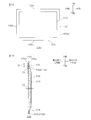
- FIG. 1A and 1B show an embodiment of the heat insulating material of the present invention.
- FIG. 1A shows a plan view and FIG. 1B shows a cross-sectional view.
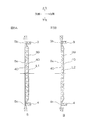
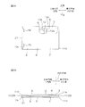
- 2A to 2C are manufacturing process diagrams of the heat insulating material shown in FIG. 1.
- FIG. 2A is a process of preparing a foam sheet and an air barrier layer
- FIG. 2B is a laminate of the foam sheet and the air barrier layer.
- FIG. 2C shows a step of thermally compressing the laminate.
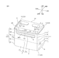
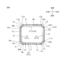
- FIG. 3 shows a perspective view of one embodiment of the battery cover of the present invention.
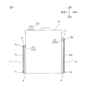
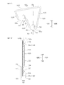
- FIG. 4 is a development view of the battery cover shown in FIG. 5A and 5B are cross-sectional views of FIG. 4,
- FIG. 5A shows a cross-sectional view along AA, and FIG.
- FIG. 5B shows a cross-sectional view along BB.
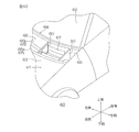
- FIG. 6 is a perspective view of the battery cover shown in FIG. 3 attached to the battery.
- FIG. 7 is a side sectional view taken along the line CC of FIG.
- FIG. 8 is a plan sectional view taken along the line DD of FIG.
- FIG. 9A and FIG. 9B are one form of the state which folded the battery cover shown in FIG. 3,
- FIG. 9A shows a side view
- FIG. 9B shows a top view.
- 10A and 10B are other forms in which the battery cover shown in FIG. 3 is folded
- FIG. 10A shows a side view
- FIG. 10B shows a plan view.
- 11A and 11B show an embodiment of the shielding member of the present invention.
- FIG. 11A shows a plan view
- FIG. 11B shows a cross-sectional view taken along line EE of FIG. 11A.
- FIG. 12 is a perspective view of a vehicle including the shielding member shown in
- the upper side of the paper is the upper side (one side in the first direction)
- the lower side of the paper is the lower side (the other side in the first direction)
- the left side of the paper is the left side (one side in the second direction)
- the right side of the paper is the right side ( The second side in the second direction)
- the front side of the paper is the one side in the thickness direction (one side in the third direction)
- the back side of the paper is the other side in the thickness direction (the other side in the third direction, the other side in the thickness direction).
- the directions in FIGS. 1B and 2A-2B also follow the direction in FIG. 1A.
- the heat insulating material 100 as the heat insulating material of the present invention includes a wall material 101, and preferably includes the wall material 101.
- the wall material 101 is formed in a substantially rectangular flat plate shape as shown in FIG. 1A, for example.
- the wall material 101 includes a high density portion 102 provided at a peripheral edge of the wall material 101 and a low density portion 103 provided inside the high density portion 102.
- the high density portion 102 is formed over the entire peripheral edge of the wall material 101. That is, the high density portion 102 is provided in a substantially rectangular frame shape so as to go around the peripheral edge of the wall material 101.
- the high-density portion 102 includes an upper-end high-density portion 102a that is formed continuously from the left end edge to the right-end edge at the upper end edge (one end edge) of the wall material 101, and the lower end edge ( The lower end high density portion 102b formed continuously from the left end edge to the right end edge at the other end edge) and the left end high density formed continuously from the upper end edge to the lower end edge at the left end edge of the wall material 101 102 c and a right end high density portion 102 d formed continuously from the upper end edge to the lower end edge at the right end edge of the wall material 101.
- the high-density portion 102 includes a compression portion 104, a first air barrier layer 105a provided on one surface of the compression portion 104 (a surface on one side in the thickness direction), and the other surface (thickness direction) of the compression portion 104. And a second air barrier layer 105b provided on the other surface. That is, in the high density portion 102, the compression portion 104 is sandwiched between the two air barrier layers 105 (105a and 105b) such that both surfaces of the compression portion 104 are in contact with the first air barrier layer 105a and the second air barrier layer 105b. Yes.
- the compression unit 104 includes a resin (not shown) impregnated in the compression unit 104.
- the thickness of the high density portion 102 is formed to be thinner than the thickness of the low density portion 103.
- the low-density portion 103 has heat insulation properties and is formed in a substantially rectangular shape at a substantially central portion other than the peripheral edge of the wall material 101. That is, the low density part 103 is provided in the middle from the upper end edge to the lower end edge of the wall material 101 and in the middle from the left end edge to the right end edge.
- the peripheral edge of the low density portion 103 is continuous with the inner peripheral edge of the high density portion 102 over the entire edge. That is, the low density portion 103 is provided so as not to be positioned at the peripheral edge of the wall material 101.
- the low density portion 103 has a thickness direction in which the other end in the thickness direction of the low density portion 103 coincides with the other end in the thickness direction of the high density portion 102 in the thickness direction.
- One end portion is provided so as to be positioned on one side in the thickness direction from one end portion in the thickness direction of the high density portion 102. That is, the low density portion 103 bulges toward the one side in the thickness direction with respect to the high density portion 102.
- the low density portion 103 includes a foam portion 106, a first air barrier layer 105a provided on one surface of the foam portion 106, and a second air barrier layer 105b provided on the other surface of the foam portion 106. I have. That is, in the low density part 103, the both faces of the foam part 106 are sandwiched between the two air barrier layers 105 (105a and 105b) so as to be in contact with the first air barrier layer 105a and the second air barrier layer 105b. .
- a foam sheet 110 as a foam and two air barrier layers 105 are prepared, and the foam sheet 110 is disposed between the two air barrier layers 105. To do.
- the foam sheet 110 has a foam formed into a sheet shape.
- the foam include polyurethane foam, polystyrene foam, polyolefin foam, chloroprene foam, and polyester foam.
- the foam By using the foam, the heat insulating property of the heat insulating material 100 is improved.
- polyurethane foams are preferable from the viewpoints of moldability and heat insulation.
- the open cell ratio of the foam sheet 110 is, for example, 50% or more, preferably 60% or more, and, for example, 100% or less.
- the thickness of the foam sheet 110 (before compression) is, for example, 1 mm or more, preferably 5 mm or more, and for example, 30 mm or less, preferably 20 mm or less.
- Examples of the air barrier layer 105 include a resin-impregnated nonwoven fabric.
- the resin-impregnated nonwoven fabric includes a nonwoven fabric and a resin impregnated in the nonwoven fabric.
- Nonwoven fabrics are, for example, natural fibers such as cotton, wool, hemp, pulp, silk, mineral fibers, for example, chemical fibers such as rayon, nylon fibers, polyester fibers, vinylon fibers, acrylic fibers, aramid fibers, polypropylene fibers, for example, It is formed from fibers such as glass fibers.
- polyester fibers and / or rayon are more preferable, and polyester fibers are more preferable.
- polyester fiber examples include polyethylene terephthalate (PET) fiber.
- the production method of the nonwoven fabric is not limited, and examples thereof include a dry method, a wet method, a spun bond method, a thermal bond method, a chemical bond method, a stitch bond method, a needle punch method, a melt blow method, a spun lace method, and a steam jet method. . From the viewpoint of moldability to the heat insulating material 100, a needle punch method is preferable.
- the basis weight of the nonwoven fabric is, for example, 5 g / m 2 or more, preferably 50 g / m 2 or more, for example, 1200 g / m 2 or less, preferably 500 g / m 2 or less, more preferably 200 g / m 2. m 2 or less.
- the resin may be either a thermosetting resin or a thermoplastic resin.
- thermosetting resin examples include a phenol resin and a resilcine resin (resonsinol resin).
- thermoplastic resin examples include polyester resin, acrylic resin, urethane resin, styrene butadiene rubber (SBS), polyvinyl chloride resin, and polyolefin resin.
- thermosetting resin is preferable from the viewpoint of moldability, and a resorcin resin is more preferable.
- the thickness of the air barrier layer 105 is, for example, 0.1 mm or more, preferably 0.2 mm or more, for example, 1.5 mm or less, preferably 1.0 mm or less. .
- the basis weight of the air barrier layer 105 is, for example, 10 g / m 2 or more, preferably 50 g / m 2 or more, and, for example, 1200 g / m 2 or less, preferably 500 g / m 2. m 2 or less, more preferably 200 g / m 2 or less.
- an air barrier layer 105 is laminated on both surfaces of the foam sheet 110 to obtain a laminate 111.
- an adhesive 112 is provided between the foam sheet 110 and the air barrier layer 105.
- the adhesive 112 between one surface of the foam sheet 110 and the other surface of the first air barrier layer 105a and between the other surface of the foam sheet 110 and one surface of the second air barrier layer 105b. Is placed (intervened).
- the adhesive 112 for example, a known adhesive is used.
- a hot melt adhesive that can be bonded by heating is used.
- a method for arranging the adhesive 112 for example, a method of applying a liquid adhesive partially to the foam sheet 110 or the air barrier layer 105 (specifically, only a portion corresponding to the low density portion 103 of the laminate 111). And a method of adhering the powdery adhesive so as to be scattered on the foam sheet 110 or the air barrier layer 105.
- a commercially available product in which an adhesive is previously attached to the surface of the air barrier layer 105 can also be used.
- the laminate 111 is thermally compressed.
- the high-density portion 102 (the upper-end high-density portion 102a, the lower-end high-density portion 102b, the left-end high-density portion 102c, the right-end high-density portion 102d) and the low-density portion 103 are formed in the stacked body 111.
- one surface and / or the other surface of the laminate 111 is compressed with a heating plate having a shape corresponding to the high-density portion 102 and the low-density portion 103.
- thermal compression is performed so that the pressure applied to the portion of the stacked body 111 where the high density portion 102 is formed becomes larger than the pressure applied to the portion of the stacked body 111 where the low density portion 103 is formed. More specifically, the portion corresponding to the high density portion 102 of the laminate 111 is thermally compressed with a high pressure that causes the elastic force of the foam sheet 110 to disappear, and corresponds to the low density portion 103 of the laminate 111. The portion is thermally compressed at a low pressure that does not cause the elastic force of the foam sheet 110 to disappear.
- the temperature of the heating plate is, for example, 120 ° C. or higher, preferably 140 ° C. or higher, and for example, 230 ° C. or lower, preferably 200 ° C. or lower.
- the foam sheet 110 is relatively strongly compressed in the portion of the laminated body 111 with respect to the high density portion 102, and the compressed portion 104 is formed.
- the foam sheet 110 is compressed relatively weakly, and the foam part 106 is formed.
- the resin of the resin-impregnated nonwoven fabric of the air barrier layer 105 flows by thermal compression and is impregnated in the compression portion 104.
- the wall material 101 in which the high density portion 102 (the upper end high density portion 102a, the lower end high density portion 102b, the left end high density portion 102c, the right end high density portion 102d) and the low density portion 103 are integrally formed is obtained.
- the compression part 104 of the high-density part 102 and the foaming part 106 of the low-density part 103 are continuously integrated, and the first air barrier layer 105a of the high-density part 102 and the first of the low-density part 103 are integrated.
- the air barrier layer 105a is continuously integrated, and the second air barrier layer 105b of the high density portion 102 and the second air barrier layer 105b of the low density portion 103 are continuously integrated.
- the thickness of the air barrier layer 105 after the thermal compression is the same as the thickness of the air barrier layer 105 before the thermal compression without any change.
- the high-density part 102 includes a compression part 104, a first air barrier layer 105 a provided on the upper surface of the compression part 104, and a second air barrier layer 105 b provided on the lower surface of the compression part 104.
- An adhesive 112 (see FIG. 2B) is provided between the compression unit 104 and the air barrier layer 105.
- the compression part 104 is formed from a compressed body in which the foam sheet 110 is highly compressed. Unlike the foam of the foam part 106 to be described later, the compression body is made of a hard body that does not include a large number of bubbles (cells) and has no elasticity.
- the compression unit 104 is impregnated with a resin impregnated nonwoven fabric. In this case, the compression unit 104 includes a compression body and a resin impregnated and solidified in the compression body.
- the compression rate in the compression unit 104 is, for example, 90% or more, preferably 92% or more, more preferably 95% or more, and for example, less than 100%, preferably 99% or less.
- the compression ratio of the compression unit 104 is expressed by the formula “ ⁇ (thickness of foam sheet before compression) ⁇ (thickness of compressed body after compression) ⁇ / (thickness of foam sheet before compression) ⁇ 100%”. It is calculated by.
- the thickness of the compression part 104 is 0.1 mm or more, for example, Preferably, it is 0.3 mm or more, for example, is 2.0 mm or less, Preferably, it is 1.0 mm or less.
- the density of the high density portion 102 exceed 0.45 g / cm 3, or preferably, 0.46 g / cm 3 or more, and is, for example, 2.0 g / cm 3 or less, preferably, 1.0 g / cm 3 or less.
- the thickness T1 of the high-density portion 102 is, for example, 0.1 mm or more, preferably 0.5 mm or more, and, for example, 3.0 mm or less, preferably 2.0 mm or less.
- the width W (the distance from the outer edge to the inner edge) of the high density portion 102 is, for example, 5.0 mm or more, preferably 10 mm or more, and, for example, 500 mm or less, preferably 50 mm or less. .
- the low density portion 103 includes a foam portion 106, a first air barrier layer 105a provided on one surface of the foam portion 106, and a second air barrier layer 105b provided on the other surface of the foam portion 106. Further, an adhesive 112 (see FIG. 2B) is provided between the foamed portion 106 and the air barrier layer 105.
- the foam sheet 110 is formed from a low-compression foam.
- the foam has a large number of bubbles (cells) inside, and the surface is recessed when stress is applied, and elastically restored to the original surface when the stress is released. Therefore, although the foaming part 106 is formed by compressing the foam sheet 110, unlike the compression body of the compression part 104, it is made of a foam having a large number of bubbles (cells) inside.
- the compression ratio of the foamed portion 106 is, for example, less than 90%, preferably 60% or less, more preferably 50% or less, still more preferably 30% or less, and for example, 0% or more, preferably Is 10% or more.
- the compression ratio of the foamed portion 106 is expressed by the formula “ ⁇ (thickness of the foam sheet before compression) ⁇ (thickness of the foamed portion after compression) ⁇ / (thickness of the foam sheet before compression) ⁇ 100%”. It is calculated by.
- the thickness of the foamed portion 106 is, for example, 1.5 mm or more, preferably 5.0 mm or more, more preferably 10 mm or more, and for example, 20 mm or less, preferably 15 mm or less.
- Density of the low density portion 103 is a 0.45 g / cm 3 or less, preferably, 0.20 g / cm 3 or less, more preferably, 0.10 g / cm 3 or less, more preferably, 0.06 g / cm 3 or less, for example, 0.01 g / cm 3 or more.
- the thickness T2 of the low density portion 103 is, for example, 2.0 mm or more, preferably 5.0 mm or more, more preferably 10 mm or more, and for example, 20 mm or less, preferably 15 mm or less.
- the ratio (T1 / T2) of the thickness T1 of the high density portion 102 to the thickness T2 of the low density portion 103 is, for example, 35% or less, preferably 15% or less, more preferably 10% or less. 1% or more, preferably 5% or more.
- the high density part 102 is provided over all the edges (an upper end edge, a lower end edge, a left end edge, and a right end edge) of a peripheral edge,
- the low density portion 103 is not disposed. Therefore, the mechanical strength at the peripheral edge can be improved, and the durability is excellent.
- the high density portion 102 is provided over the entire peripheral edge, and the high density portion 102 is formed thin. Therefore, water entry from the peripheral edge can be suppressed, so that water resistance can be improved. Therefore, corrosion of the heat insulating material 100 and reduction of heat insulating properties can be suppressed.
- the density of the low density part 103 is 0.45 g / cm ⁇ 3 > or less, it is excellent in heat insulation.
- the high density portion 102 includes a compression portion 104, a first air barrier layer 105 a provided on one surface of the compression portion 104, and a second air barrier layer provided on the other surface of the compression portion 104.
- the low density portion 103 includes a foam portion 106, a first air barrier layer 105 a provided on one surface of the foam portion 106, and a second air barrier layer 105 b provided on the other surface of the foam portion 106.
- the heat insulating property of the heat insulating material 100 can be further improved.
- the first air barrier layer 105a and the second air barrier layer 105b are resin-impregnated nonwoven fabrics comprising a nonwoven fabric and a resin impregnated into the nonwoven fabric.
- the water resistance, chemical resistance, and moldability of the heat insulating material 100 can be improved.
- the compression portion 104 is impregnated with a resin impregnated nonwoven fabric.
- the compression part 104, the 1st air barrier layer 105a, and the 2nd air barrier layer 105b can be closely_contact
- the mechanical strength and water resistance of the high density portion 102 can be further improved.
- the adhesive 112 is partially provided between the compression part 104 and the foaming part 106, and the 1st air barrier layer 105a. Moreover, the adhesive 112 is partially provided between the compression part 104 and the foaming part 106, and the 2nd air barrier layer 105b.
- the heat insulation of the heat insulating material 100 can be improved more reliably. .
- the compression part 104 is a compression body by which the foam sheet 110 was compressed
- the foaming part 106 is a foam
- the compression part 104 and the foaming part 106 can be formed from the one foam sheet 110, it is excellent in a moldability. Moreover, since the compression part 104 and the foaming part 106 are integrally formed, the mechanical strength of the wall material 101 is excellent.
- the high density portion 102 is formed over the entire edge of the peripheral edge of the wall material 101.
- 102 is formed over only one edge of the wall material 101 (at least one of the upper end high density portion 102a, the lower end high density portion 102b, the left end high density portion 102c, and the right end high density portion 102d, but not all of them). You can also
- the wall material 101 may include at least one of the upper end high density portion 102a, the lower end high density portion 102b, the left end high density portion 102c, and the right end high density portion 102d.
- at least one end edge of the upper end edge, the lower end edge, the left end edge, and the right end edge only needs to have the high density portion 102 formed over the entire edge.
- the high density portion 102 is formed only on the peripheral edge of the wall material 101.
- the high density portion 102 is formed on the wall material 101. It can also be formed inside.
- each one end edge is formed in a straight line shape.
- the one end edge is formed in a curved line shape. You can also.
- the foam sheet 110 is provided with the first air barrier layer 105a and the second air barrier layer 105b.
- the first air barrier layer 105a or the second air barrier layer 105b is provided on the foam sheet 110. Only one of the barrier layers 105b may be provided. Moreover, it is not necessary to provide both the first air barrier layer 105a and the second air barrier layer 105b.
- the adhesive 112 is partially provided between the foam sheet 110 and the air barrier layer 105, but the adhesive 112 includes the foam sheet 110 and the air barrier layer 105. It can also be provided on the entire surface between them. In that case, the resin of the resin-impregnated nonwoven fabric of the air barrier layer 105 is not impregnated in the compressed portion 104 and the foamed portion 106.
- this wall material 101 without providing the adhesive 112 between the foam sheet 110 and the air barrier layer 105 (105a, 105b), they can be thermally fused at the time of thermal compression.
- the heat insulating material 100 can be used for various industrial products such as a vehicle, an electric product, and a precision instrument that require heat insulating properties, and is particularly preferably used as a heat insulating material for an engine part of a vehicle. Specific examples include a battery cover and a shielding member.
- FIGS. 3 and 6 the directions described below are as indicated by the directional arrows shown in each figure.
- the directions in FIGS. 7 and 8 also conform to the directions shown in FIG.
- the direction in FIG. 4 is the upper side (first side in the first direction) on the paper surface
- the lower side on the paper surface is the lower side (the other side in the first direction)
- the left direction on the paper surface is one direction in the longitudinal direction of the battery cover
- the right direction on the paper is the other side in the longitudinal direction of the battery cover (the other side in the second direction)
- the front side on the paper is the inner side of the battery cover (the one side in the third direction).
- the rear side direction on the paper surface is the outer direction of the battery cover (the other side in the third direction).
- the directions in FIGS. 5, 9, and 10 also conform to the directions shown in FIG.
- the battery cover 1 has a rectangular tube shape extending in the vertical direction and is formed in a substantially rectangular frame shape in plan view.
- the battery cover 1 is formed from the heat insulating material 100 described above, and includes a plurality (four) of side walls 2 as wall materials, and a plurality of (four) connection portions 23 as wall materials connecting the side walls 2.
- the first spacer 3 as a spacer provided at the upper end of the inner surface of the side wall 2 and the connecting portion 23, and the second spacer 4 provided at the lower end of the inner surface of the side wall 2 and the connecting portion 23 (FIGS. 4 and 5A-B). For example).
- the four side walls 2 include a left wall 5 and a right wall 6 that are arranged to face each other in the left-right direction, and a front wall 7 and a rear wall 8 that are arranged to face each other in the front-rear direction. Yes.
- the four connecting portions 23 include a left front connecting portion 9 that connects the left wall 5 and the front wall 7, a left rear connecting portion 10 that connects the left wall 5 and the rear wall 8, and the right wall 6 and the front wall 7. And a right rear connecting portion 12 for connecting the right wall 6 and the rear wall 8 to each other.
- the side wall 2 and the connecting portion 23 are formed in a substantially rectangular shape that is long in the circumferential direction (longitudinal direction).
- a thin portion (described later) made of a high-density portion is formed at the upper end portion and the lower end portion of each of the side wall 2 and the connecting portion 23, and a thick portion (described later) made of a low-density portion having heat insulating properties is formed at the center portion. ) Is formed.
- a first spacer 3 is provided at the thin portion at the upper end, and a second spacer 4 is provided at the thin portion at the lower end.
- Each connecting portion 23 includes a connecting wall (described later) provided along the vertical direction and two bent portions (described later) provided on both sides of the connecting wall.
- each connecting portion 23 one of the side walls 2 adjacent to each other is connected to a connecting wall (described later) via one bent portion (described later), and the other side wall 2 is connected via the other bent portion. Connected to the connecting wall.
- the left wall 5 is formed in a substantially rectangular shape in a side view in which the vertical length is longer than the longitudinal length.
- the left wall 5 is integrally provided with a left thick part 5a made of a low density part, an upper left thin part 5b made of a high density part, and a lower left thin part 5c made of a high density part.
- the left thick portion 5a is formed in a substantially rectangular shape in a side view at a substantially vertical center of the left wall 5. As shown in FIG. 5A, the left thick part 5a bulges inward.
- the upper left thin portion 5b is adjacent to the upper side of the left thick portion 5a and is formed over the entire upper edge of the left wall 5, as shown by the broken line in FIG. 4 and FIG. 5A.
- the upper left thin part 5b is formed in a substantially rectangular shape in side view extending in the longitudinal direction.
- the vertical length of the upper left thin portion 5 b is substantially the same as the vertical length of the first spacer 3.
- the left lower thin portion 5c is formed over the entire lower edge of the left wall 5 adjacent to the lower side of the left thick portion 5a as shown by the broken line in FIG. 4 and FIG. 5A.
- the lower left thin portion 5c is formed in a substantially rectangular shape in side view extending in the longitudinal direction.
- the vertical length of the lower left thin portion 5 c is substantially the same as the vertical length of the second spacer 4.
- the thickness X1 (the distance from the inner surface to the outer surface) of the upper left thin portion 5b and the thickness Y1 (the distance from the inner surface to the outer surface) of the lower left thin portion 5c are each smaller than the thickness L1 of the left thick portion 5a. It is formed to become. Further, the thickness X1 of the upper left thin portion 5b is formed to be substantially the same as the thickness Y1 of the lower left thin portion 5c.
- the left wall 5 includes an engaged portion 13 at the other end portion in the longitudinal direction.
- the engaged portion 13 is provided to engage with an engaging portion 21 (described later) of the left rear connecting portion 10 to hold the battery cover 1 in a cylindrical shape.
- the engaged portion 13 has a substantially U shape that opens toward one side in the longitudinal direction, and is formed of a thin portion (high-density portion).
- the first engaged portion 14 and the first engaged portion The second engaged portion 15 disposed at a distance from the joint portion 14 and the overlapping portion 16 that connects the first engaged portion 14 and the second engaged portion 15 are integrally formed. In preparation.
- the first engaged portion 14 has a substantially rectangular shape in a side view, and a first slit 18 for inserting a first projecting portion 17 (described later) is formed along the vertical direction at the center in the vertical direction. .
- the second engaged portion 15 has a substantially rectangular shape in a side view, and a second slit 20 for inserting a second protrusion 19 (described later) is formed in the vertical direction center along the vertical direction. .
- the vertical length and the longitudinal length of the second engaged portion 15 and the first engaged portion 14 are substantially the same.
- the vertical lengths of the second slit 20 and the first slit 18 are substantially the same. That is, the shape of the second engaged portion 15 is substantially the same as the shape of the first engaged portion 14.
- the overlapping portion 16 has a substantially rectangular shape when viewed from the side, and the length in the longitudinal direction is formed to be shorter than the length in the longitudinal direction of the first engaged portion 14.
- a left front connecting portion 9 is formed integrally with the left wall 5 on one side in the longitudinal direction of the left wall 5.
- the left front connecting portion 9 is elongated in the vertical direction, and integrally includes a left front connecting wall 9A and a left front bent portion 9B disposed on both sides in the circumferential direction of the left front connecting wall 9A.
- the left front connecting wall 9A includes a left front thick part 9a made of a low density part, a left front upper thin part 9b made of a high density part, and a left front lower thin part 9c made of a high density part.
- the left front bent portion 9B includes a high density portion and includes two left front bent portions 9d and 9e.
- the left front thick portion 9a has a substantially rectangular shape in a side view along the vertical direction and is formed thick so as to bulge inward.
- the thickness L2 (the distance from the inner side surface to the outer side surface) of the left front thick part 9a is formed to be the same or smaller than the thickness of the left thick part 5a.
- the left front upper thin part 9b is formed adjacent to the upper side of the left front thick part 9a as referred to by the broken line in FIG. 4 and FIG. 5B.
- the left front upper thin part 9b is formed in a substantially rectangular shape in a side view.
- the vertical length of the upper left thin portion 9 b is substantially the same as the vertical length of the first spacer 3.
- the left front lower thin part 9c is formed adjacent to the lower side of the left front thick part 9a as referred to by the broken line in FIG. 4 and FIG. 5B.
- the left front lower thin portion 9c is formed in a substantially rectangular shape in side view.
- the vertical length of the left front lower thin portion 9 c is substantially the same as the vertical length of the second spacer 4.
- the thickness X2 of the left front upper thin part 9b and the thickness Y2 of the left front lower thin part 9c are each formed to be smaller than the thickness L2 of the left front thick part 9a. Further, the thickness X2 of the left front upper thin part 9b is formed to be substantially the same as the thickness Y2 of the left front lower thin part 9c. Further, the thickness X2 of the upper left thin portion 9b is formed to be substantially the same as the thickness X1 of the upper left thin portion 5b.
- the two left front bent portions 9d and 9e are formed adjacent to each other in one longitudinal direction and the other direction of the left front thick portion 9a, the left front upper thin portion 9b, and the left front lower thin portion 9c.
- the two left front bent portions 9d and 9e are formed in a linear shape extending in the vertical direction, and are formed from thin portions (high density portions).
- Each vertical length is the same length as the sum of the vertical lengths of the left front thick part 9a, the left front upper thin part 9b, and the left front lower thin part 9c.
- the left front thick part 9a is connected to the left wall 5 through one left front bent part 9d, and is connected to the front wall 7 through the other left front bent part 9e.
- a front wall 7 is formed integrally with the left front connecting portion 9 on one side in the longitudinal direction of the left front connecting portion 9.
- the front wall 7 has a substantially rectangular shape in a side view having a length in the longitudinal direction longer than that of the left wall 5, and an upper end portion of the front wall 7 is notched in a substantially U shape in a side view.
- the front wall 7 is integrally provided with a front thick part 7a made of a low density part, a front upper thin part 7b made of a high density part, and a front lower thin part 7c made of a high density part.
- the front thick part 7a is formed in a substantially rectangular shape in a side view at a substantially vertical center of the front wall 7.
- the front thick part 7a bulges inward.
- the thickness (the distance from the inner side surface to the outer side surface) of the front thick part 7a is substantially the same as the thickness of the left thick part 5a.
- the front upper thin part 7 b is adjacent to the upper side of the front thick part 7 a and is formed over the entire upper edge of the front wall 7.
- the front upper thin portion 7 b is formed in a substantially U shape whose upper end edge is along the upper end portion of the front wall 7.
- the thickness of the front upper thin part 7b is substantially the same as the thickness of the upper left thin part 5b.
- the front lower thin part 7c is adjacent to the lower side of the front thick part 7a and is formed over the entire lower edge of the front wall 7 as shown by the broken line in FIG.
- the front lower thin portion 7c is formed in a substantially rectangular shape in side view extending in the longitudinal direction.
- the vertical length of the front lower thin portion 7 c is substantially the same as the vertical length of the second spacer 4.
- the thickness of the front lower thin portion 7c is substantially the same as the thickness of the left lower thin portion 5c.
- a right front connecting portion 11 is formed integrally with the front wall 7 on one side in the longitudinal direction of the front wall 7.
- the right front connecting part 11 is substantially the same shape as the left front connecting part 9 and is elongated in the vertical direction, and integrally includes a right front connecting wall 11A and right front bent parts 11B disposed on both sides in the circumferential direction of the right front connecting wall 11A. ing.
- the right front connecting wall 11A includes a right front thick part 11a made of a low density part, a right front upper thin part 11b made of a high density part, and a right front lower thin part 11c made of a high density part.
- the right front bent portion 11B includes two right front bent portions 11d and 11e.
- the front right thick portion 11a has a substantially rectangular shape in a side view along the vertical direction, and is formed thick so as to bulge inward.
- the thickness of the right front thick part 11a is substantially the same as the thickness of the left front thick part 9a.
- the front right upper thin part 11b is formed adjacent to the upper side of the right front thick part 11a as shown by the broken line in FIG.
- the front right upper thin part 11b is formed in a substantially rectangular shape in a side view.
- the vertical length of the upper right thin portion 11 b is substantially the same as the vertical length of the first spacer 3.
- the thickness of the upper right thin portion 11b is formed to be substantially the same as the thickness of the upper left thin portion 5b.
- the right front lower thin part 11c is formed adjacent to the lower side of the right front thick part 11a as shown by the broken line in FIG.
- the right front lower thin part 11c is formed in a substantially rectangular shape in a side view.
- the vertical length of the right front lower thin portion 11 c is substantially the same as the vertical length of the second spacer 4.
- the thickness of the lower right thin portion 11c is formed to be substantially the same as the thickness of the lower left thin portion 5c.
- the two right front bent portions 11d and 11e are formed adjacent to each other in one longitudinal direction and the other direction of the right front thick portion 11a, the right front upper thin portion 11b, and the right front lower thin portion 11c.
- the two right front bent portions 11d and 11e are formed in a linear shape extending in the vertical direction, and are formed from thin portions (high density portions). Each vertical length is the same as the sum of the vertical lengths of the right front thick part 11a, the right front upper thin part 11b, and the right front lower thin part 11c.
- the right front thick part 11a is connected to the front wall 7 through one right front bent part 11d and is connected to the right wall 6 through the other right front bent part 11e.
- the right wall 6 is formed integrally with the right front connecting part 11 on one side in the longitudinal direction of the right front connecting part 11.
- the right wall 6 is shorter than the front wall 7 and has a substantially rectangular shape in a side view having substantially the same length in the longitudinal direction as the left wall 5, and is composed of a right thick portion 6 a composed of a low density portion and a high density portion.
- the upper right thin portion 6b and the lower right thin portion 6c made of a high density portion are integrally provided.
- the right thick portion 6a is formed in a substantially rectangular shape in a side view at the approximate center of the right wall 6 in the vertical direction.
- the right thick part 6a bulges inward.
- the thickness of the right thick part 6a is formed substantially the same as the thickness of the left thick part 5a.
- the upper right thin portion 6b is formed over the entire upper edge of the right wall 6 adjacent to the upper side of the right thick portion 6a, as shown by the broken line in FIG.
- the upper right thin portion 6b is formed in a substantially rectangular shape in side view extending in the longitudinal direction.
- the vertical length of the upper right thin portion 6 b is substantially the same as the vertical length of the first spacer 3.
- the thickness of the upper right thin portion 6b is substantially the same as the thickness of the upper left thin portion 5b.
- the lower right thin part 6c is adjacent to the lower side of the right thick part 6a and is formed over the entire lower edge of the right wall 6, as shown by the broken line in FIG.
- the lower right thin portion 6c is formed in a substantially rectangular shape in side view extending in the longitudinal direction.
- the vertical length of the lower right thin portion 6 c is substantially the same as the vertical length of the second spacer 4.
- the thickness of the lower right thin portion 6c is substantially the same as the thickness of the lower left thin portion 5c.
- the right rear connecting portion 12 is formed integrally with the right wall 6 on one side in the longitudinal direction of the right wall 6.
- the right rear connecting portion 12 is substantially the same shape as the left front connecting portion 9 and is elongated in the vertical direction.
- the right rear connecting wall 12A and the right rear bent portion 12B disposed on both sides in the circumferential direction of the right rear connecting wall 12A are provided.
- the right rear connecting wall 12A includes a right rear thick part 12a made of a low density part, a right rear upper thin part 12b made of a high density part, and a right rear lower thin part 12c made of a high density part.
- the right rear bent portion 12B includes two right rear bent portions 12d and 12e.
- the right rear thick portion 12a has a substantially rectangular shape in a side view along the vertical direction, and is formed thick so as to bulge inward.
- the thickness of the right rear thick part 12a is substantially the same as the thickness of the left front thick part 9a.
- the right rear upper thin part 12b is formed adjacent to the upper side of the right rear thick part 12a as shown by the broken line in FIG.
- the right rear upper thin part 12b is formed in a substantially rectangular shape in a side view.
- the vertical length of the right rear upper thin portion 12 b is substantially the same as the vertical length of the first spacer 3.
- the thickness of the right rear upper thin part 12b is formed to be substantially the same as the thickness of the upper left thin part 5b.
- the right rear lower thin portion 12c is formed adjacent to the lower side of the right rear thick portion 12a as shown by the broken line in FIG.
- the right rear lower thin portion 12c is formed in a substantially rectangular shape in a side view.
- the vertical length of the right rear lower thin portion 12 c is substantially the same as the vertical length of the second spacer 4.
- the thickness of the lower right lower thin portion 12c is formed to be substantially the same as the thickness of the lower left thin portion 5c.
- the two right rear bent portions 12d and 12e are formed adjacent to each other in one longitudinal direction and the other direction of the right rear thick portion 12a, the right front upper thin portion 11b, and the right front lower thin portion 11c.
- the two right rear bent portions 12d and 12e are formed in a linear shape extending in the vertical direction, and are formed from thin portions (high-density portions). Each vertical length is the same as the sum of the vertical lengths of the right rear thick portion 12a, the right rear upper thin portion 12b, and the right rear lower thin portion 12c.
- the right rear thick part 12a is connected to the right wall 6 through one right rear bent part 12d and is connected to the rear wall 8 through the other right rear bent part 12e.
- the rear wall 8 is formed integrally with the right rear connecting portion 12 on one side in the longitudinal direction of the right rear connecting portion 12.
- the rear wall 8 is longer than the right wall 6 and has a substantially rectangular shape in a side view having substantially the same longitudinal length as the front wall 7, and its upper end is shallower than the upper end of the front wall 7. It is cut out in a substantially U shape when viewed from the side.
- the rear wall 8 is integrally provided with a rear thick portion 8a composed of a low density portion, a rear upper thin portion 8b composed of a high density portion, and a rear lower thin portion 8c composed of a high density portion.
- the rear thick portion 8a is formed in a substantially rectangular shape in a side view at the approximate center of the rear wall 8 in the vertical direction.
- the rear thick part 8a bulges inward.
- the thickness of the rear thick part 8a is substantially the same as the thickness of the left thick part 5a.
- the rear upper thin portion 8b is adjacent to the upper side of the rear thick portion 8a and is formed over the entire upper edge of the rear wall 8.
- the rear upper thin portion 8 b has an upper end edge formed in a substantially U shape along the upper end portion of the rear wall 8.
- the thickness of the rear upper thin part 8b is substantially the same as the thickness of the upper left thin part 5b.
- the rear lower thin portion 8 c is adjacent to the lower side of the rear thick portion 8 a and is formed over the entire lower edge of the rear wall 8.
- the rear lower thin portion 8c is formed in a substantially rectangular shape in side view extending in the longitudinal direction.
- the vertical length of the rear lower thin portion 8 c is substantially the same as the vertical length of the second spacer 4.
- the thickness of the rear lower thin portion 8c is substantially the same as the thickness of the left lower thin portion 5c.
- the left rear connecting portion 10 is formed integrally with the rear wall 8 on one side in the longitudinal direction of the rear wall 8.
- the left rear connecting portion 10 is substantially the same shape as the left front connecting portion 9 and is elongated in the vertical direction, and includes a left rear connecting wall 10A and left rear bent portions 10B disposed on both sides in the circumferential direction of the left rear connecting wall 10A. Integrated.
- the left rear connecting wall 10A includes a left rear thick portion 10a made of a low density portion, a left rear upper thin portion 10b made of a high density portion, and a left rear lower thin portion 10c made of a high density portion.
- the left rear bent portion 10B includes two left rear bent portions 10d and 10e.
- the left rear thick portion 10a has a substantially rectangular shape in a side view along the vertical direction and is formed thick so as to bulge inward.
- the thickness of the left rear thick part 10a is substantially the same as the thickness of the left front thick part 9a.
- the left rear upper thin part 10b is formed adjacent to the upper side of the left rear thick part 10a as shown by a broken line in FIG.
- the left rear upper thin part 10b is formed in a substantially rectangular shape in a side view.
- the vertical length of the left rear upper thin portion 10 b is substantially the same as the vertical length of the first spacer 3.
- the thickness of the upper left thin portion 10b is formed to be substantially the same as the thickness of the upper left thin portion 5b.
- the left rear lower thin portion 10c is formed adjacent to the lower side of the left rear thick portion 10a as shown by the broken line in FIG.
- the left rear lower thin portion 10c is formed in a substantially rectangular shape in side view.
- the vertical length of the left rear lower thin portion 10 c is substantially the same as the vertical length of the second spacer 4.
- the thickness of the left rear lower thin portion 10c is formed to be substantially the same as the thickness of the left lower thin portion 5c.
- the two left rear bent portions 10d and 10e are formed adjacent to each other in one longitudinal direction and the other direction of the left rear thick portion 10a, the left rear upper thin portion 10b, and the left rear lower thin portion 10c. .
- the two left rear bent portions 10d and 10e are formed in a linear shape extending in the vertical direction, and are formed from thin portions (high-density portions). Each vertical length is the same as the sum of the vertical lengths of the left rear thick portion 10a, the left rear upper thin portion 10b, and the left rear lower thin portion 10c.
- the left rear thick portion 10a is connected to the rear wall 8 through one left rear bent portion 10d, and is connected to an engaging portion 21 (described later) through the other left rear bent portion 10e.
- the left rear connecting portion 10 includes an engaging portion 21 formed of a high-density portion at one end portion in the longitudinal direction.
- the engaging portion 21 is formed of a thin portion (high density portion), and includes a first protruding portion 17 and a second protruding portion 19 on one side in the longitudinal direction.
- the first projecting portion 17 projects in one longitudinal direction above the engaging portion 21 and is formed from a first projecting portion 24 formed in a substantially rectangular shape in a side view and from one end in the longitudinal direction of the first projecting portion 24 or A head 25 that bulges downward is integrally provided.
- the vertical length of the first protrusion 24 is formed to be substantially the same as the vertical length of the first slit 18.
- the second projecting portion 19 is provided to be spaced downward from the first projecting portion 17 and is formed so as to project in one longitudinal direction of the engaging portion 21.
- the second protrusion 19 is formed in substantially the same shape as the first protrusion 17. That is, the second projecting portion 19 projects in one longitudinal direction below the engaging portion 21 and is formed from a second projecting portion 26 formed in a substantially rectangular shape in side view and one end portion in the longitudinal direction of the second projecting portion 26.
- a second head 27 bulging upward or downward is integrally provided.
- the vertical length of the second protrusion 26 is formed to be substantially the same as the vertical length of the second slit 20.
- Each of the four connecting portions 23 (the left front connecting portion 9, the left rear connecting portion 10, the right front connecting portion 11, and the right rear connecting portion 12) constitutes a folding portion 28, so that the inner surface of the side wall 2 is in contact with the battery.
- the cover 1 can be folded.
- a first spacer 3 is provided at the upper edge of each side wall 2 of the battery cover 1 and the inner side surface of each connecting portion 23. More specifically, the first spacer 3 includes the upper left thin portion 5b, the left front upper thin portion 9b, the front upper thin portion 7b, the right front upper thin portion 11b, the upper right thin portion 6b, the right rear upper thin portion 12b, and the rear upper thin portion. It is provided continuously along the upper edge of the inner surface of the portion 8b and the left rear upper thin portion 10b.
- the first spacers 3 are disposed on the side walls 2 and the connection portions 23 so that the upper end portions of the side walls 2 and the connection portions 23 and the upper end portions of the first spacers 3 are flush with each other.
- the inner side surface of the first spacer 3 is located on the inner side of the inner side surfaces of the thick portions (the left thick portion 5a, the right thick portion 6a, the front thick portion 7a, and the rear thick portion 8a) of each side wall 2. And it is located inside the inner wall of the connection wall (the left front thick part 9a, the left rear thick part 10a, the right front thick part 11a, and the right rear thick part 12a) of each connection part 23.
- the first spacer 3 is formed in a substantially rectangular shape in sectional view extending in the longitudinal direction, and is formed from a foam (sponge).
- a second spacer 4 is provided at the lower end edge of each side wall 2 of the battery cover 1 and the inner side surface of each connecting portion 23. More specifically, the second spacer 4 includes a left lower thin portion 5c, a left front lower thin portion 9c, a front lower thin portion 7c, a right front lower thin portion 11c, a right lower thin portion 6c, a right rear lower thin portion 12c, and a rear lower portion. It is provided continuously along the lower end edge of the inner side surface of the thin portion 8c and the left rear lower thin portion 10c.
- the second spacer 4 is disposed on each side wall 2 and each connecting portion 23 so that the lower end surfaces of each side wall 2 and each connecting portion 23 and the lower end surface of the second spacer 4 are flush with each other.
- the inner surface of the second spacer 4 is located on the inner side of the inner surfaces of the thick portions (left thick portion 5a, right thick portion 6a, front thick portion 7a, and rear thick portion 8a) of each side wall 2. And it is located inside the inner wall of the connection wall (the left front thick part 9a, the left rear thick part 10a, the right front thick part 11a, and the right rear thick part 12a) of each connection part 23.
- the second spacer 4 is formed in a substantially rectangular shape in sectional view extending in the longitudinal direction.
- the second spacer 4 is formed of the same material as the first spacer 3, that is, a foam (sponge).
- a thin portion consisting of a high density portion is formed over the entire circumference.
- the upper thin part 10b is continuously formed over the entire edge of each side wall 2 and the upper end edge of each connecting part 23. Moreover, all the thin parts formed in an upper end edge are formed in substantially the same thickness.
- the lower end edge of the battery cover 1 is formed with a thin portion consisting of a high-density portion over the entire circumference.
- the rear lower thin portion 10 c is formed continuously over the entire edge of the lower end edge of each side wall 2 and each connecting portion 23.
- all the thin parts formed in a lower end edge are formed in substantially the same thickness.
- a foam sheet 110 and two air barrier layers 105 are prepared, and the foam sheet 110 is disposed between the two air barrier layers 105.
- the air barrier layer 105 is laminated on both surfaces of the foam sheet 110 to obtain a laminate 111.
- an adhesive 112 is provided between the foam sheet 110 and the air barrier layer 105 as necessary.
- a predetermined portion of the laminated body 111 is thermally compressed to form a thick portion and a thin portion.
- the laminated body 111 is divided into each thick part (left thick part 5a, right thick part 6a, front thick part 7a and rear thick part 8a, left front thick part 9a, left rear thick part.
- thermal compression is performed so that the pressure on the thin portion is larger than the pressure on the thick portion. More specifically, the portion corresponding to the thin-walled portion is thermally compressed at a pressure high enough to eliminate the elastic force of the foam sheet 110, and the portion corresponding to the thick-walled portion disappears the elasticity of the foam sheet 110. It is hot-compressed at a low pressure that does not allow
- a thin part composed of a high density part and a thick part composed of a low density part can be integrally formed.
- the thickness L1 of the left thick portion 5a is, for example, 2.0 mm or more, preferably 5.0 mm or more, more preferably 10 mm or more, and for example, 20 mm or less, preferably 15 mm or less. Moreover, the thickness of the front thick part 7a, the right thick part 6a, and the rear thick part 8a is also the same as the said range.
- the thickness L2 of the left front thick portion 9a is, for example, 1.0 mm or more, preferably 2.0 mm or more, and for example, 15 mm or less, preferably 10 mm or less.
- the thicknesses of the right front thick part 11a, the right rear thick part 12a, and the left rear thick part 10a are also the same as the above range.
- each thin part that is, X1, X2, Y1, and Y2 are all substantially the same, for example, 0.1 mm or more, preferably 0.5 mm or more, and, for example, 3.0 mm or less, Preferably, it is 2.0 mm or less.
- the length (distance from the outer edge to the inner edge) is, for example, 5.0 mm or more, preferably 10 mm or more, and, for example, 500 mm or less, preferably 50 mm or less.
- each bent portion is, for example, It is 2 mm or more, preferably 6 mm or more, and for example, 35 mm or less, preferably 20 mm or less.
- the outer shape is processed. More specifically, the laminated body 111 is cut along the outer shape of the development view (FIG. 4) of the battery cover 1.
- the left wall 5, the left front connecting part 9, the front wall 7, the right front connecting part 11, the right wall 6, the right rear connecting part 12, the rear wall 8, and the left rear connecting part 10 are successively arranged in this order.
- An integrally formed battery cover wall material is obtained.
- a long first spacer 3 having a substantially rectangular shape in side view is attached along the upper edge of the inner side surface of the battery cover wall material.
- the first spacer 3 is formed from a foam.
- the foam used for the first spacer 3 include ethylene / propylene / diene rubber foam (EPDM foam), ethylene / propylene foam (EPM foam), polyurethane foam, polystyrene foam, polyolefin foam, Examples include chloroprene foam.
- EPDM foam is used.
- the thickness (the distance from the innermost side to the outermost side) of the first spacer 3 is, for example, 1 mm or more, preferably 5 mm or more, more preferably 10 mm or more, and for example, 30 mm or less, preferably 15 mm. It is as follows.
- the vertical length of the first spacer 3 is, for example, 3 mm or more, preferably 7 mm or more, and for example, 15 mm or less, preferably 10 mm or less.
- a long second spacer 4 having a substantially rectangular shape in side view is attached along the lower edge of the inner side surface of the battery cover wall material.
- the second spacer 4 is formed from a foam.
- a foam the same thing as the 1st spacer 3 is mentioned, for example.
- EPDM foam is used.
- the thickness and the vertical length of the second spacer 4 are substantially the same as the thickness and the vertical length of the first spacer 3, respectively.
- the front wall 7 and the rear wall 8 face each other with a space in the front-rear direction
- the left wall 5 and the right wall 6 face each other with a space in the left-right direction. It is formed in a substantially rectangular shape in plan view that is long in the left-right direction.
- the side walls 2 front wall 7 and left wall 5, left wall 5 and rear wall 8, rear wall 8 and right wall 6, right wall 6, which are arranged adjacent to each other at substantially right angles. And the front wall 7) are connected via respective connecting portions 23 (left front connecting portion 9, left rear connecting portion 10, right front connecting portion 11, right rear connecting portion 12).
- each connecting portion 23 two bent portions (left front bent portions 9d and 9e, left) sandwiching a connecting wall (left front thick portion 9a, left rear thick portion 10a, right front thick portion 11a, right rear thick portion 12a)
- the rear bent portions 10d and 10e, the right front bent portions 11d and 11e, and the right rear bent portions 12d and 12e) are bent to realize a substantially right-angled arrangement of the side walls 2 adjacent to each other.
- one of the side walls 2 adjacent to each other (for example, the front wall 7) and the connecting portion 23 (for example, the left front connecting portion 9) are bent at one bent portion (for example, the left front bent portion 9e). Accordingly, an obtuse angle (for example, 100 to 175 degrees, preferably 120 to 150 degrees, most preferably 135 degrees) is formed inside the rectangular tube shape, and the side walls 2 adjacent to each other are connected.
- the other side wall 2 (for example, the left wall 5) and the connecting portion 23 (for example, the left front connecting portion 9) are bent at the other bent portion (for example, the bent portion 9d), so that the inside of the rectangular tube shape is formed. It connects so that an obtuse angle may be formed.
- each of the four corners of the battery cover 1 is formed in a substantially trapezoidal shape in plan view by forming two corners (obtuse angles) by the side walls 2 and the connecting portions 23 arranged adjacent to each other at substantially right angles. Is done.
- the battery 31 is a secondary battery (preferably a secondary battery mounted on a vehicle) mounted on a vehicle, a ship, etc., and is filled with a battery liquid 32. Yes.
- the battery 31 is formed in a substantially rectangular parallelepiped shape. Two terminals 33 are provided on the upper surface, and a battery liquid detection unit 35 that allows the battery liquid interface 34 to be visually observed from the outside is provided on the front surface. Yes.
- the battery liquid detection unit 35 is provided with an upper limit scale 36a indicating the upper limit of the filling amount of the battery liquid 32 and a lower limit scale 36b indicating the lower limit of the filling amount of the battery liquid 32.
- the battery liquid 32 is filled in the battery 31 so that the battery liquid interface 34 is located between the upper limit scale and the lower limit scale.
- the battery cover 1 is attached to the battery 31 such that the side surface (front surface) of the battery 31 where the battery liquid detection unit 35 is located is opposed to the front wall 7 of the battery cover 1. At this time, the battery fluid detection unit 35 is exposed from the upper end portion of the front wall 7 cut out in a substantially U shape.
- the battery cover 1 is formed so that the space defined from the four side walls 2 (inner side surfaces) of the battery cover 1 is slightly larger than the side surface of the battery 31. Yes.
- the outer peripheral shape of the battery cover 1 is formed into a shape in which the corners of the four corners are chamfered obliquely, that is, a substantially octagonal shape in plan view.
- four connecting walls comprising four corners (particularly, a left front thick part 9a, a left rear thick part 10a, a right front thick part 11a, and a right rear thick part 12a). ) Protrudes inward. Therefore, when the battery 31 is mounted on the battery cover 1, the four connecting walls come into contact with the four corners 38 (corners: 38 a, 38 b, 38 c, 38 d) on the side surface of the battery, and the battery cover 1 31 is fixed.
- first spacer 3 contacts the upper part of the side surface of the battery 31, and the second spacer 4 contacts the lower part of the side surface of the battery 31.
- the inner side surface of the first spacer 3 is in contact with the side surface of the battery 31 in the entire circumferential direction
- the inner side surface of the second spacer 4 is in contact with the side surface of the battery 31 in the entire circumferential direction.
- the bottom surface of the battery 31 is flush with the lower end surface of the second spacer 4 and the lower end surface of the side wall 2 of the battery cover 1.
- a front space 37 a is defined from the first spacer 3, the left front thick part 9 a, the right front thick part 11 a, the second spacer 4, the front wall 7, and the front surface of the battery 31.
- a rear space 37b is defined from the first spacer 3, the left rear thick portion 10a, the right rear thick portion 12a, the second spacer 4, the rear wall 8, and the rear side surface of the battery.
- a left space 37c is defined from the first spacer 3, the left front thick part 9a, the left rear thick part 10a, the second spacer 4, the left wall 5, and the left side surface of the battery 31.
- a right space 37d is defined from the first spacer 3, the right front thick portion 11a, the right rear thick portion 12a, the second spacer 4, the right wall 6, and the right side surface of the battery.
- each space 37 is, for example, 1 mm or more, preferably 3 mm or more, and for example, 15 mm or less, preferably 10 mm or less.
- the battery cover 1 can be folded as shown in FIGS. 9A-B or 10A-B.
- FIGS. 9A to 9B the right front bent portions 11d and 11e of the right front connecting portion 11 and the left rear bent portions 10d and 10e of the left rear connecting portion 10 are bent and the left front bent portion of the left front connecting portion 9 is bent.
- the portions 9d and 9e and the right rear bent portions 12d and 12e of the right rear connecting portion 12 are continuously flattened, and the rear wall 8,
- the right rear connecting portion 12 and the right wall 6 are continuously formed into a flat plate shape and are folded so as to overlap each other.
- the first spacer 3 and the second spacer 4 extend along the two right front bent parts 11d and 11e. And bent into a substantially U shape in plan view.
- FIGS. 10A-10B the left front bent portions 9d and 9e of the left front connecting portion 9 and the right rear bent portions 12d and 12e of the right rear connecting portion 12 are bent, and the right front bent portion 11d of the right front connecting portion 11 and 11e and the left rear bent portions 10d and 10e of the left rear connecting portion 10 are extended so that the front wall 7, the right front connecting portion 11 and the right wall 6 are continuously flattened, and the rear wall 8 and the left rear connecting portion are connected.
- the part 10 and the left wall 5 are continuously flat and are folded so that they overlap.
- the first spacer 3 and the second spacer 4 are along the two left front bent portions 9d and 9e. And bent into a substantially U shape in plan view.
- the battery cover 1 has a side wall 2 (left wall 5, right wall 6, front wall 7, and rear wall 8) that covers the four side surfaces of the battery 31 and a connecting portion 23 that connects the side walls 2.
- the upper end edge and the lower end edge of (the left front connection part 9, the left rear connection part 10, the right front connection part 11 and the right rear connection part 12) are composed of thin portions composed of high density parts, and the upper end edge and the lower end edge thereof are The thick part which consists of a low density part is not arrange
- the upper end edge and the lower end edge are formed of a thin portion consisting of a high density portion, and the thickness of the thin portion is formed thinner than the thickness of the thick portion. Therefore, since water can be prevented from entering the battery cover 1 from the upper edge and the lower edge, the water resistance can be improved. Therefore, corrosion of the battery cover 1 and reduction of heat insulation can be suppressed.
- the density of a thin part is 0.45 g / cm ⁇ 3 > or less, it is excellent in heat insulation.
- the side wall 2 (the left wall 5, the right wall 6, the front wall 7, and the rear wall 8) that covers the four side surfaces of the battery 31 and the first spacer 3 provided on the upper side of the side wall 2.
- the second spacer 4 provided at the lower part of the side wall 2, a space 37 (air layer) is generated between the side surface of the battery 31 and each side wall 2 of the battery cover 1.
- the battery cover 1 is excellent in heat insulation, and can effectively protect the battery 31 from external heat.
- connecting walls (the left front thick part 9a, the left rear thick part 10a, the right front thick part 11a and the right rear thick part 12a) are provided on the side wall 2 along the vertical direction. It contacts the side surface of the battery 31 along the vertical direction.
- the space 37 between the side wall 2 of the battery cover 1 and the side surface of the battery 31 can be held.
- the connecting wall contacts the corners 38 (38 a, 38 b, 38 c and 38 d) on the side surface of the battery. 2 is provided.
- the corner 38 on the side surface of the battery 31 has high strength, so that the battery cover 1 can be attached to the battery 31 more reliably.
- four connecting walls (a left front thick part 9a, a left rear thick part 10a, a right front thick part 11a, and a right rear thick part 12a) are provided at each of the four corners 38 on the side surface of the battery 31. It is provided in the side wall 2 so that it may contact.
- the connecting wall contacts the four corners 38a, 38b, 38c and 38d of the battery 31, the battery cover 1 can be more securely attached to the battery 31, and the side wall 2 of the battery cover 1 and the side surface of the battery 31 can be secured.
- the space 37 between the two can be held.
- the battery cover 1 includes each side wall 2 (left wall 5, right wall 6, front wall 7 and rear wall 8) and each connecting portion 23 (left front connecting portion 9, left rear connecting portion 10, right front connecting portion 11 and The right rear connecting portion 12) forms a substantially octagonal shape in plan view. Therefore, a space can be reliably formed between the side wall 2 of the battery cover 1 and the side surface of the battery 31.
- the space 37 can be formed and stored between the battery cover 1 and the battery 31 more reliably.
- the battery cover 1 is provided with four folding portions 28 (the left front connecting portion 9, the left rear connecting portion 10, the right front connecting portion 11 and the right rear connecting portion 12) spaced apart from each other. Therefore, since the battery cover 1 can be folded so that the inner surface of the side wall 2 contacts, it can be carried compactly and stored.
- each of the folding portions 28 includes two bent portions (left front bent portions 9d and 9e, left rear bent portions 10d and 10e, right front bent portions 11d and 11e, and right rear bent portion 12d. And 12e).
- the battery cover 1 can be formed in a substantially octagonal shape in plan view as described above, and a space can be reliably formed between the side wall 2 of the battery cover 1 and the side surface of the battery 31.
- the side walls 2 facing each other at the folding portion 28 can be kept at a predetermined distance, so that the stress generated by the contact between the first spacers 3 provided on the inner surface of the side wall 2. Can be relaxed. As a result, when the battery cover 1 is folded and stored, damage to the first spacer 3 can be reduced.
- the side wall 2 is formed from a low density portion and includes the foamed portion 106, so that the heat insulating property of the battery cover 1 is further improved. Therefore, the battery 31 can be reliably protected from heat.
- the side wall 2 includes the foam portion 106 and the two air barrier layers 105 (105a and 105b) laminated on both surfaces of the foam portion 106, the heat insulating property of the battery cover 1 is further improved. Further improvement. Therefore, the battery 31 can be reliably protected from heat.
- the upper side of the page is the upper side (one side in the first direction)
- the lower side of the page is the lower side (the other side in the first direction)
- the left side of the page is the front side (one side in the second direction)
- the right side of the page is the rear side (The other side in the second direction)
- the front side of the paper is the left side (third side in the third direction)
- the back side of the paper surface is the right side (the other side in the third direction).
- the directions in FIGS. 11B and 12 also follow the direction in FIG. 11A.
- the shielding member 50 includes a shielding plate 51 and a clip 53 attached to the shielding plate 51.
- the shielding plate 51 is formed in a substantially flat plate shape.
- the shielding plate 51 is formed in a predetermined shape corresponding to a cross-sectional shape of a space of a structural member described later, and is formed in, for example, a substantially L shape.
- the shielding plate 51 is formed from the wall material 101 of the heat insulating material 100 described above, and the high density portion 102 provided at the peripheral edge of the shielding plate 51 and the low density portion provided inside the high density portion 102. 103.
- the high density portion 102 is continuously connected from the lower end of the upper end high density portion 52a, the rear end high density portion 52b extending from the rear end of the upper end high density portion 52a to the lower side, and the lower end of the rear end high density portion 52b from the lower end to the front side.
- the first lower end high density part 52c extending, the first front end high density part 52d extending upward from the front end of the first lower end high density part 52c, and the second rear extending from the upper end of the first front end high density part 52d toward the front side.
- An end high density portion 52e and a second front end high density portion 52f extending upward from the front end of the second rear end high density portion 52e are provided.
- the upper end high density portion 52 a is provided over the entire edge of the upper end of the shielding plate 51. That is, it is provided continuously from the upper end of the rear end high density portion 52b to the upper end of the second front end high density portion 52f.
- the rear end high density portion 52b is provided over the entire rear edge of the shielding plate 51. That is, it is provided continuously from the rear end of the upper end high density portion 52a to the rear end of the first lower end high density portion 52c.
- the first lower-end high-density portion 52c is provided over the entire rear edge at the rear portion of the shielding plate 51. That is, it is provided continuously from the lower end of the rear end high density portion 52b to the lower end of the first front end high density portion 52d.
- the first front end high-density portion 52d is provided over the entire front edge of the rear and lower portions of the shielding plate 51. That is, it is provided continuously from the front end of the first lower end high density portion 52c to the rear end of the second rear end high density portion 52e.
- the second rear end high density portion 52e is provided across the entire lower edge of the front portion of the shielding plate 51. That is, it is continuously provided from the upper end of the first front end high density portion 52d to the lower end of the second front end high density portion 52f.
- the second front end high-density portion 52f is provided over the entire front edge of the front portion of the shielding plate 51. That is, it is provided continuously from the front end of the second rear end high density portion 52e to the front end of the upper end high density portion 52a.
- the low density portion 103 includes a high density portion 102 (an upper end high density portion 52a, a rear end high density portion 52b, a first lower end high density portion 52c, a first front end high density portion 52d, a second rear end high density portion 52e, 2 is provided so as to be surrounded by the front end high density portion 52f).
- a high density portion 102 an upper end high density portion 52a, a rear end high density portion 52b, a first lower end high density portion 52c, a first front end high density portion 52d, a second rear end high density portion 52e, 2 is provided so as to be surrounded by the front end high density portion 52f).
- the clip 53 is formed of, for example, a hard synthetic resin molded product or the like, and integrally includes a sandwiching portion 54 that sandwiches the shielding plate 51 from the left and right directions, and a fixing portion 55 that fixes the space in the structural member.
- a sandwiching portion 54 that sandwiches the shielding plate 51 from the left and right directions
- a fixing portion 55 that fixes the space in the structural member.
- One is arranged below the front side and the rear side of the shielding plate 51.
- the sandwiching portion 54 is integrally provided with a bottom portion 56 that has a substantially rectangular shape in plan view and two sandwiching pieces 57 that extend upward from both left and right edges of the bottom portion 56.
- the fixing portion 55 is formed in a substantially cylindrical shape so as to protrude downward from the lower end surface of the bottom portion 56.
- the shielding member 50 is used for partitioning the space of the structural member.
- the structural member include an engine unit of a vehicle.
- the vehicle 60 includes an engine unit 61 and a windshield 62 as shown in FIG.
- the engine unit 61 includes an engine room 63 and a cowl 64.
- the engine room 63 includes an engine, a battery, and the like (not shown) therein.
- the cowl 64 is provided between the engine room 63 and the windshield 62.
- the cowl 64 is disposed along the left-right direction of the vehicle 60 and includes a cowl frame 65 that is recessed downward.
- the cowl frame 65 is integrally provided with an engine room side groove portion 65a formed on the front side and a vehicle interior side groove portion 65b that is formed deeper and communicates with the rear side of the engine room side groove portion 65a.
- a cowl space 66 is defined by the side groove 65a and the passenger compartment side groove 65b.
- an outside air introduction port 67 for introducing outside air into the passenger compartment is formed in the rear wall of the compartment side groove 65b.
- fixing portion insertion holes are provided on the bottom walls of the engine compartment side groove 65a and the vehicle compartment side groove 65b at positions corresponding to the clips 53 disposed on the front side and the rear side of the shielding member 50, respectively. Is formed.
- the shielding member 50 is arranged in the cowl space 66 so as to be arranged on both outer sides in the left-right direction of the outside air introduction port 67.
- the fixing portions 55 of the front and rear clips 53 are respectively inserted into the fixing portion insertion holes of the engine room side groove portion 65a and the vehicle interior side groove portion 65b, and the lower end surface of the bottom portion 56. Is inserted from above until it comes into contact with the bottom surface of the cowl frame 65, and is fixed so that the high-density portion 102 is in close contact with the inner peripheral surface of the cowl frame 65.
- the portion where the outside air introduction port 67 is formed is shielded, and hot air and odor from the engine room can be prevented from flowing into the vehicle interior via the outside air introduction port 67. it can.
- the shielding member 50 also has the same effect as the heat insulating material 100 of FIG.
- Example 1 As an air barrier layer, two polyester-based nonwoven fabrics (PET fibers, basis weight 80 g / m 2 , thickness 0.25 mm) impregnated with resorcin, and a plate-like urethane foam (density 0.017 g / cm 3 , thickness 15 mm), A powdery hot melt adhesive was prepared. Next, a hot melt adhesive was adhered to one surface and the other surface of the urethane foam, and a polyester nonwoven fabric was further laminated to obtain a laminate.
- PET fibers basis weight 80 g / m 2 , thickness 0.25 mm
- a plate-like urethane foam density 0.017 g / cm 3 , thickness 15 mm
- a low-density part (thick part, thickness 15.0 mm) is formed at the center of the laminate, and the high-density part (thin part, thickness) over the entire peripheral edge of the laminate. 2.0 mm, 10 mm in the vertical direction length) was appropriately adjusted using a heating plate to press at the center and the peripheral edge, and pressed at 185 ° C. for 50 seconds. Subsequently, the wall material shown in FIG. 1 was manufactured by externally processing this laminate.
- Table 1 shows the results of thickness, density, etc. at the center (low density portion) and peripheral edge (high density portion) at this time.
- Example 2 A wall material was prepared in the same manner as in Example 1 except that a urethane foam (open cell ratio 100%, thickness 20.0 mm) was used instead of a urethane foam (open cell ratio 100%, thickness 15.0 mm). Manufactured. The results are shown in Table 1.
- Example 3 As an air barrier layer, instead of a polyester nonwoven fabric impregnated with resorcin (PET fiber, basis weight 80 g / m 2 , thickness 0.25 mm), a mixed nonwoven fabric impregnated with resorcin (mixed nonwoven fabric of PET and rayon, basis weight 80 g / m) 2 and a thickness of 0.25 mm) was used in the same manner as in Example 1 to produce a wall material. The results are shown in Table 1.
- PET fiber polyester nonwoven fabric impregnated with resorcin
- a mixed nonwoven fabric impregnated with resorcin mixed nonwoven fabric of PET and rayon, basis weight 80 g / m 2 and a thickness of 0.25 mm
- Example 4 Example 3 was used except that a urethane foam (density 0.017 g / cm 3 , thickness 20.0 mm) was used instead of a urethane foam (density 0.017 g / cm 3 , thickness 15.0 mm).
- the wall material was manufactured. The results are shown in Table 1.
- Example 5 As an air barrier layer, instead of a polyester nonwoven fabric impregnated with resorcin (PET fiber, basis weight 80 g / m 2 , thickness 0.25 mm), a mixed nonwoven fabric impregnated with resorcin (mixed nonwoven fabric of PET and rayon, basis weight 100 g / m) 2 and a thickness of 0.25 mm) was used in the same manner as in Example 1 to produce a wall material.
- PET fiber polyester nonwoven fabric impregnated with resorcin
- a mixed nonwoven fabric impregnated with resorcin mixed nonwoven fabric of PET and rayon, basis weight 100 g / m) 2 and a thickness of 0.25 mm
- Example 6 Except that the urethane foam (density 0.017 g / cm 3 , thickness 20.0 mm) was used instead of the urethane foam (density 0.017 g / cm 3 , thickness 15.0 mm), the same procedure as in Example 5 was performed. The wall material was manufactured. The results are shown in Table 1.
- Examples 7 to 10 A wall material was manufactured in the same manner as in Example 1 except that the thickness of the central portion was changed to the thickness shown in Table 1. The results are shown in Table 1.
- Comparative Examples 1 and 2 A wall material was manufactured in the same manner as in Example 1 except that the thickness and density of the central portion and the peripheral end portion were changed to those shown in Table 1. The results are shown in Table 1.
- Comparative Example 3 A wall material was produced in the same manner as in Example 1 except that the air barrier layer was not laminated and the thickness and density were changed to those shown in Table 1. The results are shown in Table 1.
- the temperature between the surface on the heat source side and the surface on the opposite side to the heat source side was measured, and the temperature difference was obtained.
- the predetermined temperature of the heat source was set to 55 ° C, 65 ° C, 75 ° C, 85 ° C and 95 ° C, respectively.
- the results are shown in Table 1.
- the heat insulating material and the battery cover can be used for various industrial products such as a vehicle, an electric product, and a precision instrument that require heat insulating properties, and are particularly preferably used as a heat insulating material for an engine part of a vehicle.
Abstract
A thermal insulation material equipped with a wall material, wherein the wall material is provided with: a high-density section having a density exceeding 0.45 g/cm3 and provided along one end edge in a perpendicular direction extending perpendicularly to the thickness direction of the wall material; and a low-density section having thermal insulation properties and a density of 0.45 g/cm3 or less, and provided in the middle in the perpendicular direction relative to the thickness direction. Furthermore, the high-density section is provided along the entirety of the one end edge, and the thickness of the high-density section is less than that of the low-density section.
Description
本発明は、断熱材およびバッテリーカバー、詳しくは、車両に使用される断熱材、および、バッテリーを熱から保護するために使用されるバッテリーカバーに関する。
The present invention relates to a heat insulating material and a battery cover, and more particularly, to a heat insulating material used for a vehicle and a battery cover used for protecting the battery from heat.
車両用バッテリーは、一般的に、エンジンルームにエンジンとともに設置されている。車両用バッテリーでは、エンジンからの熱などによりバッテリーの表面が熱せられ、バッテリー内部にあるバッテリー液が高温に上昇する。その結果、バッテリーの寿命が減少する。
Vehicle batteries are generally installed with the engine in the engine room. In a vehicle battery, the surface of the battery is heated by heat from the engine, and the battery liquid inside the battery rises to a high temperature. As a result, the battery life is reduced.
そこで、バッテリーを熱から保護するために、バッテリーの側面を被覆するバッテリーカバーが提案されている(例えば、特許文献1参照)。
Therefore, in order to protect the battery from heat, a battery cover that covers the side surface of the battery has been proposed (see, for example, Patent Document 1).
特許文献1には、バッテリケースの外側面に所定形状の発泡成形体からなるパッド材を添着し、その外側面をパッド材により覆装してなるバッテリーの断熱装置が開示されている。
Patent Document 1 discloses a battery heat insulating device in which a pad material made of a foam molded body having a predetermined shape is attached to the outer surface of a battery case, and the outer surface is covered with the pad material.
しかしながら、特許文献1に記載のバッテリーカバーは、発泡成形体から構成されるパッド材である。そのため、バッテリーカバーの上端部または下端部の機械的強度が弱く、バッテリーカバーをバッテリーに着脱する際に、その端部が変形してしまう不具合が生じる。
However, the battery cover described in Patent Document 1 is a pad material made of a foam molded body. Therefore, the mechanical strength of the upper end part or the lower end part of the battery cover is weak, and when the battery cover is attached to or detached from the battery, the end part is deformed.
また、エンジンルームでは、エンジンの発熱により高温になる一方、外部から冷気が浸入するため、温度差が生じやすく、水滴が発生する。そうすると、発生した水がパッド材の端部からパッド材の内部に浸入して、パッド材の腐食や断熱性低減を招く不具合が生じる。
Also, in the engine room, the temperature rises due to the heat generated by the engine, but cold air enters from the outside, so a temperature difference is likely to occur and water droplets are generated. If it does so, the produced | generated water will permeate into the inside of a pad material from the edge part of a pad material, and the malfunction which causes the corrosion of a pad material and heat insulation reduction arises.
そこで、本発明の目的は、機械的強度、耐水性および断熱性が良好な断熱材およびバッテリーカバーを提供することにある。
Therefore, an object of the present invention is to provide a heat insulating material and a battery cover having good mechanical strength, water resistance and heat insulation.
本発明[1]は、壁材を備える断熱材であって、壁材が、前記壁材の厚み方向に直交する直交方向の一端縁に設けられ、密度が0.45g/cm3を超過する高密度部と、前記厚み方向の前記直交方向の途中に設けられ、断熱性を備え、密度が0.45g/cm3以下である低密度部とを備え、前記高密度部が、前記一端縁の全縁に亘って設けられており、前記高密度部の厚みが、前記低密度部の厚みよりも薄い断熱材を含んでいる。
The present invention [1] is a heat insulating material including a wall material, and the wall material is provided at one end edge in the orthogonal direction orthogonal to the thickness direction of the wall material, and the density exceeds 0.45 g / cm 3 . A high-density portion, and a low-density portion that is provided in the middle of the thickness direction and has heat insulation and a density of 0.45 g / cm 3 or less. The heat-insulating material is included in which the thickness of the high-density portion is thinner than the thickness of the low-density portion.
このような断熱材によれば、一端縁の全縁に亘って高密度部が設けられており、その一端縁には低密度部が配置されていない。そのため、一端縁での機械的強度を向上させることができる。よって、耐久性に優れる。
According to such a heat insulating material, the high density portion is provided over the entire edge of the one end edge, and the low density portion is not disposed on the one end edge. Therefore, the mechanical strength at one end edge can be improved. Therefore, it is excellent in durability.
また、一端縁の全縁に亘って高密度部が設けられており、また、高密度部の厚みが薄く形成されている。そのため、一端縁からの水の浸入を抑制することができるので、耐水性を向上させることができる。よって、断熱材の腐食や断熱性低減を抑制することができる。
Further, a high density portion is provided over the entire edge of one end edge, and the thickness of the high density portion is formed thin. For this reason, since water can be prevented from entering from one end edge, water resistance can be improved. Therefore, corrosion of a heat insulating material and heat insulation reduction can be suppressed.
また、低密度部の密度が0.45g/cm3以下であるため、断熱性に優れる。
Moreover, since the density of a low density part is 0.45 g / cm < 3 > or less, it is excellent in heat insulation.
また、本発明[2]は、前記高密度部は、圧縮部と、前記圧縮部の厚み方向の少なくとも一方側の表面に設けられる空気バリア層とを備え、前記低密度部は、発泡部と、前記発泡部の厚み方向の少なくとも一方側の表面に設けられる空気バリア層とを備える[1]に記載の断熱材を含んでいる。
Further, the present invention [2] is characterized in that the high-density portion includes a compression portion and an air barrier layer provided on a surface on at least one side in the thickness direction of the compression portion, and the low-density portion includes a foam portion. And the air barrier layer provided on the surface of at least one side in the thickness direction of the foamed portion.
このような断熱材によれば、空気のバリア性能が向上しているため、断熱材の断熱性をより一層向上させることができる。
According to such a heat insulating material, since the air barrier performance is improved, the heat insulating property of the heat insulating material can be further improved.
また、本発明[3]は、前記空気バリア層が、不織布と前記不織布に含浸される樹脂とを備える樹脂含浸不織布である[2]に記載の断熱材を含んでいる。
Further, the present invention [3] includes the heat insulating material according to [2], wherein the air barrier layer is a resin-impregnated nonwoven fabric comprising a nonwoven fabric and a resin impregnated in the nonwoven fabric.
このような断熱材によれば、断熱材の耐水性、耐薬品性、成形性を向上させることができる。
Such a heat insulating material can improve the water resistance, chemical resistance, and moldability of the heat insulating material.
また、本発明[4]は、前記圧縮部に、前記樹脂が含浸されている[3]に記載の断熱材を含んでいる。
Moreover, this invention [4] contains the heat insulating material as described in [3] in which the said resin is impregnated in the said compression part.
このような断熱材によれば、圧縮部にも、空気バリア層の不織布に含浸される樹脂が含浸されるので、圧縮部と空気バリア層との密着および一体化を図ることができる。その結果、高密度部の機械的強度および耐水性をより一層向上させることができる。
According to such a heat insulating material, since the compression portion is also impregnated with the resin impregnated into the nonwoven fabric of the air barrier layer, the compression portion and the air barrier layer can be closely adhered and integrated. As a result, the mechanical strength and water resistance of the high density portion can be further improved.
また、本発明[5]は、前記圧縮部および前記発泡部と、前記空気バリア層との間に、接着剤が設けられている[2]~[4]のいずれか一項に記載の断熱材を含んでいる。
Further, the present invention [5] is the heat insulation according to any one of [2] to [4], wherein an adhesive is provided between the compression part and the foaming part and the air barrier layer. Contains wood.
このような断熱材によれば、空気バリア層が高密度部および低密度部に強固に接着しているため、断熱材の断熱性をより確実に向上させることができる。
According to such a heat insulating material, since the air barrier layer is firmly bonded to the high density portion and the low density portion, the heat insulating property of the heat insulating material can be improved more reliably.
また、本発明[6]は、前記圧縮部は、発泡体が圧縮された圧縮体であり、前記発泡部は、前記発泡体である[2]~[5]のいずれか一項に記載の断熱材を含んでいる。
Further, the present invention [6] is the compression section according to any one of [2] to [5], wherein the compression section is a compression body in which a foam is compressed, and the foaming section is the foam. Contains insulation.
このような断熱材によれば、一つの発泡体シートから圧縮部および発泡部を形成することができるため、成形性に優れる。また、圧縮部および発泡部が一体的に形成されているため、壁材の機械的強度に優れる。
According to such a heat insulating material, the compression part and the foamed part can be formed from one foam sheet, so that the moldability is excellent. Moreover, since the compression part and the foaming part are integrally formed, the mechanical strength of the wall material is excellent.
本発明[7]は、バッテリーの四方の側面を覆う側壁を備え、前記側壁の少なくとも1つが、上記の壁材であるバッテリーカバーを含んでいる。
The present invention [7] includes side walls that cover the four sides of the battery, and at least one of the side walls includes a battery cover that is the wall material.
このようなバッテリーカバーによれば、一端縁の全縁に亘って高密度部が設けられており、その一端縁には低密度部が配置されていない。そのため、一端縁での機械的強度が向上させることができる。
According to such a battery cover, the high density portion is provided over the entire edge of one end edge, and the low density portion is not disposed on the one end edge. Therefore, the mechanical strength at one end edge can be improved.
また、一端縁の全縁に亘って高密度部が設けられており、また、高密度部の厚みが薄く形成されている。そのため、一端縁からの水を抑制することができるので、耐水性を向上させることができる。よって、断熱材の腐食や断熱性低減を抑制することができる。
Further, a high density portion is provided over the entire edge of one end edge, and the thickness of the high density portion is formed thin. Therefore, water from one end edge can be suppressed, and water resistance can be improved. Therefore, corrosion of a heat insulating material and heat insulation reduction can be suppressed.
また、側壁の密度が0.45g/cm3以下であるため、断熱性に優れる。
Moreover, since the density of a side wall is 0.45 g / cm < 3 > or less, it is excellent in heat insulation.
また、本発明[8]は、前記高密度部に設けられ、前記バッテリーと前記側壁との間に空間を設けるためのスペーサーをさらに備える[7]に記載のバッテリーカバーを含んでいる。
Further, the present invention [8] includes the battery cover according to [7], further comprising a spacer provided in the high-density portion and providing a space between the battery and the side wall.
このようなバッテリーカバーによれば、バッテリーの側面と、バッテリーカバーとの間に、空間(空気層)が生じる。そのため、外部からバッテリーカバーの側壁に伝導した熱が、バッテリーカバーを通じてバッテリーの側面に直接伝導しない。よって、バッテリーカバーは、断熱性がより一層良好であり、バッテリーを外部の熱から効果的に保護することができる。
¡According to such a battery cover, a space (air layer) is generated between the side surface of the battery and the battery cover. Therefore, heat conducted from the outside to the side wall of the battery cover is not directly conducted to the side surface of the battery through the battery cover. Therefore, the battery cover has much better heat insulation and can effectively protect the battery from external heat.
本発明の断熱材およびバッテリーカバーは、機械的強度、耐水性および断熱性が向上している。そのため、本発明の断熱材およびバッテリーカバーは、長期にわたり、優れた断熱性を維持することができる。
The heat insulating material and battery cover of the present invention have improved mechanical strength, water resistance and heat insulation. Therefore, the heat insulating material and battery cover of the present invention can maintain excellent heat insulating properties over a long period of time.
1-1.断熱材
図1Aにおいて、紙面上側を上側(第1方向一方側)、紙面下側を下側(第1方向他方側)とし、紙面左側を左側(第2方向一方側)、紙面右側を右側(第2方向他方側)とし、紙面手前を厚み方向一方側(第3方向一方側)、紙面奥側を厚み方向他方側(第3方向他方側、厚み方向他方側)とする。図1B、図2A-図2Bの方向も図1Aの方向に準じる。 1-1. Insulating material In FIG. 1A, the upper side of the paper is the upper side (one side in the first direction), the lower side of the paper is the lower side (the other side in the first direction), the left side of the paper is the left side (one side in the second direction), and the right side of the paper is the right side ( The second side in the second direction), the front side of the paper is the one side in the thickness direction (one side in the third direction), and the back side of the paper is the other side in the thickness direction (the other side in the third direction, the other side in the thickness direction). The directions in FIGS. 1B and 2A-2B also follow the direction in FIG. 1A.
図1Aにおいて、紙面上側を上側(第1方向一方側)、紙面下側を下側(第1方向他方側)とし、紙面左側を左側(第2方向一方側)、紙面右側を右側(第2方向他方側)とし、紙面手前を厚み方向一方側(第3方向一方側)、紙面奥側を厚み方向他方側(第3方向他方側、厚み方向他方側)とする。図1B、図2A-図2Bの方向も図1Aの方向に準じる。 1-1. Insulating material In FIG. 1A, the upper side of the paper is the upper side (one side in the first direction), the lower side of the paper is the lower side (the other side in the first direction), the left side of the paper is the left side (one side in the second direction), and the right side of the paper is the right side ( The second side in the second direction), the front side of the paper is the one side in the thickness direction (one side in the third direction), and the back side of the paper is the other side in the thickness direction (the other side in the third direction, the other side in the thickness direction). The directions in FIGS. 1B and 2A-2B also follow the direction in FIG. 1A.
図1Aおよび図1Bが参照されるように、本発明の断熱材としての断熱材100は、壁材101を備え、好ましくは、壁材101からなる。
1A and 1B, the heat insulating material 100 as the heat insulating material of the present invention includes a wall material 101, and preferably includes the wall material 101.
壁材101は、例えば、図1Aに示すように、略矩形平板状に形成されている。
The wall material 101 is formed in a substantially rectangular flat plate shape as shown in FIG. 1A, for example.
壁材101は、壁材101の周端縁に設けられている高密度部102と、高密度部102の内側に設けられる低密度部103とを備えている。
The wall material 101 includes a high density portion 102 provided at a peripheral edge of the wall material 101 and a low density portion 103 provided inside the high density portion 102.
高密度部102は、壁材101の周端縁全縁に亘って形成されている。すなわち、高密度部102は、壁材101の周端縁を一周するように、略矩形枠状に設けられている。具体的には、高密度部102は、壁材101の上端縁(一端縁)において左端縁から右端縁に亘って連続的に形成される上端高密度部102aと、壁材101の下端縁(他端縁)において左端縁から右端縁に亘って連続的に形成される下端高密度部102bと、壁材101の左端縁において上端縁から下端縁に亘って連続的に形成される左端高密度部102cと、壁材101の右端縁において上端縁から下端縁に亘って連続的に形成される右端高密度部102dとを備えている。
The high density portion 102 is formed over the entire peripheral edge of the wall material 101. That is, the high density portion 102 is provided in a substantially rectangular frame shape so as to go around the peripheral edge of the wall material 101. Specifically, the high-density portion 102 includes an upper-end high-density portion 102a that is formed continuously from the left end edge to the right-end edge at the upper end edge (one end edge) of the wall material 101, and the lower end edge ( The lower end high density portion 102b formed continuously from the left end edge to the right end edge at the other end edge) and the left end high density formed continuously from the upper end edge to the lower end edge at the left end edge of the wall material 101 102 c and a right end high density portion 102 d formed continuously from the upper end edge to the lower end edge at the right end edge of the wall material 101.
高密度部102は、後述するように、圧縮部104と、圧縮部104の一方面(厚み方向一方側の表面)に設けられる第1空気バリア層105aと、圧縮部104の他方面(厚み方向他方側の表面)に設けられる第2空気バリア層105bとを備えている。すなわち、高密度部102では、圧縮部104の両面が第1空気バリア層105aと、第2空気バリア層105bとに接触するように、二つの空気バリア層105(105a、105b)に挟まれている。また、後述するように、圧縮部104は、圧縮部104に含浸される樹脂(図示せず)を備える。
As will be described later, the high-density portion 102 includes a compression portion 104, a first air barrier layer 105a provided on one surface of the compression portion 104 (a surface on one side in the thickness direction), and the other surface (thickness direction) of the compression portion 104. And a second air barrier layer 105b provided on the other surface. That is, in the high density portion 102, the compression portion 104 is sandwiched between the two air barrier layers 105 (105a and 105b) such that both surfaces of the compression portion 104 are in contact with the first air barrier layer 105a and the second air barrier layer 105b. Yes. As will be described later, the compression unit 104 includes a resin (not shown) impregnated in the compression unit 104.
高密度部102の厚みは、低密度部103の厚みよりも薄くなるように形成されている。
The thickness of the high density portion 102 is formed to be thinner than the thickness of the low density portion 103.
低密度部103は、断熱性を有し、壁材101の周端縁以外の略中央部に、略矩形状に形成されている。すなわち、低密度部103は、壁材101の上端縁から下端縁までの途中、および、左端縁から右端縁までの途中に設けられている。低密度部103の周端縁は、その全縁に亘って、高密度部102の内周縁と連続している。すなわち、低密度部103は、壁材101の周端縁に位置しないように設けられている。
The low-density portion 103 has heat insulation properties and is formed in a substantially rectangular shape at a substantially central portion other than the peripheral edge of the wall material 101. That is, the low density part 103 is provided in the middle from the upper end edge to the lower end edge of the wall material 101 and in the middle from the left end edge to the right end edge. The peripheral edge of the low density portion 103 is continuous with the inner peripheral edge of the high density portion 102 over the entire edge. That is, the low density portion 103 is provided so as not to be positioned at the peripheral edge of the wall material 101.
低密度部103は、図1Bに示すように、厚み方向において、低密度部103の厚み方向他端部と高密度部102の厚み方向他端部とが一致し、低密度部103の厚み方向一端部が高密度部102の厚み方向一端部より厚み方向一方側に位置するように設けられている。すなわち、低密度部103は、高密度部102に対して厚み方一方側に向かって膨出している。
As shown in FIG. 1B, the low density portion 103 has a thickness direction in which the other end in the thickness direction of the low density portion 103 coincides with the other end in the thickness direction of the high density portion 102 in the thickness direction. One end portion is provided so as to be positioned on one side in the thickness direction from one end portion in the thickness direction of the high density portion 102. That is, the low density portion 103 bulges toward the one side in the thickness direction with respect to the high density portion 102.
低密度部103は、後述するように、発泡部106と、発泡部106の一方面に設けられる第1空気バリア層105aと、発泡部106の他方面に設けられる第2空気バリア層105bとを備えている。すなわち、低密度部103では、発泡部106の両面が第1空気バリア層105aと第2空気バリア層105bとに接触するように、二つの空気バリア層105(105a、105b)に挟まれている。
As will be described later, the low density portion 103 includes a foam portion 106, a first air barrier layer 105a provided on one surface of the foam portion 106, and a second air barrier layer 105b provided on the other surface of the foam portion 106. I have. That is, in the low density part 103, the both faces of the foam part 106 are sandwiched between the two air barrier layers 105 (105a and 105b) so as to be in contact with the first air barrier layer 105a and the second air barrier layer 105b. .
1-2.断熱材の製造方法
次いで、図2A-図2Cを参照して、断熱材100の製造方法を説明する。 1-2. Next, a method for manufacturing theheat insulating material 100 will be described with reference to FIGS. 2A to 2C.
次いで、図2A-図2Cを参照して、断熱材100の製造方法を説明する。 1-2. Next, a method for manufacturing the
まず、図2Aに示すように、発泡体としての発泡体シート110と、二つの空気バリア層105(105a、105b)とを用意し、二つの空気バリア層105の間に発泡体シート110を配置する。
First, as shown in FIG. 2A, a foam sheet 110 as a foam and two air barrier layers 105 (105a, 105b) are prepared, and the foam sheet 110 is disposed between the two air barrier layers 105. To do.
発泡体シート110は、発泡体がシート状に形成されている。発泡体としては、例えば、ポリウレタン発泡体、ポリスチレン発泡体、ポリオレフィン発泡体、クロロプレン発泡体、ポリエステル発泡体などが挙げられる。発泡体を用いることにより、断熱材100の断熱性が良好になる。これらの発泡体の中でも、好ましくは、成形性、断熱性などの観点から、ポリウレタン発泡体が挙げられる。
The foam sheet 110 has a foam formed into a sheet shape. Examples of the foam include polyurethane foam, polystyrene foam, polyolefin foam, chloroprene foam, and polyester foam. By using the foam, the heat insulating property of the heat insulating material 100 is improved. Among these foams, polyurethane foams are preferable from the viewpoints of moldability and heat insulation.
発泡体シート110の連続気泡率は、例えば、50%以上、好ましくは、60%以上であり、また、例えば、100%以下である。
The open cell ratio of the foam sheet 110 is, for example, 50% or more, preferably 60% or more, and, for example, 100% or less.
発泡体シート110(圧縮前)の厚みは、例えば、1mm以上、好ましくは、5mm以上であり、また、例えば、30mm以下、好ましくは、20mm以下である。
The thickness of the foam sheet 110 (before compression) is, for example, 1 mm or more, preferably 5 mm or more, and for example, 30 mm or less, preferably 20 mm or less.
空気バリア層105は、樹脂含浸不織布などが挙げられる。樹脂含浸不織布は、不織布と、不織布に含浸される樹脂とを備える。
Examples of the air barrier layer 105 include a resin-impregnated nonwoven fabric. The resin-impregnated nonwoven fabric includes a nonwoven fabric and a resin impregnated in the nonwoven fabric.
不織布は、例えば、綿、羊毛、麻、パルプ、絹、鉱物繊維などの天然繊維、例えば、レーヨン、ナイロン繊維、ポリエステル繊維、ビニロン繊維、アクリル繊維、アラミド繊維、ポリプロピレン繊維などの化学繊維、例えば、ガラス繊維などの繊維から形成されている。
Nonwoven fabrics are, for example, natural fibers such as cotton, wool, hemp, pulp, silk, mineral fibers, for example, chemical fibers such as rayon, nylon fibers, polyester fibers, vinylon fibers, acrylic fibers, aramid fibers, polypropylene fibers, for example, It is formed from fibers such as glass fibers.
これらの中でも、耐熱性、取扱い性などの観点から、好ましくは、化学繊維が挙げられ、より好ましくは、ポリエステル繊維および/またはレーヨンが挙げられ、さらに好ましくは、ポリエステル繊維が挙げられる。
Among these, from the viewpoints of heat resistance, handleability, and the like, chemical fibers are preferable, polyester fibers and / or rayon are more preferable, and polyester fibers are more preferable.
ポリエステル繊維としては、例えば、ポリエチレンテレフタレート(PET)繊維が挙げられる。
Examples of the polyester fiber include polyethylene terephthalate (PET) fiber.
不織布の製法は限定されず、例えば、乾式法、湿式法、スパンボンド法、サーマルボンド法、ケミカルボンド法、ステッチボンド法、ニードルパンチ法、メルトブロー法、スパンレース法、スチームジェット法などが挙げられる。断熱材100への成形性の観点から、好ましくは、ニードルパンチ法が挙げられる。
The production method of the nonwoven fabric is not limited, and examples thereof include a dry method, a wet method, a spun bond method, a thermal bond method, a chemical bond method, a stitch bond method, a needle punch method, a melt blow method, a spun lace method, and a steam jet method. . From the viewpoint of moldability to the heat insulating material 100, a needle punch method is preferable.
不織布の目付量は、例えば、5g/m2以上、好ましくは、50g/m2以上であり、また、例えば、1200g/m2以下、好ましくは、500g/m2以下、より好ましくは、200g/m2以下である。
The basis weight of the nonwoven fabric is, for example, 5 g / m 2 or more, preferably 50 g / m 2 or more, for example, 1200 g / m 2 or less, preferably 500 g / m 2 or less, more preferably 200 g / m 2. m 2 or less.
樹脂としては、熱硬化性樹脂または熱可塑性樹脂のいずれであってもよい。
The resin may be either a thermosetting resin or a thermoplastic resin.
熱硬化性樹脂としては、例えば、フェノール樹脂、レジルシン樹脂(レゾンシノール樹脂)などが挙げられる。
Examples of the thermosetting resin include a phenol resin and a resilcine resin (resonsinol resin).
熱可塑性樹脂としては、例えば、ポリエステル樹脂、アクリル樹脂、ウレタン樹脂、スチレンブタジエンゴム(SBS)、ポリ塩化ビニル樹脂、ポリオレフィン樹脂などが挙げられる。
Examples of the thermoplastic resin include polyester resin, acrylic resin, urethane resin, styrene butadiene rubber (SBS), polyvinyl chloride resin, and polyolefin resin.
これら樹脂の中では、成形性の観点から、好ましくは、熱硬化性樹脂が挙げられ、より好ましくは、レゾルシン樹脂が挙げられる。
Among these resins, a thermosetting resin is preferable from the viewpoint of moldability, and a resorcin resin is more preferable.
空気バリア層105(105a、105b)の厚みは、それぞれ、例えば、0.1mm以上、好ましくは、0.2mm以上であり、また、例えば、1.5mm以下、好ましくは、1.0mm以下である。
The thickness of the air barrier layer 105 (105a, 105b) is, for example, 0.1 mm or more, preferably 0.2 mm or more, for example, 1.5 mm or less, preferably 1.0 mm or less. .
空気バリア層105(105a、105b)の目付量は、それぞれ、例えば、10g/m2以上、好ましくは、50g/m2以上であり、また、例えば、1200g/m2以下、好ましくは、500g/m2以下、より好ましくは、200g/m2以下である。
The basis weight of the air barrier layer 105 (105a, 105b) is, for example, 10 g / m 2 or more, preferably 50 g / m 2 or more, and, for example, 1200 g / m 2 or less, preferably 500 g / m 2. m 2 or less, more preferably 200 g / m 2 or less.
次いで、図2Bに示すように、発泡体シート110の両面に、空気バリア層105を積層して、積層体111を得る。
Next, as shown in FIG. 2B, an air barrier layer 105 is laminated on both surfaces of the foam sheet 110 to obtain a laminate 111.
この際、発泡体シート110と空気バリア層105との間に接着剤112を設ける。
At this time, an adhesive 112 is provided between the foam sheet 110 and the air barrier layer 105.
すなわち、発泡体シート110の一方面と第1空気バリア層105aの他方面との間、および、発泡体シート110の他方面と第2空気バリア層105bの一方面との間に、接着剤112を配置(介在)する。
That is, the adhesive 112 between one surface of the foam sheet 110 and the other surface of the first air barrier layer 105a and between the other surface of the foam sheet 110 and one surface of the second air barrier layer 105b. Is placed (intervened).
接着剤112は、例えば、公知の接着剤が用いられる。好ましくは、加熱により接着可能なホットメルト接着剤が挙げられる。
As the adhesive 112, for example, a known adhesive is used. Preferably, a hot melt adhesive that can be bonded by heating is used.
接着剤112の配置方法としては、例えば、液状の接着剤を発泡体シート110または空気バリア層105に部分的(具体的には、積層体111の低密度部103に対する部分のみ)に塗布する方法、粉状の接着剤を発泡体シート110または空気バリア層105に点在するように付着させる方法などが挙げられる。また、空気バリア層105の表面に予め接着剤が付着した市販品を用いることもできる。
As a method for arranging the adhesive 112, for example, a method of applying a liquid adhesive partially to the foam sheet 110 or the air barrier layer 105 (specifically, only a portion corresponding to the low density portion 103 of the laminate 111). And a method of adhering the powdery adhesive so as to be scattered on the foam sheet 110 or the air barrier layer 105. A commercially available product in which an adhesive is previously attached to the surface of the air barrier layer 105 can also be used.
次いで、図2Cに示すように、積層体111を熱圧縮する。
Next, as shown in FIG. 2C, the laminate 111 is thermally compressed.
具体的には、積層体111を、高密度部102(上端高密度部102a、下端高密度部102b、左端高密度部102c、右端高密度部102d)、および、低密度部103が形成されるように、高密度部102および低密度部103に対応した形状の加熱板で、積層体111の一方面および/または他方面を圧縮する。
Specifically, the high-density portion 102 (the upper-end high-density portion 102a, the lower-end high-density portion 102b, the left-end high-density portion 102c, the right-end high-density portion 102d) and the low-density portion 103 are formed in the stacked body 111. As described above, one surface and / or the other surface of the laminate 111 is compressed with a heating plate having a shape corresponding to the high-density portion 102 and the low-density portion 103.
このとき、積層体111の高密度部102を形成する部分に対する圧力が、積層体111の低密度部103を形成する部分に対する圧力よりも、大きくなるように、熱圧縮する。より具体的には、積層体111の高密度部102に対応する部分は、発泡体シート110の弾性力を消滅させる程度の高い圧力で熱圧縮し、積層体111の低密度部103に対応する部分は、発泡体シート110の弾性力を消滅させない程度の低い圧力で熱圧縮する。
At this time, thermal compression is performed so that the pressure applied to the portion of the stacked body 111 where the high density portion 102 is formed becomes larger than the pressure applied to the portion of the stacked body 111 where the low density portion 103 is formed. More specifically, the portion corresponding to the high density portion 102 of the laminate 111 is thermally compressed with a high pressure that causes the elastic force of the foam sheet 110 to disappear, and corresponds to the low density portion 103 of the laminate 111. The portion is thermally compressed at a low pressure that does not cause the elastic force of the foam sheet 110 to disappear.
加熱板の温度は、例えば、120℃以上、好ましくは、140℃以上であり、また、例えば、230℃以下、好ましくは、200℃以下である。
The temperature of the heating plate is, for example, 120 ° C. or higher, preferably 140 ° C. or higher, and for example, 230 ° C. or lower, preferably 200 ° C. or lower.
このような熱圧縮により、積層体111の高密度部102に対する部分では、発泡体シート110が相対的に強く圧縮され、圧縮部104が形成される。一方、積層体111の低密度部103に対応する部分では、発泡体シート110が相対的に弱く圧縮され、発泡部106が形成される。また、熱圧縮により、空気バリア層105の樹脂含浸不織布の樹脂が流動して、圧縮部104に含浸される。
By such thermal compression, the foam sheet 110 is relatively strongly compressed in the portion of the laminated body 111 with respect to the high density portion 102, and the compressed portion 104 is formed. On the other hand, in the part corresponding to the low density part 103 of the laminated body 111, the foam sheet 110 is compressed relatively weakly, and the foam part 106 is formed. In addition, the resin of the resin-impregnated nonwoven fabric of the air barrier layer 105 flows by thermal compression and is impregnated in the compression portion 104.
これにより、高密度部102(上端高密度部102a、下端高密度部102b、左端高密度部102c、右端高密度部102d)および低密度部103が一体的に形成された壁材101が得られる。すなわち、高密度部102の圧縮部104と、低密度部103の発泡部106とは連続的に一体化しており、高密度部102の第1空気バリア層105aと、低密度部103の第1空気バリア層105aとは連続的に一体化しており、高密度部102の第2空気バリア層105bと、低密度部103の第2空気バリア層105bとは連続的に一体化している。
Thereby, the wall material 101 in which the high density portion 102 (the upper end high density portion 102a, the lower end high density portion 102b, the left end high density portion 102c, the right end high density portion 102d) and the low density portion 103 are integrally formed is obtained. . That is, the compression part 104 of the high-density part 102 and the foaming part 106 of the low-density part 103 are continuously integrated, and the first air barrier layer 105a of the high-density part 102 and the first of the low-density part 103 are integrated. The air barrier layer 105a is continuously integrated, and the second air barrier layer 105b of the high density portion 102 and the second air barrier layer 105b of the low density portion 103 are continuously integrated.
なお、熱圧縮後の空気バリア層105の厚みは、熱圧縮前の空気バリア層105の厚みと変化はなく、同一である。
It should be noted that the thickness of the air barrier layer 105 after the thermal compression is the same as the thickness of the air barrier layer 105 before the thermal compression without any change.
高密度部102は、圧縮部104と、圧縮部104の上面に設けられる第1空気バリア層105aと、圧縮部104の下面に設けられる第2空気バリア層105bとを備えている。また、圧縮部104と、空気バリア層105との間には、接着剤112(図2B参照)が設けられている。
The high-density part 102 includes a compression part 104, a first air barrier layer 105 a provided on the upper surface of the compression part 104, and a second air barrier layer 105 b provided on the lower surface of the compression part 104. An adhesive 112 (see FIG. 2B) is provided between the compression unit 104 and the air barrier layer 105.
圧縮部104は、発泡体シート110が高圧縮された圧縮体から形成されている。圧縮体は、後述する発泡部106の発泡体と異なり、内部に多数の気泡(セル)を備えず、弾性のない硬質体からなる。圧縮部104には、樹脂含浸不織布の樹脂が含浸されている。この場合、圧縮部104は、圧縮体と、圧縮体に含浸され固化されている樹脂とを備えている。
The compression part 104 is formed from a compressed body in which the foam sheet 110 is highly compressed. Unlike the foam of the foam part 106 to be described later, the compression body is made of a hard body that does not include a large number of bubbles (cells) and has no elasticity. The compression unit 104 is impregnated with a resin impregnated nonwoven fabric. In this case, the compression unit 104 includes a compression body and a resin impregnated and solidified in the compression body.
圧縮部104における圧縮率は、例えば、90%以上、好ましくは、92%以上、より好ましくは、95%以上であり、また、例えば、100%未満、好ましくは、99%以下である。
The compression rate in the compression unit 104 is, for example, 90% or more, preferably 92% or more, more preferably 95% or more, and for example, less than 100%, preferably 99% or less.
圧縮部104の圧縮率は、式「{(圧縮前の発泡体シートの厚さ)-(圧縮後の圧縮体の厚さ)}/(圧縮前の発泡体シートの厚さ)×100%」にて算出される。
The compression ratio of the compression unit 104 is expressed by the formula “{(thickness of foam sheet before compression) − (thickness of compressed body after compression)} / (thickness of foam sheet before compression) × 100%”. It is calculated by.
圧縮部104の厚みは、例えば、0.1mm以上、好ましくは、0.3mm以上であり、また、例えば、2.0mm以下、好ましくは、1.0mm以下である。
The thickness of the compression part 104 is 0.1 mm or more, for example, Preferably, it is 0.3 mm or more, for example, is 2.0 mm or less, Preferably, it is 1.0 mm or less.
高密度部102の密度は、0.45g/cm3を超過し、好ましくは、0.46g/cm3以上であり、また、例えば、2.0g/cm3以下、好ましくは、1.0g/cm3以下である。
The density of the high density portion 102 exceed 0.45 g / cm 3, or preferably, 0.46 g / cm 3 or more, and is, for example, 2.0 g / cm 3 or less, preferably, 1.0 g / cm 3 or less.
高密度部102の厚みT1は、例えば、0.1mm以上、好ましくは、0.5mm以上であり、また、例えば、3.0mm以下、好ましくは、2.0mm以下である。
The thickness T1 of the high-density portion 102 is, for example, 0.1 mm or more, preferably 0.5 mm or more, and, for example, 3.0 mm or less, preferably 2.0 mm or less.
高密度部102の幅W(外側端縁から内側端縁までの距離)は、例えば、5.0mm以上、好ましくは、10mm以上であり、また、例えば、500mm以下、好ましくは、50mm以下である。
The width W (the distance from the outer edge to the inner edge) of the high density portion 102 is, for example, 5.0 mm or more, preferably 10 mm or more, and, for example, 500 mm or less, preferably 50 mm or less. .
低密度部103は、発泡部106と、発泡部106の一方面に設けられる第1空気バリア層105aと、発泡部106の他方面に設けられる第2空気バリア層105bとを備えている。また、発泡部106と、空気バリア層105との間には、接着剤112(図2B参照)が設けられている。
The low density portion 103 includes a foam portion 106, a first air barrier layer 105a provided on one surface of the foam portion 106, and a second air barrier layer 105b provided on the other surface of the foam portion 106. Further, an adhesive 112 (see FIG. 2B) is provided between the foamed portion 106 and the air barrier layer 105.
発泡部106は、発泡体シート110が低圧縮発泡体から形成されている。発泡体は、内部に多数の気泡(セル)を備え、応力を加えると表面が凹み、応力を解放すると元の表面に復元する弾性を備える。したがって、発泡部106は、発泡体シート110を圧縮して形成されているが、圧縮部104の圧縮体と異なり、内部に多数の気泡(セル)を備える発泡体からなる。
In the foaming portion 106, the foam sheet 110 is formed from a low-compression foam. The foam has a large number of bubbles (cells) inside, and the surface is recessed when stress is applied, and elastically restored to the original surface when the stress is released. Therefore, although the foaming part 106 is formed by compressing the foam sheet 110, unlike the compression body of the compression part 104, it is made of a foam having a large number of bubbles (cells) inside.
発泡部106の圧縮率は、例えば、90%未満であり、好ましくは、60%以下、より好ましくは、50%以下、さらに好ましくは、30%以下であり、また、例えば、0%以上、好ましくは、10%以上である。
The compression ratio of the foamed portion 106 is, for example, less than 90%, preferably 60% or less, more preferably 50% or less, still more preferably 30% or less, and for example, 0% or more, preferably Is 10% or more.
発泡部106の圧縮率は、式「{(圧縮前の発泡体シートの厚さ)-(圧縮後の発泡部の厚さ)}/(圧縮前の発泡体シートの厚さ)×100%」にて算出される。
The compression ratio of the foamed portion 106 is expressed by the formula “{(thickness of the foam sheet before compression) − (thickness of the foamed portion after compression)} / (thickness of the foam sheet before compression) × 100%”. It is calculated by.
発泡部106の厚みは、例えば、1.5mm以上、好ましくは、5.0mm以上、より好ましくは、10mm以上であり、また、例えば、20mm以下、好ましくは、15mm以下である。
The thickness of the foamed portion 106 is, for example, 1.5 mm or more, preferably 5.0 mm or more, more preferably 10 mm or more, and for example, 20 mm or less, preferably 15 mm or less.
低密度部103の密度は、0.45g/cm3以下であり、好ましくは、0.20g/cm3以下、より好ましくは、0.10g/cm3以下、さらに好ましくは、0.06g/cm3以下であり、また、例えば、0.01g/cm3以上である。
Density of the low density portion 103 is a 0.45 g / cm 3 or less, preferably, 0.20 g / cm 3 or less, more preferably, 0.10 g / cm 3 or less, more preferably, 0.06 g / cm 3 or less, for example, 0.01 g / cm 3 or more.
低密度部103の厚みT2は、例えば、2.0mm以上、好ましくは、5.0mm以上、より好ましくは、10mm以上であり、また、例えば、20mm以下、好ましくは、15mm以下である。
The thickness T2 of the low density portion 103 is, for example, 2.0 mm or more, preferably 5.0 mm or more, more preferably 10 mm or more, and for example, 20 mm or less, preferably 15 mm or less.
低密度部103の厚みT2に対する高密度部102の厚みT1の割合(T1/T2)は、例えば、35%以下、好ましくは、15%以下、より好ましくは、10%以下であり、また、例えば、1%以上、好ましくは、5%以上である。
The ratio (T1 / T2) of the thickness T1 of the high density portion 102 to the thickness T2 of the low density portion 103 is, for example, 35% or less, preferably 15% or less, more preferably 10% or less. 1% or more, preferably 5% or more.
そして、このような断熱材100によれば、周端縁の全縁(上端縁、下端縁、左端縁および右端縁)に亘って高密度部102が設けられており、周端縁には、低密度部103が配置されていない。そのため、周端縁での機械的強度を向上させることができ、耐久性に優れる。
And according to such a heat insulating material 100, the high density part 102 is provided over all the edges (an upper end edge, a lower end edge, a left end edge, and a right end edge) of a peripheral edge, The low density portion 103 is not disposed. Therefore, the mechanical strength at the peripheral edge can be improved, and the durability is excellent.
また、周端縁の全縁に亘って、高密度部102が設けられており、また、高密度部102の厚みが薄く形成されている。そのため、周端縁からの水の浸入を抑制することができるので、耐水性を向上させることができる。よって、断熱材100の腐食や断熱性低減を抑制することができる。
Further, the high density portion 102 is provided over the entire peripheral edge, and the high density portion 102 is formed thin. Therefore, water entry from the peripheral edge can be suppressed, so that water resistance can be improved. Therefore, corrosion of the heat insulating material 100 and reduction of heat insulating properties can be suppressed.
また、低密度部103の密度が0.45g/cm3以下であるため、断熱性に優れる。
Moreover, since the density of the low density part 103 is 0.45 g / cm < 3 > or less, it is excellent in heat insulation.
また、この断熱材100では、高密度部102は、圧縮部104と、圧縮部104の一方面に設けられる第1空気バリア層105aと、圧縮部104の他方面に設けられる第2空気バリア層105bとを備える。また、低密度部103は、発泡部106と、発泡部106の一方面に設けられる第1空気バリア層105aと、発泡部106の他方面に設けられる第2空気バリア層105bとを備える。
Further, in this heat insulating material 100, the high density portion 102 includes a compression portion 104, a first air barrier layer 105 a provided on one surface of the compression portion 104, and a second air barrier layer provided on the other surface of the compression portion 104. 105b. The low density portion 103 includes a foam portion 106, a first air barrier layer 105 a provided on one surface of the foam portion 106, and a second air barrier layer 105 b provided on the other surface of the foam portion 106.
このため、空気のバリア性能が向上しているため、断熱材100の断熱性をより一層向上させることができる。
For this reason, since the air barrier performance is improved, the heat insulating property of the heat insulating material 100 can be further improved.
また、この断熱材100では、第1空気バリア層105aおよび第2空気バリア層105bが、不織布と不織布に含浸される樹脂とを備える樹脂含浸不織布である。
Moreover, in this heat insulating material 100, the first air barrier layer 105a and the second air barrier layer 105b are resin-impregnated nonwoven fabrics comprising a nonwoven fabric and a resin impregnated into the nonwoven fabric.
このため、断熱材100の耐水性、耐薬品性、成形性を向上させることができる。
Therefore, the water resistance, chemical resistance, and moldability of the heat insulating material 100 can be improved.
また、この断熱材100では、圧縮部104に、樹脂含浸不織布の樹脂が含浸されている。
Further, in this heat insulating material 100, the compression portion 104 is impregnated with a resin impregnated nonwoven fabric.
このため、圧縮部104と、第1空気バリア層105aおよび第2空気バリア層105bとの密着および一体化を図ることができる。その結果、高密度部102の機械的強度および耐水性をより一層向上させることができる。
For this reason, the compression part 104, the 1st air barrier layer 105a, and the 2nd air barrier layer 105b can be closely_contact | adhered and integrated. As a result, the mechanical strength and water resistance of the high density portion 102 can be further improved.
また、この断熱材100では、圧縮部104および発泡部106と、第1空気バリア層105aとの間に、接着剤112が部分的に設けられている。また、圧縮部104および発泡部106と、第2空気バリア層105bとの間に、接着剤112が部分的に設けられている。
Moreover, in this heat insulating material 100, the adhesive 112 is partially provided between the compression part 104 and the foaming part 106, and the 1st air barrier layer 105a. Moreover, the adhesive 112 is partially provided between the compression part 104 and the foaming part 106, and the 2nd air barrier layer 105b.
このため、第1空気バリア層105aおよび第2空気バリア層105bが高密度部102および低密度部103に強固に接着しているため、断熱材100の断熱性をより確実に向上させることができる。
For this reason, since the 1st air barrier layer 105a and the 2nd air barrier layer 105b have adhered firmly to the high density part 102 and the low density part 103, the heat insulation of the heat insulating material 100 can be improved more reliably. .
また、この断熱材100では、圧縮部104は、発泡体シート110が圧縮された圧縮体であり、発泡部106は、発泡体である。
Moreover, in this heat insulating material 100, the compression part 104 is a compression body by which the foam sheet 110 was compressed, and the foaming part 106 is a foam.
このため、一つの発泡体シート110から圧縮部104および発泡部106を形成することができるため、成形性に優れる。また、圧縮部104と発泡部106とが一体的に形成されているため、壁材101の機械的強度に優れる。
For this reason, since the compression part 104 and the foaming part 106 can be formed from the one foam sheet 110, it is excellent in a moldability. Moreover, since the compression part 104 and the foaming part 106 are integrally formed, the mechanical strength of the wall material 101 is excellent.
1-3.断熱材の変形例
図1A-図1Bの壁材101では、高密度部102が、壁材101の周端縁の全縁に亘って形成されているが、例えば、図示しないが、高密度部102は、壁材101の一端縁(上端高密度部102a、下端高密度部102b、左端高密度部102cおよび右端高密度部102dのすべてではないが、それらの少なくとも1つ)のみに亘って形成することもできる。 1-3. Modified Examples of Insulating Material In thewall material 101 of FIGS. 1A to 1B, the high density portion 102 is formed over the entire edge of the peripheral edge of the wall material 101. 102 is formed over only one edge of the wall material 101 (at least one of the upper end high density portion 102a, the lower end high density portion 102b, the left end high density portion 102c, and the right end high density portion 102d, but not all of them). You can also
図1A-図1Bの壁材101では、高密度部102が、壁材101の周端縁の全縁に亘って形成されているが、例えば、図示しないが、高密度部102は、壁材101の一端縁(上端高密度部102a、下端高密度部102b、左端高密度部102cおよび右端高密度部102dのすべてではないが、それらの少なくとも1つ)のみに亘って形成することもできる。 1-3. Modified Examples of Insulating Material In the
すなわち、壁材101は、上端高密度部102a、下端高密度部102b、左端高密度部102cおよび右端高密度部102dのうち少なくとも一つを備えていればよい。換言すれば、上端縁、下端縁、左端縁および右端縁の少なくとも一つの一端縁において、その一端縁の全縁に亘って高密度部102が形成されていればよい。
That is, the wall material 101 may include at least one of the upper end high density portion 102a, the lower end high density portion 102b, the left end high density portion 102c, and the right end high density portion 102d. In other words, at least one end edge of the upper end edge, the lower end edge, the left end edge, and the right end edge only needs to have the high density portion 102 formed over the entire edge.
また、図1A-図1Bの壁材101では、高密度部102が、壁材101の周端縁のみに形成されているが、例えば、図示しないが、高密度部102は、壁材101の内側に形成することもできる。
1A to 1B, the high density portion 102 is formed only on the peripheral edge of the wall material 101. For example, although not shown, the high density portion 102 is formed on the wall material 101. It can also be formed inside.
また、図1A-図1Bの壁材101は、それぞれの一端縁が直線状に形成される平面視略矩形状に形成されているが、例えば、図示しないが、一端縁は曲線状に形成することもできる。
1A to 1B are formed in a substantially rectangular shape in plan view in which each one end edge is formed in a straight line shape. For example, although not shown, the one end edge is formed in a curved line shape. You can also.
また、図1A-図1Bの壁材101では、発泡体シート110に第1空気バリア層105aおよび第2空気バリア層105bが設けられているが、例えば、第1空気バリア層105aまたは第2空気バリア層105bの一方のみを設けてもよい。また、第1空気バリア層105aおよび第2空気バリア層105bの両方を設けなくてもよい。
1A to 1B, the foam sheet 110 is provided with the first air barrier layer 105a and the second air barrier layer 105b. For example, the first air barrier layer 105a or the second air barrier layer 105b is provided on the foam sheet 110. Only one of the barrier layers 105b may be provided. Moreover, it is not necessary to provide both the first air barrier layer 105a and the second air barrier layer 105b.
また、この壁材101では、接着剤112は、発泡体シート110と空気バリア層105との間に部分的に設けられているが、接着剤112は、発泡体シート110と空気バリア層105との間にそれらの全面に設けることもできる。その場合には、空気バリア層105の樹脂含浸不織布の樹脂は、圧縮部104および発泡部106に含浸されない。
Further, in this wall material 101, the adhesive 112 is partially provided between the foam sheet 110 and the air barrier layer 105, but the adhesive 112 includes the foam sheet 110 and the air barrier layer 105. It can also be provided on the entire surface between them. In that case, the resin of the resin-impregnated nonwoven fabric of the air barrier layer 105 is not impregnated in the compressed portion 104 and the foamed portion 106.
また、この壁材101では、発泡シート110と空気バリア層105(105a、105b)との間に接着剤112を設けずに、それらを熱圧縮時に熱融着させることができる。
Moreover, in this wall material 101, without providing the adhesive 112 between the foam sheet 110 and the air barrier layer 105 (105a, 105b), they can be thermally fused at the time of thermal compression.
この断熱材100は、例えば、断熱性を必要とする車両、電気製品、精密機器などの各種の産業製品に用いることができ、特に、車両のエンジン部の断熱材として好適に用いられる。具体的には、バッテリーカバー、遮蔽部材などが挙げられる。
The heat insulating material 100 can be used for various industrial products such as a vehicle, an electric product, and a precision instrument that require heat insulating properties, and is particularly preferably used as a heat insulating material for an engine part of a vehicle. Specific examples include a battery cover and a shielding member.
以下、この断熱材100を用いたバッテリーカバーおよび遮蔽部材についてそれぞれ具体的に説明する。
Hereinafter, the battery cover and the shielding member using the heat insulating material 100 will be specifically described.
2-1.バッテリーカバー
図3、図6において、以下で説明する方向は、各図に示す方向矢印記載の通りである。図7および図8における方向も、図3に示す方向に準拠する。また、図4における方向は、紙面上側が上側(第1方向一方側)であり、紙面下側が下側(第1方向他方側)であり、紙面左方向は、バッテリーカバーの長手方向一方向(第2方向一方側)であり、紙面右方向は、バッテリーカバーの長手方向他方向(第2方向他方側)であり、紙面手前方向は、バッテリーカバーの内側方向(第3方向一方側)であり、紙面奥側方向は、バッテリーカバーの外側方向(第3方向他方側)である。図5、図9および図10における方向も、図4に示す方向に準拠する。 2-1. Battery Cover In FIGS. 3 and 6, the directions described below are as indicated by the directional arrows shown in each figure. The directions in FIGS. 7 and 8 also conform to the directions shown in FIG. In addition, the direction in FIG. 4 is the upper side (first side in the first direction) on the paper surface, the lower side on the paper surface is the lower side (the other side in the first direction), and the left direction on the paper surface is one direction in the longitudinal direction of the battery cover ( The right direction on the paper is the other side in the longitudinal direction of the battery cover (the other side in the second direction), and the front side on the paper is the inner side of the battery cover (the one side in the third direction). The rear side direction on the paper surface is the outer direction of the battery cover (the other side in the third direction). The directions in FIGS. 5, 9, and 10 also conform to the directions shown in FIG.
図3、図6において、以下で説明する方向は、各図に示す方向矢印記載の通りである。図7および図8における方向も、図3に示す方向に準拠する。また、図4における方向は、紙面上側が上側(第1方向一方側)であり、紙面下側が下側(第1方向他方側)であり、紙面左方向は、バッテリーカバーの長手方向一方向(第2方向一方側)であり、紙面右方向は、バッテリーカバーの長手方向他方向(第2方向他方側)であり、紙面手前方向は、バッテリーカバーの内側方向(第3方向一方側)であり、紙面奥側方向は、バッテリーカバーの外側方向(第3方向他方側)である。図5、図9および図10における方向も、図4に示す方向に準拠する。 2-1. Battery Cover In FIGS. 3 and 6, the directions described below are as indicated by the directional arrows shown in each figure. The directions in FIGS. 7 and 8 also conform to the directions shown in FIG. In addition, the direction in FIG. 4 is the upper side (first side in the first direction) on the paper surface, the lower side on the paper surface is the lower side (the other side in the first direction), and the left direction on the paper surface is one direction in the longitudinal direction of the battery cover ( The right direction on the paper is the other side in the longitudinal direction of the battery cover (the other side in the second direction), and the front side on the paper is the inner side of the battery cover (the one side in the third direction). The rear side direction on the paper surface is the outer direction of the battery cover (the other side in the third direction). The directions in FIGS. 5, 9, and 10 also conform to the directions shown in FIG.
図3が参照されるように、バッテリーカバー1は、上下方向に延びる角筒形状であり、平面視略矩形枠形状に形成されている。バッテリーカバー1は、上記した断熱材100から形成されており、壁材としての複数(4つ)の側壁2と、各側壁2を連結する壁材としての複数(4つ)の連結部23と、側壁2および連結部23の内側面の上端に設けられるスペーサーとしての第1スペーサー3と、側壁2および連結部23の内側面の下端に設けられる第2スペーサー4(図4および図5A-Bを参照)とを備えている。
As shown in FIG. 3, the battery cover 1 has a rectangular tube shape extending in the vertical direction and is formed in a substantially rectangular frame shape in plan view. The battery cover 1 is formed from the heat insulating material 100 described above, and includes a plurality (four) of side walls 2 as wall materials, and a plurality of (four) connection portions 23 as wall materials connecting the side walls 2. The first spacer 3 as a spacer provided at the upper end of the inner surface of the side wall 2 and the connecting portion 23, and the second spacer 4 provided at the lower end of the inner surface of the side wall 2 and the connecting portion 23 (FIGS. 4 and 5A-B). For example).
4つの側壁2は、左右方向に互いに間隔を隔てて対向配置される左壁5および右壁6と、前後方向に互いに間隔を隔てて対向配置される前壁7および後壁8とを備えている。
The four side walls 2 include a left wall 5 and a right wall 6 that are arranged to face each other in the left-right direction, and a front wall 7 and a rear wall 8 that are arranged to face each other in the front-rear direction. Yes.
4つの連結部23は、左壁5と前壁7とを連結する左前連結部9と、左壁5と後壁8とを連結する左後連結部10と、右壁6と前壁7とを連結する右前連結部11と、右壁6と後壁8とを連結する右後連結部12とを備えている。
The four connecting portions 23 include a left front connecting portion 9 that connects the left wall 5 and the front wall 7, a left rear connecting portion 10 that connects the left wall 5 and the rear wall 8, and the right wall 6 and the front wall 7. And a right rear connecting portion 12 for connecting the right wall 6 and the rear wall 8 to each other.
図4の展開図が参照されるように、側壁2および連結部23は、周方向(長手方向)に長尺な略矩形状に形成されている。側壁2および連結部23のそれぞれの上端部および下端部には、高密度部からなる肉薄部(後述)が形成され、中央部には、断熱性を有する低密度部からなる肉厚部(後述)が形成されている。上端部の肉薄部には、第1スペーサー3が設けられ、下端部の肉薄部には、第2スペーサー4が設けられている。
4, the side wall 2 and the connecting portion 23 are formed in a substantially rectangular shape that is long in the circumferential direction (longitudinal direction). A thin portion (described later) made of a high-density portion is formed at the upper end portion and the lower end portion of each of the side wall 2 and the connecting portion 23, and a thick portion (described later) made of a low-density portion having heat insulating properties is formed at the center portion. ) Is formed. A first spacer 3 is provided at the thin portion at the upper end, and a second spacer 4 is provided at the thin portion at the lower end.
また、各連結部23は、上下方向に沿って設けられる連結壁(後述)と、その連結壁の両側に設けられる2つの折り曲げ部(後述)とを備えている。
Each connecting portion 23 includes a connecting wall (described later) provided along the vertical direction and two bent portions (described later) provided on both sides of the connecting wall.
各連結部23において、互いに隣接する側壁2のうち一方の側壁2は、一方の折り曲げ部(後述)を介して連結壁(後述)に連結され、他方の側壁2は、他方の折り曲げ部を介して連結壁に連結されている。
In each connecting portion 23, one of the side walls 2 adjacent to each other is connected to a connecting wall (described later) via one bent portion (described later), and the other side wall 2 is connected via the other bent portion. Connected to the connecting wall.
具体的には、図4が参照されるように、左壁5は、上下方向長さが長手方向長さより長い側面視略矩形状に形成されている。
Specifically, as shown in FIG. 4, the left wall 5 is formed in a substantially rectangular shape in a side view in which the vertical length is longer than the longitudinal length.
左壁5は、低密度部からなる左肉厚部5aと、高密度部からなる左上肉薄部5bと、高密度部からなる左下肉薄部5cとを一体的に備えている。
The left wall 5 is integrally provided with a left thick part 5a made of a low density part, an upper left thin part 5b made of a high density part, and a lower left thin part 5c made of a high density part.
左肉厚部5aは、左壁5の上下方向略中央に、側面視略矩形状に形成されている。左肉厚部5aは、図5Aに参照されるように、内側に向かって膨出している。
The left thick portion 5a is formed in a substantially rectangular shape in a side view at a substantially vertical center of the left wall 5. As shown in FIG. 5A, the left thick part 5a bulges inward.
左上肉薄部5bは、図4の破線および図5Aで示されるように、左肉厚部5aの上側に隣接し、左壁5の上端縁の全縁に亘って形成されている。左上肉薄部5bは、長手方向に延びる側面視略矩形状に形成されている。左上肉薄部5bの上下方向長さは、第1スペーサー3の上下方向長さと略同一である。
The upper left thin portion 5b is adjacent to the upper side of the left thick portion 5a and is formed over the entire upper edge of the left wall 5, as shown by the broken line in FIG. 4 and FIG. 5A. The upper left thin part 5b is formed in a substantially rectangular shape in side view extending in the longitudinal direction. The vertical length of the upper left thin portion 5 b is substantially the same as the vertical length of the first spacer 3.
左下肉薄部5cは、図4の破線および図5Aで示されるように、左肉厚部5aの下側に隣接し、左壁5の下端縁の全縁に亘って形成されている。左下肉薄部5cは、長手方向に延びる側面視略矩形状に形成されている。左下肉薄部5cの上下方向長さは、第2スペーサー4の上下方向長さと略同一である。
The left lower thin portion 5c is formed over the entire lower edge of the left wall 5 adjacent to the lower side of the left thick portion 5a as shown by the broken line in FIG. 4 and FIG. 5A. The lower left thin portion 5c is formed in a substantially rectangular shape in side view extending in the longitudinal direction. The vertical length of the lower left thin portion 5 c is substantially the same as the vertical length of the second spacer 4.
左上肉薄部5bの厚みX1(内側面から外側面までの距離)および左下肉薄部5cの厚みY1(内側面から外側面までの距離)は、それぞれ、左肉厚部5aの厚みL1よりも小さくなるように形成されている。また、左上肉薄部5bの厚みX1は、左下肉薄部5cの厚みY1と、略同一となるように形成されている。
The thickness X1 (the distance from the inner surface to the outer surface) of the upper left thin portion 5b and the thickness Y1 (the distance from the inner surface to the outer surface) of the lower left thin portion 5c are each smaller than the thickness L1 of the left thick portion 5a. It is formed to become. Further, the thickness X1 of the upper left thin portion 5b is formed to be substantially the same as the thickness Y1 of the lower left thin portion 5c.
図4が参照されるように、左壁5は、長手方向他方側端部において、被係合部13を備えている。
As shown in FIG. 4, the left wall 5 includes an engaged portion 13 at the other end portion in the longitudinal direction.
被係合部13は、左後連結部10の係合部21(後述)と係合して、バッテリーカバー1を筒状に保持するために設けられている。被係合部13は、長手方向一方側に向かって開放される略コ字形状をなし、肉薄部(高密度部)から形成されており、第1被係合部14と、第1被係合部14と下方に間隔を隔てて配置される第2被係合部15と、第1被係合部14と第2被係合部15との間を連結する重複部16とを一体的に備えている。
The engaged portion 13 is provided to engage with an engaging portion 21 (described later) of the left rear connecting portion 10 to hold the battery cover 1 in a cylindrical shape. The engaged portion 13 has a substantially U shape that opens toward one side in the longitudinal direction, and is formed of a thin portion (high-density portion). The first engaged portion 14 and the first engaged portion The second engaged portion 15 disposed at a distance from the joint portion 14 and the overlapping portion 16 that connects the first engaged portion 14 and the second engaged portion 15 are integrally formed. In preparation.
第1被係合部14は、側面視略矩形状をなし、その上下方向中央には、第1突出部17(後述)を差し込むための第1スリット18が上下方向に沿って形成されている。
The first engaged portion 14 has a substantially rectangular shape in a side view, and a first slit 18 for inserting a first projecting portion 17 (described later) is formed along the vertical direction at the center in the vertical direction. .
第2被係合部15は、側面視略矩形状をなし、その上下方向中央には、第2突出部19(後述)を差し込むための第2スリット20が上下方向に沿って形成されている。第2被係合部15と第1被係合部14との上下方向長さおよび長手方向長さは、略同一である。第2スリット20と第1スリット18との上下方向長さは、略同一である。すなわち、第2被係合部15の形状は、第1被係合部14の形状と略同一である。
The second engaged portion 15 has a substantially rectangular shape in a side view, and a second slit 20 for inserting a second protrusion 19 (described later) is formed in the vertical direction center along the vertical direction. . The vertical length and the longitudinal length of the second engaged portion 15 and the first engaged portion 14 are substantially the same. The vertical lengths of the second slit 20 and the first slit 18 are substantially the same. That is, the shape of the second engaged portion 15 is substantially the same as the shape of the first engaged portion 14.
重複部16は、側面視略矩形状であり、その長手方向長さは、第1被係合部14の長手方向長さよりも短くなるように形成されている。
The overlapping portion 16 has a substantially rectangular shape when viewed from the side, and the length in the longitudinal direction is formed to be shorter than the length in the longitudinal direction of the first engaged portion 14.
第1被係合部14、第2被係合部15および重複部16の長手方向他端部は、面一に形成されている。
The other ends in the longitudinal direction of the first engaged portion 14, the second engaged portion 15, and the overlapping portion 16 are flush with each other.
左壁5の長手方向一方側には、左前連結部9が、左壁5と一体的に形成されている。
A left front connecting portion 9 is formed integrally with the left wall 5 on one side in the longitudinal direction of the left wall 5.
左前連結部9は、上下方向に細長く形成され、左前連結壁9Aと、左前連結壁9Aの周方向両側に配置される左前折り曲げ部9Bとを一体的に備えている。左前連結壁9Aは、低密度部からなる左前肉厚部9aと、高密度部からなる左前上肉薄部9bと、高密度部からなる左前下肉薄部9cとを備えている。左前折り曲げ部9Bは、高密度部からなり、2つの左前折り曲げ部9d、9eを備えている。
The left front connecting portion 9 is elongated in the vertical direction, and integrally includes a left front connecting wall 9A and a left front bent portion 9B disposed on both sides in the circumferential direction of the left front connecting wall 9A. The left front connecting wall 9A includes a left front thick part 9a made of a low density part, a left front upper thin part 9b made of a high density part, and a left front lower thin part 9c made of a high density part. The left front bent portion 9B includes a high density portion and includes two left front bent portions 9d and 9e.
左前肉厚部9aは、上下方向に沿う側面視略矩形状をなし、内側に膨出するように肉厚に形成されている。左前肉厚部9aの厚みL2(内側面から外側面までの距離)は、左肉厚部5aの厚みよりも同一または小さくなるように形成されている。
The left front thick portion 9a has a substantially rectangular shape in a side view along the vertical direction and is formed thick so as to bulge inward. The thickness L2 (the distance from the inner side surface to the outer side surface) of the left front thick part 9a is formed to be the same or smaller than the thickness of the left thick part 5a.
左前上肉薄部9bは、図4の破線および図5Bに参照されるように、左前肉厚部9aの上側に隣接して形成されている。左前上肉薄部9bは、側面視略矩形状に形成されている。左前上肉薄部9bの上下方向長さは、第1スペーサー3の上下方向長さと略同一である。
The left front upper thin part 9b is formed adjacent to the upper side of the left front thick part 9a as referred to by the broken line in FIG. 4 and FIG. 5B. The left front upper thin part 9b is formed in a substantially rectangular shape in a side view. The vertical length of the upper left thin portion 9 b is substantially the same as the vertical length of the first spacer 3.
左前下肉薄部9cは、図4の破線および図5Bに参照されるように、左前肉厚部9aの下側に隣接して形成されている。左前下肉薄部9cは、側面視略矩形状に形成されている。左前下肉薄部9cの上下方向長さは、第2スペーサー4の上下方向長さと略同一である。
The left front lower thin part 9c is formed adjacent to the lower side of the left front thick part 9a as referred to by the broken line in FIG. 4 and FIG. 5B. The left front lower thin portion 9c is formed in a substantially rectangular shape in side view. The vertical length of the left front lower thin portion 9 c is substantially the same as the vertical length of the second spacer 4.
左前上肉薄部9bの厚みX2および左前下肉薄部9cの厚みY2は、それぞれ、左前肉厚部9aの厚みL2よりも小さくなるように形成されている。また、左前上肉薄部9bの厚みX2は、左前下肉薄部9cの厚みY2と略同一となるように形成されている。また、左前上肉薄部9bの厚みX2は、左上肉薄部5bの厚みX1と略同一となるように形成されている。
The thickness X2 of the left front upper thin part 9b and the thickness Y2 of the left front lower thin part 9c are each formed to be smaller than the thickness L2 of the left front thick part 9a. Further, the thickness X2 of the left front upper thin part 9b is formed to be substantially the same as the thickness Y2 of the left front lower thin part 9c. Further, the thickness X2 of the upper left thin portion 9b is formed to be substantially the same as the thickness X1 of the upper left thin portion 5b.
2つの左前折り曲げ部9d、9eは、左前肉厚部9a、左前上肉薄部9bおよび左前下肉薄部9cの長手方向一方向および他方向のそれぞれに、隣接して形成されている。2つの左前折り曲げ部9d、9eは、上下方向に延びる線状に形成され、肉薄部(高密度部)から形成されている。それぞれの上下方向長さは、左前肉厚部9a、左前上肉薄部9bおよび左前下肉薄部9cのそれぞれの上下方向長さの合計と同一長さである。
The two left front bent portions 9d and 9e are formed adjacent to each other in one longitudinal direction and the other direction of the left front thick portion 9a, the left front upper thin portion 9b, and the left front lower thin portion 9c. The two left front bent portions 9d and 9e are formed in a linear shape extending in the vertical direction, and are formed from thin portions (high density portions). Each vertical length is the same length as the sum of the vertical lengths of the left front thick part 9a, the left front upper thin part 9b, and the left front lower thin part 9c.
左前肉厚部9aは、一方の左前折り曲げ部9dを介して左壁5に連結され、他方の左前折り曲げ部9eを介して前壁7に連結されている。
The left front thick part 9a is connected to the left wall 5 through one left front bent part 9d, and is connected to the front wall 7 through the other left front bent part 9e.
左前連結部9の長手方向一方側には、前壁7が、左前連結部9と一体的に形成されている。
A front wall 7 is formed integrally with the left front connecting portion 9 on one side in the longitudinal direction of the left front connecting portion 9.
前壁7は、左壁5よりも長い長手方向長さを有する側面視略矩形状をなし、その上端部が上方に向かって側面視略U字形状に切り欠かれている。前壁7は、低密度部からなる前肉厚部7aと、高密度部からなる前上肉薄部7bと、高密度部からなる前下肉薄部7cとを一体的に備えている。
The front wall 7 has a substantially rectangular shape in a side view having a length in the longitudinal direction longer than that of the left wall 5, and an upper end portion of the front wall 7 is notched in a substantially U shape in a side view. The front wall 7 is integrally provided with a front thick part 7a made of a low density part, a front upper thin part 7b made of a high density part, and a front lower thin part 7c made of a high density part.
前肉厚部7aは、前壁7の上下方向略中央に、側面視略矩形状に形成されている。前肉厚部7aは、内側に向かって膨出している。前肉厚部7aの厚み(内側面から外側面までの距離)は、左肉厚部5aの厚みと略同一である。
The front thick part 7a is formed in a substantially rectangular shape in a side view at a substantially vertical center of the front wall 7. The front thick part 7a bulges inward. The thickness (the distance from the inner side surface to the outer side surface) of the front thick part 7a is substantially the same as the thickness of the left thick part 5a.
前上肉薄部7bは、前肉厚部7aの上側に隣接し、前壁7の上端縁の全縁に亘って形成されている。前上肉薄部7bは、その上端縁が前壁7の上端部に沿う略U字形状に形成されている。前上肉薄部7bの厚みは、左上肉薄部5bの厚みと略同一である。
The front upper thin part 7 b is adjacent to the upper side of the front thick part 7 a and is formed over the entire upper edge of the front wall 7. The front upper thin portion 7 b is formed in a substantially U shape whose upper end edge is along the upper end portion of the front wall 7. The thickness of the front upper thin part 7b is substantially the same as the thickness of the upper left thin part 5b.
前下肉薄部7cは、図4の破線で示されるように、前肉厚部7aの下側に隣接し、前壁7の下端縁の全縁に亘って形成されている。前下肉薄部7cは、長手方向に延びる側面視略矩形状に形成されている。前下肉薄部7cの上下方向長さは、第2スペーサー4の上下方向長さと略同一である。前下肉薄部7cの厚みは、左下肉薄部5cの厚みと略同一である。
The front lower thin part 7c is adjacent to the lower side of the front thick part 7a and is formed over the entire lower edge of the front wall 7 as shown by the broken line in FIG. The front lower thin portion 7c is formed in a substantially rectangular shape in side view extending in the longitudinal direction. The vertical length of the front lower thin portion 7 c is substantially the same as the vertical length of the second spacer 4. The thickness of the front lower thin portion 7c is substantially the same as the thickness of the left lower thin portion 5c.
前壁7の長手方向一方側には 右前連結部11が、前壁7と一体的に形成されている。
A right front connecting portion 11 is formed integrally with the front wall 7 on one side in the longitudinal direction of the front wall 7.
右前連結部11は、左前連結部9と略同一形状で上下方向に細長く形成され、右前連結壁11Aと、右前連結壁11Aの周方向両側に配置される右前折り曲げ部11Bとを一体的に備えている。右前連結壁11Aは、低密度部からなる右前肉厚部11aと、高密度部からなる右前上肉薄部11bと、高密度部からなる右前下肉薄部11cとを備えている。右前折り曲げ部11Bは、2つの右前折り曲げ部11d、11eを備えている。
The right front connecting part 11 is substantially the same shape as the left front connecting part 9 and is elongated in the vertical direction, and integrally includes a right front connecting wall 11A and right front bent parts 11B disposed on both sides in the circumferential direction of the right front connecting wall 11A. ing. The right front connecting wall 11A includes a right front thick part 11a made of a low density part, a right front upper thin part 11b made of a high density part, and a right front lower thin part 11c made of a high density part. The right front bent portion 11B includes two right front bent portions 11d and 11e.
右前肉厚部11aは、上下方向に沿う側面視略矩形状をなし、内側に膨出するように肉厚に形成されている。右前肉厚部11aの厚みは、左前肉厚部9aの厚みと略同一である。
The front right thick portion 11a has a substantially rectangular shape in a side view along the vertical direction, and is formed thick so as to bulge inward. The thickness of the right front thick part 11a is substantially the same as the thickness of the left front thick part 9a.
右前上肉薄部11bは、図4の破線で示されるように、右前肉厚部11aの上側に隣接して形成されている。右前上肉薄部11bは、側面視略矩形状に形成されている。右前上肉薄部11bの上下方向長さは、第1スペーサー3の上下方向長さと略同一である。右前上肉薄部11bの厚みは、左上肉薄部5bの厚みと略同一となるように形成されている。
The front right upper thin part 11b is formed adjacent to the upper side of the right front thick part 11a as shown by the broken line in FIG. The front right upper thin part 11b is formed in a substantially rectangular shape in a side view. The vertical length of the upper right thin portion 11 b is substantially the same as the vertical length of the first spacer 3. The thickness of the upper right thin portion 11b is formed to be substantially the same as the thickness of the upper left thin portion 5b.
右前下肉薄部11cは、図4の破線で示されるように、右前肉厚部11aの下側に隣接して形成されている。右前下肉薄部11cは、側面視略矩形状に形成されている。右前下肉薄部11cの上下方向長さは、第2スペーサー4の上下方向長さと略同一である。右前下肉薄部11cの厚みは、左下肉薄部5cの厚みと略同一となるように形成されている。
The right front lower thin part 11c is formed adjacent to the lower side of the right front thick part 11a as shown by the broken line in FIG. The right front lower thin part 11c is formed in a substantially rectangular shape in a side view. The vertical length of the right front lower thin portion 11 c is substantially the same as the vertical length of the second spacer 4. The thickness of the lower right thin portion 11c is formed to be substantially the same as the thickness of the lower left thin portion 5c.
2つの右前折り曲げ部11d、11eは、右前肉厚部11a、右前上肉薄部11bおよび右前下肉薄部11cの長手方向一方向および他方向のそれぞれに、隣接して形成されている。2つの右前折り曲げ部11d、11eは、上下方向に延びる線状に形成され、肉薄部(高密度部)から形成されている。それぞれの上下方向長さは、右前肉厚部11a、右前上肉薄部11bおよび右前下肉薄部11cのそれぞれの上下方向長さの合計と同一長さである。
The two right front bent portions 11d and 11e are formed adjacent to each other in one longitudinal direction and the other direction of the right front thick portion 11a, the right front upper thin portion 11b, and the right front lower thin portion 11c. The two right front bent portions 11d and 11e are formed in a linear shape extending in the vertical direction, and are formed from thin portions (high density portions). Each vertical length is the same as the sum of the vertical lengths of the right front thick part 11a, the right front upper thin part 11b, and the right front lower thin part 11c.
右前肉厚部11aは、一方の右前折り曲げ部11dを介して前壁7に連結され、他方の右前折り曲げ部11eを介して右壁6に連結されている。
The right front thick part 11a is connected to the front wall 7 through one right front bent part 11d and is connected to the right wall 6 through the other right front bent part 11e.
右前連結部11の長手方向一方側には 右壁6が、右前連結部11と一体的に形成されている。
The right wall 6 is formed integrally with the right front connecting part 11 on one side in the longitudinal direction of the right front connecting part 11.
右壁6は、前壁7よりも短く、左壁5と略同一の長手方向長さを有する側面視略矩形状をなし、低密度部からなる右肉厚部6aと、高密度部からなる右上肉薄部6bと、高密度部からなる右下肉薄部6cとを一体的に備えている。
The right wall 6 is shorter than the front wall 7 and has a substantially rectangular shape in a side view having substantially the same length in the longitudinal direction as the left wall 5, and is composed of a right thick portion 6 a composed of a low density portion and a high density portion. The upper right thin portion 6b and the lower right thin portion 6c made of a high density portion are integrally provided.
右肉厚部6aは、右壁6の上下方向略中央に、側面視略矩形状に形成されている。右肉厚部6aは、内側に向かって膨出している。右肉厚部6aの厚みは、左肉厚部5aの厚みと略同一に形成されている。
The right thick portion 6a is formed in a substantially rectangular shape in a side view at the approximate center of the right wall 6 in the vertical direction. The right thick part 6a bulges inward. The thickness of the right thick part 6a is formed substantially the same as the thickness of the left thick part 5a.
右上肉薄部6bは、図4の破線で示されるように、右肉厚部6aの上側に隣接し、右壁6の上端縁の全縁に亘って形成されている。右上肉薄部6bは、長手方向に延びる側面視略矩形状に形成されている。右上肉薄部6bの上下方向長さは、第1スペーサー3の上下方向長さと略同一である。右上肉薄部6bの厚みは、左上肉薄部5bの厚みと略同一である。
The upper right thin portion 6b is formed over the entire upper edge of the right wall 6 adjacent to the upper side of the right thick portion 6a, as shown by the broken line in FIG. The upper right thin portion 6b is formed in a substantially rectangular shape in side view extending in the longitudinal direction. The vertical length of the upper right thin portion 6 b is substantially the same as the vertical length of the first spacer 3. The thickness of the upper right thin portion 6b is substantially the same as the thickness of the upper left thin portion 5b.
右下肉薄部6cは、図4の破線で示されるように、右肉厚部6aの下側に隣接し、右壁6の下端縁の全縁に亘って形成されている。右下肉薄部6cは、長手方向に延びる側面視略矩形状に形成されている。右下肉薄部6cの上下方向長さは、第2スペーサー4の上下方向長さと略同一である。右下肉薄部6cの厚みは、左下肉薄部5cの厚みと略同一である。
The lower right thin part 6c is adjacent to the lower side of the right thick part 6a and is formed over the entire lower edge of the right wall 6, as shown by the broken line in FIG. The lower right thin portion 6c is formed in a substantially rectangular shape in side view extending in the longitudinal direction. The vertical length of the lower right thin portion 6 c is substantially the same as the vertical length of the second spacer 4. The thickness of the lower right thin portion 6c is substantially the same as the thickness of the lower left thin portion 5c.
右壁6の長手方向一方側には 右後連結部12が、右壁6と一体的に形成されている。
The right rear connecting portion 12 is formed integrally with the right wall 6 on one side in the longitudinal direction of the right wall 6.
右後連結部12は、左前連結部9と略同一形状で上下方向に細長く形成され、右後連結壁12Aと、右後連結壁12Aの周方向両側に配置される右後折り曲げ部12Bとを一体的に備えている。右後連結壁12Aは、低密度部からなる右後肉厚部12aと、高密度部からなる右後上肉薄部12bと、高密度部からなる右後下肉薄部12cとを備えている。右後折り曲げ部12Bは、2つの右後折り曲げ部12d、12eを備えている。
The right rear connecting portion 12 is substantially the same shape as the left front connecting portion 9 and is elongated in the vertical direction. The right rear connecting wall 12A and the right rear bent portion 12B disposed on both sides in the circumferential direction of the right rear connecting wall 12A are provided. Integrated. The right rear connecting wall 12A includes a right rear thick part 12a made of a low density part, a right rear upper thin part 12b made of a high density part, and a right rear lower thin part 12c made of a high density part. The right rear bent portion 12B includes two right rear bent portions 12d and 12e.
右後肉厚部12aは、上下方向に沿う側面視略矩形状をなし、内側に膨出するように肉厚に形成されている。右後肉厚部12aの厚みは、左前肉厚部9aの厚みと略同一である。
The right rear thick portion 12a has a substantially rectangular shape in a side view along the vertical direction, and is formed thick so as to bulge inward. The thickness of the right rear thick part 12a is substantially the same as the thickness of the left front thick part 9a.
右後上肉薄部12bは、図4の破線で示されるように、右後肉厚部12aの上側に隣接して形成されている。右後上肉薄部12bは、側面視略矩形状に形成されている。右後上肉薄部12bの上下方向長さは、第1スペーサー3の上下方向長さと略同一である。右後上肉薄部12bの厚みは、左上肉薄部5bの厚みと略同一となるように形成されている。
The right rear upper thin part 12b is formed adjacent to the upper side of the right rear thick part 12a as shown by the broken line in FIG. The right rear upper thin part 12b is formed in a substantially rectangular shape in a side view. The vertical length of the right rear upper thin portion 12 b is substantially the same as the vertical length of the first spacer 3. The thickness of the right rear upper thin part 12b is formed to be substantially the same as the thickness of the upper left thin part 5b.
右後下肉薄部12cは、図4の破線で示されるように、右後肉厚部12aの下側に隣接して形成されている。右後下肉薄部12cは、側面視略矩形状に形成されている。右後下肉薄部12cの上下方向長さは、第2スペーサー4の上下方向長さと略同一である。右後下肉薄部12cの厚みは、左下肉薄部5cの厚みと略同一となるように形成されている。
The right rear lower thin portion 12c is formed adjacent to the lower side of the right rear thick portion 12a as shown by the broken line in FIG. The right rear lower thin portion 12c is formed in a substantially rectangular shape in a side view. The vertical length of the right rear lower thin portion 12 c is substantially the same as the vertical length of the second spacer 4. The thickness of the lower right lower thin portion 12c is formed to be substantially the same as the thickness of the lower left thin portion 5c.
2つの右後折り曲げ部12d、12eは、右後肉厚部12a、右前上肉薄部11bおよび右前下肉薄部11cの長手方向一方向および他方向のそれぞれに、隣接して形成されている。2つの右後折り曲げ部12d、12eは、上下方向に延びる線状に形成され、肉薄部(高密度部)から形成されている。それぞれの上下方向長さは、右後肉厚部12a、右後上肉薄部12bおよび右後下肉薄部12cのそれぞれの上下方向長さの合計と同一長さである。
The two right rear bent portions 12d and 12e are formed adjacent to each other in one longitudinal direction and the other direction of the right rear thick portion 12a, the right front upper thin portion 11b, and the right front lower thin portion 11c. The two right rear bent portions 12d and 12e are formed in a linear shape extending in the vertical direction, and are formed from thin portions (high-density portions). Each vertical length is the same as the sum of the vertical lengths of the right rear thick portion 12a, the right rear upper thin portion 12b, and the right rear lower thin portion 12c.
右後肉厚部12aは、一方の右後折り曲げ部12dを介して右壁6に連結され、他方の右後折り曲げ部12eを介して後壁8に連結されている。
The right rear thick part 12a is connected to the right wall 6 through one right rear bent part 12d and is connected to the rear wall 8 through the other right rear bent part 12e.
右後連結部12の長手方向一方側には、後壁8が、右後連結部12と一体的に形成されている。
The rear wall 8 is formed integrally with the right rear connecting portion 12 on one side in the longitudinal direction of the right rear connecting portion 12.
後壁8は、右壁6よりも長く、前壁7と略同一の長手方向長さを有する側面視略矩形状をなし、その上端部が、前壁7の上端部より浅くなるように、上方に向かって側面視略U字形状に切り欠かれている。後壁8は、低密度部からなる後肉厚部8aと、高密度部からなる後上肉薄部8bと、高密度部からなる後下肉薄部8cとを一体的に備えている。
The rear wall 8 is longer than the right wall 6 and has a substantially rectangular shape in a side view having substantially the same longitudinal length as the front wall 7, and its upper end is shallower than the upper end of the front wall 7. It is cut out in a substantially U shape when viewed from the side. The rear wall 8 is integrally provided with a rear thick portion 8a composed of a low density portion, a rear upper thin portion 8b composed of a high density portion, and a rear lower thin portion 8c composed of a high density portion.
後肉厚部8aは、後壁8の上下方向略中央に、側面視略矩形状に形成されている。後肉厚部8aは、内側に向かって膨出している。後肉厚部8aの厚みは、左肉厚部5aの厚みと略同一である。
The rear thick portion 8a is formed in a substantially rectangular shape in a side view at the approximate center of the rear wall 8 in the vertical direction. The rear thick part 8a bulges inward. The thickness of the rear thick part 8a is substantially the same as the thickness of the left thick part 5a.
後上肉薄部8bは、後肉厚部8aの上側に隣接し、後壁8の上端縁の全縁に亘って形成されている。後上肉薄部8bは、その上端縁が、後壁8の上端部に沿う略U字形状に形成されている。後上肉薄部8bの厚みは、左上肉薄部5bの厚みと略同一である。
The rear upper thin portion 8b is adjacent to the upper side of the rear thick portion 8a and is formed over the entire upper edge of the rear wall 8. The rear upper thin portion 8 b has an upper end edge formed in a substantially U shape along the upper end portion of the rear wall 8. The thickness of the rear upper thin part 8b is substantially the same as the thickness of the upper left thin part 5b.
後下肉薄部8cは、図4の破線で示されるように、後肉厚部8aの下側に隣接し、後壁8の下端縁の全縁に亘って形成されている。後下肉薄部8cは、長手方向に延びる側面視略矩形状に形成されている。後下肉薄部8cの上下方向長さは、第2スペーサー4の上下方向長さと略同一である。後下肉薄部8cの厚みは、左下肉薄部5cの厚みと略同一である。
As shown by the broken line in FIG. 4, the rear lower thin portion 8 c is adjacent to the lower side of the rear thick portion 8 a and is formed over the entire lower edge of the rear wall 8. The rear lower thin portion 8c is formed in a substantially rectangular shape in side view extending in the longitudinal direction. The vertical length of the rear lower thin portion 8 c is substantially the same as the vertical length of the second spacer 4. The thickness of the rear lower thin portion 8c is substantially the same as the thickness of the left lower thin portion 5c.
後壁8の長手方向一方側には 左後連結部10が、後壁8と一体的に形成されている。
The left rear connecting portion 10 is formed integrally with the rear wall 8 on one side in the longitudinal direction of the rear wall 8.
左後連結部10は、左前連結部9と略同一形状で上下方向に細長く形成され、左後連結壁10Aと、左後連結壁10Aの周方向両側に配置される左後折り曲げ部10Bとを一体的に備えている。左後連結壁10Aは、低密度部からなる左後肉厚部10aと、高密度部からなる左後上肉薄部10bと、高密度部からなる左後下肉薄部10cと備えている。左後折り曲げ部10Bは、2つの左後折り曲げ部10d、10eを備えている。
The left rear connecting portion 10 is substantially the same shape as the left front connecting portion 9 and is elongated in the vertical direction, and includes a left rear connecting wall 10A and left rear bent portions 10B disposed on both sides in the circumferential direction of the left rear connecting wall 10A. Integrated. The left rear connecting wall 10A includes a left rear thick portion 10a made of a low density portion, a left rear upper thin portion 10b made of a high density portion, and a left rear lower thin portion 10c made of a high density portion. The left rear bent portion 10B includes two left rear bent portions 10d and 10e.
左後肉厚部10aは、上下方向に沿う側面視略矩形状をなし、内側に膨出するように肉厚に形成されている。左後肉厚部10aの厚みは、左前肉厚部9aの厚みと略同一である。
The left rear thick portion 10a has a substantially rectangular shape in a side view along the vertical direction and is formed thick so as to bulge inward. The thickness of the left rear thick part 10a is substantially the same as the thickness of the left front thick part 9a.
左後上肉薄部10bは、図4の破線で示されるように、左後肉厚部10aの上側に隣接して形成されている。左後上肉薄部10bは、側面視略矩形状に形成されている。左後上肉薄部10bの上下方向長さは、第1スペーサー3の上下方向長さと略同一である。左後上肉薄部10bの厚みは、左上肉薄部5bの厚みと略同一となるように形成されている。
The left rear upper thin part 10b is formed adjacent to the upper side of the left rear thick part 10a as shown by a broken line in FIG. The left rear upper thin part 10b is formed in a substantially rectangular shape in a side view. The vertical length of the left rear upper thin portion 10 b is substantially the same as the vertical length of the first spacer 3. The thickness of the upper left thin portion 10b is formed to be substantially the same as the thickness of the upper left thin portion 5b.
左後下肉薄部10cは、図4の破線で示されるように、左後肉厚部10aの下側に隣接して形成されている。左後下肉薄部10cは、側面視略矩形状に形成されている。左後下肉薄部10cの上下方向長さは、第2スペーサー4の上下方向長さと略同一である。左後下肉薄部10cの厚みは、左下肉薄部5cの厚みと略同一となるように形成されている。
The left rear lower thin portion 10c is formed adjacent to the lower side of the left rear thick portion 10a as shown by the broken line in FIG. The left rear lower thin portion 10c is formed in a substantially rectangular shape in side view. The vertical length of the left rear lower thin portion 10 c is substantially the same as the vertical length of the second spacer 4. The thickness of the left rear lower thin portion 10c is formed to be substantially the same as the thickness of the left lower thin portion 5c.
2つの左後折り曲げ部10d、10eは、左後肉厚部10a、左後上肉薄部10bおよび左後下肉薄部10cの長手方向一方向および他方向のそれぞれに、隣接して形成されている。2つの左後折り曲げ部10d、10eは、上下方向に延びる線状に形成され、肉薄部(高密度部)から形成されている。それぞれの上下方向長さは、左後肉厚部10a、左後上肉薄部10bおよび左後下肉薄部10cのそれぞれの上下方向長さの合計と同一長さである。
The two left rear bent portions 10d and 10e are formed adjacent to each other in one longitudinal direction and the other direction of the left rear thick portion 10a, the left rear upper thin portion 10b, and the left rear lower thin portion 10c. . The two left rear bent portions 10d and 10e are formed in a linear shape extending in the vertical direction, and are formed from thin portions (high-density portions). Each vertical length is the same as the sum of the vertical lengths of the left rear thick portion 10a, the left rear upper thin portion 10b, and the left rear lower thin portion 10c.
左後肉厚部10aは、一方の左後折り曲げ部10dを介して後壁8に連結され、他方の左後折り曲げ部10eを介して係合部21(後述)に連結されている。
The left rear thick portion 10a is connected to the rear wall 8 through one left rear bent portion 10d, and is connected to an engaging portion 21 (described later) through the other left rear bent portion 10e.
左後連結部10は、その長手方向一方側端部に、高密度部からなる係合部21を備えている。係合部21は、肉薄部(高密度部)から形成されており、その長手方向一方側には、第1突出部17および第2突出部19を備えている。
The left rear connecting portion 10 includes an engaging portion 21 formed of a high-density portion at one end portion in the longitudinal direction. The engaging portion 21 is formed of a thin portion (high density portion), and includes a first protruding portion 17 and a second protruding portion 19 on one side in the longitudinal direction.
第1突出部17は、係合部21の上方において長手方向一方向に突出し、側面視略矩形状に形成される第1突部24と、第1突部24の長手方向一端部から上方または下方に膨出する頭部25とを一体的に備えている。
The first projecting portion 17 projects in one longitudinal direction above the engaging portion 21 and is formed from a first projecting portion 24 formed in a substantially rectangular shape in a side view and from one end in the longitudinal direction of the first projecting portion 24 or A head 25 that bulges downward is integrally provided.
第1突部24の上下方向長さは、第1スリット18の上下方向長さと略同一になるように形成されている。
The vertical length of the first protrusion 24 is formed to be substantially the same as the vertical length of the first slit 18. *
第2突出部19は、第1突出部17と下方に間隔を隔てて設けられ、係合部21の長手方向一方向に突出するように形成されている。第2突出部19は、第1突出部17と略同一形状に形成されている。すなわち、第2突出部19は、係合部21の下方において長手方向一方向に突出し、側面視略矩形状に形成される第2突部26と、第2突部26の長手方向一端部から上方または下方に膨出する第2頭部27とを一体的に備えている。
The second projecting portion 19 is provided to be spaced downward from the first projecting portion 17 and is formed so as to project in one longitudinal direction of the engaging portion 21. The second protrusion 19 is formed in substantially the same shape as the first protrusion 17. That is, the second projecting portion 19 projects in one longitudinal direction below the engaging portion 21 and is formed from a second projecting portion 26 formed in a substantially rectangular shape in side view and one end portion in the longitudinal direction of the second projecting portion 26. A second head 27 bulging upward or downward is integrally provided.
第2突部26の上下方向長さは、第2スリット20の上下方向長さと略同一となるように形成されている。
The vertical length of the second protrusion 26 is formed to be substantially the same as the vertical length of the second slit 20. *
4つの連結部23(左前連結部9、左後連結部10、右前連結部11および右後連結部12)のそれぞれは、折り畳み部28を構成し、側壁2の内側面が接触するようにバッテリーカバー1を折り畳むことを可能とする。
Each of the four connecting portions 23 (the left front connecting portion 9, the left rear connecting portion 10, the right front connecting portion 11, and the right rear connecting portion 12) constitutes a folding portion 28, so that the inner surface of the side wall 2 is in contact with the battery. The cover 1 can be folded.
バッテリーカバー1の各側壁2および各連結部23の内側面の上端縁には、第1スペーサー3が設けられている。より具体的には、第1スペーサー3は、左上肉薄部5b、左前上肉薄部9b、前上肉薄部7b、右前上肉薄部11b、右上肉薄部6b、右後上肉薄部12b、後上肉薄部8b、および、左後上肉薄部10bの内側面の上端縁に沿って、連続して設けられている。各側壁2および各連結部23の上端部と第1スペーサー3の上端部とは、面一になるように、第1スペーサー3は、各側壁2および各連結部23に配置されている。
A first spacer 3 is provided at the upper edge of each side wall 2 of the battery cover 1 and the inner side surface of each connecting portion 23. More specifically, the first spacer 3 includes the upper left thin portion 5b, the left front upper thin portion 9b, the front upper thin portion 7b, the right front upper thin portion 11b, the upper right thin portion 6b, the right rear upper thin portion 12b, and the rear upper thin portion. It is provided continuously along the upper edge of the inner surface of the portion 8b and the left rear upper thin portion 10b. The first spacers 3 are disposed on the side walls 2 and the connection portions 23 so that the upper end portions of the side walls 2 and the connection portions 23 and the upper end portions of the first spacers 3 are flush with each other.
第1スペーサー3の内側面は、各側壁2の肉厚部(左肉厚部5a、右肉厚部6a、前肉厚部7aおよび後肉厚部8a)の内側面よりも内側に位置し、かつ、各連結部23の連結壁(左前肉厚部9a、左後肉厚部10a、右前肉厚部11aおよび右後肉厚部12a)の内側面よりも内側に位置する。
The inner side surface of the first spacer 3 is located on the inner side of the inner side surfaces of the thick portions (the left thick portion 5a, the right thick portion 6a, the front thick portion 7a, and the rear thick portion 8a) of each side wall 2. And it is located inside the inner wall of the connection wall (the left front thick part 9a, the left rear thick part 10a, the right front thick part 11a, and the right rear thick part 12a) of each connection part 23.
第1スペーサー3は、長手方向に延びる断面視略矩形状に形成され、発泡体(スポンジ)から形成されている。
The first spacer 3 is formed in a substantially rectangular shape in sectional view extending in the longitudinal direction, and is formed from a foam (sponge).
バッテリーカバー1の各側壁2および各連結部23の内側面の下端縁には、第2スペーサー4が設けられている。より具体的には、第2スペーサー4は、左下肉薄部5c、左前下肉薄部9c、前下肉薄部7c、右前下肉薄部11c、右下肉薄部6c、右後下肉薄部12c、後下肉薄部8c、および、左後下肉薄部10cの内側面の下端縁に沿って、連続して設けられている。各側壁2および各連結部23の下端面と第2スペーサー4の下端面とは、面一になるように、第2スペーサー4は、各側壁2および各連結部23に配置されている。
A second spacer 4 is provided at the lower end edge of each side wall 2 of the battery cover 1 and the inner side surface of each connecting portion 23. More specifically, the second spacer 4 includes a left lower thin portion 5c, a left front lower thin portion 9c, a front lower thin portion 7c, a right front lower thin portion 11c, a right lower thin portion 6c, a right rear lower thin portion 12c, and a rear lower portion. It is provided continuously along the lower end edge of the inner side surface of the thin portion 8c and the left rear lower thin portion 10c. The second spacer 4 is disposed on each side wall 2 and each connecting portion 23 so that the lower end surfaces of each side wall 2 and each connecting portion 23 and the lower end surface of the second spacer 4 are flush with each other.
第2スペーサー4の内側面は、各側壁2の肉厚部(左肉厚部5a、右肉厚部6a、前肉厚部7aおよび後肉厚部8a)の内側面よりも内側に位置し、かつ、各連結部23の連結壁(左前肉厚部9a、左後肉厚部10a、右前肉厚部11aおよび右後肉厚部12a)の内側面よりも内側に位置する。
The inner surface of the second spacer 4 is located on the inner side of the inner surfaces of the thick portions (left thick portion 5a, right thick portion 6a, front thick portion 7a, and rear thick portion 8a) of each side wall 2. And it is located inside the inner wall of the connection wall (the left front thick part 9a, the left rear thick part 10a, the right front thick part 11a, and the right rear thick part 12a) of each connection part 23.
第2スペーサー4は、長手方向に延びる断面視略矩形状に形成されている。第2スペーサー4は、第1スペーサー3と同一の材料、すなわち、発泡体(スポンジ)から形成されている。
The second spacer 4 is formed in a substantially rectangular shape in sectional view extending in the longitudinal direction. The second spacer 4 is formed of the same material as the first spacer 3, that is, a foam (sponge).
バッテリーカバー1の上端縁には、その一周に亘って、高密度部からなる薄肉部が形成されている。具体的には、左上肉薄部5b、左前上肉薄部9b、前上肉薄部7b、右前上肉薄部11b、右上肉薄部6b、右後上肉薄部12b、後上肉薄部8b、および、左後上肉薄部10bが、各側壁2および各連結部23の上端縁の全縁に亘って、連続して形成されている。また、上端縁に形成される薄肉部は、全て略同一の厚みに形成されている。
At the upper edge of the battery cover 1, a thin portion consisting of a high density portion is formed over the entire circumference. Specifically, upper left thin part 5b, left front upper thin part 9b, front upper thin part 7b, right front upper thin part 11b, upper right thin part 6b, right rear upper thin part 12b, rear upper thin part 8b, and left rear The upper thin part 10b is continuously formed over the entire edge of each side wall 2 and the upper end edge of each connecting part 23. Moreover, all the thin parts formed in an upper end edge are formed in substantially the same thickness.
また、バッテリーカバー1の下端縁は、その一周に亘って、高密度部からなる薄肉部が形成されている。具体的には、左下肉薄部5c、左前下肉薄部9c、前下肉薄部7c、右前下肉薄部11c、右下肉薄部6c、右後下肉薄部12c、後下肉薄部8c、および、左後下肉薄部10cが、各側壁2および各連結部23の下端縁の全縁に亘って、連続して形成されている。また、下端縁に形成される薄肉部は、全て略同一の厚みに形成されている。
Also, the lower end edge of the battery cover 1 is formed with a thin portion consisting of a high-density portion over the entire circumference. Specifically, the left lower thin part 5c, the left front lower thin part 9c, the front lower thin part 7c, the right front lower thin part 11c, the right lower thin part 6c, the right rear lower thin part 12c, the rear lower thin part 8c, and the left The rear lower thin portion 10 c is formed continuously over the entire edge of the lower end edge of each side wall 2 and each connecting portion 23. Moreover, all the thin parts formed in a lower end edge are formed in substantially the same thickness.
2-2.バッテリーカバーの作製方法
次いで、バッテリーカバー1の作製方法について製造する。断熱材100と同様の説明については、説明を省略する。 2-2. Next, a method for producing thebattery cover 1 is manufactured. The description similar to that of the heat insulating material 100 is omitted.
次いで、バッテリーカバー1の作製方法について製造する。断熱材100と同様の説明については、説明を省略する。 2-2. Next, a method for producing the
まず、発泡体シート110と、二つの空気バリア層105(105a、105b)とを用意し、二つの空気バリア層105の間に発泡体シート110を配置する。
First, a foam sheet 110 and two air barrier layers 105 (105a and 105b) are prepared, and the foam sheet 110 is disposed between the two air barrier layers 105.
次いで、発泡体シート110の両面に、空気バリア層105を積層して、積層体111を得る。
Next, the air barrier layer 105 is laminated on both surfaces of the foam sheet 110 to obtain a laminate 111.
この際、必要に応じて、発泡体シート110と空気バリア層105との間に接着剤112を設ける。
At this time, an adhesive 112 is provided between the foam sheet 110 and the air barrier layer 105 as necessary.
次いで、積層体111の所定箇所を熱圧縮して、肉厚部および肉薄部を形成する。具体的には、積層体111を、各肉厚部(左肉厚部5a、右肉厚部6a、前肉厚部7aおよび後肉厚部8a、左前肉厚部9a、左後肉厚部10a、右前肉厚部11a、右後肉厚部12a)、および、各肉薄部(左上肉薄部5b、左前上肉薄部9b、前上肉薄部7b、右前上肉薄部11b、右上肉薄部6b、右後上肉薄部12b、後上肉薄部8b、左後上肉薄部10b、左下肉薄部5c、左前下肉薄部9c、前下肉薄部7c、右前下肉薄部11c、右下肉薄部6c、右後下肉薄部12c、後下肉薄部8c、左後下肉薄部10c、左前折り曲げ部9d、9e、左後折り曲げ部10d、10e、右前折り曲げ部11d、11e、右後折り曲げ部12d、12e、係合部21、および、被係合部13)が得られるように、各肉厚部および各肉薄部に対応した形状の加熱板で積層体111を圧縮する。
Next, a predetermined portion of the laminated body 111 is thermally compressed to form a thick portion and a thin portion. Specifically, the laminated body 111 is divided into each thick part (left thick part 5a, right thick part 6a, front thick part 7a and rear thick part 8a, left front thick part 9a, left rear thick part. 10a, right front thick part 11a, right rear thick part 12a), and each thin part (left upper thin part 5b, left front upper thin part 9b, front upper thin part 7b, right front upper thin part 11b, upper right thin part 6b, Right rear upper thin part 12b, rear upper thin part 8b, left rear upper thin part 10b, left lower thin part 5c, left front lower thin part 9c, front lower thin part 7c, right front lower thin part 11c, right lower thin part 6c, right Rear lower thin part 12c, rear lower thin part 8c, left rear lower thin part 10c, left front bent parts 9d, 9e, left rear bent parts 10d, 10e, right front bent parts 11d, 11e, right rear bent parts 12d, 12e, engagement In order to obtain the combined portion 21 and the engaged portion 13), the thick portion and the thin portion are paired with each other. Compressing the stack 111 in the heating plate shape.
このとき、肉薄部に対する圧力が、肉厚部に対する圧力よりも、大きくなるように、熱圧縮する。より具体的には、薄肉部に対応する部分は、発泡体シート110の弾性力を消滅させる程度の高い圧力で熱圧縮し、肉厚部に対応する部分は、発泡体シート110の弾性を消滅させない程度の低い圧力で熱圧縮する。
At this time, thermal compression is performed so that the pressure on the thin portion is larger than the pressure on the thick portion. More specifically, the portion corresponding to the thin-walled portion is thermally compressed at a pressure high enough to eliminate the elastic force of the foam sheet 110, and the portion corresponding to the thick-walled portion disappears the elasticity of the foam sheet 110. It is hot-compressed at a low pressure that does not allow
これにより、高密度部からなる肉薄部、および、低密度部からなる肉厚部を一体的に形成することができる。
Thereby, a thin part composed of a high density part and a thick part composed of a low density part can be integrally formed.
左肉厚部5aの厚みL1は、例えば、2.0mm以上、好ましくは、5.0mm以上、より好ましくは、10mm以上であり、また、例えば、20mm以下、好ましくは、15mm以下である。また、前肉厚部7a、右肉厚部6aおよび後肉厚部8aの厚みも、上記範囲と同様である。
The thickness L1 of the left thick portion 5a is, for example, 2.0 mm or more, preferably 5.0 mm or more, more preferably 10 mm or more, and for example, 20 mm or less, preferably 15 mm or less. Moreover, the thickness of the front thick part 7a, the right thick part 6a, and the rear thick part 8a is also the same as the said range.
左前肉厚部9aの厚みL2は、例えば、1.0mm以上、好ましくは、2.0mm以上であり、また、例えば、15mm以下、好ましくは、10mm以下である。右前肉厚部11a、右後肉厚部12aおよび左後肉厚部10aの厚みも、上記範囲と同様である。
The thickness L2 of the left front thick portion 9a is, for example, 1.0 mm or more, preferably 2.0 mm or more, and for example, 15 mm or less, preferably 10 mm or less. The thicknesses of the right front thick part 11a, the right rear thick part 12a, and the left rear thick part 10a are also the same as the above range.
各肉薄部の厚み、すなわち、X1、X2、Y1およびY2は、全て、略同一であり、例えば、0.1mm以上、好ましくは、0.5mm以上であり、また、例えば、3.0mm以下、好ましくは、2.0mm以下である。
The thickness of each thin part, that is, X1, X2, Y1, and Y2 are all substantially the same, for example, 0.1 mm or more, preferably 0.5 mm or more, and, for example, 3.0 mm or less, Preferably, it is 2.0 mm or less.
左上肉薄部5b、左前上肉薄部9b、前上肉薄部7b、右前上肉薄部11b、右上肉薄部6b、右後上肉薄部12b、後上肉薄部8b、左後上肉薄部10b、左下肉薄部5c、左前下肉薄部9c、前下肉薄部7c、右前下肉薄部11c、右下肉薄部6c、右後下肉薄部12c、後下肉薄部8cおよび左後下肉薄部10cの上下方向長さ(外側端縁から内側端縁までの距離)は、例えば、5.0mm以上、好ましくは、10mm以上であり、また、例えば、500mm以下、好ましくは、50mm以下である。
Left upper thin portion 5b, left front upper thin portion 9b, front upper thin portion 7b, right front upper thin portion 11b, upper right thin portion 6b, right rear upper thin portion 12b, rear upper thin portion 8b, left rear upper thin portion 10b, left lower thin portion Portion 5c, left front lower thin portion 9c, front lower thin portion 7c, right front lower thin portion 11c, right lower thin portion 6c, right rear lower thin portion 12c, rear lower thin portion 8c and left rear lower thin portion 10c The length (distance from the outer edge to the inner edge) is, for example, 5.0 mm or more, preferably 10 mm or more, and, for example, 500 mm or less, preferably 50 mm or less.
各折り曲げ部(左前折り曲げ部9d、9e、左後折り曲げ部10d、10e、右前折り曲げ部11d、11e、右後折り曲げ部12d、12e)の長手方向長さは、例えば、具体的には、例えば、2mm以上、好ましくは、6mm以上であり、また、例えば、35mm以下、好ましくは、20mm以下である。
Specifically, for example, the longitudinal length of each bent portion (left front bent portions 9d, 9e, left rear bent portions 10d, 10e, right front bent portions 11d, 11e, right rear bent portions 12d, 12e) is, for example, It is 2 mm or more, preferably 6 mm or more, and for example, 35 mm or less, preferably 20 mm or less.
次いで、外形加工する。より具体的には、バッテリーカバー1の展開図(図4)の外形形状に沿って、積層体111を切断する。
Next, the outer shape is processed. More specifically, the laminated body 111 is cut along the outer shape of the development view (FIG. 4) of the battery cover 1.
これにより、左壁5、左前連結部9、前壁7、右前連結部11、右壁6、右後連結部12、後壁8、および、左後連結部10が、この順で連続して一体的に形成されたバッテリーカバー壁材が得られる。
Thereby, the left wall 5, the left front connecting part 9, the front wall 7, the right front connecting part 11, the right wall 6, the right rear connecting part 12, the rear wall 8, and the left rear connecting part 10 are successively arranged in this order. An integrally formed battery cover wall material is obtained.
次いで、バッテリーカバー壁材の内側面の上端縁に沿って、側面視略矩形状の長尺な第1スペーサー3を貼着する。
Next, a long first spacer 3 having a substantially rectangular shape in side view is attached along the upper edge of the inner side surface of the battery cover wall material.
第1スペーサー3は、発泡体から形成されている。第1スペーサー3に用いられる発泡体としては、例えば、エチレン・プロピレン・ジエンゴム発泡体(EPDM発泡体)、エチレン・プロピレン発泡体(EPM発泡体)、ポリウレタン発泡体、ポリスチレン発泡体、ポリオレフィン発泡体、クロロプレン発泡体などが挙げられる。好ましくは、EPDM発泡体が挙げられる。
The first spacer 3 is formed from a foam. Examples of the foam used for the first spacer 3 include ethylene / propylene / diene rubber foam (EPDM foam), ethylene / propylene foam (EPM foam), polyurethane foam, polystyrene foam, polyolefin foam, Examples include chloroprene foam. Preferably, EPDM foam is used.
第1スペーサー3の厚さ(最内側から最外側までの距離)は、例えば、1mm以上、好ましくは、5mm以上、より好ましくは、10mm以上であり、また、例えば、30mm以下、好ましくは、15mm以下である。また、第1スペーサー3の上下方向長さは、例えば、3mm以上、好ましくは、7mm以上であり、また、例えば、15mm以下、好ましくは、10mm以下である。
The thickness (the distance from the innermost side to the outermost side) of the first spacer 3 is, for example, 1 mm or more, preferably 5 mm or more, more preferably 10 mm or more, and for example, 30 mm or less, preferably 15 mm. It is as follows. The vertical length of the first spacer 3 is, for example, 3 mm or more, preferably 7 mm or more, and for example, 15 mm or less, preferably 10 mm or less.
次いで、バッテリーカバー壁材の内側面の下端縁に沿って、側面視略矩形状の長尺な第2スペーサー4を貼着する。
Next, a long second spacer 4 having a substantially rectangular shape in side view is attached along the lower edge of the inner side surface of the battery cover wall material.
第2スペーサー4は、発泡体から形成されている。発泡体としては、例えば、第1スペーサー3と同一のものが挙げられる。好ましくは、EPDM発泡体が挙げられる。第2スペーサー4の厚さおよび上下方向長さは、それぞれ第1スペーサー3の厚さおよび上下方向長さと略同一である。
The second spacer 4 is formed from a foam. As a foam, the same thing as the 1st spacer 3 is mentioned, for example. Preferably, EPDM foam is used. The thickness and the vertical length of the second spacer 4 are substantially the same as the thickness and the vertical length of the first spacer 3, respectively.
そして、左後連結部10の第1突出部17および第2突出部19をそれぞれ、左壁5の第1スリット18および第2スリット20に差し込むことにより、左壁5および左後連結部10が連結された、角筒形状のバッテリーカバー1が得られる。
And by inserting the 1st protrusion part 17 and the 2nd protrusion part 19 of the left rear connection part 10 into the 1st slit 18 and the 2nd slit 20 of the left wall 5, respectively, the left wall 5 and the left rear connection part 10 are The connected rectangular tube-shaped battery cover 1 is obtained.
具体的には、上記したように、バッテリーカバー1は、前壁7および後壁8が前後方向に間隔を隔てて対向し、左壁5および右壁6が左右方向に間隔を隔てて対向する、左右方向に長い平面視略矩形状に形成される。
Specifically, as described above, in the battery cover 1, the front wall 7 and the rear wall 8 face each other with a space in the front-rear direction, and the left wall 5 and the right wall 6 face each other with a space in the left-right direction. It is formed in a substantially rectangular shape in plan view that is long in the left-right direction.
そして、バッテリーカバー1の四隅のそれぞれでは、互いに略直角に隣接配置される各側壁2(前壁7と左壁5、左壁5と後壁8、後壁8と右壁6、右壁6と前壁7)が、各連結部23(左前連結部9、左後連結部10、右前連結部11、右後連結部12)を介して連結されている。各連結部23では、連結壁(左前肉厚部9a、左後肉厚部10a、右前肉厚部11a、右後肉厚部12a)を挟む2つの折り曲げ部(左前折り曲げ部9d、9e、左後折り曲げ部10d、10e、右前折り曲げ部11d、11e、右後折り曲げ部12d、12e)が屈曲されることにより、互いに隣接する側壁2の略直角状の配置を実現している。
In each of the four corners of the battery cover 1, the side walls 2 (front wall 7 and left wall 5, left wall 5 and rear wall 8, rear wall 8 and right wall 6, right wall 6, which are arranged adjacent to each other at substantially right angles. And the front wall 7) are connected via respective connecting portions 23 (left front connecting portion 9, left rear connecting portion 10, right front connecting portion 11, right rear connecting portion 12). In each connecting portion 23, two bent portions (left front bent portions 9d and 9e, left) sandwiching a connecting wall (left front thick portion 9a, left rear thick portion 10a, right front thick portion 11a, right rear thick portion 12a) The rear bent portions 10d and 10e, the right front bent portions 11d and 11e, and the right rear bent portions 12d and 12e) are bent to realize a substantially right-angled arrangement of the side walls 2 adjacent to each other.
すなわち、互いに隣接する側壁2のうち一方の側壁2(例えば、前壁7)と連結部23(例えば、左前連結部9)とが、一方の折り曲げ部(例えば、左前折り曲げ部9e)において屈曲されることにより、角筒形状の内側に鈍角(例えば、100~175度、好ましくは、120~150度、最も好ましくは、135度)が形成されるように連結され、互いに隣接する側壁2のうち他方の側壁2(例えば、左壁5)と連結部23(例えば、左前連結部9)とが、他方の折り曲げ部(例えば、折り曲げ部9d)において屈曲されることにより、角筒形状の内側に鈍角が形成されるように連結されている。
That is, one of the side walls 2 adjacent to each other (for example, the front wall 7) and the connecting portion 23 (for example, the left front connecting portion 9) are bent at one bent portion (for example, the left front bent portion 9e). Accordingly, an obtuse angle (for example, 100 to 175 degrees, preferably 120 to 150 degrees, most preferably 135 degrees) is formed inside the rectangular tube shape, and the side walls 2 adjacent to each other are connected. The other side wall 2 (for example, the left wall 5) and the connecting portion 23 (for example, the left front connecting portion 9) are bent at the other bent portion (for example, the bent portion 9d), so that the inside of the rectangular tube shape is formed. It connects so that an obtuse angle may be formed.
これによって、バッテリーカバー1の四隅のそれぞれは、互いに略直角に隣接配置される各側壁2と連結部23とによって、2つの角(鈍角)が形成されることにより、平面視略台形状に形成される。
Accordingly, each of the four corners of the battery cover 1 is formed in a substantially trapezoidal shape in plan view by forming two corners (obtuse angles) by the side walls 2 and the connecting portions 23 arranged adjacent to each other at substantially right angles. Is done.
2-3.バッテリーの装着
図6に示すように、バッテリー31は、車両、船舶などに搭載される二次電池(好ましくは、車両に搭載される二次電池)であり、内部にバッテリー液32が充填されている。 2-3. As shown in FIG. 6, thebattery 31 is a secondary battery (preferably a secondary battery mounted on a vehicle) mounted on a vehicle, a ship, etc., and is filled with a battery liquid 32. Yes.
図6に示すように、バッテリー31は、車両、船舶などに搭載される二次電池(好ましくは、車両に搭載される二次電池)であり、内部にバッテリー液32が充填されている。 2-3. As shown in FIG. 6, the
バッテリー31は、略直方体形状に形成されており、上面には、2つの端子33が設けられており、その前面には、バッテリー液界面34が外部から目視できるバッテリー液検知部35が設けられている。バッテリー液検知部35には、バッテリー液32の充填量の上限を示す上限目盛36aと、バッテリー液32の充填量の下限を示す下限目盛36bとが付されている。バッテリー液32は、バッテリー液界面34が上限目盛と下限目盛との間に位置するように、バッテリー31内に充填されている。
The battery 31 is formed in a substantially rectangular parallelepiped shape. Two terminals 33 are provided on the upper surface, and a battery liquid detection unit 35 that allows the battery liquid interface 34 to be visually observed from the outside is provided on the front surface. Yes. The battery liquid detection unit 35 is provided with an upper limit scale 36a indicating the upper limit of the filling amount of the battery liquid 32 and a lower limit scale 36b indicating the lower limit of the filling amount of the battery liquid 32. The battery liquid 32 is filled in the battery 31 so that the battery liquid interface 34 is located between the upper limit scale and the lower limit scale.
バッテリー31のバッテリー液検知部35がある側面(前面)が、バッテリーカバー1の前壁7と対向配置されるように、バッテリーカバー1はバッテリー31に装着される。このとき、バッテリー液検知部35は、前壁7の略U字形状に切り欠かれた上端部から露出している。
The battery cover 1 is attached to the battery 31 such that the side surface (front surface) of the battery 31 where the battery liquid detection unit 35 is located is opposed to the front wall 7 of the battery cover 1. At this time, the battery fluid detection unit 35 is exposed from the upper end portion of the front wall 7 cut out in a substantially U shape.
図7および図8が示すように、バッテリーカバー1は、バッテリーカバー1の4つの側壁2(内側面)から区画される空間が、バッテリー31の側面よりもわずかに大きくなるように、形成されている。
As shown in FIG. 7 and FIG. 8, the battery cover 1 is formed so that the space defined from the four side walls 2 (inner side surfaces) of the battery cover 1 is slightly larger than the side surface of the battery 31. Yes.
図8に示すように、バッテリーカバー1の四隅のそれぞれでは、2つの折り曲げ部(左前折り曲げ部9d、9e、左後折り曲げ部10d、10e、右前折り曲げ部11d、11e、右後折り曲げ部12d、12e)がそれぞれ屈曲することにより、バッテリーカバー1の外周形状は、四隅の角が斜めに面取りされた形状、すなわち、平面視略八角形に形成されている。そして、バッテリーカバー1の内周面においては、4つの隅部(特に、左前肉厚部9a、左後肉厚部10a、右前肉厚部11aおよび右後肉厚部12aからなる4つの連結壁)が内側に突出している。そのため、バッテリー31がバッテリーカバー1に装着されたときに、4つの連結壁は、バッテリーの側面の4つの隅38(角:38a、38b、38c、38d)と接触し、バッテリーカバー1は、バッテリー31に固定される。
As shown in FIG. 8, at each of the four corners of the battery cover 1, there are two bent portions (left front bent portions 9d and 9e, left rear bent portions 10d and 10e, right front bent portions 11d and 11e, and right rear bent portions 12d and 12e. ) Are bent, the outer peripheral shape of the battery cover 1 is formed into a shape in which the corners of the four corners are chamfered obliquely, that is, a substantially octagonal shape in plan view. On the inner peripheral surface of the battery cover 1, four connecting walls comprising four corners (particularly, a left front thick part 9a, a left rear thick part 10a, a right front thick part 11a, and a right rear thick part 12a). ) Protrudes inward. Therefore, when the battery 31 is mounted on the battery cover 1, the four connecting walls come into contact with the four corners 38 (corners: 38 a, 38 b, 38 c, 38 d) on the side surface of the battery, and the battery cover 1 31 is fixed.
また、第1スペーサー3は、バッテリー31の側面の上部と接触し、第2スペーサー4は、バッテリー31の側面の下部と接触する。具体的には、第1スペーサー3の内側面が、バッテリー31の側面と周方向すべてにわたって接触し、第2スペーサー4の内側面が、バッテリー31の側面と周方向すべてにわたって接触する。
Also, the first spacer 3 contacts the upper part of the side surface of the battery 31, and the second spacer 4 contacts the lower part of the side surface of the battery 31. Specifically, the inner side surface of the first spacer 3 is in contact with the side surface of the battery 31 in the entire circumferential direction, and the inner side surface of the second spacer 4 is in contact with the side surface of the battery 31 in the entire circumferential direction.
バッテリー31の底面は、第2スペーサー4の下端面およびバッテリーカバー1の側壁2の下端面と面一になっている。
The bottom surface of the battery 31 is flush with the lower end surface of the second spacer 4 and the lower end surface of the side wall 2 of the battery cover 1.
そして、バッテリーカバー1の側壁2の内側面と、バッテリー31の側面と、第1スペーサー3と、連結壁と、第2スペーサー4とによって、密閉された4つの空間37(空気層)が区画される。
Then, four sealed spaces 37 (air layers) are defined by the inner side surface of the side wall 2 of the battery cover 1, the side surface of the battery 31, the first spacer 3, the connecting wall, and the second spacer 4. The
具体的には、バッテリー31の前方では、第1スペーサー3、左前肉厚部9a、右前肉厚部11a、第2スペーサー4、前壁7およびバッテリー31の前面から、前方空間37aが区画される。バッテリー31の後方では、第1スペーサー3、左後肉厚部10a、右後肉厚部12a、第2スペーサー4、後壁8およびバッテリーの後側の側面から、後方空間37bが区画される。バッテリー31の左方では、第1スペーサー3、左前肉厚部9a、左後肉厚部10a、第2スペーサー4、左壁5およびバッテリー31の左側の側面から、左方空間37cが区画される。バッテリー31の右方では、第1スペーサー3、右前肉厚部11a、右後肉厚部12a、第2スペーサー4、右壁6およびバッテリーの右側の側面から、右方空間37dが区画される。
Specifically, in front of the battery 31, a front space 37 a is defined from the first spacer 3, the left front thick part 9 a, the right front thick part 11 a, the second spacer 4, the front wall 7, and the front surface of the battery 31. . Behind the battery 31, a rear space 37b is defined from the first spacer 3, the left rear thick portion 10a, the right rear thick portion 12a, the second spacer 4, the rear wall 8, and the rear side surface of the battery. On the left side of the battery 31, a left space 37c is defined from the first spacer 3, the left front thick part 9a, the left rear thick part 10a, the second spacer 4, the left wall 5, and the left side surface of the battery 31. . On the right side of the battery 31, a right space 37d is defined from the first spacer 3, the right front thick portion 11a, the right rear thick portion 12a, the second spacer 4, the right wall 6, and the right side surface of the battery.
各空間37の距離(バッテリーカバー1の各側壁2の内側面とバッテリー31の側面との距離)は、例えば、1mm以上、好ましくは、3mm以上であり、また、例えば、15mm以下、好ましくは、10mm以下である。
The distance of each space 37 (distance between the inner surface of each side wall 2 of the battery cover 1 and the side surface of the battery 31) is, for example, 1 mm or more, preferably 3 mm or more, and for example, 15 mm or less, preferably 10 mm or less.
2-4.折り畳み
バッテリーカバー1は、図9A-Bまたは図10A-Bに示すように、折り畳むことができる。 2-4. Folding
Thebattery cover 1 can be folded as shown in FIGS. 9A-B or 10A-B.
バッテリーカバー1は、図9A-Bまたは図10A-Bに示すように、折り畳むことができる。 2-4. Folding
The
具体的には、図9A-図9Bでは、右前連結部11の右前折り曲げ部11dおよび11eと、左後連結部10の左後折り曲げ部10dおよび10eとを折り曲げるとともに、左前連結部9の左前折り曲げ部9dおよび9eと、右後連結部12の右後折り曲げ部12dおよび12eとを伸長させることにより、前壁7、左前連結部9および左壁5が連続して平板形状となり、後壁8、右後連結部12および右壁6が連続して平板形状となり、それらが重なり合うように折り畳まれる。
Specifically, in FIGS. 9A to 9B, the right front bent portions 11d and 11e of the right front connecting portion 11 and the left rear bent portions 10d and 10e of the left rear connecting portion 10 are bent and the left front bent portion of the left front connecting portion 9 is bent. By extending the portions 9d and 9e and the right rear bent portions 12d and 12e of the right rear connecting portion 12, the front wall 7, the left front connecting portion 9 and the left wall 5 are continuously flattened, and the rear wall 8, The right rear connecting portion 12 and the right wall 6 are continuously formed into a flat plate shape and are folded so as to overlap each other.
このとき、右前連結部11と、右前連結部11の両側に連結する前壁7および右壁6とにおいて、第1スペーサー3および第2スペーサー4は、2つの右前折り曲げ部11dおよび11eに沿って、平面視略U字形状に屈曲される。
At this time, in the right front connecting part 11 and the front wall 7 and the right wall 6 connected to both sides of the right front connecting part 11, the first spacer 3 and the second spacer 4 extend along the two right front bent parts 11d and 11e. And bent into a substantially U shape in plan view.
一方、図10A-図10Bでは、左前連結部9の左前折り曲げ部9dおよび9eと、右後連結部12の右後折り曲げ部12dおよび12eとを折り曲げるとともに、右前連結部11の右前折り曲げ部11dおよび11eと、左後連結部10の左後折り曲げ部10dおよび10eとを伸長させることにより、前壁7、右前連結部11および右壁6が連続して平板形状となり、後壁8、左後連結部10および左壁5が連続して平板形状となり、それらが重なり合うように折り畳まれる。
On the other hand, in FIGS. 10A-10B, the left front bent portions 9d and 9e of the left front connecting portion 9 and the right rear bent portions 12d and 12e of the right rear connecting portion 12 are bent, and the right front bent portion 11d of the right front connecting portion 11 and 11e and the left rear bent portions 10d and 10e of the left rear connecting portion 10 are extended so that the front wall 7, the right front connecting portion 11 and the right wall 6 are continuously flattened, and the rear wall 8 and the left rear connecting portion are connected. The part 10 and the left wall 5 are continuously flat and are folded so that they overlap.
このとき、左前連結部9と、左前連結部9の両側に連結する前壁7および左壁5とにおいて、第1スペーサー3および第2スペーサー4は、2つの左前折り曲げ部9dおよび9eに沿って、平面視略U字形状に屈曲される。
At this time, in the left front connecting portion 9 and the front wall 7 and the left wall 5 connected to both sides of the left front connecting portion 9, the first spacer 3 and the second spacer 4 are along the two left front bent portions 9d and 9e. And bent into a substantially U shape in plan view.
2-5.バッテリーカバーの作用効果
そして、このバッテリーカバー1は、バッテリー31の四方の側面を覆う側壁2(左壁5、右壁6、前壁7および後壁8)および各側壁2を連結する連結部23(左前連結部9、左後連結部10、右前連結部11および右後連結部12)の上端縁および下端縁が高密度部からなる肉薄部から構成されており、その上端縁および下端縁には低密度部からなる肉厚部が配置されていない。そのため、上端縁および下端縁での機械的強度を向上させることができる。よって、バッテリーカバー1を繰り返し脱着した場合であっても上端縁および下端縁の破損を抑制でき、耐久性に優れる。 2-5. Thebattery cover 1 has a side wall 2 (left wall 5, right wall 6, front wall 7, and rear wall 8) that covers the four side surfaces of the battery 31 and a connecting portion 23 that connects the side walls 2. The upper end edge and the lower end edge of (the left front connection part 9, the left rear connection part 10, the right front connection part 11 and the right rear connection part 12) are composed of thin portions composed of high density parts, and the upper end edge and the lower end edge thereof are The thick part which consists of a low density part is not arrange | positioned. Therefore, the mechanical strength at the upper edge and the lower edge can be improved. Therefore, even when the battery cover 1 is repeatedly detached and attached, breakage of the upper edge and the lower edge can be suppressed, and the durability is excellent.
そして、このバッテリーカバー1は、バッテリー31の四方の側面を覆う側壁2(左壁5、右壁6、前壁7および後壁8)および各側壁2を連結する連結部23(左前連結部9、左後連結部10、右前連結部11および右後連結部12)の上端縁および下端縁が高密度部からなる肉薄部から構成されており、その上端縁および下端縁には低密度部からなる肉厚部が配置されていない。そのため、上端縁および下端縁での機械的強度を向上させることができる。よって、バッテリーカバー1を繰り返し脱着した場合であっても上端縁および下端縁の破損を抑制でき、耐久性に優れる。 2-5. The
また、上端縁および下端縁は、高密度部からなる肉薄部から構成され、また、その肉薄部の厚みが肉厚部の厚みよりも薄く形成されている。そのため、上端縁および下端縁からのバッテリーカバー1内への水の浸入を抑制することができるので、耐水性を向上させることができる。よって、バッテリーカバー1の腐食や断熱性低減を抑制することができる。
Further, the upper end edge and the lower end edge are formed of a thin portion consisting of a high density portion, and the thickness of the thin portion is formed thinner than the thickness of the thick portion. Therefore, since water can be prevented from entering the battery cover 1 from the upper edge and the lower edge, the water resistance can be improved. Therefore, corrosion of the battery cover 1 and reduction of heat insulation can be suppressed.
また、肉薄部の密度が0.45g/cm3以下であるため、断熱性に優れる。
Moreover, since the density of a thin part is 0.45 g / cm < 3 > or less, it is excellent in heat insulation.
また、このバッテリーカバー1によれば、バッテリー31の四方の側面を覆う側壁2(左壁5、右壁6、前壁7および後壁8)と、側壁2の上部に設けられる第1スペーサー3と、側壁2の下部に設けられる第2スペーサー4とを備えるので、バッテリー31の側面と、バッテリーカバー1の各側壁2との間に、空間37(空気層)が生じる。
Further, according to the battery cover 1, the side wall 2 (the left wall 5, the right wall 6, the front wall 7, and the rear wall 8) that covers the four side surfaces of the battery 31 and the first spacer 3 provided on the upper side of the side wall 2. And the second spacer 4 provided at the lower part of the side wall 2, a space 37 (air layer) is generated between the side surface of the battery 31 and each side wall 2 of the battery cover 1.
そのため、外部からバッテリーカバー1の側壁2に伝導した熱が、バッテリーカバー1を通じてバッテリー31の側面に直接伝導しない。その結果、バッテリーカバー1は、断熱性に優れ、バッテリー31を外部の熱から効果的に保護することができる。
Therefore, heat conducted from the outside to the side wall 2 of the battery cover 1 is not directly conducted to the side surface of the battery 31 through the battery cover 1. As a result, the battery cover 1 is excellent in heat insulation, and can effectively protect the battery 31 from external heat.
また、バッテリーカバー1では、連結壁(左前肉厚部9a、左後肉厚部10a、右前肉厚部11aおよび右後肉厚部12a)が、側壁2に上下方向に沿って設けられて、上下方向に沿ってバッテリー31の側面に接触する。
In the battery cover 1, connecting walls (the left front thick part 9a, the left rear thick part 10a, the right front thick part 11a and the right rear thick part 12a) are provided on the side wall 2 along the vertical direction. It contacts the side surface of the battery 31 along the vertical direction.
そのため、バッテリーカバー1の側壁2とバッテリー31の側面との間の空間37を保持することができる。
Therefore, the space 37 between the side wall 2 of the battery cover 1 and the side surface of the battery 31 can be held.
具体的には、このバッテリーカバー1では、バッテリーカバー1がバッテリー31に装着されたときに、連結壁が、バッテリーの側面の隅38(38a、38b、38cおよび38d)に接触するように、側壁2に設けられている。
Specifically, in the battery cover 1, when the battery cover 1 is attached to the battery 31, the connecting wall contacts the corners 38 (38 a, 38 b, 38 c and 38 d) on the side surface of the battery. 2 is provided.
そのため、バッテリー31の側面の隅38は、その強度が高いため、より確実にバッテリーカバー1をバッテリー31に装着することができる。
Therefore, the corner 38 on the side surface of the battery 31 has high strength, so that the battery cover 1 can be attached to the battery 31 more reliably.
具体的には、4つの連結壁(左前肉厚部9a、左後肉厚部10a、右前肉厚部11aおよび右後肉厚部12a)が、バッテリー31の側面の4つの隅38のそれぞれに接触するように、側壁2に設けられている。
Specifically, four connecting walls (a left front thick part 9a, a left rear thick part 10a, a right front thick part 11a, and a right rear thick part 12a) are provided at each of the four corners 38 on the side surface of the battery 31. It is provided in the side wall 2 so that it may contact.
そのため、バッテリー31の四隅38a、38b、38cおよび38dに、連結壁が接触するため、より確実にバッテリーカバー1をバッテリー31に装着することができながら、バッテリーカバー1の側壁2とバッテリー31の側面との間の空間37を保持することができる。
Therefore, since the connecting wall contacts the four corners 38a, 38b, 38c and 38d of the battery 31, the battery cover 1 can be more securely attached to the battery 31, and the side wall 2 of the battery cover 1 and the side surface of the battery 31 can be secured. The space 37 between the two can be held.
つまり、このバッテリーカバー1は、各側壁2(左壁5、右壁6、前壁7および後壁8)と各連結部23(左前連結部9、左後連結部10、右前連結部11および右後連結部12)とにより、平面視略八角形状を形成する。そのため、バッテリーカバー1の側壁2とバッテリー31の側面との間に空間を確実に形成することができる。
That is, the battery cover 1 includes each side wall 2 (left wall 5, right wall 6, front wall 7 and rear wall 8) and each connecting portion 23 (left front connecting portion 9, left rear connecting portion 10, right front connecting portion 11 and The right rear connecting portion 12) forms a substantially octagonal shape in plan view. Therefore, a space can be reliably formed between the side wall 2 of the battery cover 1 and the side surface of the battery 31.
さらには、バッテリーカバー1をバッテリー31に装着すると、上記したように、4つの空間(37a、37b、37cおよび37d)が区画される。そのため、より一層確実にバッテリーカバー1とバッテリー31との間に空間37を形成および保存することができる。
Furthermore, when the battery cover 1 is attached to the battery 31, as described above, four spaces (37a, 37b, 37c, and 37d) are partitioned. Therefore, the space 37 can be formed and stored between the battery cover 1 and the battery 31 more reliably.
また、このバッテリーカバー1は、4つの折り畳み部28(左前連結部9、左後連結部10、右前連結部11および右後連結部12)が互いに間隔を隔てて設けられている。そのため、側壁2の内側面が接触するようにバッテリーカバー1を折り畳むことができるので、コンパクトに持ち運び、保管することができる。
Further, the battery cover 1 is provided with four folding portions 28 (the left front connecting portion 9, the left rear connecting portion 10, the right front connecting portion 11 and the right rear connecting portion 12) spaced apart from each other. Therefore, since the battery cover 1 can be folded so that the inner surface of the side wall 2 contacts, it can be carried compactly and stored.
さらに詳述すると、このバッテリーカバー1では、折り畳み部28のそれぞれが、2つの折り曲げ部(左前折り曲げ部9dおよび9e、左後折り曲げ部10dおよび10e、右前折り曲げ部11dおよび11e、右後折り曲げ部12dおよび12e)を備えている。そのため、バッテリーカバー1をバッテリー31に装着する際に角筒形状としたときに、バッテリーカバー1の各隅に2つの角を形成することができる。そのため、バッテリーカバー1を上記したように平面視略八角形に形成することができ、バッテリーカバー1の側壁2とバッテリー31の側面との間に空間を確実に形成することができる。
More specifically, in the battery cover 1, each of the folding portions 28 includes two bent portions (left front bent portions 9d and 9e, left rear bent portions 10d and 10e, right front bent portions 11d and 11e, and right rear bent portion 12d. And 12e). For this reason, when the battery cover 1 is attached to the battery 31 and has a rectangular tube shape, two corners can be formed at each corner of the battery cover 1. Therefore, the battery cover 1 can be formed in a substantially octagonal shape in plan view as described above, and a space can be reliably formed between the side wall 2 of the battery cover 1 and the side surface of the battery 31.
また、バッテリーカバー1を折り畳んだ際に、折り畳み部28で対向する側壁2同士が所定の距離を保てるので、その側壁2の内側面に設けられている第1スペーサー3同士が接触して生じる応力を緩和することができる。その結果、バッテリーカバー1を折り畳んで保管する際に、第1スペーサー3の破損を低減することができる。
In addition, when the battery cover 1 is folded, the side walls 2 facing each other at the folding portion 28 can be kept at a predetermined distance, so that the stress generated by the contact between the first spacers 3 provided on the inner surface of the side wall 2. Can be relaxed. As a result, when the battery cover 1 is folded and stored, damage to the first spacer 3 can be reduced.
また、このバッテリーカバー1では、側壁2が、低密度部から形成されており、発泡部106を備えているので、バッテリーカバー1の断熱性がより一層向上する。そのため、バッテリー31を熱から確実に保護することができる。
Further, in this battery cover 1, the side wall 2 is formed from a low density portion and includes the foamed portion 106, so that the heat insulating property of the battery cover 1 is further improved. Therefore, the battery 31 can be reliably protected from heat.
具体的には、側壁2が、発泡部106と、発泡部106の両面に積層されている二つの空気バリア層105(105a、105b)とを備えているので、バッテリーカバー1の断熱性がより一層向上する。そのため、バッテリー31を熱から確実に保護することができる。
Specifically, since the side wall 2 includes the foam portion 106 and the two air barrier layers 105 (105a and 105b) laminated on both surfaces of the foam portion 106, the heat insulating property of the battery cover 1 is further improved. Further improvement. Therefore, the battery 31 can be reliably protected from heat.
3-1.遮蔽部材
図11Aにおいて、紙面上側を上側(第1方向一方側)、紙面下側を下側(第1方向他方側)とし、紙面左側を前側(第2方向一方側)、紙面右側を後側(第2方向他方側)とし、紙面手前を左側(第3方向一方側)、紙面奥側を右方側(第3方向他方側)とする。図11Bおよび図12の方向も図11Aの方向に準じる。 3-1. Shield member In FIG. 11A, the upper side of the page is the upper side (one side in the first direction), the lower side of the page is the lower side (the other side in the first direction), the left side of the page is the front side (one side in the second direction), and the right side of the page is the rear side (The other side in the second direction), the front side of the paper is the left side (third side in the third direction), and the back side of the paper surface is the right side (the other side in the third direction). The directions in FIGS. 11B and 12 also follow the direction in FIG. 11A.
図11Aにおいて、紙面上側を上側(第1方向一方側)、紙面下側を下側(第1方向他方側)とし、紙面左側を前側(第2方向一方側)、紙面右側を後側(第2方向他方側)とし、紙面手前を左側(第3方向一方側)、紙面奥側を右方側(第3方向他方側)とする。図11Bおよび図12の方向も図11Aの方向に準じる。 3-1. Shield member In FIG. 11A, the upper side of the page is the upper side (one side in the first direction), the lower side of the page is the lower side (the other side in the first direction), the left side of the page is the front side (one side in the second direction), and the right side of the page is the rear side (The other side in the second direction), the front side of the paper is the left side (third side in the third direction), and the back side of the paper surface is the right side (the other side in the third direction). The directions in FIGS. 11B and 12 also follow the direction in FIG. 11A.
図11Aおよび図11Bが参照されるように、遮蔽部材50は、遮蔽板51と、遮蔽板51に装着されるクリップ53とを備える。
11A and 11B, the shielding member 50 includes a shielding plate 51 and a clip 53 attached to the shielding plate 51.
遮蔽板51は、略平板形状に形成されている。遮蔽板51は、後述する構造部材の空間の断面形状に対応するような所定形状に形成され、例えば、略L字形状に形成されている。
The shielding plate 51 is formed in a substantially flat plate shape. The shielding plate 51 is formed in a predetermined shape corresponding to a cross-sectional shape of a space of a structural member described later, and is formed in, for example, a substantially L shape.
遮蔽板51は、上記した断熱材100の壁材101から形成されており、遮蔽板51の周端縁に設けられている高密度部102と、高密度部102の内側に設けられる低密度部103とを備えている。
The shielding plate 51 is formed from the wall material 101 of the heat insulating material 100 described above, and the high density portion 102 provided at the peripheral edge of the shielding plate 51 and the low density portion provided inside the high density portion 102. 103.
高密度部102は、上端高密度部52a、上端高密度部52aの後端から下側に向かって延びる後端高密度部52b、後端高密度部52bの下端から前側に向かって連続して延びる第1下端高密度部52c、第1下端高密度部52cの前端から上側に向かって延びる第1前端高密度部52d、第1前端高密度部52dの上端から前側に向かって延びる第2後端高密度部52e、および、第2後端高密度部52eの前端から上側に向かって延びる第2前端高密度部52fを備える。
The high density portion 102 is continuously connected from the lower end of the upper end high density portion 52a, the rear end high density portion 52b extending from the rear end of the upper end high density portion 52a to the lower side, and the lower end of the rear end high density portion 52b from the lower end to the front side. The first lower end high density part 52c extending, the first front end high density part 52d extending upward from the front end of the first lower end high density part 52c, and the second rear extending from the upper end of the first front end high density part 52d toward the front side. An end high density portion 52e and a second front end high density portion 52f extending upward from the front end of the second rear end high density portion 52e are provided.
上端高密度部52aは、遮蔽板51の上端端の全縁に亘って設けられている。すなわち、後端高密度部52bの上端から第2前端高密度部52fの上端までに亘って連続して設けられている。
The upper end high density portion 52 a is provided over the entire edge of the upper end of the shielding plate 51. That is, it is provided continuously from the upper end of the rear end high density portion 52b to the upper end of the second front end high density portion 52f.
後端高密度部52bは、遮蔽板51の後端縁の全縁に亘って設けられている。すなわち、上端高密度部52aの後端から第1下端高密度部52cの後端までに亘って連続して設けられている。
The rear end high density portion 52b is provided over the entire rear edge of the shielding plate 51. That is, it is provided continuously from the rear end of the upper end high density portion 52a to the rear end of the first lower end high density portion 52c.
第1下端高密度部52cは、遮蔽板51の後側部分における後端縁の全縁に亘って設けられている。すなわち、後端高密度部52bの下端から第1前端高密度部52dの下端までに亘って連続して設けられている。
The first lower-end high-density portion 52c is provided over the entire rear edge at the rear portion of the shielding plate 51. That is, it is provided continuously from the lower end of the rear end high density portion 52b to the lower end of the first front end high density portion 52d.
第1前端高密度部52dは、遮蔽板51の後側かつ下側部分における前端縁の全縁に亘って設けられている。すなわち、第1下端高密度部52cの前端から第2後端高密度部52eの後端までに亘って連続して設けられている。
The first front end high-density portion 52d is provided over the entire front edge of the rear and lower portions of the shielding plate 51. That is, it is provided continuously from the front end of the first lower end high density portion 52c to the rear end of the second rear end high density portion 52e.
第2後端高密度部52eは、遮蔽板51の前側部分における下端縁の全縁に亘って設けられている。すなわち、第1前端高密度部52dの上端から第2前端高密度部52fの下端までに亘って連続して設けられている。
The second rear end high density portion 52e is provided across the entire lower edge of the front portion of the shielding plate 51. That is, it is continuously provided from the upper end of the first front end high density portion 52d to the lower end of the second front end high density portion 52f.
第2前端高密度部52fは、遮蔽板51の前側部分における前端縁の全縁に亘って設けられている。すなわち、第2後端高密度部52eの前端から上端高密度部52aの前端までに亘って連続して設けられている。
The second front end high-density portion 52f is provided over the entire front edge of the front portion of the shielding plate 51. That is, it is provided continuously from the front end of the second rear end high density portion 52e to the front end of the upper end high density portion 52a.
低密度部103は、高密度部102(上端高密度部52a、後端高密度部52b、第1下端高密度部52c、第1前端高密度部52d、第2後端高密度部52eおよび第2前端高密度部52f)によって囲まれるように設けられている。
The low density portion 103 includes a high density portion 102 (an upper end high density portion 52a, a rear end high density portion 52b, a first lower end high density portion 52c, a first front end high density portion 52d, a second rear end high density portion 52e, 2 is provided so as to be surrounded by the front end high density portion 52f).
クリップ53は、例えば、硬質の合成樹脂成形品などから形成され、遮蔽板51を左右方向から挟む挟持部54と、構造部材の空間に固定するための固定部55とを一体的に備えており、遮蔽板51の前側および後側の下方に1つずつ配置されている。
The clip 53 is formed of, for example, a hard synthetic resin molded product or the like, and integrally includes a sandwiching portion 54 that sandwiches the shielding plate 51 from the left and right directions, and a fixing portion 55 that fixes the space in the structural member. One is arranged below the front side and the rear side of the shielding plate 51.
挟持部54は、平面視略矩形状の底部56と、底部56の左右方向両端縁から上方に向かって延びる2枚の挟持片57とを一体的に備えている。
The sandwiching portion 54 is integrally provided with a bottom portion 56 that has a substantially rectangular shape in plan view and two sandwiching pieces 57 that extend upward from both left and right edges of the bottom portion 56.
固定部55は、底部56の下端面から下方に向かって突出するように、略円柱形状に形成されている。
The fixing portion 55 is formed in a substantially cylindrical shape so as to protrude downward from the lower end surface of the bottom portion 56.
遮蔽部材50は、構造部材の空間の仕切りなどに使用される。構造部材としては、例えば、車両のエンジン部などが挙げられる。
The shielding member 50 is used for partitioning the space of the structural member. Examples of the structural member include an engine unit of a vehicle.
3-2.遮蔽部材の使用方法
図12を参照して、遮蔽部材50をエンジン部において使用する方法の一実施形態を説明する。 3-2. Method of Using Shielding Member An embodiment of a method of using the shieldingmember 50 in the engine unit will be described with reference to FIG.
図12を参照して、遮蔽部材50をエンジン部において使用する方法の一実施形態を説明する。 3-2. Method of Using Shielding Member An embodiment of a method of using the shielding
車両60は、図12に示すように、エンジン部61およびフロントガラス62を備えている。
The vehicle 60 includes an engine unit 61 and a windshield 62 as shown in FIG.
エンジン部61は、エンジンルーム63およびカウル64を備えている。
The engine unit 61 includes an engine room 63 and a cowl 64.
エンジンルーム63は、図示しないエンジン、バッテリーなどをその内部に備えている。
The engine room 63 includes an engine, a battery, and the like (not shown) therein.
カウル64は、エンジンルーム63とフロントガラス62との間に設けられている。カウル64は、車両60の左右方向に沿って配置されており、下方に向かって凹むカウルフレーム65を備えている。カウルフレーム65は、前側に形成されるエンジンルーム側溝部65a、および、エンジンルーム側溝部65aの後側に連通し、より深く形成される車室側溝部65bを一体的に備えており、エンジンルーム側溝部65aと車室側溝部65bとにより、カウル空間66が区画されている。また、車室側溝部65bの後壁には、外気を車室内に導入するための外気導入口67が形成されている。また、エンジンルーム側溝部65aおよび車室側溝部65bの底壁には、遮蔽部材50の前側および後側に配置されているクリップ53にそれぞれ対応する位置において、固定部挿通穴(図示せず)が形成されている。
The cowl 64 is provided between the engine room 63 and the windshield 62. The cowl 64 is disposed along the left-right direction of the vehicle 60 and includes a cowl frame 65 that is recessed downward. The cowl frame 65 is integrally provided with an engine room side groove portion 65a formed on the front side and a vehicle interior side groove portion 65b that is formed deeper and communicates with the rear side of the engine room side groove portion 65a. A cowl space 66 is defined by the side groove 65a and the passenger compartment side groove 65b. In addition, an outside air introduction port 67 for introducing outside air into the passenger compartment is formed in the rear wall of the compartment side groove 65b. In addition, fixing portion insertion holes (not shown) are provided on the bottom walls of the engine compartment side groove 65a and the vehicle compartment side groove 65b at positions corresponding to the clips 53 disposed on the front side and the rear side of the shielding member 50, respectively. Is formed.
そして、遮蔽部材50は、外気導入口67の左右方向両外側に配置されるように、カウル空間66に配置されている。
The shielding member 50 is arranged in the cowl space 66 so as to be arranged on both outer sides in the left-right direction of the outside air introduction port 67.
遮蔽部材をカウル空間66に配置するには、前側および後側のクリップ53の固定部55を、それぞれ、エンジンルーム側溝部65aおよび車室側溝部65bの固定部挿通穴に、底部56の下端面がカウルフレーム65の底面に当接するまで上方から挿通し、高密度部102がカウルフレーム65の内周面に密着するように、固定する。
In order to arrange the shielding member in the cowl space 66, the fixing portions 55 of the front and rear clips 53 are respectively inserted into the fixing portion insertion holes of the engine room side groove portion 65a and the vehicle interior side groove portion 65b, and the lower end surface of the bottom portion 56. Is inserted from above until it comes into contact with the bottom surface of the cowl frame 65, and is fixed so that the high-density portion 102 is in close contact with the inner peripheral surface of the cowl frame 65.
これにより、カウル空間66において、外気導入口67が形成されている部分を遮蔽し、エンジンルームからの熱気や臭気が、外気導入口67を介して、車室内に流入することを防止することができる。
Thereby, in the cowl space 66, the portion where the outside air introduction port 67 is formed is shielded, and hot air and odor from the engine room can be prevented from flowing into the vehicle interior via the outside air introduction port 67. it can.
また、この遮蔽部材50も、図1の断熱材100と同様の作用効果を奏する。
The shielding member 50 also has the same effect as the heat insulating material 100 of FIG.
以下に実施例および比較例を示し、本発明をさらに具体的に説明する。なお、本発明は、何ら実施例および比較例に限定されない。また、以下の記載において用いられる配合割合(含有割合)、物性値、パラメータなどの具体的数値は、上記の「発明を実施するための形態」において記載されている、それらに対応する配合割合(含有割合)、物性値、パラメータなど該当記載の上限(「以下」、「未満」として定義されている数値)または下限(「以上」、「超過」として定義されている数値)に代替することができる。
Hereinafter, the present invention will be described more specifically with reference to examples and comparative examples. In addition, this invention is not limited to an Example and a comparative example at all. In addition, specific numerical values such as a blending ratio (content ratio), physical property values, and parameters used in the following description are described in the above-mentioned “Mode for Carrying Out the Invention”, and a blending ratio corresponding to them ( It may be replaced with the upper limit (numerical values defined as “less than” or “less than”) or lower limit (numerical values defined as “greater than” or “exceeded”) such as content ratio), physical property values, parameters, etc. it can.
実施例1
空気バリア層として、レゾルシンを含浸したポリエステル系不織布(PET繊維、目付80g/m2、厚み0.25mm)2枚と、平板形状のウレタン発泡体(密度0.017g/cm3、厚み15mm)と、粉状のホットメルト接着剤とを用意した。次いで、ウレタン発泡体の一方面および他方面にホットメルト接着剤を点在するように付着し、さらにポリエステル系不織布を積層して、積層体を得た。 Example 1
As an air barrier layer, two polyester-based nonwoven fabrics (PET fibers, basis weight 80 g / m 2 , thickness 0.25 mm) impregnated with resorcin, and a plate-like urethane foam (density 0.017 g / cm 3 ,thickness 15 mm), A powdery hot melt adhesive was prepared. Next, a hot melt adhesive was adhered to one surface and the other surface of the urethane foam, and a polyester nonwoven fabric was further laminated to obtain a laminate.
空気バリア層として、レゾルシンを含浸したポリエステル系不織布(PET繊維、目付80g/m2、厚み0.25mm)2枚と、平板形状のウレタン発泡体(密度0.017g/cm3、厚み15mm)と、粉状のホットメルト接着剤とを用意した。次いで、ウレタン発泡体の一方面および他方面にホットメルト接着剤を点在するように付着し、さらにポリエステル系不織布を積層して、積層体を得た。 Example 1
As an air barrier layer, two polyester-based nonwoven fabrics (PET fibers, basis weight 80 g / m 2 , thickness 0.25 mm) impregnated with resorcin, and a plate-like urethane foam (density 0.017 g / cm 3 ,
この積層体を、積層体の中央部に低密度部(肉厚部、厚み15.0mm)が形成され、かつ、積層体の周端縁の全縁に亘って高密度部(肉薄部、厚み2.0mm、上下方向長さ10mm)が形成されるように、加熱板を用いて、中央部と周端縁とで押圧する圧力を適宜調整して、185℃にて、50秒間押圧した。次いで、この積層体を外形加工することにより、図1に示す壁材を製造した。
A low-density part (thick part, thickness 15.0 mm) is formed at the center of the laminate, and the high-density part (thin part, thickness) over the entire peripheral edge of the laminate. 2.0 mm, 10 mm in the vertical direction length) was appropriately adjusted using a heating plate to press at the center and the peripheral edge, and pressed at 185 ° C. for 50 seconds. Subsequently, the wall material shown in FIG. 1 was manufactured by externally processing this laminate.
なお、このときの中央部(低密度部)および周端縁(高密度部)における厚み、密度などの結果を表1に示す。
Table 1 shows the results of thickness, density, etc. at the center (low density portion) and peripheral edge (high density portion) at this time.
実施例2
ウレタン発泡体(連続気泡率100%、厚み15.0mm)の代わりにウレタン発泡体(連続気泡率100%、厚み20.0mm)を用いた以外は、実施例1と同様にして、壁材を製造した。結果を表1に示す。 Example 2
A wall material was prepared in the same manner as in Example 1 except that a urethane foam (open cell ratio 100%, thickness 20.0 mm) was used instead of a urethane foam (open cell ratio 100%, thickness 15.0 mm). Manufactured. The results are shown in Table 1.
ウレタン発泡体(連続気泡率100%、厚み15.0mm)の代わりにウレタン発泡体(連続気泡率100%、厚み20.0mm)を用いた以外は、実施例1と同様にして、壁材を製造した。結果を表1に示す。 Example 2
A wall material was prepared in the same manner as in Example 1 except that a urethane foam (
実施例3
空気バリア層として、レゾルシンを含浸したポリエステル系不織布(PET繊維、目付80g/m2、厚み0.25mm)の代わりに、レゾルシンを含浸した混合系不織布(PETおよびレーヨンの混合不織布、目付80g/m2、厚み0.25mm)を用いた以外は、実施例1と同様にして、壁材を製造した。結果を表1に示す。 Example 3
As an air barrier layer, instead of a polyester nonwoven fabric impregnated with resorcin (PET fiber, basis weight 80 g / m 2 , thickness 0.25 mm), a mixed nonwoven fabric impregnated with resorcin (mixed nonwoven fabric of PET and rayon, basis weight 80 g / m) 2 and a thickness of 0.25 mm) was used in the same manner as in Example 1 to produce a wall material. The results are shown in Table 1.
実施例4
ウレタン発泡体(密度0.017g/cm3、厚み15.0mm)の代わりにウレタン発泡体(密度0.017g/cm3、厚み20.0mm)を用いた以外は、実施例3と同様にして、壁材を製造した。結果を表1に示す。 Example 4
Example 3 was used except that a urethane foam (density 0.017 g / cm 3 , thickness 20.0 mm) was used instead of a urethane foam (density 0.017 g / cm 3 , thickness 15.0 mm). The wall material was manufactured. The results are shown in Table 1.
実施例5
空気バリア層として、レゾルシンを含浸したポリエステル系不織布(PET繊維、目付80g/m2、厚み0.25mm)の代わりに、レゾルシンを含浸した混合系不織布(PETおよびレーヨンの混合不織布、目付100g/m2、厚み0.25mm)を用いた以外は、実施例1と同様にして、壁材を製造した。 Example 5
As an air barrier layer, instead of a polyester nonwoven fabric impregnated with resorcin (PET fiber, basis weight 80 g / m 2 , thickness 0.25 mm), a mixed nonwoven fabric impregnated with resorcin (mixed nonwoven fabric of PET and rayon, basis weight 100 g / m) 2 and a thickness of 0.25 mm) was used in the same manner as in Example 1 to produce a wall material.
実施例6
ウレタン発泡体(密度0.017g/cm3、厚み15.0mm)の代わりにウレタン発泡体(密度0.017g/cm3、厚み20.0mm)を用いた以外は、実施例5と同様にして、壁材を製造した。結果を表1に示す。 Example 6
Except that the urethane foam (density 0.017 g / cm 3 , thickness 20.0 mm) was used instead of the urethane foam (density 0.017 g / cm 3 , thickness 15.0 mm), the same procedure as in Example 5 was performed. The wall material was manufactured. The results are shown in Table 1.
実施例7~10
中央部の厚みを表1に示す厚みに変更した以外は、実施例1と同様にして、壁材を製造した。結果を表1に示す。 Examples 7 to 10
A wall material was manufactured in the same manner as in Example 1 except that the thickness of the central portion was changed to the thickness shown in Table 1. The results are shown in Table 1.
中央部の厚みを表1に示す厚みに変更した以外は、実施例1と同様にして、壁材を製造した。結果を表1に示す。 Examples 7 to 10
A wall material was manufactured in the same manner as in Example 1 except that the thickness of the central portion was changed to the thickness shown in Table 1. The results are shown in Table 1.
比較例1~2
中央部および周端部の厚みおよび密度を、表1に示す厚みおよび密度に変更した以外は、実施例1と同様にして、壁材を製造した。結果を表1に示す。 Comparative Examples 1 and 2
A wall material was manufactured in the same manner as in Example 1 except that the thickness and density of the central portion and the peripheral end portion were changed to those shown in Table 1. The results are shown in Table 1.
比較例3
空気バリア層を積層せずに、かつ、表1に示す厚みおよび密度に変更した以外は、実施例1と同様にして、壁材を製造した。結果を表1に示す。 Comparative Example 3
A wall material was produced in the same manner as in Example 1 except that the air barrier layer was not laminated and the thickness and density were changed to those shown in Table 1. The results are shown in Table 1.
(断熱性試験)
熱源から20mm離れた位置に、各実施例および各比較例の壁材を200mm×200mmに切断して載置した。次いで、熱源を所定温度に設定し、60分間放置した。 (Insulation test)
The wall material of each example and each comparative example was cut into 200 mm × 200 mm and placed at aposition 20 mm away from the heat source. Next, the heat source was set to a predetermined temperature and left for 60 minutes.
熱源から20mm離れた位置に、各実施例および各比較例の壁材を200mm×200mmに切断して載置した。次いで、熱源を所定温度に設定し、60分間放置した。 (Insulation test)
The wall material of each example and each comparative example was cut into 200 mm × 200 mm and placed at a
壁材の中央部において、熱源側の表面と、熱源側と反対側の表面との温度を測定し、その温度差を求めた。
In the central part of the wall material, the temperature between the surface on the heat source side and the surface on the opposite side to the heat source side was measured, and the temperature difference was obtained.
熱源の所定温度は、55℃、65℃、75℃、85℃、95℃にそれぞれ設定した。結果を表1に示す。
The predetermined temperature of the heat source was set to 55 ° C, 65 ° C, 75 ° C, 85 ° C and 95 ° C, respectively. The results are shown in Table 1.
(耐薬品性)
各実施例および各比較例の壁材の中央部の表面に、希硫酸(濃度37%)を約0.5ml滴下し、その表面を軽く拭き取った後、100℃環境下で12時間放置した。 (chemical resistance)
About 0.5 ml of dilute sulfuric acid (concentration 37%) was dropped on the surface of the central portion of the wall material of each example and each comparative example, and the surface was lightly wiped, and then left in a 100 ° C. environment for 12 hours.
各実施例および各比較例の壁材の中央部の表面に、希硫酸(濃度37%)を約0.5ml滴下し、その表面を軽く拭き取った後、100℃環境下で12時間放置した。 (chemical resistance)
About 0.5 ml of dilute sulfuric acid (
その後、表面の状態を目視にて確認し、変化が認められなかった場合を○と評価し、表面の溶解が認められた場合を×と評価した。結果を表1に示す。
Thereafter, the state of the surface was visually confirmed, and a case where no change was observed was evaluated as “◯”, and a case where surface dissolution was observed was evaluated as “X”. The results are shown in Table 1.
(機械強度)
各実施例および各比較例の壁材を鉛直方向に沿って配置し、上側から下側に向かって側壁の上端縁を手で強く押圧した。 (Mechanical strength)
The wall material of each Example and each comparative example was arrange | positioned along the perpendicular direction, and the upper end edge of the side wall was strongly pressed by hand toward the lower side from the upper side.
側壁の端縁(上端縁および下端縁)に変形が認められなかった場合を○、端縁が大きく変形した場合を×と評価した。結果を表1に示す。
The case where no deformation was observed on the side wall edges (upper edge and lower edge) was evaluated as ◯, and the case where the edge was largely deformed was evaluated as x. The results are shown in Table 1.
(耐水性)
各実施例および各比較例の壁材の上端縁を水に1秒間浸し、その上端縁の状態を確認した。 (water resistant)
The upper edge of the wall material of each example and each comparative example was immersed in water for 1 second, and the state of the upper edge was confirmed.
各実施例および各比較例の壁材の上端縁を水に1秒間浸し、その上端縁の状態を確認した。 (water resistant)
The upper edge of the wall material of each example and each comparative example was immersed in water for 1 second, and the state of the upper edge was confirmed.
上端縁の厚みに変化が認められなかった場合を○と評価し、上端縁の厚みが膨張した場合を×と評価した。結果を表1に示す。
The case where no change was observed in the thickness of the upper edge was evaluated as ◯, and the case where the thickness of the upper edge was expanded was evaluated as x. The results are shown in Table 1.

なお、上記発明は、本発明の例示の実施形態として提供したが、これは単なる例示に過ぎず、限定的に解釈してはならない。当該技術分野の当業者によって明らかな本発明の変形例は、後記請求の範囲に含まれる。
Although the above invention has been provided as an exemplary embodiment of the present invention, this is merely an example and should not be interpreted in a limited manner. Variations of the present invention that are apparent to one of ordinary skill in the art are within the scope of the following claims.
この断熱材およびバッテリーカバーは、例えば、断熱性を必要とする車両、電気製品、精密機器などの各種の産業製品に用いることができ、特に、車両のエンジン部の断熱材として好適に用いられる。
The heat insulating material and the battery cover can be used for various industrial products such as a vehicle, an electric product, and a precision instrument that require heat insulating properties, and are particularly preferably used as a heat insulating material for an engine part of a vehicle.
1 バッテリーカバー
2 側壁
3 第1スペーサー
5 左壁
6 右壁
7 前壁
8 後壁
9 左前連結部
10 左後連結部
11 右前連結部
12 右後連結部
31 バッテリー
37 空間
50 遮蔽部材
51 遮蔽板
100 断熱材
101 壁材
102 高密度部
103 低密度部
104 圧縮部
105a 第1空気バリア層
105b 第2空気バリア層
106 発泡部
110 発泡体シート
112 接着剤 DESCRIPTION OFSYMBOLS 1 Battery cover 2 Side wall 3 1st spacer 5 Left wall 6 Right wall 7 Front wall 8 Rear wall 9 Left front connection part 10 Left rear connection part 11 Right front connection part 12 Right rear connection part 31 Battery 37 Space 50 Shielding member 51 Shielding plate 100 Heat insulating material 101 Wall material 102 High density part 103 Low density part 104 Compression part 105a First air barrier layer 105b Second air barrier layer 106 Foam part 110 Foam sheet 112 Adhesive
2 側壁
3 第1スペーサー
5 左壁
6 右壁
7 前壁
8 後壁
9 左前連結部
10 左後連結部
11 右前連結部
12 右後連結部
31 バッテリー
37 空間
50 遮蔽部材
51 遮蔽板
100 断熱材
101 壁材
102 高密度部
103 低密度部
104 圧縮部
105a 第1空気バリア層
105b 第2空気バリア層
106 発泡部
110 発泡体シート
112 接着剤 DESCRIPTION OF
Claims (8)
- 壁材を備える断熱材であって、
壁材が、
前記壁材の厚み方向に直交する直交方向の一端縁に設けられ、密度が0.45g/cm3を超過する高密度部と、
前記厚み方向の前記直交方向の途中に設けられ、断熱性を備え、密度が0.45g/cm3以下である低密度部と
を備え、
前記高密度部が、前記一端縁の全縁に亘って設けられており、
前記高密度部の厚みが、前記低密度部の厚みよりも薄いことを特徴とする、断熱材。 A heat insulating material comprising a wall material,
The wall material
A high density portion provided at one end edge in an orthogonal direction orthogonal to the thickness direction of the wall material, and having a density exceeding 0.45 g / cm 3 ;
A low density part provided in the middle of the orthogonal direction of the thickness direction, having heat insulation, and a density of 0.45 g / cm 3 or less,
The high-density portion is provided over the entire edge of the one end edge;
The heat insulating material, wherein a thickness of the high density portion is thinner than a thickness of the low density portion. - 前記高密度部は、圧縮部と、前記圧縮部の厚み方向の少なくとも一方側の表面に設けられる空気バリア層とを備え、
前記低密度部は、発泡部と、前記発泡部の厚み方向の少なくとも一方側の表面に設けられる空気バリア層とを備えることを特徴とする、請求項1に記載の断熱材。 The high-density portion includes a compression portion and an air barrier layer provided on the surface of at least one side in the thickness direction of the compression portion,
2. The heat insulating material according to claim 1, wherein the low density portion includes a foam portion and an air barrier layer provided on a surface of at least one side in a thickness direction of the foam portion. - 前記空気バリア層が、不織布と前記不織布に含浸される樹脂とを備える樹脂含浸不織布であることを特徴とする、請求項2に記載の断熱材。 The heat insulating material according to claim 2, wherein the air barrier layer is a resin-impregnated nonwoven fabric comprising a nonwoven fabric and a resin impregnated in the nonwoven fabric.
- 前記圧縮部に、前記樹脂が含浸されていることを特徴とする、請求項3に記載の断熱材。 The heat insulating material according to claim 3, wherein the compression section is impregnated with the resin.
- 前記圧縮部および前記発泡部と、前記空気バリア層との間に、接着剤が設けられていることを特徴とする、請求項2~4のいずれか一項に記載の断熱材。 The heat insulating material according to any one of claims 2 to 4, wherein an adhesive is provided between the compressed portion and the foamed portion, and the air barrier layer.
- 前記圧縮部は、発泡体が圧縮された圧縮体であり、
前記発泡部は、前記発泡体であることを特徴とする、請求項2~5のいずれか一項に記載の断熱材。 The compression part is a compression body in which a foam is compressed,
The heat insulating material according to any one of claims 2 to 5, wherein the foamed portion is the foam. - バッテリーの四方の側面を覆う側壁を備え、
前記側壁の少なくとも1つが、請求項1~6のいずれか一項に記載の壁材であることを特徴とする、バッテリーカバー。 With side walls covering the four sides of the battery,
A battery cover, wherein at least one of the side walls is the wall material according to any one of claims 1 to 6. - 前記高密度部に設けられ、前記バッテリーと前記側壁との間に空間を設けるためのスペーサーをさらに備えることを特徴とする、請求項7に記載のバッテリーカバー。 The battery cover according to claim 7, further comprising a spacer provided in the high-density portion to provide a space between the battery and the side wall.
Priority Applications (3)
| Application Number | Priority Date | Filing Date | Title |
|---|---|---|---|
| CN201580055128.0A CN106795990A (en) | 2014-10-23 | 2015-10-22 | Heat-insulating material and battery cover |
| EP15852332.4A EP3211285A4 (en) | 2014-10-23 | 2015-10-22 | Thermal insulation material and battery cover |
| US15/517,303 US10109896B2 (en) | 2014-10-23 | 2015-10-22 | Heat insulating member and battery cover |
Applications Claiming Priority (2)
| Application Number | Priority Date | Filing Date | Title |
|---|---|---|---|
| JP2014-216627 | 2014-10-23 | ||
| JP2014216627A JP6506942B2 (en) | 2014-10-23 | 2014-10-23 | Insulation and battery cover |
Publications (1)
| Publication Number | Publication Date |
|---|---|
| WO2016063955A1 true WO2016063955A1 (en) | 2016-04-28 |
Family
ID=55760985
Family Applications (1)
| Application Number | Title | Priority Date | Filing Date |
|---|---|---|---|
| PCT/JP2015/079847 WO2016063955A1 (en) | 2014-10-23 | 2015-10-22 | Thermal insulation material and battery cover |
Country Status (5)
| Country | Link |
|---|---|
| US (1) | US10109896B2 (en) |
| EP (1) | EP3211285A4 (en) |
| JP (1) | JP6506942B2 (en) |
| CN (1) | CN106795990A (en) |
| WO (1) | WO2016063955A1 (en) |
Families Citing this family (18)
| Publication number | Priority date | Publication date | Assignee | Title |
|---|---|---|---|---|
| JP6708991B2 (en) * | 2016-10-03 | 2020-06-10 | 株式会社村田製作所 | Battery packs, electronic devices, electric vehicles, electric tools and power storage systems |
| JP6891594B2 (en) * | 2017-03-29 | 2021-06-18 | 株式会社Gsユアサ | Lead-acid battery |
| US11509015B2 (en) | 2017-08-08 | 2022-11-22 | Gs Yuasa International Ltd. | Energy storage module and energy storage device |
| JP7227155B2 (en) * | 2017-11-17 | 2023-02-21 | 日東電工株式会社 | battery cover |
| WO2019107560A1 (en) * | 2017-11-30 | 2019-06-06 | 三菱ケミカル株式会社 | Partition member and battery pack |
| DE102018000421A1 (en) | 2017-12-21 | 2019-06-27 | H.K.O. Isolier- Und Textiltechnik Gmbh | Multilayer thermal insulation element for batteries |
| WO2019189850A1 (en) | 2018-03-30 | 2019-10-03 | 三菱ケミカル株式会社 | Partition member and assembled battery |
| JP7463282B2 (en) | 2018-09-11 | 2024-04-08 | 三洋電機株式会社 | Power Supplies |
| JP7264778B2 (en) * | 2019-09-09 | 2023-04-25 | 株式会社クボタ | Enclosure and electric lawn mower |
| JP7445418B2 (en) * | 2019-12-13 | 2024-03-07 | 日東電工株式会社 | battery cover |
| JP7009534B2 (en) * | 2020-03-12 | 2022-01-25 | 住友理工株式会社 | Insulation for battery packs and battery packs |
| WO2022006895A1 (en) | 2020-07-10 | 2022-01-13 | 宁德时代新能源科技股份有限公司 | Battery and related apparatus thereof, preparation method and preparation device |
| CN114258611B (en) | 2020-07-10 | 2023-11-17 | 宁德时代新能源科技股份有限公司 | Battery case, battery, power utilization device, method and device for preparing battery |
| KR20220016502A (en) | 2020-07-10 | 2022-02-09 | 컨템포러리 엠퍼렉스 테크놀로지 씨오., 리미티드 | Battery, electricity using device, battery manufacturing method and device |
| JP2022057619A (en) * | 2020-09-30 | 2022-04-11 | 日東電工株式会社 | Battery cover |
| CN113785431B (en) * | 2021-02-05 | 2024-02-06 | 气凝胶研发私人有限公司 | Heat insulation device for battery |
| CN114590008A (en) * | 2022-03-15 | 2022-06-07 | 浙江葆润应用材料有限公司 | Heat-insulating multilayer composite material for battery cell module and preparation method and application thereof |
| WO2024011198A1 (en) * | 2022-07-07 | 2024-01-11 | Federal-Mogul Powertrain Llc | Thermal and dielectric insulator for a battery pack |
Citations (5)
| Publication number | Priority date | Publication date | Assignee | Title |
|---|---|---|---|---|
| JPS58201634A (en) * | 1982-05-20 | 1983-11-24 | 林テレンプ株式会社 | Acoustic heat-insulating material for car and its manufacture |
| US4430286A (en) * | 1980-07-14 | 1984-02-07 | Celotex Corporation | Variable density board having improved thermal and acoustical properties and method and apparatus for producing same |
| JPH04331644A (en) * | 1991-05-02 | 1992-11-19 | Nissan Motor Co Ltd | Battery fixing structure |
| JP2013238305A (en) * | 2012-05-17 | 2013-11-28 | Nagoya Oil Chem Co Ltd | Hot and cold insulation acoustic material |
| WO2014192723A1 (en) * | 2013-05-29 | 2014-12-04 | 株式会社イノアックコーポレーション | Thermal-insulation cover, and production method therefor |
Family Cites Families (3)
| Publication number | Priority date | Publication date | Assignee | Title |
|---|---|---|---|---|
| JPH0737567A (en) | 1993-07-19 | 1995-02-07 | Kanegafuchi Chem Ind Co Ltd | Heat insulating device for battery |
| CN201673950U (en) * | 2010-05-12 | 2010-12-15 | 盟和产业株式会社 | Vehicle battery cover |
| JP2014213678A (en) | 2013-04-24 | 2014-11-17 | 日東電工株式会社 | Battery cover |
-
2014
- 2014-10-23 JP JP2014216627A patent/JP6506942B2/en active Active
-
2015
- 2015-10-22 CN CN201580055128.0A patent/CN106795990A/en active Pending
- 2015-10-22 US US15/517,303 patent/US10109896B2/en active Active
- 2015-10-22 EP EP15852332.4A patent/EP3211285A4/en not_active Withdrawn
- 2015-10-22 WO PCT/JP2015/079847 patent/WO2016063955A1/en active Application Filing
Patent Citations (5)
| Publication number | Priority date | Publication date | Assignee | Title |
|---|---|---|---|---|
| US4430286A (en) * | 1980-07-14 | 1984-02-07 | Celotex Corporation | Variable density board having improved thermal and acoustical properties and method and apparatus for producing same |
| JPS58201634A (en) * | 1982-05-20 | 1983-11-24 | 林テレンプ株式会社 | Acoustic heat-insulating material for car and its manufacture |
| JPH04331644A (en) * | 1991-05-02 | 1992-11-19 | Nissan Motor Co Ltd | Battery fixing structure |
| JP2013238305A (en) * | 2012-05-17 | 2013-11-28 | Nagoya Oil Chem Co Ltd | Hot and cold insulation acoustic material |
| WO2014192723A1 (en) * | 2013-05-29 | 2014-12-04 | 株式会社イノアックコーポレーション | Thermal-insulation cover, and production method therefor |
Non-Patent Citations (1)
| Title |
|---|
| See also references of EP3211285A4 * |
Also Published As
| Publication number | Publication date |
|---|---|
| JP6506942B2 (en) | 2019-04-24 |
| US10109896B2 (en) | 2018-10-23 |
| EP3211285A1 (en) | 2017-08-30 |
| US20170301965A1 (en) | 2017-10-19 |
| CN106795990A (en) | 2017-05-31 |
| JP2016084836A (en) | 2016-05-19 |
| EP3211285A4 (en) | 2018-02-28 |
Similar Documents
| Publication | Publication Date | Title |
|---|---|---|
| WO2016063955A1 (en) | Thermal insulation material and battery cover | |
| JP7227155B2 (en) | battery cover | |
| WO2008007767A1 (en) | Assembled battery formed by stacking a plurality of flat cells | |
| US10948120B2 (en) | Heat insulating sheet | |
| WO2014175259A1 (en) | Battery cover | |
| JP2011074934A (en) | Vacuum thermal insulator and thermally insulating box including the vacuum thermal insulator | |
| JP5650462B2 (en) | Hollow resin plate and manufacturing method thereof | |
| JP4794543B2 (en) | pillow | |
| US10968021B2 (en) | Battery packaging body | |
| JP4563345B2 (en) | Corner cushioning material and packing equipment | |
| WO2022071425A1 (en) | Battery cover | |
| JP2019031303A (en) | Packaging bag | |
| WO2023054411A1 (en) | Thermally insulating material for battery, and non-aqueous electrolyte secondary battery | |
| WO2021117336A1 (en) | Battery cover | |
| JP6496055B2 (en) | Battery cover | |
| JP6478155B2 (en) | Packing material | |
| JP2007290741A (en) | Shock absorber and packaging box using the same | |
| CN216584850U (en) | Stretch-proof foam adhesive tape | |
| JP2007098921A (en) | Composite board material, and box-shaped article composed of the composite board material | |
| JP3131973U (en) | Folding box | |
| JP6276640B2 (en) | Vacuum insulation and vacuum insulation unit | |
| JP3043401U (en) | Cushioning material for packaging | |
| JP3153004U (en) | Packaging insulation | |
| JP2022131848A (en) | Air filter and filter pack | |
| JP2007321910A (en) | Heat insulating material panel and heat insulating container |
Legal Events
| Date | Code | Title | Description |
|---|---|---|---|
| 121 | Ep: the epo has been informed by wipo that ep was designated in this application |
Ref document number: 15852332 Country of ref document: EP Kind code of ref document: A1 |
|
| WWE | Wipo information: entry into national phase |
Ref document number: 15517303 Country of ref document: US |
|
| REEP | Request for entry into the european phase |
Ref document number: 2015852332 Country of ref document: EP |
|
| NENP | Non-entry into the national phase |
Ref country code: DE |