WO2016063586A1 - データ処理装置、各ピクセルの特性を求める方法ならびにデータ処理の方法およびプログラム - Google Patents
データ処理装置、各ピクセルの特性を求める方法ならびにデータ処理の方法およびプログラム Download PDFInfo
- Publication number
- WO2016063586A1 WO2016063586A1 PCT/JP2015/069924 JP2015069924W WO2016063586A1 WO 2016063586 A1 WO2016063586 A1 WO 2016063586A1 JP 2015069924 W JP2015069924 W JP 2015069924W WO 2016063586 A1 WO2016063586 A1 WO 2016063586A1
- Authority
- WO
- WIPO (PCT)
- Prior art keywords
- pixel
- data processing
- correction table
- detector
- correction
- Prior art date
- Legal status (The legal status is an assumption and is not a legal conclusion. Google has not performed a legal analysis and makes no representation as to the accuracy of the status listed.)
- Ceased
Links
Images





Classifications
-
- G—PHYSICS
- G01—MEASURING; TESTING
- G01T—MEASUREMENT OF NUCLEAR OR X-RADIATION
- G01T1/00—Measuring X-radiation, gamma radiation, corpuscular radiation, or cosmic radiation
- G01T1/16—Measuring radiation intensity
-
- G—PHYSICS
- G01—MEASURING; TESTING
- G01T—MEASUREMENT OF NUCLEAR OR X-RADIATION
- G01T1/00—Measuring X-radiation, gamma radiation, corpuscular radiation, or cosmic radiation
- G01T1/16—Measuring radiation intensity
- G01T1/17—Circuit arrangements not adapted to a particular type of detector
Definitions
- the present invention relates to a data processing apparatus that corrects X-ray intensity data measured by a pixel detector, a method for obtaining characteristics of each pixel, a data processing method, and a program.
- each pixel (including a strip) has its own characteristics, and even if X-rays are uniformly irradiated, a difference in gain, behavior, or sensitivity occurs for each pixel, and individual variations occur. Appear (for example, see Patent Document 1).
- the device manufacturer irradiates the detector with uniform X-rays with a certain intensity before shipment of the measurement device, and corrects the gain and count value difference of each pixel according to specific measurement conditions (uniformity).
- Correction tables correction tables for eliminating defective pixels
- general-purpose tables that can be used under several measurement conditions (for example, see Patent Documents 2 and 3).
- FIGS. 13 and 14 schematically show examples of correction tables for performing uniformity correction and correction for eliminating defective pixels, respectively. Conventionally, such a set of correction tables is used for correction.
- the correction table set as described above can only be used within the conditions assumed at the time of adjustment. At first glance, even a normal pixel may generate noise when exposed for a long time, or the correction value may be shifted if X-rays with a count value that is significantly different from that during uniformity correction are incident. Thus, when it is desired to perform measurement under conditions different from the initial assumption, the apparatus manufacturer must pick up the apparatus and re-create the correction table.
- the operating temperature is set in the measuring device, and the data is guaranteed if the operating temperature is within the allowable temperature range of ⁇ 10 ° C. If you want to use the product at a temperature outside the guaranteed range of 15 ° C or more, leave the measuring device to the device manufacturer and adjust the correction table. Not only the temperature of the usage environment due to such a change in installation location, but also the type of X-ray source, the energy (wavelength) of the X-ray tube, the energy threshold at the time of measurement, etc. change beyond the expected value at the time of shipment. A new table is required.
- the present invention has been made in view of such circumstances, eliminates the trouble of resetting a correction table, and allows a user to immediately measure X-ray intensity data under desired conditions, and characteristics of each pixel. And a data processing method and program.
- a data processing apparatus of the present invention is a data processing apparatus that corrects X-ray intensity data measured by a pixel detector, and has characteristics of each pixel of a specific detector.
- a characteristic storage unit to be stored, a measurement condition input as measured by the specific detector, and a value representing the characteristic of each pixel are applied to an approximate expression representing a count value at each pixel.
- a correction table generation unit that generates a correction table for the specific detector using the calculation result of the approximate expression, and an X-ray intensity measured by the specific detector using the generated correction table And a correction unit that corrects data.
- the data processing apparatus of the present invention since the data processing apparatus of the present invention generates a correction table according to the input measurement conditions, the measurement conditions can be changed without entrusting the measurement apparatus to the apparatus manufacturer and resetting the correction table. As a result, the user can immediately measure the X-ray intensity data under desired conditions.
- the correction table generation unit includes a mathematical expression representing a count by original X-ray irradiation and a count by charge sharing as an approximate expression representing the count value at each pixel. It is characterized by using a mathematical formula obtained by adding a mathematical formula representing minutes. Thereby, a correction table can be generated with reference to the influence of charge sharing.
- the correction table generation unit represents a mathematical expression representing a count due to noise and a count other than noise as an approximate expression representing the count due to the original X-ray irradiation. It is characterized by using a mathematical formula obtained by adding up mathematical formulas. Thereby, X-ray intensity can be measured avoiding noise. Further, it is possible to efficiently set complementary pixels by referring to the influence of noise according to the measurement conditions.
- the correction table generation unit may perform uniformity correction or distortion correction using a calculation result of an approximate expression representing a count value at each pixel for each pixel. It is characterized by calculating a correction coefficient for this. Thereby, uniformity correction or distortion correction can be performed according to measurement conditions.
- the correction table generation unit identifies a defective pixel using a calculation result of an approximate expression representing a count value at each pixel and a threshold value of the count value, and It is characterized by calculating a correction coefficient for compensating for the pixel.
- a complementary pixel can be set efficiently according to measurement conditions. As a result, it is not necessary to leave the measurement device and reset the complementary pixels every time the measurement conditions are changed, and it is not necessary to set the complementary pixels uniformly for a plurality of conditions.
- the data processing apparatus of the present invention is characterized in that the input measurement conditions include a temperature around the measurement apparatus.
- the X-ray intensity data can be corrected using a correction table that refers to the effect of temperature such as noise shift that occurs according to the temperature at the time of measurement.
- the data processing apparatus of the present invention is characterized in that the input measurement conditions include the type of X-ray source used for measurement.
- the X-ray intensity data can be corrected using the correction table immediately generated according to the X-ray source used.
- the method of the present invention is characterized in that the input measurement conditions include the type of X-ray source used for measurement.
- the characteristics of each pixel can be stored in the data processing apparatus, and the X-ray intensity data can be corrected using a correction table derived from the characteristics of each pixel in accordance with a desired measurement condition.
- the method of the present invention is a data processing method for correcting the X-ray intensity data measured by the pixel detector, and the measurement conditions inputted as measured by the specific detector.
- a value representing the characteristic of each pixel of a specific detector stored in advance is applied to an approximate expression representing the count value at each pixel, and the calculation result of the approximate expression representing the count value at each pixel is used.
- the user can immediately measure the X-ray intensity data under desired conditions.
- a program of the present invention is a data processing program for correcting X-ray intensity data measured by a pixel detector, and is input as measurement conditions when measured by a specific detector.
- a value representing the characteristic of each pixel of a specific detector stored in advance is applied to an approximate expression representing the count value at each pixel, and the calculation result of the approximate expression representing the count value at each pixel is used.
- the computer causing the computer to execute a process of generating a correction table for the specific detector and a process of correcting the X-ray intensity data measured by the specific detector using the generated correction table. It is characterized by that.
- the user can immediately measure the X-ray intensity data under desired conditions.
- the trouble of resetting the correction table is saved, and the user can immediately measure the X-ray intensity data under desired conditions.
- FIG. 1 is a block diagram showing the configuration of the data processing apparatus 100.
- the data processing apparatus 100 is configured by a PC and connected to a measurement apparatus.
- the data processing apparatus 100 includes a measurement condition storage unit 110, a correction table generation unit 120, a characteristic storage unit 130, an approximate expression storage unit 140, a measurement data storage unit 150, a correction unit 160, and an output unit 170.
- X-ray intensity data measured by the detector is corrected.
- the detector is a one-dimensional or two-dimensional detector having a spatial minimum unit of pixels (including strips), and removes electronic circuit noise with a threshold value and counts photons.
- the measurement condition storage unit 110 stores the input measurement conditions at the time of measurement.
- the input may be performed automatically from the measurement device or may be manual input by the user.
- the input measurement conditions include the temperature around the measurement device.
- the X-ray intensity data can be corrected with reference to the influence of temperature such as noise shift caused according to the temperature at the time of measurement.
- the measurement condition at the time of measurement may be the type of X-ray source. As a result, even when the X-ray source is changed, the X-ray intensity data can be corrected immediately according to the X-ray source.
- pressure and humidity may be included in the measurement conditions at the time of measurement.
- the correction table generation unit 120 applies the measurement condition and the value representing the characteristics of each pixel that are input as measured by the detector to the approximate expression that represents the count value at each pixel, and calculates the approximate expression. The result is used to generate a correction table for the detector.
- the measurement conditions can be changed without entrusting the measurement apparatus to the apparatus manufacturer and resetting the correction table.
- the user can immediately measure the X-ray intensity data under desired conditions.
- the detector that detects the X-ray intensity and the detector whose pixel characteristics are used for generating the correction table are the same (specific detector), and are detected using the correction table.
- the X-ray intensity is corrected.
- the correction table generation unit 120 uses, as an approximate expression that represents the count value at each pixel, a mathematical expression that represents a mathematical expression that represents the count by original X-ray irradiation and a mathematical expression that represents the count by charge sharing. . Furthermore, the approximate expression that represents the count due to the original X-ray irradiation is a mathematical expression that is obtained by adding a mathematical expression that represents the count due to noise and a mathematical expression that represents the count due to other than noise. As a result, the count due to noise can be removed, and the X-ray intensity reflecting the influence of charge sharing can be measured. Further, it is possible to efficiently set complementary pixels by referring to the influence of noise.
- the correction table generation unit 120 calculates a correction coefficient for uniformity correction or distortion correction using the calculation result of the approximate expression for each pixel. Thereby, uniformity correction or distortion correction can be performed according to measurement conditions.
- the correction table generation unit 120 identifies a complementary pixel using the calculation result of the approximate expression and the threshold value of the count value, and calculates a correction coefficient for supplementing the complementary pixel.
- a complementary pixel can be set efficiently according to measurement conditions. As a result, it is not necessary to leave the measurement device and reset the complementary pixels every time the measurement conditions are changed, and it is not necessary to set the complementary pixels uniformly for a plurality of conditions.
- the complementary pixel refers to a pixel that is a defective pixel and does not use a value detected by the pixel, but complements the value of the pixel by some method.
- the characteristic storage unit 130 stores the characteristic of each pixel of the detector. A method for obtaining the characteristics of each pixel will be described later.
- the approximate expression storage unit 140 stores an approximate expression used when generating the correction table. As an approximate expression, for example, the count by noise is expressed by Gaussian, the count by non-noise among the count by original X-ray irradiation is expressed by an error function, and the count by charge sharing is expressed by a linear function. Can do. Details will be described later.
- Measured data storage unit 150 stores measured data. As the measurement data, for example, data sent from the measurement device is received by the data processing device 100 and stored in the measurement data storage unit 150.
- the correction unit 160 corrects the X-ray intensity data measured by the detector using the generated correction table.
- the correction tables are collected into a single table, and can be easily corrected by using only the correction table. However, a plurality of tables may be held and used in combination.
- the output unit 170 outputs corrected X-ray intensity data.
- FIG. 2 is a flowchart showing a method of setting the characteristics of each pixel in advance.
- X-rays are uniformly irradiated to the detector under different measurement conditions, the detection value of each pixel is recorded, and the baseline for each pixel is measured using the recorded detection value (step S1).
- the baseline is, for example, an average value obtained including other pixels.
- the pixel-specific baseline at the standard temperature is read from the database (step S2), and the baseline shift is calculated (step S3).
- the pixel-specific thermal characteristics are read from the database (step S4), and parameters (characteristics) for returning the baseline shift are calculated (step S5).
- the characteristic of each pixel is calculated and used from the recorded detection value of each pixel, and the obtained parameter is stored and set in the characteristic storage unit (step S6). This makes it possible to correct the X-ray intensity according to the desired measurement conditions using the characteristics of each pixel stored in the data processing apparatus.
- FIG. 3 is a perspective view showing a scene of uniform irradiation to the detector 220.
- Uniform X-ray irradiation can be performed, for example, by irradiating the detector 220 with an X-ray beam B1 uniformly diffused by a diffusion plate 210 as shown in FIG. In this way, an X-ray integration profile can be obtained for each pixel.
- FIG. 4 is a graph showing an X-ray integration profile in one pixel.
- the horizontal axis represents energy and the vertical axis represents the count value, and the count value accumulated from the high energy side is displayed. Therefore, the position where the count value rapidly rises represents the peak position of the X-ray energy, and the height of the curve at the threshold value represents the integrated count value.
- noise appears in a bilaterally symmetric shape (Rice distribution) with the upper end cut off due to saturation, and the center position thereof is the zero point.
- FIG. 5 is a graph showing X-ray integration profiles after correction in a plurality of pixels.
- the correction reduces sensitivity differences, gain differences, zero point errors and the like in a plurality of pixels.
- the intensity difference between the integrated count values of each pixel at the threshold value is small.
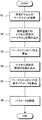
- FIG. 6 is a flowchart showing the operation of the data processing apparatus 100.
- step T1 measurement conditions are input to the data processing apparatus 100 (step T1). Then, an approximate expression obtained under the characteristics and measurement conditions prepared in advance for each pixel is fitted to the X-ray intensity data (step T2). Thereby, a correction coefficient for uniformity correction of each pixel is obtained.
- each pixel should be set as a complementary pixel (step T3).
- the determination is made, for example, based on whether or not the noise distribution overlaps the energy range equal to or greater than the threshold. In this case, if noise is applied to the threshold value, the pixel information cannot be used, so that it can be determined that the complementary pixel should be set.
- a correction table is set so that the pixel is complemented by surrounding pixels without taking the X-ray intensity (step T4). If it is determined that the complementary pixel should not be set, the process proceeds to step T5. Then, the X-ray intensity is corrected using the obtained correction table (step T5).
- the above-described operation can be performed by causing the apparatus to execute a program.
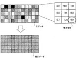
- FIG. 7 is a schematic diagram showing a correction method using the data processing apparatus.
- the count of each pixel using the measurement conditions such as the characteristics of each pixel of the detector and the gain, RICE position, temperature, and ⁇ (time constant for counting off) measured by the detector.
- An approximate expression representing the value is calculated.
- the correction table C1 for the detector is generated by fitting the approximate expression to the X-ray intensity.
- the X-ray intensity data M1 measured by the detector can be corrected to obtain corrected data M2.
- FIG. 8 is a graph showing the obtained integration profile.
- the integral profile shifts depending on the temperature, the variation in the insensitive layer thickness of the detector, the type of the X-ray source, and the like. For example, the zero point shifts with temperature, the counting rate changes with variations in temperature and dead layer thickness, and the gain changes with temperature.
- the integral profile can also be affected by atmospheric pressure, humidity, and the like. For example, since the absorption rate of X-rays from the X-ray source to the detector changes when the atmospheric pressure changes, the count intensity decreases when the atmospheric pressure is high, and the count intensity increases when the atmospheric pressure is low.
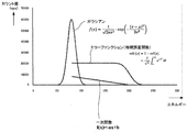
- FIG. 9 is a graph showing each term of the approximate expression.
- the count due to noise can be approximated by Gaussian as shown in Equation (1).
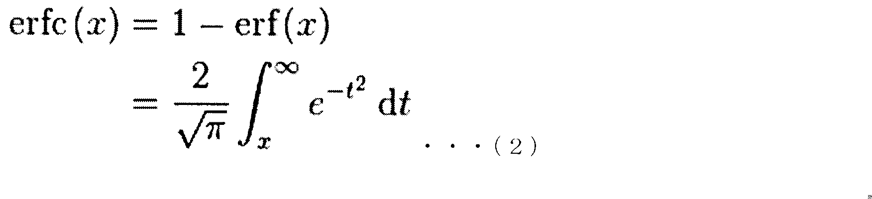
- the counts other than noise can be approximated by an error function (complementary error function) as shown in Equation (2).
- the count by charge sharing can be approximated by a linear function represented by Expression (3). Note that the above formulas are representative examples, and the formulas representing the respective counts are not necessarily limited to these.
- the count by the original X-ray irradiation can be expressed as the formula (4).
- the detected amount caused by charge sharing is evaluated as a linear function of the difference between the peak energy on the high energy side and the target energy.
- the target energy is energy for calculating the detected amount where charge sharing has occurred.
- charge sharing is evaluated by superimposing diffraction data expected to be detected by charge sharing of diffraction data on the high energy side, and the count by the original X-ray irradiation is calculated. It can also be expressed as Equation (5).
- FIG. 10 is a graph showing the result of fitting an approximate expression to an integral profile.
- an approximate profile Co obtained by adding the Gaussian G, the error function Erf, and the linear function Lf can be fitted to the profile Ex as the experimental result.
- a correction coefficient can be obtained from the coefficient obtained at that time to generate a correction table.
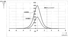
- FIG. 11 is a graph showing an example of a noise integration profile. As shown in FIG. 11, even when the threshold is set at a position (edge of the skirt) that is not affected by noise when exposed for 10 seconds, the noise when exposed for 20 seconds falls within the affected range. End up. In this way, depending on the position of the threshold, the pixel becomes a setting target of the complementary pixel.
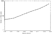
- FIG. 12 is a graph showing the number of defective pixels with respect to the measurement time. As the exposure time increases as described above, the noise profile overlaps even with the threshold at the same position. As shown in FIG. 12, as the measurement time increases, the number of defective pixels also increases, and a correction table that compensates for this can be provided.
Landscapes
- Physics & Mathematics (AREA)
- Health & Medical Sciences (AREA)
- Life Sciences & Earth Sciences (AREA)
- General Physics & Mathematics (AREA)
- High Energy & Nuclear Physics (AREA)
- Molecular Biology (AREA)
- Spectroscopy & Molecular Physics (AREA)
- Measurement Of Radiation (AREA)
- Apparatus For Radiation Diagnosis (AREA)
Abstract
Description
図1は、データ処理装置100の構成を示すブロック図である。例えば、データ処理装置100は、PCで構成され測定装置に接続されている。図1に示すように、データ処理装置100は、測定条件記憶部110、補正テーブル生成部120、特性記憶部130、近似式記憶部140、測定データ記憶部150、補正部160および出力部170を備えており、検出器で測定されたX線強度データを補正する。検出器は、ピクセル(ストリップを含む)の空間的最小単位を持つ1次元または2次元の検出器であって、電子回路ノイズを閾値で除去して光子をカウントするものである。
次に、予め検出器のピクセル毎に特性を準備する方法を説明する。図2は、事前に各ピクセルの特性を設定する方法を示すフローチャートである。まず、測定条件を変えてX線を検出器に一様照射し、各ピクセルの検出値を記録し、記録された検出値を用いて、ピクセル毎のベースラインを測定する(ステップS1)。ベースラインは、例えば、他のピクセルも含めて求められた平均値である。
上記の一様照射について説明する。図3は、検出器220への一様な照射の場面を示す斜視図である。X線の一様照射は、例えば、図3に示すような拡散板210で一様に拡散させたX線ビームB1を検出器220に向けて照射することで行うことができる。このようにして、ピクセル毎にX線の積分プロファイルを得ることができる。
上記のようにして得られたピクセル毎の特性を用いて、測定条件に応じた補正テーブルを準備することができる。図6は、データ処理装置100の動作を示すフローチャートである。
図7は、データ処理装置を用いた補正方法を示す概略図である。図7に示すように、検出器の各ピクセルの特性および検出器で測定された際のゲイン、RICE位置、温度、τ(数え落としの時定数)等の測定条件を用いて各ピクセルでのカウント値を表す近似式を算出する。そして、近似式をX線強度にフィッティングすることで、検出器に対する補正テーブルC1を生成する。そして、生成された補正テーブルC1を用いて、検出器で測定されたX線強度データM1を補正し、補正後データM2を得ることができる。
以下に近似式を用いて補正係数を算出する際のフィッティングについて説明する。図8は、得られた積分プロファイルを示すグラフである。図8に示すように、積分プロファイルは、温度、検出器の不感層厚のバラツキ、X線源の種類等により、シフトする。例えば、ゼロ点は温度によりシフトし、カウンティングレートは温度や不感層厚のバラツキにより変化し、ゲインは温度により変化する。また、積分プロファイルは、気圧、湿度等にも影響されうる。例えば、気圧が変わるとX線源から検出器までのX線の吸収率が変わるため、気圧が高い場合にはカウント強度が小さくなり、気圧が低い場合にはカウント強度が大きくなる。



以下にノイズへの対応を説明する。図11は、ノイズの積分プロファイルの例を示すグラフである。図11に示すように、10秒露光した場合のノイズの影響を受けない位置(裾野の端)に設けた閾値であっても、20秒露光した場合のノイズについては、影響を受ける範囲に入ってしまう。このようにして、閾値の位置次第でピクセルが補完ピクセルの設定対象となる。
110 測定条件記憶部
120 補正テーブル生成部
130 特性記憶部
140 近似式記憶部
150 測定データ記憶部
160 補正部
170 出力部
210 拡散板
220 検出器
B1 X線ビーム
C1 補正テーブル
Co 近似式のプロファイル
Erf エラーファンクション
Ex 実験結果のプロファイル
G ガウシアン
Lf 一次関数
M1 X線強度データ
M2 補正後データ
Claims (10)
- ピクセル検出器で測定されたX線強度データを補正するデータ処理装置であって、
特定の検出器の各ピクセルの特性を記憶する特性記憶部と、
前記特定の検出器で測定された際のものとして入力された測定条件および前記各ピクセルの特性を表す値を、前記各ピクセルでのカウント値を表す近似式に適用し、前記近似式の計算結果を用いて、前記特定の検出器に対する補正テーブルを生成する補正テーブル生成部と、
前記生成された補正テーブルを用いて、前記特定の検出器で測定されたX線強度データを補正する補正部と、を備えることを特徴とするデータ処理装置。 - 前記補正テーブル生成部は、前記各ピクセルでのカウント値を表す近似式として、本来のX線照射によるカウント分を表す数式とチャージシェアリングによるカウント分を表す数式とを足し合わせた数式を用いることを特徴とする請求項1記載のデータ処理装置。
- 前記補正テーブル生成部は、前記本来のX線照射によるカウント分を表す近似式として、ノイズによるカウント分を表す数式とノイズ以外によるカウント分を表す数式とを足し合わせた数式を用いることを特徴とする請求項2記載のデータ処理装置。
- 前記補正テーブル生成部は、各ピクセルに対して前記各ピクセルでのカウント値を表す近似式の計算結果を用いて一様性補正または歪み補正のための補正係数を算出することを特徴とする請求項1から請求項3のいずれかに記載のデータ処理装置。
- 前記補正テーブル生成部は、前記各ピクセルでのカウント値を表す近似式の計算結果およびカウント値の閾値を用いて不良ピクセルを特定し、前記不良ピクセルを補うための補正係数を算出することを特徴とする請求項1から請求項4のいずれかに記載のデータ処理装置。
- 前記入力された測定時の測定条件には、測定装置周辺の温度が含まれることを特徴とする請求項1から請求項5のいずれかに記載のデータ処理装置。
- 前記入力された測定時の測定条件には、測定に用いられるX線の線源の種類が含まれることを特徴とする請求項1から請求項6のいずれかに記載のデータ処理装置。
- 請求項1から請求項7のいずれかに記載のデータ処理装置に記憶され前記各ピクセルの特性を求める方法であって、
特定の測定条件を変えてX線を前記特定の検出器に一様照射し、各ピクセルの検出値を記録するステップと、
前記記録された各ピクセルの検出値から、各ピクセルの特性を算出するステップと、を含むことを特徴とする方法。 - ピクセル検出器で測定されたX線強度データを補正するデータ処理の方法であって、
特定の検出器で測定された際のものとして入力された測定条件および予め記憶された特定の検出器の各ピクセルの特性を表す値を、前記各ピクセルでのカウント値を表す近似式に適用し、前記各ピクセルでのカウント値を表す近似式の計算結果を用いて、前記特定の検出器に対する補正テーブルを生成するステップと、
前記生成された補正テーブルを用いて、前記特定の検出器で測定されたX線強度データを補正するステップと、を含むことを特徴とする方法。 - ピクセル検出器で測定されたX線強度データを補正するデータ処理のプログラムであって、
特定の検出器で測定された際のものとして入力された測定条件および予め記憶された特定の検出器の各ピクセルの特性を表す値を、前記各ピクセルでのカウント値を表す近似式に適用し、前記各ピクセルでのカウント値を表す近似式の計算結果を用いて、前記特定の検出器に対する補正テーブルを生成する処理と、
前記生成された補正テーブルを用いて、前記特定の検出器で測定されたX線強度データを補正する処理と、をコンピュータに実行させることを特徴とするプログラム。
Priority Applications (4)
| Application Number | Priority Date | Filing Date | Title |
|---|---|---|---|
| CN201580045810.1A CN106796298B (zh) | 2014-10-24 | 2015-07-10 | 数据处理装置、求取各像素的特性的方法以及数据处理的方法及程序 |
| EP15853380.2A EP3211456B1 (en) | 2014-10-24 | 2015-07-10 | Data processing apparatus, method of data processing, and computer program |
| US15/516,777 US10551510B2 (en) | 2014-10-24 | 2015-07-10 | Data processing apparatus, method of obtaining characteristic of each pixel and method of data processing, and program |
| JP2016555103A JP6524473B2 (ja) | 2014-10-24 | 2015-07-10 | データ処理装置、各ピクセルの特性を求める方法ならびにデータ処理の方法およびプログラム |
Applications Claiming Priority (2)
| Application Number | Priority Date | Filing Date | Title |
|---|---|---|---|
| JP2014217751 | 2014-10-24 | ||
| JP2014-217751 | 2014-10-24 |
Publications (1)
| Publication Number | Publication Date |
|---|---|
| WO2016063586A1 true WO2016063586A1 (ja) | 2016-04-28 |
Family
ID=55760636
Family Applications (1)
| Application Number | Title | Priority Date | Filing Date |
|---|---|---|---|
| PCT/JP2015/069924 Ceased WO2016063586A1 (ja) | 2014-10-24 | 2015-07-10 | データ処理装置、各ピクセルの特性を求める方法ならびにデータ処理の方法およびプログラム |
Country Status (5)
| Country | Link |
|---|---|
| US (1) | US10551510B2 (ja) |
| EP (1) | EP3211456B1 (ja) |
| JP (1) | JP6524473B2 (ja) |
| CN (1) | CN106796298B (ja) |
| WO (1) | WO2016063586A1 (ja) |
Cited By (2)
| Publication number | Priority date | Publication date | Assignee | Title |
|---|---|---|---|---|
| JP2019074423A (ja) * | 2017-10-17 | 2019-05-16 | 株式会社リガク | 処理装置、方法およびプログラム |
| WO2021153107A1 (ja) | 2020-01-27 | 2021-08-05 | 株式会社リガク | 制御装置、システム、方法およびプログラム |
Families Citing this family (5)
| Publication number | Priority date | Publication date | Assignee | Title |
|---|---|---|---|---|
| JP6524473B2 (ja) * | 2014-10-24 | 2019-06-05 | 株式会社リガク | データ処理装置、各ピクセルの特性を求める方法ならびにデータ処理の方法およびプログラム |
| JP6775777B2 (ja) * | 2017-08-29 | 2020-10-28 | 株式会社リガク | X線回折測定における測定結果の表示方法 |
| EP3508887A1 (en) * | 2018-01-09 | 2019-07-10 | Koninklijke Philips N.V. | Charge sharing calibration method and system |
| CN108490480B (zh) * | 2018-03-22 | 2019-10-29 | 北京大学 | 空间粒子探测器及其星上数据处理方法 |
| CN114324421B (zh) * | 2021-12-06 | 2023-06-27 | 武汉联影生命科学仪器有限公司 | 数据校正方法、装置、计算机设备和存储介质 |
Citations (5)
| Publication number | Priority date | Publication date | Assignee | Title |
|---|---|---|---|---|
| JPS5366778A (en) * | 1976-11-26 | 1978-06-14 | Mitsubishi Electric Corp | Meter using radioactive rays |
| JP2002000593A (ja) * | 2000-06-23 | 2002-01-08 | Canon Inc | 撮影装置、撮影システム、撮影方法、及び記憶媒体 |
| JP2008167846A (ja) * | 2007-01-10 | 2008-07-24 | Toshiba Corp | X線透過像表示システム |
| JP2010074641A (ja) * | 2008-09-19 | 2010-04-02 | Konica Minolta Medical & Graphic Inc | 放射線画像検出器、欠陥画素判定システム及び欠陥画素判定プログラム |
| JP2011180095A (ja) * | 2010-03-03 | 2011-09-15 | Fujifilm Corp | 放射線画像撮影装置、放射線画像撮影システム、およびプログラム |
Family Cites Families (18)
| Publication number | Priority date | Publication date | Assignee | Title |
|---|---|---|---|---|
| US4992706A (en) * | 1990-02-21 | 1991-02-12 | North American Philips Corporation | CRT raster distortion correction circuit |
| DE69116905T2 (de) | 1990-03-13 | 1996-06-13 | Sony Corp., Tokio/Tokyo | Schattierungseffektenkorrekturvorrichtung |
| US5640436A (en) * | 1995-01-26 | 1997-06-17 | Hitachi Medical Corporation | Method and apparatus for X-ray computed tomography |
| US6134292A (en) * | 1998-07-13 | 2000-10-17 | General Electric Company | Methods and apparatus for reducing z-axis non-uniformity artifacts |
| US6476394B1 (en) * | 1999-11-26 | 2002-11-05 | Konica Corporation | Radiation image capturing apparatus |
| US6792159B1 (en) | 1999-12-29 | 2004-09-14 | Ge Medical Systems Global Technology Company, Llc | Correction of defective pixels in a detector using temporal gradients |
| US6694172B1 (en) * | 2001-06-23 | 2004-02-17 | Koninklijke Philips Electronics, N.V. | Fault-tolerant detector for gamma ray imaging |
| DE102004025121A1 (de) | 2004-05-21 | 2005-12-15 | Bruker Axs Gmbh | Verfahren zum Betrieb eines Röntgenanalysegeräts mit zweidimensionalem Array-Detektor und Röntgenanalysegerät zum Durchführen des Verfahrens |
| WO2007125691A1 (ja) | 2006-04-28 | 2007-11-08 | Hitachi Medical Corporation | X線画像診断装置 |
| JP5455857B2 (ja) * | 2010-09-28 | 2014-03-26 | 富士フイルム株式会社 | 放射線画像撮影装置、放射線画像撮影方法、及び放射線画像撮影プログラム |
| CN101975965B (zh) * | 2010-10-27 | 2012-07-25 | 江苏康众数字医疗设备有限公司 | 平板探测器及其温度校准方法与图像校正方法 |
| CN102346260B (zh) * | 2011-06-08 | 2013-12-18 | 上海奕瑞光电子科技有限公司 | 具有温度感应功能的平板x射线探测器及其制备方法 |
| DE102011077859B4 (de) * | 2011-06-21 | 2014-01-23 | Siemens Aktiengesellschaft | Quantenzählender Strahlungsdetektor |
| JP5914381B2 (ja) * | 2013-02-19 | 2016-05-11 | 株式会社リガク | X線データ処理装置、x線データ処理方法およびx線データ処理プログラム |
| JP5816316B2 (ja) * | 2013-03-29 | 2015-11-18 | 富士フイルム株式会社 | 放射線画像検出装置およびその作動方法、並びに放射線撮影装置 |
| KR20140137715A (ko) * | 2013-05-23 | 2014-12-03 | 삼성디스플레이 주식회사 | 엑스레이 검출 장치 및 방법 |
| US20150085970A1 (en) * | 2013-09-23 | 2015-03-26 | General Electric Company | Systems and methods for hybrid scanning |
| JP6524473B2 (ja) * | 2014-10-24 | 2019-06-05 | 株式会社リガク | データ処理装置、各ピクセルの特性を求める方法ならびにデータ処理の方法およびプログラム |
-
2015
- 2015-07-10 JP JP2016555103A patent/JP6524473B2/ja active Active
- 2015-07-10 EP EP15853380.2A patent/EP3211456B1/en active Active
- 2015-07-10 US US15/516,777 patent/US10551510B2/en active Active
- 2015-07-10 WO PCT/JP2015/069924 patent/WO2016063586A1/ja not_active Ceased
- 2015-07-10 CN CN201580045810.1A patent/CN106796298B/zh active Active
Patent Citations (5)
| Publication number | Priority date | Publication date | Assignee | Title |
|---|---|---|---|---|
| JPS5366778A (en) * | 1976-11-26 | 1978-06-14 | Mitsubishi Electric Corp | Meter using radioactive rays |
| JP2002000593A (ja) * | 2000-06-23 | 2002-01-08 | Canon Inc | 撮影装置、撮影システム、撮影方法、及び記憶媒体 |
| JP2008167846A (ja) * | 2007-01-10 | 2008-07-24 | Toshiba Corp | X線透過像表示システム |
| JP2010074641A (ja) * | 2008-09-19 | 2010-04-02 | Konica Minolta Medical & Graphic Inc | 放射線画像検出器、欠陥画素判定システム及び欠陥画素判定プログラム |
| JP2011180095A (ja) * | 2010-03-03 | 2011-09-15 | Fujifilm Corp | 放射線画像撮影装置、放射線画像撮影システム、およびプログラム |
Non-Patent Citations (1)
| Title |
|---|
| See also references of EP3211456A4 * |
Cited By (3)
| Publication number | Priority date | Publication date | Assignee | Title |
|---|---|---|---|---|
| JP2019074423A (ja) * | 2017-10-17 | 2019-05-16 | 株式会社リガク | 処理装置、方法およびプログラム |
| WO2021153107A1 (ja) | 2020-01-27 | 2021-08-05 | 株式会社リガク | 制御装置、システム、方法およびプログラム |
| US12405390B2 (en) | 2020-01-27 | 2025-09-02 | Rigaku Corporation | Control apparatus, system, method, and program |
Also Published As
| Publication number | Publication date |
|---|---|
| CN106796298B (zh) | 2020-01-21 |
| EP3211456B1 (en) | 2026-04-29 |
| US20180203132A1 (en) | 2018-07-19 |
| JPWO2016063586A1 (ja) | 2017-08-03 |
| EP3211456A1 (en) | 2017-08-30 |
| EP3211456A4 (en) | 2018-07-11 |
| US10551510B2 (en) | 2020-02-04 |
| JP6524473B2 (ja) | 2019-06-05 |
| CN106796298A (zh) | 2017-05-31 |
Similar Documents
| Publication | Publication Date | Title |
|---|---|---|
| JP6524473B2 (ja) | データ処理装置、各ピクセルの特性を求める方法ならびにデータ処理の方法およびプログラム | |
| JP6133231B2 (ja) | X線エネルギースペクトル測定方法およびx線エネルギースペクトル測定装置およびx線ct装置 | |
| US9916656B2 (en) | Method for processing radiographic image and radiography system | |
| US10245003B2 (en) | Radiation imaging apparatus, radiation imaging system, radiation detection apparatus, imaging control apparatus, imaging control method, and storage medium | |
| US20160070008A1 (en) | Count-weighted least squares parameter estimation for a photon-counting detector | |
| US10194881B2 (en) | Radiographic image processing device, method, and recording medium | |
| KR101874235B1 (ko) | 방사능의 추정 방법 | |
| US9453924B2 (en) | Radiation control apparatus and method for acquiring correction data for an imaging device | |
| US20220091050A1 (en) | Image processing apparatus, image processing method, and storage medium | |
| Haefner | MTF measurements, identifying bias, and estimating uncertainty | |
| CN106644078A (zh) | 一种用于太赫兹图像非均匀性校正的方法 | |
| JP6772838B2 (ja) | 画像情報処理装置、画像情報処理システム、画像情報処理方法、及び、画像情報処理プログラム | |
| US20230404510A1 (en) | Radiation image processing device, radiation image processing method, and radiation image processing program | |
| KR102582334B1 (ko) | 화상 처리 방법 및 화상 처리 장치 | |
| JP5483832B2 (ja) | 放射線撮影制御装置および方法 | |
| JP2017062178A (ja) | 製品の欠陥検出方法 | |
| US20220401051A1 (en) | Radiation imaging system, image processing apparatus, image processing method, and non-transitory computer readable storage medium | |
| Bouchard et al. | Eigencolor radiochromic film dosimetry | |
| He et al. | Error analysis of laser beam quality measured with CCD sensor and choice of the optimal threshold | |
| KR101690096B1 (ko) | 열영상 카메라의 온도 데이터 측정장치 | |
| KR101637552B1 (ko) | 렌즈에 의한 불균일 영상 보정 장치 및 그 방법 | |
| US11302042B2 (en) | Method for correcting nonlinearities of image data of at least one radiograph, and computed tomography device | |
| CN117553925A (zh) | 一种红外测量图像的非均匀性矫正方法及装置 | |
| JP2018057669A (ja) | 放射線撮影装置、放射線撮影システム、放射線撮影方法、及びプログラム | |
| Xie et al. | Analysis and modeling of radiometric error caused by imaging blur in optical remote sensing systems |
Legal Events
| Date | Code | Title | Description |
|---|---|---|---|
| 121 | Ep: the epo has been informed by wipo that ep was designated in this application |
Ref document number: 15853380 Country of ref document: EP Kind code of ref document: A1 |
|
| ENP | Entry into the national phase |
Ref document number: 2016555103 Country of ref document: JP Kind code of ref document: A |
|
| REEP | Request for entry into the european phase |
Ref document number: 2015853380 Country of ref document: EP |
|
| WWE | Wipo information: entry into national phase |
Ref document number: 2015853380 Country of ref document: EP |
|
| WWE | Wipo information: entry into national phase |
Ref document number: 15516777 Country of ref document: US |
|
| NENP | Non-entry into the national phase |
Ref country code: DE |