WO2016063367A1 - Electric power steering device - Google Patents
Electric power steering device Download PDFInfo
- Publication number
- WO2016063367A1 WO2016063367A1 PCT/JP2014/078054 JP2014078054W WO2016063367A1 WO 2016063367 A1 WO2016063367 A1 WO 2016063367A1 JP 2014078054 W JP2014078054 W JP 2014078054W WO 2016063367 A1 WO2016063367 A1 WO 2016063367A1
- Authority
- WO
- WIPO (PCT)
- Prior art keywords
- circuit
- motor
- abnormality
- electric power
- power steering
- Prior art date
Links
Images


Classifications
-
- B—PERFORMING OPERATIONS; TRANSPORTING
- B62—LAND VEHICLES FOR TRAVELLING OTHERWISE THAN ON RAILS
- B62D—MOTOR VEHICLES; TRAILERS
- B62D5/00—Power-assisted or power-driven steering
- B62D5/04—Power-assisted or power-driven steering electrical, e.g. using an electric servo-motor connected to, or forming part of, the steering gear
- B62D5/0457—Power-assisted or power-driven steering electrical, e.g. using an electric servo-motor connected to, or forming part of, the steering gear characterised by control features of the drive means as such
- B62D5/0481—Power-assisted or power-driven steering electrical, e.g. using an electric servo-motor connected to, or forming part of, the steering gear characterised by control features of the drive means as such monitoring the steering system, e.g. failures
- B62D5/0484—Power-assisted or power-driven steering electrical, e.g. using an electric servo-motor connected to, or forming part of, the steering gear characterised by control features of the drive means as such monitoring the steering system, e.g. failures for reaction to failures, e.g. limp home
-
- B—PERFORMING OPERATIONS; TRANSPORTING
- B62—LAND VEHICLES FOR TRAVELLING OTHERWISE THAN ON RAILS
- B62D—MOTOR VEHICLES; TRAILERS
- B62D5/00—Power-assisted or power-driven steering
- B62D5/04—Power-assisted or power-driven steering electrical, e.g. using an electric servo-motor connected to, or forming part of, the steering gear
- B62D5/0457—Power-assisted or power-driven steering electrical, e.g. using an electric servo-motor connected to, or forming part of, the steering gear characterised by control features of the drive means as such
- B62D5/046—Controlling the motor
-
- B—PERFORMING OPERATIONS; TRANSPORTING
- B62—LAND VEHICLES FOR TRAVELLING OTHERWISE THAN ON RAILS
- B62D—MOTOR VEHICLES; TRAILERS
- B62D5/00—Power-assisted or power-driven steering
- B62D5/04—Power-assisted or power-driven steering electrical, e.g. using an electric servo-motor connected to, or forming part of, the steering gear
- B62D5/0457—Power-assisted or power-driven steering electrical, e.g. using an electric servo-motor connected to, or forming part of, the steering gear characterised by control features of the drive means as such
- B62D5/0481—Power-assisted or power-driven steering electrical, e.g. using an electric servo-motor connected to, or forming part of, the steering gear characterised by control features of the drive means as such monitoring the steering system, e.g. failures
- B62D5/0487—Power-assisted or power-driven steering electrical, e.g. using an electric servo-motor connected to, or forming part of, the steering gear characterised by control features of the drive means as such monitoring the steering system, e.g. failures detecting motor faults
-
- H—ELECTRICITY
- H02—GENERATION; CONVERSION OR DISTRIBUTION OF ELECTRIC POWER
- H02P—CONTROL OR REGULATION OF ELECTRIC MOTORS, ELECTRIC GENERATORS OR DYNAMO-ELECTRIC CONVERTERS; CONTROLLING TRANSFORMERS, REACTORS OR CHOKE COILS
- H02P25/00—Arrangements or methods for the control of AC motors characterised by the kind of AC motor or by structural details
- H02P25/16—Arrangements or methods for the control of AC motors characterised by the kind of AC motor or by structural details characterised by the circuit arrangement or by the kind of wiring
- H02P25/22—Multiple windings; Windings for more than three phases
-
- H—ELECTRICITY
- H02—GENERATION; CONVERSION OR DISTRIBUTION OF ELECTRIC POWER
- H02P—CONTROL OR REGULATION OF ELECTRIC MOTORS, ELECTRIC GENERATORS OR DYNAMO-ELECTRIC CONVERTERS; CONTROLLING TRANSFORMERS, REACTORS OR CHOKE COILS
- H02P27/00—Arrangements or methods for the control of AC motors characterised by the kind of supply voltage
- H02P27/04—Arrangements or methods for the control of AC motors characterised by the kind of supply voltage using variable-frequency supply voltage, e.g. inverter or converter supply voltage
- H02P27/06—Arrangements or methods for the control of AC motors characterised by the kind of supply voltage using variable-frequency supply voltage, e.g. inverter or converter supply voltage using dc to ac converters or inverters
-
- H—ELECTRICITY
- H02—GENERATION; CONVERSION OR DISTRIBUTION OF ELECTRIC POWER
- H02P—CONTROL OR REGULATION OF ELECTRIC MOTORS, ELECTRIC GENERATORS OR DYNAMO-ELECTRIC CONVERTERS; CONTROLLING TRANSFORMERS, REACTORS OR CHOKE COILS
- H02P29/00—Arrangements for regulating or controlling electric motors, appropriate for both AC and DC motors
- H02P29/02—Providing protection against overload without automatic interruption of supply
- H02P29/024—Detecting a fault condition, e.g. short circuit, locked rotor, open circuit or loss of load
- H02P29/028—Detecting a fault condition, e.g. short circuit, locked rotor, open circuit or loss of load the motor continuing operation despite the fault condition, e.g. eliminating, compensating for or remedying the fault
-
- H—ELECTRICITY
- H02—GENERATION; CONVERSION OR DISTRIBUTION OF ELECTRIC POWER
- H02P—CONTROL OR REGULATION OF ELECTRIC MOTORS, ELECTRIC GENERATORS OR DYNAMO-ELECTRIC CONVERTERS; CONTROLLING TRANSFORMERS, REACTORS OR CHOKE COILS
- H02P29/00—Arrangements for regulating or controlling electric motors, appropriate for both AC and DC motors
- H02P29/02—Providing protection against overload without automatic interruption of supply
- H02P29/032—Preventing damage to the motor, e.g. setting individual current limits for different drive conditions
Definitions
- the present invention particularly relates to an electric power steering apparatus having a redundant configuration of a motor and a control unit.
- a motor is provided with two sets of coil windings, and a control unit having two sets of inverter circuits capable of independently driving the two sets of coil windings is provided.
- a control unit having two sets of inverter circuits capable of independently driving the two sets of coil windings.
- the present invention has been made to solve the above-described problems of the conventional apparatus, has a redundant system that also considers mountability, and continues motor control in the event of an abnormality in substantially the same manner as in a normal state. It is an object of the present invention to provide an electric power steering device that can reliably perform the operation.
- An electric power steering apparatus includes a stator having two independent coil windings for a single rotor, a motor that rotates a steering mechanism of a vehicle, and a motor that is integrally attached to the motor.
- the control unit section includes a power supply circuit that generates a constant voltage, an input circuit that inputs operation information of each circuit, an output circuit that drives a coil winding of the motor, and the output circuit
- a power supply relay circuit that cuts off current supply to the power supply circuit
- a central processing unit that calculates a control amount based on information from the input circuit and outputs a control signal to the output circuit, and each of the coil windings of the motor
- Two systems are formed so as to supply or cut off current independently, and the central processing unit has an abnormality detection function for detecting an abnormality of each circuit or the coil winding. To communicate between the two central processing units, when an abnormality in one system has been detected, it is configured to continue the control in the control unit of the other system.
- the electric power steering apparatus can be reduced in size by mounting two sets of control units coaxially with respect to the output shaft of the motor.
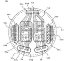
- FIG. 3 is a top view illustrating a configuration of a main part of the electric power steering device as viewed from the control unit side in FIG. 2. It is a top view which shows the control board of the electric power steering apparatus in FIG. It is a flowchart explaining operation
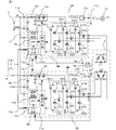
- FIG. 1 is a circuit diagram showing a main configuration of an electric system of an electric power steering apparatus.
- control units 1a and 1b drive and control a motor 2 having two sets of three-phase coil windings, and steer a handle.
- CPU central processing unit
- control circuit units 4a and 4b power is supplied from the battery 9 mounted on the vehicle to the control circuit units 4a and 4b via the ignition switch 7 and the power supply circuits 13a and 13b. Further, for example, information such as a torque sensor mounted near the steering wheel for detecting the steering torque of the steering wheel and a speed sensor for detecting the traveling speed of the vehicle is input from the sensor 8 to the control circuit units 4a and 4b.
- the control units 1a and 1b are provided with a large number of terminals (17a, 17b, and 17c) for connecting to external devices, and are specifically arranged by fixing the connectors to the circuit board.
- Information from the sensor 8 is transmitted to the CPUs 10a and 10b via the input circuits 12a and 12b of the control circuit units 4a and 4b.
- CPU10a, 10b calculates the electric current value for rotating the motor 2 based on this input information, and outputs a control signal to drive circuit 11a, 11b.
- the drive circuits 11a and 11b each receive an input signal and output a control signal for controlling each switching element of the inverter circuits 3a and 3b constituting the output circuit. Since only a small current flows through the drive circuits 11a and 11b, the drive circuits 11a and 11b are arranged in the control circuit units 4a and 4b, but may be arranged in the inverter circuits 3a and 3b.
- the inverter circuits 3a and 3b have the same circuit configuration with respect to the coil windings (U1, V1, W1) and (U2, V2, W2) of each phase, and are independent of each phase coil winding. The current is supplied.
- the inverter circuits 3a and 3b include upper and lower arm switching elements (31U, 31V, 31W) for supplying output current to the three-phase coil windings (U1, V1, W1) (U2, V2, W2) of the motor 2, respectively.
- the potential difference between both terminals of the shunt resistors 33U, 33V, and 33W, and the voltage of the coil winding terminal of the motor 2, for example, are also input to the input circuits 12a and 12b. These pieces of information are also input to the CPUs 10a and 10b, and are configured to perform so-called feedback control by calculating the difference between the calculated current value and the detected value, and supplying the necessary motor current. Assist steering force. Control signals for the power relay switching elements 5a and 5b are also output, and the power supply to the motor 2 can be cut off by the power relay switching elements 5a and 5b. Similarly, the motor relay switching elements 34U, 34V, and 34W can also independently cut off the current supply to the motor 2, respectively.
- filters 6a and 6b including capacitors and coils are connected to the power supply terminals (+ B and GND) of the battery 9.
- the power relay switching elements 5a and 5b since a large current flows through the power relay switching elements 5a and 5b, heat is generated. Therefore, they are built in the inverter circuits 3a and 3b, coupled to the radiators of the inverter circuits 3a and 3b, and radiated. Also good.
- CPU10a, 10b is equipped with the abnormality detection function which detects abnormality, such as inverter circuit 3a, 3b, coil winding (U1, V1, W1), (U2, V2, W2), from various input information.
- abnormality such as inverter circuit 3a, 3b, coil winding (U1, V1, W1), (U2, V2, W2)
- the CPUs 10a and 10b are configured to supply power to the notification device 15 such as a lamp through the drive circuits 16a and 16b to light them.
- the motor 2 is a brushless motor in which two sets of three-phase coil windings are delta-connected, and is equipped with rotation sensors 9a and 9b for detecting the rotational position of the rotor.
- the rotation sensors 9a and 9b are also equipped with two sets of sensors in order to secure a redundant system, and rotor rotation information is transmitted to the input circuits 12a and 12b of the control circuit units 4a and 4b, respectively.
- the motor 2 may be a star-connected brushless motor instead of a three-phase delta-connected brushless motor or a two-pole two-pair brushed motor.
- the specification of the coil winding may be distributed winding or concentrated winding as in the conventional device. However, it is necessary to configure such that only one set of coil windings or two sets of coil windings can output desired motor rotation speed and torque.
- control units 1a and 1b are configured such that the motor 2 can be independently driven using input information, a calculated value, and a detected value.
- a communication line 14 is connected between the CPUs 10a and 10b so that data and information can be exchanged.
- the operation state of the counterpart CPUs 10a and 10b can be grasped by transmitting and receiving information through the communication line 14, respectively. For example, it is possible to transmit to the CPU 10b that the CPU 10a has detected an abnormality and has turned off a predetermined switching element. If an abnormality occurs in the CPUs 10a and 10b themselves, it becomes impossible to send and receive periodic communication signals in a predetermined format, so that one CPU can grasp the occurrence of an abnormality in the other CPU.
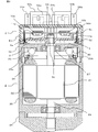
- FIG. 2 shows a structure in which the control unit unit 1 including the control units 1a and 1b is mounted on the upper side of the motor 2, and the control unit unit 1 and the motor 2 are integrated.
- the motor 2 includes a rotor 21 in which a permanent magnet (not shown) is mounted around an output shaft 23, and a stator 22 that is disposed to face the rotor 21 and has a three-phase coil winding 24 wound thereon.
- a reduction gear 28 for reducing the rotation of the motor 2 is attached to the motor output shaft 23, and the output is taken out from the lower direction in the figure.
- the extension windings 25a and 25b drawn from the three-phase coil windings 24 pass through the upper frame 50 in the upward direction. It has been extended.
- the control unit 1 is arranged on the upper coaxial line of the upper frame 50.
- the upper frame 50 is fixed to the yoke 26 of the motor 2 by press fitting or the like.
- the control unit 1 has a housing 51 made of, for example, insulating resin. Inside the housing 51, the power module 3 including inverter circuits 3a, 3b and the like that constitute an output circuit in close contact with the upper frame 50 is disposed, and one leg portion that is an input / output terminal of the inverter circuits 3a, 3b is disposed. The portion extends upward and is connected to the extension windings 25a and 25b. An intermediate member 52 and a control board 4c are stacked on the upper frame 50. The control board 4c is mounted with a large number of electronic components constituting the control circuit units 4a and 4b, but only the CPUs 10a and 10b and the drive circuits 11a and 11b are shown.
- the CPUs 10a and 10b are disposed symmetrically at the center of the control board 4c. Further, the drive circuits 11a and 11b are mounted on the lower surface of the control board 4c, and the power module 3 that constitutes the inverter circuits 3a and 3b is arranged facing the drive circuits 11a and 11b.
- the upper frame 50 is made of, for example, aluminum having good heat conductivity, and also acts as a heat sink by bringing the power module 3 into contact therewith.
- the power module 3 itself may have a structure with a built-in heat sink, but the built-in heat sink alone often does not provide sufficient heat dissipation, and the upper frame 50 having a larger area and volume has better heat dissipation.
- the yoke 26 is in contact with the upper frame 50, and the yoke 26 can also perform the heat radiation action of the motor 2 and the power module 3. Further, by exposing the outer periphery of the upper frame 50 and the yoke 26 to the outside, it is possible to improve heat dissipation.
- the upper frame 50 functions as a partition for partitioning the control unit 1 and the motor 2 and is configured to rotatably support the output shaft 23 via a bearing 27.
- the intermediate member 52 is attached so as to press the power module 3 downward, and the power module 3 is in close contact with the upper frame 50.
- the intermediate member 52 is provided with holes for positioning a large number of input / output terminal portions of the power module 3 and the extension windings 25a and 25b of the motor 2, and further for fixing the control board 4c at a predetermined interval.
- the column part 52a is provided.
- the intermediate member 52 is also provided with a power supply (+ B, GND) line and is connected to the power module 3.
- the output terminal of the power module 3 and the extended winding end of the coil winding of the motor 2 are drawn to the upper surface of the control board 4c and welded at this portion to be electrically connected.
- an output shaft 23 is provided through the center of the upper frame 50, and a magnet rotor 9 c is attached to the tip of the output shaft 23.
- rotation sensors 9a and 9b are mounted side by side on the control board 4c.
- a capacitor 30 is also mounted in the space between the lower surface of the upper frame 50 and the motor 2 coil winding, and this capacitor 30 is connected to the power supply terminal of the power module 3 via the intermediate member 52. (Not shown). Therefore, most of the control unit 1 is arranged above the upper frame 50, but a part of the capacitor 30 and the like can be arranged on the motor 2 side to effectively use the space.
- FIG. 3 shows the arrangement of the connectors as viewed from above.
- the power supply (+ B, GND) is supplied from terminals 53c and 53d, and is connected to the capacitors and coils of the filters 6a and 6b via the bus bars 53g and 53j (the bus bar is shown as a perspective view).
- sensor signal connectors 55a and 55b are arranged around the housing 51, and terminals 55c and 55d (perspective view) of the connectors 55a and 55b are extended into the control unit 1 and coupled to the control board 4c. Yes. Therefore, the terminals 55c and 55d are extended along the inner peripheral surface of the housing 51 and extend to the periphery of the control board 4c. Since a large number of electronic components are mounted on the control board 4c, connection terminals and bus bars are arranged on the periphery of the control board 4c, and are configured to be pulled in to the center by a wiring pattern. The area of 4c can be used effectively.
- the filters 6a and 6b are relatively large parts, they are not mounted on the control board 4c but are arranged on the upper surface of the housing 51 and covered with the covers 54a and 54b. It can be used effectively. Further, in the vicinity of the upper end of the housing 51, two sets of power bus bars 56c, 56d are arranged via power filters 6a, 6b, and are extended into the control unit 1 to be connected to the power module 3 and the power relay switch. Connected to the ring elements 5a and 5b. Further, a cover 56 is provided above the housing 51 to cover a connection portion between the four bus bars (53g, 53j) and the four bus bars (56c, 56d) extended from the control unit 1.
- two sets of connectors are independently arranged in the housing 51 substantially in parallel with each other, and are extended to the control unit 1 in the same manner through the inner periphery of the housing 51 while maintaining the independence of each part. ing. As a result, the overall area and volume of the control unit 1 can be reduced.
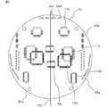
- FIG. 4 is a top view of the control board 4c as viewed from above, and shows only main electronic components.
- two sets of control circuits are mounted on a single control board 4c, and each component is arranged separately from the center line 4d to the left and right.
- a control circuit of a first system is mounted on the left side and a second system is mounted on the right side.
- Components of the power supply circuit 13b are mounted near the upper portion of the control board 4c, the CPU 10b is mounted below the components, and the input circuit 12b is mounted further below.
- the drive circuit 11b and the rotation sensor 9b are mounted on the back surface of the control board 4c.
- Three signal connector terminals 55d and three extension windings 25b from the motor 2 are arranged on the periphery of the control board 4c, and three output terminals of the power module 3 are also extended so as to come into contact therewith. These terminals are coupled by welding to electrically connect the power module 3 and the coil winding of the motor 2. Further, four holes are provided above the control board 4c for allowing the bus bars 56c and 56d of the power supply line (+ B, GND) to pass therethrough.
- the two sets of left and right circuit networks have the main parts arranged in almost the same arrangement, and therefore, the two sets of electrical inputs, arithmetic processing, and outputs have the same flow.
- it is substantially line symmetric with respect to the center line 4d of the control board 4c.
- the four circles on the control board 4 c are holes for inserting board fixing column parts 52 a extended from the intermediate member 52.
- the intermediate member 52 itself is fixed to the upper frame 50. That is, a space is reduced by forming a laminated structure of the upper frame 50, the power module 3, the intermediate member 52, and the control board 4c.
- two independent control units 1a and 1b are mounted on a single control board 4c in a single housing, and two control circuits are arranged in parallel. Furthermore, the electrical system is completely separated and independent from the connector which is the outermost part of the apparatus, and is configured to be complemented by the other control circuit when one of the control circuits is abnormal. Since the vehicle battery 9 is usually one, it is possible to use a single power connector 53a, 53b. Similarly, the filters 6a and 6b may be single, and the arrangement and wiring may be made into two complete systems from the electronic circuit portions in the control units 1a and 1b.
- the CPUs 10a and 10b and the input circuits 12a and 12b are built in the same package, and can perform the same function even if the internal circuits are double and independent.
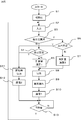
- step S1 RAM, ROM, port and the like are initialized.
- step S2 any information input via the input circuit 12a in step S2 is obtained and stored. This information includes communication data of the other party's CPU 10b.
- step S3 it is checked whether or not an abnormality is detected in the CPU 10b of the other party.
- the presence or absence of the other party's abnormality can be determined by decoding the communication data with the other party CPU 10b. If there is no abnormality in the counterpart CPU 10b (N: No), the presence or absence of own abnormality is checked in step S4. If no abnormality is detected (N), the process proceeds to step S5, and a normal control amount 1 at which no abnormality has occurred in both the CPUs 10a and 10b is calculated.
- step S6 if an abnormality has occurred in the other party in step S3 (Y: Yes), the process proceeds to step S6, and the presence or absence of own abnormality is checked as in step S4.
- step S11 if an abnormality has occurred in itself (Y), the process proceeds to step S11 to perform a process in case of an abnormality. If there is no abnormality in itself (N), the process proceeds to step S7, and the control amount 2 under the condition of the other party abnormality and self-normal is calculated. Thereafter, the process proceeds to step S8.
- step S4 when it is determined in step S4 or step S6 that an abnormality has occurred in the CPU 10a itself, the process proceeds to step S11, and a control signal is output so as to stop the output to the drive circuit 11a.
- a control signal is output so as to stop the output to the drive circuit 11a.
- step 11 it can be set so that a part of the control can be continuously processed in addition to the process at the time of abnormality in the entire stop state.
- a control amount calculation process is also required, and therefore it may be more efficient to perform the process in steps S5 and S7.
- step S 12 the abnormal state data is transmitted using the communication line 14.
- This data is transmitted including an abnormal level, for example, that all switching elements are in an OFF state.
- the control amount in this case including the ratio compared to the normal time, but such abnormal content communication is processed through steps S9 and S10. It is also possible. Thereby, the other party can grasp the content of the abnormality. Therefore, it is possible to correct and output the own control amount in accordance with the other party's abnormality.
- step S5 the current value required according to the vehicle speed and torque is calculated and divided into halves, as in the conventional device. This half current value is the control amount that one control unit is responsible for. Furthermore, the current supply current is detected from the potential difference of the shunt resistor 33, and is output as a control command value according to the difference between the target value and the detected value.
- step S7 since an abnormality has occurred in the counterpart system, it is necessary to supply the current value required only in the own system as the control amount calculation 2.
- the counterpart system is abnormal in only one phase and is driven in two phases, it is calculated so as to supply a current value of 2/3, and the control command value calculated thereby is output.
- control is performed so that all the calculated control amounts are output by the own system.
- a control amount for two-phase driving can be calculated in step S5 or step S7.
- the control amount can be obtained by calculating in almost the same procedure as in normal times and finally correcting for two-phase driving.
- both the CPUs 10a and 10b can execute the same procedure by changing only the distribution ratio, and the control logic can be simplified.
- step S8 a control command is output so that each switching element can be driven based on the control command value. Since the upper and lower switching elements of the inverter circuits 3a and 3b are subjected to pulse width modulation, a control signal corresponding to this is output.
- step S9 the presence or absence of abnormality is checked. Specifically, the current flowing by driving each switching element is detected by the shunt resistor 33, and the coil winding terminal voltage of the motor is monitored, and a predetermined voltage appears according to the driving of the switching element. By determining, an abnormality can be detected.
- the abnormality can be detected even with only one phase.
- the CPU 10a stores the abnormality state including the abnormal state, and communicates the abnormal state to the counterpart CPU 10b via the communication line 14 in step S10. If there is other necessary information, it is efficient to include it in this process and transmit it. For example, it is also possible to check the accuracy of mutual control amount calculation by exchanging information of the input circuit 12a and control amount information.
- step S13 the process waits for a predetermined time, for example, 5 milliseconds, and if the predetermined time has passed (Y), the process returns to step S2 and repeats the same procedure again to proceed with the process.
- each control unit takes charge of 1/2 to control the motor 2.
- the normal CPU is 100% even in the worst case. Control can be continued, and the driver does not have difficulty in steering.
- This notification can be realized, for example, by operating the notification device 15 in step S10 or step S12 based on the output at the time of abnormality in step S9 or step S11.
- the normal side can be set to three levels of 50, 65%, and 100%, and the abnormal side can be set to 50%, 35%, and 0%.
- the communication 1 and the communication 2 in steps S10 and S12 are provided independently at two places.
- the abnormality detection means of step S9 was arrange
- the switching element in each control unit 1a, 1b needs to sufficiently secure its heat dissipation in consideration of the case where it is driven 100%. Specifically, it is necessary to design in consideration of the current capacity of the element itself and the heat sink structure for heat dissipation. Also, in the motor 2, it is necessary to design the specifications of the coil and the magnet and the scale of each part so that the maximum torque for the desired number of rotations can be output with only one set of three-phase coil windings. Furthermore, heat dissipation can be improved by separating the control board 4c and the power module 3 and disposing the power module 3 that generates the most heat away from the control board 4c.
- the power module 3 is provided with a heat sink, and this heat sink is brought into close contact with another heat sink (upper frame 50) having a large heat radiation area and volume, and is brought into contact with the yoke 26 so that heat of the power module is transferred to the yoke 26. It has a structure to let you. For this reason, the yoke 26 is also made of aluminum with good heat dissipation, and the heat dissipation of the motor 2 itself can be improved. In addition, when one of them becomes abnormal, since the heat sink (upper frame 50) is single, the entire heat sink can be used with only one system, and the heat dissipation can be improved.
- this single heat sink (upper frame 50) can also eliminate the unevenness of heat and achieve a uniform heat distribution. Further, by exposing the outer periphery of this heat sink as the outermost layer of the device, further heat dissipation can be achieved. It is possible to contribute to improving the performance.
- FIG. 6 is a drawing corresponding to FIG. 2 of the first embodiment, and the same reference numerals indicate the same or corresponding parts.
- the overall circuit diagram is also the same as FIG. FIG. 6 shows a state where the pair of power modules 3 are arranged in parallel to the output shaft 23.
- the motor 2 is the same as that shown in FIG.
- a magnet rotor 9 c is mounted on the opposite end of the output shaft 23 of the motor 2 as a rotation sensor, and is rotated in synchronization with the output shaft 23.
- the upper frame 50 has a substantially cylindrical shape, and a bottom portion that partitions the control unit portion 1 and the motor 2 is formed.
- a bearing 27 for rotatably supporting the output shaft 23 is mounted at the center of the bottom. Further, a part of the outer periphery of the cylindrical portion has a concavo-convex wall portion 50a to increase the surface area and improve heat dissipation. Both power modules 3 are in contact with the inside of the wall portion, and the heat conductivity of the power module 3 is improved. Both power modules 3 are arranged vertically on the side wall of the upper frame 50, which is different from the horizontal placement of FIG. 2. A sensor substrate 4 e is mounted between the power modules 3 together with the intermediate member 52.
- Two sets of rotation sensors 9a and 9b for detecting the rotation of the permanent magnet mounted on the magnet rotor 9c are mounted at the center of the sensor board 4e, and the rotation sensors 9a and 9b are independently rotated to the CPUs 10a and 10b. Information is communicated. Further, the intermediate member 52 is provided with lines such as a power source and a ground, and also serves as a beam for bringing the power module 3 into contact with the wall portion 50a.
- the power module 3 has a substantially rectangular parallelepiped package, and a coil winding terminal is arranged on the lower surface of the package, a control terminal for driving each switching element of the power module 3 and a voltage monitor for each terminal.
- a plurality of signal terminals such as a voltage monitor for the shunt resistor are arranged.
- a power supply and a ground terminal are arranged on the side surface of the package.
- a control board 4c is mounted on the upper side of the intermediate member 52, and a large number of electronic components such as CPUs 10a and 10b, power supply circuits 13a and 13b, input circuits 12a and 12b, and drive circuits 11a and 11b are mounted on the board. Further, the housing 51 is covered to protect the periphery of the control board 4c. Therefore, the control unit 1 is surrounded by the housing 51 and a part of the upper frame 50. With the configuration as described above, the upper frame 50 functions as a heat sink for the power module 3, support of the bearing 27, a partition wall between the control unit 1 and the motor 2, a part of the housing of the control unit 1 and a plurality of actions. Plays.
- connectors are mounted on the upper surface of the housing 51, and this general configuration is shown in FIG. In FIG. 7, a power connector 53a, a signal connector 55a, a filter cover 54a, and a power cover 56a are arranged on the lower side in the figure.
- the connectors are arranged substantially symmetrical with respect to the center point of the housing 51. That is, in the first system, an electric flow is formed from the left side to the right side of the power connector, and in the second system, an electric flow is formed from the right side to the left side in the figure.
- FIG. 8 shows a schematic configuration with the housing 51 removed.
- the control board 4c is arranged at the uppermost stage on the inner circumference side of the upper frame 50 on the outer circumference, and the power modules 3 are arranged on both sides in the figure on the lower side.
- a sensor substrate 4e is disposed between the power modules 3 on the back side of the control substrate 4c. (Intermediate member 52 is not shown)
- Electronic components are also arranged on the control board 4c at point-symmetric positions with respect to the center point.
- the power supply circuits 13a and 13b are arranged at positions separated from each other.
- the power supply circuits 13a and 13b have, for example, a constant power supply 5V and the like, the power supply circuits 13a and 13b are separated from each other.
- the efficiency of the substrate area can be improved.
- the arrangement of the signal connector terminals 55c and 55d is also pointed with respect to the center point, so that the wiring work can be performed smoothly.
- connection with the extended winding end of the coil winding in the power module 3 is performed by a press-fit structure in which the other terminal is press-fitted into the recess or hole of one terminal, so that the connection work can be efficiently performed. Can do.
- the control terminal and the signal terminal are directly connected to the control board 4c by soldering.
- a power supply and a ground terminal are arrange
- the control board 4c is stacked, the control and signal terminals of the power module 3 are inserted into the holes of the control board 4c.
- a housing and a control board included in the housing are included in order to reduce the size particularly.
- the board area can be effectively used.
- the inverter circuit that is an output circuit has two sets arranged side by side in accordance with the coil winding end of the motor, and is arranged in the vicinity of the coil winding of the motor. The connection with the terminal of the inverter circuit can be made closer.
- a heat sink having a large area and a capacity is brought into close contact with the inverter circuit, and the heat sink is brought into contact with the yoke of the motor, whereby the heat dissipation of the inverter circuit can be improved.
- each embodiment can be appropriately modified or omitted within the scope of the invention.
Abstract
Description
以下、この発明を実施の形態1を示す図1~図5に基づいて説明する。
図1は、電動パワーステアリング装置の電気系の要部構成を示す回路図である。
図において、制御ユニット1a、1bは、3相2組のコイル巻線を備えたモータ2を駆動制御し、ハンドルを操舵するもので、いわゆるインバータ回路3a、3bと、中央処理装置(以下CPUと称する)10a、10bを搭載した制御回路部4a、4bと、電源リレー回路を形成する電源リレー用スイッチング素子5a、5bなどから構成されている。また、車両に搭載されたバッテリ9からイグニッションスイッチ7および電源回路13a、13bを介して制御回路部4a、4bに電源が供給される。
さらに、例えばハンドルの近傍に搭載されてハンドルの操舵トルクを検出するトルクセンサ、車両の走行速度を検出する速度センサ等の情報がセンサ8から制御回路部4a、4bに入力される。なお、制御ユニット1a、1bには、外部装置と接続するための多数の端子(17a、17b、17c)が設けられており、具体的にはコネクタを回路基板に固定することによって配置される。
The present invention will be described below with reference to FIGS. 1 to 5 showing the first embodiment.
FIG. 1 is a circuit diagram showing a main configuration of an electric system of an electric power steering apparatus.
In the figure,
Further, for example, information such as a torque sensor mounted near the steering wheel for detecting the steering torque of the steering wheel and a speed sensor for detecting the traveling speed of the vehicle is input from the
なお、駆動回路11a、11bには小電流のみが流れるため、制御回路部4a、4bに配置されているが、インバータ回路3a、3bに配置してもよい。
また、インバータ回路3a、3bは、各相のコイル巻線(U1、V1、W1)、(U2、V2、W2)に対して同一の回路構成を有しており、各相コイル巻線に独立して電流を供給するように構成されている。このインバータ回路3a、3bには、それぞれモータ2の3相のコイル巻線(U1、V1、W1)(U2、V2、W2)に出力電流を供給する上下アーム用スイッチング素子(31U、31V、31W)、(32U、32V、32W)と、モータ2のコイル巻線U1、V1、W1との配線を接続または遮断するモータリレー用スイッチング素子34U、34V、34Wと、電流検出用のシャント抵抗33U、33V、33Wと、ノイズ抑制用コンデンサ30U、30V、30Wとが設けられている。 Information from the
Since only a small current flows through the
Further, the
なお、電源リレー用スイッチング素子5a、5bの制御信号も出力されており、この電源リレー用スイッチング素子5a、5bによりモータ2への電流供給を遮断することができる。同様に、モータリレー用スイッチング素子34U、34V、34Wもモータ2への電流供給をそれぞれ独立して遮断することができる。
ここで、インバータ回路3a、3bのパルス幅変調によるノイズの放出を抑制するために、コンデンサ、コイルからなるフィルタ6a、6bがバッテリ9の電源端子(+B、GND)に接続されている。また、電源リレー用スイッチング素子5a、5bに大電流が流れることによって発熱するため、インバータ回路3a、3bにそれぞれ内蔵させてインバータ回路3a、3bの放熱体に結合させ、放熱させるように構成してもよい。 Further, the potential difference between both terminals of the
Control signals for the power
Here, in order to suppress noise emission due to the pulse width modulation of the
また、両CPU10a、10b間にはデータ、情報を授受できるように通信ライン14が接続されている。この通信ライン14による情報の授受によりそれぞれ相手方CPU10a、10bの動作状態を把握することができる。例えば、CPU10aが異常を検出し、所定のスイッチング素子をオフしたことをCPU10bへ伝達することができる。もし、CPU10a、10b自体に異常が発生した場合は、所定のフォーマットによる定期的な通信信号を授受することができなくなり、これにより一方のCPUが他方のCPUの異常発生を把握することもできる。 As described above, the
A
図において、モータ2は、出力軸23の周囲に永久磁石(図示せず)が装着されたロータ21と、ロータ21に対向して配置され、3相コイル巻線24が巻装されたステータ22とを円筒状のヨーク26内に装着して構成されている。モータ出力軸23にはモータ2の回転を減速する減速機28が取り付けられ、図中下方向から出力が取り出される。 Next, the structure of the entire electric power steering apparatus will be described with reference to FIG. FIG. 2 shows a structure in which the
In the figure, the
このパワーモジュール3の出力端子とモータ2のコイル巻線の延長巻線端は、制御基板4cの上面まで引き出され、この部分で溶接されて両者が電気的に接続されている。また、上フレーム50の中央には、出力軸23が貫通して設けられ、この出力軸23の先端には、磁石ロータ9cが装着されている。この磁石ロータ9cに対向して回転センサ9a、9bが制御基板4cに並んで装着されている。
なお、上フレーム50の下面とモータ2コイル巻線との間の空間にはコンデンサ30も装着されており、このコンデンサ30は、中間部材52を介してパワーモジュール3の電源端子に接続されている(図示せず)。従って、上フレーム50の上方に殆どの制御ユニット部1が配置されているが、コンデンサ30などの一部は、モータ2側にも配置することによって空間の有効利用を図ることができる。 The
The output terminal of the
A
図3において、電源用コネクタ53a、53bおよびフィルタ6a、6bが隣接してそれぞれ2個配置されている。電源(+B、GND)は、端子53c、53dから供給され、バスバー53g、53jを介してフィルタ6a、6bのコンデンサ、コイルに接続されている(バスバーは透視図として示している)。
また、センサの信号用コネクタ55a、55bがハウジング51の周辺に配置され、このコネクタ55a、55bの端子55c、55d(透視図)が制御ユニット部1内へ延長されて制御基板4cに結合されている。このため、端子55c、55dは、ハウジング51の内周面を伝って延長され、制御基板4cの周辺まで延びることになる。また、制御基板4cには多数の電子部品が搭載されているため、接続用の端子、バスバーを制御基板4cの周辺部に配置し、配線パターンにより中央へ引き込むように構成することにより、制御基板4cの面積を有効に利用することができる。 On the upper surface of the
In FIG. 3, two
Further,
図において、単一の制御基板4cに2組の制御回路が装着されており、中心線4dから左右に分離して各部品が配置されている。図中、左側には第1系統、右側には第2系統の制御回路が装着されている。ここで、第2系統の制御回路について説明すると、制御基板4cの上部付近に電源回路13bの部品が装着され、この部品の下方には、CPU10b、さらに下方には入力回路12bが装着されている。駆動回路11b、回転センサ9bは、制御基板4cの裏面に装着されている。制御基板4cの周辺部には各信号用コネクタ端子55d、及びモータ2からの延長巻線25bが3本配置され、これらと当接するように、パワーモジュール3の出力端子も3本伸びている。これらの端子は、溶接により結合され、パワーモジュール3とモータ2のコイル巻線とを電気的に接続する。さらに、制御基板4cの上方には、電源ライン(+B、GND)のバスバー56c、56dを貫通させるための穴が4個設けられている。 FIG. 4 is a top view of the
In the figure, two sets of control circuits are mounted on a
なお、制御基板4cの4個の丸印は、中間部材52から延長された基板固定用の柱部52aを挿入するための穴である。また、中間部材52自体は、上フレーム50に固定されている。すなわち、上フレーム50、パワーモジュール3、中間部材52、制御基板4cの積層構造を成してスペースの縮少化を図っている。 In this way, the two sets of left and right circuit networks have the main parts arranged in almost the same arrangement, and therefore, the two sets of electrical inputs, arithmetic processing, and outputs have the same flow. In this embodiment, it is substantially line symmetric with respect to the
The four circles on the
なお、車両のバッテリ9は、通常1個であることから電源用コネクタ53a、53bを単一とすることは可能である。また、同様にフィルタ6a、6bまでを単一とし、制御ユニット1a、1b内の電子回路部分から完全に2系統とする配置、配線とするように構成することもできる。また、CPU10a、10b、入力回路12a、12bは、同一パッケージに内蔵され、内部の回路が2重、独立であっても同等の機能を果たすことができる。 As described above, two
Since the
各回路の制御は、殆どCPU10のプログラムに従って処理されるため、図5に示すフローチャートに沿って説明する。なお、CPU10a、10bは、ほぼ同一の処理を行っているため、一方のCPU10aについて説明する。
まず、イグニッションスイッチ7が投入されると、CPU10aに電源回路13aを通して電流が供給され、処理が開始される。
ステップS1において、RAM、ROM、ポート等を初期化する。次に、ステップS2において入力回路12aを介して入力されたあらゆる情報を入手し、格納する。この情報の中には相手方のCPU10bの通信データも含まれている。 Next, the control operation in the above circuit configuration and motor structure will be described.
Since the control of each circuit is almost processed in accordance with the program of the CPU 10, it will be described along the flowchart shown in FIG. In addition, since CPU10a, 10b is performing the substantially same process, one CPU10a is demonstrated.
First, when the
In step S1, RAM, ROM, port and the like are initialized. Next, any information input via the
また、インバータ回路3a、3bの上下アームのスイッチング素子31U、31V、31Wの1個、またはモータリレー用スイッチング素子34U、34V、34Wがオープン故障を生じている場合、その異常が発生している相のみスイッチング素子の駆動を停止し、その他の相は通常どおり制御指令を出力することも可能である。このため、ステップ11においては、全面停止状態の異常時の処理以外に一部の制御を継続処理できるように設定することができる。なお、前述のような2相駆動できる場合は、制御量の演算処理も必要なため、ステップS5、S7で処理した方が効率的な場合もある。 Next, when it is determined in step S4 or step S6 that an abnormality has occurred in the
Also, if one of the switching
このステップS5では、従来装置と同様に、車速及びトルクに応じて要求される電流値を算出し、これを1/2に分割する。この1/2の電流値が一方の制御ユニットが受け持つ制御量である。さらに、現在供給している電流をシャント抵抗33の電位差から検出し、目標値とこの検出値との差異に応じて、制御指令値として出力する。 Next, a description will be given of a method for calculating a normal control amount in which no abnormality has occurred in both control units in step S5.
In step S5, the current value required according to the vehicle speed and torque is calculated and divided into halves, as in the conventional device. This half current value is the control amount that one control unit is responsible for. Furthermore, the current supply current is detected from the potential difference of the shunt resistor 33, and is output as a control command value according to the difference between the target value and the detected value.
さらに、両CPU10a、10bにおいて分配率のみを変更するだけの同一手順で実行することができ、制御ロジックの簡略化を図ることができる。 On the other hand, in step S7, since an abnormality has occurred in the counterpart system, it is necessary to supply the current value required only in the own system as the
Furthermore, both the
ステップS9においては、異常の有無をチェックする。具体的には、各スイッチング素子を駆動して流れる電流をシャント抵抗33で検出する方法、ならびにモータのコイル巻線端子電圧をモニタし、所定の電圧がスイッチング素子の駆動に応じて出現することを判別することにより異常を検出することができる。
さらに、目標電流値に対して検出電流値との差異が所定時間経った後にも接近しない場合、漏電の可能性もあるため、異常と判断させることもできる。
以上のように、各部の電圧、電流をモニタして異常を検出することによって、1相のみであっても異常を検出することができる。 Next, in step S8, a control command is output so that each switching element can be driven based on the control command value. Since the upper and lower switching elements of the
In step S9, the presence or absence of abnormality is checked. Specifically, the current flowing by driving each switching element is detected by the shunt resistor 33, and the coil winding terminal voltage of the motor is monitored, and a predetermined voltage appears according to the driving of the switching element. By determining, an abnormality can be detected.
Furthermore, if the difference from the detected current value with respect to the target current value does not approach even after a predetermined time has elapsed, there is a possibility of electric leakage, so it can be determined that there is an abnormality.
As described above, by monitoring the voltage and current of each part and detecting an abnormality, the abnormality can be detected even with only one phase.
次に、ステップS13において、所定時間、例えば5m秒間経つまで待機し、所定時間が経ったならば(Y)、ステップS2へ戻って再度同様な手順で繰り返し、処理を進めることになる。 When such an abnormality is detected, the
Next, in step S13, the process waits for a predetermined time, for example, 5 milliseconds, and if the predetermined time has passed (Y), the process returns to step S2 and repeats the same procedure again to proceed with the process.
したがって、異常のない通常状態においては、各制御ユニットが1/2ずつ受け持ってモータ2の制御を行うが、一方に異常が発生した場合、最悪の場合であっても正常なCPUが100%の制御を継続することができることになり、ドライバーの操舵が困難となる状況に陥ることがない。また、自己系統のみならず相手方系統の異常についても報知する機能を付加することが可能で、異常発生時のドライバーへの報知が確実となり、どちら側のモータ2が異常かをも知らせることができる。この報知は、例えば、ステップS9またはステップS11の異常時の出力に基づいて、ステップS10またはステップS12において報知装置15を動作させることにより実現することができる。 The processing operation of the
Therefore, in the normal state with no abnormality, each control unit takes charge of 1/2 to control the
さらに、制御基板4cとパワーモジュール3を分離して最も発熱の多いパワーモジュール3を制御基板4cから離して配置することにより放熱性を向上させることができる。
また、パワーモジュール3にヒートシンクを設け、このヒートシンクを放熱面積、容積の大きな別のヒートシンク(上フレーム50)に密着させるとともにヨーク26と当接させて、パワーモジュールの熱をヨーク26にまで伝熱させる構造としている。このため、ヨーク26も放熱性のよいアルミニユーム製として、モータ2自体の放熱性も向上させることができる。
また、一方が異常となった場合、ヒ-トシンク(上フレーム50)が単一のため、一系統のみでヒートシンク全体を使用できることになり、放熱性を向上させることができる。また、この単一のヒートシンク(上フレーム50)により、熱の偏りをなくし均一的な熱分布を成すことも可能となり、さらに、このヒートシンクの外周を装置の最外層として露出させることにより一層の放熱性向上に寄与させることができる。 In particular, the switching element in each
Furthermore, heat dissipation can be improved by separating the
Further, the
In addition, when one of them becomes abnormal, since the heat sink (upper frame 50) is single, the entire heat sink can be used with only one system, and the heat dissipation can be improved. In addition, this single heat sink (upper frame 50) can also eliminate the unevenness of heat and achieve a uniform heat distribution. Further, by exposing the outer periphery of this heat sink as the outermost layer of the device, further heat dissipation can be achieved. It is possible to contribute to improving the performance.
次に、この発明の実施の形態2について図6~図8を用いて説明する。
図6は、実施の形態1の図2に相当する図面であり、同一符号は同一又は相当する部分を示している。また、全体回路図も図1と同等である。
図6においては、一対のパワーモジュール3が出力軸23に平行に配置された状態を示している。モータ2は、図2と同一であるため、説明を省略する。なお、モータ2の出力軸23の反出力側の端部には、回転センサのために磁石ロータ9cが装着され、出力軸23と同期して回転される。また、上フレーム50は、ほぼ円筒状を成し、制御ユニット部1とモータ2間を区画する底部が形成されている。
Next, a second embodiment of the present invention will be described with reference to FIGS.
FIG. 6 is a drawing corresponding to FIG. 2 of the first embodiment, and the same reference numerals indicate the same or corresponding parts. The overall circuit diagram is also the same as FIG.
FIG. 6 shows a state where the pair of
以上のような構成によって、上フレーム50は、パワーモジュール3のためのヒートシンク、軸受27の支持、制御ユニット部1とモータ2との隔壁、制御ユニット部1のハウジングの一部と複数の作用を果たしている。 A
With the configuration as described above, the
図7において、電源用コネクタ53a、信号用コネクタ55a、フィルタのカバー54a、電源用カバー56aが図中下側に配置されている。一方、他系統は、ハウジング51の中心点に対してほぼ点対称に各コネクタ類が配置されている。すなわち、第一の系統は、電源用コネクタの図中左側から右側に向かって電気の流れが形成され、第二の系統は、図中右側から左側に向かって電気の流れが形成されている。 Further, connectors are mounted on the upper surface of the
In FIG. 7, a
図において、外周の上フレーム50の内周側には最上段に制御基板4cが配置され、その下側には図中両側にパワーモジュール3が配置されている。また、制御基板4cの裏面側であってパワーモジュール3間にセンサ基板4eが配置されている。(中間部材52は図示せず)なお、制御基板4cにも中心点に対して点対称の位置に電子部品が配置されている。 Next, FIG. 8 shows a schematic configuration with the
In the figure, the
なお、電源、グランド端子は、パワーモジュール3の側面に配置されていて、中間部材52からの伸びた端子と接続される(図示せず)ため、上フレーム50にパワーモジュール3を配置した後、センサ基板4e、中間部材52を装着し、最後に制御基板4cを積層する。この制御基板4cの積層時にパワーモジュール3の各制御用、信号用端子を制御基板4cの穴に挿入する。 In addition, the connection with the extended winding end of the coil winding in the
In addition, since a power supply and a ground terminal are arrange | positioned on the side surface of the
なお、本発明は、その発明の範囲内において、各実施の形態を適宜、変形、省略することが可能である。 As described above, in a device in which a control unit is integrated with a motor, when a double redundant system on the control unit side is configured, a housing and a control board included in the housing are included in order to reduce the size particularly. As a further example, by effectively arranging the two electronic components mounted on the control board in a point-symmetrical or line-symmetric manner along the flow of electricity, the board area can be effectively used. In addition, the inverter circuit that is an output circuit has two sets arranged side by side in accordance with the coil winding end of the motor, and is arranged in the vicinity of the coil winding of the motor. The connection with the terminal of the inverter circuit can be made closer. In addition, a heat sink having a large area and a capacity is brought into close contact with the inverter circuit, and the heat sink is brought into contact with the yoke of the motor, whereby the heat dissipation of the inverter circuit can be improved.
In the present invention, each embodiment can be appropriately modified or omitted within the scope of the invention.
3:パワーモジュール(出力回路)、 3a、3b:インバータ回路、
4a、4b:制御回路部、 4c:制御基板、 6a、6b:フィルタ、
5a、5b:電源リレー用スイッチング素子(電源リレー回路)、
8:センサ、 9:バッテリ、 9a、9b:回転センサ、
10a、10b:中央処理装置(CPU)、 11a、11b:駆動回路、
12a、12b:入力回路、 13a、13b:電源回路、
14:通信ライン、 15:報知装置、 21:ロータ、
22:ステータ、 23:出力軸、 24:巻線、 50:上フレーム、
51:ハウジング、 52:中間部材、
53a、53b:信号用コネクタ、 55a、55b:電源用コネクタ。 1, 1a, 1b: control unit, 2: motor,
3: Power module (output circuit), 3a, 3b: Inverter circuit,
4a, 4b: control circuit unit, 4c: control board, 6a, 6b: filter,
5a, 5b: switching element for power relay (power relay circuit),
8: sensor, 9: battery, 9a, 9b: rotation sensor,
10a, 10b: central processing unit (CPU), 11a, 11b: drive circuit,
12a, 12b: input circuit, 13a, 13b: power supply circuit,
14: Communication line, 15: Notification device, 21: Rotor,
22: Stator, 23: Output shaft, 24: Winding, 50: Upper frame,
51: Housing 52: Intermediate member
53a, 53b: signal connectors, 55a, 55b: power connectors.
Claims (9)
- 単一のロータに対して独立した2組のコイル巻線を備えたステータを有し、車両の操舵機構を回転させるモータと、このモータに一体に取付けられた制御ユニット部とを備え、前記制御ユニット部は、定電圧を発生する電源回路、各回路の動作情報を入力する入力回路、前記モータのコイル巻線を駆動するための出力回路、前記出力回路への電流供給を遮断する電源リレー回路、および前記入力回路からの情報に基づき制御量を演算して前記出力回路へ制御信号を出力する中央処理装置を有し、前記モータのコイル巻線にそれぞれ電流を独立して供給または遮断するように2系統形成され、前記中央処理装置は、前記各回路または前記コイル巻線の異常を検出する異常検出機能を有するとともに2つの中央処理装置間で通信を行い、一方の系統に異常が検出された場合、他方の系統の前記制御ユニットで制御を継続するように構成したことを特徴とする電動パワーステアリング装置。 A motor having a stator having two sets of coil windings independent of a single rotor and rotating a steering mechanism of the vehicle; and a control unit unit integrally attached to the motor. The unit section includes a power supply circuit for generating a constant voltage, an input circuit for inputting operation information of each circuit, an output circuit for driving the coil winding of the motor, and a power supply relay circuit for cutting off current supply to the output circuit And a central processing unit that calculates a control amount based on information from the input circuit and outputs a control signal to the output circuit, so as to supply or cut off current independently to the coil windings of the motor. The central processing unit has an abnormality detection function for detecting an abnormality in each circuit or the coil winding and performs communication between the two central processing units. If an abnormality is detected in integration, the electric power steering apparatus characterized by being configured so as to continue the control in the control unit of the other system.
- 前記制御ユニットは、単一のハウジング内に配置され、同一の基板上に少なくとも前記電源回路、入力回路、中央処理装置の2系統の部品を並設して搭載したことを特徴とする請求項1記載の電動パワーステアリング装置。 The control unit is arranged in a single housing, and at least two parts of the power supply circuit, the input circuit, and the central processing unit are mounted in parallel on the same substrate. The electric power steering apparatus as described.
- 前記制御ユニットの前記出力回路は、前記モータのコイル巻線を制御するインバータ回路と、前記中央処理装置の制御信号を前記インバータ回路に伝達する駆動回路とから構成され、前記インバータ回路を前記制御ユニットの基板から分離するとともに、2つの前記インバータ回路を並設したことを特徴とする請求項2記載の電動パワーステアリング装置。 The output circuit of the control unit includes an inverter circuit that controls a coil winding of the motor and a drive circuit that transmits a control signal of the central processing unit to the inverter circuit, and the inverter circuit is configured as the control unit. 3. The electric power steering apparatus according to claim 2, wherein the inverter circuit is separated from the substrate and the two inverter circuits are arranged in parallel.
- 前記制御ユニットは、入力、又は出力のためのコネクタ類を2組配置し、このコネクタ類から前記電源回路、入力回路、中央処理装置が分離独立されて配置されたことを特徴とする請求項2又は3記載の電動パワーステアリング装置。 3. The control unit includes two sets of connectors for input or output, and the power supply circuit, input circuit, and central processing unit are separated and arranged from these connectors. Or the electric power steering device of 3.
- 前記インバータ回路は、ヒートシンクに当接され、前記ヒートシンクの少なくとも一部は、前記モータを収納するヨークに当接されるとともに、前記ヒートシンクにより前記制御ユニットと前記モータとを仕切るように構成したことを特徴とする請求項3記載の電動パワーステアリング装置。 The inverter circuit is in contact with a heat sink, and at least a part of the heat sink is in contact with a yoke housing the motor, and the control unit and the motor are separated by the heat sink. 4. The electric power steering apparatus according to claim 3, wherein
- 前記インバータ回路は、ヒートシンクに当接され、前記ヒートシンクの少なくとも外周の一部を露出させ、この露出部の内側に前記インバータ回路を装着するとともに、前記モータを収納するヨークと前記ヒートシンクとを当接させるように構成したことを特徴とする請求項3記載の電動パワーステアリング装置。 The inverter circuit is in contact with a heat sink, exposing at least a part of the outer periphery of the heat sink, mounting the inverter circuit inside the exposed portion, and contacting the heat sink with the yoke housing the motor The electric power steering apparatus according to claim 3, wherein the electric power steering apparatus is configured to be configured.
- 前記インバータ回路は、50%の電流を供給するように制御され、電流許容容量、又は熱容量に対して2倍の容量を有するように構成したことを特徴とする請求項3記載の電動パワーステアリング装置。 4. The electric power steering apparatus according to claim 3, wherein the inverter circuit is controlled so as to supply a current of 50% and has a capacity that is twice a current allowable capacity or a heat capacity. .
- 前記中央処理装置の前記異常検出機能は、自己及び相手方の両方の異常を検出し、自己が正常でかつ相手方が異常と判断した場合、自己の制御指令を100%に設定するとともに、相手方が異常であることを報知することを特徴とする請求項3記載の電動パワーステアリング装置。 The abnormality detection function of the central processing unit detects both abnormality of the self and the other party, and when the self is normal and the other party is determined to be abnormal, the control instruction is set to 100% and the other party is abnormal. The electric power steering apparatus according to claim 3, wherein the electric power steering apparatus is notified.
- 前記中央処理装置の前記異常検出機能は、自己または相手方が異常であることを検出した場合、異常を報知する報知装置を備えたことを特徴とする請求項8記載の電動パワーステアリング装置。 The electric power steering apparatus according to claim 8, wherein the abnormality detection function of the central processing unit includes a notifying device for notifying an abnormality when the abnormality is detected by itself or the other party.
Priority Applications (5)
| Application Number | Priority Date | Filing Date | Title |
|---|---|---|---|
| CN201480082744.0A CN107074268B (en) | 2014-10-22 | 2014-10-22 | Electric power steering apparatus |
| US15/328,125 US10167012B2 (en) | 2014-10-22 | 2014-10-22 | Electric power steering device |
| PCT/JP2014/078054 WO2016063367A1 (en) | 2014-10-22 | 2014-10-22 | Electric power steering device |
| JP2016554994A JP6223593B2 (en) | 2014-10-22 | 2014-10-22 | Electric power steering device |
| EP14904274.9A EP3210850B1 (en) | 2014-10-22 | 2014-10-22 | Electric power steering device |
Applications Claiming Priority (1)
| Application Number | Priority Date | Filing Date | Title |
|---|---|---|---|
| PCT/JP2014/078054 WO2016063367A1 (en) | 2014-10-22 | 2014-10-22 | Electric power steering device |
Publications (1)
| Publication Number | Publication Date |
|---|---|
| WO2016063367A1 true WO2016063367A1 (en) | 2016-04-28 |
Family
ID=55760439
Family Applications (1)
| Application Number | Title | Priority Date | Filing Date |
|---|---|---|---|
| PCT/JP2014/078054 WO2016063367A1 (en) | 2014-10-22 | 2014-10-22 | Electric power steering device |
Country Status (5)
| Country | Link |
|---|---|
| US (1) | US10167012B2 (en) |
| EP (1) | EP3210850B1 (en) |
| JP (1) | JP6223593B2 (en) |
| CN (1) | CN107074268B (en) |
| WO (1) | WO2016063367A1 (en) |
Cited By (28)
| Publication number | Priority date | Publication date | Assignee | Title |
|---|---|---|---|---|
| JP2017192231A (en) * | 2016-04-14 | 2017-10-19 | 三菱電機株式会社 | Drive unit built-in rotary electric machine and electrically-driven power steering device |
| JP2017210080A (en) * | 2016-05-25 | 2017-11-30 | 日本精工株式会社 | Electric power steering device |
| JP2017210079A (en) * | 2016-05-25 | 2017-11-30 | 日本精工株式会社 | Electric power steering device |
| WO2018025378A1 (en) * | 2016-08-04 | 2018-02-08 | 三菱電機株式会社 | Electric drive device |
| WO2018042657A1 (en) * | 2016-09-05 | 2018-03-08 | 三菱電機株式会社 | Electric power steering apparatus |
| WO2018042729A1 (en) * | 2016-08-31 | 2018-03-08 | 日立オートモティブシステムズ株式会社 | Power steering device |
| WO2018070004A1 (en) * | 2016-10-13 | 2018-04-19 | 三菱電機株式会社 | Electric power steering apparatus |
| JPWO2017122329A1 (en) * | 2016-01-14 | 2018-04-26 | 三菱電機株式会社 | Electric power steering device |
| JP2018129996A (en) * | 2017-02-10 | 2018-08-16 | 株式会社デンソー | Dynamo-electric machine control device |
| WO2018173561A1 (en) * | 2017-03-23 | 2018-09-27 | 日立オートモティブシステムズ株式会社 | Vehicle control device |
| CN109155527A (en) * | 2016-05-25 | 2019-01-04 | 三菱电机株式会社 | Electronic control unit |
| WO2019017302A1 (en) * | 2017-07-19 | 2019-01-24 | 株式会社デンソー | Control unit, electric power steering device, steering system, and steer-by-wire system |
| WO2019017308A1 (en) * | 2017-07-19 | 2019-01-24 | 株式会社デンソー | Sensor unit, control unit, electric power steering device, steering system, and steer-by-wire system |
| JP2019021604A (en) * | 2017-07-19 | 2019-02-07 | 株式会社デンソー | Control unit, electric power steering device, steering system, and steer-by-wire system |
| JP2019021605A (en) * | 2017-07-19 | 2019-02-07 | 株式会社デンソー | Sensor unit, control unit, electric power steering device, steering system, and steer-by-wire system |
| WO2019073594A1 (en) * | 2017-10-13 | 2019-04-18 | 三菱電機株式会社 | Electric power steering device |
| WO2019131991A1 (en) * | 2017-12-28 | 2019-07-04 | 日立オートモティブシステムズ株式会社 | Electronic control device |
| JP2019176727A (en) * | 2019-04-24 | 2019-10-10 | 日立オートモティブシステムズ株式会社 | Electric drive device |
| JP2019187077A (en) * | 2018-04-10 | 2019-10-24 | 株式会社デンソー | Driving device |
| CN110937018A (en) * | 2018-09-21 | 2020-03-31 | 株式会社万都 | Steering apparatus, steering method, and steering control device |
| WO2020075322A1 (en) * | 2018-10-09 | 2020-04-16 | 三菱電機株式会社 | Electric braking device for vehicle and control method thereby |
| JP2020072621A (en) * | 2018-11-02 | 2020-05-07 | 株式会社デンソー | Drive device and electric power steering device using the same |
| JP2020108237A (en) * | 2018-12-27 | 2020-07-09 | 日立オートモティブシステムズ株式会社 | Electronic control device |
| JP2021061281A (en) * | 2019-10-03 | 2021-04-15 | 株式会社デンソー | Electronic control device |
| WO2021200671A1 (en) * | 2020-04-03 | 2021-10-07 | ローム株式会社 | Motor control device and motor device |
| US11419208B2 (en) | 2017-12-28 | 2022-08-16 | Hitachi Astemo, Ltd. | Electronic circuit board and electronic circuit device |
| JP2022164738A (en) * | 2019-05-17 | 2022-10-27 | 株式会社デンソー | Electric driving device |
| JP7468296B2 (en) | 2020-10-27 | 2024-04-16 | 株式会社デンソー | Motor Control Device |
Families Citing this family (22)
| Publication number | Priority date | Publication date | Assignee | Title |
|---|---|---|---|---|
| CN107251411B (en) * | 2015-02-23 | 2019-10-22 | 三菱电机株式会社 | Vidacare corp and its control method |
| JP6362770B2 (en) * | 2015-04-27 | 2018-07-25 | 三菱電機株式会社 | Control device |
| JP6680053B2 (en) | 2016-04-06 | 2020-04-15 | 株式会社デンソー | Drive device and electric power steering device using the same |
| JP6838395B2 (en) * | 2016-12-27 | 2021-03-03 | 株式会社ジェイテクト | Steering control device |
| JP6940358B2 (en) * | 2017-09-29 | 2021-09-29 | 日本電産エレシス株式会社 | Circuit board, motor drive and electric power steering |
| DE102017219816B4 (en) * | 2017-11-08 | 2022-12-08 | Volkswagen Aktiengesellschaft | Electromechanical steering drive system for providing steering assistance for a steering system |
| JP6907992B2 (en) | 2018-04-10 | 2021-07-21 | 株式会社デンソー | Drive unit and drive unit |
| JP6907991B2 (en) * | 2018-04-10 | 2021-07-21 | 株式会社デンソー | Drive device |
| JP6937897B2 (en) * | 2018-04-20 | 2021-09-22 | 三菱電機株式会社 | Electric power steering device |
| JP7153483B2 (en) * | 2018-07-02 | 2022-10-14 | 日立Astemo株式会社 | Electric drive device and electric power steering device |
| JP7067339B2 (en) | 2018-07-25 | 2022-05-16 | 株式会社デンソー | Drive device and electric power steering device using this |
| US20210075301A1 (en) * | 2018-08-24 | 2021-03-11 | Mitsubishi Electric Corporation | Electric power steering apparatus |
| CN216406912U (en) * | 2018-10-26 | 2022-04-29 | 博格华纳公司 | Rotary machine |
| KR102637909B1 (en) * | 2019-01-23 | 2024-02-19 | 에이치엘만도 주식회사 | Redundancy circuit for electric power steering system |
| DE102019102318A1 (en) * | 2019-01-30 | 2020-07-30 | Nidec Gpm Gmbh | Pump comprising an electric motor with a plug connection in the form of an intermediate ring |
| JP7192625B2 (en) | 2019-04-02 | 2022-12-20 | 株式会社デンソー | electronic controller |
| JP7167857B2 (en) | 2019-05-29 | 2022-11-09 | 株式会社デンソー | electric steering device |
| JP7151695B2 (en) * | 2019-12-17 | 2022-10-12 | 株式会社デンソー | Electronic control unit and power system |
| US11095246B1 (en) * | 2020-02-13 | 2021-08-17 | General Electric Company | Redundant electric motor drive |
| DE102021131083A1 (en) * | 2020-11-30 | 2022-06-02 | Steering Solutions Ip Holding Corporation | DIAGNOSIS OF AN INPUT POWER CONDITION FOR AN ELECTRIC POWER STEERING |
| CN113293565B (en) * | 2021-05-20 | 2023-08-18 | 海信冰箱有限公司 | Washing machine, control method and control circuit thereof |
| JP2023001979A (en) * | 2021-06-22 | 2023-01-10 | 株式会社アイシン | Shift device and motor control device for vehicle |
Citations (4)
| Publication number | Priority date | Publication date | Assignee | Title |
|---|---|---|---|---|
| JPH09107602A (en) * | 1995-10-09 | 1997-04-22 | Hitachi Ltd | Controller of electric vehicle |
| JP3839358B2 (en) * | 2002-06-12 | 2006-11-01 | 株式会社ジェイテクト | Vehicle steering control device and vehicle steering control method |
| JP2011234517A (en) * | 2010-04-28 | 2011-11-17 | Renesas Electronics Corp | Power drive controller and power unit |
| JP2014043122A (en) * | 2012-08-24 | 2014-03-13 | Mitsubishi Electric Corp | Electric power steering device |
Family Cites Families (15)
| Publication number | Priority date | Publication date | Assignee | Title |
|---|---|---|---|---|
| WO2000007865A1 (en) * | 1998-08-07 | 2000-02-17 | Mitsuba Corporation | Motor and electric power steering device |
| DE10157666A1 (en) | 2001-11-24 | 2003-06-05 | Zf Lenksysteme Gmbh | Vehicle steering system, has two actuator motors providing supporting steering torque on steering column with control-regulating units for controlling function/configuration of entire system |
| JP3870956B2 (en) | 2004-06-24 | 2007-01-24 | 日本精工株式会社 | Electric power steering device |
| JP4981939B2 (en) | 2010-03-11 | 2012-07-25 | 三菱電機株式会社 | Electric drive device and electric power steering device |
| JP5229645B2 (en) * | 2010-06-24 | 2013-07-03 | 株式会社デンソー | Electric motor drive device and electric power steering device using the same |
| JP5170711B2 (en) | 2010-12-28 | 2013-03-27 | 株式会社デンソー | controller |
| JP5575086B2 (en) | 2011-10-20 | 2014-08-20 | 三菱電機株式会社 | Electronic control unit |
| WO2013111365A1 (en) * | 2012-01-25 | 2013-08-01 | 三菱電機株式会社 | Electric power steering device |
| JP5673605B2 (en) * | 2012-05-30 | 2015-02-18 | 株式会社デンソー | Electric motor drive device and electric power steering device using the same |
| JP5590076B2 (en) * | 2012-07-04 | 2014-09-17 | 株式会社デンソー | Control device for multi-phase rotating machine |
| JP2014096915A (en) | 2012-11-09 | 2014-05-22 | Hitachi Automotive Systems Ltd | Electric actuator for automobile |
| JP2014176215A (en) | 2013-03-08 | 2014-09-22 | Nsk Ltd | Motor control device, electrically-driven power steering apparatus employing the same and vehicle |
| CN103419835B (en) * | 2013-07-22 | 2015-12-23 | 湖南大学 | A kind of automobile steer-by-wire system and control method thereof |
| JP2015046989A (en) * | 2013-08-28 | 2015-03-12 | 日本電産テクノモータ株式会社 | Motor driving apparatus |
| JP5904181B2 (en) * | 2013-09-20 | 2016-04-13 | 株式会社デンソー | Motor control device |
-
2014
- 2014-10-22 US US15/328,125 patent/US10167012B2/en active Active
- 2014-10-22 WO PCT/JP2014/078054 patent/WO2016063367A1/en active Application Filing
- 2014-10-22 CN CN201480082744.0A patent/CN107074268B/en active Active
- 2014-10-22 JP JP2016554994A patent/JP6223593B2/en active Active
- 2014-10-22 EP EP14904274.9A patent/EP3210850B1/en active Active
Patent Citations (4)
| Publication number | Priority date | Publication date | Assignee | Title |
|---|---|---|---|---|
| JPH09107602A (en) * | 1995-10-09 | 1997-04-22 | Hitachi Ltd | Controller of electric vehicle |
| JP3839358B2 (en) * | 2002-06-12 | 2006-11-01 | 株式会社ジェイテクト | Vehicle steering control device and vehicle steering control method |
| JP2011234517A (en) * | 2010-04-28 | 2011-11-17 | Renesas Electronics Corp | Power drive controller and power unit |
| JP2014043122A (en) * | 2012-08-24 | 2014-03-13 | Mitsubishi Electric Corp | Electric power steering device |
Cited By (63)
| Publication number | Priority date | Publication date | Assignee | Title |
|---|---|---|---|---|
| JPWO2017122329A1 (en) * | 2016-01-14 | 2018-04-26 | 三菱電機株式会社 | Electric power steering device |
| JP2017192231A (en) * | 2016-04-14 | 2017-10-19 | 三菱電機株式会社 | Drive unit built-in rotary electric machine and electrically-driven power steering device |
| JP2017210080A (en) * | 2016-05-25 | 2017-11-30 | 日本精工株式会社 | Electric power steering device |
| JP2017210079A (en) * | 2016-05-25 | 2017-11-30 | 日本精工株式会社 | Electric power steering device |
| EP3467989A4 (en) * | 2016-05-25 | 2019-06-26 | Mitsubishi Electric Corporation | Electronic control device |
| CN109155527A (en) * | 2016-05-25 | 2019-01-04 | 三菱电机株式会社 | Electronic control unit |
| CN109155527B (en) * | 2016-05-25 | 2021-07-23 | 三菱电机株式会社 | Electronic control device |
| WO2018025378A1 (en) * | 2016-08-04 | 2018-02-08 | 三菱電機株式会社 | Electric drive device |
| US10985628B2 (en) | 2016-08-04 | 2021-04-20 | Mitsubishi Electric Corporation | Electric drive device |
| JPWO2018025378A1 (en) * | 2016-08-04 | 2018-11-01 | 三菱電機株式会社 | Electric drive |
| CN109565211A (en) * | 2016-08-04 | 2019-04-02 | 三菱电机株式会社 | Vidacare corp |
| EP3496241A4 (en) * | 2016-08-04 | 2019-09-11 | Mitsubishi Electric Corporation | Electric drive device |
| JP2018034676A (en) * | 2016-08-31 | 2018-03-08 | 日立オートモティブシステムズ株式会社 | Power steering device |
| WO2018042729A1 (en) * | 2016-08-31 | 2018-03-08 | 日立オートモティブシステムズ株式会社 | Power steering device |
| CN109476339A (en) * | 2016-08-31 | 2019-03-15 | 日立汽车系统株式会社 | Power steering gear |
| CN109641615B (en) * | 2016-09-05 | 2021-07-09 | 三菱电机株式会社 | Electric power steering apparatus |
| EP3508398A4 (en) * | 2016-09-05 | 2019-11-06 | Mitsubishi Electric Corporation | Electric power steering apparatus |
| US10752283B2 (en) | 2016-09-05 | 2020-08-25 | Mitsubishi Electric Corporation | Electric power steering apparatus |
| JPWO2018042657A1 (en) * | 2016-09-05 | 2019-06-24 | 三菱電機株式会社 | Electric power steering device |
| WO2018042657A1 (en) * | 2016-09-05 | 2018-03-08 | 三菱電機株式会社 | Electric power steering apparatus |
| CN109641615A (en) * | 2016-09-05 | 2019-04-16 | 三菱电机株式会社 | Electric power steering apparatus |
| US11124226B2 (en) | 2016-10-13 | 2021-09-21 | Mitsubishi Electric Corporation | Electric power steering apparatus |
| EP3527462A4 (en) * | 2016-10-13 | 2019-10-30 | Mitsubishi Electric Corporation | Electric power steering apparatus |
| CN109843701A (en) * | 2016-10-13 | 2019-06-04 | 三菱电机株式会社 | Electric power steering apparatus |
| JPWO2018070004A1 (en) * | 2016-10-13 | 2019-06-24 | 三菱電機株式会社 | Electric power steering device |
| WO2018070004A1 (en) * | 2016-10-13 | 2018-04-19 | 三菱電機株式会社 | Electric power steering apparatus |
| JP2018129996A (en) * | 2017-02-10 | 2018-08-16 | 株式会社デンソー | Dynamo-electric machine control device |
| WO2018147402A1 (en) * | 2017-02-10 | 2018-08-16 | 株式会社デンソー | Rotary electric machine control device and electric power steering device using same |
| US11545925B2 (en) | 2017-02-10 | 2023-01-03 | Denso Corporation | Rotary electric machine control device and electric power steering device using same |
| US11305783B2 (en) | 2017-03-23 | 2022-04-19 | Hitachi Astemo, Ltd. | Vehicle control device |
| WO2018173561A1 (en) * | 2017-03-23 | 2018-09-27 | 日立オートモティブシステムズ株式会社 | Vehicle control device |
| JP2019021605A (en) * | 2017-07-19 | 2019-02-07 | 株式会社デンソー | Sensor unit, control unit, electric power steering device, steering system, and steer-by-wire system |
| JP2019021604A (en) * | 2017-07-19 | 2019-02-07 | 株式会社デンソー | Control unit, electric power steering device, steering system, and steer-by-wire system |
| WO2019017302A1 (en) * | 2017-07-19 | 2019-01-24 | 株式会社デンソー | Control unit, electric power steering device, steering system, and steer-by-wire system |
| WO2019017308A1 (en) * | 2017-07-19 | 2019-01-24 | 株式会社デンソー | Sensor unit, control unit, electric power steering device, steering system, and steer-by-wire system |
| WO2019073594A1 (en) * | 2017-10-13 | 2019-04-18 | 三菱電機株式会社 | Electric power steering device |
| JPWO2019073594A1 (en) * | 2017-10-13 | 2020-04-02 | 三菱電機株式会社 | Electric power steering device |
| US11565741B2 (en) | 2017-10-13 | 2023-01-31 | Mitsubishi Electric Corporation | Electric power steering device |
| CN111656868B (en) * | 2017-12-28 | 2023-09-08 | 日立安斯泰莫株式会社 | Electronic control device |
| CN111656868A (en) * | 2017-12-28 | 2020-09-11 | 日立汽车系统株式会社 | Electronic control device |
| US11419208B2 (en) | 2017-12-28 | 2022-08-16 | Hitachi Astemo, Ltd. | Electronic circuit board and electronic circuit device |
| US11444516B2 (en) | 2017-12-28 | 2022-09-13 | Hitachi Astemo, Ltd. | Electronic control device |
| US11757336B2 (en) | 2017-12-28 | 2023-09-12 | Hitachi Astemo, Ltd. | Electronic control device |
| WO2019131991A1 (en) * | 2017-12-28 | 2019-07-04 | 日立オートモティブシステムズ株式会社 | Electronic control device |
| JP7124400B2 (en) | 2018-04-10 | 2022-08-24 | 株式会社デンソー | drive |
| JP2019187077A (en) * | 2018-04-10 | 2019-10-24 | 株式会社デンソー | Driving device |
| CN110937018A (en) * | 2018-09-21 | 2020-03-31 | 株式会社万都 | Steering apparatus, steering method, and steering control device |
| CN110937018B (en) * | 2018-09-21 | 2023-11-03 | 汉拿万都株式会社 | Steering apparatus, steering method, and steering control device |
| US11891040B2 (en) | 2018-10-09 | 2024-02-06 | Mitsubishi Electric Corporation | Vehicle electric braking device and method of controlling the same |
| WO2020075322A1 (en) * | 2018-10-09 | 2020-04-16 | 三菱電機株式会社 | Electric braking device for vehicle and control method thereby |
| JP2020059338A (en) * | 2018-10-09 | 2020-04-16 | 三菱電機株式会社 | Vehicular electric braking device and control method for the same |
| JP2020072621A (en) * | 2018-11-02 | 2020-05-07 | 株式会社デンソー | Drive device and electric power steering device using the same |
| CN111146908A (en) * | 2018-11-02 | 2020-05-12 | 株式会社电装 | Drive device and electric power steering apparatus using the same |
| JP7167635B2 (en) | 2018-11-02 | 2022-11-09 | 株式会社デンソー | Driving device and electric power steering device using the same |
| JP7406301B2 (en) | 2018-12-27 | 2023-12-27 | 日立Astemo株式会社 | electronic control unit |
| JP2020108237A (en) * | 2018-12-27 | 2020-07-09 | 日立オートモティブシステムズ株式会社 | Electronic control device |
| JP2019176727A (en) * | 2019-04-24 | 2019-10-10 | 日立オートモティブシステムズ株式会社 | Electric drive device |
| JP2022164738A (en) * | 2019-05-17 | 2022-10-27 | 株式会社デンソー | Electric driving device |
| JP7428217B2 (en) | 2019-05-17 | 2024-02-06 | 株式会社デンソー | electric drive |
| JP7160012B2 (en) | 2019-10-03 | 2022-10-25 | 株式会社デンソー | electronic controller |
| JP2021061281A (en) * | 2019-10-03 | 2021-04-15 | 株式会社デンソー | Electronic control device |
| WO2021200671A1 (en) * | 2020-04-03 | 2021-10-07 | ローム株式会社 | Motor control device and motor device |
| JP7468296B2 (en) | 2020-10-27 | 2024-04-16 | 株式会社デンソー | Motor Control Device |
Also Published As
| Publication number | Publication date |
|---|---|
| CN107074268A (en) | 2017-08-18 |
| CN107074268B (en) | 2020-06-23 |
| JP6223593B2 (en) | 2017-11-01 |
| US10167012B2 (en) | 2019-01-01 |
| EP3210850B1 (en) | 2020-10-21 |
| EP3210850A1 (en) | 2017-08-30 |
| JPWO2016063367A1 (en) | 2017-04-27 |
| EP3210850A4 (en) | 2018-06-06 |
| US20170217481A1 (en) | 2017-08-03 |
Similar Documents
| Publication | Publication Date | Title |
|---|---|---|
| JP6223593B2 (en) | Electric power steering device | |
| JP6580251B2 (en) | Electric power steering device | |
| JP7205352B2 (en) | Rotating electric machine control device and electric power steering device using the same | |
| CN107074269B (en) | Electric power steering apparatus | |
| US11345397B2 (en) | Driving device and electric power steering apparatus using the same | |
| JP6673615B2 (en) | Electric power steering device | |
| JP6230749B2 (en) | Electric drive device and control method thereof | |
| US11904958B2 (en) | Detection device, calculation device, control device, and electric power steering device using the same | |
| US20210362771A1 (en) | Electric power steering device | |
| JP7188285B2 (en) | power system | |
| JP6676144B2 (en) | Electric power steering device | |
| JPWO2018207330A1 (en) | Electric power steering device | |
| JP6503895B2 (en) | Bus bar connection structure and motor unit | |
| US20220225497A1 (en) | Electronic control device | |
| JP7361789B2 (en) | Rotating electrical equipment and electric power steering equipment | |
| JP2021007286A (en) | Driving device |
Legal Events
| Date | Code | Title | Description |
|---|---|---|---|
| 121 | Ep: the epo has been informed by wipo that ep was designated in this application |
Ref document number: 14904274 Country of ref document: EP Kind code of ref document: A1 |
|
| ENP | Entry into the national phase |
Ref document number: 2016554994 Country of ref document: JP Kind code of ref document: A |
|
| REEP | Request for entry into the european phase |
Ref document number: 2014904274 Country of ref document: EP |
|
| WWE | Wipo information: entry into national phase |
Ref document number: 15328125 Country of ref document: US |
|
| NENP | Non-entry into the national phase |
Ref country code: DE |