CROSS REFERENCE TO RELATED APPLICATIONS
This application is a National Stage of International Application No. PCT/JP2019/009082 filed Mar. 7, 2019, claiming priority based on Japanese Patent Application No. 2018-190601 filed Oct. 9, 2018.
TECHNICAL FIELD
The present application relates to a vehicle electric braking device and a method of controlling the same.
BACKGROUND ART
As a substitution means of a hydraulic braking device which has been used hitherto, development of an electric braking device that obtains vehicle braking force by driving a motor has been being advanced. The braking device has an important function of the vehicle and a redundant system is indispensable so as to be able to safely stop the vehicle even when a failure occurs.
For example, Patent Document 1 discloses a vehicle electric brake device in which two coil windings are arranged in parallel with respect to one motor and even when one side coil winding of two coil windings fails, the motor is driven by the other side normal coil winding.
RELATED ART DOCUMENT
Patent Document
Patent Document 1: JP,3941243,B
SUMMARY OF THE INVENTION
Problems to be Solved by the Invention
In the configuration of the aforementioned conventional Patent Document 1, even if one side coil winding of one motor fails, the vehicle braking force can be obtained by driving the motor by the other side normal coil winding.
However, a problem exists in that the configuration of the aforementioned conventional Patent Document 1 can deal with a failure of the coil winding of the motor; however, there exists only one inverter (three phase bridge circuit) which drives the motor and accordingly the vehicle braking force cannot be obtained when the inverter fails.
The present application discloses a technique which is for solving the foregoing problem and an object of the present application is to provide a vehicle electric braking device that can safely stop a vehicle even when a failure occurs.
Means for Solving the Problems
A vehicle electric braking device disclosed in the present application is a vehicle electric braking device including a wheel brake which is connected to a power source mounted on a vehicle and performs braking operation of a brake mechanism of wheels of the vehicle. In the vehicle electric braking device, the wheel brake includes: a motor which has two sets of independent coil windings, a first coil winding and a second coil winding, and drives a braking mechanism of the wheels of the vehicle; a first control unit which is connected to the first coil winding of the motor and controls the motor; and a second control unit which is connected to the second coil winding of the motor and controls the motor. Then, the wheel brake is provided on at least any one of the wheels of the vehicle.
Furthermore, a method of controlling a vehicle electric braking device disclosed in the present application, includes the steps of: determining the presence or absence of an abnormality in each counterpart central processing unit by a first central processing unit of a first control unit or a second central processing unit of a second control unit; determining the presence or absence of an abnormality in a self central processing unit when no abnormality occurs in the counterpart central processing unit; calculating a normal control amount and outputting a control signal to a first inverter circuit of the first control unit or a second inverter circuit of the second control unit when no abnormality occurs also in the self central processing unit; determining the presence or absence of an abnormality in the self central processing unit when an abnormality occurs in the counterpart central processing unit; calculating a control amount under conditions of abnormality of the counterpart central processing unit and normality of the self central processing unit and outputting a control signal to the first inverter circuit of the first control unit or the second inverter circuit of the second control unit when no abnormality occurs in the self central processing unit; and outputting a control signal that turns OFF to the first inverter circuit of the first control unit or the second inverter circuit of the second control unit when an abnormality occurs in the self central processing unit.
Moreover, a method of controlling a vehicle electric braking device disclosed in the present application, includes the steps of: turning OFF a first power source relay circuit and a second power source relay circuit, turning ON a third power source relay circuit and a fourth power source relay circuit, feeding power from a third power source to a first control unit and a second control unit, and outputting driving indication of turning ON to a first inverter circuit of the first control unit and driving indication of turning ON to a second inverter circuit of the second control unit, when no failure occurs in a wheel brake; turning OFF the first power source relay circuit, the second power source relay circuit, and the third power source relay circuit, keeping the fourth power source relay circuit ON continuously, turning OFF driving indication to the first inverter circuit of the first control unit, and keeping driving indication to the second inverter circuit of the second control unit ON continuously, when a failure occurs in the first inverter circuit of the first control unit; turning OFF the first power source relay circuit, the second power source relay circuit, and the fourth power source relay circuit, keeping the third power source relay circuit ON continuously, turning OFF driving indication to the second inverter circuit of the second control unit, and keeping driving indication to the first inverter circuit of the first control unit ON continuously, when a failure occurs in the second inverter circuit of the second control unit; turning OFF the first power source relay circuit, the second power source relay circuit, and the third power source relay circuit, keeping the fourth power source relay circuit ON continuously, turning OFF driving indication to the first inverter circuit of the first control unit, and keeping driving indication to the second inverter circuit of the second control unit ON continuously, when a failure occurs in a motor on the first inverter circuit side of the first control unit; and turning OFF the first power source relay circuit, the second power source relay circuit, and the fourth power source relay circuit, keeping the third power source relay circuit ON continuously, turning OFF driving indication to the second inverter circuit of the second control unit, and keeping driving indication to the first inverter circuit of the first control unit ON continuously, when a failure occurs in a motor on the second inverter circuit side of the second control unit.
Additionally, a method of controlling a vehicle electric braking device disclosed in the present application, includes the steps of: turning ON a first power source relay circuit and a second power source relay circuit, turning OFF a third power source relay circuit and a fourth power source relay circuit, feeding power from a first power source to a first control unit, feeding power from a second power source to a second control unit, and outputting driving indication of turning ON to a first inverter circuit of the first control unit and driving indication of turning ON to a second inverter circuit of the second control unit, when no failure occurs in a wheel brake; turning OFF the first power source relay circuit, the third power source relay circuit, and the fourth power source relay circuit, keeping the second power source relay circuit ON continuously, turning OFF driving indication to the first inverter circuit of the first control unit, and keeping driving indication to the second inverter circuit of the second control unit ON continuously, when a failure occurs in the first inverter circuit of the first control unit; turning OFF the second power source relay circuit, the third power source relay circuit, and the fourth power source relay circuit, keeping the first power source relay circuit ON continuously, turning OFF driving indication to the second inverter circuit of the second control unit, and keeping driving indication to the first inverter circuit of the first control unit ON continuously, when a failure occurs in the second inverter circuit of the second control unit; turning OFF the first power source relay circuit, the third power source relay circuit, and the fourth power source relay circuit, keeping the second power source relay circuit ON continuously, turning OFF driving indication to the first inverter circuit of the first control unit, and keeping driving indication to the second inverter circuit of the second control unit ON continuously, when a failure occurs in a motor on the first inverter circuit side of the first control unit; and turning OFF the second power source relay circuit, the third power source relay circuit, and the fourth power source relay circuit, keeping the first power source relay circuit ON continuously, turning OFF driving indication to the second inverter circuit of the second control unit, and keeping driving indication to the first inverter circuit of the first control unit ON continuously, when a failure occurs in a motor on the second inverter circuit side of the second control unit.
In addition, a method of controlling a vehicle electric braking device disclosed in the present application, includes the steps of: turning ON a first power source relay circuit, a second power source relay circuit, a third power source relay circuit, and a fourth power source relay circuit, feeding power from a third power source to a first control unit, a second control unit, the third power source relay circuit, and the fourth power source relay circuit, and outputting driving indication of turning ON to a first inverter circuit of the first control unit and driving indication of turning ON to a second inverter circuit of the second control unit, when no failure occurs in a wheel brake; turning OFF the first power source relay circuit and the third power source relay circuit, keeping the second power source relay circuit and the fourth power source relay circuit ON continuously, turning OFF driving indication to the first inverter circuit of the first control unit, and keeping driving indication to the second inverter circuit of the second control unit ON continuously, when a failure occurs in the first inverter circuit of the first control unit; turning OFF the second power source relay circuit and the fourth power source relay circuit, keeping the first power source relay circuit and the third power source relay circuit ON continuously, turning OFF driving indication to the second inverter circuit of the second control unit, and keeping driving indication to the first inverter circuit of the first control unit ON continuously, when a failure occurs in the second inverter circuit of the second control unit; turning OFF the first power source relay circuit and the third power source relay circuit, keeping the second power source relay circuit and the fourth power source relay circuit ON continuously, turning OFF driving indication to the first inverter circuit of the first control unit, and keeping driving indication to the second inverter circuit of the second control unit ON continuously, when a failure occurs in a motor on the first inverter circuit side of the first control unit; and turning OFF the second power source relay circuit and the fourth power source relay circuit, keeping the first power source relay circuit and the third power source relay circuit ON continuously, turning OFF driving indication to the second inverter circuit of the second control unit, and keeping driving indication to the first inverter circuit of the first control unit ON continuously, when a failure occurs in a motor on the second inverter circuit side of the second control unit.
Advantageous Effect of the Invention
According to a vehicle electric braking device and a method of controlling the same, disclosed in the present application, there can be obtained a vehicle electric braking device and a method of controlling the same, which can safely stop a vehicle even when a failure occurs in a component related to the vehicle electric braking device.
BRIEF DESCRIPTION OF THE DRAWINGS
FIG. 1 is a circuit diagram showing a wheel brake in a vehicle electric braking device according to Embodiment 1;
FIG. 2 is a flow chart for explaining a method of controlling the wheel brake in the vehicle electric braking device according to Embodiment 1;
FIG. 3 is a circuit diagram showing a state where the wheel brake is connected to a brake mechanism and a battery in the electric braking device according to Embodiment 1;
FIG. 4 is a block diagram showing the vehicle electric braking device according to Embodiment 1;
FIG. 5 is a block diagram showing other example of the vehicle electric braking device according to Embodiment 1;
FIG. 6 is a block diagram showing other example of the vehicle electric braking device according to Embodiment 1;
FIG. 7 is a circuit diagram showing other example of a state where a wheel brake is connected to a brake mechanism and batteries in the vehicle electric braking device according to Embodiment 1;
FIG. 8 is a block diagram showing other example of the vehicle electric braking device according to Embodiment 1;
FIG. 9 is a circuit diagram showing a state where a wheel brake is connected to a brake mechanism and batteries in a vehicle electric braking device according to Embodiment 2;
FIG. 10 is a block diagram showing the vehicle electric braking device according to Embodiment 2;
FIG. 11 is a circuit diagram showing the wheel brake in the vehicle electric braking device according to Embodiment 2;
FIG. 12 is a circuit diagram showing other example of a state where a wheel brake is connected to a brake mechanism and batteries in the vehicle electric braking device according to Embodiment 2;
FIG. 13 is a block diagram showing other example of the vehicle electric braking device according to Embodiment 2;
FIG. 14 is a control table for explaining a method of controlling a wheel brake in a vehicle electric braking device according to Embodiment 3;
FIG. 15 is a control table for explaining a method of controlling a wheel brake in a vehicle electric braking device according to Embodiment 4;
FIG. 16 is a control table for explaining a method of controlling a wheel brake in a vehicle electric braking device according to Embodiment 5; and
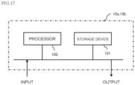
FIG. 17 is a circuit diagram showing hardware of a first CPU and a second CPU in embodiments.
MODE FOR CARRYING OUT THE INVENTION
Embodiment 1
Hereinafter, Embodiment 1 will be described on the basis of FIG. 1 to FIG. 8 . Then, in each of the drawings, identical or equivalent members and portions will be described with the same reference numerals (and letters) assigned thereto. FIG. 1 is a circuit diagram showing a wheel brake in a vehicle electric braking device according to Embodiment 1. FIG. 2 is a flow chart for explaining a method of controlling the wheel brake in the vehicle electric braking device according to Embodiment 1. FIG. 3 is a circuit diagram showing a state where the wheel brake is connected to a brake mechanism and a battery in the vehicle electric braking device according to Embodiment 1. FIG. 4 is a block diagram showing the vehicle electric braking device according to Embodiment 1. FIG. 5 is a block diagram showing other example of the vehicle electric braking device according to Embodiment 1. FIG. 6 is a block diagram showing other example of the vehicle electric braking device according to Embodiment 1. FIG. 7 is a circuit diagram showing other example of a state where a wheel brake is connected to a brake mechanism and batteries in the vehicle electric braking device according to Embodiment 1. FIG. 8 is a block diagram showing other example of the vehicle electric braking device according to Embodiment 1.
In FIG. 1 , a motor 2 is equipped with two sets of independent three phase coil windings, a first coil winding 2 a and a second coil winding 2 b, with respect to a single unit rotor (not shown in the drawing). A first control unit 1 a performs driving control of the first coil winding 2 a of the motor 2 and a second control unit 1 b performs driving control of the second coil winding 2 b of the motor 2, thereby operating a brake actuator. The first control unit 1 a includes: a first inverter circuit 3 a, a first control circuit section 4 a on which a first central processing unit (hereinafter, referred to as “first CPU”) 10 a is mounted, a first power source relay switching element 5 a that forms a first power source relay circuit, and the like. The second control unit 1 b includes: a second inverter circuit 3 b, a second control circuit section 4 b on which a second central processing unit (hereinafter, referred to as “second CPU”) 10 b is mounted, a second power source relay switching element 5 b that forms a second power source relay circuit, and the like.
Furthermore, through an ignition switch 7 from a battery 9 serving as a power source mounted on the vehicle, the power source is fed to the first control circuit section 4 a via a first power source circuit 13 a and the power source is fed to the second control circuit section 4 b via a second power source circuit 13 b.
Moreover, information such as a load sensor which is mounted in the vicinity of the brake actuator and detects pressing force of the brake actuator, a speed sensor that detects vehicle running speed, and the like is inputted from a sensor 8 to the first control circuit section 4 a and the second control circuit section 4 b. Incidentally, a large number of terminals, 17 a, 17 b, 17 c, which are for connecting to external devices are provided on the first control unit 1 a and the second control unit 1 b and, specifically, such terminals are arranged by fixing connectors to circuit boards.
The information from the sensor 8 is transmitted to the first CPU 10 a via a first input circuit 12 a of the first control circuit section 4 a and to the second CPU 10 b via a second input circuit 12 b of the second control circuit section 4 b. The first CPU 10 a calculates a current value which is for rotating the motor 2 on the basis of the inputted information and outputs a control signal to a first output circuit 11 a; and the second CPU 10 b calculates a current value which is for rotating the motor 2 on the basis of the inputted information and outputs a control signal to a second output circuit 11 b. The first output circuit 11 a receives an input signal and outputs a control signal that controls the respective switching elements of the first inverter circuit 3 a that constitutes an output circuit; and the second output circuit 11 b receives an input signal and outputs a control signal that controls the respective switching elements of the second inverter circuit 3 b that constitutes an output circuit.
Incidentally, since only a small current flows in the first output circuit 11 a and the second output circuit 11 b, the first output circuit 11 a is arranged in the first control circuit section 4 a and the second output circuit 11 b is arranged in the second control circuit section 4 b; however, the first output circuit 11 a may be arranged in the first inverter circuit 3 a and the second output circuit 11 b may be arranged in the second inverter circuit 3 b.
Furthermore, a configuration is made such that the first inverter circuit 3 a and the second inverter circuit 3 b have the same circuit configuration with respect to respective phases (U1, V1, W1) of the first coil winding 2 a of the motor 2 and respective phases (U2, V2, W2) of the second coil winding 2 b of the motor 2 and current is independently supplied to the respective phases of the first coil winding 2 a and the respective phases of the second coil winding 2 b.
The first inverter circuit 3 a is provided with: first upper arm switching elements (31U1, 31V1, 31W1) and first lower arm switching elements (32U1, 32V1, 32W1), which supply an output current to the three phase first coil winding 2 a (U1, V1, W1) of the motor 2; first motor relay switching elements 34U1, 34V1, 34W1 which are connected to or disconnected from wiring with the respective phases U1, V1, W1 of the first coil winding 2 a of the motor 2; first shunt resistors 33U1, 33V1, 33W1 for current detection; and first noise suppression capacitors 30U1, 30V1, 30W1.
The second inverter circuit 3 b is provided with: second upper arm switching elements (31U2, 31V2, 31W2) and second lower arm switching elements (32U2, 32V2, 32W2), which supply an output current to the three phase second coil winding 2 b (U2, V2, W2) of the motor 2; second motor relay switching elements 34U2, 34V2, 34W2 which are connected to or disconnected from wiring with the respective phases U2, V2, W2 of the second coil winding 2 b of the motor 2; second shunt resistors 33U2, 33V2, 33W2 for current detection; and second noise suppression capacitors 30U2, 30V2, 30W2.
Furthermore, a potential difference across terminals of the first shunt resistors 33U1, 33V1, 33W1 and, for example, a terminal voltage of the first coil winding 2 a of the motor 2 are also inputted to the first input circuit 12 a; and a potential difference across terminals of the second shunt resistors 33U2, 33V2, 33W2 and, for example, a terminal voltage of the second coil winding 2 b of the motor 2 are also inputted to the second input circuit 12 b. A configuration is made such that these kinds of information are also inputted to the first CPU 10 a and the second CPU 10 b, a difference from a detected value corresponding to a calculated current value is calculated, and a so-called feedback control is performed, whereby a necessary motor current is supplied to drive the brake actuator.
Incidentally, a control signal of the first power source relay switching element 5 a is also outputted and current supply to the first coil winding 2 a of the motor 2 can be interrupted by the first power source relay switching element 5 a; and a control signal of the second power source relay switching element 5 b is also outputted and current supply to the second coil winding 2 b of the motor 2 can be interrupted by the second power source relay switching element 5 b. In the same way, the first motor relay switching elements 34U1, 34V1, 34W1 can also independently interrupt current supply to the first coil winding 2 a of the motor 2; and the second motor relay switching elements 34U2, 34V2, 34W2 can also independently interrupt current supply to the second coil winding 2 b of the motor 2.
Here, a first filter 6 a constituted of a capacitor and a coil is connected to power source terminals (+B, GND) of the battery 9 to suppress noise emission due to pulse width modulation of the first inverter circuit 3 a; and a second filter 6 b constituted of a capacitor and a coil is connected to the power source terminals (+B, GND) of the battery 9 to suppress noise emission due to pulse width modulation of the second inverter circuit 3 b. Furthermore, since heat is generated by a large current that flows in the first power source relay switching element 5 a and the second power source relay switching element 5 b, a configuration may be such that the first power source relay switching element 5 a is incorporated in the first inverter circuit 3 a so as to be coupled to a heat dissipation body of the first inverter circuit 3 a and the second power source relay switching element 5 b is incorporated in the second inverter circuit 3 b so as to be coupled to a heat dissipation body of the second inverter circuit 3 b, whereby the heat is dissipated.
By the way, the first CPU 10 a is equipped with an abnormality detection means that detects an abnormality of the first inverter circuit 3 a, the first coil winding 2 a (U1, V1, W1) of the motor 2, and the like from the inputted various kinds of information; and the second CPU 10 b is equipped with an abnormality detection means that detects an abnormality of the second inverter circuit 3 b, the second coil winding 2 b (U2, V2, W2) of the motor 2, and the like from the inputted various kinds of information. Then, when an abnormality is detected, the first power source relay switching element 5 a or the second power source relay switching element 5 b is turned OFF and the battery 9 is cut OFF according to the abnormality. Alternatively, only a predetermined phase of the first motor relay switching elements 34U1, 34V1, 34W1 and the second motor relay switching elements 34U2, 34V2, 34W2 is turned OFF and the current supply can be interrupted. Moreover, a configuration is made such that when an abnormality is detected, the first CPU 10 a and the second CPU 10 b feed power to a notification device 15 such as a lamp via the first driving circuit 16 a and the second driving circuit 16 b, respectively, thereby activating the notification device 15.
Meanwhile, the motor 2 is a brushless motor in which two sets of three phase coil windings, the first coil winding 2 a and the second coil winding 2 b, are each star-connected and on which a first rotation sensor 19 a and a second rotation sensor 19 b which are for detecting the rotation position of the rotor are mounted. Two sets of sensors (not shown in the drawing) are mounted on each of the first rotation sensor 19 a and the second rotation sensor 19 b in order to secure each redundant system; and rotation information of the rotor is transmitted to each of the first input circuit 12 a of the first control circuit section 4 a and the second input circuit 12 b of the second control circuit section 4 b.
Incidentally, the motor 2 may be a delta-connected brushless motor or two bipolar pairs of brushed motors rather than the three-phase star-connected brushless motor. Furthermore, specifications of coil winding may be a distributed winding or a concentrated winding. However, it is necessary to configure so that the desired number of rotation of the motor and torque can be outputted even only one set of coil windings or two sets of coil windings.
As an example, as shown in FIG. 3 , the motor 2 that constitutes a wheel brake 50 is connected to a brake mechanism 40 and has a role to brake the vehicle. Specifically, a configuration is made such that material subjected to friction (not shown in the drawing) rotated together with wheels (not shown in the drawing) mounted on the vehicle and friction material (not shown in the drawing) which moves by power of the motor 2 are equipped and vehicle braking force is obtained by pressing the friction material to the material subjected to friction.
As described above, the first control unit 1 a and the second control unit 1 b which constitute the wheel brake 50 are configured so as to be able to independently drive the motor 2 by independently using input information, calculated values, and detected values.
Furthermore, a communication line 14 is connected between the first CPU 10 a and the second CPU 10 b so as to be able to transfer data and information. Each of operation states of the counterpart first CPU 10 a and the second CPU 10 b can be grasped by transferring the information by means of the communication line 14. For example, matters in which the first CPU 10 a detects an abnormality and turns OFF a predetermined switching element can be transmitted to the second CPU 10 b. If an abnormality occurs in the first CPU 10 a itself or the second CPU 10 b itself, a regular communication signal by a predetermined format cannot be transferred, whereby one side CPU can also grasp the occurrence of an abnormality of the other side CPU.
Next, a control method in the above circuit configuration and motor construction will be described.
Since control of each circuit is almost processed in accordance with a program of the first CPU 10 a or that of the second CPU 10 b, a description will be given according to a flow chart shown in FIG. 2 . Incidentally, the first CPU 10 a and the second CPU 10 b perform substantially the same process. First, a description will be given on one side first CPU 10 a.
First, when the ignition switch 7 is switched, a current is supplied to the first CPU 10 a through the first power source circuit 13 a and the process is started.
In Step S1, a random access memory (RAM), a read only memory (ROM), a port, and the like are initialized. Next, in Step S2, all kinds of information inputted via the first input circuit 12 a are acquired and stored. Communication data of a counterpart second CPU 10 b is also included in this information.
In Step S3, the presence or absence of abnormality detection in the counterpart second CPU 10 b is checked. The presence or absence of the counterpart abnormality can be determined by deciphering communication data with the counterpart second CPU 10 b. When no abnormality occurs (N:No) in the counterpart second CPU 10 b, the presence or absence of an abnormality in a self first CPU 10 a is checked in Step S4. Here, when an abnormality is not detected (N), the process is advanced to Step S5 and a normal control amount 1 in which no abnormality occurs in both of the first CPU 10 a and the second CPU 10 b is calculated.
Meanwhile, in Step S3, when an abnormality occurs (Y: Yes) in the counterpart second CPU 10 b, the process is advanced to Step S6 and the presence or absence of an abnormality in the self first CPU 10 a is checked in the same way as in Step S4. Here, when an abnormality occurs (Y) in the self first CPU 10 a, the process is advanced to Step S11 and processing at the time of self abnormality is performed. When there is no abnormality (N) in the self first CPU 10 a, the process is advanced to Step S7 and control amounts 2 under a condition of abnormality of the counterpart second CPU 10 b and a condition of normality of the self first CPU 10 a are calculated. Subsequently, the process is advanced to Step S8.
Next, in Step S4 or Step S6, when it is determined that an abnormality occurs in the first CPU 10 a itself, the process is advanced to Step S11 and a control signal is outputted so as to stop output to the first output circuit 11 a. Incidentally, the control signal may be classified into a plurality of levels on the basis of the occurred abnormality. For example, in the case of a ground short or a voltage short of the coil windings 2 a, 2 b, or the switching elements of the first inverter circuit 3 a and the second inverter circuit 3 b, a control signal is outputted so as to turn OFF all the switching elements including the first power source relay switching element 5 a.
Furthermore, when an open circuit failure occurs in one of the first upper arm switching elements (31U1, 31V1, 31W1) and the first lower arm switching elements (32U1, 32V1, 32W1) of the first inverter circuit 3 a, or in the first motor relay switching elements 34U1, 34V1, 34W1, it is also possible to stop driving of the switching element of only a phase where the abnormality occurs and to output a control command to the other phases as normal. Alternatively, when an open circuit failure occurs in one of the second upper arm switching elements (31U2, 31V2, 31W2) and the second lower arm switching elements (32U2, 32V2, 32W2) of the second inverter circuit 3 b, or in the second motor relay switching elements 34U2, 34V2, 34W2, it is also possible to stop driving of the switching element of only a phase where the abnormality occurs and to output a control command to the other phases as normal. Because of this, in Step S11, a setting can be performed so that a part of control can be processed continuously except for processing at the time of abnormality where all the phases are in a stopped state. Incidentally, when two-phase driving can be performed as described above, calculation processing of the control amount is also necessary and thus it may be more efficient to be processed in Steps S5, S7.
Next, in Step S12, data in an abnormal state is transmitted by means of the communication line 14. This data is transmitted, also including an abnormality level, for example, matters that all the switching elements are in an OFF state. Furthermore, in a state where only a certain phase is turned OFF, transmission can be made, also including ratio or the like in which a control amount in this case is compared to that in normal time; however, communication of this kind of abnormality contents can also be processed through Step S9 and Step S10. This allows the counterpart second CPU 10 b to grasp even the abnormality contents. Consequently, a control amount of the self first CPU 10 a can be corrected and outputted according to the abnormality of the counterpart second CPU 10 b.
Next, in Step S5, a description will be given on a method of calculating a control amount in normal time when no abnormality occurs in both of the first control unit 1 a and the second control unit 1 b.
In Step S5, a current value required according to conditions of required pressing force, vehicle speed, or the like is calculated and this is divided into one half. This halved current value is the control amount allocated to one side control unit. Moreover, a current being supplied at present is detected from a potential difference across each of the first shunt resistors 33U1, 33V1, 33W1 and is outputted as a control command value according to the difference between a target value and the detected value.
Meanwhile, in Step S7, an abnormality occurs in the counterpart system; thus, a current value required for only the self system needs to be calculated and supplied as the control amount 2. Alternatively, if only one-phase is abnormal and two-phase driving is performed in the counterpart system, a calculation is made so as to supply two-thirds the current value, and a control command value thus calculated is outputted. Furthermore, when the counterpart system is in a state where the motor cannot be driven at all, all the calculated control amount is controlled so as to output in the self system. Moreover, when an abnormality occurs in only on phase as previously described, a control amount for two-phase driving can be calculated in Step S5 or Step S7. More specifically, the control amount can be calculated by calculating in almost the same procedure as that in normal time and, finally, by correcting for two-phase driving. Additionally, the process can be executed in the same procedure by changing only a distribution rate in the first CPU 10 a and the second CPU 10 b, whereby simplification of control logic can be achieved.
Next, in Step S8, a control command is outputted so as to be able to drive the respective switching elements on the basis of the control command value. The upper and lower arm switching elements of the first inverter circuit 3 a and the second inverter circuit 3 b are pulse-width modulated and thus their corresponding control signals are outputted.
In Step S9, the presence or absence of an abnormality is checked. Specifically, an abnormality can be detected by a method in which current flowing to drive each switching element is detected by the first shunt resistors 33U1, 33V1, 33W1 and the second shunt resistors 33U2, 33V2, 33W2, and by monitoring a coil winding terminal voltage of the motor and distinguishing that a predetermined voltage appears according to the driving of the switching elements.
Moreover, when a difference from the detected current value with respect to the target current value does not come close even after a predetermined time elapses, there is a possibility of a leak and thus it can also be determined as an abnormality.
As described above, voltage and current of each portion are monitored to detect an abnormality, whereby an abnormality can be detected even in only one phase.
When the first CPU 10 a detects this kind of abnormality, the first CPU 10 a stores, also including an abnormal state and communicates the abnormal state to the counterpart second CPU 10 b via the communication line 14 in Step S10. If there is other necessary information, it is efficient when such kind of information is transmitted being included in this process. For example, the accuracy of calculation of each other's control amount can also be checked by transferring information of the first input circuit 12 a and information of the control amount.
Next, in Step S13, the process waits until a predetermined time, for example, 5 msec elapses, and if the predetermined time elapses (Y), the process is returned to Step S2 and the process is advanced by repeating in the same procedure again.
Although a description will be omitted, the above-described processing operation of the first CPU 10 a is also executed by the second CPU 10 b in the same way, thereby forming a double redundant system.
Next, a description will be made on the second CPU 10 b. First, when an ignition switch 7 is switched, a current is supplied to the second CPU 10 b through the second power source circuit 13 b and the process is started.
In Step S1, a RAM, a ROM, a port, and the like are initialized. Next, in Step S2, all kinds of information inputted via the second input circuit 12 b are acquired and stored. Communication data of a counterpart first CPU 10 a is also included in this information.
In Step S3, the presence or absence of abnormality detection in the counterpart first CPU 10 a is checked. The presence or absence of the counterpart abnormality can be determined by deciphering communication data with the counterpart first CPU 10 a. When no abnormality occurs (N:No) in the counterpart first CPU 10 a, the presence or absence of an abnormality in a self second CPU 10 b is checked in Step S4. Here, when an abnormality is not detected (N), the process is advanced to Step S5 and a normal control amount 1 in which no abnormality occurs in both of the first CPU 10 a and the second CPU 10 b is calculated.
Meanwhile, in Step S3, when an abnormality occurs (Y:Yes) in the counterpart first CPU 10 a, the process is advanced to Step
S6 and the presence or absence of an abnormality in the self second CPU 10 b is checked in the same way as in Step S4. Here, when an abnormality occurs (Y) in the self second CPU 10 b, the process is advanced to Step S11 and processing at the time of self abnormality is performed. When there is no abnormality (N) in the self second CPU 10 b, the process is advanced to Step S7 and control amounts 2 under a condition of abnormality of the counterpart first CPU 10 a and a condition of normality of the self second CPU 10 b are calculated. Subsequently, the process is advanced to Step S8.
Next, in Step S4 or Step S6, when it is determined that an abnormality occurs in the second CPU 10 b itself, the process is advanced to Step S11 and a control signal is outputted so as to stop output to the second output circuit 11 b. Incidentally, the control signal may be classified into a plurality of levels on the basis of the occurred abnormality. For example, in the case of a ground short or a voltage short of the first coil winding 2 a and the second coil winding 2 b, or the switching elements of the first inverter circuit 3 a and the second inverter circuit 3 b, a control signal is outputted so as to turn OFF all the switching elements including the second power source relay switching element b.
Furthermore, when an open circuit failure occurs in one of the second upper arm switching elements (31U2, 31V2, 31W2) and the second lower arm switching elements (32U2, 32V2, 32W2) of the second inverter circuit 3 b, or in the second motor relay switching elements 34U2, 34V2, 34W2, it is also possible to stop driving of the switching element of only a phase where the abnormality occurs and to output a control command to the other phases as normal. Alternatively, when an open circuit failure occurs in one of the first upper arm switching elements (31U1, 31V1, 31W1) and the first lower arm switching elements (32U1, 32V1, 32W1) of the first inverter circuit 3 a, or in the first motor relay switching elements 34U1, 34V1, 34W1, it is also possible to stop driving of the switching element of only a phase where the abnormality occurs and to output a control command to the other phases as normal. Because of this, in Step S11, a setting can be performed so that a part of control can be processed continuously except for processing at the time of abnormality where all the phases are in a stopped state. Incidentally, when two-phase driving can be performed as described above, calculation processing of the control amount is also necessary and thus it may be more efficient to be processed in Steps S5, S7.
Next, in Step S12, data in an abnormal state is transmitted by means of the communication line 14. This data is transmitted, also including an abnormality level, for example, matters that all the switching elements are in an OFF state. Furthermore, in a state where only a certain phase is turned OFF, transmission can be made, also including ratio or the like in which a control amount in this case is compared to that in normal time; however, communication of this kind of abnormality contents can also be processed through Step S9 and Step S10. This allows the counterpart first CPU 10 a to grasp even the abnormality contents. Consequently, a control amount of the self second CPU 10 b can be corrected and outputted according to the abnormality of the counterpart first CPU 10 a.
Next, in Step S5, a description will be given on a method of calculating a control amount in normal time when no abnormality occurs in both of the first control unit 1 a and the second control unit 1 b.
In Step S5, a current value required according to conditions of required pressing force, vehicle speed, or the like is calculated and this is divided into one half. This halved current value is the control amount allocated to one side control unit. Moreover, a current being supplied at present is detected from a potential difference across each of the second shunt resistors 33U2, 33V2, 33W2 and is outputted as a control command value according to the difference between a target value and the detected value.
Meanwhile, in Step S7, an abnormality occurs in the counterpart system; thus, a current value required for only the self system needs to be calculated and supplied as the control amount 2. Alternatively, if only one-phase is abnormal and two-phase driving is performed in the counterpart system, a calculation is made so as to supply two-thirds the current value, and a control command value thus calculated is outputted. Furthermore, when the counterpart system is in a state where the motor cannot be driven at all, all the calculated control amount is controlled so as to output in the self system. Moreover, when an abnormality occurs in only on phase as previously described, a control amount for two-phase driving can be calculated in Step S5 or Step S7. More specifically, the control amount can be calculated by calculating in almost the same procedure as that in normal time and, finally, by correcting for two-phase driving. Additionally, the process can be executed in the same procedure by changing only a distribution rate in the first CPU 10 a and the second CPU 10 b, whereby simplification of control logic can be achieved.
Next, in Step S8, a control command is outputted so as to be able to drive the respective switching elements on the basis of the control command value. The upper and lower arm switching elements of the first inverter circuit 3 a and the second inverter circuit 3 b are pulse-width modulated and thus their corresponding control signals are outputted.
In Step S9, the presence or absence of an abnormality is checked. Specifically, an abnormality can be detected by a method in which current flowing to drive each switching element is detected by the first shunt resistors 33U1, 33V1, 33W1 and the second shunt resistors 33U2, 33V2, 33W2, and by monitoring a coil winding terminal voltage of the motor and distinguishing that a predetermined voltage appears according to the driving of the switching elements.
Moreover, when a difference from the detected current value with respect to the target current value does not come close even after a predetermined time elapses, there is a possibility of a leak and thus it can also be determined as an abnormality.
As described above, voltage and current of each portion are monitored to detect an abnormality, whereby an abnormality can be detected even in only one phase.
When the second CPU 10 b detects this kind of abnormality, the second CPU 10 b stores, also including an abnormal state and communicates the abnormal state to the counterpart first CPU 10 a via the communication line 14 in Step S10. If there is other necessary information, it is efficient when such kind of information is transmitted being included in this process. For example, the accuracy of calculation of each other's control amount can also be checked by transferring information of the second input circuit 12 b and information of the control amount.
Next, in Step S13, the process waits until a predetermined time, for example, 5 msec elapses, and if the predetermined time elapses (Y), the process is returned to Step S2 and the process is advanced by repeating in the same procedure again.
Consequently, in a normal state where there is no abnormality, each control unit is allocated one-half each and performs control of the motor 2; however, when an abnormality occurs in one side control unit, a power source relay connected to its system is turned OFF and a power source relay connected to a normal system is kept ON. Then, even in a worst case, a normal CPU can continue 100% control and does not fall into a situation where driving of a brake actuator becomes difficult.
Furthermore, there can be appended a function that notifies abnormality of not only the self system but also the counterpart system, notification to a driver in the occurrence of abnormality is assured, and the driver can also be informed of which side of the motor 2 is abnormal. This notification can be achieved by actuating the notification device 15 in Step S10 or Step S12 on the basis of output at the time of abnormality in Step S9 or Step S11.
Furthermore, even in normal time when no abnormality occurs, for example, when the temperature of one side control unit is higher than that of the other side control unit, uneven control such as one-third to two-thirds can also be performed. This kind of situation is enabled by transmitting information in which one side control unit asks for help to the other side control unit via the communication line 14 and notifying the counterpart control unit of the information. Moreover, when the self control unit is also exposed to a high temperature, both of the control units are in a high load state; thus, the occurrence of a failure can also be prevented by mutually reducing the target value.
Additionally, the sharing ratio of the control amount can be theoretically changed in any way; however, the ratio having only two or three stages is advantageous in light of simplification of control specifications, simplification of CPU programs, and measures at the time of abnormality of the CPU itself. For example, there can also be three-stages of level, with the normal side being 50%, 65%, 100%, and the abnormal side being 50%, 35%, 0%.
Incidentally, in the aforementioned embodiment, although Communication 1 in Step S10 and Communication 2 in Step S12 are independently provided in two places, this is because output systems are independently provided taking into consideration matters that an abnormality occurs; and Communication 1 and Communication 2 may be integrated into one place. Furthermore, an abnormality detection means of Step S9 is arranged after output Step S8; however, the abnormality detection means may be provided between, for example, Step S2 and Step S3.
Taking into consideration a case where, in particular, the switching elements in the first control unit 1 a and the second control unit 1 b are driven at 100%, their heat dissipation properties need to be sufficiently secured. Specifically, it is necessary to design taking into consideration a current capacity of the element itself and a heat sink structure for heat dissipation. Furthermore, also with regard to the motor 2, it is necessary to design specifications of coils and magnets and the scale of each component so that maximum torque with respect to the desired number of rotation can be outputted by only one set of three phase coil windings.
Furthermore, when one side control unit becomes abnormal and if a heat sink (not shown in the drawing) is a single unit, the entire heat sink can be used by only one system; thus, heat dissipation properties can be improved. Moreover, heat bias can be eliminated to form even heat distribution by this single unit heat sink (not shown in the drawing).
Moreover, various types of sensors are suitably mountable and are not limited to the sensor described in this embodiment. For example, it is not objectionable even if the first shunt resistor and the second shunt resistor are non-contact current sensors. Besides, the connector, the motor relay, the noise suppression capacitor, the filter, and the like are mounted; however, these may not be mounted or may be mounted by changing their configuration and similar effects can be obtained.
The wheel brake 50 shown in FIG. 3 is a piece of apparatus which brakes at least one of the wheels mounted on the vehicle. The vehicle electric braking device in Embodiment 1 of the present application is constituted of the combination of the battery 9, the brake mechanism 40, and the wheel brake 50 and is mounted on the vehicle.
The wheel brake 50 is constituted of: the motor 2 equipped with two sets of independent three phase coil windings, the first coil winding 2 a and the second coil winding 2 b, with respect to the single unit rotor (not shown in the drawing); the first control unit 1 a which is connected to the first coil winding 2 a of the motor 2 and controls the first coil winding 2 a of the motor 2; and the second control unit 1 b which is connected to the second coil winding 2 b of the motor 2 and controls the second coil winding 2 b of the motor 2. There is shown a case where the number of battery 9 serving as the power source is one and the battery 9 is connected to the first control unit 1 a and the second control unit 1 b; and the motor 2 is connected to the brake mechanism 40.
The first inverter circuit 3 a of the first control unit 1 a has three phase circuit configuration with respect to the respective phases (U1, V1, W1) of the first coil winding 2 a of the motor 2 and is configured so as to independently supply a current to each phase of the first coil winding 2 a. The second inverter circuit 3 b of the second control unit 1 b has three phase circuit configuration with respect to the respective phases (U2, V2, W2) of the second coil winding 2 b of the motor 2 and is configured so as to independently supply a current to each phase of the second coil winding 2 b.
Examples of the vehicle electric braking device in Embodiment 1 of the present application will be shown in FIG. 4 to FIG. 6 . Reference numeral 60 denotes a vehicle in which four wheels 41 a, 41 b, 41 c, 41 d are mounted. Brake mechanisms 40 a, 40 b, 40 c, 40 d are mounted on the wheels 41 a, 41 b, 41 c, 41 d, respectively. Although details of the brake mechanisms 40 a, 40 b, 40 c, 40 d are not shown, the brake mechanism is not a mechanism related to electric braking that is a feature of the present application, but is a conventional hydraulic brake mechanism and drawing and description thereof will be omitted. Reference numerals 50 a, 50 b, 50 c, 50 d denote wheel brakes and are each connected to the battery 9.
A description will be given on the arrangement of the wheel brakes 50 a to 50 d. A configuration is made such that, in the example of FIG. 4 , there is shown a case where the wheel brakes 50 a, 50 b are connected to two wheels on the front side 41 a, 41 b, respectively; in the example of FIG. 5 , there is shown a case where the wheel brakes 50 c, 50 d are connected to two wheels on the rear side 41 c, 41 d, respectively; and in the example of FIG. 6 , the wheel brakes 50 a, 50 b are connected to two wheels on the front side 41 a, 41 b, respectively, and the wheel brakes 50 c, 50 d are connected to two wheels on the rear side 41 c, 4 d, respectively, the wheel brakes 50 a, 50 b, 50 c, 50 d being connected to one battery 9.
The wheel brakes are mounted on a plurality of wheels, whereby the vehicle can be safely stopped, also in the occurrence of a failure. As an example, it is conceivable that a redundant wheel brake of the present application is connected to each of two wheels of four wheels and a wheel brake that is not made redundant, which is constituted of a three phase inverter and a three phase motor, is connected to each of the other two wheels. The vehicle can be safely stopped, also in the occurrence of a failure, by combining braking force in four wheels.
The wheel brake 50 shown in FIG. 7 shows a case where the number of batteries serving as a power source is two and shows a case where a first control unit 1 a is connected to a first battery 9 a and a second control unit 1 b is connected to a second battery 9 b. A configuration is made such that power is fed from the first battery 9 a to the first control unit 1 a and power is fed from the second battery 9 b to the second control unit 1 b. Not only the control unit but also the battery serving as the power source are made redundant, whereby safeness in the occurrence of a failure is further improved. FIG. 8 shows other example in which the wheel brakes 50 a, 50 b are mounted on the vehicle 60.
Here, although the power source is the battery, it may be configured such that this is a generator, or a DC/DC converter, or the combination thereof. If the power source is made redundant, similar effects can be obtained. In FIG. 8 , the wheel brakes 50 a, 50 b are connected to two wheels on the front side 41 a, 41 b, respectively; however, it may be configured such that the wheel brakes 50 c, 50 d are mounted on two wheels on the rear side 41 c, 41 d, respectively; or the wheel brakes 50 a, 50 b are connected to two wheels on the front side 41 a, 41 b, respectively, and the wheel brakes 50 c, 50 d are connected to two wheels on the rear side 41 c, 41 d, respectively. The wheel brakes are mounted on a plurality of wheels, whereby the vehicle can be safely stopped, also in the occurrence of a failure.
Embodiment 2
Embodiment 2 will be described on the basis of FIG. 9 to FIG. 13 . Then, in each of the drawings, identical or equivalent members and portions will be described with the same reference numerals (and letters) assigned thereto. FIG. 9 is a circuit diagram showing a state where a wheel brake is connected to a brake mechanism and batteries in a vehicle electric braking device according to Embodiment 2. FIG. 10 is a block diagram showing the vehicle electric braking device according to Embodiment 2. FIG. 11 is a circuit diagram showing the wheel brake in the vehicle electric braking device according to Embodiment 2. FIG. 12 is a circuit diagram showing other example of a state where a wheel brake is connected to a brake mechanism and batteries in the vehicle electric braking device according to Embodiment 2. FIG. 13 is a block diagram showing other example of the vehicle electric braking device according to Embodiment 2.
FIG. 11 is the circuit diagram showing an electric relevant part configuration of the wheel brake in the vehicle electric braking device. The circuit diagram is configured such that, in the configuration of FIG. 1 described in Embodiment 1, the battery 9 serving as the power source is changed to a battery 9 a, a battery 9 b, and a battery 9 c; a third power source relay switching element 5 c, which forms a third power source relay circuit between the battery 9 c and the first inverter circuit 3 a, is connected in parallel to the first power source relay switching element 5 a; and a fourth power source relay switching element 5 d, which forms a fourth power source relay circuit between the battery 9 c and the second inverter circuit 3 b, is connected in parallel to the second power source relay switching element 5 b. Since other constituent components are similar to those described in FIG. 1 and the operation as the wheel brake is similar to those described in FIG. 2 , the description thereof will be omitted.
A wheel brake 50 shown in FIG. 9 shows a case where a first control unit 1 a is connected to the first battery 9 a and the third battery 9 c; and a second control unit 1 b is connected to the second battery 9 b and the third battery 9 c. A configuration is made such that power is fed from the first battery 9 a or the third battery 9 c to the first control unit 1 a and power is fed from the second battery 9 b or the third battery 9 c to the second control unit 1 b. FIG. 10 shows other example of mounting on a vehicle and the aforementioned effects can be obtained.
Furthermore, a wheel brake 50 shown in FIG. 12 shows a case where a first control unit 1 a is connected to the first battery 9 a and the third battery 9 c and a second control unit 1 b is connected to the second battery 9 b and a fourth battery 9 d. A configuration is made such that power is fed from the first battery 9 a or the third battery 9 c to the first control unit 1 a and power is fed from the second battery 9 b or the fourth battery 9 d to the second control unit 1 b. FIG. 13 shows other example of mounting on a vehicle and the aforementioned effects can be obtained.
Here, although the power source is the battery, it may be configured such that this is a generator, or a DC/DC converter, or the combination thereof. If the power source is made redundant, similar effects can be obtained. In FIG. 10 and FIG. 13 , the wheel brakes are connected to two wheels on the front side; however, it may be configured such that the wheel brakes are mounted on two wheels on the rear side; or the wheel brakes are connected to two wheels on the front side and the wheel brakes are connected to two wheels on the rear side. The wheel brakes are mounted on a plurality of wheels, whereby the vehicle can be safely stopped, also in the occurrence of a failure.
Moreover, a feature of Embodiment 2 is a method of controlling the first power source relay switching element 5 a, the second power source relay switching element 5 b, the third power source relay switching element 5 c, and the fourth power source relay switching element 5 d in the case where multiple power sources are connected to the wheel brakes. The reason why the multiple power sources are connected to the wheel brakes is to obtain vehicle braking force even when the power source has a failure. In the case of such a configuration, not only the wheel brakes but also other auxiliary machines (although not shown in the drawing, various types of engine control units (ECUs), headlights, a navigation system, and the like) are connected to the respective power sources; and accordingly, there is a concern that other auxiliary sources also fail in linkage when the wheel brakes fail. In order to obtain vehicle braking force continuously while preventing such a failure, it becomes important to control the first power source relay switching element 5 a, the second power source relay switching element 5 b, the third power source relay switching element 5 c, and the fourth power source relay switching element 5 d.
Embodiment 3
Embodiment 3 will be described on the basis of FIG. 14 . FIG. 14 is a control table for explaining a method of controlling a wheel brake in a vehicle electric braking device according to Embodiment 3. FIG. 14 shows a method of controlling a first power source relay switching element 5 a, a second power source relay switching element 5 b, a third power source relay switching element 5 c, and a fourth power source relay switching element 5 d.
When there is no failure place in a wheel brake 50, the first power source relay switching element 5 a and the second power source relay switching element 5 b are turned OFF, the third power source relay switching element 5 c and the fourth power source relay switching element 5 d are turned ON, and power is fed from a battery 9 c to a first inverter circuit 3 a of a first control unit 1 a and a second inverter circuit 3 b of a second control unit 1 b. Then, driving indication of turning ON is outputted to the first inverter circuit 3 a of the first control unit 1 a and driving indication of turning ON is outputted to the second inverter circuit 3 b of the second control unit 1 b.
When a failure occurs in the first inverter circuit 3 a of the first control unit 1 a, the operation thereof is performed such that the first power source relay switching element 5 a, the second power source relay switching element 5 b, and the third power source relay switching element 5 c are turned OFF, the fourth power source relay switching element 5 d is kept ON continuously, driving indication to the first inverter circuit 3 a of the first control unit 1 a is turned OFF, and driving indication to the second inverter circuit 3 b of the second control unit 1 b is kept ON continuously. It is possible to suppress an influence on other auxiliary machine by disconnecting a failed system from the battery and to obtain vehicle braking force continuously by continuing the operation in a normal system.
When a failure occurs in the second inverter circuit 3 b of the second control unit 1 b, the operation thereof is performed such that the first power source relay switching element 5 a, the second power source relay switching element 5 b, and the fourth power source relay switching element 5 d are turned OFF, the third power source relay switching element 5 c is kept ON continuously, driving indication to the second inverter circuit 3 b of the second control unit 1 b is turned OFF, and driving indication to the first inverter circuit 3 a of the first control unit 1 a is kept ON continuously. It is possible to suppress an influence on other auxiliary machine by disconnecting a failed system from the battery and to obtain vehicle braking force continuously by continuing the operation in a normal system.
Also, when a failure occurs in a motor 2, the same effects can be obtained by performing the same operation as the case where a failure occurs in the first inverter circuit 3 a of the first control unit 1 a and the second inverter circuit 3 b of the second control unit 1 b. More specifically, when a failure occurs in the motor 2 on the first inverter circuit 3 a side of the first control unit 1 a, the operation thereof is performed such that the first power source relay switching element 5 a, the second power source relay switching element 5 b, and the third power source relay switching element 5 c are turned OFF, the fourth power source relay switching element 5 d is kept ON continuously, driving indication to the first inverter circuit 3 a of the first control unit 1 a is turned OFF, and driving indication to the second inverter circuit 3 b of the second control unit 1 b is kept ON continuously. It is possible to suppress an influence on other auxiliary machine by disconnecting a failed system from the battery and to obtain vehicle braking force continuously by continuing the operation in a normal system.
When a failure occurs in the motor 2 on the second inverter circuit 3 b side of the second control unit 1 b, the operation thereof is performed such that the first power source relay switching element 5 a, the second power source relay switching element 5 b, and the fourth power source relay switching element 5 d are turned OFF, the third power source relay switching element 5 c is kept ON continuously, driving indication to the second inverter circuit 3 b of the second control unit 1 b is turned OFF, and driving indication to the first inverter circuit 3 a of the first control unit 1 a is kept ON continuously. It is possible to suppress an influence on other auxiliary machine by disconnecting a failed system from the battery and to obtain vehicle braking force continuously by continuing the operation in a normal system.
Embodiment 4
Embodiment 4 will be described on the basis of FIG. 15 . FIG. 15 is a control table for explaining a method of controlling a wheel brake in a vehicle electric braking device according to Embodiment 4. FIG. 15 shows a method of controlling a first power source relay switching element 5 a, a second power source relay switching element 5 b, a third power source relay switching element 5 c, and a fourth power source relay switching element 5 d.
When there is no failure place in a wheel brake 50, the first power source relay switching element 5 a and the second power source relay switching element 5 b are turned ON, the third power source relay switching element 5 c and the fourth power source relay switching element 5 d are turned OFF, power is fed from a first battery 9 a to a first inverter circuit 3 a of a first control unit 1 a, and power is fed from a second battery 9 b to a second inverter circuit 3 b of a second control unit 1 b. Then, driving indication of turning ON is outputted to the first inverter circuit 3 a of the first control unit 1 a and driving indication of turning ON is outputted to the second inverter circuit 3 b of the second control unit 1 b.
When a failure occurs in the first inverter circuit 3 a of the first control unit 1 a, the operation thereof is performed such that the first power source relay switching element 5 a, the third power source relay switching element 5 c, and the fourth power source relay switching element 5 d are turned OFF, the second power source relay switching element 5 b is kept ON continuously, driving indication to the first inverter circuit 3 a of the first control unit 1 a is turned OFF, and driving indication to the second inverter circuit 3 b of the second control unit 1 b is kept ON continuously. It is possible to suppress an influence on other auxiliary machine by disconnecting a failed system from the battery and to obtain vehicle braking force continuously by continuing the operation in a normal system.
When a failure occurs in the second inverter circuit 3 b of the second control unit 1 b, the operation thereof is performed such that the second power source relay switching element 5 b, the third power source relay switching element 5 c, and the fourth power source relay switching element 5 d are turned OFF, the first power source relay switching element 5 a is kept ON continuously, driving indication to the second inverter circuit 3 b of the second control unit 1 b is turned OFF, and driving indication to the first inverter circuit 3 a of the first control unit 1 a is kept ON continuously. It is possible to suppress an influence on other auxiliary machine by disconnecting a failed system from the battery and to obtain vehicle braking force continuously by continuing the operation in a normal system.
Also, when a failure occurs in a motor 2, the same effects can be obtained by performing the same operation as the case where a failure occurs in the first inverter circuit 3 a of the first control unit 1 a and the second inverter circuit 3 b of the second control unit 1 b. More specifically, when a failure occurs in the motor 2 on the first inverter circuit 3 a side of the first control unit 1 a, the operation thereof is performed such that the first power source relay switching element 5 a, the third power source relay switching element 5 c, and the fourth power source relay switching element 5 d are turned OFF, the second power source relay switching element 5 b is kept ON continuously, driving indication to the first inverter circuit 3 a of the first control unit 1 a is turned OFF, and driving indication to the second inverter circuit 3 b of the second control unit 11 b is kept ON continuously. It is possible to suppress an influence on other auxiliary machine by disconnecting a failed system from the battery and to obtain vehicle braking force continuously by continuing the operation in a normal system.
When a failure occurs in the motor 2 on the second inverter circuit 3 b side of the second control unit 1 b, the operation thereof is performed such that the second power source relay switching element 5 b, the third power source relay switching element 5 c, and the fourth power source relay switching element 5 d are turned OFF, the first power source relay switching element 5 a is kept ON continuously, driving indication to the second inverter circuit 3 b of the second control unit 1 b is turned OFF, and driving indication to the first inverter circuit 3 a of the first control unit 1 a is kept ON continuously. It is possible to suppress an influence on other auxiliary machine by disconnecting a failed system from the battery and to obtain vehicle braking force continuously by continuing the operation in a normal system.
Embodiment 5
Embodiment 5 will be described on the basis of FIG. 16 . FIG. 16 is a control table for explaining a method of controlling a wheel brake in a vehicle electric braking device according to Embodiment 5. FIG. 16 shows a method of controlling a first power source relay switching element 5 a, a second power source relay switching element 5 b, a third power source relay switching element 5 c, and a fourth power source relay switching element 5 d.
When there is no failure place in a wheel brake 50, all the first power source relay switching element 5 a, the second power source relay switching element 5 b, the third power source relay switching element 5 c, and the fourth power source relay switching element 5 d are turned ON, power is fed from a first battery 9 a and a third battery 9 c to a first inverter circuit 3 a of a first control unit 1 a, and power is fed from a second battery 9 b and a third battery 9 c to a second inverter circuit 3 b of a second control unit 1 b. Then, driving indication of turning ON is outputted to the first inverter circuit 3 a of the first control unit 1 a and driving indication of turning ON is outputted to the second inverter circuit 3 b of the second control unit 1 b.
When a failure occurs in the first inverter circuit 3 a of the first control unit 1 a, the operation thereof is performed such that the first power source relay switching element 5 a and the third power source relay switching element 5 c are turned OFF, the second power source relay switching element 5 b and the fourth power source relay switching element 5 d are kept ON continuously, driving indication to the first inverter circuit 3 a of the first control unit 1 a is turned OFF, and driving indication to the second inverter circuit 3 b of the second control unit 1 b is kept ON continuously. It is possible to suppress an influence on other auxiliary machine by disconnecting a failed system from the battery and to obtain vehicle braking force continuously by continuing the operation in a normal system.
When a failure occurs in the second inverter circuit 3 b of the second control unit 1 b, the operation thereof is performed such that the second power source relay switching element 5 b and the fourth power source relay switching element 5 d are turned OFF, the first power source relay switching element 5 a and the third power source relay switching element 5 c are kept ON continuously, driving indication to the second inverter circuit 3 b of the second control unit 1 b is turned OFF, and driving indication to the first inverter circuit 3 a of the first control unit 1 a is kept ON continuously. It is possible to suppress an influence on other auxiliary machine by disconnecting a failed system from the battery and to obtain vehicle braking force continuously by continuing the operation in a normal system.
Also, when a failure occurs in a motor 2, the same effects can be obtained by performing the same operation as the case where a failure occurs in the first inverter circuit 3 a of the first control unit 1 a and the second inverter circuit 3 b of the second control unit 1 b. More specifically, when a failure occurs in the motor 2 on the first inverter circuit 3 a side of the first control unit 1 a, the operation thereof is performed such that the first power source relay switching element 5 a and the third power source relay switching element 5 c are turned OFF, the second power source relay switching element 5 b and the fourth power source relay switching element 5 d are kept ON continuously, driving indication to the first inverter circuit 3 a of the first control unit 1 a is turned OFF, and driving indication to the second inverter circuit 3 b of the second control unit 1 b is kept ON continuously. It is possible to suppress an influence on other auxiliary machine by disconnecting a failed system from the battery and to obtain vehicle braking force continuously by continuing the operation in a normal system.
When a failure occurs in the motor 2 on the second inverter circuit 3 b side of the second control unit 1 b, the operation thereof is performed such that the second power source relay switching element 5 b and the fourth power source relay switching element 5 d are turned OFF, the first power source relay switching element 5 a and the third power source relay switching element 5 c are kept ON continuously, driving indication to the second inverter circuit 3 b of the second control unit 1 b is turned OFF, and driving indication to the first inverter circuit 3 a of the first control unit 1 a is kept ON continuously. It is possible to suppress an influence on other auxiliary machine by disconnecting a failed system from the battery and to obtain vehicle braking force continuously by continuing the operation in a normal system.
In the control methods described in FIG. 14 and FIG. 15 , an effect exists in that a piece of apparatus can be prevented from being broken down by the influence of an inrush current due to the potential difference between the batteries. In the control method described in FIG. 16 , the inverter circuit can be driven by a plurality of batteries; thus, high output power of the motor is achieved and braking force as the vehicle can be enhanced.
Furthermore, in this embodiment, the description has been made, as examples of the vehicle having four wheels; however, the present application is not limited thereto and is applicable as long as the configuration is such that the vehicle is mounted with wheels, material subjected to friction which rotates together with the wheels and friction material which moves by power of the motor are provided, vehicle braking force is obtained by pressing the friction material to the material subjected to friction.
The present application describes various exemplified embodiments and examples; however, various features, aspects, and functions described in one or a plurality of embodiments are not limited to specific embodiments, but are applicable to embodiments individually or in various combinations thereof. Therefore, countless modified examples not exemplified are assumed in technical ranges disclosed in the specification of the specification. For example, there include: a case in which at least one constituent element is modified; a case, added; or a case, deleted; and a case in which at least one constituent element is extracted to combine with constituent elements of other embodiments.
Incidentally, the first CPU 10 a and the second CPU 10 b are each constituted of a processor 100 and a storage device 101 as shown in FIG. 17 that is an example of hardware. Although the storage device is not shown, a volatile storage device such as a random access memory and a non-volatile auxiliary storage device such as a flash memory, are provided. Furthermore, an auxiliary storage device of a hard disk may be provided instead of the flash memory. The processor 100 executes a program such as a flow chart inputted from the storage device 101. In this case, the program such as the flow chart is inputted from auxiliary storage device to the processor 100 via the volatile storage device. Furthermore, the processor 100 may output data such as a calculation result to the volatile storage device of the storage device 101 or may store the data in the auxiliary storage device of the volatile storage device.
INDUSTRIAL APPLICABILITY
The present application is suitable for actualizing a vehicle electric braking device and a method of controlling the same, which can safely stop a vehicle.
DESCRIPTION OF REFERENCE NUMERALS
1 a First control unit, 1 b Second control unit, 2 Motor, 2 a First coil winding, 2 b Second coil winding, 3 a First inverter circuit, 3 b Second inverter circuit, 4 a First control circuit section, 4 b Second control circuit section, 5 a First power source relay switching element, 5 b Second power source relay switching element, 5 c Third power source relay switching element, 5 d Fourth power source relay switching element, 9 Battery, 9 a First battery, 9 b Second battery, 9 c Third battery, 10 a First CPU, 10 b Second CPU, 11 a First output circuit, 11 b Second output circuit, 40 Brake mechanism, 40 a Brake mechanism, 40 b Brake mechanism, 40 c Brake mechanism, 40 d Brake mechanism, 41 a Wheel, 41 b Wheel, 41 c Wheel, 41 d Wheel, 50 Wheel brake, 50 a Wheel brake, 50 b Wheel brake, 50 c Wheel brake, 50 d Wheel brake, Vehicle