JP6907991B2 - Drive device - Google Patents
Drive device Download PDFInfo
- Publication number
- JP6907991B2 JP6907991B2 JP2018075412A JP2018075412A JP6907991B2 JP 6907991 B2 JP6907991 B2 JP 6907991B2 JP 2018075412 A JP2018075412 A JP 2018075412A JP 2018075412 A JP2018075412 A JP 2018075412A JP 6907991 B2 JP6907991 B2 JP 6907991B2
- Authority
- JP
- Japan
- Prior art keywords
- connector
- control unit
- power supply
- terminal
- connectors
- Prior art date
- Legal status (The legal status is an assumption and is not a legal conclusion. Google has not performed a legal analysis and makes no representation as to the accuracy of the status listed.)
- Active
Links
Images


Classifications
-
- B—PERFORMING OPERATIONS; TRANSPORTING
- B62—LAND VEHICLES FOR TRAVELLING OTHERWISE THAN ON RAILS
- B62D—MOTOR VEHICLES; TRAILERS
- B62D5/00—Power-assisted or power-driven steering
- B62D5/04—Power-assisted or power-driven steering electrical, e.g. using an electric servo-motor connected to, or forming part of, the steering gear
- B62D5/0403—Power-assisted or power-driven steering electrical, e.g. using an electric servo-motor connected to, or forming part of, the steering gear characterised by constructional features, e.g. common housing for motor and gear box
- B62D5/0406—Power-assisted or power-driven steering electrical, e.g. using an electric servo-motor connected to, or forming part of, the steering gear characterised by constructional features, e.g. common housing for motor and gear box including housing for electronic control unit
-
- B—PERFORMING OPERATIONS; TRANSPORTING
- B62—LAND VEHICLES FOR TRAVELLING OTHERWISE THAN ON RAILS
- B62D—MOTOR VEHICLES; TRAILERS
- B62D5/00—Power-assisted or power-driven steering
- B62D5/04—Power-assisted or power-driven steering electrical, e.g. using an electric servo-motor connected to, or forming part of, the steering gear
- B62D5/0457—Power-assisted or power-driven steering electrical, e.g. using an electric servo-motor connected to, or forming part of, the steering gear characterised by control features of the drive means as such
- B62D5/046—Controlling the motor
-
- B—PERFORMING OPERATIONS; TRANSPORTING
- B62—LAND VEHICLES FOR TRAVELLING OTHERWISE THAN ON RAILS
- B62D—MOTOR VEHICLES; TRAILERS
- B62D5/00—Power-assisted or power-driven steering
- B62D5/04—Power-assisted or power-driven steering electrical, e.g. using an electric servo-motor connected to, or forming part of, the steering gear
- B62D5/0457—Power-assisted or power-driven steering electrical, e.g. using an electric servo-motor connected to, or forming part of, the steering gear characterised by control features of the drive means as such
- B62D5/0481—Power-assisted or power-driven steering electrical, e.g. using an electric servo-motor connected to, or forming part of, the steering gear characterised by control features of the drive means as such monitoring the steering system, e.g. failures
-
- H—ELECTRICITY
- H01—ELECTRIC ELEMENTS
- H01R—ELECTRICALLY-CONDUCTIVE CONNECTIONS; STRUCTURAL ASSOCIATIONS OF A PLURALITY OF MUTUALLY-INSULATED ELECTRICAL CONNECTING ELEMENTS; COUPLING DEVICES; CURRENT COLLECTORS
- H01R13/00—Details of coupling devices of the kinds covered by groups H01R12/70 or H01R24/00 - H01R33/00
- H01R13/62—Means for facilitating engagement or disengagement of coupling parts or for holding them in engagement
- H01R13/629—Additional means for facilitating engagement or disengagement of coupling parts, e.g. aligning or guiding means, levers, gas pressure electrical locking indicators, manufacturing tolerances
-
- H—ELECTRICITY
- H01—ELECTRIC ELEMENTS
- H01R—ELECTRICALLY-CONDUCTIVE CONNECTIONS; STRUCTURAL ASSOCIATIONS OF A PLURALITY OF MUTUALLY-INSULATED ELECTRICAL CONNECTING ELEMENTS; COUPLING DEVICES; CURRENT COLLECTORS
- H01R27/00—Coupling parts adapted for co-operation with two or more dissimilar counterparts
- H01R27/02—Coupling parts adapted for co-operation with two or more dissimilar counterparts for simultaneous co-operation with two or more dissimilar counterparts
-
- H—ELECTRICITY
- H02—GENERATION; CONVERSION OR DISTRIBUTION OF ELECTRIC POWER
- H02K—DYNAMO-ELECTRIC MACHINES
- H02K11/00—Structural association of dynamo-electric machines with electric components or with devices for shielding, monitoring or protection
- H02K11/30—Structural association with control circuits or drive circuits
- H02K11/33—Drive circuits, e.g. power electronics
-
- H—ELECTRICITY
- H02—GENERATION; CONVERSION OR DISTRIBUTION OF ELECTRIC POWER
- H02K—DYNAMO-ELECTRIC MACHINES
- H02K5/00—Casings; Enclosures; Supports
- H02K5/04—Casings or enclosures characterised by the shape, form or construction thereof
- H02K5/22—Auxiliary parts of casings not covered by groups H02K5/06-H02K5/20, e.g. shaped to form connection boxes or terminal boxes
- H02K5/225—Terminal boxes or connection arrangements
-
- B—PERFORMING OPERATIONS; TRANSPORTING
- B62—LAND VEHICLES FOR TRAVELLING OTHERWISE THAN ON RAILS
- B62D—MOTOR VEHICLES; TRAILERS
- B62D5/00—Power-assisted or power-driven steering
- B62D5/04—Power-assisted or power-driven steering electrical, e.g. using an electric servo-motor connected to, or forming part of, the steering gear
- B62D5/0403—Power-assisted or power-driven steering electrical, e.g. using an electric servo-motor connected to, or forming part of, the steering gear characterised by constructional features, e.g. common housing for motor and gear box
Description
本発明は、駆動装置に関する。 The present invention relates to a drive device.
従来、モータおよびこれを制御する制御ユニットが一体に設けられた駆動装置が知られている。特許文献1には、電動パワーステアリング装置に用いられる駆動装置が開示されている。この駆動装置では、モータが二系統の巻線組を有し、制御ユニットが各巻線組に対応するインバータを有する。制御ユニットには、電源供給用のコネクタおよび信号用のコネクタがそれぞれ2つずつ設けられている。
Conventionally, a drive device in which a motor and a control unit for controlling the motor are integrally provided is known.
ところで、制御ユニットを一系統から二系統に増やして、電源供給用のコネクタおよび信号端子用のコネクタを1つから2つに増やす場合には、電源ラインおよび信号ラインの数も増やすことになる。そのため、各ラインの配置が複雑になり、電源ラインと信号ラインが交差することでノイズが増大するおそれがある。また、電源ラインのループ面積が大きくなることで、信号ラインへのノイズ影響が増大するおそれがある。 By the way, when the number of control units is increased from one system to two and the number of power supply connectors and signal terminal connectors is increased from one to two, the number of power supply lines and signal lines is also increased. Therefore, the arrangement of each line becomes complicated, and noise may increase due to the intersection of the power supply line and the signal line. Further, as the loop area of the power supply line becomes large, the influence of noise on the signal line may increase.
本発明は、上述の点に鑑みてなされたものであり、その目的は、ノイズ増大が抑制された駆動装置を提供することである。 The present invention has been made in view of the above points, and an object of the present invention is to provide a drive device in which noise increase is suppressed.
本発明の駆動装置は、二系統の巻線組(801、802)を有するモータ(80)と、モータと同軸に配置され、モータの駆動を制御する制御部(20)と、外部ケーブルのコネクタである外部コネクタ(161、162)と接続するためのコネクタ部(35、36、37、38)とを備える。制御部は、一方の巻線組の通電を制御する第1系統制御部(201)と、他方の巻線組の通電を制御する第2系統制御部(202)とを有する。第1系統制御部と第2系統制御部は、1つの基板(230)に実装されている。 The drive device of the present invention includes a motor (80) having two winding sets (801 and 802), a control unit (20) arranged coaxially with the motor and controlling the drive of the motor, and an external cable connector. It is provided with a connector portion (35, 36, 37, 38) for connecting to an external connector (161, 162). The control unit includes a first system control unit (201) that controls energization of one winding set and a second system control unit (202) that controls energization of the other winding set. The first system control unit and the second system control unit are mounted on one substrate (230).
コネクタ部は、第1系統制御部に電源を供給するための第1電源端子(131)と、第1系統制御部に信号を入力するための第1信号端子(311、321)と、第1電源端子および第1信号端子を保持する第1系統コネクタ(351、361、371、381)と、第2系統制御部に電源を供給するための第2電源端子(132)と、第2系統制御部に信号を入力するための第2信号端子(312、322)と、第2電源端子および第2信号端子を保持する第2系統コネクタ(352、362、372、382)とを有する。 The connector unit includes a first power supply terminal (131) for supplying power to the first system control unit, a first signal terminal (311 and 321) for inputting a signal to the first system control unit, and a first. A first system connector (351, 361, 371, 381) holding a power supply terminal and a first signal terminal, a second power supply terminal (132) for supplying power to the second system control unit, and a second system control. It has a second signal terminal (312, 322) for inputting a signal to the unit, and a second system connector (352, 362, 372, 382) for holding a second power supply terminal and a second signal terminal.
第1系統コネクタの挿抜方向が第2系統コネクタの挿抜方向と同じである。第1系統コネクタと第2系統コネクタは、それらコネクタの間隔(G)が両方のコネクタの短手方向幅(W)よりも小さくなるように、互いに近接して配置されている。第1電源端子は、第1信号端子と比べて、第1系統コネクタの間口のうち第2系統コネクタに近い方に配置されている。第2電源端子は、第2信号端子と比べて、第2系統コネクタの間口のうち第1系統コネクタに近い方に配置されている。 The insertion / removal direction of the first system connector is the same as the insertion / removal direction of the second system connector. The first system connector and the second system connector are arranged close to each other so that the distance (G) between the connectors is smaller than the lateral width (W) of both connectors. The first power supply terminal is arranged closer to the second system connector in the frontage of the first system connector than the first signal terminal. The second power supply terminal is arranged closer to the first system connector in the frontage of the second system connector than the second signal terminal.
このように第1電源端子と第2電源端子がコネクタ配置スペースの中央に寄せて配置されることで、電源ラインと信号ラインの交差を回避し易くなる。また、電源ラインのループ面積の増加が抑えられる。したがって、信号ラインへのノイズ影響を低減することができる。 By arranging the first power supply terminal and the second power supply terminal closer to the center of the connector arrangement space in this way, it becomes easy to avoid the intersection of the power supply line and the signal line. In addition, an increase in the loop area of the power supply line is suppressed. Therefore, the influence of noise on the signal line can be reduced.
以下、駆動装置の複数の実施形態を図面に基づき説明する。実施形態同士で実質的に同一の構成には同一の符号を付して説明を省略する。駆動装置は、車両の電動パワーステアリング装置に適用され、操舵アシストトルクを出力する。 Hereinafter, a plurality of embodiments of the drive device will be described with reference to the drawings. The same reference numerals are given to substantially the same configurations among the embodiments, and the description thereof will be omitted. The drive device is applied to the electric power steering device of the vehicle and outputs steering assist torque.
最初に、各実施形態に共通する事項として、電動パワーステアリング装置の構成について、図1〜図3を参照して説明する。図1に、電動パワーステアリング装置90を含むステアリングシステム99の全体構成を示す。図1における電動パワーステアリング装置90はコラムアシスト式であるが、ラックアシスト式の電動パワーステアリング装置にも同様に適用可能である。
First, as a matter common to each embodiment, the configuration of the electric power steering device will be described with reference to FIGS. 1 to 3. FIG. 1 shows the overall configuration of the
ステアリングシステム99は、ハンドル91、ステアリングシャフト92、ピニオンギア96、ラック軸97、車輪98、および、電動パワーステアリング装置90等を含む。ハンドル91にはステアリングシャフト92が接続されている。ステアリングシャフト92の先端に設けられたピニオンギア96は、ラック軸97と噛み合っている。ラック軸97の両端には、タイロッド等を介して一対の車輪98が設けられる。運転者がハンドル91を回転させると、ステアリングシャフト92が回転する。ステアリングシャフト92の回転運動は、ピニオンギア96によりラック軸97の直線運動に変換される。一対の車輪98は、ラック軸97の変位量に応じた角度に操舵される。
The
電動パワーステアリング装置90は、操舵トルクセンサ93、制御ユニット10、モータ80、および、減速機94等を含む。操舵トルクセンサ93は、ステアリングシャフト92の途中に設けられ、運転者の操舵トルクを検出する。図1に示す形態では、二重化された操舵トルクセンサ93は、第1トルクセンサ931および第2トルクセンサ932を含み、第1操舵トルクtrq1および第2操舵トルクtrq2を二重に検出する。操舵トルクセンサが冗長的に設けられない場合、一つの操舵トルクtrqの検出値が二系統共通に用いられてもよい。
The electric
制御ユニット10は、操舵トルクセンサ93が検出した操舵トルクtrq1、trq2および回転角センサが検出したモータ80の電気角θ1、θ2を取得する。制御ユニット10は、これらの情報や制御ユニット10内部で検出したモータ電流等の情報に基づき、モータ80が所望のアシストトルクを発生するようにモータ80の駆動を制御する。モータ80が出力したアシストトルクは、減速機94を介してステアリングシャフト92に伝達される。
The
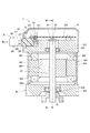
制御ユニット10は、モータ80の軸方向の一方側に一体に構成されている。モータ23および制御ユニット10は、機電一体型式の駆動装置1を構成している。図1に示す形態では、制御ユニット10は、モータ80の出力側とは反対側において、モータ80と同軸に配置されている。なお、他の実施形態では、制御ユニット10は、モータ80の出力側において、モータ80と同軸に配置されてもよい。
The
図2、図3に示すように、モータ80は、三相ブラシレスモータであって、ステータ840、ロータ860、およびそれらを収容するハウジング830を備えている。ステータ840は、ハウジング830に固定されているステータコア845と、ステータコア845に組み付けられている二組の三相巻線組801、802とを有している。第1巻線組801を構成する各相巻線からは、リード線851、853、855が延び出している。第2巻線組802を構成する各相巻線からは、リード線852、854、856が延び出している。
As shown in FIGS. 2 and 3, the
ロータ860は、リア軸受835およびフロント軸受836により支持されているシャフト87と、シャフト87が嵌入されたロータコア865とを有している。ロータ860は、ステータ840の内側に設けられており、ステータ840に対して相対回転可能である。シャフト87の一端には永久磁石88が設けられている。
The
ハウジング830は、筒状のケース834と、ケース834の一端に設けられているリアフレームエンド837と、ケース834の他端に設けられているフロントフレームエンド838とを有している。リアフレームエンド837およびフロントフレームエンド838は、ボルト等により互いに締結されている。各巻線組801、802のリード線851、852等は、リアフレームエンド837のリード線挿通孔839を挿通し、制御ユニット10に接続されている。
The
図4に示すように、巻線組801、802は、電気的特性が同等であり、共通のステータに互いに電気角30[deg]ずらして配置されている。
As shown in FIG. 4, the winding
[第1実施形態]
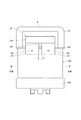
次に、第1実施形態の駆動装置1の構成について、図2〜図13を参照して説明する。図2、図3に示すように、制御ユニット10は、制御部20と、制御部20を覆うカバー21と、制御部20を、外部ケーブル191、192のコネクタである外部コネクタ161、162(図1参照)に接続するためのコネクタ部35等を含む。カバー21は、外部の衝撃から制御部20を保護したり、制御部20内への埃や水等の浸入を防止したりする。
[First Embodiment]
Next, the configuration of the
制御部20は、リアフレームエンド837に固定されている基板230と、基板230に実装されている各種の電子部品とを備えている。図2、図3では電子部品の図示を省略している。電子部品については図5、図6を用いて後述する。基板230は、例えばプリント基板であり、リアフレームエンド837と対向する位置に設けられている。基板230には、二系統分の各電子部品が系統毎に独立して設けられており、完全冗長構成をなしている。第1実施形態では基板230は一枚であるが、他の実施形態では、二枚以上の基板を備えるようにしてもよい。
The
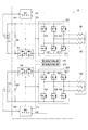
図5に駆動装置1の回路構成を示す。制御部20は、二つの「電力変換器」としてのインバータ601、602、および、二つのマイコン401、402を備える二系統のモータ制御装置であり、二組の巻線組801、802を有するモータ80に電力を供給する。ここで、巻線組、インバータおよびマイコンを含む構成要素の単位を「系統」と定義する。
FIG. 5 shows the circuit configuration of the
明細書中、必要に応じて、第1系統の構成要素又は信号には語頭に「第1」または「第1系統」を付し、第2系統の構成要素又は信号には語頭に「第2」または「第2系統」を付して区別する。各系統に共通の事項については「第1、第2」、「第1系統、第2系統」を付さず、まとめて記載する。また、スイッチング素子を除き、第1系統の構成要素又は信号の符号の末尾に「1」を付し、第2系統の構成要素又は信号の符号の末尾に「2」を付して記す。 In the specification, if necessary, the component or signal of the first system is prefixed with "first" or "first system", and the component or signal of the second system is prefixed with "second". "Or" second system "is added to distinguish. Items common to each system are described together without adding "1st and 2nd" and "1st and 2nd systems". Further, except for the switching element, "1" is added to the end of the code of the component or signal of the first system, and "2" is added to the end of the code of the component or signal of the second system.
制御部20は、インバータ601、602、電源リレー141、142、回転角検出部251、252、および、マイコン401、402等を備えている。第1実施形態では二つの電源111、112から各系統に電力供給される。
The
インバータ601、602は、それぞれ、例えばMOSFET等の6つのスイッチング素子611〜616、621〜626がブリッジ接続されている。第1インバータ601は、第1マイコン401からの駆動信号によりスイッチング動作し、第1電源111の直流電力を変換して、第1巻線組801に供給する。第2インバータ602は、第2マイコン402からの駆動信号によりスイッチング動作し、第2電源112の直流電力を変換して、第2巻線組802に供給する。
In the
電源リレー141、142は、インバータ601、602の各入力部の電源ラインに設けられている。図5に例示する電源リレー141、142は、寄生ダイオードが互いに反対向きの二つのスイッチング素子が直列接続された、電源逆接続時の保護機能を含むものである。ただし、電源リレーは、逆接続防止機能を含まない一つのスイッチング素子や機械式リレーで構成されてもよい。また、インバータ601、602の入力部には、コンデンサ281、282が設けられている。コンデンサ281、282は、電源から入力された電力を平滑化し、また、スイッチング素子のスイッチング動作等に起因するノイズの流出を防止する。また、コンデンサ281、282は、図示しないインダクタと共にフィルタ回路を構成する。
The power relays 141 and 142 are provided in the power supply lines of the input units of the
第1回転角検出部251は、モータ80の電気角θ1を検出し、第1マイコン401に出力する。第2回転角検出部252は、モータ80の電気角θ2を検出し、第2マイコン402に出力する。第1回転角検出部251は、第2回転角検出部252とは独立する電源ラインおよび信号ラインを有する。
The first rotation
第1マイコン401は、操舵トルクtrq1、電流Im1、および、回転角θ1等のフィードバック情報に基づいて、第1インバータ601に指令する駆動信号を演算する。第2マイコン402は、操舵トルクtrq2、電流Im2、および、回転角θ2等のフィードバック情報に基づいて、第2インバータ602に指令する駆動信号を演算する。
The
図6に駆動装置1の制御構成を示す。図6において、第1系統と第2系統は、全て独立した2組の要素群から構成されており、いわゆる「完全二系統」の冗長構成をなしている。制御部20のうち、巻線組801の通電を制御する第1系統の各電子部品は、第1系統制御部201を構成している。また、制御部20のうち、巻線組802の通電を制御する第2系統の各電子部品は、第2系統制御部202を構成している。
FIG. 6 shows the control configuration of the
コネクタ部35は、第1系統制御部201に接続されている第1系統端子群と、それら第1系統端子群を保持する第1系統コネクタ351と、第2系統制御部202に接続されている第2系統端子群と、それら第2系統端子群を保持する第2系統コネクタ352とを有する。
The
第1系統端子には、第1系統制御部201に電源を供給するための第1電源端子131と、第1系統制御部201に信号を入力するための第1車両通信端子321および第1トルク信号端子331とが含まれる。第2系統端子には、第2系統制御部202に電源を供給するための第2電源端子132と、第2系統制御部202に信号を入力するための第2車両通信端子322および第2トルク信号端子332とが含まれる。
The first system terminals include a first
第1電源端子131は、第1電源111に接続される。第1電源111の電力は、第1電源端子131、第1電源リレー141および第1インバータ601を経由して、第1巻線組801に供給される。また、第1電源111の電力は、第1マイコン401および第1系統のセンサ類にも供給される。
The first
第2電源端子132は、第2電源112に接続される。第2電源112の電力は、第2電源端子132、第2電源リレー142および第2インバータ602を経由して、第2巻線組802に供給される。また、第2電源112の電力は、第2マイコン402および第2系統のセンサ類にも供給される。
The second
車両通信ネットワークとしてCANが冗長的に設けられる場合、第1車両通信端子311は、第1CAN301と第1車両通信回路321との間に接続される。第2車両通信端子312は、第2CAN302と第2車両通信回路322との間に接続される。CANが冗長的に設けられない場合、二系統の車両通信端子311、312は、共通のCANに接続されてもよい。また、CAN以外の車両通信ネットワークとして、CAN−FD(CAN with Flexible Data rate)やFlexRay等、どのような規格のネットワークが用いられてもよい。
When CAN is redundantly provided as a vehicle communication network, the first
第1トルク信号端子331は、第1トルクセンサ931と第1トルクセンサ入力回路341との間に接続される。第1トルクセンサ入力回路341は、第1トルク信号端子331が検出した操舵トルクtrq1を第1マイコン401に通知する。第2トルク信号端子332は、第2トルクセンサ932と第2トルクセンサ入力回路342との間に接続される。第2トルクセンサ入力回路342は、第2トルク信号端子332が検出した操舵トルクtrq2を第2マイコン402に通知する。
The first
マイコン401、402は、マイコン間通信により相互に情報を送受信可能である。制御部20は、一方の系統に異常が発生している場合、正常な他方の系統でモータ制御を継続する。
The
図2、図7、図8、図9にコネクタ部35の構成を示す。以下、モータ80の軸心Axに直交する方向を「径方向」と記載する。コネクタ部35は、ベース部350と、コネクタ351、352と、電源端子131、132と、「第1信号端子」としての第1車両通信端子321および第1トルク信号端子331と、「第2信号端子」としての第2車両通信端子322および第2トルク信号端子332とを有する。ベース部350は、スクリュー15により基板230に固定されている。ベース部350の一部は、カバー21の開口部211を通じてカバー21外に出ている。コネクタ351、352は、ベース部350から径方向に突き出している。
2, FIG. 7, FIG. 8 and FIG. 9 show the configuration of the
第1系統コネクタ351は、第1電源端子131、第1車両通信端子311および第1トルク信号端子331を保持している。第2系統コネクタ352は、第2電源端子132、第2車両通信端子312および第2トルク信号端子332を保持している。第1系統コネクタ351の挿抜方向は、第2系統コネクタ352の挿抜方向と同じであって、径方向である。挿抜方向とは、外部コネクタをコネクタ351、352に挿抜するときの方向であって、コネクタ351、352の間口の向きと一致する。間口は、コネクタ351、352の先端の開口部のことである。
The
図7に示すように、第1系統コネクタ351と第2系統コネクタ352は、それらコネクタの間隔Gが両方のコネクタの短手方向幅Wよりも小さくなるように、互いに近接して配置されている。第1実施形態では、第1系統コネクタ351と第2系統コネクタ352は、それらコネクタの間口の長手方向が一直線上に並ぶように配置されている。第1系統コネクタ351と第2系統コネクタ352との間に、それらコネクタを接続するリブ390が形成されている。
As shown in FIG. 7, the
第1電源端子131は、第1信号端子と比べて、第1系統コネクタ351の間口のうち第2系統コネクタ352に近い方に配置されている。第1実施形態では、第1電源端子131は、第1系統コネクタ351の間口のうち、間口の長手方向の第2系統コネクタ352側に配置されている。そして、第1信号端子は、第1系統コネクタ351の間口のうち、間口の長手方向の第2系統コネクタ352とは反対側に配置されている。
The first
第2電源端子132は、第2信号端子と比べて、第2系統コネクタ352の間口のうち第1系統コネクタ351に近い方に配置されている。第1実施形態では、第2電源端子132は、第2系統コネクタ352の間口のうち、間口の長手方向の第1系統コネクタ351側に配置されている。そして、第2信号端子は、第2系統コネクタ352の間口のうち、間口の長手方向の第1系統コネクタ351とは反対側に配置されている。
The second
第1実施形態では、コネクタ351、352間に位置する境界面Bを境に、第1系統端子(第1電源端子131、第1車両通信端子321および第1トルク信号端子331)と第2系統端子(第2電源端子132、第2車両通信端子322および第2トルク信号端子332)とが、電源端子131、132が中央に位置するようにしてミラー配置されている。第1電源端子131と第2電源端子132がコネクタ配置スペースの中央部に寄せて配置され、信号端子がコネクタ配置スペースの両端部に配置されている。
In the first embodiment, the first system terminal (first
図6に示す第1回転角検出部251と第2回転角検出部252は、共にパッケージ化されて図9に示す回転角センサ25を構成している。第1系統制御部201と第2系統制御部202は、1つの基板230に実装されている。図9に示すように、第1系統制御部201の実装領域A1は、基板230のうち、回転角センサ25を通り且つ軸心Axと平行な境界面Bに対して一方に配置されている。第2系統制御部202の実装領域A2は、基板230のうち、境界面Bに対して他方に配置されている。つまり、境界面Bで第1系統制御部201と第2系統制御部202が分かれている。
The first rotation
第1電源リレー141、第1コンデンサ281および第1インバータ601は、第1系統制御部201の第1パワー系部品である。第2電源リレー142、第2コンデンサ282および第2インバータ602は、第2系統制御部202の第2パワー系部品である。一方、第1車両通信回路321、第1トルクセンサ入力回路341、第1マイコン401および第1回転角検出部251は、第1系統制御部201の第1制御系部品である。第2車両通信回路322、第2トルクセンサ入力回路342、第2マイコン402および第2回転角検出部252は、第2系統制御部202の第2制御系部品である。図9に示すように、パワー系部品の実装エリアApは、制御系部品の実装エリアAcよりもコネクタ351、352寄りに位置する。つまり、パワー系部品は、制御系部品と比べて、基板230のうちコネクタ351、352に近い方に配置されている。
The first
図7に示すように、第1系統コネクタ351は境界面Bに対して一方に配置されており、第2系統コネクタ352は境界面Bに対して他方に配置されている。そして、境界面Bに対して一方側には、境界面Bから順に第1電源端子131および第1信号端子が配置されている。また、境界面Bに対して他方側には、境界面Bから順に第2電源端子132および第2信号端子が配置されている。
As shown in FIG. 7, the
図2、図7、図8に示すように、コネクタ351、352は、それらコネクタ351、352の並び方向に対して直交する方向に突き出す突起391、392を有する。つまり、突起391、392は、コネクタ351、352の並び方向に突き出しておらず、コネクタ間の隙間には形成されていない。第1実施形態では、コネクタ351、352の間口形状は矩形状である。コネクタ351、352は、一対の長辺部と、一対の短辺部とから構成されている。突起391、392は、長辺部に形成されており、短辺部には形成されていない。間隔Gは、突起391、392の高さの4倍以下に設定される。
As shown in FIGS. 2, 7, and 8, the
図10〜図13に示すように、外部コネクタ161、162は、コネクタ351、352の間口に嵌合する。外部コネクタ161、162には、突起391、392に対応する位置を中心として回動するレバー181、182が設けられている。外部コネクタ161、162は、コネクタ351、352への挿入時に突起391、392との干渉を避けるための切欠き溝175、176を有する。レバー181、182にも、コネクタ351、352への挿入時の干渉を避けるための係合溝185、186が設けられている。車両に搭載する際、作業者がレバー181、182を押し、外部コネクタ161、162がコネクタ351、352へ挿入され、間口に嵌合される。すなわち、レバー181、182が図10の状態から図12の状態に回動するにつれて、外部コネクタ161、162は挿入方向に移動する。そして、レバー181、182が図12の状態まで回動したとき、係合溝185、186は挿抜方向と直交する方向に位置し、外部コネクタ161、162が抜け落ちることを防止する。ここで、レバー181、182を図12の状態で固定するため、外部コネクタ161、162に爪部を、レバー181、182に孔部を設け、両者を嵌合するよう構成してもよい。また、係合溝185、186は、レバー181、182が図10の状態から図12の状態まで回動すると、挿抜方向において突起391、392と係合するようにしてもよい。突起391、392は、外部コネクタ161、162のレバー181、182を係止させるものであり、レバー181、182をロックするためのものであってもよい。
As shown in FIGS. 10 to 13, the
図11、図13に示すように、第1系統コネクタ351に対して第2系統コネクタ352とは反対側には、第1系統コネクタ351の突起391に係止させる第1レバー181を、係止状態(図13参照)と非係止状態(図11参照)の間で切り替え操作するためのスペースS1が設けられる。第2系統コネクタ352に対して第1系統コネクタ351とは反対側には、第2系統コネクタ352の突起392に係止させる第2レバー182を、係止状態と非係止状態の間で切り替え操作するためのスペースS2が設けられる。
As shown in FIGS. 11 and 13, a
(効果)
以上説明したように、第1実施形態では、第1系統コネクタ351の挿抜方向は、第2系統コネクタ352の挿抜方向と同じである。第1系統コネクタ351と第2系統コネクタ352は、それらコネクタの間隔Gが両方のコネクタの短手方向幅Wよりも小さくなるように、互いに近接して配置されている。第1電源端子131は、第1信号端子と比べて、第1系統コネクタ351の間口のうち第2系統コネクタ352に近い方に配置されている。第2電源端子132は、第2信号端子と比べて、第2系統コネクタ352の間口のうち第1系統コネクタ351に近い方に配置されている。
(effect)
As described above, in the first embodiment, the insertion / removal direction of the
このように第1電源端子131と第2電源端子132がコネクタ配置スペースの中央に寄せて配置されることで、電源ラインと信号ラインの交差を回避し易くなる。また、電源ラインのループ面積の増加が抑えられる。したがって、信号ラインへのノイズ影響を低減することができる。一方の系統に異常が発生し、正常な他方の系統のみでモータ制御を継続している場合にもノイズ影響が生じる懸念があるが、このような場合であっても電源端子がコネクタ配置スペースの中央に寄せて配置されることで、ノイズ影響を低減することができる。
By arranging the first
また、第1実施形態では、コネクタ351、352間に位置する境界面Bを境に、第1系統端子(第1電源端子131、第1車両通信端子321および第1トルク信号端子331)と第2系統端子(第2電源端子132、第2車両通信端子322および第2トルク信号端子332)とが、電源端子131、132が中央に位置するようにしてミラー配置されている。これにより、第1電源端子131と第2電源端子132をコネクタ配置スペースの中央に寄せて配置することができる。
Further, in the first embodiment, the first system terminal (first
また、第1実施形態では、第1系統コネクタ351と第2系統コネクタ352は、それらコネクタの間口の長手方向が一直線上に並ぶように配置されている。これにより、第1電源端子131と第2電源端子132をコネクタ配置スペースの中央に寄せて配置し易くなる。
Further, in the first embodiment, the
また、第1実施形態では、第1系統制御部201と第2系統制御部202は、1つの基板230に実装されている。そして、境界面Bで第1系統制御部201と第2系統制御部202が分かれている。これにより、電源ラインと信号ラインが交差しないように、第1系統端子と基板230上の第1系統制御部201とを接続し、また、第2系統端子と基板230上の第2系統制御部202とを接続することができる。
Further, in the first embodiment, the first
また、第1実施形態では、制御部201、202のパワー系部品は、制御部201、202の制御系部品と比べて、基板230のうちコネクタ351、352に近い方に配置されている。これにより、比較的大きな電流が流れる電源ラインの基板配線経路が短くなるので、電源ラインのループ面積が小さくなり、信号ラインへのノイズ影響を低減することができるとともに、発熱(すなわち電流ロス)を低減することができる。
Further, in the first embodiment, the power system components of the
また、第1実施形態では、境界面Bに対して一方側には、境界面Bから順に第1電源端子131および第1信号端子が配置されている。また、境界面Bに対して他方側には、境界面Bから順に第2電源端子132および第2信号端子が配置されている。これにより、電源ラインと信号ラインが交差しないように、第1系統端子と基板230上の第1系統制御部201とを接続し、また、第2系統端子と基板230上の第2系統制御部202とを接続することができる。
Further, in the first embodiment, the first
また、第1実施形態では、コネクタ351、352は、それらコネクタ351、352の並び方向に対して直交する方向に突き出す突起391、392を有する。つまり、突起391、392は、コネクタ351、352の並び方向に突き出しておらず、コネクタ間の隙間には形成されていない。これにより、突起391、392同士が離間するので、コネクタ351、352同士を近づけることができる。そのため、コネクタ設置スペースが小さくなり、駆動装置1の体格を小型化することができる。また、突起391、392同士が離間するので、コネクタ351、352にそれぞれ外部コネクタ161、162を接続するときの作業スペース、すなわち外部コネクタ161、162のレバー181、182を操作するためのスペースに余裕が生まれ、組み付け性が向上する。
Further, in the first embodiment, the
また、第1実施形態では、第1系統コネクタ351に対して第2系統コネクタ352とは反対側には、第1レバー181を係止状態と非係止状態の間で切り替え操作するためのスペースS1が設けられる。第2系統コネクタ352に対して第1系統コネクタ351とは反対側には、レバー182を係止状態と非係止状態の間で切り替え操作するためのスペースS2が設けられる。そのため、外部コネクタ161、162の着脱時の作業エリアが確保され、作業性が向上する。また、外部コネクタ161、162の装着状態での全体の小型化が実現できる。
Further, in the first embodiment, on the side opposite to the
また、第1実施形態では、第1系統コネクタ351と第2系統コネクタ352との間に、それらコネクタ351、352を接続するリブ390が形成されている。これにより、コネクタ部35の強度向上および変形抑制が得られ、また、背面リブが不要になり、小型化することができる。
Further, in the first embodiment,
[第2実施形態]
第2実施形態では、図14、図15に示すように、コネクタ部36の第1系統コネクタ361と第2系統コネクタ362は一体に形成されている。上記以外は、第2実施形態は、第1実施形態と同様の構成であり、第1実施形態と同様の効果を奏する。
[Second Embodiment]
In the second embodiment, as shown in FIGS. 14 and 15, the
[第3実施形態]
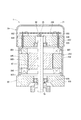
第3実施形態では、図16〜図20に示すように、コネクタ部37のコネクタ371、372は、ベース部370から軸方向へ突き出している。コネクタ371、372の挿抜方向および間口の向きは軸方向である。上記以外は、第3実施形態は、第1実施形態と同様の構成であり、第1実施形態と同様の効果を奏する。なお、図18ではモータ80の構成部材の図示を省略している。
[Third Embodiment]
In the third embodiment, as shown in FIGS. 16 to 20, the
[第4実施形態]
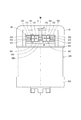
第4実施形態では、図21〜図23に示すように、コネクタ部38のコネクタ381、382は、ベース部380からカバー22の底部220の開口部221を通じて軸方向へ突き出している。コネクタ381、382の挿抜方向および間口の向きは軸方向である。コネクタ381、382は、それらコネクタの間口の長手方向がなす角度が90以上となるように配置されている。上記以外は、第4実施形態は、第1実施形態と同様の構成であり、第1実施形態と同様の効果を奏する。
[Fourth Embodiment]
In the fourth embodiment, as shown in FIGS. 21 to 23, the
[他の実施形態]
他の実施形態では、共通の一つの電源から分岐して各系統に電力供給されるようにしてもよい。それでも、系統毎に電源端子が設けられ、それら電源端子が各系統コネクタに分けて配置されていればよい。電源が共通のものである場合、系統毎に電源に設けられる場合と比べるとノイズ影響が出やすいが、第1実施形態と同様に電源端子がコネクタ配置スペースの中央に寄せて配置されることで、ノイズ影響を低減することができる。
[Other Embodiments]
In another embodiment, power may be supplied to each system by branching from one common power source. Nevertheless, it is sufficient that power supply terminals are provided for each system and those power supply terminals are separately arranged for each system connector. When the power supply is common, noise is more likely to occur compared to the case where the power supply is provided for each system, but as in the first embodiment, the power supply terminals are arranged closer to the center of the connector arrangement space. , The influence of noise can be reduced.
他の実施形態では、第1系統コネクタと第2系統コネクタとの間の位置が、第1系統制御部と第2系統制御部との境界位置から外れていてもよい。 In another embodiment, the position between the first system connector and the second system connector may deviate from the boundary position between the first system control unit and the second system control unit.
第1〜第4実施形態では、コネクタ部のベース部およびコネクタがカバーとは別部材から構成されていた。これに対して、他の実施形態では、ベース部、コネクタ、およびカバーが同一部材から構成されてもよい。このような形態では、コネクタ部の端子が制御部の基板に例えばプレスフィット等で接続されるか、または、制御部の基板がコネクタ部に固定されると共に、巻線組のリード線が制御部の基板に例えばプレスフィット等で接続される。 In the first to fourth embodiments, the base portion of the connector portion and the connector are made of a member separate from the cover. On the other hand, in other embodiments, the base portion, the connector, and the cover may be composed of the same member. In such a form, the terminal of the connector part is connected to the board of the control part by, for example, press-fitting, or the board of the control part is fixed to the connector part, and the lead wire of the winding set is connected to the control part. It is connected to the substrate of the above by, for example, press fit.
他の実施形態では、モータは、二組の巻線組が同位相で配置されるものでもよい。また、また、モータの相の数は、三相に限らず四相以上でもよい。さらに駆動対象のモータは、交流ブラシレスモータに限らず、ブラシ付き直流モータとしてもよい。その場合、「電力変換器」としてHブリッジ回路を用いてもよい。また、他の実施形態では、駆動装置は、電動パワーステアリング装置に限らず、他のいかなる用途に適用されてもよい。 In other embodiments, the motor may have two sets of windings arranged in phase. Further, the number of phases of the motor is not limited to three, and may be four or more. Further, the motor to be driven is not limited to the AC brushless motor, and may be a DC motor with a brush. In that case, an H-bridge circuit may be used as the "power converter". Further, in other embodiments, the drive device is not limited to the electric power steering device, and may be applied to any other application.
本発明は、上述した実施形態に限定されるものではなく、発明の趣旨を逸脱しない範囲で種々の形態で実施可能である。 The present invention is not limited to the above-described embodiment, and can be implemented in various forms without departing from the spirit of the invention.
131・・・第1電源端子、 132・・・第2電源端子、 161、162・・・外部コネクタ、 20・・・制御部、 201・・・第1系統制御部、 202・・・第2系統制御部、 311・・・第1車両通信端子(第1信号端子)、 312・・・第2車両通信端子(第2信号端子)、 321・・・第1トルク信号端子(第1信号端子)、 322・・・第2トルク信号端子(第2信号端子)、 35、36、37、38・・・コネクタ部、 351、361、371、381・・・第1系統コネクタ、 352、362、372、382・・・第2系統コネクタ、 80・・・モータ、 801、802・・・巻線組、 G・・・間隔、 W・・・短手方向幅 131 ... 1st power supply terminal, 132 ... 2nd power supply terminal, 161, 162 ... External connector, 20 ... Control unit, 201 ... 1st system control unit, 202 ... 2nd System control unit, 311 ... 1st vehicle communication terminal (1st signal terminal), 312 ... 2nd vehicle communication terminal (2nd signal terminal), 321 ... 1st torque signal terminal (1st signal terminal) ), 322 ... 2nd torque signal terminal (2nd signal terminal), 35, 36, 37, 38 ... Connector part, 351, 361, 371, 381 ... 1st system connector, 352, 362, 372, 382 ... 2nd system connector, 80 ... motor, 801, 802 ... winding set, G ... spacing, W ... short direction width
Claims (6)
前記モータと同軸に配置され、前記モータの駆動を制御する制御部(20)と、
外部ケーブルのコネクタである外部コネクタ(161、162)と接続するためのコネクタ部(35、36、37、38)と、を備え、
前記制御部は、一方の前記巻線組の通電を制御する第1系統制御部(201)と、他方の前記巻線組の通電を制御する第2系統制御部(202)とを有し、
前記第1系統制御部と前記第2系統制御部は、1つの基板(230)に実装されており、
前記コネクタ部は、前記第1系統制御部に電源を供給するための第1電源端子(131)と、前記第1系統制御部に信号を入力するための第1信号端子(311、321)と、前記第1電源端子および前記第1信号端子を保持する第1系統コネクタ(351、361、371、381)と、前記第2系統制御部に電源を供給するための第2電源端子(132)と、前記第2系統制御部に信号を入力するための第2信号端子(312、322)と、前記第2電源端子および前記第2信号端子を保持する第2系統コネクタ(352、362、372、382)と、を有し、
前記第1系統コネクタの挿抜方向が前記第2系統コネクタの挿抜方向と同じであり、
前記第1系統コネクタと前記第2系統コネクタは、それらコネクタの間隔(G)が両方のコネクタの短手方向幅(W)よりも小さくなるように、互いに近接して配置されており、
前記第1電源端子は、前記第1信号端子と比べて、前記第1系統コネクタの間口のうち前記第2系統コネクタに近い方に配置されており、
前記第2電源端子は、前記第2信号端子と比べて、前記第2系統コネクタの間口のうち前記第1系統コネクタに近い方に配置されている駆動装置。 A motor (80) having two winding sets (801, 802) and
A control unit (20) arranged coaxially with the motor and controlling the drive of the motor,
A connector portion (35, 36, 37, 38) for connecting to an external connector (161, 162), which is a connector for an external cable, is provided.
The control unit includes a first system control unit (201) that controls energization of one of the winding sets and a second system control unit (202) that controls energization of the other winding set.
The first system control unit and the second system control unit are mounted on one substrate (230).
The connector unit includes a first power supply terminal (131) for supplying power to the first system control unit and a first signal terminal (311 and 321) for inputting a signal to the first system control unit. , The first system connector (351, 361, 371, 381) holding the first power supply terminal and the first signal terminal, and the second power supply terminal (132) for supplying power to the second system control unit. A second signal terminal (312, 322) for inputting a signal to the second system control unit, and a second system connector (352, 362, 372) holding the second power supply terminal and the second signal terminal. , 382), and
The insertion / removal direction of the first system connector is the same as the insertion / removal direction of the second system connector.
The first system connector and the second system connector are arranged close to each other so that the distance (G) between the connectors is smaller than the lateral width (W) of both connectors.
The first power supply terminal is arranged closer to the second system connector in the frontage of the first system connector than the first signal terminal.
The second power supply terminal is a drive device arranged closer to the first system connector in the frontage of the second system connector as compared with the second signal terminal.
前記第2系統制御部は、前記モータの回転角度を検出する第2回転角検出部(252)を含み、
前記第1回転角検出部は、前記第2回転角検出部とは独立する電源ラインおよび信号ラインを有し、前記第2回転角検出部と共にパッケージ化されて回転角度センサ(25)を構成しており、
前記回転角センサを通り且つ前記モータの軸心と平行な境界面(S)で前記第1系統制御部と前記第2系統制御部とが分かれている請求項1〜3のいずれか一項に記載の駆動装置。 The first system control unit includes a first rotation angle detection unit (251) that detects the rotation angle of the motor.
The second system control unit includes a second rotation angle detection unit (252) that detects the rotation angle of the motor.
The first rotation angle detection unit has a power supply line and a signal line independent of the second rotation angle detection unit, and is packaged together with the second rotation angle detection unit to form a rotation angle sensor (25). and,
The item according to any one of claims 1 to 3, wherein the first system control unit and the second system control unit are separated at a boundary surface (S) that passes through the rotation angle sensor and is parallel to the axis of the motor. The drive device described.
前記第2系統制御部は、前記第2電源端子に接続されている第2パワー系部品(142、282、602)、および、前記第2信号端子に接続されている第2制御系部品(252、322、342、402)を有し、
前記第1パワー系部品および前記第2パワー系部品は、前記第1制御系部品および前記第2制御系部品と比べて、前記基板のうち前記第1系統コネクタおよび前記第2系統コネクタに近い方に配置されている請求項4に記載の駆動装置。 The first system control unit includes a first power system component (141, 281, 601) connected to the first power supply terminal, and a first control system component (251) connected to the first signal terminal. , 321, 341, 401)
The second system control unit includes a second power system component (142, 282, 602) connected to the second power supply terminal, and a second control system component (252) connected to the second signal terminal. , 322, 342, 402)
The first power system component and the second power system component are closer to the first system connector and the second system connector of the board than the first control system component and the second control system component. The drive device according to claim 4, which is arranged in.
前記境界面に対して他方側には、前記境界面から順に前記第2電源端子および前記第2信号端子が配置されている請求項4または5に記載の駆動装置。 On one side of the boundary surface, the first power supply terminal and the first signal terminal are arranged in order from the boundary surface.
The driving device according to claim 4 or 5, wherein the second power supply terminal and the second signal terminal are arranged in order from the boundary surface on the other side with respect to the boundary surface.
Priority Applications (4)
| Application Number | Priority Date | Filing Date | Title |
|---|---|---|---|
| JP2018075412A JP6907991B2 (en) | 2018-04-10 | 2018-04-10 | Drive device |
| PCT/JP2019/015271 WO2019198655A1 (en) | 2018-04-10 | 2019-04-08 | Drive device |
| CN201980024349.XA CN111937280B (en) | 2018-04-10 | 2019-04-08 | Drive device |
| US17/034,336 US11801887B2 (en) | 2018-04-10 | 2020-09-28 | Drive device |
Applications Claiming Priority (1)
| Application Number | Priority Date | Filing Date | Title |
|---|---|---|---|
| JP2018075412A JP6907991B2 (en) | 2018-04-10 | 2018-04-10 | Drive device |
Publications (3)
| Publication Number | Publication Date |
|---|---|
| JP2019187078A JP2019187078A (en) | 2019-10-24 |
| JP2019187078A5 JP2019187078A5 (en) | 2020-05-07 |
| JP6907991B2 true JP6907991B2 (en) | 2021-07-21 |
Family
ID=68164108
Family Applications (1)
| Application Number | Title | Priority Date | Filing Date |
|---|---|---|---|
| JP2018075412A Active JP6907991B2 (en) | 2018-04-10 | 2018-04-10 | Drive device |
Country Status (4)
| Country | Link |
|---|---|
| US (1) | US11801887B2 (en) |
| JP (1) | JP6907991B2 (en) |
| CN (1) | CN111937280B (en) |
| WO (1) | WO2019198655A1 (en) |
Families Citing this family (2)
| Publication number | Priority date | Publication date | Assignee | Title |
|---|---|---|---|---|
| US20240072617A1 (en) * | 2021-02-19 | 2024-02-29 | Jtekt Corporation | Motor control device |
| JP2022178464A (en) * | 2021-05-20 | 2022-12-02 | 株式会社デンソー | Driving device |
Family Cites Families (17)
| Publication number | Priority date | Publication date | Assignee | Title |
|---|---|---|---|---|
| JP3774624B2 (en) * | 2000-10-18 | 2006-05-17 | 三菱電機株式会社 | Electric power steering device |
| JP2011129350A (en) * | 2009-12-17 | 2011-06-30 | Tyco Electronics Japan Kk | Connector mounting substrate and manufacturing method of connector mounting substrate |
| JP5012953B2 (en) * | 2010-05-21 | 2012-08-29 | 株式会社デンソー | Drive device |
| JP6179476B2 (en) * | 2014-07-31 | 2017-08-16 | 株式会社デンソー | DRIVE DEVICE AND ELECTRIC POWER STEERING DEVICE USING THE SAME |
| US10167012B2 (en) | 2014-10-22 | 2019-01-01 | Mitsubishi Electric Corporation | Electric power steering device |
| WO2016075789A1 (en) * | 2014-11-13 | 2016-05-19 | 三菱電機株式会社 | Control unit and electric power steering device using same |
| WO2016075821A1 (en) * | 2014-11-14 | 2016-05-19 | 三菱電機株式会社 | Control unit and electric power steering device using same |
| JP6439572B2 (en) * | 2015-04-28 | 2018-12-19 | 株式会社デンソー | Electronic control device and driving device |
| JP6610225B2 (en) | 2015-12-08 | 2019-11-27 | 株式会社デンソー | Drive device |
| CN109070933B (en) | 2016-04-06 | 2021-03-19 | 三菱电机株式会社 | Electric power steering apparatus |
| JP6680054B2 (en) | 2016-04-06 | 2020-04-15 | 株式会社デンソー | Drive device and electric power steering device using the same |
| JP6289530B2 (en) * | 2016-04-14 | 2018-03-07 | 三菱電機株式会社 | DRIVE DEVICE INTEGRATED ROTARY ELECTRIC AND ELECTRIC POWER STEERING DEVICE |
| JP6721267B2 (en) * | 2017-06-05 | 2020-07-08 | 三菱電機株式会社 | Driving device integrated rotating electric machine and electric power steering device using the same |
| JP7124401B2 (en) * | 2018-04-10 | 2022-08-24 | 株式会社デンソー | drive |
| JP7124400B2 (en) * | 2018-04-10 | 2022-08-24 | 株式会社デンソー | drive |
| US20210075301A1 (en) * | 2018-08-24 | 2021-03-11 | Mitsubishi Electric Corporation | Electric power steering apparatus |
| JP7167635B2 (en) * | 2018-11-02 | 2022-11-09 | 株式会社デンソー | Driving device and electric power steering device using the same |
-
2018
- 2018-04-10 JP JP2018075412A patent/JP6907991B2/en active Active
-
2019
- 2019-04-08 WO PCT/JP2019/015271 patent/WO2019198655A1/en active Application Filing
- 2019-04-08 CN CN201980024349.XA patent/CN111937280B/en active Active
-
2020
- 2020-09-28 US US17/034,336 patent/US11801887B2/en active Active
Also Published As
| Publication number | Publication date |
|---|---|
| US11801887B2 (en) | 2023-10-31 |
| US20210009192A1 (en) | 2021-01-14 |
| WO2019198655A1 (en) | 2019-10-17 |
| JP2019187078A (en) | 2019-10-24 |
| CN111937280A (en) | 2020-11-13 |
| CN111937280B (en) | 2023-03-28 |
Similar Documents
| Publication | Publication Date | Title |
|---|---|---|
| JP7124401B2 (en) | drive | |
| JP6907992B2 (en) | Drive unit and drive unit | |
| JP7124400B2 (en) | drive | |
| JP7167635B2 (en) | Driving device and electric power steering device using the same | |
| JP2017189033A (en) | Drive device, and electric power steering apparatus using the same | |
| CN111183570B (en) | Electric power steering apparatus | |
| JP7244216B2 (en) | Rotating electric machine controller | |
| US11081995B2 (en) | Motor control device | |
| US11801887B2 (en) | Drive device | |
| US20210339794A1 (en) | Drive device | |
| JP7211288B2 (en) | drive | |
| JP2022056881A (en) | Motor drive system | |
| JP2009071953A (en) | Driving device | |
| WO2022196458A1 (en) | Drive device | |
| JP2023116049A (en) | Driving device | |
| CN111404396A (en) | Power conversion device, drive device, and power steering device | |
| JP2023116027A (en) | Driving device | |
| JP2022028472A (en) | Multiple motor drive system | |
| WO2019077647A1 (en) | Electric power steering apparatus |
Legal Events
| Date | Code | Title | Description |
|---|---|---|---|
| A521 | Request for written amendment filed |
Free format text: JAPANESE INTERMEDIATE CODE: A523 Effective date: 20200326 |
|
| A621 | Written request for application examination |
Free format text: JAPANESE INTERMEDIATE CODE: A621 Effective date: 20200326 |
|
| TRDD | Decision of grant or rejection written | ||
| A01 | Written decision to grant a patent or to grant a registration (utility model) |
Free format text: JAPANESE INTERMEDIATE CODE: A01 Effective date: 20210601 |
|
| A61 | First payment of annual fees (during grant procedure) |
Free format text: JAPANESE INTERMEDIATE CODE: A61 Effective date: 20210614 |
|
| R151 | Written notification of patent or utility model registration |
Ref document number: 6907991 Country of ref document: JP Free format text: JAPANESE INTERMEDIATE CODE: R151 |