WO2016047505A1 - 基地局及びユーザ装置 - Google Patents
基地局及びユーザ装置 Download PDFInfo
- Publication number
- WO2016047505A1 WO2016047505A1 PCT/JP2015/076172 JP2015076172W WO2016047505A1 WO 2016047505 A1 WO2016047505 A1 WO 2016047505A1 JP 2015076172 W JP2015076172 W JP 2015076172W WO 2016047505 A1 WO2016047505 A1 WO 2016047505A1
- Authority
- WO
- WIPO (PCT)
- Prior art keywords
- antenna
- channel state
- base station
- state information
- reference signal
- Prior art date
Links
Images


Classifications
-
- H—ELECTRICITY
- H04—ELECTRIC COMMUNICATION TECHNIQUE
- H04B—TRANSMISSION
- H04B7/00—Radio transmission systems, i.e. using radiation field
- H04B7/02—Diversity systems; Multi-antenna system, i.e. transmission or reception using multiple antennas
- H04B7/04—Diversity systems; Multi-antenna system, i.e. transmission or reception using multiple antennas using two or more spaced independent antennas
- H04B7/06—Diversity systems; Multi-antenna system, i.e. transmission or reception using multiple antennas using two or more spaced independent antennas at the transmitting station
- H04B7/0613—Diversity systems; Multi-antenna system, i.e. transmission or reception using multiple antennas using two or more spaced independent antennas at the transmitting station using simultaneous transmission
- H04B7/0615—Diversity systems; Multi-antenna system, i.e. transmission or reception using multiple antennas using two or more spaced independent antennas at the transmitting station using simultaneous transmission of weighted versions of same signal
- H04B7/0619—Diversity systems; Multi-antenna system, i.e. transmission or reception using multiple antennas using two or more spaced independent antennas at the transmitting station using simultaneous transmission of weighted versions of same signal using feedback from receiving side
- H04B7/0621—Feedback content
- H04B7/0626—Channel coefficients, e.g. channel state information [CSI]
-
- H—ELECTRICITY
- H04—ELECTRIC COMMUNICATION TECHNIQUE
- H04B—TRANSMISSION
- H04B7/00—Radio transmission systems, i.e. using radiation field
- H04B7/02—Diversity systems; Multi-antenna system, i.e. transmission or reception using multiple antennas
- H04B7/04—Diversity systems; Multi-antenna system, i.e. transmission or reception using multiple antennas using two or more spaced independent antennas
- H04B7/0413—MIMO systems
- H04B7/0456—Selection of precoding matrices or codebooks, e.g. using matrices antenna weighting
- H04B7/0478—Special codebook structures directed to feedback optimisation
-
- H—ELECTRICITY
- H04—ELECTRIC COMMUNICATION TECHNIQUE
- H04B—TRANSMISSION
- H04B7/00—Radio transmission systems, i.e. using radiation field
- H04B7/02—Diversity systems; Multi-antenna system, i.e. transmission or reception using multiple antennas
- H04B7/04—Diversity systems; Multi-antenna system, i.e. transmission or reception using multiple antennas using two or more spaced independent antennas
- H04B7/0413—MIMO systems
- H04B7/0456—Selection of precoding matrices or codebooks, e.g. using matrices antenna weighting
- H04B7/0478—Special codebook structures directed to feedback optimisation
- H04B7/0479—Special codebook structures directed to feedback optimisation for multi-dimensional arrays, e.g. horizontal or vertical pre-distortion matrix index [PMI]
-
- H—ELECTRICITY
- H04—ELECTRIC COMMUNICATION TECHNIQUE
- H04B—TRANSMISSION
- H04B7/00—Radio transmission systems, i.e. using radiation field
- H04B7/02—Diversity systems; Multi-antenna system, i.e. transmission or reception using multiple antennas
- H04B7/04—Diversity systems; Multi-antenna system, i.e. transmission or reception using multiple antennas using two or more spaced independent antennas
- H04B7/06—Diversity systems; Multi-antenna system, i.e. transmission or reception using multiple antennas using two or more spaced independent antennas at the transmitting station
- H04B7/0613—Diversity systems; Multi-antenna system, i.e. transmission or reception using multiple antennas using two or more spaced independent antennas at the transmitting station using simultaneous transmission
- H04B7/0615—Diversity systems; Multi-antenna system, i.e. transmission or reception using multiple antennas using two or more spaced independent antennas at the transmitting station using simultaneous transmission of weighted versions of same signal
- H04B7/0617—Diversity systems; Multi-antenna system, i.e. transmission or reception using multiple antennas using two or more spaced independent antennas at the transmitting station using simultaneous transmission of weighted versions of same signal for beam forming
-
- H—ELECTRICITY
- H04—ELECTRIC COMMUNICATION TECHNIQUE
- H04B—TRANSMISSION
- H04B7/00—Radio transmission systems, i.e. using radiation field
- H04B7/02—Diversity systems; Multi-antenna system, i.e. transmission or reception using multiple antennas
- H04B7/04—Diversity systems; Multi-antenna system, i.e. transmission or reception using multiple antennas using two or more spaced independent antennas
- H04B7/06—Diversity systems; Multi-antenna system, i.e. transmission or reception using multiple antennas using two or more spaced independent antennas at the transmitting station
- H04B7/0613—Diversity systems; Multi-antenna system, i.e. transmission or reception using multiple antennas using two or more spaced independent antennas at the transmitting station using simultaneous transmission
- H04B7/0615—Diversity systems; Multi-antenna system, i.e. transmission or reception using multiple antennas using two or more spaced independent antennas at the transmitting station using simultaneous transmission of weighted versions of same signal
- H04B7/0619—Diversity systems; Multi-antenna system, i.e. transmission or reception using multiple antennas using two or more spaced independent antennas at the transmitting station using simultaneous transmission of weighted versions of same signal using feedback from receiving side
-
- H—ELECTRICITY
- H04—ELECTRIC COMMUNICATION TECHNIQUE
- H04B—TRANSMISSION
- H04B7/00—Radio transmission systems, i.e. using radiation field
- H04B7/02—Diversity systems; Multi-antenna system, i.e. transmission or reception using multiple antennas
- H04B7/10—Polarisation diversity; Directional diversity
-
- H—ELECTRICITY
- H04—ELECTRIC COMMUNICATION TECHNIQUE
- H04L—TRANSMISSION OF DIGITAL INFORMATION, e.g. TELEGRAPHIC COMMUNICATION
- H04L5/00—Arrangements affording multiple use of the transmission path
- H04L5/0001—Arrangements for dividing the transmission path
- H04L5/0014—Three-dimensional division
-
- H—ELECTRICITY
- H04—ELECTRIC COMMUNICATION TECHNIQUE
- H04W—WIRELESS COMMUNICATION NETWORKS
- H04W16/00—Network planning, e.g. coverage or traffic planning tools; Network deployment, e.g. resource partitioning or cells structures
- H04W16/24—Cell structures
- H04W16/28—Cell structures using beam steering
-
- H—ELECTRICITY
- H04—ELECTRIC COMMUNICATION TECHNIQUE
- H04W—WIRELESS COMMUNICATION NETWORKS
- H04W24/00—Supervisory, monitoring or testing arrangements
- H04W24/10—Scheduling measurement reports ; Arrangements for measurement reports
-
- H—ELECTRICITY
- H04—ELECTRIC COMMUNICATION TECHNIQUE
- H04B—TRANSMISSION
- H04B7/00—Radio transmission systems, i.e. using radiation field
- H04B7/02—Diversity systems; Multi-antenna system, i.e. transmission or reception using multiple antennas
- H04B7/04—Diversity systems; Multi-antenna system, i.e. transmission or reception using multiple antennas using two or more spaced independent antennas
- H04B7/06—Diversity systems; Multi-antenna system, i.e. transmission or reception using multiple antennas using two or more spaced independent antennas at the transmitting station
- H04B7/0613—Diversity systems; Multi-antenna system, i.e. transmission or reception using multiple antennas using two or more spaced independent antennas at the transmitting station using simultaneous transmission
- H04B7/0615—Diversity systems; Multi-antenna system, i.e. transmission or reception using multiple antennas using two or more spaced independent antennas at the transmitting station using simultaneous transmission of weighted versions of same signal
- H04B7/0619—Diversity systems; Multi-antenna system, i.e. transmission or reception using multiple antennas using two or more spaced independent antennas at the transmitting station using simultaneous transmission of weighted versions of same signal using feedback from receiving side
- H04B7/0636—Feedback format
- H04B7/0639—Using selective indices, e.g. of a codebook, e.g. pre-distortion matrix index [PMI] or for beam selection
-
- H—ELECTRICITY
- H04—ELECTRIC COMMUNICATION TECHNIQUE
- H04L—TRANSMISSION OF DIGITAL INFORMATION, e.g. TELEGRAPHIC COMMUNICATION
- H04L5/00—Arrangements affording multiple use of the transmission path
- H04L5/003—Arrangements for allocating sub-channels of the transmission path
- H04L5/0078—Timing of allocation
- H04L5/0082—Timing of allocation at predetermined intervals
-
- H—ELECTRICITY
- H04—ELECTRIC COMMUNICATION TECHNIQUE
- H04W—WIRELESS COMMUNICATION NETWORKS
- H04W72/00—Local resource management
- H04W72/20—Control channels or signalling for resource management
Definitions
- the present invention relates to a wireless communication system.
- 3D MIMO Three Dimensional Multiple-Input Multiple-Output
- 3D MIMO may be classified into Elevation beamforming (BF) and Full dimension (FD) -MIMO depending on the number of antenna ports.
- Elevation beamforming 3D MIMO up to 8 antenna ports
- 3D MIMO of more antenna ports is called Full dimension-MIMO or Massive MIMO.
- Full dimension-MIMO uses not only a two-dimensional planar antenna having a large number of antenna ports, but also a plurality of antennas arranged in a cylindrical shape and a three-dimensional antenna such as an antenna arranged on a cube surface, as shown in the figure. Is done.
- 3D MIMO effects are examples of 3D MIMO effects.
- higher beamforming gain can be realized. For example, as shown in FIG. 2, it is possible to blow up a beam to a user device in a high-rise building.
- a higher beamforming gain can be realized by using more antennas. For example, by sharpening a beam, it is possible to transmit a radio signal to a target user apparatus with higher transmission power, and to reduce interference power from other beams.
- transmission diversity gain it is possible to perform interference control and traffic offloading by flexible beam control.
- the 3D MIMO antenna typically has a configuration as shown in FIG. That is, V ⁇ H antenna elements are grouped into a plurality of subarrays.
- the illustrated sub-array is composed of antenna elements arranged in the vertical direction, but is not limited thereto, and may be composed of antenna elements arranged in the horizontal direction or two or three dimensions. Further, the subarray does not necessarily have to be constituted by continuous antenna elements. In general, the number of subarrays and the number of TXRUs are the same, but not necessarily limited thereto.
- BB baseband
- a fixed tilt may be applied to the antenna elements in the subarray.
- a single polarization antenna is used. However, the present invention is not limited to this, and an orthogonal polarization antenna may be used.
- the user apparatus estimates the channel state with respect to the reference signal transmitted from each antenna port of the base station, and feeds it back to the base station as channel state information (CSI).
- CSI channel state information
- FIG. 4 it has been proposed that the estimation is performed using three CSI reference signals (CSI-RS).
- the CSI-RS between the horizontal direction, the vertical direction, and the polarization are notified by the configurations 1, 2, and 3, respectively, and transmitted at the transmission timing as illustrated. That is, according to the configuration 1, the CSI-RS is transmitted from the single polarization antenna in the horizontal direction at the transmission timing notified.
- the CSI-RS is transmitted from the single polarization antenna in the vertical direction at the notified transmission timing.
- the CSI-RS is transmitted from the orthogonal polarization antenna at the transmission timing notified.
- the CSI-RS transmission pattern is not limited to this, and various transmission patterns as shown in FIG. 5 may be used. As shown in the transmission pattern in the upper left of FIG. 5, it is conceivable to transmit reference signals from all antenna ports. However, the amount of feedback from the user apparatus increases with the overhead associated with the transmission. For this reason, it is assumed that the reference signal is thinned out, that is, use of another transmission pattern as shown in the figure for transmitting from the sampled antenna port.
- the base station notifies the user apparatus only of the total number of antenna ports such as the number of CRS (Cell Specific Reference Signal) ports and the number of CSI-RS ports.
- CRS Cell Specific Reference Signal
- the user equipment acquires more detailed information on the antenna configuration and is transmitted in various patterns based on interpolation processing using the more detailed antenna configuration. It is considered that the channel states of all antennas can be estimated from the CSI-RS, and the estimated channel states can be efficiently fed back to the base station.
- an object of the present invention is to provide a technique for realizing highly accurate channel state estimation and efficient channel state feedback in 3D MIMO.
- an aspect of the present invention is a base station that implements 3D MIMO (3-Dimensional Multiple-Input Multiple-Output) communication, and includes an antenna for 3D MIMO and an antenna that manages the antenna A management unit and a transmission / reception unit that transmits / receives a radio signal to / from a user apparatus via the antenna, the antenna management unit includes antenna configuration information indicating a configuration of the antenna, and the transmission / reception unit includes And a base station for notifying the user equipment of the antenna configuration information.
- 3D MIMO 3-Dimensional Multiple-Input Multiple-Output
- Another aspect of the present invention is a user apparatus that implements 3D MIMO (3-Dimensional Multiple-Input Multiple-Output) communication, wherein the reference signal transmitted from the antenna port of the 3D MIMO antenna of the base station is used.
- the channel state information generation unit that measures the channel state of the antenna port and generates channel state information based on the measured channel state, and a different channel state information feedback unit for the antenna port in each dimension of the antenna, the generation
- the present invention relates to a user apparatus having a channel state information feedback unit that feeds back channel state information to the base station.
- FIG. 1 is a schematic diagram showing a 3D MIMO antenna type.
- FIG. 2 is a schematic diagram illustrating 3D MIMO beam control.
- FIG. 3 is a schematic diagram illustrating a configuration of an example 3D MIMO antenna.
- FIG. 4 is a schematic diagram illustrating an example reference signal sequence.
- FIG. 5 is a schematic diagram showing various transmission patterns of reference signals.
- FIG. 6 is a schematic diagram illustrating a wireless communication system according to an embodiment of the present invention.
- FIG. 7 is a block diagram illustrating a configuration of a base station according to an embodiment of the present invention.
- FIG. 8 is a diagram illustrating a specific example of antenna port indexing according to an embodiment of the present invention.
- FIG. 1 is a schematic diagram showing a 3D MIMO antenna type.
- FIG. 2 is a schematic diagram illustrating 3D MIMO beam control.
- FIG. 3 is a schematic diagram illustrating a configuration of an example 3D MIMO antenna.
- FIG. 4 is a schematic diagram
- FIG. 9 is a diagram illustrating a specific example of a reference signal transmission pattern according to an embodiment of the present invention.
- FIG. 10 is a block diagram illustrating a configuration of a user apparatus according to an embodiment of the present invention.
- FIG. 11 is a diagram illustrating an example of CSI feedback according to an embodiment of the present invention.
- FIG. 12 is a diagram illustrating another example of CSI feedback according to an embodiment of the present invention.
- FIG. 13 is a diagram illustrating combinations of rank indicators according to an embodiment of the present invention.
- the base station transmits antenna configuration information indicating the configuration of a 3D MIMO antenna such as a two-dimensional planar antenna, and reference signals such as CSI-RS transmitted from each antenna port for channel state measurement.
- the reference signal configuration information indicating the signaling pattern is notified to the user apparatus, and the reference signal is transmitted to the user apparatus using the signaling pattern.
- the user apparatus receives the reference signal transmitted from the base station using the notified signaling pattern, and estimates the reference signal transmitted from each dimension antenna port of the two-dimensional planar antenna using different channel state information feedback means. The channel state information is fed back to the base station.
- the user apparatus feeds back a precoding matrix indicator by relatively simple channel state information feedback means.
- the user equipment performs precoding by channel state information feedback means that enables relatively fine precoding. Feedback matrix indicator.
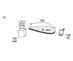
- FIG. 6 is a schematic diagram illustrating a wireless communication system according to an embodiment of the present invention.
- the wireless communication system 10 includes a base station 100 and a user device 200.
- the wireless communication system 10 is an LTE system or an LTE-Advanced (LTE-A) system, but is not limited thereto, and may be any wireless communication system that supports 3D MIMO communication.
- LTE-A LTE-Advanced
- the base station 100 realizes 3D MIMO communication with the user apparatus 200 and wirelessly connects to the user apparatus 200 via a plurality of antenna ports in a multidimensional antenna such as a mounted two-dimensional planar antenna or three-dimensional antenna. Specifically, the base station 100 receives a downlink (DL) packet received from a network device such as an upper station or a server that is communicatively connected on a core network (not shown) via a plurality of antenna ports. And an uplink (UL) packet received from the user apparatus 200 via a plurality of antenna ports is transmitted to the network apparatus.
- DL downlink
- a network device such as an upper station or a server that is communicatively connected on a core network (not shown) via a plurality of antenna ports.
- UL uplink
- the base station 100 typically includes a 3D MIMO antenna for transmitting and receiving radio signals to and from the user apparatus 200, a communication interface (such as an X2 interface) for communicating with the adjacent base station 100, and a core network A communication interface (such as an S1 interface) for communication and a hardware resource such as a processor and a circuit for processing a transmission / reception signal with the user apparatus 200 are configured.
- a communication interface such as an X2 interface
- a communication interface such as an S1 interface
- a hardware resource such as a processor and a circuit for processing a transmission / reception signal with the user apparatus 200 are configured.
- Each function and process of the base station 100 to be described later may be realized by a processor processing or executing data or a program stored in a memory device.
- the base station 100 is not limited to the hardware configuration described above, and may have any other appropriate hardware configuration. In general, a large number of base stations 100 are arranged to cover a service area of the wireless communication system 10.
- User apparatus 200 realizes 3D MIMO communication with base station 100 and transmits and receives radio signals such as various data signals and control signals to and from base station 100 via a plurality of antenna ports of base station 100.
- the user apparatus 200 estimates a channel state between each antenna port and feeds back the estimated channel state to the base station 100 as channel state information (CSI).
- CSI channel state information
- the base station 100 controls the beam transmitted from each antenna port based on the received channel state information.
- User apparatus 200 may typically be any appropriate information processing apparatus having a wireless communication function such as a smartphone, a mobile phone, a tablet, a mobile router, or a wearable terminal.
- the user apparatus 200 includes a CPU (Central Processing Unit) such as a processor, a memory apparatus such as a RAM (Random Access Memory) and a flash memory, a wireless communication apparatus for transmitting and receiving a radio signal to and from the base station 100, and the like.
- a CPU Central Processing Unit
- memory apparatus such as a RAM (Random Access Memory) and a flash memory
- wireless communication apparatus for transmitting and receiving a radio signal to and from the base station 100, and the like.
- each function and process of the user device 200 to be described later may be realized by the CPU processing or executing data or a program stored in the memory device.
- the user apparatus 200 is not limited to the hardware configuration described above, and may be configured by a circuit that realizes one or more of the processes described below.
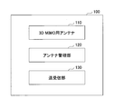
- FIG. 7 is a block diagram illustrating a configuration of a base station according to an embodiment of the present invention.
- the base station 100 includes a 3D MIMO antenna 110, an antenna management unit 120, and a transmission / reception unit 130.
- the antenna 110 for 3D MIMO is composed of a multidimensional antenna composed of a plurality of antenna elements, such as a two-dimensional planar antenna, a three-dimensional antenna such as a cylindrically arranged antenna or an antenna arranged on a cube surface. As shown in FIG. 3, the antenna 110 includes an antenna port including one or more antenna elements, and a beam transmitted from each antenna port is controlled to execute 3D MIMO communication with the user apparatus 200. .
- the antenna management unit 120 manages the antenna 110 and has antenna configuration information indicating the configuration of the antenna 110.
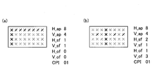
- the antenna configuration information may indicate the number of antenna ports in each dimension of the antenna 110 and the polarization type of the antenna 110.
- the antenna configuration information includes the number of antenna ports in the vertical direction (V_ap), the number of antenna ports in the horizontal direction (H_ap), and the polarization type (P_ap) of the antenna port indicating single polarization or orthogonal polarization. May be shown.
- the antenna configuration information is not limited to this.
- the antenna management unit 110 may index antenna ports based on each dimension of the antenna 110 and the polarization type.
- FIG. 8 is a diagram illustrating a specific example of antenna port indexing according to an embodiment of the present invention. For example, if the antenna 110 is a single polarization antenna, the antenna ports may be indexed first in the horizontal direction and then in the vertical direction, as shown in FIG. 8 (a). Similarly, although not shown, antenna ports may be indexed first in the vertical direction and then in the horizontal direction. Also, as shown in FIG. 8 (b), the antenna ports may be indexed independently with respect to the horizontal and vertical directions.
- the antenna port is first indexed with respect to the horizontal direction, then indexed with respect to the polarization direction, and then with respect to the vertical direction, as shown in FIG. It may be attached.
- the antenna ports may be indexed first with respect to the horizontal direction, then with respect to the vertical direction, and then with respect to the polarization direction.
- the antenna ports may also be indexed independently with respect to the horizontal direction, vertical direction and polarization direction.
- the antenna management unit 120 may further include reference signal configuration information indicating a signaling pattern of a reference signal transmitted from the antenna port of the antenna 110.
- the signaling pattern defines from which antenna port of the antenna 110 the reference signal is transmitted.
- the reference signal used by the user apparatus 200 to measure the channel state between each antenna port is transmitted from the base station 100 according to a predetermined signaling pattern.
- the antenna management unit 120 may have reference signal configuration information together with the antenna configuration information.
- the reference signal configuration information may indicate a sampling factor, an offset, and a polarization type in each dimension of the antenna 110 regarding the signaling pattern.
- the reference signal configuration information may indicate sampling factors (H_sf, V_sf) and offsets (H_of, V_of) in the horizontal direction and the vertical direction, respectively.
- the sampling factor may indicate a sampling interval in each dimension
- the offset may indicate a sampling start position from the origin in each dimension.
- the reference signal configuration information may have a cross polarization index (CPI).
- the cross polarization index indicates, for example, 00 when the reference signal is transmitted with two polarizations in the horizontal direction, and indicates 01 when the reference signal is transmitted with two polarizations in the vertical direction.
- the reference signal is configured to indicate 10, and 11 may be allocated for reserve.
- the reference signal configuration information may include a sampling factor (P_sf) in the polarization direction.
- FIG. 9 is a diagram showing a specific example of a reference signal transmission pattern according to an embodiment of the present invention.
- the transmission / reception unit 130 transmits / receives a radio signal to / from the user apparatus 200 via the antenna 110 and notifies the user apparatus 200 of antenna configuration information.
- the antenna configuration information indicates the configuration of the antenna 110, for example, the number of antenna ports in each dimension of the antenna 110 and the polarization type of the antenna 110.
- the transmission / reception unit 130 may notify the user apparatus 200 by combining the parameters indicating the number of antenna ports and the polarization type in each dimension. For example, the transmission / reception unit 130 combines the number of antenna ports (H_ap) in the horizontal direction and the polarization type (P_ap) and transmits it as joint information to the user apparatus 200, and uses the number of antenna ports (V_ap) in the vertical direction as additional information. You may transmit to the user apparatus 200. By transmitting parameters in this way, it becomes possible to maintain backward compatibility with previous releases of the LTE standard.
- the transceiver 130 may, for example, combine H_ap and V_ap and transmit P_ap as additional information, or combine V_ap and P_ap and use H_ap as additional information. You may send it.
- the polarization type indicating single polarization and dual polarization may be notified as a flag (P_flag).
- the transmission / reception unit 130 notifies the user apparatus 200 of antenna configuration information that defines the number of antenna ports in the horizontal direction and the number of antenna ports in the vertical direction.
- the transceiver 130 defines the number of antenna ports for the first CSI feedback set to be fed back to the user apparatus 200 and the number of antenna ports for the second CSI feedback set.
- the antenna configuration information may be notified to the user apparatus 200.
- the transmission / reception unit 130 notifies the user apparatus 200 of antenna configuration information related to the antenna port arrangement.
- the present invention is not limited to this. For example, the configuration of the antenna port, the antenna element, etc.
- the user apparatus 200 may be notified of the antenna configuration information related to the configuration, the TXRU configuration, the subarray configuration information, or any combination thereof.
- the transmission / reception unit 130 may notify the antenna configuration information by PBCH (Physical Broadcast Channel) or RRC (Radio Resource Control) signaling, or a combination thereof. For example, the total number of antenna ports may be notified by PBCH, and a detailed antenna configuration may be notified based on PBCH information.
- the transmission / reception unit 130 may notify the antenna configuration information by including it in a CSI process defined in Release 11 of the LTE standard.
- the CSI process includes a CSI-RS resource configuration and a CSI-IM (CSI-Interference Measurement) resource configuration, and the user apparatus 200 measures the channel state for each CSI process notified from the base station 100, and performs measurement. CSI is generated based on the channel state.
- the user apparatus 200 calculates power necessary to execute 3D MIMO communication based on the CSI-RS resource configuration, and interference power from other beams in the 3D MIMO communication based on the CSI-IM resource configuration. Is calculated.
- a plurality of CSI-RS resources may be included in one CSI process.
- the antenna configuration information may be included in the CSI-RS resource.
- a plurality of CSI processes (or CSI-RS resource configurations) may be included using a higher level concept of the CSI process.
- Rel. With 11 downlink CoMPs it is possible to estimate CSI of a plurality of cells with a maximum of 8 antennas that are geographically separated by using a plurality of CSI processes.
- 3D MIMO it is possible to estimate a CSI greater than 8 by setting a plurality of CSI processes for a base station having an antenna greater than 8.
- CoMP basically assumed CSI estimation of geographically distant cells, but in 3D MIMO, information indicating whether multiple CSI processes and CSI-RS resource configurations are geographically separated or identical. May be included.
- colocation information may be included in the CSI-RS resource configuration.
- multiple CSI processes may signal the physical relationship of the CSI-RS resource configuration.
- the transmission / reception unit 130 may further notify the user apparatus 200 of reference signal configuration information. That is, the transmission / reception unit 130 may notify the user apparatus 200 of reference signal configuration information indicating a signaling pattern of a reference signal transmitted from the antenna port of the antenna 110 in addition to the antenna configuration information.
- the reference signal configuration information indicates, for example, the sampling factor, offset, and polarization type in each dimension of the antenna 110 related to the signaling pattern, but is not limited to this, from which antenna port of the antenna 110 Any other appropriate parameter indicating which polarization type is used to transmit the reference signal may be included. For example, the number of reference signals transmitted in each dimension and the sampling factor may be notified.
- the antenna configuration information and the reference signal configuration information have been described as different information elements.
- the present invention is not limited to this, and the parameters of the antenna configuration information and the reference signal configuration are not limited thereto.
- the user device 200 may be notified of the information parameter as one information element. Based on the parameters described above, it is possible to select a codebook or maximum rank.
- the transmission / reception unit 130 may further notify a parameter related to the CSI-RS resource configuration.
- Parameters related to CSI-RS resource configuration include CSI-RS resource configuration identity, number of CSI-RS ports, CSI RS configuration, CSI RS subframe configuration, PDSCH transmission power when calculating CSI feedback information
- the assumption of the apparatus 200, the pseudo random number generation parameter, and various collocation information when the user apparatus 200 is set to the transmission mode 10 are listed.
- the transmission / reception unit 130 notifies these parameters by including a plurality of elements in one CSI-RS resource configuration, or by including a plurality of CSI-RS resource configurations in one CSI configuration. Also good.
- the CSI-RS resource configuration identity is an index of the CSI-RS resource configuration.
- the number of CSI-RS ports is the number of CSI-RS transmission antenna ports (such as 2, 4 or 8).
- the CSI-RS configuration indicates the multiplexed position (subcarrier number, symbol number) of CSI-RS within a subframe.
- CSI-RS subframe configuration I CSI-RS indicates temporal multiplexing position (transmission period, offset) of CSI-RS.
- PDSCH transmit power P C during CSI feedback information calculation, shows the power ratio between the CSI-RS and PDSCH.
- the pseudo random number sequence generation parameter n ID is a parameter for generating a CSI-RS sequence.
- the higher layer parameter qcl-CRS-Info-r11 is information for notifying which CRS the CSI-RS is co-located. Since CSI-RS is very sparse, frequency synchronization cannot be performed by itself, and frequency synchronization is performed using CRS. For this reason, it is necessary to notify which CRS the CSI-RS uses.
- FIG. 10 is a block diagram illustrating a configuration of a user apparatus according to an embodiment of the present invention.
- the user apparatus 200 includes a channel state information generation unit 210 and a channel state information feedback unit 220.
- the channel state information generation unit 210 measures the channel state of the antenna port based on the reference signal transmitted from the antenna port of the 3D MIMO antenna 110 of the base station 100, and generates channel state information based on the measured channel state. Specifically, the channel state information generation unit 210 receives a reference signal (CSI-RS) transmitted from the antenna port of the base station 100 and, based on the received reference signal, a channel between the channel state information generation unit 210 and the transmission source antenna port. The state is measured, and the channel state with the antenna port not transmitting the reference signal is also estimated based on the measured channel state.
- CSI-RS reference signal
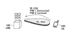
- the channel state information generation unit 210 calculates a rank indicator (RI), CQI (Channel Quality Indicator) and precoding matrix indicator (PMI) to be used for 3D MIMO communication based on the estimated channel state, Feedback is made to the base station 100 as state information (CSI).
- RI rank indicator
- CQI Channel Quality Indicator
- PMI precoding matrix indicator
- the channel state information generation unit 210 includes antenna configuration information indicating a configuration of the antenna 110 of the base station 100, reference signal configuration information indicating a signaling pattern of a reference signal transmitted from the antenna port of the antenna 110, and May be received from the base station 100, and the channel state of the antenna port may be measured based on the received antenna configuration information and reference signal configuration information.
- the channel state information generation unit 210 is configured to determine the antenna port that has not transmitted the reference signal based on the channel state measured for the antenna port that has transmitted the reference signal. Can be estimated with higher accuracy.
- the channel state information generation unit 210 may generate channel state information based on a plurality of CSI resources.
- PMI for 3D MIMO may be fed back based on two different CSI processes.
- RI and CQI may be fed back based on multiple CSI processes.
- Channel state information feedback section 220 feeds back the generated channel state information to base station 100 using different channel state information feedback means for antenna ports in each dimension of antenna 110.
- the base station 100 transmits the reference signal to the user apparatus 200 from the antenna port in each of the horizontal direction and the vertical direction. Therefore, as shown in FIG. 11, the channel state information feedback unit 220 also bases the horizontal PMI1 and the vertical PMI2 on the basis of the reference signals received from the antenna ports in the horizontal direction and the vertical direction, respectively. Feedback to station 100.
- the channel state information feedback unit 220 feeds back channel state information of RI, PMI, and CQI by various methods for CSI-RS1 and CSI-RS2. Also good. For example, as illustrated in FIG. 12A, the channel state information feedback unit 220 may feed back the RI, PMI, and CQI estimated for CSI-RS1 and CSI-RS2 to the base station 100 as joint information. Good. Also, as shown in FIG. 12B, the channel state information feedback unit 220 includes RI1, PMI1, and CQI1 estimated for CSI-RS1, and RI2, PMI2, and CQI2 estimated for CSI-RS2. May be fed back to base station 100 by separate channel state information feedback means. Similarly, as shown in FIG.
- the channel state information feedback unit 220 separately uses RI1 and PMI1 estimated for CSI-RS1 and RI2 and PMI2 estimated for CSI-RS2.
- the channel state information feedback means may feed back to the base station 100, and the CQI may be fed back to the base station 100 as joint information.
- the channel state information feedback unit 220 feeds back the generated channel state report information to the base station 100 using the first channel state information feedback unit for the antenna port in the horizontal direction of the antenna 110, and The generated channel state information may be fed back to the base station 100 using the second channel state information feedback means for the antenna port in the vertical direction of the first channel state information feedback means. It may be possible to make precoding finer than the means. In general, 3D MIMO is not suitable for multiplexing a plurality of data streams in the vertical direction, and control of only the vertical direction of the beam is mainly assumed, while finer beam control is effective in the horizontal direction. It is considered to be appropriate. In order to reduce the amount of signaling for feedback, channel state information feedback section 220 feeds back horizontal PMI1 and vertical PMI2 to base station 100 using two types of channel state information feedback means having different granularities. May be.
- the first channel state information feedback means may be a LTE standard release 12 4-Tx codebook
- the second channel state information feedback means may be a DFT (Discrete Fourier Transform) codebook.
- the DFT codebook is simpler than the LTE standard release 12 4-Tx codebook, and is suitable for realizing vertical beam control.
- the first channel state information feedback means is a LTE standard release 12 4-Tx codebook
- the second channel state information feedback means may be a beam index in beam selection instead of PMI. It may be feedback information when tracking is performed. That is, the channel state information feedback unit 220 selects an optimum beam among the beams transmitted from each antenna port of the base station 100, and sets the beam index of the selected beam to the base station 100 as second channel state information feedback means.
- the channel state information feedback unit 220 when receiving the CSI-RS process from the base station 100, notifies the beam index by beam tracking for the first CSI-RS process and notifies the selected PMI for the second CSI-RS process. May be.
- the channel state information feedback unit 220 may set channel state information feedback means for each CSI feedback unit, such as setting channel state information feedback means such as a code book for each CSI process.
- the channel state information feedback unit 220 may combine the rank indicators of each dimension of the antenna 110 and feed back to the base station 100. Specifically, the channel state information feedback unit 220 may notify the base station 100 of channel state information in the horizontal direction and the vertical direction as joint information. At this time, the selected horizontal PMI depends on the selected vertical PMI. For example, regarding the rank indicator, a plurality of RIs such as a first RI of the first PMI and a second RI of the second PMI may be fed back. For example, when the number of reception antennas of the user apparatus 200 is 4, the maximum rank is limited to 4.
- the channel state information feedback unit 220 may combine the rank in the horizontal direction and the rank in the vertical direction and feed back to the base station 100 by a combination of rank indicators as shown in FIG.
- the method of notifying the combined rank related to rank 4 is shown, but in addition to this, a combined rank extending over a plurality of ranks (for example, ranks 1 to 8) may be notified.
- a combination related to a relatively high (or multi-rank) vertical rank indicator is not included. May be better. That is, it may be advantageous to associate the rank indicator with only the horizontal CSI (or include it in the horizontal CSI feedback).
- a plurality of PMIs such as a first PMI in the horizontal direction and polarization type and a second PMI in the vertical direction may be fed back.
- the user apparatus 200 may use the latest RI and the first PMI to select the second PMI, and may use the latest RI and the second PMI to select the first PMI. Therefore, the base station 100 notifies the user apparatus 200 of the latest RI and the first PMI in order to select the second PMI, and notifies the user apparatus 200 of the latest RI and the second PMI in order to select the first PMI. May be.
- CQI may be selected for each CQI process. Also, one CQI may be selected based on two different CSI processes.
Abstract
Description
100 基地局
200 ユーザ装置
Claims (10)
- 3D MIMO(3-Dimensional Multiple-Input Multiple-Output)通信を実現する基地局であって、
3D MIMO用のアンテナと、
前記アンテナを管理するアンテナ管理部と、
前記アンテナを介しユーザ装置との間で無線信号を送受信する送受信部と、
を有し、
前記アンテナ管理部は、前記アンテナの構成を示すアンテナコンフィギュレーション情報を有し、
前記送受信部は、前記アンテナコンフィギュレーション情報を前記ユーザ装置に通知する基地局。 - 前記アンテナコンフィギュレーション情報は、前記アンテナの各次元におけるアンテナポート数と、前記アンテナの偏波種別とを示す、請求項1記載の基地局。
- 前記アンテナ管理部は、前記アンテナの各次元と偏波種別とに基づきアンテナポートをインデックス付けする、請求項2記載の基地局。
- 前記アンテナ管理部は更に、前記アンテナのアンテナポートから送信されるリファレンス信号のシグナリングパターンを示すリファレンス信号コンフィギュレーション情報を有し、
前記送受信部は更に、前記リファレンス信号コンフィギュレーション情報を前記ユーザ装置に通知する、請求項1乃至3何れか一項記載の基地局。 - 前記リファレンス信号コンフィギュレーション情報は、前記シグナリングパターンに関する前記アンテナの各次元におけるサンプリングファクタ、オフセット及び偏波種別を示す、請求項4記載の基地局。
- 3D MIMO(3-Dimensional Multiple-Input Multiple-Output)通信を実現するユーザ装置であって、
基地局の3D MIMO用のアンテナのアンテナポートから送信されたリファレンス信号により前記アンテナポートのチャネル状態を測定し、前記測定したチャネル状態に基づきチャネル状態情報を生成するチャネル状態情報生成部と、
前記アンテナの各次元におけるアンテナポートについて異なるチャネル状態情報フィードバック手段を用いて、前記生成されたチャネル状態情報を前記基地局にフィードバックするチャネル状態情報フィードバック部と、
を有するユーザ装置。 - 前記チャネル状態情報生成部は、前記基地局のアンテナの構成を示すアンテナコンフィギュレーション情報と前記アンテナのアンテナポートから送信されるリファレンス信号のシグナリングパターンを示すリファレンス信号コンフィギュレーション情報とを前記基地局から受信し、前記受信したアンテナコンフィギュレーション情報とリファレンス信号コンフィギュレーション情報とに基づき前記アンテナポートのチャネル状態を測定する、請求項6記載のユーザ装置。
- 前記チャネル状態情報フィードバック部は、前記アンテナの水平方向におけるアンテナポートについて第1チャネル状態情報フィードバック手段を用いて、前記生成されたチャネル状態報情報を前記基地局にフィードバックし、前記アンテナの垂直方向におけるアンテナポートについて第2チャネル状態情報フィードバック手段を用いて、前記生成されたチャネル状態情報を前記基地局にフィードバックし、
前記第1チャネル状態情報フィードバック手段は、前記第2チャネル状態情報フィードバック手段より精細なプリコーディングを可能にする、請求項6又は7記載のユーザ装置。 - 前記第1チャネル状態情報フィードバック手段は、LTE規格リリース12の4-Txコードブックであり、
前記第2チャネル状態情報フィードバック手段は、DFT(Discrete Fourier Transform)コードブックである、請求項8記載のユーザ装置。 - 前記チャネル状態情報フィードバック部は、前記アンテナの各次元のランクインジケータを結合して前記基地局にフィードバックする、請求項6乃至9何れか一項記載のユーザ装置。
Priority Applications (5)
| Application Number | Priority Date | Filing Date | Title |
|---|---|---|---|
| EP20171818.6A EP3709697A1 (en) | 2014-09-25 | 2015-09-15 | Base station and user equipment |
| EP15843330.0A EP3200497A4 (en) | 2014-09-25 | 2015-09-15 | Base station and user device |
| JP2016550120A JP6185188B2 (ja) | 2014-09-25 | 2015-09-15 | 基地局及びユーザ装置 |
| CN201580050535.2A CN107079308B (zh) | 2014-09-25 | 2015-09-15 | 基站和用户装置 |
| US15/507,771 US10804990B2 (en) | 2014-09-25 | 2015-09-15 | Base station and user equipment |
Applications Claiming Priority (2)
| Application Number | Priority Date | Filing Date | Title |
|---|---|---|---|
| JP2014195882 | 2014-09-25 | ||
| JP2014-195882 | 2014-09-25 |
Publications (1)
| Publication Number | Publication Date |
|---|---|
| WO2016047505A1 true WO2016047505A1 (ja) | 2016-03-31 |
Family
ID=55581032
Family Applications (1)
| Application Number | Title | Priority Date | Filing Date |
|---|---|---|---|
| PCT/JP2015/076172 WO2016047505A1 (ja) | 2014-09-25 | 2015-09-15 | 基地局及びユーザ装置 |
Country Status (5)
| Country | Link |
|---|---|
| US (1) | US10804990B2 (ja) |
| EP (2) | EP3709697A1 (ja) |
| JP (1) | JP6185188B2 (ja) |
| CN (1) | CN107079308B (ja) |
| WO (1) | WO2016047505A1 (ja) |
Cited By (5)
| Publication number | Priority date | Publication date | Assignee | Title |
|---|---|---|---|---|
| WO2016152301A1 (ja) * | 2015-03-24 | 2016-09-29 | ソニー株式会社 | 装置 |
| WO2016189990A1 (ja) * | 2015-05-25 | 2016-12-01 | ソニー株式会社 | 無線通信装置、端末装置及び方法 |
| WO2018083253A1 (en) * | 2016-11-04 | 2018-05-11 | Telefonaktiebolaget Lm Ericsson (Publ) | Methods and systems for beam tracking process management and indices |
| WO2018120803A1 (zh) * | 2016-12-28 | 2018-07-05 | 上海朗帛通信技术有限公司 | 一种被用于多天线传输的ue、基站中的方法和装置 |
| CN108390707A (zh) * | 2016-12-08 | 2018-08-10 | 上海朗帛通信技术有限公司 | 一种被用于多天线传输的ue、基站中的方法和装置 |
Families Citing this family (19)
| Publication number | Priority date | Publication date | Assignee | Title |
|---|---|---|---|---|
| WO2012125186A1 (en) * | 2011-03-15 | 2012-09-20 | Intel Corporation | Conformal phased array antenna with integrated transceiver |
| KR102357524B1 (ko) * | 2014-11-03 | 2022-02-04 | 삼성전자주식회사 | 풀-디멘젼 다중 입력 다중 출력 방식을 지원하는 통신 시스템에서 기준 신호 송/수신 장치 및 방법 |
| US10567057B2 (en) * | 2014-12-30 | 2020-02-18 | Lg Electronics Inc. | Method for performing channel estimation in wireless communication system and apparatus therefor |
| US10419095B2 (en) | 2015-01-05 | 2019-09-17 | Lg Electronics Inc. | Method for configuring channel state information using polarization characteristics of antenna in wireless communication system and device therefor |
| CN113708805A (zh) | 2015-03-31 | 2021-11-26 | 索尼公司 | 无线通信系统中的电子设备和无线通信方法 |
| CN106160823B (zh) * | 2015-04-03 | 2021-02-05 | 索尼公司 | 用于无线通信的装置和方法 |
| CN112491524B (zh) * | 2015-04-10 | 2024-02-23 | 阿里斯卡尔股份有限公司 | 发送csi-rs的基站和报告csi的用户设备 |
| US20190036574A1 (en) * | 2016-04-01 | 2019-01-31 | Intel IP Corporation | Csi feedback for open loop fd-mimo transmission |
| US10623072B2 (en) * | 2016-05-20 | 2020-04-14 | Telefonaktiebolaget Lm Ericsson (Publ) | Method for arbitrary antenna power pattern utilizing a multiple of antenna elements |
| CN110326228B (zh) | 2016-08-11 | 2023-06-13 | 交互数字专利控股公司 | 用于新无线电的csi反馈方法和装置 |
| KR20180098032A (ko) * | 2017-02-24 | 2018-09-03 | 삼성전자주식회사 | 무선 통신 시스템에서 기준 신호를 전송하기 위한 장치 및 방법 |
| WO2019148511A1 (en) * | 2018-02-05 | 2019-08-08 | Telefonaktiebolaget Lm Ericsson (Publ) | Method and devices for estimation of mimo channel state information |
| CN116073864A (zh) * | 2018-10-15 | 2023-05-05 | 华为技术有限公司 | 通信方法和通信装置 |
| CN113316909A (zh) * | 2018-12-05 | 2021-08-27 | 瑞典爱立信有限公司 | 用于获得ue特定的csi的可扩展方法 |
| US10804984B1 (en) * | 2019-06-05 | 2020-10-13 | Qualcomm Incorporated | Adaptive hybrid precoder selection in 2D antenna configuration |
| CN113746573B (zh) * | 2020-05-30 | 2023-01-06 | 华为技术有限公司 | 一种信道测量方法及装置 |
| CN113556156B (zh) * | 2020-06-03 | 2023-08-08 | 中兴通讯股份有限公司 | 3d-mimo天线及其参数确定方法、基站、电子设备和可读介质 |
| US11646506B2 (en) * | 2020-12-30 | 2023-05-09 | Qualcomm Incorporated | Techniques for beam-specific phase adjustment in non-co-located dual-polarized antenna arrays |
| CN114301551B (zh) * | 2021-12-30 | 2023-06-02 | 北京信息科技大学 | 一种车联网中基于感知的车载天线极化状态估计方法 |
Citations (3)
| Publication number | Priority date | Publication date | Assignee | Title |
|---|---|---|---|---|
| US20130308714A1 (en) * | 2012-05-17 | 2013-11-21 | Qualcomm Incorporated | Codebook and feedback design for high order mimo |
| US20130329664A1 (en) * | 2012-06-11 | 2013-12-12 | Samsung Electronics Co., Ltd. | Channel state information transmission/reception method and apparatus for use in wireless communication system |
| JP2014053811A (ja) * | 2012-09-07 | 2014-03-20 | Ntt Docomo Inc | 無線通信方法、ユーザ端末、無線基地局及び無線通信システム |
Family Cites Families (13)
| Publication number | Priority date | Publication date | Assignee | Title |
|---|---|---|---|---|
| US6889061B2 (en) * | 2000-01-27 | 2005-05-03 | Celletra Ltd. | System and method for providing polarization matching on a cellular communication forward link |
| US9252930B2 (en) * | 2011-01-07 | 2016-02-02 | Futurewei Technologies, Inc. | Reference signal transmission and reception method and equipment |
| US9794887B2 (en) * | 2011-09-30 | 2017-10-17 | Sharp Kabushiki Kaisha | Terminal apparatus, base station apparatus, method for terminal apparatus, and method for base station apparatus which can set appropriate uplink transmission power |
| CN103178882B (zh) * | 2011-12-23 | 2016-01-27 | 中国移动通信集团公司 | 一种3d mimo下倾角调整方法、装置及基站 |
| CN104115421B (zh) * | 2012-01-06 | 2017-05-31 | Lg电子株式会社 | 用于在无线接入系统中使用时分双工模式发送和接收信号的方法及其装置 |
| US8913682B2 (en) | 2012-05-18 | 2014-12-16 | Samsung Electronics Co., Ltd. | Apparatus and method for channel state information codeword construction for a cellular wireless communication system |
| US9225478B2 (en) * | 2012-07-02 | 2015-12-29 | Intel Corporation | Supporting measurments and feedback for 3D MIMO with data transmission optimization |
| JP6127146B2 (ja) * | 2012-09-28 | 2017-05-10 | インターデイジタル パテント ホールディングス インコーポレイテッド | 多次元アンテナ構成を使用する無線通信 |
| CN103716078B (zh) * | 2012-09-29 | 2019-03-12 | 中兴通讯股份有限公司 | 一种信道状态信息的处理方法及装置 |
| CN104604285B (zh) * | 2012-10-23 | 2019-02-15 | Lg电子株式会社 | 在无线通信系统中反馈信道状态信息的方法及其设备 |
| KR101978776B1 (ko) * | 2013-02-28 | 2019-05-16 | 삼성전자주식회사 | 다수의 안테나를 사용하는 이동통신 시스템에서 피드백 송수신 방법 및 장치 |
| JP6171484B2 (ja) | 2013-03-29 | 2017-08-02 | セイコーエプソン株式会社 | 画像記録装置 |
| US9967013B2 (en) * | 2014-01-29 | 2018-05-08 | Lg Electronics Inc. | Feedback reporting method for massive antenna array based beamforming in wireless communication system, and apparatus therefor |
-
2015
- 2015-09-15 WO PCT/JP2015/076172 patent/WO2016047505A1/ja active Application Filing
- 2015-09-15 CN CN201580050535.2A patent/CN107079308B/zh active Active
- 2015-09-15 EP EP20171818.6A patent/EP3709697A1/en active Pending
- 2015-09-15 JP JP2016550120A patent/JP6185188B2/ja active Active
- 2015-09-15 EP EP15843330.0A patent/EP3200497A4/en not_active Withdrawn
- 2015-09-15 US US15/507,771 patent/US10804990B2/en active Active
Patent Citations (3)
| Publication number | Priority date | Publication date | Assignee | Title |
|---|---|---|---|---|
| US20130308714A1 (en) * | 2012-05-17 | 2013-11-21 | Qualcomm Incorporated | Codebook and feedback design for high order mimo |
| US20130329664A1 (en) * | 2012-06-11 | 2013-12-12 | Samsung Electronics Co., Ltd. | Channel state information transmission/reception method and apparatus for use in wireless communication system |
| JP2014053811A (ja) * | 2012-09-07 | 2014-03-20 | Ntt Docomo Inc | 無線通信方法、ユーザ端末、無線基地局及び無線通信システム |
Non-Patent Citations (3)
| Title |
|---|
| FUJITSU: "Discussion on Feedback Design for LTE-A", RL-103221, 3GPP, 4 May 2010 (2010-05-04), XP050420258 * |
| QUALCOMM INCORPORATED: "Discussion on Simulation Assumptions for 3D Channel Model Calibration", RL-134621, 3GPP, 28 September 2013 (2013-09-28), XP008185266 * |
| See also references of EP3200497A4 * |
Cited By (21)
| Publication number | Priority date | Publication date | Assignee | Title |
|---|---|---|---|---|
| JPWO2016152301A1 (ja) * | 2015-03-24 | 2018-01-18 | ソニー株式会社 | 装置 |
| US10862550B2 (en) | 2015-03-24 | 2020-12-08 | Sony Corporation | Multiple-input multiple-output (MIMO) apparatus |
| US10630350B2 (en) | 2015-03-24 | 2020-04-21 | Sony Corporation | Multiple-input multiple-output (MIMO) apparatus |
| WO2016152301A1 (ja) * | 2015-03-24 | 2016-09-29 | ソニー株式会社 | 装置 |
| US10312975B2 (en) | 2015-03-24 | 2019-06-04 | Sony Corporation | Apparatus |
| US10530432B2 (en) | 2015-05-25 | 2020-01-07 | Sony Corporation | Wireless communication device, terminal device, and method |
| WO2016189990A1 (ja) * | 2015-05-25 | 2016-12-01 | ソニー株式会社 | 無線通信装置、端末装置及び方法 |
| US10998947B2 (en) | 2015-05-25 | 2021-05-04 | Sony Corporation | Wireless communication device, terminal device, and method |
| US11038570B2 (en) | 2016-11-04 | 2021-06-15 | Telefonaktiebolaget Lm Ericsson (Publ) | Methods and systems for beam tracking process management and indices |
| CN110140300A (zh) * | 2016-11-04 | 2019-08-16 | 瑞典爱立信有限公司 | 用于波束跟踪过程管理和索引的方法和系统 |
| KR20190073533A (ko) * | 2016-11-04 | 2019-06-26 | 텔레폰악티에볼라겟엘엠에릭슨(펍) | 빔 추적 프로세스 관리 및 인덱스를 위한 방법 및 시스템 |
| EP4160929A1 (en) * | 2016-11-04 | 2023-04-05 | Telefonaktiebolaget LM ERICSSON (PUBL) | Methods and systems for beam tracking process management and indices |
| KR102250565B1 (ko) | 2016-11-04 | 2021-05-10 | 텔레폰악티에볼라겟엘엠에릭슨(펍) | 빔 추적 프로세스 관리 및 인덱스를 위한 방법 및 시스템 |
| AU2017353516B2 (en) * | 2016-11-04 | 2020-07-02 | Telefonaktiebolaget Lm Ericsson (Publ) | Methods and systems for beam tracking process management and indices |
| WO2018083253A1 (en) * | 2016-11-04 | 2018-05-11 | Telefonaktiebolaget Lm Ericsson (Publ) | Methods and systems for beam tracking process management and indices |
| CN108390707A (zh) * | 2016-12-08 | 2018-08-10 | 上海朗帛通信技术有限公司 | 一种被用于多天线传输的ue、基站中的方法和装置 |
| US10951271B2 (en) | 2016-12-28 | 2021-03-16 | Shanghai Langbo Communication Technology Company Limited | Method and device for multi-antenna transmission in UE and base station |
| CN109617575B (zh) * | 2016-12-28 | 2020-06-30 | 上海朗帛通信技术有限公司 | 一种被用于多天线传输的ue、基站中的方法和装置 |
| CN109617575A (zh) * | 2016-12-28 | 2019-04-12 | 上海朗帛通信技术有限公司 | 一种被用于多天线传输的ue、基站中的方法和装置 |
| WO2018120803A1 (zh) * | 2016-12-28 | 2018-07-05 | 上海朗帛通信技术有限公司 | 一种被用于多天线传输的ue、基站中的方法和装置 |
| US11626904B2 (en) | 2016-12-28 | 2023-04-11 | Apex Beam Technologies Llc | Method and device for multi-antenna transmission in user equipment (UE) and base station |
Also Published As
| Publication number | Publication date |
|---|---|
| CN107079308A (zh) | 2017-08-18 |
| EP3709697A1 (en) | 2020-09-16 |
| EP3200497A4 (en) | 2017-09-27 |
| EP3200497A1 (en) | 2017-08-02 |
| JP6185188B2 (ja) | 2017-08-23 |
| US20170288758A1 (en) | 2017-10-05 |
| US10804990B2 (en) | 2020-10-13 |
| JPWO2016047505A1 (ja) | 2017-05-25 |
| CN107079308B (zh) | 2019-07-12 |
Similar Documents
| Publication | Publication Date | Title |
|---|---|---|
| JP6185188B2 (ja) | 基地局及びユーザ装置 | |
| US10389418B2 (en) | Beam selecting method, base station, and user equipment | |
| JP6594443B2 (ja) | 基地局及びプリコーディングマトリックス決定方法 | |
| JP6573610B2 (ja) | ユーザ装置および基地局 | |
| CN106464332B (zh) | 使用天线布置的波束形成 | |
| US20180115355A1 (en) | Beam selection method, mobile station and base station | |
| JP6997824B2 (ja) | ユーザ装置、無線通信方法及び基地局 | |
| JP2019176496A (ja) | ユーザ装置 | |
| CN109155766B (zh) | 非周期信号发送方法、基站和用户设备 | |
| JP2018538732A (ja) | 無線通信システム、無線基地局及びユーザ装置 | |
| WO2022066747A1 (en) | Device and method for performing csi reporting for type ii port selection codebook | |
| US10020855B2 (en) | User equipment and base station | |
| US20220069879A1 (en) | A Scalable Method for Obtaining UE-Specific CSI | |
| TW202312697A (zh) | 無線通訊系統中下行鏈路多天線傳輸方法 | |
| WO2022060825A1 (en) | Device and method for performing beamforming in angle-delay domains |
Legal Events
| Date | Code | Title | Description |
|---|---|---|---|
| 121 | Ep: the epo has been informed by wipo that ep was designated in this application |
Ref document number: 15843330 Country of ref document: EP Kind code of ref document: A1 |
|
| ENP | Entry into the national phase |
Ref document number: 2016550120 Country of ref document: JP Kind code of ref document: A |
|
| REEP | Request for entry into the european phase |
Ref document number: 2015843330 Country of ref document: EP |
|
| WWE | Wipo information: entry into national phase |
Ref document number: 2015843330 Country of ref document: EP |
|
| WWE | Wipo information: entry into national phase |
Ref document number: 15507771 Country of ref document: US |
|
| NENP | Non-entry into the national phase |
Ref country code: DE |