WO2016043143A1 - Appareil de prévention de retour d'écoulement - Google Patents
Appareil de prévention de retour d'écoulement Download PDFInfo
- Publication number
- WO2016043143A1 WO2016043143A1 PCT/JP2015/075941 JP2015075941W WO2016043143A1 WO 2016043143 A1 WO2016043143 A1 WO 2016043143A1 JP 2015075941 W JP2015075941 W JP 2015075941W WO 2016043143 A1 WO2016043143 A1 WO 2016043143A1
- Authority
- WO
- WIPO (PCT)
- Prior art keywords
- valve seat
- valve
- float
- check valve
- backflow prevention
- Prior art date
Links
Images


Classifications
-
- E—FIXED CONSTRUCTIONS
- E03—WATER SUPPLY; SEWERAGE
- E03F—SEWERS; CESSPOOLS
- E03F7/00—Other installations or implements for operating sewer systems, e.g. for preventing or indicating stoppage; Emptying cesspools
- E03F7/02—Shut-off devices
- E03F7/04—Valves for preventing return flow
-
- E—FIXED CONSTRUCTIONS
- E03—WATER SUPPLY; SEWERAGE
- E03F—SEWERS; CESSPOOLS
- E03F5/00—Sewerage structures
- E03F5/04—Gullies inlets, road sinks, floor drains with or without odour seals or sediment traps
- E03F5/0401—Gullies for use in roads or pavements
- E03F5/0405—Gullies for use in roads or pavements with an odour seal
-
- E—FIXED CONSTRUCTIONS
- E03—WATER SUPPLY; SEWERAGE
- E03F—SEWERS; CESSPOOLS
- E03F5/00—Sewerage structures
- E03F5/04—Gullies inlets, road sinks, floor drains with or without odour seals or sediment traps
- E03F5/042—Arrangements of means against overflow of water, backing-up from the drain
-
- F—MECHANICAL ENGINEERING; LIGHTING; HEATING; WEAPONS; BLASTING
- F16—ENGINEERING ELEMENTS AND UNITS; GENERAL MEASURES FOR PRODUCING AND MAINTAINING EFFECTIVE FUNCTIONING OF MACHINES OR INSTALLATIONS; THERMAL INSULATION IN GENERAL
- F16K—VALVES; TAPS; COCKS; ACTUATING-FLOATS; DEVICES FOR VENTING OR AERATING
- F16K15/00—Check valves
- F16K15/02—Check valves with guided rigid valve members
- F16K15/021—Check valves with guided rigid valve members the valve member being a movable body around which the medium flows when the valve is open
- F16K15/023—Check valves with guided rigid valve members the valve member being a movable body around which the medium flows when the valve is open the valve member consisting only of a predominantly disc-shaped flat element
-
- F—MECHANICAL ENGINEERING; LIGHTING; HEATING; WEAPONS; BLASTING
- F16—ENGINEERING ELEMENTS AND UNITS; GENERAL MEASURES FOR PRODUCING AND MAINTAINING EFFECTIVE FUNCTIONING OF MACHINES OR INSTALLATIONS; THERMAL INSULATION IN GENERAL
- F16K—VALVES; TAPS; COCKS; ACTUATING-FLOATS; DEVICES FOR VENTING OR AERATING
- F16K15/00—Check valves
- F16K15/02—Check valves with guided rigid valve members
- F16K15/06—Check valves with guided rigid valve members with guided stems
- F16K15/063—Check valves with guided rigid valve members with guided stems the valve being loaded by a spring
-
- F—MECHANICAL ENGINEERING; LIGHTING; HEATING; WEAPONS; BLASTING
- F16—ENGINEERING ELEMENTS AND UNITS; GENERAL MEASURES FOR PRODUCING AND MAINTAINING EFFECTIVE FUNCTIONING OF MACHINES OR INSTALLATIONS; THERMAL INSULATION IN GENERAL
- F16K—VALVES; TAPS; COCKS; ACTUATING-FLOATS; DEVICES FOR VENTING OR AERATING
- F16K17/00—Safety valves; Equalising valves, e.g. pressure relief valves
- F16K17/36—Safety valves; Equalising valves, e.g. pressure relief valves actuated in consequence of extraneous circumstances, e.g. shock, change of position
-
- F—MECHANICAL ENGINEERING; LIGHTING; HEATING; WEAPONS; BLASTING
- F16—ENGINEERING ELEMENTS AND UNITS; GENERAL MEASURES FOR PRODUCING AND MAINTAINING EFFECTIVE FUNCTIONING OF MACHINES OR INSTALLATIONS; THERMAL INSULATION IN GENERAL
- F16K—VALVES; TAPS; COCKS; ACTUATING-FLOATS; DEVICES FOR VENTING OR AERATING
- F16K31/00—Actuating devices; Operating means; Releasing devices
- F16K31/12—Actuating devices; Operating means; Releasing devices actuated by fluid
- F16K31/18—Actuating devices; Operating means; Releasing devices actuated by fluid actuated by a float
- F16K31/20—Actuating devices; Operating means; Releasing devices actuated by fluid actuated by a float actuating a lift valve
- F16K31/22—Actuating devices; Operating means; Releasing devices actuated by fluid actuated by a float actuating a lift valve with the float rigidly connected to the valve
-
- F—MECHANICAL ENGINEERING; LIGHTING; HEATING; WEAPONS; BLASTING
- F16—ENGINEERING ELEMENTS AND UNITS; GENERAL MEASURES FOR PRODUCING AND MAINTAINING EFFECTIVE FUNCTIONING OF MACHINES OR INSTALLATIONS; THERMAL INSULATION IN GENERAL
- F16K—VALVES; TAPS; COCKS; ACTUATING-FLOATS; DEVICES FOR VENTING OR AERATING
- F16K33/00—Floats for actuation of valves or other apparatus
-
- E—FIXED CONSTRUCTIONS
- E03—WATER SUPPLY; SEWERAGE
- E03C—DOMESTIC PLUMBING INSTALLATIONS FOR FRESH WATER OR WASTE WATER; SINKS
- E03C1/00—Domestic plumbing installations for fresh water or waste water; Sinks
- E03C1/12—Plumbing installations for waste water; Basins or fountains connected thereto; Sinks
- E03C1/28—Odour seals
- E03C1/298—Odour seals consisting only of non-return valve
-
- E—FIXED CONSTRUCTIONS
- E03—WATER SUPPLY; SEWERAGE
- E03F—SEWERS; CESSPOOLS
- E03F5/00—Sewerage structures
- E03F5/04—Gullies inlets, road sinks, floor drains with or without odour seals or sediment traps
- E03F2005/0416—Gullies inlets, road sinks, floor drains with or without odour seals or sediment traps with an odour seal
- E03F2005/0417—Gullies inlets, road sinks, floor drains with or without odour seals or sediment traps with an odour seal in the form of a valve
Definitions
- the present invention relates to a backflow prevention device disposed in a drainage system that discharges wastewater generated in a site such as a factory or in a building to a river, the sea, or a public drainage facility.
- a float type that prevents backflow to drain in the forward direction from upstream to downstream A backflow prevention valve is provided.
- a float type check valve is exemplified in Japanese Utility Model Publication No. 6-67588.
- the float type check valve includes an annular valve seat that communicates the upstream side and the downstream side of the drainage system, a float that is positioned below the annular valve seat, and a plurality of guide members that guide the float vertically. It has.
- the float floats and descends with the level of drainage to open and close the annular valve seat. Since the water level is low at normal times, the float descends and is placed (landed) on the bottom plate below the annular valve seat, and the annular valve seat is opened. Therefore, drainage is performed in the forward direction from the upstream to the downstream through the annular valve seat. On the other hand, since the water level rises at the time of reverse flow, the float is floated and the annular valve seat is closed. This prevents backflow (overflow) upstream from the annular valve seat.
- a plurality of buildings are connected to a single drainage system, and wastewater generated in each building is treated by a single drainage system. Therefore, a plurality of float-type backflow prevention valves are provided in the drainage system to prevent backflow into each building.
- the above-mentioned float type check valve controls the flow of drainage so as not to flow back, but cannot control the flow of air (gas). Since the annular valve seat is normally opened, air is freely movable on the drainage system. Therefore, gas generated in the drainage system of the drainage system may flow backward through the drainage system and flow into the building. In a drainage system to which a plurality of buildings are connected, when a fire occurs in one building, smoke from the fire may flow into the drainage system and flow into another building (backflow).
- This invention is to provide a backflow prevention device which aims to block the flow of gas while preventing the backflow of wastewater by a float.
- the backflow prevention device provided in the drainage system for draining from the upstream to the downstream provided by the present invention includes a check valve and a float type backflow prevention valve arranged in order from the upstream to the downstream of the drainage system. And.
- the check valve is located above the float type check valve, opens in the vertical direction, and communicates the upstream side of the drainage system and the float type check valve side, and below the valve seat
- the valve seat is closed by abutting against the valve seat by an upward biasing force, and is lowered against the biasing force by the head pressure of drainage water flowing in from the upstream side.
- a biasing member that biases the valve body upward.
- At least a member for closing the valve seat by the valve body including the valve seat, the valve body, and the biasing member is formed of metal.
- the float type check valve is opened in the vertical direction, and is positioned so as to be movable in the vertical direction below the annular valve seat, an annular valve seat that communicates the check valve side and the downstream side of the drainage system, As the water level of the drainage rises, the annular valve seat is closed by fitting the opening and closing the opening, and by opening the opening by lowering the water level of the drainage.
- the biasing member may be a coil spring.
- the movement of the gas on the upstream side and the downstream side of the drainage system is blocked by the check valve disposed upstream of the float type check valve, and at the time of back flow, the check valve is connected by the float type check valve. Is prevented.
- the wastewater generated upstream is discharged downstream via the check valve and float type check valve, preventing the backflow of wastewater and blocking gas movement while maintaining the drainage function. can do.
- valve body including at least the valve seat, the valve body and the urging member is made of metal
- the valve seat should be kept closed even in the event of a fire.
- the movement of the gas on the upstream side and the downstream side can be blocked more reliably.
- valve seat and the valve body are made of metal, the valve seat is not completely closed. It is possible to prevent the float from being damaged at the time of backflow, for example, from being deformed by vigorously contacting the annular valve seat. In the case where the backflow water is rushing at once, the air also flows back. Therefore, this air accumulates near the lower part of the check valve. Accordingly, the pressure on the downstream side of the check valve becomes higher than the pressure on the upstream side.
- the valve seat of the check valve is not completely closed, the air moves through the valve seat (opening) due to the pressure difference and moves from the downstream side to the upstream side. For this reason, the pressure on the downstream side of the check valve gradually decreases, and the water level during the reverse flow gradually increases. Along with this, the float gradually rises to close the annular valve seat.
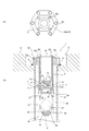
- (A) is a top view of the backflow prevention apparatus which concerns on Example 1 of this invention.
- (B) is sectional drawing of the backflow prevention apparatus which concerns on Example 1 of this invention. It is an expanded sectional view of a check valve included in the backflow prevention device. It is the figure which looked at the state which attached the annular valve seat and the valve seat retainer to the main body of the float type backflow prevention valve from the downstream side. It is a top view of the baseplate of a float type backflow prevention valve.
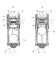
- (A) is explanatory drawing which shows the operation state of the backflow prevention apparatus in normal time.
- (B) is explanatory drawing which shows the operation state of the backflow prevention apparatus at the time of backflow. It is sectional drawing of the backflow prevention apparatus which concerns on Example 2 of this invention. It is sectional drawing of the backflow prevention apparatus which concerns on Example 3 of this invention.
- a backflow prevention device according to an embodiment of the present invention will be described with reference to the drawings.
- the configuration of the present invention is not limited to the embodiment.
- FIG. 1A is a plan view of a backflow prevention device according to Embodiment 1 of the present invention
- FIG. 1B is a cross-sectional view of the backflow prevention device 1.
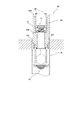
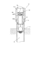
- FIG. 2 is an enlarged cross-sectional view of the check valve 10 included in the backflow prevention device 1.
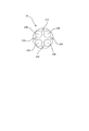
- 3 is a view of a state in which the annular valve seat 21 and the valve seat retainer 26 are attached to the main body 5 of the float type check valve 20 as viewed from the downstream side
- FIG. 4 is a bottom plate 23 of the float type check valve 20.
- FIG. 1A the floor surface 2 and the like are partially omitted.
- the backflow prevention device 1 of this embodiment is disposed in a drainage system that discharges drainage generated on the floor 2 of the building to a river or the sea. Prevent water from flowing back to the floor 2 from rivers. Moreover, the backflow prevention apparatus 1 interrupts
- the drainage system includes a recess H formed on the floor surface 2, a drain pipe 3 extending downward from the bottom surface of the recess H, and the like.
- the backflow prevention device 1 is disposed at the upper end portion of the drain pipe 3.
- the backflow prevention device 1 includes a main body 5, a disc type check valve (hereinafter referred to as a check valve) 10 attached to the main body 5, a float type check valve (hereinafter referred to as a backflow prevention valve) 20, and the like.
- the main body 5 has an inner stepped cylindrical shape having an upstream port 7 having a circular cross section penetrating in the vertical direction.
- the main body 5 has a flange 5A at the upper end.
- the flange 5A is fixed to the fixture 8 with a bolt B1.
- the fixture 8 is fixedly supported on the floor surface 2 (the bottom surface of the recess H) by welding 4.
- the check valve 10 includes a check valve body 11, a spring seat 12 disposed in the check valve body 11, a coil spring 13, a valve body 14, and the like.
- the check valve body 11 has an upstream opening 11A, a downstream opening 11B, and a valve chamber 11C that communicates with the openings 11A and 11B.
- the check valve main body 11 is sandwiched (fixed) between the inner surface stepped portion 5 ⁇ / b> B of the main body 5 and the check valve presser 18.
- the upstream opening portion 11A communicates the inside of the check valve retainer 18 with the communication opening 15A and the valve chamber 11C.
- the downstream opening portion 11B communicates the valve chamber 11C and the upstream port 7.
- the check valve presser 18 has a cylindrical shape penetrating in the vertical direction, and an upper end flange 18A is fixed to the flange 5A of the main body 5 by a bolt B2.
- An annular valve seat 15 is formed on the valve chamber 11C side of the upstream opening 11A.
- the annular valve seat 15 has a communication opening 15A, and communicates the upstream opening 11A and the valve chamber 11C through the communication opening 15A.
- a guide portion 16 is formed on the wall surface of the valve chamber 11C.
- the guide portion 16 is formed from the upstream opening portion 11A to the downstream opening portion 11B at four locations on the wall surface of the valve chamber 11C, and guides the movement of the valve body 14 in the vertical direction.
- the annular valve seat 15 and the guide portion 16 of this embodiment are integrally formed with the check valve main body 11, they may be formed separately.
- An O-ring 19 is disposed in a groove formed on the outer periphery of the check valve body 11.
- the O-ring 19 is a rubber ring, for example, and prevents drainage from leaking between the main body 5 and the check valve main body 11.
- the spring seat 12 has a disk shape and supports the coil spring 13 with the recess 12A.
- the inner diameter of the recess 12A is substantially the same as the outer diameter of the coil spring 13, and restricts the movement of the coil spring 13 in the horizontal direction.
- the spring seat 12 is supported by the guide portion 16 by fitting an end portion into a groove portion formed in the guide portion 16. Further, the rotation of the spring seat 12 is restricted by a turning screw (not shown).
- the coil spring 13 biases the valve body 14 upward. In the valve body 14, the protruding portion on the bottom surface of the disk shape is loosely fitted to the upper end of the coil spring 13 to open and close the annular valve seat 15. The opening / closing operation of the annular valve seat 15 by the valve body 14 will be described later.
- each member which comprises the non-return valve 10 of a present Example is metals, such as stainless steel, except for the O-ring 19.
- the backflow prevention valve 20 includes an annular valve seat 21 attached to the main body 5, four guide rods 22, a bottom plate 23 attached to the guide rod 22, and an inner side of the annular valve seat 21, the guide rod 22 and the bottom plate 23.
- positioned are provided.
- the backflow prevention valve 20 also includes a mesh basket 25.
- the annular valve seat 21 is made of rubber, for example, and has a communication opening 21A in the center.
- the annular valve seat 21 is pressed and fixed to the lower end of the main body 5 via a valve seat retainer 26 (see FIG. 3).
- the annular valve seat 21 communicates the upstream upstream port 7 and the downstream drainage pipe 3 via the communication opening 21A.
- the valve seat retainer 26 has an annular structure as shown in FIG.
- the valve seat retainer 26 has a small screw hole 26A for inserting a small screw 27 (see FIG. 1) for fixing the annular valve seat 21 and a screw hole 26B for inserting the guide rod 22.
- the valve seat retainer 26 is fixed to the main body 5 with a machine screw 27 as shown in FIG.
- the four guide rods 22 are made of metal such as stainless steel, and the upper ends thereof are screw-coupled to the small screw holes 26B provided at equal intervals on the lower end of the main body 5 and fixedly supported by the main body 5.
- the four guide bars 22 guide the float 24 in the vertical direction. It should be noted that at least three guide rods 22 need only be provided.
- the lower end portion of the guide rod 22 is screwed into the nut 28 while passing through the guide rod hole 23A (see FIG. 4) of the bottom plate 23.
- the bottom plate 23 is supported by the nut 28 so that the plate surface is horizontal, and is positioned below the float 24 to define the lower limit position of the movement of the float 24.
- the plate surface of the bottom plate 23 does not need to be precisely horizontally supported and may be substantially horizontal.
- the baseplate 23 has the several through-hole 23B for allowing waste_water
- the float 24 is made of a metal such as stainless steel and has a hollow spherical shape as shown in FIG.
- the float 24 is formed to have a lower specific gravity than the drainage, and moves (floats and descends) in the vertical direction between the annular valve seat 21 and the bottom plate 23 as the water level in the drainage pipe 3 changes.
- the float 24 is lowered, the float 24 is placed on the bottom plate 23 as shown in FIG.
- the float 24 opens and closes the annular valve seat 21 by rising and lowering.
- the mesh cage 25 is a wire mesh cage formed of a metal such as stainless steel, and accommodates dust contained in the drainage. Thereby, clogging in the drain pipe 3 is prevented.
- the net cage 25 is supported at the end by a guide bar 22 and a nut 28 in the same manner as the bottom plate 23.
- FIG. 5 (A) is an explanatory diagram showing the operating state of the backflow prevention device 1 when drainage flows from the upstream side during normal times
- FIG. 5 (B) shows the operating state of the backflow prevention device 1 during backflow. It is explanatory drawing which shows.
- valve body 14 of the check valve 10 comes into contact with the annular valve seat 15 by an urging force and closes the annular valve seat 15 as shown in FIG.
- the valve body 14 descends against the urging force by the head pressure of the drainage flowing into the check valve retainer 18 from the floor surface 2 or the like as shown in FIG. .
- the annular valve seat 15 is opened. Then, the waste water passes through the check valve presser 18 and the check valve 15 along the direction of the arrow in FIG.
- the float 24 of the backflow prevention valve 20 is lowered by its own weight or the like and is placed (landed) on the bottom plate 23 as shown in FIG. 1 (FIG. 5A), and the annular valve seat 21 Is opened. This is because the water level in the drain pipe 3 is generally lower than the arrangement position of the bottom plate 23. Therefore, the waste water that has flowed into the upstream port 7 through the check valve 10 flows to the downstream port 9 through the communication opening 21A, between the guide rods 22 and through the through hole 23B, and finally into the river or the like (downstream). Discharged.
- the valve body 14 of the check valve 10 abuts on the annular valve seat 15 by the urging force as shown in FIG. It remains as it is.
- the float 24 of the backflow prevention valve 20 rises from the downstream side toward the annular valve seat 21 because the water level in the drain pipe 3 rises, for example, by buoyancy or the like in a state where the lower half is submerged. Thereby, the float 24 will be in the state which closed the annular valve seat 21, as shown to FIG. 5 (B).
- the float 24 does not have to be a precise spherical shape, and may be a substantially spherical shape that can close the annular valve seat 21.
- the check valve 10 since the check valve 10 is closed except during draining as described above, gas movement between the upstream side and the downstream side of the check valve 10 is blocked. Therefore, it is possible to prevent the gas generated in the drainage basin of the drainage system from flowing into the building upstream of the check valve 10 (backflow). It is also possible to prevent smoke or the like generated by a fire or the like generated in the building from leaking into the drainage system and flowing into another building (backflow). Moreover, since the check valve 10 is made of metal, it does not melt even if a high temperature is reached due to a fire or the like. Therefore, the closed state of the valve seat can be maintained even in the event of a fire, and the movement of gas on the upstream side and the downstream side can be more reliably blocked.
- the annular valve seat 15 and the valve body 14 are made of metal, the annular valve seat 15 is not completely closed (sealed) by the valve body 14. As a result, it is possible to prevent the float 24 from being damaged at the time of backflow, for example, from being deformed by vigorously abutting against the annular valve seat 21. In the case where the backflow water is rushing at once, the air also flows back. Therefore, this air accumulates near the lower part of the check valve 10. Therefore, the pressure on the downstream side of the check valve 10 becomes higher than the pressure on the upstream side.
- Example 2 differs from Example 1 described above in the configuration in which the backflow prevention valve is provided between the two drain pipes. This different configuration will be described with reference to FIG. Since other configurations are the same as those of the first embodiment, description thereof is omitted.
- FIG. 6 is a cross-sectional view of the backflow prevention device 100 according to Embodiment 2 of the present invention.
- the main body 50 of the backflow prevention device 100 has a male screw 50A on a part of the outer periphery.
- the male screw 50 ⁇ / b> A is screwed with a female screw 30 ⁇ / b> A formed on a part of the inner periphery of the drain pipe 30, so that the backflow prevention device 100 is attached to the drain pipe 30.
- the check valve 10 is sandwiched between the check valve presser 180 and the inner surface stepped portion 50 ⁇ / b> B of the main body 50.
- an upper end flange 180A is fixed to the main body 50 by a bolt B3.
- an upstream drainage pipe (not shown) is connected to the upper end side of the main body 50 by screw coupling similarly to the drainage pipe 30.
- Example 1 differs from Example 1 described above in the configuration in which the backflow prevention device is provided between the two drain pipes. Moreover, the structure provided between two drain pipes using a fixture is different from the above-described second embodiment. This different configuration will be described with reference to FIG. Since other configurations are the same as those of the first embodiment, description thereof is omitted.
- FIG. 7 is a cross-sectional view of the backflow prevention device 101 according to Embodiment 3 of the present invention.
- the outer periphery of the upper end protruding from the drain pipe 31 is screw-coupled to the fixture 400.
- the fixture 400 has a substantially cylindrical shape, and a female screw 400 ⁇ / b> A provided on the inner periphery is screwed to a male screw 31 ⁇ / b> A provided on the outer periphery of the end of the drain pipe 31.
- the backflow prevention device 101 is attached to the drain pipe 31 via the fixture 400.
- the check valve 10 is sandwiched between the check valve presser 181 and the inner surface stepped portion 400 ⁇ / b> B of the fixture 400 so as to be connected to the upper end of the main body 51.
- the check valve presser 181 has an upper end flange 181A fixed by a screw B4.
- an upstream drain pipe (not shown) is screwed to the upper end of the fixture 400 so as to be externally fitted to the fixture 400.
- the check valve and the check valve are connected via the upstream port, but the present invention is not particularly limited to this.
- the check valve main body is fixed using a valve body presser, but is not particularly limited as long as it can be fixed.
- the check valve body may be fixed to the body by welding.
- the valve body is urged by using a single coil spring, but is not particularly limited as long as it can be urged upward.
- the valve body has a disc shape, but is not particularly limited thereto.
- the check valve may have a saddle shape in which a contact surface with the annular valve seat is a curved surface or a rectangular plate shape.
- the check valve is a lift type using a coil spring, but various types of check valves such as a swing type can be applied.
- the members constituting the check valve except for the O-ring are made of metal.
- at least the valve seat, the valve body, and the attachment are provided so that the valve seat can be kept closed even in the event of a fire.
- a member for closing the valve seat by the valve body including the biasing member may be formed of metal.
- the float and the bottom plate of the above-described embodiment are preferably made of metal in order to prevent mutual sticking. This is because the reverse flow itself does not occur frequently, and therefore the float is basically placed on the bottom plate, and when it is formed of resin or the like, it tends to adhere to the bottom plate.
- the bottom plate is used as the defining member for defining the lower limit position of the float.
- the lower limit position can be defined.
- it may be a saddle-shaped defining member having a recess where the float lands.
- This invention discharges wastewater generated in the grounds and buildings of factories to rivers, seas, public drainage facilities, etc., and drains water used in public baths, etc. It can be used in the industrial field where construction, sales and operation of drainage drainage systems are performed.
Landscapes
- Engineering & Computer Science (AREA)
- General Engineering & Computer Science (AREA)
- Mechanical Engineering (AREA)
- Health & Medical Sciences (AREA)
- Life Sciences & Earth Sciences (AREA)
- Hydrology & Water Resources (AREA)
- Public Health (AREA)
- Water Supply & Treatment (AREA)
- Check Valves (AREA)
- Sink And Installation For Waste Water (AREA)
- Self-Closing Valves And Venting Or Aerating Valves (AREA)
Abstract
Priority Applications (4)
| Application Number | Priority Date | Filing Date | Title |
|---|---|---|---|
| JP2015561448A JP5938151B1 (ja) | 2014-09-18 | 2015-09-14 | 逆流防止装置 |
| EP15842679.1A EP3196519B1 (fr) | 2014-09-18 | 2015-09-14 | Appareil de prévention de retour d'écoulement |
| ES15842679T ES2744609T3 (es) | 2014-09-18 | 2015-09-14 | Aparato de prevención de flujo de retorno |
| US15/459,922 US10072409B2 (en) | 2014-09-18 | 2017-03-15 | Backflow prevention apparatus |
Applications Claiming Priority (2)
| Application Number | Priority Date | Filing Date | Title |
|---|---|---|---|
| JP2014189680 | 2014-09-18 | ||
| JP2014-189680 | 2014-09-18 |
Related Child Applications (1)
| Application Number | Title | Priority Date | Filing Date |
|---|---|---|---|
| US15/459,922 Continuation US10072409B2 (en) | 2014-09-18 | 2017-03-15 | Backflow prevention apparatus |
Publications (1)
| Publication Number | Publication Date |
|---|---|
| WO2016043143A1 true WO2016043143A1 (fr) | 2016-03-24 |
Family
ID=55533181
Family Applications (1)
| Application Number | Title | Priority Date | Filing Date |
|---|---|---|---|
| PCT/JP2015/075941 WO2016043143A1 (fr) | 2014-09-18 | 2015-09-14 | Appareil de prévention de retour d'écoulement |
Country Status (5)
| Country | Link |
|---|---|
| US (1) | US10072409B2 (fr) |
| EP (1) | EP3196519B1 (fr) |
| JP (1) | JP5938151B1 (fr) |
| ES (1) | ES2744609T3 (fr) |
| WO (1) | WO2016043143A1 (fr) |
Cited By (3)
| Publication number | Priority date | Publication date | Assignee | Title |
|---|---|---|---|---|
| JP2017194068A (ja) * | 2016-04-18 | 2017-10-26 | 株式会社テイエルブイ | 逆流防止装置 |
| JP2020060254A (ja) * | 2018-10-10 | 2020-04-16 | 株式会社テイエルブイ | フロート式逆流防止弁 |
| CN114808683A (zh) * | 2022-07-01 | 2022-07-29 | 江苏润扬大桥发展有限责任公司 | 一种泄水通道阻断系统 |
Families Citing this family (4)
| Publication number | Priority date | Publication date | Assignee | Title |
|---|---|---|---|---|
| CN107975131B (zh) * | 2017-11-29 | 2019-11-05 | 宁波江北峰尚环保设备有限公司 | 一种地漏的施工安装方法 |
| US11591763B2 (en) | 2019-01-03 | 2023-02-28 | Ecoshore Int'l, Inc. | Systems and methods for coastal drainage control |
| CN111779120B (zh) * | 2020-08-11 | 2021-06-15 | 合肥江河建筑有限公司 | 一种路面排水结构及其施工方法 |
| US20240200701A1 (en) * | 2022-12-14 | 2024-06-20 | Gregory Reinhart | Check valve connector system |
Citations (4)
| Publication number | Priority date | Publication date | Assignee | Title |
|---|---|---|---|---|
| JPH0667588U (ja) * | 1993-02-26 | 1994-09-22 | 日産ディーゼル工業株式会社 | 排水逆流防止装置 |
| JPH1182771A (ja) * | 1997-09-12 | 1999-03-26 | Tlv Co Ltd | ばね付勢逆止弁 |
| JP2000240846A (ja) * | 1999-02-23 | 2000-09-08 | Kubota Corp | 空気弁 |
| JP2002524674A (ja) * | 1998-09-03 | 2002-08-06 | キム,ジョン,サン | 下水溝の逆流防止装置 |
Family Cites Families (10)
| Publication number | Priority date | Publication date | Assignee | Title |
|---|---|---|---|---|
| US3929155A (en) * | 1972-09-11 | 1975-12-30 | Owen L Garretson | Float shut off valve for liquefied petroleum gas tank fillers |
| US4917795A (en) * | 1986-10-15 | 1990-04-17 | Anthony Industries, Inc. | Automatic valve assembly |
| US5005603A (en) * | 1989-06-22 | 1991-04-09 | Amundson Eric K | Retrofittable sewer trap |
| US5842500A (en) * | 1997-08-04 | 1998-12-01 | Harsco Technologies Corporation | Overfill preventing valve |
| US6929023B2 (en) * | 2002-08-07 | 2005-08-16 | Polycheck Corporation | Back flow prevention device for pipelines conveying fluids |
| IL151748A0 (en) * | 2002-09-12 | 2003-04-10 | Aran Res & Dev Ltd | Fluid metering method and system |
| US20090139581A1 (en) * | 2005-04-11 | 2009-06-04 | Geoffrey Francis Herlihy | Vent valve |
| US20110030132A1 (en) * | 2009-08-10 | 2011-02-10 | Ladislau Biro | Multi-function cleanout plug and method of use |
| EP2685017A1 (fr) * | 2012-07-11 | 2014-01-15 | Planet Patent S.A. | Système de valve d'arrêt bidirectionnelle, ensemble de regard comprenant ledit système et utilisation de ce système dans un réseau d'égouts |
| US9927046B2 (en) * | 2015-06-25 | 2018-03-27 | Mueller International, Llc | Throttling device |
-
2015
- 2015-09-14 WO PCT/JP2015/075941 patent/WO2016043143A1/fr active Application Filing
- 2015-09-14 ES ES15842679T patent/ES2744609T3/es active Active
- 2015-09-14 EP EP15842679.1A patent/EP3196519B1/fr active Active
- 2015-09-14 JP JP2015561448A patent/JP5938151B1/ja active Active
-
2017
- 2017-03-15 US US15/459,922 patent/US10072409B2/en active Active
Patent Citations (4)
| Publication number | Priority date | Publication date | Assignee | Title |
|---|---|---|---|---|
| JPH0667588U (ja) * | 1993-02-26 | 1994-09-22 | 日産ディーゼル工業株式会社 | 排水逆流防止装置 |
| JPH1182771A (ja) * | 1997-09-12 | 1999-03-26 | Tlv Co Ltd | ばね付勢逆止弁 |
| JP2002524674A (ja) * | 1998-09-03 | 2002-08-06 | キム,ジョン,サン | 下水溝の逆流防止装置 |
| JP2000240846A (ja) * | 1999-02-23 | 2000-09-08 | Kubota Corp | 空気弁 |
Cited By (5)
| Publication number | Priority date | Publication date | Assignee | Title |
|---|---|---|---|---|
| JP2017194068A (ja) * | 2016-04-18 | 2017-10-26 | 株式会社テイエルブイ | 逆流防止装置 |
| JP2020060254A (ja) * | 2018-10-10 | 2020-04-16 | 株式会社テイエルブイ | フロート式逆流防止弁 |
| JP7181751B2 (ja) | 2018-10-10 | 2022-12-01 | 株式会社テイエルブイ | フロート式逆流防止弁 |
| CN114808683A (zh) * | 2022-07-01 | 2022-07-29 | 江苏润扬大桥发展有限责任公司 | 一种泄水通道阻断系统 |
| CN114808683B (zh) * | 2022-07-01 | 2022-09-20 | 江苏润扬大桥发展有限责任公司 | 一种泄水通道阻断系统 |
Also Published As
| Publication number | Publication date |
|---|---|
| ES2744609T3 (es) | 2020-02-25 |
| JPWO2016043143A1 (ja) | 2017-04-27 |
| EP3196519B1 (fr) | 2019-06-12 |
| US10072409B2 (en) | 2018-09-11 |
| JP5938151B1 (ja) | 2016-06-22 |
| US20170183860A1 (en) | 2017-06-29 |
| EP3196519A1 (fr) | 2017-07-26 |
| EP3196519A4 (fr) | 2018-04-18 |
Similar Documents
| Publication | Publication Date | Title |
|---|---|---|
| JP5938151B1 (ja) | 逆流防止装置 | |
| JP6396751B2 (ja) | 流量調整弁 | |
| JP6640009B2 (ja) | 逆流防止装置 | |
| JP6478636B2 (ja) | フロート式逆流防止弁 | |
| JP2013185386A (ja) | 床ドレンファンネル | |
| EP1167848B1 (fr) | Valve à flotteur avec deux entonnoirs | |
| JP6360761B2 (ja) | フロート式逆流防止弁 | |
| KR20190021150A (ko) | 저수조의 수질개선시스템 | |
| JP6040201B2 (ja) | 床ドレンファンネル | |
| JP6581428B2 (ja) | 田んぼダムシステム | |
| JP6293506B2 (ja) | フロート式逆流防止弁 | |
| JP2015224490A (ja) | フロート式逆流防止弁 | |
| JP2015206242A (ja) | フロート式逆流防止弁 | |
| JP6301190B2 (ja) | フロート式逆流防止弁 | |
| KR100884731B1 (ko) | 하수도용 공기밸브 | |
| JP2015218489A (ja) | フロート式逆流防止弁 | |
| JP7377528B2 (ja) | フロート式逆流防止弁 | |
| JP7152253B2 (ja) | フロート式逆止弁 | |
| JP7368844B2 (ja) | フロート式逆流防止弁 | |
| KR200297329Y1 (ko) | 급속 공기배출식 에어벤트 | |
| JP7405411B2 (ja) | フロート式逆流防止弁 | |
| JP7092640B2 (ja) | フロート式逆止弁 | |
| JP2024066010A (ja) | フロート式逆流防止弁 | |
| KR101111241B1 (ko) | 펌프 일체형 수문의 펌프 장착구조 | |
| JP2016089920A (ja) | 空気弁装置 |
Legal Events
| Date | Code | Title | Description |
|---|---|---|---|
| ENP | Entry into the national phase |
Ref document number: 2015561448 Country of ref document: JP Kind code of ref document: A |
|
| 121 | Ep: the epo has been informed by wipo that ep was designated in this application |
Ref document number: 15842679 Country of ref document: EP Kind code of ref document: A1 |
|
| NENP | Non-entry into the national phase |
Ref country code: DE |
|
| REEP | Request for entry into the european phase |
Ref document number: 2015842679 Country of ref document: EP |
|
| WWE | Wipo information: entry into national phase |
Ref document number: 2015842679 Country of ref document: EP |