WO2016039111A1 - Ensemble seringue, emballage pour ensemble seringue, bouchon d'étanchéité de cylindre extérieur et seringue préremplie - Google Patents
Ensemble seringue, emballage pour ensemble seringue, bouchon d'étanchéité de cylindre extérieur et seringue préremplie Download PDFInfo
- Publication number
- WO2016039111A1 WO2016039111A1 PCT/JP2015/073416 JP2015073416W WO2016039111A1 WO 2016039111 A1 WO2016039111 A1 WO 2016039111A1 JP 2015073416 W JP2015073416 W JP 2015073416W WO 2016039111 A1 WO2016039111 A1 WO 2016039111A1
- Authority
- WO
- WIPO (PCT)
- Prior art keywords
- puncture needle
- outer cylinder
- seal cap
- distal end
- syringe
- Prior art date
Links
Images


Classifications
-
- A—HUMAN NECESSITIES
- A61—MEDICAL OR VETERINARY SCIENCE; HYGIENE
- A61M—DEVICES FOR INTRODUCING MEDIA INTO, OR ONTO, THE BODY; DEVICES FOR TRANSDUCING BODY MEDIA OR FOR TAKING MEDIA FROM THE BODY; DEVICES FOR PRODUCING OR ENDING SLEEP OR STUPOR
- A61M5/00—Devices for bringing media into the body in a subcutaneous, intra-vascular or intramuscular way; Accessories therefor, e.g. filling or cleaning devices, arm-rests
- A61M5/178—Syringes
- A61M5/31—Details
- A61M5/32—Needles; Details of needles pertaining to their connection with syringe or hub; Accessories for bringing the needle into, or holding the needle on, the body; Devices for protection of needles
- A61M5/3202—Devices for protection of the needle before use, e.g. caps
-
- A—HUMAN NECESSITIES
- A61—MEDICAL OR VETERINARY SCIENCE; HYGIENE
- A61L—METHODS OR APPARATUS FOR STERILISING MATERIALS OR OBJECTS IN GENERAL; DISINFECTION, STERILISATION OR DEODORISATION OF AIR; CHEMICAL ASPECTS OF BANDAGES, DRESSINGS, ABSORBENT PADS OR SURGICAL ARTICLES; MATERIALS FOR BANDAGES, DRESSINGS, ABSORBENT PADS OR SURGICAL ARTICLES
- A61L31/00—Materials for other surgical articles, e.g. stents, stent-grafts, shunts, surgical drapes, guide wires, materials for adhesion prevention, occluding devices, surgical gloves, tissue fixation devices
- A61L31/04—Macromolecular materials
- A61L31/048—Macromolecular materials obtained by reactions only involving carbon-to-carbon unsaturated bonds
-
- A—HUMAN NECESSITIES
- A61—MEDICAL OR VETERINARY SCIENCE; HYGIENE
- A61L—METHODS OR APPARATUS FOR STERILISING MATERIALS OR OBJECTS IN GENERAL; DISINFECTION, STERILISATION OR DEODORISATION OF AIR; CHEMICAL ASPECTS OF BANDAGES, DRESSINGS, ABSORBENT PADS OR SURGICAL ARTICLES; MATERIALS FOR BANDAGES, DRESSINGS, ABSORBENT PADS OR SURGICAL ARTICLES
- A61L31/00—Materials for other surgical articles, e.g. stents, stent-grafts, shunts, surgical drapes, guide wires, materials for adhesion prevention, occluding devices, surgical gloves, tissue fixation devices
- A61L31/08—Materials for coatings
- A61L31/10—Macromolecular materials
-
- A—HUMAN NECESSITIES
- A61—MEDICAL OR VETERINARY SCIENCE; HYGIENE
- A61M—DEVICES FOR INTRODUCING MEDIA INTO, OR ONTO, THE BODY; DEVICES FOR TRANSDUCING BODY MEDIA OR FOR TAKING MEDIA FROM THE BODY; DEVICES FOR PRODUCING OR ENDING SLEEP OR STUPOR
- A61M5/00—Devices for bringing media into the body in a subcutaneous, intra-vascular or intramuscular way; Accessories therefor, e.g. filling or cleaning devices, arm-rests
- A61M5/002—Packages specially adapted therefor, e.g. for syringes or needles, kits for diabetics
-
- A—HUMAN NECESSITIES
- A61—MEDICAL OR VETERINARY SCIENCE; HYGIENE
- A61M—DEVICES FOR INTRODUCING MEDIA INTO, OR ONTO, THE BODY; DEVICES FOR TRANSDUCING BODY MEDIA OR FOR TAKING MEDIA FROM THE BODY; DEVICES FOR PRODUCING OR ENDING SLEEP OR STUPOR
- A61M5/00—Devices for bringing media into the body in a subcutaneous, intra-vascular or intramuscular way; Accessories therefor, e.g. filling or cleaning devices, arm-rests
- A61M5/008—Racks for supporting syringes or needles
-
- A—HUMAN NECESSITIES
- A61—MEDICAL OR VETERINARY SCIENCE; HYGIENE
- A61M—DEVICES FOR INTRODUCING MEDIA INTO, OR ONTO, THE BODY; DEVICES FOR TRANSDUCING BODY MEDIA OR FOR TAKING MEDIA FROM THE BODY; DEVICES FOR PRODUCING OR ENDING SLEEP OR STUPOR
- A61M5/00—Devices for bringing media into the body in a subcutaneous, intra-vascular or intramuscular way; Accessories therefor, e.g. filling or cleaning devices, arm-rests
- A61M5/178—Syringes
- A61M5/28—Syringe ampoules or carpules, i.e. ampoules or carpules provided with a needle
-
- A—HUMAN NECESSITIES
- A61—MEDICAL OR VETERINARY SCIENCE; HYGIENE
- A61M—DEVICES FOR INTRODUCING MEDIA INTO, OR ONTO, THE BODY; DEVICES FOR TRANSDUCING BODY MEDIA OR FOR TAKING MEDIA FROM THE BODY; DEVICES FOR PRODUCING OR ENDING SLEEP OR STUPOR
- A61M5/00—Devices for bringing media into the body in a subcutaneous, intra-vascular or intramuscular way; Accessories therefor, e.g. filling or cleaning devices, arm-rests
- A61M5/178—Syringes
- A61M5/31—Details
- A61M5/32—Needles; Details of needles pertaining to their connection with syringe or hub; Accessories for bringing the needle into, or holding the needle on, the body; Devices for protection of needles
-
- B—PERFORMING OPERATIONS; TRANSPORTING
- B65—CONVEYING; PACKING; STORING; HANDLING THIN OR FILAMENTARY MATERIAL
- B65D—CONTAINERS FOR STORAGE OR TRANSPORT OF ARTICLES OR MATERIALS, e.g. BAGS, BARRELS, BOTTLES, BOXES, CANS, CARTONS, CRATES, DRUMS, JARS, TANKS, HOPPERS, FORWARDING CONTAINERS; ACCESSORIES, CLOSURES, OR FITTINGS THEREFOR; PACKAGING ELEMENTS; PACKAGES
- B65D25/00—Details of other kinds or types of rigid or semi-rigid containers
- B65D25/02—Internal fittings
- B65D25/10—Devices to locate articles in containers
- B65D25/108—Devices, e.g. plates, presenting apertures through which the articles project
-
- B—PERFORMING OPERATIONS; TRANSPORTING
- B65—CONVEYING; PACKING; STORING; HANDLING THIN OR FILAMENTARY MATERIAL
- B65D—CONTAINERS FOR STORAGE OR TRANSPORT OF ARTICLES OR MATERIALS, e.g. BAGS, BARRELS, BOTTLES, BOXES, CANS, CARTONS, CRATES, DRUMS, JARS, TANKS, HOPPERS, FORWARDING CONTAINERS; ACCESSORIES, CLOSURES, OR FITTINGS THEREFOR; PACKAGING ELEMENTS; PACKAGES
- B65D43/00—Lids or covers for rigid or semi-rigid containers
- B65D43/02—Removable lids or covers
- B65D43/0202—Removable lids or covers without integral tamper element
-
- B—PERFORMING OPERATIONS; TRANSPORTING
- B65—CONVEYING; PACKING; STORING; HANDLING THIN OR FILAMENTARY MATERIAL
- B65D—CONTAINERS FOR STORAGE OR TRANSPORT OF ARTICLES OR MATERIALS, e.g. BAGS, BARRELS, BOTTLES, BOXES, CANS, CARTONS, CRATES, DRUMS, JARS, TANKS, HOPPERS, FORWARDING CONTAINERS; ACCESSORIES, CLOSURES, OR FITTINGS THEREFOR; PACKAGING ELEMENTS; PACKAGES
- B65D77/00—Packages formed by enclosing articles or materials in preformed containers, e.g. boxes, cartons, sacks or bags
- B65D77/10—Container closures formed after filling
- B65D77/20—Container closures formed after filling by applying separate lids or covers, i.e. flexible membrane or foil-like covers
-
- B—PERFORMING OPERATIONS; TRANSPORTING
- B65—CONVEYING; PACKING; STORING; HANDLING THIN OR FILAMENTARY MATERIAL
- B65D—CONTAINERS FOR STORAGE OR TRANSPORT OF ARTICLES OR MATERIALS, e.g. BAGS, BARRELS, BOTTLES, BOXES, CANS, CARTONS, CRATES, DRUMS, JARS, TANKS, HOPPERS, FORWARDING CONTAINERS; ACCESSORIES, CLOSURES, OR FITTINGS THEREFOR; PACKAGING ELEMENTS; PACKAGES
- B65D2543/00—Lids or covers essentially for box-like containers
- B65D2543/00009—Details of lids or covers for rigid or semi-rigid containers
- B65D2543/00444—Contact between the container and the lid
- B65D2543/00481—Contact between the container and the lid on the inside or the outside of the container
- B65D2543/00537—Contact between the container and the lid on the inside or the outside of the container on the outside, or a part turned to the outside of the mouth of the container
Definitions
- a syringe with a puncture needle fixed to the distal end portion of an outer cylinder is used as a syringe for administering a small amount of medicine such as an insulin syringe.
- a syringe for administering a small amount of medicine such as an insulin syringe.
- a small amount of medicine such as an insulin syringe.
- seal caps that can be sealed with a needle tip, for example, Japanese Patent Application Publication No. 2010-534546 (Patent Document 1) and US Pat. No. 6,719,732 (Patent Document 2) have been proposed.
- the seal cap (shield 10) of Patent Document 1 covers the end of a syringe (a part of which is shown in FIG. 2 of Patent Document 1).
- the distal end of the syringe 3 includes a hub 2 to which the needle 6 is fixed.
- the shield 10 has an open proximal end 11, a closed distal end 12, and a wall 13 that extends from the proximal end 11 to the closed distal end 12.
- the inner surface 14 of the wall 13 defines a cavity 15 that houses a portion of the distal end of the syringe 3.
- a portion 14a of the inner surface 14 is in contact with the hub 2 at the distal end of the syringe 3. It has become.
- FIG. 3 of patent document 1 some 14a of the inner surface 14 of the wall 13 is provided with the some groove
- FIG. The grooves 16 are regularly arranged along the periphery of the portion 14 a and they are parallel to the longitudinal axis A of the shield 10. They allow air to flow during assembly of the shield on the hub 2.
- the sticky surface of the shield is smaller, thus facilitating assembly and having the respective longitudinal axes A and B (see FIG. 2) of both the shield 10 and the injection device 3 to maintain confounding. It becomes easy. Therefore, the shield 10 of the present invention is completely and accurately fixed to the tip of the injection device 3.
- the groove formed by the characteristic roughness in the part 14 a of the inner surface 14 of the wall 13 makes it easier to remove the shield 10 from the tip of the injection device 3 when the injection device 3 is in use.
- a seal cap (device for protecting a syringe needle) of Patent Document 2 is an elastic needle cap that extends in the longitudinal direction between an open base end 22 and a closed end 24 as shown in FIGS. 20 has an inner housing 26 delimited by lateral walls 28 and end walls 30. Further, an annular bead 70 is formed between the first and second portions 40 and 42 of the housing 26 so as to expand inwardly at the end of the second portion 42 toward the proximal end 22. (Rib) is provided. In order to improve the deformability of the annular bead 70 and to facilitate the passage of pressurized steam, the bead 70 is provided with four slots 72 extending in the longitudinal direction.
- Patent Document 1 since the inner surface of the seal cap (shield 10) and the outer surface of the tip of the outer cylinder are in direct contact with each other, when the shield 10 is stored while attached to the outer cylinder, the shield 10 is attached to the outer cylinder. There was a risk of sticking. Furthermore, when sterilization with pressure load such as high-pressure steam sterilization or ethylene oxide gas sterilization is performed, the shield 10 is pressed against the outer cylinder, so that the inner surface of the shield 10 and the outer surface of the tip of the outer cylinder are in direct contact with each other. There is a possibility that the area of the shield 10 is increased and the shield 10 is easily stuck to the outer cylinder.
- pressure load such as high-pressure steam sterilization or ethylene oxide gas sterilization
- an annular bead 70 is formed on the inner surface of a seal cap (elastic needle cap 20) so as to expand inward, and the bead 70 has four slots extending in the longitudinal direction. 72 is provided.
- the inner surface of the elastic needle cap 20 and the outer surface of the tip of the outer cylinder are in close contact with each other. If the elastic needle cap 20 is stored while being attached to the outer cylinder, the elastic needle cap 20 may stick to the outer cylinder. It was. Further, when sterilization with pressure load such as high-pressure steam sterilization or ethylene oxide gas sterilization is performed, the elastic needle cap 20 is pressed against the outer cylinder, so that the inner surface of the elastic needle cap 20 and the outer surface of the tip of the outer cylinder are separated. There is a possibility that the area that is in direct contact is increased and the elastic needle cap 20 is likely to stick to the outer cylinder.
- an object of the present invention is to sterilize with a pressure load such as high-pressure steam sterilization or ethylene oxide gas sterilization as a method for sterilizing a syringe assembly with a seal cap attached to the outer cylinder while the seal cap is attached. Even when selected, there is no sticking between the inner surface of the seal cap and the outer surface of the distal end portion of the outer cylinder, and the outer cylinder seal cap and the syringe equipped with the outer cylinder seal cap that do not cause a cap removal failure Assembly, a prefilled syringe using a syringe assembly equipped with a seal cap for an outer cylinder, and a packaging body in which a plurality of syringe assemblies are stored.
- a pressure load such as high-pressure steam sterilization or ethylene oxide gas sterilization
- a syringe assembly comprising an outer cylinder having a fixed puncture needle and a seal cap attached to the outer cylinder, wherein the seal cap includes a closing tip, an opening proximal end, and the opening
- a puncture needle mounting portion storage portion that is positioned on the distal end side from the proximal end portion and stores the distal end portion of the puncture needle mounting portion, and a puncture needle storage portion that is continuous with the distal end of the puncture needle mounting portion storage portion and stores the puncture needle
- a hollow portion having a puncture needle tip of the puncture needle housed in the puncture needle housing portion, and a pierceable portion into which the puncture needle tip can be inserted.
- a cylindrical puncture needle mounting portion provided on an outer cylinder main body, a distal end of the outer cylinder main body, and having an annular head and an annular recess formed at a proximal end of the annular head;
- a closing tip an opening proximal end, a puncture needle attaching portion containing the puncture needle attaching portion located on the distal side of the opening proximal end, and a distal end of the puncture needle attaching portion containing the puncture needle attaching portion;
- a hollow portion having a puncture needle storage portion for storing a puncture needle, a pierceable portion where the puncture needle tip of the puncture needle stored in the puncture needle storage portion can be inserted, and the puncture needle mounting portion A protrusion formed on the inner surface of the storage portion, and the inner surface of the puncture needle mounting portion storage portion has a A laxylylene film is formed, and when the seal cap is attached to the outer cylinder, the puncture needle tip is inserted into the insertable portion of the seal cap, and the protruding portion and the annular shape
- An outer cylinder seal cap in which an inner surface of the puncture needle mounting portion storage portion and an outer surface of the puncture needle mounting portion are in close contact with each other through the polypara
- a syringe assembly package containing a plurality of the above-described syringe assemblies, wherein the package has a container body having an open top surface and shape retention, and a plurality of the syringe assemblies.
- the package body is provided with a ventilation part which is provided in the container body or the lid member and has a germ-impermeable and sterilizing gas flow, and is sterilized under high pressure steam or ethylene oxide gas. .
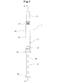
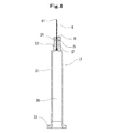
- FIG. 1 is a front view of a prefilled syringe according to an embodiment of the present invention.
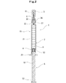
- 2 is a cross-sectional view taken along line AA in FIG.
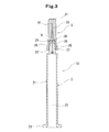
- FIG. 3 is an enlarged cross-sectional view of the syringe assembly of the present invention used in the prefilled syringe of FIGS. 1 and 2.
- FIG. 4 is an enlarged front view of the outer cylinder seal cap of the present invention used in the prefilled syringe of FIGS. 1 and 2 and the syringe assembly of FIG. 3.
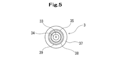
- FIG. 5 is a bottom view of the outer cylinder seal cap shown in FIG. 4.
- 6 is an enlarged sectional view taken along line BB in FIG.
- FIG. 7 is a front view of an outer cylinder used in the prefilled syringe of FIGS. 1 and 2 and the syringe assembly of FIG.
- FIG. 8 is an enlarged sectional view taken along the line CC of FIG. 9 is a perspective view of the outer cylinder shown in FIG.
- FIG. 10 is an explanatory diagram for explaining the operation of the outer cylinder seal cap of the present invention.
- FIG. 11 is a perspective view of the assembly package for a syringe of the present invention.
- FIG. 12 is an explanatory diagram for describing an internal configuration of the assembly assembly package for a syringe illustrated in FIG. 11.
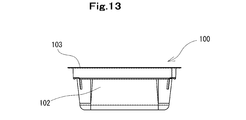
- FIG. 13 is a front view of the syringe assembly package shown in FIG. 11.
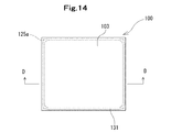
- FIG. 14 is a plan view of the syringe assembly package shown in FIG. 13.
- FIG. 15 is an enlarged sectional view taken along line DD of FIG.
- the prefilled syringe 1 of the present invention includes a syringe assembly 10, a gasket 4 that is housed in the syringe assembly 10 and that can be liquid-tightly slid within the syringe assembly 10, and the syringe assembly 10. It consists of the medicine 8 filled in the space formed by the gasket 4.
- the syringe assembly (in other words, an outer cylinder with a puncture needle attached with a cap) 10 according to the present invention includes an outer cylinder 2 and a seal cap 3 attached to the outer cylinder 2.
- the outer cylinder 2 has an outer cylinder main body portion 21, a cylindrical puncture needle attachment portion 22 provided at the distal end portion of the outer cylinder main body portion 21, and a puncture needle tip 61 at the distal end.
- a puncture needle 6 having a proximal end inserted and fixed thereto.
- the seal cap 3 includes a closed distal end portion 31, an opening proximal end portion 32, a puncture needle attachment portion accommodating portion 35 that is located on the distal end side of the opening proximal end portion 32 and accommodates the distal end portion of the puncture needle attachment portion 22, and puncture
- a hollow portion 30 that is continuous with the tip of the needle attachment portion storage portion 35 and has a puncture needle storage portion 34 that stores the puncture needle 6 and a puncture needle tip 61 of the puncture needle 6 stored in the puncture needle storage portion 34 are provided.
- a pierceable portion 33 that can be inserted.
- a polyparaxylylene coating is provided on the inner surface of the puncture needle mounting portion storage portion 35 of the seal cap 3.
- the polyparaxylylene coating may be provided on the outer surface of the puncture needle mounting portion 22 of the outer cylinder 2 instead of the inner surface of the puncture needle mounting portion storage portion 35 of the seal cap 3.
- the polyparaxylylene coating may be spread on both the inner surface of the puncture needle attachment portion storage portion 35 and the outer surface of the puncture needle attachment portion 22 of the outer cylinder 2.
- the prefilled syringe 1 includes a syringe assembly 10 including an outer tube 2 and a seal cap 3 attached to the outer tube 2 so as to seal the needle tip of the puncture needle, A gasket 4 housed in the syringe assembly 10 and slidable in a liquid-tight manner in the syringe assembly 10, and a medicine 8 filled in a space formed by the syringe assembly 10 and the gasket 4; And a plunger 5 attached to the gasket 4 or attached at the time of use.
- the medicine 8 is filled in a space formed by the outer cylinder 2, the gasket 4, and the seal cap 3.
- the medicine 8 to be filled may be any one, for example, high-concentration sodium chloride injection, minerals, heparin sodium aqueous solution, nitroglycerin, isosorbide nitrate, cyclosporine, benzodiazepines, antibiotics, vitamins ( Multivitamin preparations), various amino acids, antithrombotic agents such as heparin, insulin, antitumor agents, analgesics, cardiotonic agents, intravenous anesthetics, antiparkinson agents, ulcer treatment agents, corticosteroid agents, arrhythmia agents, correction Any electrolyte, antiviral agent, immunostimulant, etc. may be used.
- the outer cylinder 2 is provided at an outer cylinder main body 21, a cylindrical (hollow) puncture needle mounting portion 22 provided at the distal end of the outer cylinder main body 21, and a proximal end portion of the outer cylinder main body 21.
- a puncture needle 6 having a proximal end portion inserted into and fixed to the puncture needle mounting portion 22.
- the puncture needle 6 has a puncture needle tip 61 at the tip. The proximal end portion of the puncture needle 6 is inserted and fixed in the hollow portion of the puncture needle mounting portion 22, and the inside of the puncture needle 6 communicates with the internal space 20 of the outer cylinder 2.
- the puncture needle 6 may be inserted into a hollow portion of the puncture needle mounting portion 22 of the outer cylinder 2 formed in advance and fixed to the puncture needle mounting portion 22 with an adhesive, heat welding, or the like.
- the puncture needle 6 may be fixed directly to the outer cylinder 2 by insert molding.
- insert molding by molding the outer cylinder 2, the puncture needle mounting portion 22 becomes a tubular shape (hollow shape) into which the puncture needle 6 is inserted, and the puncture needle 6 has a proximal end portion at the puncture needle mounting portion. 22 is inserted into the hollow portion and fixed.
- the outer cylinder 2 is transparent or translucent.
- the outer cylinder main body 21 is a substantially cylindrical part that accommodates the gasket 4 in a liquid-tight and slidable manner.
- the puncture needle mounting portion 22 protrudes forward from the distal end portion (shoulder portion) of the outer cylinder main body portion and has a hollow cylindrical shape having a smaller diameter than the outer cylinder main body portion. Further, as shown in FIGS. 7 and 8, the puncture needle mounting portion 22 is provided at the distal end of the annular head portion 24 and the proximal end of the annular head portion 24, and is reduced in diameter toward the proximal end direction.
- the annular head portion 24 is formed with a recess 26 that is recessed from the distal end surface toward the proximal end side, and a hollow conical portion that is located in the recess 26 and has a vertex on the distal end side.
- a plurality of grooves extending in the axial direction of the outer cylinder 2 are formed on the outer surface of the connecting portion 27.
- annular recess is not tapered and may have a shape that is simply reduced in diameter so that a step is formed with the base end of the annular head 24.
- the connecting portion 27 may be omitted, and the proximal end portion of the annular recess (tapered reduced diameter portion 25) and the distal end portion of the outer cylinder main body portion 21 may be directly connected.
- the annular head portion 24 may have a hollow columnar shape (cylindrical shape) in which the recess 26 and the conical portion are omitted.
- Examples of the material for forming the outer cylinder 2 include polypropylene, polyethylene, polystyrene, polyamide, polycarbonate, polyvinyl chloride, poly- (4-methylpentene-1), acrylic resin, acrylonitrile-butadiene-styrene copolymer, polyethylene terephthalate.
- Various resins such as polyesters, cyclic olefin polymers, cyclic olefin copolymers, etc. are mentioned.
- polypropylene and cyclic polyolefins are easy to mold and heat resistant.
- As the puncture needle 6, a hollow one having a puncture needle tip 61 at the tip is used.
- a material for forming the puncture needle 6 a metal is generally used. Stainless steel is preferred as the metal.
- the gasket 4 includes a main body portion extending at substantially the same outer diameter, and a plurality of annular ribs provided in the main body portion (in this embodiment, if two, two or more, As long as the liquid-tightness and the slidability can be satisfied, the number may be set as appropriate. Further, the tip surface of the gasket 4 has a shape corresponding to the shape of the inner surface of the distal end of the outer cylinder 2 so as not to form a gap as much as possible between the two when contacting the inner surface of the distal end of the outer cylinder 2.
- the material for forming the gasket 4 includes elastic rubber (eg, isoprene rubber, butyl rubber, latex rubber, silicone rubber), synthetic resin (eg, styrene elastomer such as SBS elastomer and SEBS elastomer, ethylene- ⁇ olefin copolymer) It is preferable to use an olefin-based elastomer such as a combined elastomer.
- elastic rubber eg, isoprene rubber, butyl rubber, latex rubber, silicone rubber
- synthetic resin eg, styrene elastomer such as SBS elastomer and SEBS elastomer, ethylene- ⁇ olefin copolymer
- an olefin-based elastomer such as a combined elastomer.
- the gasket 4 is provided with a recess extending inward from the base end portion, and this recess has a female screw shape and is formed on the outer surface of the protruding portion 52 formed at the distal end portion of the plunger 5. It can be screwed with the male thread.
- the plunger 5 is not detached from the gasket 4 by screwing them together.
- the plunger 5 may be removed and attached at the time of use.
- the plunger 5 includes a protruding portion 52 that protrudes in a cylindrical shape forward from the disk portion at the tip, and an external thread that is screwed into the recessed portion of the gasket 4 is formed on the outer surface of the protruding portion.
- the plunger 5 includes a main body 51 extending in the axial direction having a cross-shaped cross section, and a pressing disk 53 provided at the base end.
- the outer cylinder seal cap 3 of the present invention is provided with an outer cylinder main body 21 and an annular recess formed at the distal end of the outer cylinder main body 21 and formed at the proximal end of the annular head 24 and the annular head 24. And a puncture needle attachment portion 22 having a puncture needle tip 61 at the tip, and a puncture needle 6 having a proximal end portion inserted and fixed to the puncture needle attachment portion 22. It is installed and used.
- the seal cap 3 includes a closed distal end portion 31, an opening proximal end portion 32, a puncture needle attachment portion storage portion 35 for storing the puncture needle attachment portion 22, and a puncture needle storage portion 34 continuous to the puncture needle attachment portion storage portion 35.
- a puncture needle attachment portion storage portion 35 for storing the puncture needle attachment portion 22
- a puncture needle storage portion 34 continuous to the puncture needle attachment portion storage portion 35.
- a protrusion 36 is formed on the inner surface of the puncture needle attachment portion storage portion 35 to suppress the sticking of the outer cylinder 2 to the puncture needle attachment portion 22.
- the puncture needle tip 61 is inserted and sealed in the pierceable portion 33 of the seal cap 3, and the protrusion 36 and The annular recess 25 of the puncture needle attachment portion 22 of the outer cylinder 2 is engaged, and the inner surface of the puncture needle attachment portion storage portion 35 and the outer surface of the puncture needle attachment portion 22 are in close contact via the polyparaxylylene coating 9. It will be in the state.
- the seal cap 3 is provided with a protruding portion 36 provided on the inner surface located on the distal end side of the predetermined length from the opening base end portion 32.
- the protruding portion 36 has a most protruding vertex portion 36a, and an inclined portion (tapered portion) 36b extending from the vertex portion 36a in the distal direction and gradually decreasing in the protruding height in the distal direction.
- the projecting portion 36 is an annular projecting portion
- the inclined portion 36b is a tapered portion in which the inner diameter of the puncture needle mounting portion accommodating portion 35 is reduced in the distal direction.
- the inner diameter of the puncture needle mounting portion storage portion 35 at the apex portion 36a is slightly smaller than the outer diameter of the distal end portion of the annular recess 25 of the puncture needle mounting portion 22 of the outer cylinder 2.
- the inner diameter of the puncture needle mounting portion storage portion 35 at least in the vicinity of the proximal end portion of the distal side inclined portion 36b is slightly smaller than the outer diameter of the annular head portion 24 of the puncture needle mounting portion 22 of the outer cylinder 2. .
- the distal end side inclined portion 36 b is pressed against the outer surface of the annular head portion 24 via the polyparaxylylene coating 9 and is in close contact therewith.
- the unintentional detachment of the seal cap 3 from the outer cylinder 2 is reduced.
- the inner diameter of the puncture needle mounting portion storage portion 35 at the tip of the tip side inclined portion is slightly smaller than the outer diameter of the annular head 24 of the puncture needle mounting portion 22 of the outer cylinder 2. It has become. For this reason, when the seal cap 3 is attached to the puncture needle mounting portion 22 of the outer cylinder 2, the tip-side inclined portion 36 b is entirely disposed on the outer surface of the annular head 24 via the polyparaxylylene coating 9. It is pressed and brought into close contact.
- the protruding portion 36 is formed in an annular shape along the inner surface of the puncture needle mounting portion storage portion 35. For this reason, compared with the case where the protrusion part 36 is intermittently formed in the inner surface of the puncture needle attachment part accommodating part 35, it presses and adheres to the outer surface of the cyclic
- the protrusion part 36 may be intermittently formed in the inner surface of the puncture needle attachment part accommodating part 35. FIG.
- the protrusion 36 further extends from the apex 36a toward the opening end (base end), and the protrusion height gradually decreases toward the opening end (base end). It has a base end side inclined portion 36c.
- the projecting portion 36 is an annular projecting portion
- the proximal-side inclined portion 36c is a proximal end side in which the inner diameter of the puncture needle mounting portion storage portion 35 increases in the proximal direction. It is a tapered part.
- the base end side inclined portion (base end side tapered portion) 36c is shorter and has a larger taper angle than the front end side inclined portion (tip end side tapered portion) 36b. It has become.
- the puncture needle mounting portion storage portion 35 has a predetermined length (specifically, the puncture needle storage portion 34) from the distal end portion of the distal end side inclined portion 36b of the protruding portion 36 toward the distal end direction.
- a straight line portion 36d extending to the base end portion.
- the inner diameter of the puncture needle mounting portion storage portion 35 in the straight portion 36d is constant and slightly smaller than the outer diameter of the annular head portion 24 of the puncture needle mounting portion 22 of the outer cylinder 2.
- the linear portion 36 d is pressed against the outer surface of the annular head portion 24 through the polyparaxylylene coating 9 and is in close contact therewith. It becomes.
- the inner diameter of the puncture needle mounting portion storage portion 35 in the straight portion 36d may be larger than the outer diameter of the annular head portion 24 of the puncture needle mounting portion 22 of the outer cylinder 2.
- the straight portion 36d may be omitted, and the distal side inclined portion 36b may be extended to the proximal end portion of the puncture needle storage portion 34.
- the separation resistance of the seal cap 3 from the outer cylinder 2 is preferably 1.5N to 20N, and particularly preferably 5 to 8N. Thereby, the seal cap 3 can be easily detached from the outer cylinder 2 when the prefilled syringe 1 is used while preventing the seal cap 3 from being unintentionally detached from the outer cylinder 2.
- the inclination angle (taper angle) of the tip side inclined portion 36b of the protruding portion 36 of the seal cap 3 is preferably 1 to 10 degrees, and particularly preferably 1 to 6 degrees.
- the protrusion height of the apex portion of the protrusion 36 is preferably 0.1 to 0.5 mm, and particularly preferably 0.05 to 0.25 mm.
- the proximal end portion of the distal side inclined portion 36b of the protruding portion 36 of the seal cap 3 is located around the annular recess 24 of the puncture needle mounting portion 22 of the outer cylinder 2, and the distal side inclined portion 36b.
- the inner diameter of the puncture needle mounting portion storage portion 35 at least in the vicinity of the proximal end portion is slightly smaller than the outer diameter of the annular recess 24. Therefore, the tip side inclined portion 36 b of the protruding portion 36 of the seal cap 3 is pressed against the outer surface of the annular recess 25 via the polyparaxylylene coating 9 and is in close contact therewith. Thereby, the unintentional detachment
- the annular recess 25 is formed at a proximal end of the annular head 24 and is formed of a tapered reduced diameter portion that decreases in diameter toward the proximal direction.
- the hollow portion 30 is formed from the opening proximal end portion 32 of the seal cap 3 to the proximal end of the puncture needle attachment portion accommodating portion 35 (projecting portion 36), and has substantially the same inner diameter.
- An extending puncture needle mounting portion introducing portion 38 is provided.
- the puncture needle attachment portion introducing portion 38 has an inner diameter slightly larger than the maximum inner diameter of the puncture needle attachment portion storage portion 35 and is slightly larger than the outer diameter of the annular head 24 of the puncture needle attachment portion 22 of the outer cylinder 2. It has become a thing. For this reason, it functions as an introduction portion of the puncture needle attachment portion 22 when the seal cap 3 is attached to the puncture needle attachment portion 22 of the outer cylinder 2.
- the puncture needle attachment portion introducing portion 38 has an annular standing surface 39 that stands up toward the opening proximal end portion 32 at the boundary with the proximal end of the puncture needle attachment portion accommodating portion 35 (projecting portion 36). Yes. Therefore, when the distal end portion of the outer cylinder 2 is inserted into the puncture needle attachment portion introduction portion 38 of the seal cap 3, the puncture needle attachment portion 22 of the outer cylinder 2 enters the puncture needle attachment portion introduction portion 38. Thereafter, as shown in FIG. 10, the annular tip surface of the annular head 24 of the puncture needle mounting portion 22 comes into contact with the annular standing surface 39. In this state, the puncture needle 6 is attached to the seal cap 3. Is substantially parallel to the central axis of the puncture needle, and enters into the small-diameter tip portion 34a of the puncture needle storage portion 34.
- the puncture needle attachment portion introduction portion functions as an introduction portion of the puncture needle attachment portion 22 if at least the inner diameter of the base end portion is larger than the outer diameter of the annular head portion 24 of the puncture needle attachment portion 22 of the outer cylinder 2. For this reason, unlike the embodiment described above, the inner diameter of the puncture needle attachment portion introduction portion may be reduced toward the distal direction. Further, the annular upright surface 39 may be omitted from the puncture needle attachment portion introduction portion, and the inner diameter of the puncture needle attachment portion introduction portion may be reduced toward the proximal end of the puncture needle attachment storage portion 35 (projecting portion 36). Good.
- the puncture needle attachment portion 22 When the annular distal end surface of the annular head 24 of the puncture needle attachment portion 22 enters the boundary between the proximal end of the puncture needle attachment portion storage portion 35 (projecting portion 36) and the puncture needle attachment portion introduction portion, the puncture is performed.
- the needle 6 is substantially parallel to the central axis of the seal cap 3 and enters the small diameter distal end portion 34a of the puncture needle storage portion 34.
- the puncture needle storage portion 34 has a proximal end located at the distal end of the straight portion 36d of the puncture needle attachment portion storage portion 35, and the inner diameter abruptly decreases toward the distal end. ing. Further, the proximal end portion of the puncture needle storage portion 34 is a curved annular surface that curves inward, thereby preventing the puncture needle 6 from being inserted and ensuring guidance to the distal end.
- the main body portion (central portion) of the puncture needle storage portion is a tapered portion that decreases in diameter toward the distal end, and has an inner diameter slightly larger than the outer diameter of the puncture needle 6 at the distal end, and has substantially the same inner diameter. A small-diameter tip 34a extending in the direction is formed.
- the puncture needle mounting portion 22 of the outer cylinder 2 is inserted into the seal cap, and the annular tip surface of the annular head 24 of the puncture needle mounting portion 22 is The puncture needle tip 61 of the puncture needle 6 enters the small-diameter distal end portion 34a of the puncture needle storage portion 34 in a state where it abuts on the annular upright surface 39 of the puncture needle attachment portion introduction portion 38 of the seal cap 3. And it is comprised so that the insertion possible part 33 may not be reached.
- the pierceable portion 33 is located in front of the puncture needle attachment portion introduction portion 38 (front end side), more precisely, in front of the small-diameter tip portion 34a of the puncture needle storage portion 34 and on the extension line.
- the shape of the puncture needle storage part 34 is not particularly limited as long as the puncture needle 6 can be stored, and may be, for example, a simple cylinder.
- a gripping flange 37 is formed on the base end of the seal cap 3 so as to project outwardly in an annular shape, and the flange 37 is provided with an annular recess 71.
- the position of the distal end side of the flange 37 is located on the distal end side from the annular standing surface 39 of the hollow portion 30 and is near the apex portion 36a of the protrusion 36 (in the case shown in FIG. 32 side).
- the insertable portion 33 is formed of an elastic material into which the puncture needle can be inserted.
- the elastic material into which the puncture needle can be inserted thermoplastic elastomers, for example, styrene elastomers such as SBS elastomer and SEBS elastomer, and olefin elastomers such as ethylene- ⁇ olefin copolymer elastomer are preferable.
- the elastic material may be rubber such as butyl rubber, isoprene rubber, latex rubber, or silicone rubber.
- the puncture needle mounting portion storage portion 35 and the pierceable portion 33 are made of the elastic material that can be inserted into the puncture needle. It has been formed. For this reason, when the seal cap 3 is attached to the puncture needle attachment portion 22 of the outer cylinder 2, the inner surface of the puncture needle attachment portion storage portion 35 is elastically matched with the outer surface of the annular head 24 of the puncture needle attachment portion 22. Deform.
- the seal cap 3 only the insertable portion 33 or the vicinity thereof may be formed of the elastic material into which the puncture needle can be inserted, and the outside thereof may be formed of a hard or semi-hard material.
- the material for forming the outer portion of the seal cap include polypropylene, polyethylene, polystyrene, polyamide, polycarbonate, polyvinyl chloride, poly- (4-methylpentene-1), acrylic resin, acrylonitrile-butadiene-styrene copolymer, Various resins such as polyesters such as polyethylene terephthalate and cyclic polyolefins may be mentioned.
- the seal cap at least the puncture needle mounting portion storage portion and the pierceable portion are formed of the elastic material that can be inserted into the puncture needle, and at least a part of the outer side is formed of the hard or semi-rigid material described above. You may cover with the formed cover member.
- a polyparaxylylene coating 9 that suppresses sticking to the outer surface of the puncture needle attachment portion 22 of the outer cylinder 2 is formed on at least the inner surface of the puncture needle attachment portion storage portion 35 of the seal cap 3.
- the polyparaxylylene coating 9 may be formed not only on the entire inner surface of the puncture needle attachment portion storage portion 35 but only on the portion that is in close contact with the outer surface of the puncture needle attachment portion 22.
- the present invention is particularly effective when the seal cap 3 is formed of a thermoplastic elastomer and the outer cylinder 2 is formed of a cyclic polyolefin.
- the polyparaxylylene coating 9 is formed on the entire inner surface of the puncture needle storage portion 34. For this reason, even if the puncture needle tip 61 of the puncture needle 6 comes into contact with the inner surface of the puncture needle storage portion 34, it does not stick. Thus, when the seal cap 3 is attached to the puncture needle mounting portion 22 of the outer cylinder 2, the puncture needle tip 61 of the puncture needle 6 that has entered the puncture needle storage portion 34 is placed on the inner surface of the puncture needle storage portion 34. Without sticking, it is guided to the distal end (small diameter distal end portion 34a) of the puncture needle storage portion 34 and is reliably inserted into the insertable portion 33.
- the puncture needle attachment portion 22 is formed on the puncture needle attachment portion introduction portion 38.
- the seal cap 3 can be smoothly attached to the puncture needle mounting portion 22 of the outer cylinder 2.
- the seal cap 3 is attached to the distal end portion (puncture needle mounting portion 22) of the outer cylinder 2, and the puncture needle tip of the puncture needle 6 is provided.
- 61 is inserted into the insertable portion 33 of the seal cap 3, is sealed in a liquid-tight state, and is formed on the annular recess 25 of the puncture needle attachment portion 22 and the inner surface of the puncture needle attachment portion storage portion 35.
- 36 is engaged, and the inner surface of the puncture needle attachment portion storage portion 35 and the outer surface of the puncture needle attachment portion 22 are in close contact via the polyparaxylylene coating 9.
- the inner surface of the puncture needle mounting portion storage portion 35 and the outer surface of the puncture needle mounting portion 22 are in close contact via the polyparaxylylene coating 9. Even when stored with the seal cap 3 attached thereto and when sterilization with pressure load such as high-pressure steam sterilization or ethylene oxide gas sterilization is performed, the inner surface of the puncture needle mounting portion storage portion 35 and the puncture needle mounting portion 22 Sticking to the outer surface can be suppressed.
- the inner surface of the puncture needle mounting portion storage portion 35 and the outer surface of the puncture needle mounting portion 22 are in close contact via the polyparaxylylene coating 9, the outer cylinder 2, even when sterilization with pressure load such as high-pressure steam sterilization or ethylene oxide gas sterilization is performed, the inner surface of the puncture needle mounting portion storage portion 35 and the puncture needle mounting portion 22 are stored. It is possible to suppress sticking to the outer surface.
- the polyparaxylylene coating 9 is formed on the inner surface of the puncture needle mounting portion storage portion 35.
- the present invention is not limited to this, and the polyparaxylylene coating is an outer cylinder. It may be formed on the outer surface of the puncture needle mounting portion.
- the polyparaxylylene coating may be formed on both the inner surface of the puncture needle attachment portion storage portion and the outer surface of the puncture needle attachment portion.
- polyparaxylylene those represented by the following chemical formula can be preferably used.
- the polyparaxylylene used in the present invention may be any of poly (paraxylylene) whose functional group is not substituted on the aromatic ring, and any functional group introduced into the aromatic ring or methylene group.
- poly (chloroparaxylylene) having an aromatic ring substituted with chlorine polymethylparaxylylene having an aromatic ring substituted with a methyl group
- polyfluoroparaxylylene having a methylene group substituted with fluorine etc.
- it may be a copolymer of not only a homopolymer composed of the above polyparaxylylene alone but also a monomer copolymerizable with a paraxylylene monomer.
- poly (paraxylylene) and poly (chloroparaxylylene) whose aromatic ring is not substituted with a functional group.
- the polyparaxylylene coating 9 may be formed of a single layer of the polyparaxylylene or copolymer, or may be formed of a multilayer of the polyparaxylylene and / or copolymer.
- polyparaxylylene does not indicate only poly (paraxylylene) in which an aromatic ring is not substituted with a functional group, but means one represented by the above chemical formula 1.
- the polyparaxylylene used in the present invention is formed by polymerization of a paraxylylene monomer obtained by thermally decomposing this paraxylylene dimer using the paraxylylene dimer represented by the above chemical formula 1 as a raw material. It is preferable that it is a laminated film. If it is such, it will become a thing with a stable film thickness, without a pinhole generating as a film.
- the thickness of the polyparaxylylene in the polyparaxylylene coating is preferably 1 ⁇ m to 10 ⁇ m, and particularly preferably 2 ⁇ m to 8 ⁇ m.
- the film made of polyparaxylylene is preferably formed by polymerizing the above-described paraxylylene monomer of Formula 1 on the inner surface of the seal cap. Further, the film forming step is preferably performed by forming a polyparaxylylene thin film by a chemical vapor deposition method (CVD method), a sputtering method, an ion plating method, or the like. In particular, polymerization and film formation are performed simultaneously by chemical vapor deposition on the inner surface of the seal cap using paraxylylene monomer. For this reason, the polyparaxylylene film formed by chemical vapor deposition is uniformly formed on the inner surface of the seal cap.
- CVD method chemical vapor deposition method
- sputtering method a sputtering method
- ion plating method or the like.
- polymerization and film formation are performed simultaneously by chemical vapor deposition on the inner surface of the seal cap using paraxylylene monomer. For this reason, the polyparaxylylene film formed
- an apparatus including a paraxylylene dimer vaporization chamber, a paraxylylene dimer thermal decomposition chamber, and a polyparaxylylene vapor deposition chamber is used.
- a seal cap is placed in the vapor deposition chamber, the pressure inside the apparatus is reduced to 5 to 50 mTorr, preferably 10 to 30 mTorr, and the paraxylylene dimer as a raw material is 100% in the vaporization chamber. Vaporization is performed at ⁇ 200 ° C., and then the pyroxylylene dimer is thermally decomposed into paraxylylene monomer by heating at 650 to 700 ° C.
- the polyparaxylylene film thus obtained has excellent chemical resistance and gas barrier properties, is formed uniformly and continuously, and does not generate pinholes.
- the thickness of the polyparaxylylene layer can be controlled by the degree of pressure reduction, the temperature of the vaporization chamber, and the deposition time.
- the polyparaxylylene film forming step may be performed by thinly applying a liquid or paste of polyparaxylylene to the inner surface of the seal cap 3 to form a thin film.
- the polyparaxylylene film forming step may be performed by attaching a film or thin film made of polyparaxylylene to the inner surface of the seal cap by heat fusion, high frequency fusion, adhesive, or the like.
- Example 1 Thermoplastic elastomer (TPE) as the seal cap and monochloroparaxylene dimer [dichloro- (2, 2) -paracyclophane] as the material for polyparaxylylene (trade name: dix-c, Sansei Chemical Co., Ltd.) A polyparaxylylene coating was formed on the inner surface of the seal cap from the opening to the portion on the tip side of the predetermined length.
- thermoplastic elastomer specifically, A coating of poly (chloroparaxylylene) was formed on the inner and outer surfaces of a seal cap made of styrene elastomer.
- dichloro- (2,2) -paracyclophane which is a dimer
- dichloro- (2,2) -paracyclophane which is a dimer
- the inside of the apparatus was adjusted to a vacuum level of 30 mTorr.
- it is heated to 150 to 170 ° C. to sublimate dichloro- (2,2) -paracyclophane, which is a dimer in the vaporization chamber, and then the dimer is passed through a pyrolysis furnace at 650 to 690 ° C. to heat the monomer.
- the monomer is introduced into a vapor deposition chamber (room temperature) equipped with a tumbler containing 500 seal caps and treated for 25 minutes to form a polyparaxylylene layer.
- a seal cap with a polyparaxylylene coating was prepared. The tumbler was rotated at 2 rpm, and a sticking suppression layer was formed while stirring the seal cap. After the formation of the polyparaxylylene coating, 30 seal caps were arbitrarily selected and the thickness of the coating on the inner surface of the seal cap was measured. The average thickness was 1 ⁇ m.
- Example 2 A seal cap provided with the polyparaxylylene coating of the present invention was produced in the same manner as in Example 1 except that the treatment time in the chamber was 125 minutes. After the formation of the polyparaxylylene layer, 30 seal caps were arbitrarily selected and the film thickness of the inner surface was measured. The average thickness was 5 ⁇ m.
- Example 3 A seal cap provided with the polyparaxylylene coating of the present invention was prepared in the same manner as in Example 1 except that a thermoplastic elastomer doped with silicone oil (specifically, a styrene-based elastomer) was used as the seal cap. .
- a thermoplastic elastomer doped with silicone oil specifically, a styrene-based elastomer
- Example 4 A thermoplastic elastomer doped with an aliphatic amide (specifically, stearic acid amide) (specifically, a styrene-based elastomer) was introduced as a seal cap, and a monochloroparaxylene dimer [1, 4-bis (dichloromethyl) benzene] (trade name: dix-d, manufactured by Sansei Kasei Co., Ltd.) was used in the same manner as in Example 2 to provide the polyparaxylylene coating of the present invention. A seal cap was created. When 30 seal caps were arbitrarily selected and the film thickness of the inner surface was measured, the average thickness was 5 ⁇ m.
- an aliphatic amide specifically, stearic acid amide
- a styrene-based elastomer specifically, a styrene-based elastomer
- Example 1 A seal cap was produced in the same manner as in Example 1 except that the polyparaxylylene film was not formed.
- Comparative Example 2 Instead of forming a polyparaxylylene film, use a liquid coating agent (trade name: Toray Dow Corning Co., Ltd./MDX4-4159) containing reactive silicone oil as the main component. 100 seal caps having a silicone polymer coating were prepared in the same manner as in Example 1 except that polymerization (including crosslinking) was performed by heating. When 30 seal caps were arbitrarily selected and the silicone polymerization film thickness on the inner surface was measured, the average thickness was 1 ⁇ m.
- Example 2 Sterilization test
- a seal cap was attached to the outer cylinder to a predetermined position in the same manner as in Experiment 1.
- autoclaving 123 ° C., 10 minutes
- the medium was treated for 7 days, and the results shown in Table 1 were obtained.
- ⁇ Sterilization was completed (all bacteria were killed)
- x Sterilization was not possible (all bacteria were not killed). It was confirmed that the seal cap and syringe assembly of the example had autoclave sterilization properties.
- Example 3 pressure resistance test
- the test was performed based on the “air tightness” test described in JIS T 3210 (2011/07/29 revised).
- the pressure resistance performance was measured by sucking water up to a 3/4 position into an outer cylinder from which water was sufficiently wiped, sealing with a seal cap, and applying a pressure of 400 kPa to the pusher.
- the results were as shown in Table 1.
- ⁇ Pressure resistance (no leakage)
- x No pressure resistance (leakage). It was confirmed that the seal caps of the examples had sufficient pressure resistance.
- Example 5 moisture transpiration test
- the water loss of the “preparation packaged in a semi-permeable container” described in the stability test guideline for a drug containing a new active ingredient (2003/06/03 Pharmaceutical Examination 0603001) was tested. As a result, it became as shown in Table 1 below.
- ⁇ The function required as a pharmaceutical container is satisfied.
- ⁇ The function required as a pharmaceutical container is not satisfied. It was confirmed that the seal caps of the examples had sufficient pressure resistance.
- a sterilizable or sterilized prefilled syringe assembly package 100 containing a plurality of syringe assemblies according to the present invention has a container body 102 having an open top surface and shape retention, and is housed in the container body 102.
- the outer cylinder holding member 104 capable of holding the plurality of syringe assemblies 10 formed, the plurality of syringe assemblies 10 held by the outer cylinder holding member 104, and the upper surface opening of the container body 102 are hermetically sealed.
- a peelable sheet-like lid member 103 is
- the prefilled syringe assembly package 100 of the present invention is a prefilled syringe assembly package that can be sterilized or sterilized.
- the sterilization method high-pressure steam sterilization, radiation or electron beam sterilization, or ethylene oxide gas sterilization is used.
- the prefilled syringe assembly package 100 of the present invention includes a container body 102, an outer cylinder holding member 104 capable of holding a plurality of syringe assemblies 10, and an outer package.
- the assembly includes a plurality of syringe assemblies 10 held by a cylinder holding member 104, and a sheet-like lid member 103 that hermetically seals the upper surface opening of the container body 102 and can be peeled off.
- the package 100 includes a ventilation portion provided on the container body 102 or the sheet-like lid member 103 and having a bacteria-impermeable and sterilizing gas flow.
- the container body 102 has a tray-like shape having a predetermined depth having a certain degree of strength and shape retention, and has a main body 121 and an upper portion of the main body 121.
- the outer cylinder holding member holding part 126 for holding the peripheral part of the outer cylinder holding member 104 formed and holding the plurality of syringe assemblies 10 is provided, and an annular flange 124 provided in the upper surface opening.
- annular heat seal convex portion 125 for fixing to the sheet-like lid member 103 is provided.
- An outer cylinder holding member holding portion 126 is formed at a position that is a predetermined long bottom side from the flange 124.
- the outer cylinder holding member holding part 126 is an annular stepped part, and the peripheral part of the outer cylinder holding member 104 holding a plurality of syringe assemblies 10 is placed thereon. Can be placed.
- the container body 102 preferably has a certain degree of shape retention and rigidity.
- a thermoplastic material having heat resistance 120 ° C. or higher.
- materials having a certain degree of shape retention, a certain degree of rigidity, heat resistance and thermoplasticity include polyolefins such as polypropylene and polyethylene, vinyl chloride resins, polystyrene / polypropylene resins, polyethylene / ionomers (eg, ethylene-based, styrene).
- Type, fluorine type) / polyethylene polyester resin (for example, polyethylene terephthalate, polybutylene terephthalate, amorphous-polyethylene terephthalate), PP / EVOH / PP (laminate), and the like.
- the thickness of the container body 102 is preferably about 0.05 to 4.00 mm, and more preferably 1.00 to 2.00 mm.
- the container body 102 may be capable of radiation or electron beam sterilization.
- a radiation resistant material for example, radiation-resistant polyolefins
- Radiation-resistant materials are those that have been given radiation resistance by adding hindered amines, antioxidants, nucleating agents, etc. to polyolefins (for example, polypropylene, polyethylene).
- hindered amines include bis (2,2,6,6-tetramethylpiperidyl) sebacate, bis (2,2,6,6-tetramethylpiperidyl) adipate, bis (2,2,6,6-tetramethylpiperidyl) Examples include fumarate.
- Antioxidants include 1,1,3-tris (2-methyl-hydroxy-5-tert-butylphenyl) butane, tris (3,5-di-T-butyl-4-hydroxybenzyl) isocyanurate, tetrakis Examples include (methylene-3- (3,5-di-t-butyl-4-hydroxyphenyl) propionate) methane.
- the nucleating agent include 1,3,2,4-dibenzylidene sorbitol, 1,3,2,4-di (p-methylbenzylidene) sorbitol and the like.
- the outer cylinder holding member 104 capable of holding a plurality of syringe assemblies 10 includes a substrate portion 141 and a plurality of cylindrical portions 142 projecting upward from the substrate portion 141. ing.
- An outer cylinder holding opening 143 is formed in the cylindrical portion 142, and a gripping notch 144 is formed on a side portion of the substrate portion 141.
- the inner diameters of the cylindrical portion 142 and the outer cylinder holding opening 143 are larger than the outer diameter of the maximum diameter portion of the syringe assembly 10 to be held, and the syringe assembly 10 to be held has a larger inner diameter.
- the passage of the flange portion 23 is impossible.
- the syringe assembly 10 penetrates the cylindrical portion 142 and the flange 23 of the syringe assembly 10 is suspended by the outer cylinder holding opening 143. ing.
- the lower end of the syringe assembly 10 held by the outer cylinder holding member 104 (the tip of the seal cap 3) is not in contact with the bottom surface of the container body 102.
- the bottom surface of the container body 102 and the lower end of the syringe assembly 10 held by the outer cylinder holding member 104 (the tip of the seal cap 3) are separated from each other and do not hinder the flow of water vapor.
- the material for forming the outer cylinder holding member 104 also has heat resistance (120 ° C. or higher) in order to cope with high-pressure steam sterilization.
- the sheet-like lid member 103 As the sheet-like lid member 103, fine particles such as bacteria and viruses cannot be permeated for high-pressure steam sterilization or ethylene oxide gas sterilization, and sterilization gas flowability that allows sterilization gas such as water vapor or ethylene oxide gas to permeate. A member is desirable. Further, it is preferable that the container body 102 can be heat sealed.
- a synthetic resin nonwoven fabric specifically, a nonwoven fabric made of a synthetic resin material such as polyolefin known as Tyvek (registered trademark), a synthetic resin porous membrane, or the like is suitable. Can be used.
- the sheet-like lid member 103 is heat-sealed so that the peripheral portion thereof can be peeled off by a heat-sealing convex portion 125 provided on the annular flange 124 of the container body 102.
- the outer edge of the sheet-like lid member 103 is not heat-sealed to the annular flange 124 of the container body 102, and is easy to peel off.
- angular part of the convex part 125 for heat seal functions as a peeling start part.
- the sheet-like lid member 103 preferably has a thickness of about 0.05 to 1.00 mm, and more preferably about 0.10 to 0.50 mm.
- the ventilation portion is provided in the sheet-like lid member 103, but is not limited thereto, and may be provided in the container body 102.
- the syringe assembly 10 accommodated in the prefilled syringe assembly package 100 includes the inner surface of the puncture needle attachment portion storage portion 35 and the puncture needle attachment portion 22.
- the outer surface is in close contact with the polyparaxylylene coating 9.
- the assembly for a syringe of the present invention is as follows. (1) An outer cylinder main body, a cylindrical puncture needle mounting portion provided at the distal end of the outer cylinder main body, a puncture needle tip at the distal end, and a proximal end portion at the puncture needle mounting A syringe assembly comprising an outer cylinder having an inserted and fixed puncture needle, and a seal cap attached to the outer cylinder, wherein the seal cap includes a closed distal end portion, an opening proximal end portion, A puncture needle mounting portion storage portion that is positioned on the distal side of the opening base end portion and that stores the distal end portion of the puncture needle mounting portion; and a puncture device that is continuous with the distal end of the puncture needle mounting portion storage portion and stores the puncture needle A hollow portion having a needle storage portion; and a pierceable portion into which the puncture needle tip of the puncture needle stored in the puncture needle storage portion can be inserted, and the puncture needle mounting portion of the seal
- the polyparaxylylene coating is provided, and the inner surface of the puncture needle mounting portion storage portion of the seal cap and the outer surface of the puncture needle mounting portion of the outer cylinder are polyparaxylylene. Since it is in close contact with the film, after storing with the seal cap attached to the outer cylinder, and with the seal cap attached, high-pressure steam sterilization and ethylene oxide gas sterilization of the syringe assembly Even when sterilization with a pressure load such as the above is performed, there is no sticking between the inner surface of the seal cap and the outer surface of the distal end portion of the outer cylinder, so that no cap detachment failure occurs.
- the puncture needle mounting portion of the outer cylinder includes an annular head portion and an annular recess formed at a proximal end of the annular head portion, and the puncture needle mounting portion storage portion of the seal cap is provided on an inner surface.
- the annular recess of the puncture needle mounting portion and the projection of the puncture needle mounting portion storage portion are engaged with each other, and both are disposed via the polyparaxylylene coating.
- the protruding portion of the seal cap includes a vertex portion, a distal-end-side inclined portion that extends from the vertex portion toward the distal end, and the protruding height gradually decreases toward the distal end.
- the inclined part is an assembly for a syringe according to the above (2), in which the inclined part is pressed and in close contact with the outer surface of the annular head via the polyparaxylylene coating.
- the prefilled syringe of the present invention is as follows. (6) The syringe assembly according to any one of the above (1) to (5), a gasket that is housed in the outer cylinder and that can slide in a liquid-tight manner in the outer cylinder, and the outer cylinder; A prefilled syringe comprising a medicine filled in a space formed by the gasket.
- the outer cylinder seal cap of the present invention is as follows. (7) A cylindrical puncture needle mounting portion that is provided at the outer cylinder main body portion and at the distal end portion of the outer cylinder main body portion, and has an annular head and an annular recess formed at the proximal end of the annular head.
- a seal cap for an outer cylinder that is attached to an outer cylinder having a puncture needle tip at a distal end, and a puncture needle having a proximal end inserted and fixed to the puncture needle mounting portion
- the cap includes a closed distal end portion, an opening proximal end portion, a puncture needle attaching portion accommodating portion that is located on the distal end side of the opening proximal end portion and accommodates the puncture needle attaching portion, and a distal end of the puncture needle attaching portion accommodating portion.
- An outer cylinder seal cap in which the inner surface of the puncture needle mounting portion storage portion and the outer surface of the puncture needle mounting portion are in close contact with each other via the polyparaxylylene coating when the ring portion and the annular recess are engaged with each other .
- the protruding portion includes a vertex portion, a distal-end inclined portion that extends from the vertex portion toward the distal end and whose protrusion height gradually decreases toward the distal end, and the seal cap is the outer cylinder.
- the assembly package for a syringe of the present invention is as follows. (10) A syringe assembly package housing the plurality of syringe assemblies according to any one of (1) to (5) above, wherein the package has an open top surface and has shape retention. A container body, an outer cylinder holding member capable of holding a plurality of the syringe assemblies, a plurality of syringe assemblies held by the outer cylinder holding member, and an upper surface opening of the container body. A sheet-like lid member that stops and can be peeled off, and the packaging body further includes a ventilation portion that is provided on the container body or the lid member and has a bacteria-impermeable and sterilizing gas flow property. An assembly package for a syringe that is sterilized or sterilized with ethylene oxide gas.
Abstract
Priority Applications (3)
| Application Number | Priority Date | Filing Date | Title |
|---|---|---|---|
| EP15840367.5A EP3192549B1 (fr) | 2014-09-11 | 2015-08-20 | Ensemble seringue, emballage pour ensemble seringue, bouchon d'étanchéité de cylindre extérieur et seringue préremplie |
| JP2016547801A JP6686268B2 (ja) | 2014-09-11 | 2015-08-20 | シリンジ用組立体、シリンジ用組立体包装体、外筒用シールキャップおよびプレフィルドシリンジ |
| US15/455,835 US10252006B2 (en) | 2014-09-11 | 2017-03-10 | Syringe assembly, syringe assembly packaging, outer cylinder seal cap, and prefilled syringe |
Applications Claiming Priority (2)
| Application Number | Priority Date | Filing Date | Title |
|---|---|---|---|
| JP2014-185429 | 2014-09-11 | ||
| JP2014185429 | 2014-09-11 |
Related Child Applications (1)
| Application Number | Title | Priority Date | Filing Date |
|---|---|---|---|
| US15/455,835 Continuation US10252006B2 (en) | 2014-09-11 | 2017-03-10 | Syringe assembly, syringe assembly packaging, outer cylinder seal cap, and prefilled syringe |
Publications (1)
| Publication Number | Publication Date |
|---|---|
| WO2016039111A1 true WO2016039111A1 (fr) | 2016-03-17 |
Family
ID=55458867
Family Applications (1)
| Application Number | Title | Priority Date | Filing Date |
|---|---|---|---|
| PCT/JP2015/073416 WO2016039111A1 (fr) | 2014-09-11 | 2015-08-20 | Ensemble seringue, emballage pour ensemble seringue, bouchon d'étanchéité de cylindre extérieur et seringue préremplie |
Country Status (4)
| Country | Link |
|---|---|
| US (1) | US10252006B2 (fr) |
| EP (1) | EP3192549B1 (fr) |
| JP (1) | JP6686268B2 (fr) |
| WO (1) | WO2016039111A1 (fr) |
Cited By (2)
| Publication number | Priority date | Publication date | Assignee | Title |
|---|---|---|---|---|
| WO2019093351A1 (fr) * | 2017-11-10 | 2019-05-16 | テルモ株式会社 | Corps d'emballage de dispositif médical et son procédé de production |
| JPWO2018062441A1 (ja) * | 2016-09-28 | 2019-07-25 | テルモ株式会社 | シリンジ用組立体、プレフィルドシリンジ、穿刺針付外筒用シールキャップおよびシリンジ用組立体包装体 |
Families Citing this family (3)
| Publication number | Priority date | Publication date | Assignee | Title |
|---|---|---|---|---|
| CN106730172B (zh) * | 2016-11-11 | 2023-05-23 | 贝普医疗科技股份有限公司 | 一种安全注射针 |
| US10918754B2 (en) | 2017-03-27 | 2021-02-16 | Regeneron Pharmaceuticals, Inc. | Sterilisation method |
| CN107416351B (zh) * | 2017-06-03 | 2023-08-29 | 成都五义医疗科技有限公司 | 一种用于穿刺器的组合包装系统 |
Citations (5)
| Publication number | Priority date | Publication date | Assignee | Title |
|---|---|---|---|---|
| JPS61106172A (ja) * | 1984-10-31 | 1986-05-24 | 川澄化学工業株式会社 | 医療用針 |
| US5354286A (en) * | 1993-12-07 | 1994-10-11 | Survival Technology, Inc. | Injection device having polyparaxylylene coated container |
| JP2006314554A (ja) * | 2005-05-12 | 2006-11-24 | Mitsubishi Pharma Corp | ヘパリン溶液プレフィルドシリンジ包装体 |
| JP2010131153A (ja) * | 2008-12-04 | 2010-06-17 | Fujifilm Corp | 内視鏡軟性部及び内視鏡 |
| JP2011114917A (ja) * | 2009-11-26 | 2011-06-09 | Nichicon Corp | スイッチング電源装置 |
Family Cites Families (6)
| Publication number | Priority date | Publication date | Assignee | Title |
|---|---|---|---|---|
| US5000994A (en) * | 1987-04-13 | 1991-03-19 | The West Company, Incorporated | Pharmaceutical elastomeric coating |
| FR2816848B1 (fr) | 2000-11-17 | 2003-06-20 | Rumpler Technologies | Dispositif de protection pour aiguille de seringue |
| ES2357499T3 (es) | 2007-07-27 | 2011-04-27 | Becton Dickinson France | Protector de aguja que presenta una rugosidad específica. |
| DK2548597T3 (en) * | 2010-03-18 | 2016-11-07 | Daikyo Seiko Ltd | Syringe needle cover |
| JP6072758B2 (ja) | 2012-02-20 | 2017-02-01 | テルモ株式会社 | 医療用具梱包体及び医療用具梱包体の製造方法 |
| ES2720878T3 (es) * | 2012-12-27 | 2019-07-25 | Terumo Corp | Cilindro exterior de jeringa precargada y embalaje de cilindro exterior de jeringa precargada |
-
2015
- 2015-08-20 EP EP15840367.5A patent/EP3192549B1/fr active Active
- 2015-08-20 WO PCT/JP2015/073416 patent/WO2016039111A1/fr active Application Filing
- 2015-08-20 JP JP2016547801A patent/JP6686268B2/ja active Active
-
2017
- 2017-03-10 US US15/455,835 patent/US10252006B2/en active Active
Patent Citations (5)
| Publication number | Priority date | Publication date | Assignee | Title |
|---|---|---|---|---|
| JPS61106172A (ja) * | 1984-10-31 | 1986-05-24 | 川澄化学工業株式会社 | 医療用針 |
| US5354286A (en) * | 1993-12-07 | 1994-10-11 | Survival Technology, Inc. | Injection device having polyparaxylylene coated container |
| JP2006314554A (ja) * | 2005-05-12 | 2006-11-24 | Mitsubishi Pharma Corp | ヘパリン溶液プレフィルドシリンジ包装体 |
| JP2010131153A (ja) * | 2008-12-04 | 2010-06-17 | Fujifilm Corp | 内視鏡軟性部及び内視鏡 |
| JP2011114917A (ja) * | 2009-11-26 | 2011-06-09 | Nichicon Corp | スイッチング電源装置 |
Non-Patent Citations (1)
| Title |
|---|
| See also references of EP3192549A4 * |
Cited By (3)
| Publication number | Priority date | Publication date | Assignee | Title |
|---|---|---|---|---|
| JPWO2018062441A1 (ja) * | 2016-09-28 | 2019-07-25 | テルモ株式会社 | シリンジ用組立体、プレフィルドシリンジ、穿刺針付外筒用シールキャップおよびシリンジ用組立体包装体 |
| EP3520845A4 (fr) * | 2016-09-28 | 2020-06-24 | Terumo Kabushiki Kaisha | Ensemble seringue, seringue pré-remplie, capuchon d'étanchéité pour corps de seringue avec aiguille de ponction, et emballage d'ensemble seringue |
| WO2019093351A1 (fr) * | 2017-11-10 | 2019-05-16 | テルモ株式会社 | Corps d'emballage de dispositif médical et son procédé de production |
Also Published As
| Publication number | Publication date |
|---|---|
| US10252006B2 (en) | 2019-04-09 |
| JPWO2016039111A1 (ja) | 2017-06-29 |
| EP3192549A1 (fr) | 2017-07-19 |
| US20170182259A1 (en) | 2017-06-29 |
| JP6686268B2 (ja) | 2020-04-22 |
| EP3192549B1 (fr) | 2019-07-17 |
| EP3192549A4 (fr) | 2018-04-25 |
Similar Documents
| Publication | Publication Date | Title |
|---|---|---|
| JP5976921B2 (ja) | シリンジ用組立体、シリンジ用組立体包装体およびプレフィルドシリンジ | |
| JP6457930B2 (ja) | シリンジ用組立体、シリンジ用組立体包装体およびプレフィルドシリンジ | |
| US10086148B2 (en) | Assembly for syringe, prefilled syringe, seal cap for barrel and package for assembly for syringe | |
| WO2016039111A1 (fr) | Ensemble seringue, emballage pour ensemble seringue, bouchon d'étanchéité de cylindre extérieur et seringue préremplie | |
| WO2017158805A1 (fr) | Ensemble seringue, emballage d'ensemble seringue et seringue pré-remplie | |
| JP6031113B2 (ja) | プレフィルドシリンジ用外筒、プレフィルドシリンジ用穿刺具、プレフィルドシリンジおよびプレフィルドシリンジの投与準備方法 | |
| JP5502579B2 (ja) | 医療用具接続具および薬剤投与具 | |
| JP6479394B2 (ja) | シリンジ用組立体、シリンジ用組立体包装体およびプレフィルドシリンジ | |
| JP2014131763A (ja) | 医療用具接続具および薬剤投与具 | |
| JP2004321826A (ja) | キャップおよび既充填薬液容器 | |
| JP2015066105A (ja) | 注射針組立体 | |
| JP3634560B2 (ja) | 既充填薬液容器 | |
| JP6352122B2 (ja) | シリンジ用組立体、針付き外筒用シールキャップ、プレフィルドシリンジおよび針付き外筒用シールキャップの製造方法 | |
| WO2018062441A1 (fr) | Ensemble seringue, seringue pré-remplie, capuchon d'étanchéité pour corps de seringue avec aiguille de ponction, et emballage d'ensemble seringue | |
| JP3949125B2 (ja) | マルチ針付きホルダー | |
| JP6031114B2 (ja) | プレフィルドシリンジ用外筒、プレフィルドシリンジ用穿刺具およびプレフィルドシリンジ |
Legal Events
| Date | Code | Title | Description |
|---|---|---|---|
| 121 | Ep: the epo has been informed by wipo that ep was designated in this application |
Ref document number: 15840367 Country of ref document: EP Kind code of ref document: A1 |
|
| ENP | Entry into the national phase |
Ref document number: 2016547801 Country of ref document: JP Kind code of ref document: A |
|
| REEP | Request for entry into the european phase |
Ref document number: 2015840367 Country of ref document: EP |
|
| WWE | Wipo information: entry into national phase |
Ref document number: 2015840367 Country of ref document: EP |
|
| NENP | Non-entry into the national phase |
Ref country code: DE |