WO2016038684A1 - 多重通信装置 - Google Patents
多重通信装置 Download PDFInfo
- Publication number
- WO2016038684A1 WO2016038684A1 PCT/JP2014/073797 JP2014073797W WO2016038684A1 WO 2016038684 A1 WO2016038684 A1 WO 2016038684A1 JP 2014073797 W JP2014073797 W JP 2014073797W WO 2016038684 A1 WO2016038684 A1 WO 2016038684A1
- Authority
- WO
- WIPO (PCT)
- Prior art keywords
- multiplex communication
- data
- registered trademark
- communication apparatus
- multiplex
- Prior art date
- Legal status (The legal status is an assumption and is not a legal conclusion. Google has not performed a legal analysis and makes no representation as to the accuracy of the status listed.)
- Ceased
Links
Images



Classifications
-
- H—ELECTRICITY
- H04—ELECTRIC COMMUNICATION TECHNIQUE
- H04J—MULTIPLEX COMMUNICATION
- H04J3/00—Time-division multiplex systems
Definitions
- the present invention relates to a multiplex communication apparatus that transmits and receives communication data of an apparatus using an industrial Ethernet (such as EtherCAT (registered trademark) and MECHATRLINK (registered trademark) -III) in a minimum unit of a logical layer and a physical layer. .
- an industrial Ethernet such as EtherCAT (registered trademark) and MECHATRLINK (registered trademark) -III
- FIG. 6 is a system configuration diagram of a conventional communication system.
- the multiplex communication system 1001 shown in FIG. 6 is divided into an A area 1002 and a B area 1003.
- a system control device 1011 In the A area 1002, a system control device 1011, a servo controller 1012, an image processing device 1013, and a sequencer 1014 are installed.
- the system controller 1011 and the servo controller 1012 are connected by a LAN cable 1020 for Ethernet (registered trademark) such as MECHATRLINK (registered trademark) -III.
- system control device 1011 and the image processing device 1013 are connected by a LAN cable 1021 for Ethernet (registered trademark) such as TCP / IP, UDP.
- Ethernet registered trademark
- system controller 1011 and the sequencer 1014 are connected by a LAN cable 1022 for Ethernet (registered trademark) such as EtherCAT (registered trademark).
- Ethernet registered trademark
- EtherCAT registered trademark
- the system control device 1011 controls the entire device. As shown in FIG. 6, the entire apparatus includes an A area 1002 as a fixed portion and a B area 1003 as a movable portion. Instead of the entire apparatus, an A area 1002 as a C factory and a B area 1003 as a D factory may be used.
- the image processing apparatus 1013 is used for monitoring or the like. Note that the image processing apparatus 1013 may be replaced with an image display apparatus.
- Servo amplifier / motors 1015, 1016, a camera 1017, and slaves 1018, 1019 are installed in the B area 1003.
- the slaves 1018 and 1019 are here relays or sensors.
- Servo amplifiers / motors 1015 and 1016 are connected by a LAN cable 1020 for Ethernet (registered trademark) such as MECHATRLINK (registered trademark) -III. Further, the servo amplifiers / motors 1015 and 1016 are connected to the servo controller 1012 in the A area 1002 by a LAN cable 1020 for Ethernet (registered trademark) such as MECHATRLINK (registered trademark) -III.
- the camera 1017 is connected to the image processing apparatus 1013 in the A area 1002 by a LAN cable 1021 for Ethernet (registered trademark) such as TCP / IP and UDP.
- a LAN cable 1021 for Ethernet registered trademark
- TCP / IP registered trademark
- UDP Universal Datagram Protocol
- the slaves 1018 and 1019 are connected by a LAN cable 1022 for Ethernet (registered trademark) such as EtherCAT (registered trademark). Furthermore, the slaves 1018 and 1019 are connected to the sequencer 1014 in the A area 1002 by an Ethernet (registered trademark) LAN cable 1022 such as EtherCAT (registered trademark).
- Ethernet registered trademark
- EtherCAT registered trademark
- LAN cables 1020, 1021, and 1022 are prepared and installed for each of a plurality of routes.
- Standard 1 and Standard 2 gateway devices are purchased and unified to one of the lines, and then connected by one LAN line.
- each standard has its pros and cons, there are only products with limited I / F (interface) of the desired component, there are no choices, and there are standards for devices delivered in the past. Even within the same factory, there are cases where they are not unified into one standard.
- an object of the present invention is to provide a multiplex communication apparatus capable of wiring a plurality of industrial Ethernet (registered trademark) through a single route.
- the invention according to claim 1 is a multiplex communication apparatus for placing industrial Ethernet (registered trademark) signals of a plurality of ports on a single transmission line, comprising: a data logical layer;
- the media independent interface which is the internal interface of the physical layer, adds flag information on the presence / absence of data to the minimum unit data, performs transmission / reception of the minimum unit of data, and multiplexes while ensuring data continuity
- the media independent interface which is the internal interface of the physical layer, adds flag information on the presence / absence of data to the minimum unit data, performs transmission / reception of the minimum unit of data, and multiplexes while ensuring data continuity
- the “multiple-port industrial Ethernet (registered trademark) signal” is, for example, 100base-tx.
- the internal interface between the logical layer and the physical layer of data includes, for example, MII: Media Independent Interference, GMII: Gigabit Media Independent Interference, etc.
- the “minimum unit” is, for example, 1 Nibble 25 MHz and 4 BIT in MII, and 125 MHz and 8 BIT in GMII.
- “Perform transmission / reception in the minimum unit of data” means, for example, switching between transmission and reception at a fixed interval (15 clocks) in 100 base-tx half-duplex communication according to Ethernet (registered trademark) standard GbE. In full-duplex communication using etc., transmission and reception are performed at a fixed interval (10 clocks).
- bit positions are fixed on the multiplexed data before and after multiplexing a plurality of ports, and a plurality of industrial Ethernet (registered trademark) can be wired by a single route. Therefore, wiring saving can be achieved.
- FIG. 1 is a system configuration diagram of a multiplex communication system in which a multiplex communication apparatus according to an embodiment of the present invention is used. It is an internal block diagram of the same multiplex communication apparatus.
- FIG. 3 is a diagram illustrating a multiplex communication protocol based on Ethernet (registered trademark) standard GbE when the multiplex communication apparatus performs transmission and reception in a half-duplex communication scheme.
- FIG. 3 is a diagram illustrating a multiplex communication protocol according to Ethernet (registered trademark) standard GbE when the multiplex communication apparatus performs transmission and reception in a half-duplex communication scheme.
- a multiplex communication protocol when 3 lines of 1000 base-t are multiplexed by SFP (5 Gbps) is shown. It is a system configuration
- FIG. 1 is a system configuration diagram of a multiplex communication system in which a multiplex communication apparatus according to an embodiment of the present invention is used.
- a 1 is divided into A area 2 and B area 3.
- a area 2 the multiplex communication apparatus 100A according to the present embodiment is installed.
- B area 3 the multiplex communication apparatus 100B according to the present embodiment is installed.
- a system control apparatus 11 In the A area 2, in addition to the multiplex communication apparatus 100A according to the present embodiment, a system control apparatus 11, a servo controller 12, an image processing apparatus 13, and a sequencer 14 are installed.
- the system control apparatus 11 and the multiplex communication apparatus 100A according to the present embodiment are connected via a servo controller 12 with a LAN cable 20 for Ethernet (registered trademark) such as MECHATRLINK (registered trademark) -III.
- a servo controller 12 with a LAN cable 20 for Ethernet (registered trademark) such as MECHATRLINK (registered trademark) -III.
- system control apparatus 11 and the multiplex communication apparatus 100A are connected via the image processing apparatus 13 with a LAN cable 21 for Ethernet (registered trademark) such as TCP / IP and UDP.
- LAN cable 21 for Ethernet registered trademark
- system control apparatus 11 and the multiplex communication apparatus 100A are connected via a sequencer 14 by an Ethernet (registered trademark) LAN cable 22 such as EtherCAT (registered trademark).
- Ethernet registered trademark
- EtherCAT registered trademark
- the system control device 11 controls the entire device. As shown in FIG. 1, the entire apparatus is an A area 2 as a fixed portion and a B area 3 as a movable portion. Instead of the entire apparatus, an A area 2 as a C factory and a B area 3 as a D factory may be used.
- the image processing device 13 is used for monitoring and the like. The image processing device 13 may be replaced with an image display device.
- servo amplifiers / motors 15, 16, a camera 17, and slaves 18, 19 are installed in the B area 3.
- the slaves 18 and 19 are relays or sensors.
- Servo amplifiers / motors 15 and 16 perform data communication with the servo controller 12 in area A2.
- the camera 17 performs data communication with the image processing device 13 (or image display device) in area A2.
- the slaves 18 and 19 perform data communication with the sequencer 14 in the A area 2.
- the multiplex communication apparatus 100B according to this embodiment and the servo amplifiers / motors 15 and 16 are connected by a LAN cable 20 for Ethernet (registered trademark) such as MECHATRLINK (registered trademark) -III.
- the multiplex communication device 100B according to the present embodiment and the camera 17 are connected by a LAN cable 21 for Ethernet (registered trademark) such as TCP / IP and UDP.
- the multiplex communication apparatus 100B according to the present embodiment and the slaves 18 and 19 are connected by a LAN cable 22 for Ethernet (registered trademark) such as EtherCAT (registered trademark).
- the multiplex communication apparatuses 100A and 100B according to the present embodiment are connected by a multiplex communication cable 101 such as a LAN line category 5e or an optical fiber.
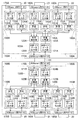
- FIG. 2 is an internal configuration diagram of the multiplex communication apparatuses 100A and 100B according to the present embodiment. As shown in FIG. 2, the multiplex communication apparatuses 100A and 100B according to the present embodiment are connected by the multiplex communication cable 101 such as the LAN line category 5e or an optical fiber as described above.
- the multiplex communication cable 101 such as the LAN line category 5e or an optical fiber as described above.
- the multiplex communication apparatus 100A includes a PHY-IC 110A for the multiplex side physical layer, a multiplex communication protocol processing unit 120A, input / output processing units 130A, 140A, 150A, a multiplex processing unit 160A, and a PHY- for the local side physical layer.
- the multiplex-side physical layer PHY-IC 110A is a 1000-base-t PHY-IC, and is an SFP optical transceiver when an optical fiber is used as the multiplex communication cable 101.
- the multiplex communication protocol processing unit 120A performs a synthesis / separation process on the multiplex communication protocols shown in FIGS.
- the multiplex communication protocol processing unit 120A includes a GMII-I / F data input unit 121A, a demultiplexing unit 122A, a multiplex mixing unit 123A, and a GMII-I / F data output unit 124A.
- the input / output processing units 130A, 140A, and 150A are Ethernet (registered trademark) signal input / output units to be multiplexed, and require a plurality of paths.
- the multiplex communication apparatus 100 ⁇ / b> A according to the present embodiment is installed in the A area 2. Therefore, the multiplex communication apparatus 100A according to the present embodiment includes three input / output processing units 130A, 130A, as shown in FIG. 2 as paths for the servo controller 12, the image processing apparatus 13, and the sequencer 14. 140A and 150A.
- Each input / output processing unit 130A, 140A, 150A includes MII-I / F data input units 131A, 141A, 151A, reception buffers 132A, 142A, 152A, MII-I / F data output units 133A, 143A, 153A, and transmission. There are buffers 134A, 144A, 154A.
- the MII-I / F data input units 131A, 141A, and 151A are physical layer and link layer I / Fs, and are MII-I / F data (25 MHz, 4 BIT) receiving units.
- the reception buffers 132A, 142A, and 152A are buffers that absorb a difference between 125 MHz, which is a clock for multiplex communication, and 25 MHz, which is an MII clock.
- the MII-I / F data output units 133A, 143A, and 153A are physical layer and link layer I / Fs, and are MII-I / F data (25 MHz, 4 BIT) transmission units.
- the transmission buffers 134A, 144A, 154A are data storage units for outputting data to the local side.
- the multiplex communication apparatus 100 ⁇ / b> A according to the present embodiment is installed in the A area 2. Therefore, in the multiplex communication apparatus 100A according to the present embodiment, the local side is the servo controller 12, the image processing apparatus 13, and the sequencer 14.
- the transmission buffers 134A, 144A, and 154A have a jitter (one block transmission / reception time, for example, 30 in the standard GbE of Ethernet (registered trademark) shown in FIGS.
- a jitter one block transmission / reception time, for example, 30 in the standard GbE of Ethernet (registered trademark) shown in FIGS.
- the transmission buffers 134A, 144A, and 154A determine that the frame delimiter is IPG (Inter-Packet Gap, MIN 12 bytes) when there is no data for a certain period of time, and cancel the continuous transmission state.
- IPG Inter-Packet Gap, MIN 12 bytes
- the multiplex processing unit 160A is a multiplex internal processing unit in an integrated circuit (specifically, FPGA or ASIC) having a multiplex communication protocol processing unit 120A and input / output processing units 130A, 140A, 150A.
- PHY-ICs 170A, 180A, and 190A for the local physical layer are PHY-ICs for 100base-tx, and are necessary for input / output of signals for a plurality of paths of Ethernet (registered trademark).
- the multiplex communication apparatus 100 ⁇ / b> A according to the present embodiment is installed in the A area 2.
- the multiplex communication apparatus 100A according to the present embodiment includes three local physical layer PHY-as shown in FIG. 2 as paths of the servo controller 12, the image processing apparatus 13, and the sequencer 14.
- the local physical layer PHY-IC 170A is connected to a LAN cable 20 for Ethernet (registered trademark) such as MECHATRLINK (registered trademark) -III.
- a LAN cable 21 for Ethernet (registered trademark) such as TCP / IP or UDP is connected to the local physical layer PHY-IC 180A.
- a LAN cable 22 for Ethernet (registered trademark) such as EtherCAT (registered trademark) is connected to the local physical layer PHY-IC 190A.
- the multiplex communication apparatus 100B includes the PHY-IC 110B for the multiplex side physical layer, the multiplex communication protocol processing unit 120B, the input / output processing units 130B, 140B, and 150B, the multiplex processing unit 160B, and the local side physical layer.
- Layer PHY-ICs 170B, 180B, and 190B are provided.
- the PHY-IC 110B for the multiplex side physical layer is a PHY-IC for 1000base-t, and is an SFP optical transceiver when an optical fiber is used as the multiplex communication cable 101.
- the multiplex communication protocol processing unit 120B performs a synthesis / separation process on the multiplex communication protocols shown in FIGS.
- the multiplex communication protocol processing unit 120B includes a GMII-I / F data input unit 121B, a demultiplexing unit 122B, a multiplex mixing unit 123B, and a GMII-I / F data output unit 124B.
- the input / output processing units 130B, 140B, and 150B are input / output units for Ethernet (registered trademark) signals to be multiplexed, and require a plurality of paths.
- the multiplex communication apparatus 100 ⁇ / b> B according to the present embodiment is installed in the B area 3. Therefore, the multiplex communication apparatus 100B according to the present embodiment includes three input / output signals as shown in FIG. 2 for the servo amplifier / motors 15 and 16, the camera 17, and the slaves 18 and 19, respectively.
- Each input / output processing unit 130B, 140B, 150B includes MII-I / F data input units 131B, 141B, 151B, reception buffers 132B, 142B, 152B, MII-I / F data output units 133B, 143B, 153B, and transmission. It has buffers 134B, 144B, 154B.
- the MII-I / F data input units 131B, 141B, and 151B are physical layer and link layer I / Fs, and are MII-I / F data (25 MHz, 4 BIT) receiving units.
- the reception buffers 132B, 142B, and 152B are buffers that absorb a difference between 125 MHz, which is a clock for multiplex communication, and 25 MHz, which is an MII clock.
- the MII-I / F data output units 133B, 143B, and 153B are physical layer and link layer I / Fs, and are MII-I / F data (25 MHz, 4 BIT) transmission units.
- the transmission buffers 134B, 144B, and 154B are data storage units for outputting data to the local side.
- the multiplex communication apparatus 100 ⁇ / b> B according to the present embodiment is installed in the B area 3. Therefore, in the multiplex communication apparatus 100B according to the present embodiment, the local side is the servo amplifiers / motors 15 and 16, the camera 17, and the slaves 18 and 19.
- the transmission buffers 134B, 144B, and 154B have a jitter (one block transmission / reception time, for example, 30 in the standard GbE of Ethernet (registered trademark) represented in FIGS.
- a jitter one block transmission / reception time, for example, 30 in the standard GbE of Ethernet (registered trademark) represented in FIGS.
- the transmission buffers 134B, 144B, and 154B determine that the frame delimiter is IPG (Inter-Packet Gap, MIN 12 bytes) when there is no data for a certain period of time, and cancel the continuous transmission state.
- IPG Inter-Packet Gap, MIN 12 bytes
- the data to be transmitted with the jitter of multiplex communication is not in the transmission buffers 134B, 144B, and 154B, and the continuity of the output data is lost, so the frame can be received correctly on the local side. It becomes abnormal.
- the multiplex processing unit 160B is a multiplex internal processing unit in an integrated circuit (specifically, FPGA or ASIC) having a multiplex communication protocol processing unit 120B and input / output processing units 130B, 140B, and 150B.
- PHY-ICs 170B, 180B, and 190B for the local physical layer are PHY-ICs for 100base-tx, and are necessary for input / output of signals for Ethernet (registered trademark) in multiple paths.
- the multiplex communication apparatus 100 ⁇ / b> B according to the present embodiment is installed in the B area 3.
- the multiplex communication apparatus 100B according to the present embodiment includes three local physical units as shown in FIG. 2 as the paths of the servo amplifiers / motors 15, 16, the camera 17, and the slaves 18, 19.
- a LAN cable 20 for Ethernet (registered trademark) such as MECHATRLINK (registered trademark) -III is connected to the local physical layer PHY-IC 170B.
- a LAN cable 21 for Ethernet (registered trademark) such as TCP / IP and UDP is connected to the local physical layer PHY-IC 180B.
- a LAN cable 22 for Ethernet (registered trademark) such as EtherCAT (registered trademark) is connected to the local physical layer PHY-IC 190B.
- the multiplex communication apparatuses 100A and 100B according to the present embodiment multiplex, for example, three lines of 100base-tx according to the Ethernet (registered trademark) standard GbE.
- LAN cable 20 for Ethernet such as MECHATROJSLINK (registered trademark) -III, Ethernet (registered trademark) such as TCP / IP, UDP, etc.
- LAN cable 21 and Ethernet (registered trademark) LAN cable 22 such as EtherCAT (registered trademark) are a single multiplexed communication cable 101, which is a single multiplexed communication line, and independent lines without analyzing the communication protocol. It is possible to multiplex without changing.
- the connected LAN cables 22 are multiplexed independently.
- FIG. 3 is a diagram showing a multiplex communication protocol of a half-duplex communication method for transmitting data from A area 2 to B area 3, but half-duplex for transmitting data from B area 3 to A area 2.
- the multiplex communication protocol of the communication method is not described.
- FIG. 4 shows a half-duplex communication protocol for transmitting data from B area 3 to A area 2, but transmits data from A area 2 to B area 3.
- the multiplex communication protocol of the half duplex communication system is not described.
- PHY-ICs 110A and 110B for the multi-side physical layer are PHY-ICs for 1000 base-t
- transmission / reception is performed with GMII (125 MHz * 8 BIT) which is the minimum unit of 1000 base-t.
- the 8 bits are represented by “B0”, “B1”, “B2”, “B3”, “B4”, “B5”, “B6”, “B7” arranged in the vertical axis in FIGS.
- the numerical values “0” to “14” arranged on the horizontal axis are the counter numbers of the clock (125 MHz, which is the same as that for the standard GbE) for performing multiplexed communication.
- the numerical values “15” to “29” arranged on the horizontal axis are the counter numbers of the clock (125 MHz, which is the same as that for the standard GbE) for performing multiplexed communication.
- the multiplex communication apparatuses 100A and 100B are the minimum unit of 100base-tx of 100base-tx according to the standard GbE of each local side Ethernet (registered trademark). Data transmission / reception is performed by adding a data presence / absence flag in units of 1 Nibble, 25 MHz, 4 BIT of an MII.
- MIIX-Y the data is represented by “MIIX-Y” where “X” is the line number and “Y” is the order in which the buffer is accumulated.
- the line number of “X” is any one of “1”, “2”, “3”, and the order of accumulation in the buffer of “Y” is “1”, “2”, “3”, “4”, It is either “5” or “6”.
- MIIX-Y present / not present is a flag indicating the presence / absence of data. “MIIX-Y present” indicates that “MIIX-Y” data is present. “No MIIX-Y” indicates that there is no data of “MIIX-Y”.
- each local side Ethernet (registered trademark) communication transmission and reception are performed in units of packets, and when there is no necessary data, there is no communication state. However, there is at least no communication between IPG (Inter-PacketPackGap, MIN 12 bytes) between packets.
- IPG Inter-PacketPackGap, MIN 12 bytes
- the PHY-ICs 110A and 110B for the multiplex side physical layer perform data transmission and reception at a fixed interval in order to multiplex with the minimum delay and jitter. For this reason, if there is no data to be transmitted to the local side and data that does not exist is transmitted to the local side, a communication error occurs. Therefore, as shown in FIG. 3 and FIG. 4, the data presence / absence flag information is added to each minimum unit of data, and MII 4-bit data is not output when there is no data.
- FIG. 5 shows multiplex communication when 1000 base-t 3 lines (CC-LinkIE (registered trademark), GigE_Vision (registered trademark), LAN line for PC)) are multiplexed with SFP (5 Gbps) in addition to 100 base-tx. It is a figure showing a protocol.
- an SFP (5 Gbps) optical transceiver is used instead of the PHY-IC 110B for the multi-side physical layer (see FIG. 2), which is the PHY-IC for 1000base-t.
- an optical fiber is used as the multiplex communication cable 101 (see FIG. 2).
- FIG. 5 is a diagram showing a multiplex communication protocol for transmitting data from the C factory to the D factory, and a diagram showing a multiplex communication protocol for transmitting data from the D factory to the C factory.
- GMII-I / F data (125 MHz, 8 BIT) is multiplexed as one unit at 1000 base-t.
- the 8 bits are represented by “B0” to “B7”, “B8” to “B15”, “B16” to “B23”, and “B24” to “B31” arranged on the vertical axis.
- the numerical values “0” to “9” arranged on the horizontal axis are the counter numbers of clocks for performing multiplexed communication.
- X is the number of three lines (CC-LinkIE (registered trademark), GigE_Vision (registered trademark), LAN line for PC)
- the line number of “X” is any one of “1” of CC-Link IE (registered trademark), “2” of GigE_Vision (registered trademark), and “3” of the LAN line for PC.
- “With / without GMIIX” is a flag indicating whether data exists. “With GMIIX” indicates that there is data of “GMIIX”. “No GMIIX” indicates that there is no data of “GMIIX”.
- “X” is the line number
- “Y” is the order of accumulation in the buffer, and the data is represented by “MIIX-Y”.
- the line number “X” includes “4” in addition to “1”, “2”, and “3” indicating the local sides.
- the order of accumulation in the “Y” buffer is either “1” or “2”.
- “MIIX-Y present / not present” is a flag indicating the presence / absence of data. “MIIX-Y present” indicates that “MIIX-Y” data is present. “No MIIX-Y” indicates that there is no data of “MIIX-Y”.
- a Hamming code FEC (15, 11) shortening system which is one of the forward error correction methods, is used to improve reliability. To do.
- This PORT is used for communication standards / uses that are difficult to retransmit.
- bit positions are fixed on the multiplexed data before and after multiplexing for a plurality of ports (see FIGS. 3, 4 and 5), and a plurality of industrial Ethernet (registered)
- the trademark path (reference numerals 1020, 1021, and 1022 in FIG. 6) can be wired by a single path (reference numeral 101 in FIG. 1).
- Ethernet (registered trademark) line is reduced between the A area 2 as the fixed part and the B area 3 as the movable part in the entire apparatus, or between different floors in the same factory. Is possible.
- the multiplex communication devices 100A and 100B according to the present embodiment are inserted into the configuration of FIG. 6 described in the “Background Art” column, and two multiplex communication devices 100A are inserted. , 100B, standard LAN lines corresponding to the same numbered ports are connected.
- multiplex communication devices 100A and 100B according to the present embodiment are GbE (1000base-t) multiplex communication devices
- 100base-tx is multiplexed up to 3 lines using the multiplex communication protocol shown in FIGS. Is possible.
- FIG. 3 since the internal data is independent, there is an abnormality (for example, a LAN cable loop, virus infection, etc.) in one of a plurality of lines. ) Does not affect other lines at all.
- an abnormality for example, a LAN cable loop, virus infection, etc.
- a one-way transfer is a delay of about 1.5 ⁇ s, and a jitter is about 240 ns (30 clocks for one transmission) (FIG. 3). (See FIG. 4).
- the delay is about 1.2 ⁇ s in one transfer in one direction, and the jitter is about 80 ns (at the time of one transmission with 10 clocks) (see FIG. 5). ).
- the physical layer of data in time for the communication speed can be used to multiplex any standard industrial Ethernet (registered trademark), making difficult settings for multiplexing, creating configuration files, and releasing There are no timing delays and it can be used immediately.
- this invention is not limited to the said embodiment, A various change is possible in the range which does not deviate from the meaning.
- the standards for industrial Ethernet (registered trademark) based on 100base include MECHATRLINK (registered trademark) -III, EtherCAT (registered trademark), EtherNet / IP (registered trademark), Profinet (registered trademark), and Modbus (registered trademark). Trademark), TCP / IP, or FL-net.
- TCP / IP or UDP communication there is TCP / IP or UDP communication to which a PC that performs normal data transmission / reception is connected.
- an SFP optical transceiver when an optical fiber is used as the multiplex communication cable 101, an SFP optical transceiver is used.
- an SFF optical transceiver may be used.
- Multiplex communication system 100A Multiplex communication device 100B Multiplex communication device 101 Multiplex communication cable 110A Multiplex side physical layer PHY-IC 110B PHY-IC for multiple physical layer 133A MII-I / F data output unit 134A Transmission buffer 133B MII-I / F data output unit 134B Transmission buffer 143A MII-I / F data output unit 144A Transmission buffer 143B MII-I / F data output unit 144B Transmission buffer 153A MII -I / F data output unit 154A Transmission buffer 153B MII-I / F data output unit 154B Transmission buffer 160A Multiplexing unit 160B Multiplexing unit
Landscapes
- Engineering & Computer Science (AREA)
- Computer Networks & Wireless Communication (AREA)
- Signal Processing (AREA)
- Time-Division Multiplex Systems (AREA)
- Small-Scale Networks (AREA)
Abstract
複数の産業用イーサネット(登録商標)を1本の経路で配線させることができる多重通信装置を提供すること。 多重通信システム1は、Aエリア2とBエリア3に分かれる。Aエリア2には、多重通信装置100Aが設置される。Bエリア3には、多重通信装置100Bが設置される。多重通信装置100A,100Bは、LAN線カテゴリー5e又は光ファイバ等の多重通信用ケーブル101で接続される。
Description
本発明は、産業用イーサネット(EtherCAT(登録商標)・MECHATROLINK(登録商標)-III等)を使用した装置の通信データを論理層と物理層の最小単位で送受信を行う多重通信装置に関するものである。
以下、従来技術の多重通信装置について説明する。
図6は、従来技術の通信システムのシステム構成図である。図6に表された多重通信システム1001は、Aエリア1002とBエリア1003に分かれる。
Aエリア1002には、システム制御装置1011、サーボコントローラ1012、画像処理装置1013、及びシーケンサ1014が設置される。
システム制御装置1011とサーボコントローラ1012は、MECHATROLINK(登録商標)-III等のイーサネット(登録商標)用のLANケーブル1020で接続される。
また、システム制御装置1011と画像処理装置1013は、TCP/IP,UDP等のイーサネット(登録商標)用のLANケーブル1021で接続される。
さらに、システム制御装置1011とシーケンサ1014は、EtherCAT(登録商標)等のイーサネット(登録商標)用のLANケーブル1022で接続される。
システム制御装置1011は、装置全体を制御する。装置全体は、図6に表されたように、固定部としてのAエリア1002と、可動部としてのBエリア1003である。尚、装置全体に代えて、C工場としてのAエリア1002と、D工場としてのBエリア1003としてもよい。画像処理装置1013は、監視等に使用される。尚、画像処理装置1013は、画像表示装置に代えてもよい。
Bエリア1003には、サーボアンプ/モータ1015,1016、カメラ1017、及びスレーブ1018,1019が設置される。スレーブ1018,1019は、ここでは、リレー又はセンサーである。
サーボアンプ/モータ1015,1016は、MECHATROLINK(登録商標)-III等のイーサネット(登録商標)用のLANケーブル1020で接続される。さらに、サーボアンプ/モータ1015,1016は、Aエリア1002のサーボコントローラ1012に、MECHATROLINK(登録商標)-III等のイーサネット(登録商標)用のLANケーブル1020で接続される。
カメラ1017は、Aエリア1002の画像処理装置1013に、TCP/IP,UDP等のイーサネット(登録商標)用のLANケーブル1021で接続される。
スレーブ1018,1019は、EtherCAT(登録商標)等のイーサネット(登録商標)用のLANケーブル1022で接続される。さらに、スレーブ1018,1019は、Aエリア1002のシーケンサ1014に、EtherCAT(登録商標)等のイーサネット(登録商標)用のLANケーブル1022で接続される。
尚、従来技術の多重通信装置に関連する発明としては、以下の各特許文献に記載された発明がある。
しかしながら、図6に表された多重通信システム1001では、複数の経路毎にLANケーブル1020,1021,1022を用意して敷設する。
つまり、ワイヤーハーネス(LANケーブル1020,1021,1022)の本数が多く、装置内の可動部としてのBエリア1003に使用した場合には、ワイヤーハーネス(LANケーブル1020,1021,1022)の全体が太くなり、曲げの屈曲半径Rを十分に確保したケーブルダクトが必要となり、小型化に影響する。
C工場としてのAエリア1002と、D工場としてのBエリア1003とした場合には、ワイヤーハーネス(LANケーブル1020,1021,1022)の本数に加えて、ワイヤーハーネス(LANケーブル1020,1021,1022)の距離が長いため、LANケーブル1020,1021,1022の重量が重い、コストが高い、敷設する電線が太いこと等が要因となって、工事費がかさむ。
また、図6に表された多重通信システム1001では、固定部としてのAエリア1002と可動部としてのBエリア1003との間を1本のLAN線で接続する場合には、先ず、使用する特定の規格1と規格2のGateway装置を購入し、どれか1つの回線に統一した後で、1本のLAN線で接続する。
使用する規格のGateway装置が存在しない場合や、産業用イーサネット(登録商標)が新しい規格である場合には、Gateway装置の開発リードタイム分、工事の進捗が遅れたりする。
使用する規格の組合せが複数で大量生産されない組合せもあり、そのような場合には、工事費がかさむ。
Gateway装置を使用する場合には、変換前のフレームを解析した後に変換後のフレームを作成するため、遅延が大きくなり、リアルタイム性の必要な部分に使用することができず、比較的遅い周期のものになる。
スレーブ1018,1019の規格が違う場合には、Gateway後は、市販メーカーのサポート外の規格(例えば、Profinet(登録商標)用で市販されたスレーブをEtherCAT(登録商標)で使用)となるため、スレーブ設定ファイルが準備されていない。そのため、設定ファイル(先程の例では、EtherCAT(登録商標)用設定ファイル)を新規に作成するので、(規格を理解し、その後、設定ファイルを記述し、動作確認を行う等の)手間と時間がかかる。
また、それぞれの規格には一長一短があったり、欲しいコンポーネントのI/F(インターフェイス)に限られた製品しかなく選択枝が無かったり、過去に納入した装置の規格があったりと、同じ装置内・同じ工場内でも、一つの規格に統一されないケースがある。
特に、産業用イーサネット(登録商標)の規格の中には、PC等でよく利用されているハブが使用できない規格があり、また、専用の中継器でも他の規格を接続して使用できないケースがある。
そこで、本発明は、上述した点を鑑みてなされたものであり、複数の産業用イーサネット(登録商標)を1本の経路で配線させることができる多重通信装置を提供することを課題とする。
この課題を解決するためになされた請求項1に係る発明は、複数のポートの産業用イーサネット(登録商標)の信号を1つの伝送路にのせる多重通信装置であって、データの論理層と物理層の内部インターフェースであるメディアインペンデントインターフェース最小単位データにデータ有無のフラグ情報をつけて、データの最小単位の送受信を行い、データの連続性を確保した状態で多重化すること、を特徴とする。
尚、「複数のポートの産業用イーサネット(登録商標)の信号」とは、例えば、100base-txがある。
「データの論理層と物理層の内部インターフェース」とは、例えば、MII:Media Independent Intergace,GMII:Gigabit Media Independent Intergace等がある。
「最小単位」とは、例えば、MIIでは、1Nibbleの25MHz,4BITであり、GMIIでは、125MHz,8BITである。
「データの最小単位の送受信を行い」とは、例えば、イーサネット(登録商標)の規格GbEによる100base-txの半2重通信時では一定の固定間隔(15クロック)で送受信を切り替え、後述するSFP等を使用する全2重通信では一定の固定間隔(10クロック)で送受信を行う。
本発明では、複数のポートが多重化前と多重化後、多重化データ上でもビット位置が固定しており、複数の産業用イーサネット(登録商標)を1本の経路で配線させることができる。よって、省配線化ができる。
[1.多重通信システムのシステム構成]
以下、本発明を具体化した多重通信装置について図面を参照しつつ説明する。図1は、本発明の一実施形態に係る多重通信装置が使用された多重通信システムのシステム構成図である。
以下、本発明を具体化した多重通信装置について図面を参照しつつ説明する。図1は、本発明の一実施形態に係る多重通信装置が使用された多重通信システムのシステム構成図である。
図1に表された多重通信システム1は、Aエリア2とBエリア3に分かれる。Aエリア2には、本実施形態に係る多重通信装置100Aが設置される。Bエリア3には、本実施形態に係る多重通信装置100Bが設置される。
Aエリア2には、本実施形態に係る多重通信装置100Aの他に、システム制御装置11、サーボコントローラ12、画像処理装置13、及びシーケンサ14が設置される。
システム制御装置11と本実施形態に係る多重通信装置100Aは、サーボコントローラ12を介して、MECHATROLINK(登録商標)-III等のイーサネット(登録商標)用のLANケーブル20で接続される。
また、システム制御装置11と本実施形態に係る多重通信装置100Aは、画像処理装置13を介して、TCP/IP,UDP等のイーサネット(登録商標)用のLANケーブル21で接続される。
さらに、システム制御装置11と本実施形態に係る多重通信装置100Aは、シーケンサ14を介して、EtherCAT(登録商標)等のイーサネット(登録商標)用のLANケーブル22で接続される。
システム制御装置11は、装置全体を制御する。装置全体は、図1に表されたように、固定部としてのAエリア2と、可動部としてのBエリア3である。尚、装置全体に代えて、C工場としてのAエリア2と、D工場としてのBエリア3としてもよい。画像処理装置13は、監視等に使用される。尚、画像処理装置13は、画像表示装置に代えてもよい。
Bエリア3には、本実施形態に係る多重通信装置100Bの他に、サーボアンプ/モータ15,16、カメラ17、及びスレーブ18,19が設置される。スレーブ18,19は、本実施形態では、リレー又はセンサーである。
サーボアンプ/モータ15,16は、Aエリア2のサーボコントローラ12とデータ通信を行う。カメラ17は、Aエリア2の画像処理装置13(又は画像表示装置)とデータ通信を行う。スレーブ18,19は、Aエリア2のシーケンサ14とデータ通信を行う。
本実施形態に係る多重通信装置100Bとサーボアンプ/モータ15,16は、MECHATROLINK(登録商標)-III等のイーサネット(登録商標)用のLANケーブル20で接続される。
本実施形態に係る多重通信装置100Bとカメラ17は、TCP/IP,UDP等のイーサネット(登録商標)用のLANケーブル21で接続される。
本実施形態に係る多重通信装置100Bとスレーブ18,19は、EtherCAT(登録商標)等のイーサネット(登録商標)用のLANケーブル22で接続される。
そして、本実施形態に係る多重通信装置100A,100Bは、LAN線カテゴリー5e又は光ファイバ等の多重通信用ケーブル101で接続される。
[2.システム制御装置の内部構成]
図2は、本実施形態に係る多重通信装置100A,100Bの内部構成図である。図2に表されたように、本実施形態に係る多重通信装置100A,100Bは、上述したように、LAN線カテゴリー5e又は光ファイバ等の多重通信用ケーブル101で接続される。
図2は、本実施形態に係る多重通信装置100A,100Bの内部構成図である。図2に表されたように、本実施形態に係る多重通信装置100A,100Bは、上述したように、LAN線カテゴリー5e又は光ファイバ等の多重通信用ケーブル101で接続される。
本実施形態に係る多重通信装置100Aは、多重側物理層用PHY-IC110A、多重通信プロトコル処理部120A、入出力処理部130A,140A,150A、多重処理部160A、及びローカル側物理層用PHY-IC170A,180A,190Aを有する。
多重側物理層用PHY-IC110Aは、1000base-t用PHY-ICであり、多重通信用ケーブル101として光ファイバが使用される時はSFPの光トランシーバである。
多重通信プロトコル処理部120Aは、後述する図3乃至図5等の多重通信プロトコルを合成・分離処理を行う。多重通信プロトコル処理部120Aは、GMII-I/Fデータ入力部121A、多重分離部122A、多重混合部123A、及びGMII-I/Fデータ出力部124Aを有する。
入出力処理部130A,140A,150Aは、多重化対象となるイーサネット(登録商標)用信号の入出力部であり、複数経路分を必要とする。具体的には、図1に表された多重通信システム1では、本実施形態に係る多重通信装置100AはAエリア2に設置される。従って、本実施形態に係る多重通信装置100Aには、サーボコントローラ12、画像処理装置13、及びシーケンサ14の各経路分として、図2に表されたように、3個の入出力処理部130A,140A,150Aがある。
各入出力処理部130A,140A,150Aは、MII-I/Fデータ入力部131A,141A,151A、受信バッファ132A,142A,152A、MII-I/Fデータ出力部133A,143A,153A、及び送信バッファ134A,144A,154Aを有する。
MII-I/Fデータ入力部131A,141A,151Aは、物理層とリンク層のI/Fであり、MII-I/Fデータ(25MHz、4BIT)の受信部である。
受信バッファ132A,142A,152Aは、多重通信のクロックである125MHzとMIIのクロックである25MHzの差を吸収するバッファである。
MII-I/Fデータ出力部133A,143A,153Aは、物理層とリンク層のI/Fであり、MII-I/Fデータ(25MHz、4BIT)の送信部である。
送信バッファ134A,144A,154Aは、ローカル側にデータを出力するためのデータ蓄積部である。具体的には、図1に表された多重通信システム1では、本実施形態に係る多重通信装置100AはAエリア2に設置される。従って、本実施形態に係る多重通信装置100Aにおいて、当該ローカル側とは、サーボコントローラ12、画像処理装置13、及びシーケンサ14である。
図2に戻り、送信バッファ134A,144A,154Aは、多重通信プロトコル上のジッタ(1ブロックの送受信時間分、例えば、後述する図3,4で表されたイーサネット(登録商標)の規格GbEでは30回)を予め考慮し、作成された閾値個数分の4BITデータが蓄積されたら、連続送信を開始する。また、送信バッファ134A,144A,154Aは、ある時間以上データが無いときに、フレームの区切りのIPG(Inter-Packet Gap、MIN12バイト)と判断し、連続送信の状態を解除する。
尚、バッファ1個以上で送信を開始すると、多重通信のジッタ分で送信するデータが送信バッファ134A,144A,154Aになく、出力データの連続性がなくなるので、上記ローカル側でフレームを正しく受信できず、異常となる。
多重処理部160Aは、多重通信プロトコル処理部120A、及び入出力処理部130A,140A,150Aを有した集積回路(具体的には、FPGA又はASIC)での多重化内部処理部である。
ローカル側物理層用PHY-IC170A,180A,190Aは、100base-tx用PHY-ICであり、複数路のイーサネット(登録商標)用信号の入出力に必要となる。具体的には、図1に表された多重通信システム1では、本実施形態に係る多重通信装置100AはAエリア2に設置される。従って、本実施形態に係る多重通信装置100Aには、サーボコントローラ12、画像処理装置13、及びシーケンサ14の各路として、図2に表されたように、3個のローカル側物理層用PHY-IC170A,180A,190Aがある。
ローカル側物理層用PHY-IC170Aには、MECHATROLINK(登録商標)-III等のイーサネット(登録商標)用のLANケーブル20が接続される。ローカル側物理層用PHY-IC180Aには、TCP/IP,UDP等のイーサネット(登録商標)用のLANケーブル21が接続される。ローカル側物理層用PHY-IC190Aには、EtherCAT(登録商標)等のイーサネット(登録商標)用のLANケーブル22が接続される。
同様にして、本実施形態に係る多重通信装置100Bは、多重側物理層用PHY-IC110B、多重通信プロトコル処理部120B、入出力処理部130B,140B,150B、多重処理部160B、及びローカル側物理層用PHY-IC170B,180B,190Bを有する。
多重側物理層用PHY-IC110Bは、1000base-t用PHY-ICであり、多重通信用ケーブル101として光ファイバが使用される時はSFPの光トランシーバである。
多重通信プロトコル処理部120Bは、後述する図3乃至図5等の多重通信プロトコルを合成・分離処理を行う。多重通信プロトコル処理部120Bは、GMII-I/Fデータ入力部121B、多重分離部122B、多重混合部123B、及びGMII-I/Fデータ出力部124Bを有する。
入出力処理部130B,140B,150Bは、多重化対象となるイーサネット(登録商標)用信号の入出力部であり、複数経路分を必要とする。具体的には、図1に表された多重通信システム1では、本実施形態に係る多重通信装置100BはBエリア3に設置される。従って、本実施形態に係る多重通信装置100Bには、サーボアンプ/モータ15,16、カメラ17、及びスレーブ18,19の各経路分として、図2に表されたように、3個の入出力処理部130B,140B,150Bがある。
各入出力処理部130B,140B,150Bは、MII-I/Fデータ入力部131B,141B,151B、受信バッファ132B,142B,152B、MII-I/Fデータ出力部133B,143B,153B、及び送信バッファ134B,144B,154Bを有する。
MII-I/Fデータ入力部131B,141B,151Bは、物理層とリンク層のI/Fであり、MII-I/Fデータ(25MHz、4BIT)の受信部である。
受信バッファ132B,142B,152Bは、多重通信のクロックである125MHzとMIIのクロックである25MHzの差を吸収するバッファである。
MII-I/Fデータ出力部133B,143B,153Bは、物理層とリンク層のI/Fであり、MII-I/Fデータ(25MHz、4BIT)の送信部である。
送信バッファ134B,144B,154Bは、ローカル側にデータを出力するためのデータ蓄積部である。具体的には、図1に表された多重通信システム1では、本実施形態に係る多重通信装置100BはBエリア3に設置される。従って、本実施形態に係る多重通信装置100Bにおいて、当該ローカル側とは、サーボアンプ/モータ15,16、カメラ17、及びスレーブ18,19である。
図2に戻り、送信バッファ134B,144B,154Bは、多重通信プロトコル上のジッタ(1ブロックの送受信時間分、例えば、後述する図3,4で表されたイーサネット(登録商標)の規格GbEでは30回)を予め考慮し、作成された閾値個数分の4BITデータが蓄積されたら、連続送信を開始する。また、送信バッファ134B,144B,154Bは、ある時間以上データが無いときに、フレームの区切りのIPG(Inter-Packet Gap、MIN12バイト)と判断し、連続送信の状態を解除する。
尚、バッファ1個以上で送信を開始すると、多重通信のジッタ分で送信するデータが送信バッファ134B,144B,154Bになく、出力データの連続性がなくなるので、上記ローカル側でフレームを正しく受信できず、異常となる。
多重処理部160Bは、多重通信プロトコル処理部120B、及び入出力処理部130B,140B,150Bを有した集積回路(具体的には、FPGA又はASIC)での多重化内部処理部である。
ローカル側物理層用PHY-IC170B,180B,190Bは、100base-tx用PHY-ICであり、複数路のイーサネット(登録商標)用信号の入出力に必要となる。具体的には、図1に表された多重通信システム1では、本実施形態に係る多重通信装置100BはBエリア3に設置される。従って、本実施形態に係る多重通信装置100Bには、サーボアンプ/モータ15,16、カメラ17、及びスレーブ18,19の各路として、図2に表されたように、3個のローカル側物理層用PHY-IC170B,180B,190Bがある。
ローカル側物理層用PHY-IC170Bには、MECHATROLINK(登録商標)-III等のイーサネット(登録商標)用のLANケーブル20が接続される。ローカル側物理層用PHY-IC180Bには、TCP/IP,UDP等のイーサネット(登録商標)用のLANケーブル21が接続される。ローカル側物理層用PHY-IC190Bには、EtherCAT(登録商標)等のイーサネット(登録商標)用のLANケーブル22が接続される。
上記の構成により、本実施形態に係る多重通信装置100A,100Bは、例えば、イーサネット(登録商標)の規格GbEによる100base-txの3回線を多重化するものである。
従来では、1系統にまとめることができない規格違いの3回線(MECHATROJSLINK(登録商標)-III等のイーサネット(登録商標)用のLANケーブル20、TCP/IP,UDP等のイーサネット(登録商標)用のLANケーブル21、及びEtherCAT(登録商標)等のイーサネット(登録商標)用のLANケーブル22)を、1本の多重化通信線である多重通信用ケーブル101で、通信プロトコルの解析なく、独立した回線のままで、多重化することが可能である。
つまり、ローカル側物理層用PHY-IC170A,170Bに接続されたLANケーブル20、ローカル側物理層用PHY-IC180A,180Bに接続されたLANケーブル21、及びローカル側物理層用PHY-IC190A,190Bに接続されたLANケーブル22は、独立して多重化される。
[3.イーサネット(登録商標)の規格GbEによる多重通信プロトコル]
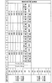
多重側物理層用PHY-IC110A,110Bが1000base-t用PHY-ICである場合には、本実施形態に係る多重通信装置100A,100Bは半2重通信方式で送受信を行う。図3,図4は、本実施形態に係る多重通信装置100A,100B(図2参照)が半2重通信方式で送受信を行う際のイーサネット(登録商標)の規格GbEによる多重通信プロトコルが表わされた図である。
多重側物理層用PHY-IC110A,110Bが1000base-t用PHY-ICである場合には、本実施形態に係る多重通信装置100A,100Bは半2重通信方式で送受信を行う。図3,図4は、本実施形態に係る多重通信装置100A,100B(図2参照)が半2重通信方式で送受信を行う際のイーサネット(登録商標)の規格GbEによる多重通信プロトコルが表わされた図である。
図3,図4では、縦軸に通信方向が表される。図3は、Aエリア2からBエリア3にデータを送信する半2重通信方式の多重通信プロトコルが表わされた図であるが、Bエリア3からAエリア2にデータを送信する半2重通信方式の多重通信プロトコルは記載されていない。これに対して、図4は、Bエリア3からAエリア2にデータを送信する半2重通信方式の多重通信プロトコルが表された図であるが、Aエリア2からBエリア3にデータを送信する半2重通信方式の多重通信プロトコルは記載されていない。
多重側物理層用PHY-IC110A,110B(図2参照)が1000base-t用PHY-ICである場合には、1000base-tの最小単位であるGMII(125MHz*8BIT)で送受信が行われる。その8BITは、図3,図4では、縦軸に並んだ「B0」,「B1」,「B2」,「B3」,「B4」,「B5」,「B6」,「B7」で表される。
図3では、横軸に並んだ「0」~「14」の数値は、多重化通信を行うクロック(規格GbE用と同じ125MHz)のカウンタ数である。同様にして、図4では、横軸に並んだ「15」~「29」の数値は、多重化通信を行うクロック(規格GbE用と同じ125MHz)のカウンタ数である。
図3,図4では、本実施形態に係る多重通信装置100A,100B(図2参照)は、上記各ローカル側のイーサネット(登録商標)の規格GbEによる100base-txの100base-txの最小単位であるMIIの1Nibble,25MHz,4BITを単位として、データ有無フラグを追加して、データの送受信を行う。
図3,図4では、「X」を回線番号、「Y」をバッファにたまった順番とすると、データが「MIIX-Y」で表わされる。「X」の回線番号は「1」,「2」,「3」のいずれかであり、「Y」のバッファにたまった順番は「1」,「2」,「3」,「4」,「5」,「6」のいずれかである。「MIIX-Y有/無」は、データ有無のフラグである。「MIIX-Y有」は、「MIIX-Y」のデータが有ることを表す。「MIIX-Y無」は、「MIIX-Y」のデータが無いことを表す。
尚、「空き」は、データそのものが存在しないことを表す。
図3に表されたように、カウンタ数が「0」,「1」の通信開始時は多重側物理層用PHY-IC110A,110B(図2参照)により決まったプリアンブル2個が送受信される。カウンタ数が「14」では、送受信を切り替えるため、お互いに送信OFFの状態とする。
図4に表されたように、カウンタ数が「15」~「29」の後半15回分は、送受信の方向を切り替えて通信を行う。
一般的に、上記各ローカル側のイーサネット(登録商標)の通信では、パケット単位で送受信が行われ、必要なデータがない時に無通信状態となる。但し、パケット間は、最低でも、IPG(Inter-Packet Gap、MIN12バイト)間分の無通信が有る。
一方、多重側物理層用PHY-IC110A,110B(図2参照)は、最小の遅延・ジッタで多重化するために、一定の固定間隔でデータ送受信を行う。そのため、上記ローカル側に送信すべきデータがないときに、存在しないデータを上記ローカル側に送信すると、通信異常となる。従って、図3,図4に表したように、最小単位のデータ毎にデータ有無のフラグの情報を付加し、データが無いときはMIIの4BITデータを出力しない。
[4.SFP(5Gbps)による多重通信プロトコル]
図5は、100base-txの他に、1000base-tの3回線(CC-LinkIE(登録商標)、GigE_Vision(登録商標)、PC用LAN回線)をSFP(5Gbps)で多重化したときの多重通信プロトコルが表わされた図である。この場合には、上述したように、1000base-t用PHY-ICである多重側物理層用PHY-IC110B(図2参照)に代えて、SFP(5Gbps)の光トランシーバが使用される。さらに、多重通信用ケーブル101(図2参照)として光ファイバが使用される。
図5は、100base-txの他に、1000base-tの3回線(CC-LinkIE(登録商標)、GigE_Vision(登録商標)、PC用LAN回線)をSFP(5Gbps)で多重化したときの多重通信プロトコルが表わされた図である。この場合には、上述したように、1000base-t用PHY-ICである多重側物理層用PHY-IC110B(図2参照)に代えて、SFP(5Gbps)の光トランシーバが使用される。さらに、多重通信用ケーブル101(図2参照)として光ファイバが使用される。
図5では、縦軸に通信方向が表される。図5は、C工場からD工場にデータを送信する多重通信プロトコルが表わされた図であるとともに、D工場からC工場にデータを送信する多重通信プロトコルが表された図である。
100base-txのときのMII-I/Fデータ(25MHz,4BIT)に対して、1000base-tでは、GMII-I/Fデータ(125MHz,8BIT)を1つの単位として多重化する。その8BITは、図5では、縦軸に並んだ「B0」~「B7」,「B8」~「B15」,「B16」~「B23」,「B24」~「B31」で表される。
さらに、図5では、横軸に並んだ「0」~「9」の数値は、多重化通信を行うクロックのカウンタ数である。
図5では、「X」を、3回線(CC-LinkIE(登録商標)、GigE_Vision(登録商標)、PC用LAN回線)の番号とすると、データが「GMIIX」で表わされる。「X」の回線番号は、CC-LinkIE(登録商標)の「1」,GigE_Vision(登録商標)の「2」,PC用LAN回線の「3」のいずれかである。「GMIIX有/無」は、データ有無のフラグである。「GMIIX有」は、「GMIIX」のデータが有ることを表す。「GMIIX無」は、「GMIIX」のデータが無いことを表す。
また、図5では、「X」を回線番号、「Y」をバッファにたまった順番とすると、データが「MIIX-Y」で表わされる。「X」の回線番号には、上記各ローカル側を意味する「1」,「2」,「3」に加え、「4」がある。また、「Y」のバッファにたまった順番は「1」,「2」のいずれかである。「MIIX-Y有/無」は、データ有無のフラグである。「MIIX-Y有」は、「MIIX-Y」のデータが有ることを表す。「MIIX-Y無」は、「MIIX-Y」のデータが無いことを表す。
特に、図5では、「MII4-1」と「MII4-2」には、信頼性を高めるために、前方誤り訂正方式の1つであるハミング符号のFEC(15,11)の短縮系を使用する。再送をきらう通信規格・用途には、このPORTを使用する。
図5に表されたSFP(5Gbps)の場合には、図3,図4に表されたGbEの場合とは違い、全2重通信方式であり、プリアンブルがなく、転送速度が速い特徴を持つ。また、多重通信用ケーブル101(図2参照)として光ファイバが使用されるため、長距離間(数km)を多重化できる。
[5.まとめ]
すなわち、本実施形態では、複数のポートが多重化前と多重化後、多重化データ上でもビット位置が固定しており(図3,図4,図5参照)、複数の産業用イーサネット(登録商標)の経路(図6の符号1020,1021,1022)を1本の経路(図1の符号101)で配線させることができる。
すなわち、本実施形態では、複数のポートが多重化前と多重化後、多重化データ上でもビット位置が固定しており(図3,図4,図5参照)、複数の産業用イーサネット(登録商標)の経路(図6の符号1020,1021,1022)を1本の経路(図1の符号101)で配線させることができる。
よって、省配線化ができる。本実施形態では、装置全体における固定部としてのAエリア2と可動部としてのBエリア3との間で、あるいは、同じ工場における異なる階数との間で、イーサネット(登録商標)の回線の省配線化が可能である。
C工場とD工場の間のような長距離の場合は、ケーブル代の他に、敷設に必要な部品代や工事代が安価で済む。
本実施形態では、「背景技術」の欄で説明した図6の構成に対し、図2に表したように、本実施形態に係る多重通信装置100A,100Bを挿入し、2つの多重通信装置100A,100B間で、同じ番号のポートに対応する規格のLAN線を接続する。
本実施形態に係る多重通信装置100A,100BがGbE(1000base-t)による多重通信装置の場合は、図3,図4に表された多重通信プロトコルで、100base-txを最大3回線を多重化することが可能である。
本実施形態では、図3,図4,図5に表されたように、内部データ上は独立しているので、複数の回線内の1つに異常(例えば、LANケーブルのループ、ウイルス感染等)が発生しても、他の回線に全く影響を及ぼさない。
従って、例えば、外部接続しているPC用LAN回線がウイルス感染しても、装置制御を行う別回線には全く影響せず、安定した生産ができる。
本実施形態では、図3,図4,図5に表されたように、最小単位のデータを基に多重化通信プロトコルにしているので、産業用イーサネット(登録商標)で問題となる遅延時間・ジッタが小さく、ほとんど影響しない。
具体的には、GbEによる多重通信装置では、片方向1回の転送で、約1.5μs程度の遅延であり、ジッタは約240ns(30クロックで1回分の送信時)である(図3,図4参照)。これに対して、SFPによる多重通信装置では、片方向1回の転送で、約1.2μs程度の遅延であり、ジッタは約80ns(10クロックで1回分の送信時)である(図5参照)。
本実施形態のように、パケット解析なしに多重化しているために、通信速度的に間に合うデータの物理層(多重側物理層用PHY-IC110A,110B、ローカル側物理層用PHY-IC170A,180A,190A、及びローカル側物理層用PHY-IC170B,180B,190B)を用意すれば、どんな規格の産業用イーサネット(登録商標)でも多重化でき、多重化のための難しい設定、設定ファイルの作成、リリースタイミングの遅れ等がなく、すぐに使用することができる。
従来のように、パケット単位でCRCチェック等を行ってからデータ通信すると、フレームのデータ量分の遅延が追加されて、フィードバック制御を行っているような産業用イーサネット(登録商標)では、遅延が大きく、正常に動作しないケースもある。また、データに識別子があると、識別子がデータ化けした場合、少なくとも2つの回線に影響がある。しかしながら、本実施形態では、図3,図4,図5に表されたように、固定ビットに割り付けているので、多重処理部160A,160Bでデータ化けが発生しても、複数のポートの対応を誤認することがない。
[6.その他]
尚、本発明は上記実施形態に限定されるものでなく、その趣旨を逸脱しない範囲で様々な変更が可能である。
例えば、100baseをベースとした産業用イーサネット(登録商標)の規格としては、MECHATROLINK(登録商標)-III、EtherCAT(登録商標)、EtherNet/IP(登録商標)、Profinet(登録商標)、Modbus(登録商標)、TCP/IP、又はFL-net等がある。
尚、本発明は上記実施形態に限定されるものでなく、その趣旨を逸脱しない範囲で様々な変更が可能である。
例えば、100baseをベースとした産業用イーサネット(登録商標)の規格としては、MECHATROLINK(登録商標)-III、EtherCAT(登録商標)、EtherNet/IP(登録商標)、Profinet(登録商標)、Modbus(登録商標)、TCP/IP、又はFL-net等がある。
1000baseをベースとした産業用イーサネット(登録商標)の規格としては、CC-LinkIE(登録商標)等がある。
また、その他にも、通常の情報系のデータ送受信を行うPCが接続されたTCP/IP又はUDPの通信も存在する。
本実施形態では、多重通信用ケーブル101として光ファイバが使用される時はSFPの光トランシーバであったが、SFFの光トランシーバであってもよい。
1 多重通信システム
100A 多重通信装置
100B 多重通信装置
101 多重通信用ケーブル
110A 多重側物理層用PHY-IC
110B 多重側物理層用PHY-IC
133A MII-I/Fデータ出力部
134A 送信バッファ
133B MII-I/Fデータ出力部
134B 送信バッファ
143A MII-I/Fデータ出力部
144A 送信バッファ
143B MII-I/Fデータ出力部
144B 送信バッファ
153A MII-I/Fデータ出力部
154A 送信バッファ
153B MII-I/Fデータ出力部
154B 送信バッファ
160A 多重処理部
160B 多重処理部
100A 多重通信装置
100B 多重通信装置
101 多重通信用ケーブル
110A 多重側物理層用PHY-IC
110B 多重側物理層用PHY-IC
133A MII-I/Fデータ出力部
134A 送信バッファ
133B MII-I/Fデータ出力部
134B 送信バッファ
143A MII-I/Fデータ出力部
144A 送信バッファ
143B MII-I/Fデータ出力部
144B 送信バッファ
153A MII-I/Fデータ出力部
154A 送信バッファ
153B MII-I/Fデータ出力部
154B 送信バッファ
160A 多重処理部
160B 多重処理部
Claims (6)
- 複数のポートの産業用イーサネット(登録商標)の信号を1つの伝送路にのせる多重通信装置であって、
データの論理層と物理層の内部インターフェースであるメディアインペンデントインターフェース最小単位データにデータ有無のフラグ情報をつけて、データの最小単位の送受信を行い、データの連続性を確保した状態で多重化すること、を特徴とする多重通信装置。 - 前記物理層として用いられる光トランシーバと、
多重通信用ワイヤーハーネスとして用いられる光ファイバと、を備えたこと、を特徴とする請求項1に記載の多重通信装置。 - 前記物理層として用いられるイーサネット(登録商標)用の物理層回路と、
多重通信用ワイヤーハーネスとして用いられるLAN線と、を備えたこと、を特徴とする請求項1に記載の多重通信装置。 - ローカル出力部と、
バッファと、を備え、
前記ローカル出力部は、連続的に出力するためのデータ数分を前記バッファにためた後に、前記バッファにためたデータの出力を開始すること、を特徴とする請求項1に記載の多重通信装置。 - 前記複数のポートを、多重化の通信プロトコル上で、固定ビットに割り当てること、を特徴とする請求項1に記載の多重通信装置。
- 前記多重化の処理を行うデバイスとしてFPGAを備えること、を特徴とする請求項1に記載の多重通信装置。
Priority Applications (2)
| Application Number | Priority Date | Filing Date | Title |
|---|---|---|---|
| PCT/JP2014/073797 WO2016038684A1 (ja) | 2014-09-09 | 2014-09-09 | 多重通信装置 |
| JP2016547291A JP6438964B2 (ja) | 2014-09-09 | 2014-09-09 | 多重通信装置 |
Applications Claiming Priority (1)
| Application Number | Priority Date | Filing Date | Title |
|---|---|---|---|
| PCT/JP2014/073797 WO2016038684A1 (ja) | 2014-09-09 | 2014-09-09 | 多重通信装置 |
Publications (1)
| Publication Number | Publication Date |
|---|---|
| WO2016038684A1 true WO2016038684A1 (ja) | 2016-03-17 |
Family
ID=55458477
Family Applications (1)
| Application Number | Title | Priority Date | Filing Date |
|---|---|---|---|
| PCT/JP2014/073797 Ceased WO2016038684A1 (ja) | 2014-09-09 | 2014-09-09 | 多重通信装置 |
Country Status (2)
| Country | Link |
|---|---|
| JP (1) | JP6438964B2 (ja) |
| WO (1) | WO2016038684A1 (ja) |
Cited By (2)
| Publication number | Priority date | Publication date | Assignee | Title |
|---|---|---|---|---|
| JP2017184086A (ja) * | 2016-03-31 | 2017-10-05 | 富士機械製造株式会社 | 多重化通信システム及び作業機 |
| WO2017179156A1 (ja) * | 2016-04-13 | 2017-10-19 | 富士機械製造株式会社 | 対基板作業機 |
Citations (4)
| Publication number | Priority date | Publication date | Assignee | Title |
|---|---|---|---|---|
| JPS63169150A (ja) * | 1987-01-06 | 1988-07-13 | Fujitsu Ltd | デ−タ送信回路 |
| JP2006067581A (ja) * | 2004-08-24 | 2006-03-09 | Samsung Electronics Co Ltd | データ多重化方法、フィールドプログラマブルゲートアレイ、及び光ネットワーク |
| JP2007110457A (ja) * | 2005-10-14 | 2007-04-26 | Hitachi Communication Technologies Ltd | 伝送装置 |
| JP2012114883A (ja) * | 2010-11-29 | 2012-06-14 | Furukawa Electric Co Ltd:The | 配電系監視制御装置及び電力配電システム用監視制御システム |
Family Cites Families (3)
| Publication number | Priority date | Publication date | Assignee | Title |
|---|---|---|---|---|
| JPH06247537A (ja) * | 1993-02-25 | 1994-09-06 | Tsubakimoto Chain Co | 仕分け装置 |
| JP4848547B2 (ja) * | 2006-06-21 | 2011-12-28 | グンゼ株式会社 | 表示検査装置 |
| JP5989776B2 (ja) * | 2012-07-30 | 2016-09-07 | 富士機械製造株式会社 | 電装装置 |
-
2014
- 2014-09-09 JP JP2016547291A patent/JP6438964B2/ja active Active
- 2014-09-09 WO PCT/JP2014/073797 patent/WO2016038684A1/ja not_active Ceased
Patent Citations (4)
| Publication number | Priority date | Publication date | Assignee | Title |
|---|---|---|---|---|
| JPS63169150A (ja) * | 1987-01-06 | 1988-07-13 | Fujitsu Ltd | デ−タ送信回路 |
| JP2006067581A (ja) * | 2004-08-24 | 2006-03-09 | Samsung Electronics Co Ltd | データ多重化方法、フィールドプログラマブルゲートアレイ、及び光ネットワーク |
| JP2007110457A (ja) * | 2005-10-14 | 2007-04-26 | Hitachi Communication Technologies Ltd | 伝送装置 |
| JP2012114883A (ja) * | 2010-11-29 | 2012-06-14 | Furukawa Electric Co Ltd:The | 配電系監視制御装置及び電力配電システム用監視制御システム |
Cited By (3)
| Publication number | Priority date | Publication date | Assignee | Title |
|---|---|---|---|---|
| JP2017184086A (ja) * | 2016-03-31 | 2017-10-05 | 富士機械製造株式会社 | 多重化通信システム及び作業機 |
| WO2017179156A1 (ja) * | 2016-04-13 | 2017-10-19 | 富士機械製造株式会社 | 対基板作業機 |
| JPWO2017179156A1 (ja) * | 2016-04-13 | 2019-02-21 | 株式会社Fuji | 対基板作業機 |
Also Published As
| Publication number | Publication date |
|---|---|
| JP6438964B2 (ja) | 2018-12-19 |
| JPWO2016038684A1 (ja) | 2017-06-22 |
Similar Documents
| Publication | Publication Date | Title |
|---|---|---|
| US10447493B2 (en) | MAC and physical layer techniques for enabling communications on shared physical medium with multi-drop capability | |
| US20210075838A1 (en) | Control Method, Apparatus, Computer Program, Computer-Readable Medium and Method for Communicating Data in an Industrial Network | |
| US10873536B2 (en) | Distribution node, automation network, and method for transmitting real-time-relevant and non-real-time-relevant data packets | |
| US20140321285A1 (en) | Distributed network test system | |
| Cummings et al. | Exploring use of Ethernet for in-vehicle control applications: AFDX, TTEthernet, EtherCAT, and AVB | |
| JP2016504873A (ja) | プロトコル例外状態を利用したデータ伝送 | |
| US8812759B2 (en) | Bus subscriber device for connection to a line-redundant data bus, and method for controlling the communication of a bus subscriber with a line-redundant serial data bus | |
| CN102474353A (zh) | 用于能够实现链路状态传播的方法和装置 | |
| TWI669934B (zh) | 網路系統、通信裝置及通信方法 | |
| CN1745546B (zh) | 以太网信息的网络耦合器、网络及数据处理方法 | |
| CN105612734B (zh) | 用于总线系统的适配设备和用于运行总线系统中的can用户站和can-fd用户站的方法 | |
| JP2007529961A (ja) | 自動ネゴシエーションに基づき自動設定する送受信器 | |
| KR101355062B1 (ko) | 낮은 지연시간의 네트워킹을 위한 방법 및 시스템 | |
| CN101755421A (zh) | 分组交换设备及具这样的分组交换设备的本地通信网络 | |
| JP2012124895A (ja) | 既存のネットワークケーブルを使用してネットワークを同期させるための方法およびシステム | |
| Knezic et al. | Topology aspects in EtherCAT networks | |
| CN104756446A (zh) | 中继器、can通信系统和用于在can通信系统内传输数据报的方法 | |
| JP6438964B2 (ja) | 多重通信装置 | |
| JP6466732B2 (ja) | 多重化通信装置 | |
| JP4559511B2 (ja) | パケット転送システムおよびパケット転送方法 | |
| JP6659208B2 (ja) | ループ型保護リレーシステム | |
| Babel | Fieldbuses, communication protocols, user interfaces, hardware ASICs | |
| JP2022540588A (ja) | 特にエレベータシステムにおいて、データコンテンツを通信するための方法およびデータネットワーク | |
| Leyrer et al. | Analysis and implementation of multi-protocol gigabit Ethernet switch for real-time control systems | |
| KR101055163B1 (ko) | 다양한 phy 칩이 사용가능한 이더넷 스위치 |
Legal Events
| Date | Code | Title | Description |
|---|---|---|---|
| 121 | Ep: the epo has been informed by wipo that ep was designated in this application |
Ref document number: 14901797 Country of ref document: EP Kind code of ref document: A1 |
|
| ENP | Entry into the national phase |
Ref document number: 2016547291 Country of ref document: JP Kind code of ref document: A |
|
| NENP | Non-entry into the national phase |
Ref country code: DE |
|
| 122 | Ep: pct application non-entry in european phase |
Ref document number: 14901797 Country of ref document: EP Kind code of ref document: A1 |