WO2016035840A1 - Pneumatic tire - Google Patents
Pneumatic tire Download PDFInfo
- Publication number
- WO2016035840A1 WO2016035840A1 PCT/JP2015/075029 JP2015075029W WO2016035840A1 WO 2016035840 A1 WO2016035840 A1 WO 2016035840A1 JP 2015075029 W JP2015075029 W JP 2015075029W WO 2016035840 A1 WO2016035840 A1 WO 2016035840A1
- Authority
- WO
- WIPO (PCT)
- Prior art keywords
- tire
- filler
- clinch
- carcass
- bead
- Prior art date
Links
Images


Classifications
-
- B—PERFORMING OPERATIONS; TRANSPORTING
- B60—VEHICLES IN GENERAL
- B60C—VEHICLE TYRES; TYRE INFLATION; TYRE CHANGING; CONNECTING VALVES TO INFLATABLE ELASTIC BODIES IN GENERAL; DEVICES OR ARRANGEMENTS RELATED TO TYRES
- B60C15/00—Tyre beads, e.g. ply turn-up or overlap
- B60C15/06—Flipper strips, fillers, or chafing strips and reinforcing layers for the construction of the bead
- B60C15/0603—Flipper strips, fillers, or chafing strips and reinforcing layers for the construction of the bead characterised by features of the bead filler or apex
-
- B—PERFORMING OPERATIONS; TRANSPORTING
- B60—VEHICLES IN GENERAL
- B60C—VEHICLE TYRES; TYRE INFLATION; TYRE CHANGING; CONNECTING VALVES TO INFLATABLE ELASTIC BODIES IN GENERAL; DEVICES OR ARRANGEMENTS RELATED TO TYRES
- B60C15/00—Tyre beads, e.g. ply turn-up or overlap
- B60C15/0009—Tyre beads, e.g. ply turn-up or overlap features of the carcass terminal portion
- B60C15/0018—Tyre beads, e.g. ply turn-up or overlap features of the carcass terminal portion not folded around the bead core, e.g. floating or down ply
-
- B—PERFORMING OPERATIONS; TRANSPORTING
- B60—VEHICLES IN GENERAL
- B60C—VEHICLE TYRES; TYRE INFLATION; TYRE CHANGING; CONNECTING VALVES TO INFLATABLE ELASTIC BODIES IN GENERAL; DEVICES OR ARRANGEMENTS RELATED TO TYRES
- B60C15/00—Tyre beads, e.g. ply turn-up or overlap
- B60C15/06—Flipper strips, fillers, or chafing strips and reinforcing layers for the construction of the bead
-
- B—PERFORMING OPERATIONS; TRANSPORTING
- B60—VEHICLES IN GENERAL
- B60C—VEHICLE TYRES; TYRE INFLATION; TYRE CHANGING; CONNECTING VALVES TO INFLATABLE ELASTIC BODIES IN GENERAL; DEVICES OR ARRANGEMENTS RELATED TO TYRES
- B60C9/00—Reinforcements or ply arrangement of pneumatic tyres
- B60C9/18—Structure or arrangement of belts or breakers, crown-reinforcing or cushioning layers
- B60C9/20—Structure or arrangement of belts or breakers, crown-reinforcing or cushioning layers built-up from rubberised plies each having all cords arranged substantially parallel
- B60C9/22—Structure or arrangement of belts or breakers, crown-reinforcing or cushioning layers built-up from rubberised plies each having all cords arranged substantially parallel the plies being arranged with all cords disposed along the circumference of the tyre
- B60C9/2204—Structure or arrangement of belts or breakers, crown-reinforcing or cushioning layers built-up from rubberised plies each having all cords arranged substantially parallel the plies being arranged with all cords disposed along the circumference of the tyre obtained by circumferentially narrow strip winding
-
- B—PERFORMING OPERATIONS; TRANSPORTING
- B29—WORKING OF PLASTICS; WORKING OF SUBSTANCES IN A PLASTIC STATE IN GENERAL
- B29D—PRODUCING PARTICULAR ARTICLES FROM PLASTICS OR FROM SUBSTANCES IN A PLASTIC STATE
- B29D30/00—Producing pneumatic or solid tyres or parts thereof
- B29D30/06—Pneumatic tyres or parts thereof (e.g. produced by casting, moulding, compression moulding, injection moulding, centrifugal casting)
- B29D30/48—Bead-rings or bead-cores; Treatment thereof prior to building the tyre
- B29D2030/486—Additional components for the tyre bead areas, e.g. cushioning elements, chafers, flippers
-
- B—PERFORMING OPERATIONS; TRANSPORTING
- B29—WORKING OF PLASTICS; WORKING OF SUBSTANCES IN A PLASTIC STATE IN GENERAL
- B29D—PRODUCING PARTICULAR ARTICLES FROM PLASTICS OR FROM SUBSTANCES IN A PLASTIC STATE
- B29D30/00—Producing pneumatic or solid tyres or parts thereof
- B29D30/06—Pneumatic tyres or parts thereof (e.g. produced by casting, moulding, compression moulding, injection moulding, centrifugal casting)
- B29D30/72—Side-walls
- B29D2030/724—Stiffening the sidewalls, e.g. by using additional inserts, e.g. made of rubber, plastics or other materials
-
- B—PERFORMING OPERATIONS; TRANSPORTING
- B60—VEHICLES IN GENERAL
- B60C—VEHICLE TYRES; TYRE INFLATION; TYRE CHANGING; CONNECTING VALVES TO INFLATABLE ELASTIC BODIES IN GENERAL; DEVICES OR ARRANGEMENTS RELATED TO TYRES
- B60C9/00—Reinforcements or ply arrangement of pneumatic tyres
- B60C9/18—Structure or arrangement of belts or breakers, crown-reinforcing or cushioning layers
- B60C9/20—Structure or arrangement of belts or breakers, crown-reinforcing or cushioning layers built-up from rubberised plies each having all cords arranged substantially parallel
- B60C9/22—Structure or arrangement of belts or breakers, crown-reinforcing or cushioning layers built-up from rubberised plies each having all cords arranged substantially parallel the plies being arranged with all cords disposed along the circumference of the tyre
- B60C2009/2223—Structure or arrangement of belts or breakers, crown-reinforcing or cushioning layers built-up from rubberised plies each having all cords arranged substantially parallel the plies being arranged with all cords disposed along the circumference of the tyre with an interrupted zero degree ply, e.g. using two or more portions for the same ply
-
- B—PERFORMING OPERATIONS; TRANSPORTING
- B60—VEHICLES IN GENERAL
- B60C—VEHICLE TYRES; TYRE INFLATION; TYRE CHANGING; CONNECTING VALVES TO INFLATABLE ELASTIC BODIES IN GENERAL; DEVICES OR ARRANGEMENTS RELATED TO TYRES
- B60C15/00—Tyre beads, e.g. ply turn-up or overlap
- B60C15/06—Flipper strips, fillers, or chafing strips and reinforcing layers for the construction of the bead
- B60C2015/0614—Flipper strips, fillers, or chafing strips and reinforcing layers for the construction of the bead characterised by features of the chafer or clinch portion, i.e. the part of the bead contacting the rim
-
- B—PERFORMING OPERATIONS; TRANSPORTING
- B60—VEHICLES IN GENERAL
- B60C—VEHICLE TYRES; TYRE INFLATION; TYRE CHANGING; CONNECTING VALVES TO INFLATABLE ELASTIC BODIES IN GENERAL; DEVICES OR ARRANGEMENTS RELATED TO TYRES
- B60C15/00—Tyre beads, e.g. ply turn-up or overlap
- B60C15/06—Flipper strips, fillers, or chafing strips and reinforcing layers for the construction of the bead
- B60C2015/0617—Flipper strips, fillers, or chafing strips and reinforcing layers for the construction of the bead comprising a cushion rubber other than the chafer or clinch rubber
- B60C2015/0621—Flipper strips, fillers, or chafing strips and reinforcing layers for the construction of the bead comprising a cushion rubber other than the chafer or clinch rubber adjacent to the carcass turnup portion
-
- B—PERFORMING OPERATIONS; TRANSPORTING
- B60—VEHICLES IN GENERAL
- B60C—VEHICLE TYRES; TYRE INFLATION; TYRE CHANGING; CONNECTING VALVES TO INFLATABLE ELASTIC BODIES IN GENERAL; DEVICES OR ARRANGEMENTS RELATED TO TYRES
- B60C15/00—Tyre beads, e.g. ply turn-up or overlap
- B60C15/06—Flipper strips, fillers, or chafing strips and reinforcing layers for the construction of the bead
- B60C2015/0617—Flipper strips, fillers, or chafing strips and reinforcing layers for the construction of the bead comprising a cushion rubber other than the chafer or clinch rubber
- B60C2015/0625—Flipper strips, fillers, or chafing strips and reinforcing layers for the construction of the bead comprising a cushion rubber other than the chafer or clinch rubber provided at the terminal edge portion of a carcass or reinforcing layer
Definitions
- the present invention relates to a pneumatic tire. More particularly, the present invention relates to a pneumatic tire for a small truck.
- Tires support the car body. A load is applied to the tire. Thereby, the tire bends.
- the maximum load capacity that can be supported by one tire is expressed as an index.
- An example of this index is a road index.
- the load index is defined in the JATMA standard.
- the road index is an index representing the maximum mass allowed to be loaded on a tire under specified conditions.
- the truck travels with luggage.
- a truck may travel with a load equivalent to the maximum loading capacity.
- a load corresponding to the load index is applied to the tire.
- the tire is greatly bent at the bead portion. Large deflections can cause distortion. Distortion tends to concentrate at the boundary between the carcass and apex, the apex tip, and the boundary between the carcass and clinch. Concentration of strain can cause loose damage.
- the carcass ply is folded around the bead. As a result, a folded portion is formed in the carcass ply. The folded portion contributes to the rigidity of the bead portion.
- the main causes of the occurrence of the flat spot are that the bead apex is fixed in a deformed state and the band cord is contracted by heat.
- the flat spot can be improved. However, this reduces the rigidity of the bead portion. This reduces tire durability and ride comfort.
- the flat spot can be improved by changing the band from the full band to the edge band and reducing the amount of cords. However, reducing the amount of cord weakens the force with which the band restrains the belt. This can lead to "tread separation" where the tread surface peels off. This tire is inferior in high-speed durability.
- ⁇ Pneumatic tires are used in the rim.
- the bead portion of the tire is fitted to the rim.
- the tire is filled with air.
- This filled air causes the bead portion to slide axially outward along the seat surface of the rim.
- the bead portion is placed in an appropriate position in contact with the flange of the rim.
- filling the air and arranging the bead portion at an appropriate position with respect to the rim is referred to as air-in.
- the pair of bead portions abut against the bead flanges, and the tire rim assembly is completed. This air-in property can be improved by widening the distance between the pair of bead portions before assembling the rim with respect to the distance between the pair of rim flanges.
- the pair of bead portions are moved inward in the axial direction when the tire is incorporated into the rim. By this movement, the bead portion is deformed. The bead portion is further deformed by being filled with air. In this tire, the amount of change in the tire profile is large. The tire is mounted on the vehicle and a load is applied. Due to this load, the bead portion is further greatly deformed. In this tire, the deformation around the bead portion is large. In particular, in a tire in which the distance between the bead portions is increased with respect to the tread width and the tire maximum width, the distortion around the bead portions is large. In this tire, looseness is likely to occur between the bead and the carcass. This tire tends to be inferior in durability.
- the durability of this tire can be improved by improving the rigidity of the bead portion.
- the rigidity of the bead portion can be improved.
- the rigidity can be improved by providing a carcass structure that apparently increases the number of carcass plies constituting the carcass and contributes to rigidity, for example, an HTU structure (high turn-up structure).
- a second bead filler is provided on the outer side in the axial direction of the carcass.
- the folded portion is disposed at a position where a force in the compression direction is difficult to act.
- the second bead filler is considerably softer than the first bead filler. For this reason, when a load corresponding to the load index is applied to the tire, the bead portion may be greatly bent. Large deflection affects tire durability.
- a second stiffener is provided on the outer side in the axial direction of the carcass.
- the folded portion is disposed at a position where a force in the compression direction is difficult to act.
- the second stiffener has a thickness that is considerably larger than the thickness of the axially outer portion of the second stiffener.
- the second stiffener having a large thickness brings excessive rigidity to the bead portion. In this case, the deflection is suppressed, but the position of distortion moves. For this reason, another damage may occur depending on the position of distortion.
- it is difficult to improve durability while controlling the position of distortion.
- An object of the present invention is to provide a pneumatic tire in which an improvement in durability is achieved. Another object of the present invention is to provide a pneumatic tire in which flat spots are prevented from being generated while maintaining high durability and riding comfort. Still another object of the present invention is to provide a pneumatic tire excellent in durability and air-in property while suppressing an increase in mass and an increase in manufacturing cost.
- the pneumatic tire according to the present invention includes a tread, a pair of sidewalls, a pair of clinches, a pair of fillers, a pair of beads, and a carcass.
- Each sidewall extends substantially inward in the radial direction from the end of the tread.
- Each clinch is located radially inward from the sidewall.
- Each filler is located on the inner side in the axial direction than the clinch.
- Each bead is located radially inward of the filler.
- the carcass is stretched between one bead and the other bead along the inside of the tread and the sidewall.
- the filler is laminated with the clinch outside the carcass in the axial direction.
- the bead includes a core and an apex extending radially outward from the core.
- the carcass includes a carcass ply.
- the carcass ply is folded back from the inner side in the axial direction around the core. By this folding, a main portion and a folding portion are formed in the carcass ply.
- the folded portion is located between the filler and the apex.
- the clinch has a maximum thickness Tcx that is measured along the normal of the inner surface of the clinch in the axial direction.
- the ratio of the filler thickness Tf1 measured along the first reference line to the sum of the thickness Tf1 and the thickness Tcx Is 0.1 or more and 0.6 or less.
- the percentage ratio of the complex elastic modulus E * f of the filler to the complex elastic modulus E * a of the apex is 70% or more and 125% or less.
- the filler has a maximum thickness Tfx measured along the normal of the inner surface in the axial direction of the clinch.
- the filler has a radial length from the inner end of the filler to the intersection of the second reference line and the axial inner surface of the clinch.
- the ratio to the radial length from the inner end to the intersection of the first reference line and the inner surface in the axial direction of the clinch is 0.6 or more and 1.2 or less.
- the percentage of the complex elastic modulus E * c of the clinch to the complex elastic modulus E * f of the filler is 70% or more and 125% or less.
- the thickness of the tire measured along the first reference line is 10 mm or more and 20 mm or less.
- Another pneumatic tire according to the present invention includes a tread, a pair of sidewalls, a pair of clinches, a pair of fillers, a pair of beads, a carcass, and a band.
- Each sidewall extends substantially inward in the radial direction from the end of the tread.
- Each clinch is located radially inward from the sidewall.
- Each filler is located on the inner side in the axial direction than the clinch.
- Each bead is located radially inward of the filler.
- the carcass is stretched between one bead and the other bead along the inside of the tread and the sidewall.
- the filler is laminated with the clinch outside the carcass in the axial direction.
- the band is located outside the carcass and inside the tread in the radial direction.
- the bead includes a core and an apex extending radially outward from the core.
- the carcass has a carcass ply.
- the carcass ply is folded around the core from the inner side to the outer side in the axial direction, so that a main part and a folded part are formed in the carcass ply.
- the folded portion is located between the filler and the apex.
- the percentage of the complex elastic modulus E * f of the filler to the complex elastic modulus E * a of the apex is 70% or more and 125% or less.
- the band is configured by winding a tape having a cord extending in the length direction in a spiral shape, whereby the cross section of the tape is cut in a plane perpendicular to the circumferential direction of the tire. It is lined up in the axial direction. A gap is provided between the cross-sections of the adjacent tapes.
- the width TW of the tape is 9 mm or more and 15 mm or less, and the width TD of the gap is 3 mm or more and 9 mm or less.
- the clinch has a maximum thickness Tcx measured along the normal of the inner surface in the axial direction of the clinch, and the normal for the thickness Tcx is the first reference line.
- the ratio of the thickness Tf1 of the filler measured along the first reference line to the sum of the thickness Tf1 and the thickness Tcx is 0.1 or more and 0.6 or less.
- the filler has a maximum thickness Tfx measured along the normal line of the axial inner surface of the clinch, and the normal line for the thickness Tfx is defined as the second reference line.
- Tfx measured along the normal line of the axial inner surface of the clinch
- the normal line for the thickness Tfx is defined as the second reference line.
- the percentage ratio of the complex elastic modulus E * c of the clinch to the complex elastic modulus E * f of the filler is 70% or more and 125% or less.
- the thickness of the tire measured along the first reference line is 10 mm or more and 20 mm or less.
- Still another pneumatic tire according to the present invention includes a tread, a pair of sidewalls, a pair of clinch, a pair of fillers, a pair of beads and a carcass.
- Each sidewall extends substantially inward in the radial direction from the end of the tread.
- Each clinch is located inside the sidewall in the radial direction.
- Each filler is located inside the clinch in the axial direction. This filler is laminated with the clinch outside the carcass in the axial direction.
- the axial inner surface of the filler is curved in a direction protruding inward.
- Each bead is located radially inside the filler.
- the bead includes a core and an apex extending radially outward from the core.
- the carcass is stretched between one bead and the other bead along the inside of the tread and the sidewall.
- the carcass includes a carcass ply.
- the carcass ply is folded back from the inner side in the axial direction around the core. By this folding, a main portion and a folding portion are formed in the carcass ply.
- the folded portion is located between the filler and the apex.
- the clinch has a maximum thickness Tcx that is measured along the normal of the inner surface of the clinch in the axial direction. When the normal line for the thickness Tcx is the first reference line, the intersection PF between the first reference line and the inner surface in the axial direction of the filler is the midpoint of the tire thickness TA measured at the first reference line.
- the ratio of the clip width Wc1 of the mold to the maximum width Wm1 of the mold is 0.80 or more and 0.90 or less.
- the ratio of the mold clip width Wc1 to the mold tread width Wt1 is 0.95 or more and 1.10 or less.
- the thickness TA is 10 mm or more and 20 mm or less.
- the length La of the apex is 5 mm or more and 20 mm or less.
- the ratio of the thickness Tf1 to the sum of the thickness Tf1 of the filler and the thickness Tcx measured along the first reference line is 0.1 or more and 0.6 or less.
- the percentage ratio of the complex elastic modulus E * f of the filler to the complex elastic modulus E * a of the apex is 70% or more and 125% or less.
- the filler has a maximum thickness Tfx measured along the normal of the axial inner surface of the clinch.
- the filler has a radial length from the inner end of the filler to the intersection of the second reference line and the axial inner surface of the clinch.
- the ratio to the radial length from the inner end to the intersection of the first reference line and the inner surface in the axial direction of the clinch is 0.6 or more and 1.2 or less.
- the percentage ratio of the complex elastic modulus E * c of the clinch to the complex elastic modulus E * f of the filler is 70% or more and 125% or less.
- Still another pneumatic tire according to the present invention includes a tread, a pair of sidewalls, a pair of clinch, a pair of fillers, a pair of beads and a carcass.
- Each sidewall extends substantially inward in the radial direction from the end of the tread.
- Each clinch is located inside the sidewall in the radial direction.
- Each filler is located inside the clinch in the axial direction. This filler is laminated with the clinch outside the carcass in the axial direction.
- the axial inner surface of the filler is curved in a direction protruding inward.
- Each bead is located radially inside the filler.
- the bead includes a core and an apex extending radially outward from the core.
- the carcass is stretched between one bead and the other bead along the inside of the tread and the sidewall.
- the carcass includes a carcass ply.
- the carcass ply is folded back from the inner side in the axial direction around the core. By this folding, a main portion and a folding portion are formed in the carcass ply.
- the folded portion is located between the filler and the apex.
- the clinch has a maximum thickness Tcx that is measured along the normal of the inner surface of the clinch in the axial direction. When the normal line for the thickness Tcx is the first reference line, the intersection PF between the first reference line and the inner surface in the axial direction of the filler is the midpoint of the tire thickness TA measured at the first reference line. It is located more axially inside.
- the ratio of the initial clip width Wc to the initial tread width Wt before the rim assembly is 0.90 or more and 1.00 or less.
- a filler is provided between the carcass and the clinch.
- the folded portion of the carcass is disposed at a position close to the inner surface of the tire.
- the force in the compression direction is prevented from acting on the folded portion.
- the carcass of this tire is hardly damaged.
- sufficient tension is applied to the carcass of the tire. Since this carcass contributes to rigidity, even when a load corresponding to the load index is applied to the tire, the bead portion is less bent. Small deflections reduce strain concentration and heat generation. The tire bead portion is hardly damaged.
- the percentage ratio of the complex elastic modulus E * f of the filler to the complex elastic modulus E * a of the apex is appropriately adjusted.
- the filler is not too soft. This filler contributes to a small deflection. Small deflections reduce strain concentration and heat generation.
- the filler is not too hard. Since the difference between the rigidity of the filler and the rigidity of the apex is suppressed, the distortion is less likely to concentrate at the folded portion located between the filler and the apex. The tire bead portion is hardly damaged.
- the degree of bending of the bead portion and the position of distortion caused by this bending are adjusted by controlling the thickness of the filler.
- the tire bead portion is hardly damaged.
- a filler is provided between the carcass and the clinch.
- the folded portion of the carcass is disposed at a position close to the inner surface of the tire.
- Sufficient tension is applied to the carcass of the tire. Since this carcass contributes to rigidity, even when a load corresponding to the load index is applied to the tire, the distortion of the bead portion is small. The deformation of this apex is small.
- the ratio (E * f / E * a) of the complex elastic modulus E * f of the filler to the complex elastic modulus E * a of the apex is appropriately adjusted. This filler further suppresses the deformation of the apex.
- the tire bends flexibly as a whole due to the bead structure. Concentration of local distortion on the tire is prevented. It is prevented that large heat generation locally occurs in the tire. Also in the tread, local heat generation is suppressed. This contributes to improving the high-speed durability of the tread. Thereby, it is possible to reduce the cord of the band without impairing the high-speed durability.
- the cord of the band is reduced compared with the conventional tire by providing a gap between the cross sections of adjacent tapes in a cross section cut by a plane perpendicular to the circumferential direction. This suppresses the generation of flat spots due to band codes.
- the cord is prevented from being greatly contracted locally. In this tire, flat spots due to contraction of the cord of the band are suppressed.
- the width of the clip is set to a predetermined size with respect to the width of the tread.
- This tire is excellent in air-in property.
- a filler is provided between the carcass and the clinch.
- the folded portion of the carcass is disposed at a position close to the inner surface in the axial direction of the tire. Sufficient tension is applied to the carcass of the tire. Since this carcass contributes to the improvement of rigidity, distortion of the bead portion is suppressed. The deformation of this apex is small.
- This tire is excellent in air-in property and excellent in durability while suppressing an increase in mass and an increase in manufacturing cost.
- FIG. 1 is a cross-sectional view showing a part of a pneumatic tire according to an embodiment of the present invention.
- FIG. 2 is an enlarged cross-sectional view showing a part of the tire of FIG.
- FIG. 3 is a cross-sectional view showing a part of a pneumatic tire according to another embodiment of the present invention.
- FIG. 4 is an enlarged cross-sectional view showing a bead portion of the tire of FIG. 3.
- FIG. 5 is an enlarged cross-sectional view showing a tread portion of the tire of FIG. 3.
- FIG. 6 is a cross-sectional view showing a part of a pneumatic tire according to still another embodiment of the present invention.
- FIG. 7 is an enlarged cross-sectional view showing a bead portion of the tire of FIG. 6.
- FIG. 8 is an explanatory view of a mold and a bladder in which the tire of FIG. 6 is vulcanized.
- FIG. 1 shows a pneumatic tire 2.
- the vertical direction is the radial direction of the tire 2
- the horizontal direction is the axial direction of the tire 2
- the direction perpendicular to the paper surface is the circumferential direction of the tire 2.
- an alternate long and short dash line CL represents the equator plane of the tire 2.
- the shape of the tire 2 is symmetrical with respect to the equator plane except for the tread pattern.
- This tire 2 is incorporated in the rim R.
- This rim R is a regular rim.
- the tire 2 is filled with air.
- the internal pressure of the tire 2 is a normal internal pressure.
- the size and angle of each member of the tire 2 are measured in a state in which the tire 2 is incorporated in a regular rim and the tire 2 is filled with air so as to have a regular internal pressure.
- the normal rim means a rim defined in a standard on which the tire 2 depends.
- “Standard rim” in the JATMA standard, “Design Rim” in the TRA standard, and “Measuring Rim” in the ETRTO standard are regular rims.
- the normal internal pressure means an internal pressure defined in a standard on which the tire 2 relies.
- the symbol PB represents a specific position on the outer surface of the tire 2.
- This position PB corresponds to the radially outer edge of the contact surface between the tire 2 and the rim R. This contact surface is obtained by incorporating the tire 2 into the rim R and filling the tire 2 with air so as to have a normal internal pressure. In the present application, this position PB is referred to as a separate point.
- a solid line BBL is a bead base line.
- the bead base line is a line that defines the rim diameter (see JATMA) of the rim R.
- the bead baseline extends in the axial direction.
- a double-headed arrow Hs represents the height in the radial direction from the bead base line to the equator PE of the tire 2.
- the height Hs is the cross-sectional height of the tire 2.
- the symbol PW represents a specific position on the outer surface of the tire 2.
- the axial width represented by the profile of the outer surface is maximum at the position PW.
- the axial length between the left and right side surfaces at the position PW is expressed as the maximum width (also referred to as a cross-sectional width) of the tire 2.
- this position PW is the maximum width position of the tire 2.
- the tire 2 includes a tread 4, a pair of sidewalls 6, a pair of clinch 8, a pair of fillers 10, a pair of beads 12, a carcass 14, a belt 16, a pair of edge bands 18, a band 20, an inner liner 22, and a pair of tires.
- a chafer 24 is provided.
- the tire 2 is a tubeless type.
- the tire 2 is mounted on a small truck.
- the tire 2 corresponds to a small truck tire targeted by Chapter B of the JATMA standard.
- the tread 4 has a shape protruding outward in the radial direction.
- the tread 4 forms a tread surface 26 that contacts the road surface.
- a groove 28 is carved in the tread 4.
- the groove 28 forms a tread pattern.
- the tread 4 has a cap layer 30 and a base layer 32.
- the cap layer 30 is located on the radially outer side of the base layer 32.
- the cap layer 30 is laminated on the base layer 32.
- the cap layer 30 is made of a crosslinked rubber having excellent wear resistance, heat resistance, and grip properties.
- the base layer 32 is made of a crosslinked rubber having excellent adhesiveness.
- a typical base rubber of the base layer 32 is natural rubber.
- Each sidewall 6 extends substantially inward in the radial direction from the end of the tread 4. A radially outer portion of the sidewall 6 is joined to the tread 4. The radially inner portion of the sidewall 6 is joined to the clinch 8. The sidewall 6 is located on the outer side in the axial direction than the carcass 14.
- the sidewall 6 is made of a crosslinked rubber having excellent cut resistance and weather resistance. The sidewall 6 prevents the carcass 14 from being damaged.
- Each clinch 8 is located inward of the sidewall 6 in the radial direction.
- the clinch 8 is located outside the beads 12, the carcass 14, and the filler 10 in the axial direction.
- the clinches 8 are tapered outward in the radial direction.
- the clinches 8 are tapered inward in the radial direction.
- the clinch 8 is made of a crosslinked rubber having excellent wear resistance.
- the clinch 8 contacts the flange F of the rim R.
- the outer end 34 of the clinch 8 is located outside the inner end 36 of the sidewall 6 in the radial direction. As illustrated, the outer end 34 of the clinch 8 is covered with a sidewall 6. The inner end 36 of the sidewall 6 is on the side surface of the tire 2.
- the complex elastic modulus E * c of the clinch 8 is preferably 10 MPa or more and 90 MPa or less.
- the complex elastic modulus E * c By setting the complex elastic modulus E * c to 10 MPa or more, the clinch 8 contributes to the rigidity. In the tire 2, the bending is effectively suppressed. Small deflections reduce strain concentration and heat generation.
- the tire 2 is excellent in durability. By setting the complex elastic modulus E * c to 90 MPa or less, the influence of the clinch 8 on the rigidity can be suppressed.
- the tire 2 is excellent in ride comfort.
- the complex elastic modulus E * a of the apex described later and the complex elastic modulus E * f of the filler 10 are obtained in the same manner.
- Deformation mode Tensile Measurement temperature: 70 ° C
- Each filler 10 is located inward of the clinch 8 in the axial direction.
- the filler 10 is tapered outward in the radial direction.
- the filler 10 is tapered inward in the radial direction.
- the inner end 38 of the filler 10 is located outside the inner end 40 of the clinch 8 in the radial direction.
- An inner end 38 of the filler 10 is covered with a clinch 8.
- the outer end 42 of the filler 10 is located inside the outer end 34 of the clinch 8 in the radial direction.
- the outer end 42 of the filler 10 is covered with the clinch 8.
- the outer end 42 of the filler 10 may be located outside the outer end 34 of the clinch 8. In this case, the outer end 42 of the filler 10 is covered with the sidewall 6.
- the inner end 38 of the filler 10 is located inside the separate separation point PB in the radial direction.
- a part of the filler 10 is located radially inward from the separate separation point PB.
- the complex elastic modulus E * f of the filler 10 is preferably 15 MPa or more and 75 MPa or less.
- the filler 10 contributes to rigidity.
- the bending is effectively suppressed. Small deflections reduce strain concentration and heat generation.
- the tire 2 is excellent in durability.
- the complex elastic modulus E * f is set to 75 MPa or less, the influence of the filler 10 on the rigidity can be suppressed.
- the tire 2 is excellent in ride comfort.
- the filler 10 is formed by crosslinking a rubber composition.
- the filler 10 is made of a crosslinked rubber.
- a preferred base rubber of the rubber composition is a diene rubber.
- Specific examples of the diene rubber include natural rubber (NR), polyisoprene (IR), polybutadiene (BR), acrylonitrile-butadiene copolymer (NBR), and polychloroprene (CR). Two or more kinds of rubbers may be used in combination.
- the rubber composition of the filler 10 contains a reinforcing agent.
- a typical reinforcing agent is carbon black. FEF, GPF, HAF, ISAF, SAF, etc. can be used. Silica may be used together with carbon black or in place of carbon black from the viewpoint of suppressing heat generation due to deformation. In this case, dry silica and wet silica can be used.
- the amount of the reinforcing agent is preferably 5 parts by mass or more with respect to 100 parts by mass of the base rubber. From the viewpoint of the softness of the filler 10, the amount of the reinforcing agent is preferably 50 parts by mass or less.
- a crosslinking agent In the rubber composition of the filler 10, a crosslinking agent, a softening agent, stearic acid, zinc oxide, an anti-aging agent, a wax, a crosslinking aid, and the like are added as necessary.
- Each bead 12 is located inward of the filler 10 in the radial direction.
- the bead 12 is located on the inner side in the axial direction than the filler 10 and the clinch 8.
- the bead 12 includes a core 44 and an apex 46.
- the core 44 has a ring shape.
- the core 44 includes a wound non-stretchable wire. A typical material for the wire is steel.
- the apex 46 extends radially outward from the core 44.
- the apex 46 is tapered outward in the radial direction.
- the tip 48 of the apex 46 is located outside the inner end 38 of the filler 10 in the radial direction.
- the tip 48 of the apex 46 is located inside the outer end 42 of the filler 10 in the radial direction.
- Apex 46 is formed by crosslinking a rubber composition.
- a preferred base rubber of the rubber composition is a diene rubber.
- Specific examples of the diene rubber include natural rubber (NR), polyisoprene (IR), polybutadiene (BR), acrylonitrile-butadiene copolymer (NBR), and polychloroprene (CR). Two or more kinds of rubbers may be used in combination.
- the rubber composition of Apex 46 contains a reinforcing agent.
- a typical reinforcing agent is carbon black. FEF, GPF, HAF, ISAF, SAF, etc. can be used. Silica may be used together with carbon black or in place of carbon black from the viewpoint of suppressing heat generation due to deformation. In this case, dry silica and wet silica can be used.
- the amount of the reinforcing agent is preferably 5 parts by mass or more with respect to 100 parts by mass of the base rubber. From the viewpoint of the softness of the apex 46, the amount of the reinforcing agent is preferably 50 parts by mass or less.
- a crosslinking agent In the rubber composition of Apex 46, a crosslinking agent, a softening agent, stearic acid, zinc oxide, an anti-aging agent, a wax, a crosslinking aid, and the like are added as necessary.
- the complex elastic modulus E * a of the apex 46 is preferably 20 MPa or more and 60 MPa or less.
- the apex 46 contributes to the rigidity.
- the bending is effectively suppressed. Small deflections reduce strain concentration and heat generation.
- the tire 2 is excellent in durability.
- the complex elastic modulus E * a to 60 MPa or less the influence of the apex 46 on the rigidity can be suppressed.
- the tire 2 is excellent in ride comfort.
- the filler 10 is formed by crosslinking the rubber composition. Reducing the type of rubber composition used for the tire 2 contributes to the cost of the tire 2. From this viewpoint, the filler 10 may be formed by crosslinking a rubber composition equivalent to the rubber composition of the apex 46. In other words, the material of the filler 10 may be the same as the material of the apex 46.
- the carcass 14 includes a first carcass ply 50 and a second carcass ply 52.
- the first carcass ply 50 and the second carcass ply 52 are bridged between the beads 12 on both sides.
- the first carcass ply 50 and the second carcass ply 52 extend along the tread 4 and the sidewall 6.
- Each of the first carcass ply 50 and the second carcass ply 52 includes a large number of cords arranged in parallel and a topping rubber.
- the absolute value of the angle formed by each cord with respect to the equator plane is 75 ° to 90 °.
- the carcass 14 has a radial structure.
- the cord is made of organic fiber. Examples of preferable organic fibers include polyester fibers, nylon fibers, rayon fibers, polyethylene naphthalate fibers, aramid fibers, and polyketone fibers.
- the first carcass ply 50 is folded around the core 44 from the inner side to the outer side in the axial direction. By this folding, the first carcass ply 50 is formed with a first main portion 50a and a first folding portion 50b.
- the second carcass ply 52 is located outside the first carcass ply 50.
- the second carcass ply 52 covers the end 54 of the first folded portion 50b.
- An end 56 of the second carcass ply 52 is located on the outer side in the axial direction of the bead 12.
- the second carcass ply 52 is not folded around the core 44. Therefore, the second carcass ply 52 is not formed with a folded portion.
- the second carcass ply 52 is composed of only a main part (hereinafter, second main part 52a).
- the second carcass ply 52 may be folded around the core 44 from the inner side to the outer side in the axial direction.
- the carcass 14 may be composed of only one carcass ply, that is, the first carcass ply 50.
- the end 54 of the first folded portion 50b is located near the maximum width position PW.
- the carcass 14 of the tire 2 has a “high turn-up (HTU)” structure.
- the carcass 14 may be configured such that the end 54 of the first folded portion 50 b is positioned near the bead 12.
- the structure of the carcass 14 is referred to as a “low turn-up (LTU)” structure.
- LTU low turn-up
- a double-headed arrow Ht represents the height in the radial direction from the bead base line to the end 54 of the first folded portion 50b.
- the ratio of the height Ht to the cross-sectional height Hs is preferably 0.45 or more and 0.55 or less. By setting this ratio to 0.45 or more, it is possible to prevent a force in the compression direction from acting on the end 54 of the first folded portion 50b. In the tire 2, distortion hardly concentrates on the end 54 of the first folded portion 50 b. The tire 2 is excellent in durability. Even when this ratio is set to 0.55 or less, it is possible to prevent a force in the compression direction from acting on the end 54 of the first folded portion 50b. In the tire 2, distortion hardly concentrates on the end 54 of the first folded portion 50 b. The tire 2 is excellent in durability.
- the height Ht is preferably 28 mm or less. This prevents a force in the compression direction from acting on the end 54 of the first folded portion 50b. In the tire 2, distortion hardly concentrates on the end 54 of the first folded portion 50 b. The tire 2 is excellent in durability. From the viewpoint of preventing the first folded portion 50b from being pulled out and applying sufficient tension to the carcass 14, the height Ht is preferably 5 mm or more.
- the belt 16 is located inside the tread 4 in the radial direction.
- the belt 16 is laminated with the carcass 14.
- the belt 16 reinforces the carcass 14.
- the belt 16 includes an inner layer 58 and an outer layer 60.
- the width of the inner layer 58 is slightly larger than the width of the outer layer 60 in the axial direction.
- each of the inner layer 58 and the outer layer 60 is composed of a large number of cords arranged in parallel and a topping rubber. Each cord is inclined with respect to the equator plane.
- the general absolute value of the tilt angle is 10 ° or more and 35 ° or less.
- the inclination direction of the cord of the inner layer 58 with respect to the equator plane is opposite to the inclination direction of the cord of the outer layer 60 with respect to the equator plane.
- a preferred material for the cord is steel.
- An organic fiber may be used for the cord.
- the axial width of the belt 16 is preferably 0.7 times or more the maximum width of the tire 2.
- the belt 16 may include three or more layers.
- Each edge band 18 is located radially outside the belt 16 and in the vicinity of the end of the belt 16.
- the edge band 18 is located between the belt 16 and the band 20.
- the edge band 18 may be located outside the band 20 in the radial direction.
- the edge band 18 is made of a cord and a topping rubber.
- the cord is wound in a spiral.
- the edge band 18 has a so-called jointless structure.
- the cord extends substantially in the circumferential direction.
- the angle of the cord with respect to the circumferential direction is 5 ° or less, and further 2 ° or less. Since the end of the belt 16 is restrained by this cord, the lifting of the belt 16 is suppressed.
- the cord is made of organic fiber. Examples of preferable organic fibers include nylon fibers, polyester fibers, rayon fibers, polyethylene naphthalate fibers, and aramid fibers.
- the band 20 is located outside the belt 16 in the radial direction. In the axial direction, the width of the band 20 is larger than the width of the belt 16.
- the band 20 is composed of a cord and a topping rubber.
- the cord is wound in a spiral.
- the band 20 has a so-called jointless structure.
- the cord extends substantially in the circumferential direction.
- the angle of the cord with respect to the circumferential direction is 5 ° or less, and further 2 ° or less. Since the belt 16 is restrained by this cord, lifting of the belt 16 is suppressed.
- the cord is made of organic fiber. Examples of preferable organic fibers include nylon fibers, polyester fibers, rayon fibers, polyethylene naphthalate fibers, and aramid fibers.
- the inner liner 22 is located inside the carcass 14.
- the inner liner 22 is joined to the inner surface of the carcass 14.
- the inner liner 22 is made of a crosslinked rubber having excellent air shielding properties.
- a typical base rubber of the inner liner 22 is butyl rubber or halogenated butyl rubber.
- the inner liner 22 holds the internal pressure of the tire 2.
- Each chafer 24 is located in the vicinity of the bead 12.
- the chafer 24 contacts the rim R. By this contact, the vicinity of the bead 12 is protected.
- the chafer 24 is made of cloth and rubber impregnated in the cloth.
- the chafer 24 may be integrated with the clinch 8. In this case, the material of the chafer 24 is the same as that of the clinch 8.
- FIG. 2 shows a portion of the bead 12 of the tire 2 of FIG.
- the vertical direction is the radial direction of the tire 2
- the horizontal direction is the axial direction of the tire 2
- the direction perpendicular to the paper surface is the circumferential direction of the tire 2.
- the first folded portion 50 b and the second main portion 52 a are located between the filler 10 and the apex 46.
- the filler 10 is laminated with the clinch 8 on the outer side in the axial direction of the carcass 14.
- the filler 10 is provided between the carcass 14 and the clinch 8, whereby the first folded portion 50 b and the second main portion 52 a are disposed at positions close to the inner surface of the tire 2.
- the force in the compression direction is prevented from acting on the first folded portion 50b and the second main portion 52a.
- the carcass 14 of the tire 2 is hardly damaged.
- sufficient tension is applied to the carcass 14 of the tire 2. Since the carcass 14 contributes to rigidity, even when a load corresponding to the load index is applied to the tire 2, the bead 12 is less bent. Small deflections reduce strain concentration and heat generation.
- the bead 12 portion of the tire 2 is hardly damaged.
- the tire 2 is excellent in durability.
- the size of the apex 46 of the bead 12 is smaller than the size of the conventional apex.
- the small apex 46 arranges the first folded portion 50 b and the second main portion 52 a closer to the inner surface of the tire 2.
- the force in the compression direction is effectively prevented from acting on the first folded portion 50b and the second main portion 52a.
- the carcass 14 of the tire 2 is hardly damaged.
- more sufficient tension is applied to the carcass 14 of the tire 2. Since the carcass 14 contributes to rigidity, even when a load corresponding to the load index is applied to the tire 2, the bead 12 is less bent. Small deflections reduce strain concentration and heat generation.
- the bead 12 portion of the tire 2 is hardly damaged.
- the tire 2 is excellent in durability.
- the percentage ratio of the complex elastic modulus E * f of the filler 10 to the complex elastic modulus E * a of the apex 46 is appropriately adjusted. Specifically, the percentage ratio of the complex elastic modulus E * f of the filler 10 to the complex elastic modulus E * a of the apex 46 is 70% or more and 125% or less. Since this percentage is set to 70% or more, the filler 10 of the tire 2 is not too soft compared to the apex 46. The filler 10 contributes to rigidity. In the tire 2, even when a load corresponding to the road index is applied to the tire 2, the bead 12 is less bent. Small deflections reduce strain concentration and heat generation. The bead 12 portion of the tire 2 is hardly damaged.
- the tire 2 is excellent in durability.
- the percentage is preferably equal to or greater than 90%, and more preferably equal to or greater than 100%.
- this percentage is set to 125% or less, the filler 10 of the tire 2 is not too hard as compared with the apex 46. Since the divergence between the rigidity of the apex 46 and the rigidity of the filler 10 is suppressed, the strain hardly concentrates on the first folded portion 50b and the second main portion 52a. The bead 12 portion of the tire 2 is hardly damaged.
- the tire 2 is excellent in durability. From this viewpoint, the percentage is preferably 110% or less.
- the thickness of the clinch 8 and the thickness of the filler 10 are measured along the normal line of the inner surface in the axial direction of the clinch 8.
- a double arrow Tcx represents the maximum thickness of the clinch 8. That is, the clinch 8 has the maximum thickness Tcx.
- the normal line for the thickness Tcx is represented by a straight line L1. In the present invention, this normal L1 is referred to as a first reference line.
- a double-headed arrow Tf1 is the thickness of the filler 10 measured along the first reference line L1.
- a double arrow Tfx represents the maximum thickness of the filler 10. That is, the filler 10 has the maximum thickness Tfx.
- the normal line for the thickness Tfx is represented by a straight line L2. In the present invention, this normal L2 is referred to as a second reference line.
- the ratio of the thickness Tf1 to the sum of the thickness Tf1 and the thickness Tcx (Tf1 + Tcx) is 0.1 or more and 0.6 or less.
- the filler 10 contributes to rigidity.
- the bending is effectively suppressed.
- the bead 12 is less bent. Small deflections reduce strain concentration and heat generation.
- the ratio is preferably equal to or greater than 0.14 and more preferably equal to or greater than 0.20. By setting this ratio to 0.6 or less, the rigidity of the portion of the bead 12 is appropriately maintained.
- the bead 12 portion is appropriately bent, so that the position of distortion caused by the bending is not unique.
- distortion is less likely to concentrate on the first folded portion 50 b and the second main portion 52 a.
- the carcass 14 of the tire 2 is hardly damaged.
- the ratio is preferably equal to or less than 0.50.
- the tire 2 is excellent in durability. Moreover, in the tire 2, it is not necessary to increase the volume of the clinch 8, the apex 46, or add new members in order to improve durability. According to the present invention, it is possible to obtain the pneumatic tire 2 in which the improvement in durability is achieved without increasing the mass and cost.
- the symbol P1 represents the intersection of the first reference line L1 and the inner surface in the axial direction of the clinch 8.
- a double-headed arrow H1 represents the height in the radial direction from the inner end 38 of the filler 10 to the intersection P1.
- Reference symbol P ⁇ b> 2 represents an intersection between the second reference line L ⁇ b> 2 and the inner surface in the axial direction of the clinch 8.
- a double-headed arrow H2 represents the height in the radial direction from the inner end 38 of the filler 10 to the intersection P2.
- a double-headed arrow Hf represents the height in the radial direction from the inner end 38 of the filler 10 to the outer end 42 thereof. This height Hf is the radial height of the filler 10.
- the ratio of the height H2 to the height H1 is preferably 0.6 or more and 1.2 or less. By setting this ratio to be 0.6 or more, the degree of bending of the first folded portion 50b and the second main portion 52a between the second reference line L2 and the core 44 is properly maintained. In the tire 2, sufficient tension is applied to the carcass 14. Since the carcass 14 contributes to rigidity, even when a load corresponding to the load index is applied to the tire 2, the bead 12 is less bent. Small deflections reduce strain concentration and heat generation. The bead 12 portion of the tire 2 is hardly damaged. The tire 2 is excellent in durability. In this respect, the ratio is more preferably equal to or greater than 0.70.
- the contour of the carcass 14 (also referred to as a carcass line) in the zone from the maximum width position PW to the tip 48 of the apex 46 has an appropriate radius of curvature. It is represented by In the tire 2, the distortion is hardly concentrated on the carcass 14 even in the side wall 6. The carcass 14 of the tire 2 is hardly damaged. The tire 2 is excellent in durability. From this viewpoint, the ratio is more preferably 1.1 or less.
- the ratio of the height H2 to the height Hf is preferably 0.25 or more and 0.5 or less. By setting this ratio to be 0.25 or more, the degree of bending of the first folded portion 50b and the second main portion 52a between the second reference line L2 and the core 44 is properly maintained. In the tire 2, sufficient tension is applied to the carcass 14. Since the carcass 14 contributes to rigidity, even when a load corresponding to the load index is applied to the tire 2, the bead 12 is less bent. Small deflections reduce strain concentration and heat generation. The bead 12 portion of the tire 2 is hardly damaged. The tire 2 is excellent in durability.
- the carcass line in the zone from the maximum width position PW to the tip 48 of the apex 46 is represented by an arc having an appropriate radius of curvature.
- the distortion is hardly concentrated on the carcass 14 even in the side wall 6.
- the carcass 14 of the tire 2 is hardly damaged.
- the tire 2 is excellent in durability.
- the filler 10 having the thickness Tf1 contributes to the flexible bending of the bead 12 at the position where the clinch 8 has the maximum thickness Tcx (hereinafter, the position of the thickness Tcx). In the vicinity of the position of the thickness Tcx, the filler 10 has the maximum thickness Tfx so that sufficient tension is applied to the carcass 14 and the contour of the carcass 14 is not limited to the bead 12 portion. This contributes to the flexible bending of the entire tire 2.
- the tire 2 is less likely to concentrate distortion. Even if a load corresponding to the road index is applied to the tire 2, damage is unlikely to occur.
- the tire 2 is excellent in durability.
- a double-headed arrow TA represents the thickness of the tire 2. This thickness TA is measured along the first reference line L1. This thickness TA is the thickness of the tire 2 at the position of the thickness Tcx.
- the thickness TA is preferably 10 mm or more and 20 mm or less.
- the bead 12 portion has appropriate rigidity. Even when a load corresponding to the load index is applied to the tire 2, the bead 12 is less bent. Small deflections reduce strain concentration and heat generation. The bead 12 portion of the tire 2 is hardly damaged.
- the tire 2 is excellent in durability.
- the thickness TA is more preferably 12 mm or more. By setting the thickness TA to 20 mm or less, the influence on the mass and cost due to the thickness TA can be suppressed.
- the rigidity of the bead 12 is appropriately maintained, the tire 2 is excellent in ride comfort.
- the thickness TA is more preferably 18 mm or less.
- the outer end 42 of the filler 10 is preferably located on the inner side or the outer side with respect to the outer end 34 of the clinch 8 in the radial direction.
- the outer end 42 of the filler 10 preferably does not coincide with the outer end 34 of the clinch 8 in the radial direction.
- Dispersion of strain contributes to improvement of durability of the tire 2.
- a double-headed arrow Ds represents a radial distance from the outer end 34 of the clinch 8 to the outer end 42 of the filler 10.
- the outer end 42 of the filler 10 has a radius greater than that of the outer end 34 of the clinch 8. Even when the distance Ds is located on the outer side in the direction, the distance Ds is preferably 5 mm or more. From the viewpoint of strain distribution, the outer end 42 of the filler 10 is preferably provided at a position away from the outer end 34 of the clinch 8, so that the upper limit of the distance Ds is not set.
- the clinch 8 contacts the flange F of the rim R.
- the clinch 8 is required to have wear resistance in order to prevent volume reduction due to rubbing with the flange F. Since the filler 10 is laminated on the clinch 8, the balance between the rigidity of the clinch 8 and the rigidity of the filler 10 is also important from the viewpoint of concentration of strain. From the viewpoint of a balance between wear resistance and rigidity, the percentage ratio of the complex elastic modulus E * c of the clinch 8 to the complex elastic modulus E * f of the filler 10 is preferably 70% or more, and preferably 125% or less.
- a double-headed arrow Hc represents the height in the radial direction from the bead base line to the outer end 34 of the clinch 8. This height Hc is the height of the clinch 8.
- a double arrow La is the length of the apex 46. This length La is represented by the length from the axial center (reference numeral PC in FIG. 1) of the bottom surface of the apex 46 to the tip 48 thereof.
- the double arrow Lf is the length of the filler 10. This length Lf is represented by the length of a line segment connecting the inner end 38 of the filler 10 and the outer end 42 thereof.
- the height Hc of the clinch 8 is preferably 30 mm or more and 60 mm or less.
- the side wall 6 that is more flexible than the clinch 8 is prevented from coming into contact with the flange F.
- the tire 2 is prevented from being damaged (also referred to as rim chaefing) by rubbing against the flange F and reducing the volume of the bead 12 portion.
- the height Hc is preferably 30 mm or more and 60 mm or less.
- the side wall 6 that is more flexible than the clinch 8 is prevented from coming into contact with the flange F.
- the tire 2 is prevented from being damaged (also referred to as rim chaefing) by rubbing against the flange F and reducing the volume of the bead 12 portion.
- the rigidity of the portion inside the maximum width position PW is appropriately maintained.
- the tire 2 is flexibly bent as a whole.
- the distortion is less likely to concentrate on the outer end 34 of the clinch 8 and the end 54
- the length La of the apex 46 is preferably 10 mm or less. By setting the length to 10 mm or less, the concentration of distortion on the tip 48 of the apex 46 is prevented.
- the tire 2 is excellent in durability.
- This length La is preferably 5 mm or more. Accordingly, the degree of bending of the first folded portion 50b and the second main portion 52a between the second reference line L2 and the core 44 is appropriately maintained, and the influence on durability is suppressed.
- the length Lf of the filler 10 is preferably 10 mm or more and 50 mm or less.
- the filler 10 contributes to rigidity.
- the bead 12 is less bent. Small deflections reduce strain concentration and heat generation.
- the bead 12 portion of the tire 2 is hardly damaged.
- the tire 2 is excellent in durability.
- the length Lf is flexibly bent as a whole.
- the strain is less likely to concentrate on the outer end 42 of the filler 10 and the end 54 of the first folded portion 50 b.
- the tire 2 is excellent in durability.
- a low heat-generating rubber may be used for the filler 10.
- fever in the part of the bead 10 is further suppressed. Damage to the bead 12 portion of the tire 2 is even less likely to occur.
- the tire 2 is excellent in durability.
- the loss tangent (tan ⁇ ) of the filler 10 is preferably 0.15 or less, and more preferably 0.10 or less. From the viewpoint of the rigidity of the filler 10, the loss tangent is preferably 0.04 or more. The loss tangent of the filler 10 is simultaneously obtained in the measurement of the complex elastic modulus E * f of the filler 10 described above.
- FIG. 3 shows a pneumatic tire 102.
- the vertical direction is the radial direction of the tire 102
- the horizontal direction is the axial direction of the tire 102
- the direction perpendicular to the paper surface is the circumferential direction of the tire 102.
- an alternate long and short dash line CL represents the equator plane of the tire 102.
- the shape of the tire 102 is symmetric with respect to the equator plane except for the tread pattern.
- the tire 102 is incorporated in the rim R.
- This rim R is a regular rim.
- the tire 102 is filled with air.
- the internal pressure of the tire 102 is a normal internal pressure.
- the symbol PB represents a specific position on the outer surface of the tire 102. This position PB corresponds to the radially outer edge of the contact surface between the tire 102 and the rim R. This position PB is another separation point.
- a solid line BBL is a bead base line.
- a double-headed arrow Hs represents the height in the radial direction from the bead base line to the equator PE of the tire 102. This height Hs is a cross-sectional height of the tire 102.
- reference sign PW represents a specific position on the outer surface of the tire 102.
- the axial width represented by the profile of the outer surface is maximum at the position PW.
- This position PW is the maximum width position of the tire 102.
- the tire 102 includes a tread 104, a pair of sidewalls 106, a pair of clinch 108, a pair of fillers 110, a pair of beads 112, a carcass 114, a belt 116, a band 120, an inner liner 122, and a pair of chafers 124. Yes.
- the tire 102 is a tubeless type.
- the tire 102 is mounted on a small truck.
- the tread 104 has a shape protruding outward in the radial direction.
- the tread 104 forms a tread surface 126 that contacts the road surface.
- a groove 128 is carved in the tread 104.
- the groove 128 forms a tread pattern.
- the tread 104 has a cap layer 130 and a base layer 132.
- the cap layer 130 is located on the radially outer side of the base layer 132.
- the cap layer 130 is laminated on the base layer 132.
- the cap layer 130 is made of a crosslinked rubber having excellent wear resistance, heat resistance, and grip properties.
- the base layer 132 is made of a crosslinked rubber having excellent adhesiveness.
- a typical base rubber of the base layer 132 is natural rubber.
- Each sidewall 106 extends substantially inward in the radial direction from the end of the tread 104.
- a radially outer portion of the sidewall 106 is joined to the tread 104.
- the radially inner portion of the sidewall 106 is joined to the clinch 108.
- the sidewall 106 is located on the outer side in the axial direction than the carcass 114.
- the sidewall 106 is made of a crosslinked rubber having excellent cut resistance and weather resistance. The side wall 106 prevents the carcass 114 from being damaged.
- Each clinch 108 is located inward of the sidewall 106 in the radial direction.
- the clinch 108 is located outside the beads 112, the carcass 114, and the filler 110 in the axial direction.
- the clinch 108 tapers radially outward.
- the clinch 108 is tapered inward in the radial direction.
- the clinch 108 is made of a crosslinked rubber having excellent wear resistance.
- the clinch 108 contacts the flange F of the rim R.
- the outer end 134 of the clinch 108 is located outside the inner end 136 of the sidewall 106 in the radial direction. As illustrated, the outer end 134 of the clinch 108 is covered with a sidewall 106. The inner end 136 of the sidewall 106 is on the side surface of the tire 102.
- Each filler 110 is located inward of the clinch 108 in the axial direction.
- the filler 110 is laminated with the clinch 108 on the outer side in the axial direction of the carcass 114.
- the filler 110 is tapered outward in the radial direction.
- the filler 110 is tapered inward in the radial direction.
- the inner end 138 of the filler 110 is positioned outside the inner end 136 of the clinch 108 in the radial direction.
- An inner end 138 of the filler 110 is covered with a clinch 108.
- the outer end 142 of the filler 110 is located inside the outer end 134 of the clinch 108 in the radial direction.
- the outer end 142 of the filler 110 is covered with the clinch 108.
- the outer end 142 of the filler 110 may be located outside the outer end 134 of the clinch 108. In this case, the outer end 142 of the filler 110 is covered with the sidewall 106.
- the inner end 138 of the filler 110 is positioned inside the separate separation point PB in the radial direction.
- a part of the filler 110 is located radially inward from the separate separation point PB.
- a part of the filler 110 is sandwiched between the bead 112 and the flange F, so that the filler 110 acts to resist deformation of the part of the bead 112.
- the filler 110 contributes to the flexible bending of the bead 112 portion. Since the strain concentration and heat generation are suppressed, the tire 102 is excellent in durability.
- Filler 110 is formed by crosslinking a rubber composition.
- the filler 110 is made of a crosslinked rubber.
- a preferred base rubber of the rubber composition is a diene rubber.
- Specific examples of the diene rubber include natural rubber (NR), polyisoprene (IR), polybutadiene (BR), acrylonitrile-butadiene copolymer (NBR), and polychloroprene (CR). Two or more kinds of rubbers may be used in combination.
- the rubber composition of the filler 110 includes a reinforcing agent.
- a typical reinforcing agent is carbon black. FEF, GPF, HAF, ISAF, SAF, etc. can be used. Silica may be used together with carbon black or in place of carbon black from the viewpoint of suppressing heat generation due to deformation. In this case, dry silica and wet silica can be used.
- the amount of the reinforcing agent is preferably 5 parts by mass or more with respect to 100 parts by mass of the base rubber. From the viewpoint of the softness of the filler 110, the amount of the reinforcing agent is preferably 50 parts by mass or less.
- the rubber composition of the filler 110 is added with a crosslinking agent, a softening agent, stearic acid, zinc oxide, an anti-aging agent, a wax, a crosslinking aid, and the like as necessary.
- Each bead 112 is located inward of the filler 110 in the radial direction.
- the bead 112 is located inward of the filler 110 and the clinch 108 in the axial direction.
- the bead 112 includes a core 144 and an apex 146.
- the core 144 has a ring shape.
- the core 144 includes a wound non-stretchable wire. A typical material for the wire is steel.
- the apex 146 extends radially outward from the core 144.
- the apex 146 is tapered outward in the radial direction.
- the tip 148 of the apex 146 is located outside the inner end 138 of the filler 110 in the radial direction.
- the tip 148 of the apex 146 is located inside the outer end 142 of the filler 110 in the radial direction.
- Apex 146 is formed by crosslinking a rubber composition.
- a preferred base rubber of the rubber composition is a diene rubber.
- Specific examples of the diene rubber include natural rubber (NR), polyisoprene (IR), polybutadiene (BR), acrylonitrile-butadiene copolymer (NBR), and polychloroprene (CR). Two or more kinds of rubbers may be used in combination.
- the rubber composition of Apex 146 includes a reinforcing agent.
- a typical reinforcing agent is carbon black. FEF, GPF, HAF, ISAF, SAF, etc. can be used. Silica may be used together with carbon black or in place of carbon black from the viewpoint of suppressing heat generation due to deformation. In this case, dry silica and wet silica can be used.
- the amount of the reinforcing agent is preferably 5 parts by mass or more with respect to 100 parts by mass of the base rubber. From the viewpoint of the softness of the apex 146, the amount of the reinforcing agent is preferably 50 parts by mass or less.
- a crosslinking agent In the rubber composition of Apex 146, a crosslinking agent, a softening agent, stearic acid, zinc oxide, an anti-aging agent, a wax, a crosslinking aid, and the like are added as necessary.
- the filler 110 is formed by crosslinking the rubber composition. Reducing the type of rubber composition used for the tire 102 contributes to the cost of the tire 102. From this viewpoint, the filler 110 may be formed by crosslinking a rubber composition equivalent to the rubber composition of the apex 146. In other words, the material of the filler 110 may be the same as the material of the apex 146.
- the ratio between the complex elastic modulus E * a of the apex 146 and the complex elastic modulus E * f of the filler 110 is appropriately adjusted. Specifically, the ratio (E * f / E * a) of the complex elastic modulus E * f of the filler 110 to the complex elastic modulus E * a of the apex 146 is 70% or more and 125% or less.
- Deformation mode Tensile Measurement temperature: 70 ° C
- the carcass 114 includes a first carcass ply 150 and a second carcass ply 152.
- the first carcass ply 150 and the second carcass ply 152 are bridged between the beads 112 on both sides.
- the first carcass ply 150 and the second carcass ply 152 extend along the tread 104 and the sidewall 106.
- Each of the first carcass ply 150 and the second carcass ply 152 includes a plurality of cords arranged in parallel and a topping rubber.
- the absolute value of the angle formed by each cord with respect to the equator plane is 75 ° to 90 °.
- the carcass 114 has a radial structure.
- the cord is made of organic fiber. Examples of preferable organic fibers include polyester fibers, nylon fibers, rayon fibers, polyethylene naphthalate fibers, aramid fibers, and polyketone fibers.
- the first carcass ply 150 is folded around the core 144 from the inner side to the outer side in the axial direction. By this folding, the first carcass ply 150 is formed with a first main portion 150a and a first folding portion 150b.
- the second carcass ply 152 is located outside the first carcass ply 150.
- the second carcass ply 152 covers the end 154 of the first folded portion 150b.
- the end 56 of the second carcass ply 152 is located outside the bead 112 in the axial direction.
- the second carcass ply 152 is not folded around the core 144. Therefore, the second carcass ply 152 is not formed with a folded portion.
- the second carcass ply 152 includes only a main portion 152a (hereinafter, second main portion 152a). In the tire 102, the second carcass ply 152 may be folded around the core 144 from the inner side to the outer side in the axial direction.
- the carcass 114 may be composed of only one carcass ply, that is, the first carcass ply 150.
- the end 154 of the first folded portion 150b is located near the maximum width position PW.
- the carcass 114 of the tire 102 has a “high turn-up (HTU)” structure.
- the carcass 114 may be configured such that the end 154 of the first folded portion 150b is positioned near the bead 112.
- the double-headed arrow Ht represents the height in the radial direction from the bead base line to the end 154 of the first folded portion 150b.
- the ratio of the height Ht to the cross-sectional height Hs is preferably 0.45 or more and 0.55 or less. By setting this ratio to 0.45 or more, it is possible to prevent a force in the compression direction from acting on the end 154 of the first folded portion 150b. In the tire 102, the strain hardly concentrates on the end 154 of the first folded portion 150b. The tire 102 is excellent in durability. Even when this ratio is set to 0.55 or less, the force in the compression direction is prevented from acting on the end 154 of the first folded portion 150b. In the tire 102, the strain hardly concentrates on the end 154 of the first folded portion 150b. The tire 102 is excellent in durability.
- the height Ht is preferably 28 mm or less. This prevents a force in the compression direction from acting on the end 154 of the first folded portion 150b. In the tire 102, the strain hardly concentrates on the end 154 of the first folded portion 150b. The tire 102 is excellent in durability. From the viewpoint of preventing the first folded portion 150b from being pulled out and applying sufficient tension to the carcass 114, the height Ht is preferably 5 mm or more.
- FIG. 4 shows a bead 112 portion of the tire 102 of FIG.
- the vertical direction is the radial direction of the tire 102
- the horizontal direction is the axial direction of the tire 102
- the direction perpendicular to the paper surface is the circumferential direction of the tire 102.
- the first folded portion 150 b and the second main portion 152 a are located between the filler 110 and the apex 146.
- the size of the apex 146 is smaller than the size of the apex of a tire having no conventional filler.
- the first folded portion 150b and the second main portion 152a are curved inward on the inner side in the axial direction of the filler 110.
- the first folded portion 150 b and the second main portion 152 a of the carcass 114 are arranged at positions close to the inner surface of the tire 102 as compared with a tire without a conventional filler.
- the belt 116 is located inside the tread 104 in the radial direction.
- the belt 116 is laminated with the carcass 114.
- the belt 116 reinforces the carcass 114.
- the belt 116 includes an inner layer 158 and an outer layer 160.
- the width of the inner layer 158 is slightly larger than the width of the outer layer 160 in the axial direction.
- each of the inner layer 158 and the outer layer 160 is composed of a large number of cords arranged in parallel and a topping rubber. Each cord is inclined with respect to the equator plane.
- the general absolute value of the tilt angle is 10 ° or more and 35 ° or less.
- the inclination direction of the cord of the inner layer 158 with respect to the equator plane is opposite to the inclination direction of the cord of the outer layer 160 with respect to the equator plane.
- a preferred material for the cord is steel.
- An organic fiber may be used for the cord.
- the axial width of the belt 116 is preferably 0.7 times or more the maximum width of the tire 102.
- the belt 116 may include three or more layers.
- the band 120 is located outside the belt 116 in the radial direction.
- the band 120 is located inside the tread 104 in the radial direction. This band 120 is a full band.
- FIG. 5 shows a portion of the tread 104 of the tire 102 of FIG.
- the vertical direction is the radial direction of the tire 102
- the horizontal direction is the axial direction of the tire 102
- the direction perpendicular to the paper surface is the circumferential direction of the tire 102.
- the band 120 is configured by winding a tape around the outer side of the belt 116 in the radial direction.
- the tape is spirally wound in a substantially circumferential direction from one axially outer end of the belt 116 toward the other outer end. Therefore, as shown in FIG. 5, the cross section 162 of the tape is aligned in the axial direction in a cross section cut by a plane perpendicular to the circumferential direction.
- the cross section 162 is arranged in the axial direction outside the belt 116.
- the tape feed amount when winding the tape is larger than the width of the tape.
- a gap 164 is provided between the cross sections 162 of adjacent tapes.
- the tape is composed of a plurality of parallel cords and a topping rubber.
- Each of the cords extends in the length direction of the tape. Therefore, in this band 120, the cord extends substantially in the circumferential direction.
- the angle of the cord with respect to the circumferential direction is 5 ° or less, and further 2 ° or less.
- the band 120 has a so-called jointless structure. Since the belt 116 is restrained by this cord, the lifting of the belt 116 is suppressed.
- the gap 164 is provided between the cross sections 162 of the tape. Compared to a conventional tire in which no gap is provided between the cross sections, the tire 102 has a small amount of cord.
- the cord is usually made of organic fibers. Examples of preferable organic fibers include nylon fibers, polyester fibers, rayon fibers, polyethylene naphthalate fibers, and aramid fibers.
- the inner liner 122 is located inside the carcass 114.
- the inner liner 122 is joined to the inner surface of the carcass 114.
- the inner liner 122 is made of a crosslinked rubber having excellent air shielding properties.
- a typical base rubber of the inner liner 122 is butyl rubber or halogenated butyl rubber.
- the inner liner 122 holds the internal pressure of the tire 102.
- Each chafer 124 is located in the vicinity of the bead 112.
- the chafer 124 contacts the rim R. By this contact, the vicinity of the bead 112 is protected.
- the chafer 124 is made of cloth and rubber impregnated in the cloth.
- the chafer 124 may be integrated with the clinch 108. In this case, the material of the chafer 124 is the same as that of the clinch 108.
- the filler 110 is provided between the carcass 114 and the clinch 108.
- the first folded portion 150 b and the second main portion 152 a of the carcass 114 are disposed at positions close to the inner surface of the tire 102.
- a force in the compression direction is prevented from acting on the first folded portion 150b and the second main portion 152a.
- Sufficient tension is applied to the carcass 114 of the tire 102. Since the carcass 114 contributes to rigidity, even when a load corresponding to the load index is applied to the tire 102, the distortion of the bead 112 portion is small. The deformation of the apex 146 is small.
- the tire 102 In the tire 102, flat spots caused by fixing the apex 146 in a deformed state are suppressed as compared with the conventional tires. In addition, small deflection suppresses strain concentration and heat generation. The bead 112 portion of the tire 102 is hardly damaged. The tire 102 is excellent in durability.
- the percentage ratio of the complex elastic modulus E * f of the filler 110 to the complex elastic modulus E * a of the apex 146 is appropriately adjusted. Specifically, the ratio (E * f / E * a) of the complex elastic modulus E * f of the filler 110 to the complex elastic modulus E * a of the apex 146 is 70% or more and 125% or less as a percentage.
- the filler 110 having a ratio (E * f / E * a) of 70% or more contributes to rigidity. In the tire 102, even when a load corresponding to the load index is applied to the tire 102, the bead 112 is less bent.
- the ratio (E * f / E * a) is more preferably 90% or more, and further preferably 100% or more. From the viewpoint of contributing to good riding comfort, this ratio is more preferably 110% or less.
- the complex elastic modulus E * a of the apex 146 is preferably 20 MPa or more and 60 MPa or less. By setting this complex elastic modulus E * a to 20 MPa or more, deformation of the apex 146 is suppressed. In the tire 102, a flat spot caused by fixing the apex 146 in a deformed state is effectively suppressed. By setting the complex elastic modulus E * a to 60 MPa or less, the influence of the apex 146 on the rigidity can be suppressed. The tire 102 is excellent in ride comfort.
- the complex elastic modulus E * f of the filler 110 is preferably 15 MPa or more and 75 MPa or less.
- the filler 110 contributes to rigidity.
- the bending is effectively suppressed.
- This suppresses deformation of the apex 146.
- a flat spot caused by fixing the apex 146 in a deformed state is effectively suppressed.
- small deflection suppresses strain concentration and heat generation.
- the bead 112 portion of the tire 102 is hardly damaged.
- the tire 102 is excellent in durability.
- the complex elastic modulus E * f by setting the complex elastic modulus E * f to 75 MPa or less, the influence of the filler 110 on the rigidity can be suppressed.
- the tire 102 is excellent in ride comfort.
- the tire 102 it is not necessary to increase the volume of the apex 146 or the like in order to improve the durability of the bead 112 portion. This effectively contributes to prevention of a flat spot due to the apex 146 being fixed in a deformed state. According to the present invention, it is possible to obtain the pneumatic tire 102 in which flat spots are prevented and durability is improved without increasing mass and cost.
- the carcass 114 As described above, in the tire 102, a sufficient tension is applied to the carcass 114. In the portion of the bead 112, the carcass 114, the apex 146, and the filler 110 support the load in a balanced manner. When a load is applied to the tire 102, the tire 102 bends flexibly as a whole. Concentration of local strain on the tire 102 is prevented. It is possible to prevent the tire 102 from generating large heat locally. Also in the tread 104, local heat generation is suppressed. This contributes to improving the high speed durability of the tread 104. As a result, the cords of the band 120 can be reduced without impairing the high-speed durability.
- the cord of the band 120 is reduced compared to the conventional tire by providing a gap 164 between the cross sections 162 of adjacent tapes in a cross section cut by a plane perpendicular to the circumferential direction. This suppresses the generation of a flat spot due to the cord of the band 120.
- the cord is prevented from being greatly contracted locally. In the tire 102, flat spots due to contraction of the cord of the band 120 are suppressed without impairing high-speed durability.
- a double arrow TW is the width of the tape constituting the band 120. This is the width of the cross section 162.
- a double-headed arrow TD is the width of the gap 164 between the cross sections 162 of adjacent tapes.
- the ratio of the average width TDa to the width TW (TDa / TW) is preferably 30% or more.
- the ratio (TDa / TW) is more preferably 50% or more.
- the ratio (TDa / TW) is preferably 100% or less. By setting the ratio (TDa / TW) to 100% or less, the band 120 can restrain the belt 116 properly. The tire 102 maintains high high-speed durability. From this viewpoint, the ratio (TDa / TW) is more preferably 90% or less.
- the width TD is constant.
- the average width TDa is equal to the width TD.
- the ratio (TD / TW) may be used instead of the ratio (TDa / TW).
- the width TW is preferably 9 mm or more. By setting the width TW to 9 mm or more, it is possible to prevent an increase in time required for winding the tape when the band 120 is formed. This band 120 maintains high productivity. From this viewpoint, the width TW is more preferably 10 mm or more. The width TW is preferably 15 mm or less. By setting the width TW to 15 mm or less, the portion where the cord exists can be appropriately dispersed. This effectively contributes to suppression of flat spots. From this viewpoint, the width TW is more preferably 13 mm or less.
- Width TD is preferably 3 mm or more. By setting the width TD to 3 mm or more, the cords of the band 120 can be effectively reduced. In the tire 102, a flat spot due to contraction of the cord of the band 120 is effectively suppressed. From this viewpoint, the width TD is more preferably 5 mm or more. The width TD is preferably 9 mm or less. By setting the width TD to 9 mm or less, a difference in rigidity between the place where the tape is present and the place where the tape is not present can be suppressed. Also, the width of the portion with low rigidity does not become too large. This contributes to good high speed durability.
- the thickness of the clinch 108 and the thickness of the filler 110 are measured along the normal line of the inner surface in the axial direction of the clinch 108.
- a double arrow Tcx represents the maximum thickness of the clinch 108. That is, the clinch 108 has the maximum thickness Tcx.
- a normal line for the thickness Tcx is represented by a straight line L1. In the present invention, this normal L1 is referred to as a first reference line.
- a double arrow Tf1 is the thickness of the filler 110 measured along the first reference line L1.
- the double arrow Tfx represents the maximum thickness of the filler 110. That is, the filler 110 has the maximum thickness Tfx.
- the normal line for the thickness Tfx is represented by a straight line L2. In the present invention, this normal L2 is referred to as a second reference line.
- the ratio of the thickness Tf1 to the sum of the thickness Tf1 and the thickness Tcx (Tf1 + Tcx) is 0.1 or more and 0.6 or less.
- the filler 110 contributes to rigidity.
- bending is effectively suppressed.
- the bead 112 is less bent. This suppresses the deformation of the apex 146.
- a flat spot caused by fixing the apex 146 in a deformed state is suppressed.
- small deflection suppresses strain concentration and heat generation.
- the bead 112 portion of the tire 102 is hardly damaged.
- the tire 102 is excellent in durability.
- the ratio is preferably equal to or greater than 0.14 and more preferably equal to or greater than 0.20.
- the rigidity of the portion of the bead 112 is appropriately maintained.
- the bead 112 portion bends appropriately, so the position of distortion caused by the bending is not unique.
- the strain hardly concentrates on the first folded portion 150b and the second main portion 152a.
- the carcass 114 of the tire 102 is hardly damaged.
- the ratio is preferably equal to or less than 0.50.
- the symbol P1 represents the intersection of the first reference line L1 and the inner surface of the clinch 108 in the axial direction.
- a double-headed arrow H1 represents the height in the radial direction from the inner end 138 of the filler 110 to the intersection P1.
- Reference symbol P2 represents an intersection between the second reference line L2 and the inner surface of the clinch 108 in the axial direction.
- a double-headed arrow H2 represents the height in the radial direction from the inner end 138 of the filler 110 to the intersection P2.
- a double arrow Hf represents the height in the radial direction from the inner end 138 of the filler 110 to the outer end 142 thereof. The height Hf is the height of the filler 110 in the radial direction.
- the ratio of the height H2 to the height H1 is preferably 0.6 or more and 1.2 or less. By setting this ratio to 0.6 or more, the degree of curvature of the first folded portion 150b and the second main portion 152a between the second reference line L2 and the core 144 is properly maintained.
- sufficient tension is applied to the carcass 114. Since the carcass 114 contributes to the rigidity, even when a load corresponding to the load index is applied to the tire 102, the bead 112 is less bent. This contributes to prevention of flat spots due to the apex 146 being fixed in a deformed state. In addition, small deflection suppresses strain concentration and heat generation.
- the bead 112 portion of the tire 102 is hardly damaged.
- the tire 102 is excellent in durability.
- the ratio is more preferably equal to or greater than 0.70.
- the contour of the carcass 114 also referred to as a carcass line
- the distortion is hardly concentrated on the carcass 114 even at the side wall 106.
- the carcass 114 of the tire 102 is hardly damaged.
- the tire 102 is excellent in durability. From this viewpoint, the ratio is more preferably 1.1 or less.
- the ratio of the height H2 to the height Hf is preferably 0.25 or more and 0.5 or less. By setting this ratio to 0.25 or more, the degree of curvature of the first folded portion 150b and the second main portion 152a between the second reference line L2 and the core 144 is properly maintained.
- sufficient tension is applied to the carcass 114. Since the carcass 114 contributes to the rigidity, even when a load corresponding to the load index is applied to the tire 102, the bead 112 is less bent. This contributes to prevention of flat spots due to the apex 146 being fixed in a deformed state. In addition, small deflection suppresses strain concentration and heat generation.
- the bead 112 portion of the tire 102 is hardly damaged.
- the tire 102 is excellent in durability.
- this ratio By setting this ratio to 0.5 or less, the carcass line in the zone from the maximum width position PW to the tip 148 of the apex 146 is represented by an arc having an appropriate radius of curvature.
- the distortion is hardly concentrated on the carcass 114 even at the side wall 106.
- the carcass 114 of the tire 102 is hardly damaged.
- the tire 102 is excellent in durability.
- the filler 110 having the thickness Tf1 contributes to the flexible bending of the bead 112 at the position where the clinch 108 has the maximum thickness Tcx (hereinafter, the position of the thickness Tcx).
- the filler 110 has the maximum thickness Tfx near the position of the thickness Tcx, sufficient tension is applied to the carcass 114, and the contour of the carcass 114 is not limited to the portion of the bead 112. This contributes to the flexible bending of the entire tire 102.
- the distortion is difficult to concentrate.
- local heat generation is suppressed. This contributes to improving the high speed durability of the tread 104.
- a gap 164 can be provided between the cross sections 162 of adjacent tapes in a cross section cut by a plane perpendicular to the circumferential direction. This suppresses a flat spot due to the cord of the band 120.
- a double-headed arrow TA represents the thickness of the tire 102. This thickness TA is measured along the first reference line L1. This thickness TA is the thickness of the tire 102 at the position of the thickness Tcx.
- the thickness TA is preferably 10 mm or more and 20 mm or less.
- the portion of the bead 112 has appropriate rigidity. Even when a load corresponding to the load index is applied to the tire 102, the bead 112 is less bent. This contributes to prevention of flat spots due to the apex 146 being fixed in a deformed state. In addition, small deflection suppresses strain concentration and heat generation.
- the bead 112 portion of the tire 102 is hardly damaged.
- the tire 102 is excellent in durability. From this viewpoint, the thickness TA is more preferably 12 mm or more.
- the thickness TA is more preferably 18 mm or less.
- the outer end 142 of the filler 110 is positioned inside or outside the outer end 134 of the clinch 108 in the radial direction.
- the outer end 142 of the filler 110 preferably does not coincide with the outer end 134 of the clinch 108 in the radial direction.
- the distortion accompanying bending is distributed to the outer end 142 of the filler 110 and the outer end 134 of the clinch 108 at different positions. Dispersion of strain contributes to improvement in durability of the tire 102.
- a double-headed arrow Ds represents a radial distance from the outer end 134 of the clinch 108 to the outer end 142 of the filler 110.
- the outer end 142 of the filler 110 has a radius greater than the outer end 134 of the clinch 108. Even when the distance Ds is located on the outer side in the direction, the distance Ds is preferably 5 mm or more. From the viewpoint of strain distribution, the outer end 142 of the filler 110 is preferably provided at a position away from the outer end 134 of the clinch 108, and therefore the upper limit of the distance Ds is not set.
- the double arrow La is the length of the apex 146.
- This length La is represented by the length from the axial center (reference numeral PC in FIG. 5) of the bottom surface of the apex 146 to the tip 148 thereof.
- a double arrow Lf is the length of the filler 110. This length Lf is represented by the length of a line segment connecting the inner end 138 of the filler 110 and the outer end 142 thereof.
- a double arrow Hc represents a radial height from the bead 112 baseline to the outer end 134 of the clinch 108. This height Hc is the height of the clinch 108.
- the length La of the apex 146 is preferably 10 mm or less. By setting the length to 10 mm or less, concentration of distortion on the tip 148 of the apex 146 is prevented.
- the tire 102 is excellent in durability.
- This length La is preferably 5 mm or more. Accordingly, the degree of bending of the first folded portion 150b and the second main portion 152a between the second reference line L2 and the core 144 is appropriately maintained, and the influence on durability is suppressed.
- the length Lf of the filler 110 is preferably 10 mm or more and 50 mm or less.
- the filler 110 contributes to rigidity.
- the bead 112 is less bent. This contributes to prevention of flat spots due to the apex 146 being fixed in a deformed state.
- small deflection suppresses strain concentration and heat generation.
- the bead 112 portion of the tire 102 is hardly damaged.
- the tire 102 is excellent in durability.
- the rigidity of the portion inside the maximum width position PW is appropriately maintained by setting the length Lf to 50 mm or less.
- the tire 102 is flexibly bent as a whole. In the tire 102, the distortion is difficult to concentrate. Also in the tread 104, local heat generation is suppressed. This contributes to improving the high speed durability of the tread 104. As a result, the cords of the band 120 can be reduced without impairing the high-speed durability.
- a gap 164 can be provided between the cross sections 162 of adjacent tapes in a cross section cut by a plane perpendicular to the circumferential direction. This suppresses the generation of a flat spot due to the cord of the band 120.
- the strain hardly concentrates on the outer end 142 of the filler 110 and the end 154 of the first folded portion 150b.
- the tire 102 is excellent in durability.
- the height Hc of the clinch 108 is preferably 30 mm or more and 60 mm or less.
- the sidewall 106 that is more flexible than the clinch 108 is prevented from coming into contact with the flange F.
- the tire 102 is prevented from being damaged (also referred to as rim chaefing) by rubbing against the flange F and reducing the volume of the bead 112 portion.
- the height Hc is flexibly bent as a whole.
- the distortion is less likely to concentrate on the outer end 134 of the clinch 108 and the end 154 of the first folded portion 150b.
- the tire 102 is excellent in durability.
- the clinch 108 contacts the flange F of the rim R.
- the clinch 108 is required to have wear resistance in order to prevent volume reduction due to rubbing with the flange F. Since the filler 110 is laminated on the clinch 108, the balance between the rigidity of the clinch 108 and the rigidity of the filler 110 is also important from the viewpoint of concentration of strain. From the viewpoint of a balance between wear resistance and rigidity, the ratio of the complex elastic modulus E * c of the clinch 108 to the complex elastic modulus E * f of the filler 110 (E * c / E * f) is preferably 70% or more in percentage. 125% or less is preferable.
- the complex elastic modulus E * c of the clinch 108 is preferably 10 MPa or more and 90 MPa or less.
- the complex elastic modulus E * c By setting the complex elastic modulus E * c to 10 MPa or more, the clinch 108 contributes to the rigidity. In the tire 102, bending is effectively suppressed. Small deflections reduce strain concentration and heat generation.
- the tire 102 is excellent in durability.
- the complex elastic modulus E * c By setting the complex elastic modulus E * c to 90 MPa or less, the influence of the clinch 108 on the rigidity can be suppressed.
- the tire 102 is excellent in ride comfort.
- FIG. 6 shows a pneumatic tire 202.
- the vertical direction is the radial direction of the tire 202
- the horizontal direction is the axial direction of the tire 202
- the direction perpendicular to the paper surface is the circumferential direction of the tire 202.
- an alternate long and short dash line CL represents the equator plane of the tire 202.
- the shape of the tire 202 is symmetrical with respect to the equator plane except for the tread pattern.
- the tire 202 is incorporated in the rim R.
- This rim R is a regular rim.
- the tire 202 is filled with air.
- the internal pressure of the tire 202 is a normal internal pressure.
- the symbol PB represents the position of the outer edge in the radial direction of the contact surface obtained by the contact between the outer surface in the tire 202 in the axial direction and the flange surface of the rim R.
- the position PB is obtained by incorporating the tire 202 into the rim R and filling the tire 202 with air so as to have a normal internal pressure. At this time, no load is applied to the tire 202.
- This position PB is another separation point.
- a solid line BBL is a bead base line.
- a double-headed arrow Hs represents the height in the radial direction from the bead base line to the equator PE of the tire 202. This height Hs is a cross-sectional height of the tire 202.
- the symbol PW represents a specific position on the outer surface in the axial direction of the tire 202.
- the axial width represented by the profile of the outer surface is the maximum at the position PW.
- This position PW is the maximum width position of the tire 202.
- the tire 202 includes a tread 204, a pair of sidewalls 206, a pair of clinch 208, a pair of fillers 210, a pair of beads 212, a carcass 214, a belt 216, a band 220, an inner liner 222, and a pair of chafers 224. Yes.
- the tire 202 is a tubeless type.
- the tire 202 is mounted on a small truck, for example.
- the tread 204 has a shape protruding outward in the radial direction.
- the tread 204 forms a tread surface 226 that contacts the road surface.
- a groove 228 is cut in the tread 204.
- the groove 228 forms a tread pattern.
- the tread 204 has a cap layer 230 and a base layer 232.
- the cap layer 230 is located on the radially outer side of the base layer 232.
- the cap layer 230 is laminated on the base layer 232.
- the cap layer 230 is made of a crosslinked rubber having excellent wear resistance, heat resistance, and grip properties.
- the base layer 232 is made of a crosslinked rubber having excellent adhesiveness.
- a typical base rubber of the base layer 232 is natural rubber.
- Each sidewall 206 extends substantially inward in the radial direction from the end of the tread 204.
- a radially outer portion of the sidewall 206 is joined to the tread 204.
- the radially inner portion of the sidewall 206 is joined to the clinch 208.
- the sidewall 206 is located on the outer side in the axial direction than the carcass 214.
- the sidewall 206 is made of a crosslinked rubber having excellent cut resistance and weather resistance. The sidewall 206 prevents the carcass 214 from being damaged.
- Each clinch 208 is located radially inward of the sidewall 206.
- the clinch 208 is located outside the beads 212, the carcass 214, and the filler 210 in the axial direction.
- the clinch 208 tapers radially outward.
- the clinch 208 tapers radially inward.
- the clinch 208 is made of a crosslinked rubber having excellent wear resistance.
- the clinch 208 contacts the flange F of the rim R.
- a double arrow Hc in FIG. 6 represents the height in the radial direction from the bead base line to the outer end 234 of the clinch 208. This height Hc is the height of the clinch 208.
- the outer end 234 of the clinch 208 is positioned outside the inner end 236 of the sidewall 206 in the radial direction. As illustrated, the outer end 234 of the clinch 208 is covered with a sidewall 206. The inner end 236 of the sidewall 206 is on the outer surface in the axial direction of the tire 202.
- the complex elastic modulus E * c of the clinch 208 is preferably 10 MPa or more and 90 MPa or less.
- the complex elastic modulus E * c By setting the complex elastic modulus E * c to 10 MPa or more, the clinch 208 contributes to the rigidity. In the tire 202, bending is effectively suppressed. Small deflections reduce strain concentration and heat generation.
- the clinch 208 contributes to improving the durability of the tire 202.
- Each filler 210 is located inward of the clinch 208 in the axial direction.
- the filler 210 is laminated with the clinch 208 on the outer side in the axial direction of the carcass 214.
- the filler 210 is tapered outward in the radial direction.
- the filler 210 is tapered inward in the radial direction.
- the inner surface in the axial direction of the filler 210 is laminated on the carcass 214. As shown in FIG. 6, the inner surface in the axial direction is curved so as to protrude inward in the axial direction.
- a double arrow Lf in FIG. 6 is the length of the filler 210. This length Lf is represented by the length of a line segment connecting the inner end 238 of the filler 210 and the outer end 242 thereof.
- the inner end 238 of the filler 210 is located outside the inner end 240 of the clinch 208 in the radial direction.
- An inner end 238 of the filler 210 is covered with a clinch 208.
- the outer end 242 of the filler 210 is located inside the outer end 234 of the clinch 208 in the radial direction.
- the outer end 242 of the filler 210 is covered with a clinch 208.
- the outer end 242 of the filler 210 may be located outside the outer end 234 of the clinch 208. In this case, the outer end 242 of the filler 210 is covered with the sidewall 206.
- the inner end 238 of the filler 210 is located inside the separate separation point PB in the radial direction.
- a part of the filler 210 is located radially inward from the separate separation point PB. Accordingly, a part of the filler 210 is sandwiched between the bead 212 and the flange F, so that the filler 210 acts to resist deformation of the bead 212 portion.
- the filler 210 contributes to the flexible bending of the bead 212 portion. Since the strain concentration and heat generation are suppressed, the tire 202 is excellent in durability.
- the filler 210 is formed by crosslinking a rubber composition.
- the filler 210 is made of a crosslinked rubber.
- a preferred base rubber of the rubber composition is a diene rubber.
- Specific examples of the diene rubber include natural rubber (NR), polyisoprene (IR), polybutadiene (BR), acrylonitrile-butadiene copolymer (NBR), and polychloroprene (CR). Two or more kinds of rubbers may be used in combination.
- the rubber composition of the filler 210 contains a reinforcing agent.
- a typical reinforcing agent is carbon black. FEF, GPF, HAF, ISAF, SAF, etc. can be used. Silica may be used together with carbon black or in place of carbon black from the viewpoint of suppressing heat generation due to deformation. In this case, dry silica and wet silica can be used.
- the amount of the reinforcing agent is preferably 5 parts by mass or more with respect to 100 parts by mass of the base rubber. From the viewpoint of the softness of the filler 210, the amount of the reinforcing agent is preferably 50 parts by mass or less.
- the rubber composition of the filler 210 is added with a cross-linking agent, a softening agent, stearic acid, zinc oxide, an anti-aging agent, a wax, a cross-linking aid and the like as necessary.
- the complex elastic modulus E * f of the filler 210 is preferably 15 MPa or more and 75 MPa or less. By setting this complex elastic modulus E * f to 15 MPa or more, the filler 210 contributes to rigidity. In the portion of the bead 212, bending is effectively suppressed. This suppresses deformation of the apex 246 described later.
- the tire 202 is excellent in durability. Further, the complex elastic modulus E * f is set to 75 MPa or less, so that a decrease in riding comfort is suppressed.
- Each bead 212 is located inward of the filler 210 in the radial direction.
- the bead 212 is located inward of the filler 210 and the clinch 208 in the axial direction.
- the bead 212 includes a core 244 and an apex 246.
- the core 244 has a ring shape.
- the core 244 includes a wound non-stretchable wire. A typical material for the wire is steel.
- the apex 246 extends radially outward from the core 244.
- the apex 246 is tapered outward in the radial direction.
- the tip 248 of the apex 246 is located outside the inner end 238 of the filler 210 in the radial direction.
- the tip 248 of the apex 246 is located inside the outer end 242 of the filler 210 in the radial direction.
- a double arrow La in FIG. 6 is the length of the apex 246. This length La is represented by the length from the axial center (reference numeral PC in FIG. 6) of the bottom surface of the apex 246 to the tip 248 thereof.
- Apex 246 is formed by crosslinking a rubber composition.
- a preferred base rubber of the rubber composition is a diene rubber.
- Specific examples of the diene rubber include natural rubber (NR), polyisoprene (IR), polybutadiene (BR), acrylonitrile-butadiene copolymer (NBR), and polychloroprene (CR). Two or more kinds of rubbers may be used in combination.
- the rubber composition of Apex 246 contains a reinforcing agent.
- a typical reinforcing agent is carbon black. FEF, GPF, HAF, ISAF, SAF, etc. can be used. Silica may be used together with carbon black or in place of carbon black from the viewpoint of suppressing heat generation due to deformation. In this case, dry silica and wet silica can be used.
- the amount of the reinforcing agent is preferably 5 parts by mass or more with respect to 100 parts by mass of the base rubber. In light of the softness of the apex 246, the amount of the reinforcing agent is preferably 50 parts by mass or less.
- a crosslinking agent In the rubber composition of Apex 246, a crosslinking agent, a softening agent, stearic acid, zinc oxide, an anti-aging agent, a wax, a crosslinking aid, and the like are added as necessary.
- Apex 246 may be formed by crosslinking a rubber composition equivalent to the rubber composition of filler 210.
- the material of the filler 210 may be the same as the material of the apex 246. Reducing the type of rubber composition used for the tire 202 contributes to reducing the cost of the tire 202.
- the complex elastic modulus E * a of the apex 246 is preferably 20 MPa or more and 60 MPa or less. By setting the complex elastic modulus E * a to 20 MPa or more, deformation of the apex 246 is suppressed. By setting the complex elastic modulus E * a to 60 MPa or less, a decrease in riding comfort is suppressed.
- the ratio between the complex elastic modulus E * a of the apex 246 and the complex elastic modulus E * f of the filler 210 is appropriately adjusted. Specifically, the ratio (E * f / E * a) of the complex elastic modulus E * f of the filler 210 to the complex elastic modulus E * a of the apex 246 is 70% or more and 125% or less.
- the carcass 214 includes a first carcass ply 250 and a second carcass ply 252.
- the first carcass ply 250 and the second carcass ply 252 are bridged between the beads 212 on both sides.
- the first carcass ply 250 and the second carcass ply 252 extend along the tread 204 and the sidewall 206.
- Each of the first carcass ply 250 and the second carcass ply 252 includes a large number of cords arranged in parallel and a topping rubber.
- the absolute value of the angle formed by each cord with respect to the equator plane is 75 ° to 90 °.
- the carcass 214 has a radial structure.
- the cord is made of organic fiber. Examples of preferable organic fibers include polyester fibers, nylon fibers, rayon fibers, polyethylene naphthalate fibers, aramid fibers, and polyketone fibers.
- the first carcass ply 250 is folded around the core 244 from the inner side to the outer side in the axial direction. By this folding, the first main portion 250a and the first folding portion 250b are formed in the first carcass ply 250.
- the second carcass ply 252 is located outside the first carcass ply 250.
- the second carcass ply 252 covers the end 254 of the first folded portion 250b.
- the end 56 of the second carcass ply 252 is located outside the bead 212 in the axial direction.
- the second carcass ply 252 is not folded around the core 244. Therefore, the second carcass ply 252 is not formed with a folded portion.
- the second carcass ply 252 includes only a main part 252a (hereinafter, second main part 252a).
- the second carcass ply 252 may be folded around the core 244 from the inner side to the outer side in the axial direction.
- the carcass 214 may be composed of only one carcass ply, that is, the first carcass ply 250.
- the carcass 214 of the tire 202 has a “high turn-up (HTU)” structure.
- the carcass 214 may be configured such that the end 254 of the first folded portion 250b is located near the bead 212.
- the belt 216 is located inside the tread 204 in the radial direction.
- the belt 216 is laminated with the carcass 214.
- the belt 216 reinforces the carcass 214.
- the belt 216 includes an inner layer 258 and an outer layer 260.
- the width of the inner layer 258 is slightly larger than the width of the outer layer 260 in the axial direction.
- each of the inner layer 258 and the outer layer 260 is composed of a large number of cords arranged in parallel and a topping rubber. Each cord is inclined with respect to the equator plane.
- the general absolute value of the tilt angle is 10 ° or more and 35 ° or less.
- the inclination direction of the cord of the inner layer 258 with respect to the equator plane is opposite to the inclination direction of the cord of the outer layer 260 with respect to the equator plane.
- a preferred material for the cord is steel.
- An organic fiber may be used for the cord.
- the axial width of the belt 216 is preferably 0.7 times or more the maximum width of the tire 202.
- the belt 216 may include three or more layers.
- the band 220 is located outside the belt 216 in the radial direction.
- the band 220 is located inside the tread 204 in the radial direction. This band 220 is a full band.
- the inner liner 222 is located inside the carcass 214.
- the inner liner 222 is joined to the inner surface of the carcass 214.
- the inner liner 222 is made of a crosslinked rubber having excellent air shielding properties.
- a typical base rubber of the inner liner 222 is butyl rubber or halogenated butyl rubber.
- the inner liner 222 holds the internal pressure of the tire 202.
- Each chafer 224 is located in the vicinity of the bead 212.
- the chafer 224 contacts the rim R. By this contact, the vicinity of the bead 212 is protected.
- the chafer 224 is made of cloth and rubber impregnated in the cloth.
- the chafer 224 may be integrated with the clinch 208. In this case, the material of the chafer 224 is the same as that of the clinch 208.
- FIG. 7 shows the bead portion B of the tire 202.
- the bead portion B includes the bead 212 and the clinch 208 around the bead 212, the filler 210, the inner liner 222, and the like.
- the first folded portion 250 b and the second main portion 252 a are located between the filler 210 and the apex 246.
- the size of the apex 246 is smaller than the size of the apex of a tire having no conventional filler.
- the first folded portion 250 b and the second main portion 252 a extend along the inner surface in the axial direction of the filler 210.
- the first folded portion 250 b and the second main portion 252 a are curved in a direction protruding inward on the inner side in the axial direction of the filler 210.
- the first folded portion 250b and the second main portion 252a are disposed at a position closer to the inner surface than the outer surface of the tire 202 (bead portion B) in the axial direction.
- the first folded portion 250b and the second main portion 252a are disposed at a position close to the inner surface in the axial direction of the tire 202, as compared with a tire without a conventional filler.
- a double-headed arrow Tcx represents the maximum thickness of the clinch 208. That is, the clinch 208 has the maximum thickness Tcx.
- a normal line for the thickness Tcx is represented by a straight line L1. In the present invention, this normal L1 is referred to as a first reference line.
- a double-headed arrow Tf1 is the thickness of the filler 210 measured along the first reference line L1.
- a double-headed arrow TA represents the thickness of the tire 202. This thickness TA is measured along the first reference line L1. This thickness TA is the thickness of the tire 202 at the position of the thickness Tcx.
- the double arrow Tfx represents the maximum thickness of the filler 210. That is, the filler 210 has the maximum thickness Tfx.
- a normal line for the thickness Tfx is represented by a straight line L2. In the present invention, this normal L2 is referred to as a second reference line.
- the thickness of the clinch 208 and the thickness of the filler 210 are measured along the normal line of the inner surface in the axial direction of the clinch 208. Therefore, the thickness TA is measured along the normal line of the inner surface in the axial direction of the clinch 208.
- a double-headed arrow H1 represents the height in the radial direction from the inner end 238 of the filler 210 to the intersection P1.
- Reference numeral P ⁇ b> 2 represents an intersection between the second reference line L ⁇ b> 2 and the inner surface in the axial direction of the clinch 208.
- a double-headed arrow H2 represents the height in the radial direction from the inner end 238 of the filler 210 to the intersection P2.
- a double arrow Hf represents the height in the radial direction from the inner end 238 of the filler 210 to the outer end 242 thereof. This height Hf is the radial height of the filler 210.
- Reference sign PA represents the midpoint of the thickness TA of the tire 202 measured along the first reference line.
- the position of the midpoint PA is the same as the position of the intersection P1.
- the position of the midpoint PA may be different from the position of the intersection P1.
- the extension line of the axially outer surface of the clinch 208 that contacts the flange of the rim is represented by a straight line L3.
- An extension line of the bottom surface of the bead portion B that contacts the seat surface of the rim is represented by a straight line L4.
- a symbol PH is an intersection of the straight line L3 and the straight line L4. This point PH represents the position of the bead heel of the tire 202.
- a double-headed arrow Wc represents a distance from one bead heel in the axial direction to the other bead heel. This width Wc is measured before the tire 202 is assembled to the rim. This width Wc represents the initial clip width.
- FIG. 8 shows a mold 262 and a bladder 264 for vulcanizing the tire 202.
- the vertical direction is the axial direction of the mold 262
- the left-right direction is the radial direction of the mold 262
- the direction perpendicular to the paper surface is the circumferential direction of the mold 262.
- the radial direction, axial direction, and circumferential direction of the mold 262 correspond to the radial direction, axial direction, and circumferential direction of the tire 202, respectively.
- the method for manufacturing the tire 202 includes a preforming step and a vulcanizing step.
- members such as a rubber composition constituting the tread 204, the sidewall 206, the clinch 208, and the like are bonded together to obtain a raw cover.
- this raw cover is put into the mold 262.
- the internal pressure of the bladder 264 is increased.
- the raw cover is sandwiched between the cavity surface of the mold 262 and the outer surface of the bladder 264 and pressed.
- the raw cover is heated by heat conduction from the mold 262 and the bladder 264.
- the rubber composition causes a crosslinking reaction by pressurization and heating.
- the raw cover is vulcanized and molded, and the tire 202 is obtained.
- the mold 262 includes a tread segment 266, an upper side plate 268, a lower side plate 270, an upper bead ring 272, and a lower bead ring 274.
- the outer surface of the tire 202 is formed by the tread segment 266, the upper side plate 268, the lower side plate 270, the upper bead ring 272, and the lower bead ring 274.
- a position Pc1 in FIG. 8 is an extension line of the cavity surface of the mold 262 (the upper bead ring 272 and the lower bead ring 274) that forms the outer surface in the axial direction of the bead portion B, and the bottom surface (the inner surface in the radial direction) of the bead portion B. ) Forming the mold 262 (the upper bead ring 272 and the lower bead ring 274) and the intersection with the extension line of the cavity surface.
- the position Pt1 represents the axial end of the cavity surface forming the tread surface 226.
- a position Pm1 is a cavity surface forming the sidewall 206 and represents a point where the axial distance is maximum.
- the position Pm1 represents a point on the cavity surface where the sidewall 206 is formed and the axial distance of the mold is maximized. More specifically, the position Pm1 represents a point where the axial distance from the cavity surface forming one sidewall 206 to the cavity surface forming the other sidewall 206 is the maximum.
- the double arrow Wc1 represents the clip width of the mold 262.
- a double-headed arrow Wt1 indicates the axial distance from one position Pt1 in the axial direction to the other position Pt1.
- the double arrow Wt1 represents the tread width of the mold 262.
- a double-headed arrow Wm1 indicates the axial distance from one Pm1 to the other Pm1 in the axial direction.
- the double arrow Wm1 represents the mold width of the mold 262.
- the mold width Wm1 of the mold 262 is the maximum width of the mold 262.
- the initial clip width Wc of the tire 202 is determined by the clip width Wc1 of the mold 262.
- the initial clip width Wc refers to a clip width measured by the tire 202 in a normal temperature state after being vulcanized and molded by the mold 262.
- the initial clip width Wc is measured before the rim is assembled.
- the initial tread width Wt is determined by the tread width Wt1 of the mold 262.
- the initial tread width Wt is expressed as an axial width from one end of the tread surface 226 to the other end.
- the initial tread width Wt is measured before the tire 202 is assembled with the rim, similarly to the initial clip width Wc.
- the ratio (Wc1 / Wm1) of the clip width Wc1 of the mold 262 to the maximum width Wm1 of the mold 262 is 0.80 or more.
- the clip width Wc1 is wider than the conventional one with respect to the maximum width Wm1 of the mold 262.
- the tire 202 molded with the mold 262 is excellent in air-in property.
- the ratio (Wc1 / Wt1) of the clip width Wc1 of the mold 262 to the tread width Wt1 of the mold 262 is 0.95 or more.
- the clip width Wc1 is wider than the conventional one with respect to the tread width Wt1 of the mold 262.
- the tire 202 molded with this mold 262 is further excellent in air-in property.
- the ratio (Wc / Wt) of the initial clip width Wc to the initial tread width Wt is 0.90 or more.
- the initial clip width Wc is widened as compared with the conventional tire.
- the tire 202 is excellent in air-in property.
- the ratio (Wc1 / Wm1) is 0.90 or less.
- the ratio (Wc1 / Wm1) is preferably 0.88 or less, and more preferably 0.86 or less.
- the ratio (Wc1 / Wt1) is preferably 1.08 or less, and more preferably 1.06 or less.
- the ratio (Wc / Wt) of the tire 202 is 1.00 or less.
- the tire 202 is excellent in durability. From this viewpoint, the ratio (Wc / Wt) is preferably 0.98 or less, and more preferably 0.96 or less.
- the intersection PF between the first reference line L1 and the inner surface in the axial direction of the filler 210 is located on the inner side in the axial direction from the midpoint PA of the tire thickness TA.
- the carcass 214 passes through a position closer to the inner surface than the outer surface in the axial direction of the tire 202.
- the first folded portion 250 b and the second main portion 252 a of the carcass 214 are disposed at positions close to the inner surface of the tire 202.
- the force in the compression direction is prevented from acting on the first folded portion 250b and the second main portion 252a. Sufficient tension is applied to the carcass 214 of the tire 202.
- the carcass 214 contributes to rigidity, even when a large load is applied to the tire 202, the distortion of the bead 212 portion is small. The deformation of the apex 246 is suppressed.
- the ratio (Wc1 / Wt1) and the ratio (Wc1 / Wm1) are increased as compared with the conventional tire, the distortion around the bead portion B is suppressed.
- the occurrence of looseness between the bead 212 and the carcass 214 is suppressed.
- the clip width Wc can be made larger than before without losing durability.
- the durability of the bead part B can be improved without increasing the rubber volume of the bead part B.
- the thickness TA can be reduced while maintaining sufficient durability. Reducing the thickness TA contributes to weight reduction of the tire 202. From this viewpoint, the thickness TA is preferably 20 mm or less, and more preferably 18 mm or less. On the other hand, the tire 202 having a large thickness TA is excellent in the durability of the bead portion B. From this viewpoint, the thickness TA is preferably 10 mm or more, and more preferably 12 mm or more.
- the length La is preferably 5 mm or more.
- concentration of distortion on the tip 248 of the apex 246 is prevented.
- the tire 202 is excellent in durability. From this viewpoint, the length La is preferably 20 mm or less, more preferably 15 mm or less, and particularly preferably 10 mm or less.
- the filler 210 contributes to the improvement of rigidity.
- the ratio (Tf1 / (Tf1 + Tcx)) is preferably 0.1 or more, and more preferably 0.2 or more.
- the tire 202 having a small ratio (Tf1 / (Tf1 + Tcx))
- local bending is suppressed. Distortion hardly concentrates on the first folded portion 250b and the second main portion 252a.
- the carcass 214 of the tire 202 is hardly damaged.
- the tire 202 is excellent in durability. From this viewpoint, this ratio is preferably 0.6 or less, and more preferably 0.5 or less.
- the degree of bending of the bead 212 and the position of distortion caused by the bending are adjusted by controlling the thickness Tf1 of the filler 210.
- the ratio (E * f / E * a) is preferably 70% or more, more preferably 90% or more, and particularly preferably 100% or more, as a percentage.
- this ratio (E * f / E * a) is preferably a percentage of 125% or less, and more preferably 110% or less.
- the tire 202 having a large ratio of the height H2 to the height H1 (H2 / H1) has a degree of curvature of the first folded portion 250b and the second main portion 252a between the second reference line L2 and the core 244. It is maintained at an appropriate size.
- a sufficient tension is applied to the carcass 214. Since the carcass 214 contributes to rigidity, even when a large load is applied to the tire 202, the bead 212 is less bent. Small deflections reduce strain concentration and heat generation.
- the tire 202 is excellent in durability. From this viewpoint, the ratio (H2 / H1) is preferably 0.6 or more, and more preferably 0.7 or more.
- the tire 202 having a small ratio (H2 / H1) is an arc in which the contour of the carcass 214 (also referred to as a carcass line) in the zone from the maximum width position PW to the tip 248 of the apex 246 has an appropriate radius of curvature. expressed.
- the distortion is hardly concentrated on the carcass 214 even in the side wall 206.
- the carcass 214 of the tire 202 is hardly damaged.
- the tire 202 is excellent in durability. From this viewpoint, the ratio (H2 / H1) is preferably 1.2 or less, and more preferably 1.1 or less.
- the clinch 208 contacts the flange F of the rim R.
- the clinch 208 is required to have wear resistance in order to prevent volume reduction due to rubbing with the flange F. Since the filler 210 is laminated on the clinch 208, the balance between the rigidity of the clinch 208 and the rigidity of the filler 210 is also important from the viewpoint of concentration of strain. From the viewpoint of a balance between wear resistance and rigidity, the ratio of the complex elastic modulus E * c of the clinch 208 to the complex elastic modulus E * f of the filler 210 (E * c / E * f) is preferably 70% or more as a percentage. It is 125% or less.
- the ratio of the height H2 to the height Hf is preferably 0.25 or more and 0.5 or less. By setting this ratio to 0.25 or more, the degree of curvature of the first folded portion 250b and the second main portion 252a between the second reference line L2 and the core 244 is appropriately maintained.
- a sufficient tension is applied to the carcass 214. Since the carcass 214 contributes to rigidity, even when a large load is applied to the tire 202, the bead 212 is less bent. In addition, small deflection suppresses strain concentration and heat generation. The bead 212 portion of the tire 202 is not easily damaged.
- the tire 202 is excellent in durability.
- the carcass line in the zone from the maximum width position PW to the tip 248 of the apex 246 is represented by an arc having an appropriate radius of curvature.
- the distortion is hardly concentrated on the carcass 214 even in the side wall 206.
- the carcass 214 of the tire 202 is hardly damaged.
- the tire 202 is excellent in durability.
- the filler 210 having the thickness Tf1 contributes to the flexible bending of the bead 212 at the position where the clinch 208 has the maximum thickness Tcx (hereinafter, the position of the thickness Tcx).
- the filler 210 has the maximum thickness Tfx near the position of the thickness Tcx, sufficient tension is applied to the carcass 214, and the contour of the carcass 214 is not limited to the portion of the bead 212. This contributes to the flexible bending of the entire tire 202. In the tire 202, distortion is less likely to concentrate. Also in the tread 204, local heat generation is suppressed.
- the outer end 242 of the filler 210 is located inside or outside the outer end 234 of the clinch 208 in the radial direction.
- the outer end 242 of the filler 210 preferably does not coincide with the outer end 234 of the clinch 208 in the radial direction.
- the distortion accompanying bending is distributed to the outer end 242 of the filler 210 and the outer end 234 of the clinch 208 at different positions. Dispersion of strain contributes to improvement of durability of the tire 202.
- a double-headed arrow Ds represents a radial distance from the outer end 234 of the clinch 208 to the outer end 242 of the filler 210.
- the outer end 242 of the filler 210 has a radius greater than the outer end 234 of the clinch 208. Even when the distance Ds is located on the outer side in the direction, the distance Ds is preferably 5 mm or more. From the viewpoint of strain distribution, the outer end 242 of the filler 210 is preferably provided at a position away from the outer end 234 of the clinch 208, and therefore the upper limit of the distance Ds is not set.
- the length Lf of the filler 210 is preferably 10 mm or more and 50 mm or less.
- the filler 210 contributes to rigidity.
- the bead 212 is less bent.
- small deflection suppresses strain concentration and heat generation.
- the bead 212 portion of the tire 202 is not easily damaged.
- the tire 202 is excellent in durability.
- the rigidity of the portion inside the maximum width position PW is appropriately maintained by setting the length Lf to 50 mm or less.
- the tire 202 flexes flexibly as a whole. In the tire 202, distortion is less likely to concentrate. Also in the tread 204, local heat generation is suppressed. This also contributes to improving the high speed durability of the tread 204. In addition, in the tire 202, the strain hardly concentrates on the outer end 242 of the filler 210 and the end 254 of the first folded portion 250b. The tire 202 is excellent in durability.
- the height Hc of the clinch 208 is preferably 30 mm or more and 60 mm or less.
- the sidewall 206 that is more flexible than the clinch 208 is prevented from coming into contact with the flange F.
- the tire 202 is prevented from being damaged (also referred to as rim chafing) by rubbing against the flange F and reducing the volume of the bead 212 portion.
- the height Hc is 60 mm or less.
- the tire 202 flexes flexibly as a whole.
- distortion is unlikely to concentrate on the outer end 234 of the clinch 208 and the end 254 of the first folded portion 250b.
- the tire 202 is excellent in durability.
- Deformation mode Tensile Measurement temperature: 70 ° C
- Example 1 The tire shown in FIG. 1-2 was manufactured. The size of this tire is LT265 / 75R16C. A carcass of “HTU” structure was adopted. The cross-sectional height Hs was 200 mm, and the ratio (Ht / Hs) of the folded portion height Ht to the cross-sectional height Hs was 0.50. The complex elastic modulus E * a of the apex was set to 40 MPa. The filler length La was 40 mm. The height Hc of the clinch was 50 mm.
- Comparative Example 1 is a conventional tire having a carcass of “HTU” structure. In Comparative Example 1, no filler is employed.
- Example 2-5 A tire of Example 2-5 was obtained in the same manner as in Example 1 except that the maximum clinch thickness Tcx, the filler thickness Tf1, and the tire thickness TA were as shown in Table 1 below.
- Example 6-9 and Comparative Example 2-3 The thickness Tcx and the thickness Tf1 were adjusted, and the ratio (Tf1 / (Tf1 + Tcx)) was changed as shown in Table 2 below. I got a tire.
- Examples 10-15 Tires of Examples 10-15 were obtained in the same manner as in Example 1 except that the ratio (H2 / H1) was changed as shown in Table 3 below.
- Examples 16-19 and Comparative Example 4 were the same as Example 1 except that the complex elastic modulus E * f of the filler was adjusted so that the percentage (E * f / E * a) was as shown in Table 4 below. A tire of -5 was obtained.
- Example 20-25 Tires of Examples 20-25 were obtained in the same manner as in Example 1 except that the complex elastic modulus E * c of clinch was adjusted so that the percentage (E * c / E * f) was as shown in Table 5 below. It was.
- Example 26 A tire of Example 26 was obtained in the same manner as Example 1 except that the carcass of Example 1 was replaced with a carcass having an “LTU” structure. As shown in Table 6, the height Ht of the folded portion was 20 mm. The tire thickness TA was 17 mm.
- Example 27 A tire of Example 27 was obtained in the same manner as in Example 26 except that the maximum clinch thickness Tcx, the filler thickness Tf1, and the tire thickness TA were as shown in Table 6 below.
- Comparative Example 6 is a conventional tire having a “LTU” structure carcass. In Comparative Example 6, no filler is employed.
- Example 28-30 and Comparative Example 7-8 The thickness Tcx and the thickness Tf1 were adjusted, and the ratio (Tf1 / (Tf1 + Tcx)) was changed as shown in Table 7 below. I got a tire.
- This tire was mounted on a drum-type running test machine, and a longitudinal load of 18.75 kN was applied to the tire.
- This tire was run on a drum having a radius of 1.7 m at a speed of 80 km / h. The distance traveled until the tire broke was measured.
- Tables 1 to 7 below as indices. A larger numerical value is preferable. A numerical value of 95 or more is a measure of success.
- the tire of the example has a higher evaluation than the tire of the comparative example. From this evaluation result, the superiority of the present invention is clear.
- Comparative Examples 3 and 8 the appearance was observed after evaluating the durability, and it was confirmed that loose (ply turn loose (PTL) was generated at the end of the folded portion.
- Example 101 The tire shown in Fig. 3-5 was manufactured. Table 8 shows the specifications of the tire. The size of this tire is LT265 / 75R16C. A carcass of “HTU” structure was adopted. The cross-sectional height Hs was 200 mm, and the ratio (Ht / Hs) of the folded portion height Ht to the cross-sectional height Hs was 0.50. The width TD of the gap between the bands was constant. The complex elastic modulus E * a of the apex and the complex elastic modulus E * f of the filler were both set to 40 MPa. The filler length La was 40 mm. The height Hc of the clinch was 50 mm. The complex elastic modulus E * c of clinch was set to 32 MPa. The ratio (H2 / H1) was 0.75. The thickness TA was 14 mm.
- Comparative Example 101 The tire of Comparative Example 101 has no filler. This tire has a conventional bead. Further, no gap is provided between the cross sections of the tape in the tire band. The tire of Comparative Example 101 is the same as Example 101 except these. This tire is a conventional tire.
- Comparative Example 102 The tire of Comparative Example 102 is the same as Example 101 except that no gap is provided between the cross sections of the band tapes.
- Comparative Example 103 The tire of Comparative Example 103 is the same as Example 101 except that it has a conventional bead without a filler.
- Example 102-106 Tires of Examples 102 to 106 were obtained in the same manner as Example 101 except that the gap width TD was changed as shown in Table 9 below.
- Example 107 to 111 Tires of Examples 107 to 111 were obtained in the same manner as Example 101 except that the tape width TW was changed as shown in Table 10 below.
- Example 112-115 and Comparative Examples 104-105 were the same as Example 101 except that the complex elastic modulus E * f of the filler was adjusted so that the percentage (E * f / E * a) was as shown in Table 11 below. -105 tires were obtained.
- Example 116 to 119 Tires of Examples 116 to 119 were obtained in the same manner as in Example 101 except that the ratio (Tf1 / (Tf1 + Tcx)) was adjusted as shown in Table 12 below by adjusting the thickness Tcx and the thickness Tf1.
- RFV was measured based on JASO C607 for the tire in which this flat spot was generated. This measured value is RFV (F1) at the time of flat spot generation.
- the flat spot was recovered by running the tire on which the flat spot was generated for 6 minutes under the above-described running conditions. RFV was measured for the tire after this recovery running. This measured value is RFV (F2) after flat spot recovery.
- the recovery amount of RFV was calculated by subtracting F2 from F1.
- Table 8-12 index values with the recovery amount of Comparative Example 101 as 100.
- High-speed durability was evaluated in accordance with the ECE30 standard. A speed (km / h) at which the prototype tire was damaged was obtained. The results are shown in Table 8-12 as index values with the speed of Comparative Example 101 as 100. The larger the value, the better the high-speed durability.
- the tire of the example has a higher evaluation than the tire of the comparative example. From this evaluation result, the superiority of the present invention is clear.
- Example 201 The tire shown in FIGS. 6 and 7 was produced. Table 13 shows the specifications of the tire. The size of this tire is “LT265 / 75R16 123 / 120Q”.
- the cross-sectional height Hs was 200 mm, and the ratio (Ht / Hs) of the folded portion height Ht to the cross-sectional height Hs was 0.50.
- the complex elastic modulus E * a of the apex and the complex elastic modulus E * f of the filler were both set to 40 MPa.
- the complex elastic modulus E * c of clinch was set to 32 MPa.
- the ratio (H2 / H1) was 0.75.
- Comparative Example 201 The tire of Comparative Example 201 does not have a filler. This tire is a conventional commercial tire. The other configurations were the same as in Example 201.
- Examples 202-204 As shown in Table 14, a tire was obtained in the same manner as in Example 201 except that the mold was changed and the initial clip width Wc and the initial tread width Wt were changed.
- Example 205-206 A tire was obtained in the same manner as in Example 203 except that the length La of the apex was changed as shown in Table 14.
- Example 207 A tire was obtained in the same manner as in Example 203 except that the filler length Lf was set as shown in Table 15.
- Example 208 A tire was obtained in the same manner as in Example 203 except that the clinch height Hc was set as shown in Table 15.
- Example 209-210 The height Hc and thickness Tcx of the clinch were changed.
- the ratio (Tf1 / (Tf1 + Tcx)) was adjusted as shown in Table 15 below by adjusting the thickness Tcx and the thickness Tf1.
- Others were the same as in Example 203, and a tire was obtained.
- This tire was mounted on a drum-type running test machine, and a longitudinal load of 18.75 kN was applied to the tire.
- This tire was run on a drum having a radius of 1.7 m at a speed of 80 km / h. The distance traveled until the tire broke was measured.
- the results are shown in Tables 13 to 15 as indices with the comparative example 201 as 100. A larger numerical value is preferable. A numerical value of 95 or more is a measure of success.
- the tire of the example has a higher evaluation than the tire of the comparative example. From this evaluation result, the superiority of the present invention is clear.
- the filler-related technology described above can be applied to tires for various vehicles.
- first main part 50b, 150b, 2 0b first folded portion 52, 152, 252 ... second carcass ply 52a, 152a, 152a ... second main portion 54, 154, 254 ... end of first folded portion 56, 156, 256 ... end of second carcass ply 120, 220 ... band 162 ... cross section 164 ... gap 262 ... mold 264 ... bladder 266 ... tread segment 268 ... upper side Plate 270 ... Lower side plate 272 ... Upper bead ring 274 ... Lower bead ring
Abstract
[Problem] To provide a pneumatic tire with improved durability.
[Solution] In this tire (2), a filler (10) is layered on a clinch (8) on the outside in the axial direction of a carcass (14). A carcass ply (50) of the carcass (14) is folded around a core (44) of a bead (12). A folded portion (50a) of the carcass ply (50) is positioned between the filler (10) and an apex (46). The clinch (8) has a maximum thickness Tcx as measured along the normal to an inner surface in the axial direction of the clinch (8). When the normal for the thickness Tcx is a first reference line L1, the ratio of a thickness Tf1 of the filler (10) as measured along the first reference line L1 to the sum of the thickness Tf1 and the thickness Tcx is 0.1 to 0.6 inclusive. The percentage of the complex modulus of elasticity E*f of the filler (10) to the complex modulus of elasticity E*a of the apex (46) of the bead (12) is 70% to 125% inclusive.
Description
本発明は、空気入りタイヤに関する。詳細には、小形トラック用の空気入りタイヤに関する。
The present invention relates to a pneumatic tire. More particularly, the present invention relates to a pneumatic tire for a small truck.
タイヤは、車体を支持する。タイヤには、荷重がかけられる。これにより、タイヤは撓む。タイヤ1本で支えることができる最大負荷能力は指数で表される。この指数として、ロードインデックスが挙げられる。ロードインデックスは、JATMA規格において定められている。ロードインデックスは、規定の条件下でタイヤに負荷することが許される最大の質量を表す指数である。
Tires support the car body. A load is applied to the tire. Thereby, the tire bends. The maximum load capacity that can be supported by one tire is expressed as an index. An example of this index is a road index. The load index is defined in the JATMA standard. The road index is an index representing the maximum mass allowed to be loaded on a tire under specified conditions.
トラックは、荷物を積載して走行する。最大積載量と同程度の量の荷物を積載して、トラックが走行することがある。この場合、タイヤには、そのロードインデックスに相当する荷重がかけられる。これにより、タイヤはそのビードの部分において大きく撓む。大きな撓みは、歪みを招来する。カーカスとエイペックスとの境界、エイペックスの先端、そして、カーカスとクリンチとの境界には、歪みが集中しやすい。歪みが集中すると、ルースのような損傷が生じる恐れがある。
The truck travels with luggage. A truck may travel with a load equivalent to the maximum loading capacity. In this case, a load corresponding to the load index is applied to the tire. As a result, the tire is greatly bent at the bead portion. Large deflections can cause distortion. Distortion tends to concentrate at the boundary between the carcass and apex, the apex tip, and the boundary between the carcass and clinch. Concentration of strain can cause loose damage.
歪み、すなわち、変形は、発熱を伴う。大きな変形は大きな発熱を招来する。このため、大きな歪みが生じている部分では、機械的な劣化だけでなく、熱的な劣化も進行していく。
Distorted, that is, deformation is accompanied by heat generation. Large deformations cause a large fever. For this reason, not only mechanical degradation but also thermal degradation proceeds in a portion where a large distortion occurs.
小さな撓みは、耐久性に寄与する。この観点から、ビードの部分を構成するクリンチ、エイペックス等の部材のボリュームを増やすことがある。しかしこの場合、タイヤが重くなる上に、コストが増大するという問題がある。
小 さ な Small deflections contribute to durability. From this viewpoint, the volume of members such as clinch and apex constituting the bead portion may be increased. However, in this case, there is a problem that the tire becomes heavy and the cost increases.
通常タイヤのカーカスでは、カーカスプライがビードの周りにて折り返される。これにより、このカーカスプライには折返し部が形成される。この折返し部は、ビードの部分の剛性に寄与する。
¡In a normal carcass, the carcass ply is folded around the bead. As a result, a folded portion is formed in the carcass ply. The folded portion contributes to the rigidity of the bead portion.
タイヤが撓むと、ビードの部分では、外側部分に圧縮方向の力が作用し、内側部分に引張方向の力が作用する。折返し部は外側部分に位置するため、この折返し部は圧縮される。この圧縮は、折返し部に含まれるコードの解れを促す。コードの解れは、ルースの起点になる恐れがある。
When the tire is bent, a force in the compression direction acts on the outer portion and a force in the tensile direction acts on the inner portion in the bead portion. Since the folded portion is located in the outer portion, the folded portion is compressed. This compression facilitates the unraveling of the code included in the folded portion. Unraveling the code can be a starting point for looseness.
ビードの部分の剛性の制御の観点から、この部分の構成については様々な検討がなされている。この構成に関する検討例が、特開2007-210363公報及び特開2012-025280公報に開示されている。
From the viewpoint of controlling the rigidity of the bead part, various studies have been made on the structure of this part. Examination examples regarding this configuration are disclosed in Japanese Patent Application Laid-Open Nos. 2007-210363 and 2012-025280.
トラックが走行するとタイヤは変形と復元とを繰り返す。これによりタイヤは発熱する。前述したように、大きな変形は大きな発熱を招来する。走行により、トラック用のタイヤの温度は上昇する。
When the truck is running, the tires are repeatedly deformed and restored. As a result, the tire generates heat. As described above, a large deformation causes a large heat generation. As the vehicle travels, the temperature of the truck tire rises.
走行後にトラックを駐車すると、タイヤは荷重により変形した状態が保持される。この状態でタイヤは冷却される。これにより、変形が固定されることが起こる。荷重がゼロとなっても、この変形は復元しない。この変形はフラットスポットと称される。フラットスポットが発生したタイヤでは、走行時に振動が発生する。このタイヤは乗り心地に劣る。
If the truck is parked after running, the tire will remain deformed by the load. In this state, the tire is cooled. This causes the deformation to be fixed. Even if the load becomes zero, this deformation is not restored. This deformation is called a flat spot. In a tire in which a flat spot is generated, vibration is generated during traveling. This tire is inferior in riding comfort.
フラットスポット発生の主な要因は、ビードのエイペックスが変形した状態で固定されること、及びバンドのコードが熱により収縮することである。エイペックスのゴムのボリュームを少なくすることで、フラットスポットは改善しうる。しかし、これはビードの部分の剛性を低下させる。これは、タイヤの耐久性及び乗り心地を低下させる。また、バンドをフルバンドからエッジバンドに変更して、コードの量を少なくすることでフラットスポットは改善しうる。しかし、コードの量の減少は、バンドがベルトを拘束する力を弱くする。これは、トレッドの表面が剥がれる「トレッドセパレーション」を招来しうる。このタイヤは高速耐久性に劣る。
The main causes of the occurrence of the flat spot are that the bead apex is fixed in a deformed state and the band cord is contracted by heat. By reducing the volume of the apex rubber, the flat spot can be improved. However, this reduces the rigidity of the bead portion. This reduces tire durability and ride comfort. Further, the flat spot can be improved by changing the band from the full band to the edge band and reducing the amount of cords. However, reducing the amount of cord weakens the force with which the band restrains the belt. This can lead to "tread separation" where the tread surface peels off. This tire is inferior in high-speed durability.
フラットスポットの発生を抑えるための検討例が、特開2008-168702公報に開示されている。このタイヤでは、ベルト端とバンド端の位置を調整することで、フラットスポットの発生を抑制している。
An example of study for suppressing the occurrence of flat spots is disclosed in Japanese Patent Laid-Open No. 2008-168702. In this tire, the occurrence of flat spots is suppressed by adjusting the positions of the belt end and the band end.
空気入りタイヤは、リムに組み込まれて使用される。このリム組みでは、タイヤのビード部がリムに嵌め合わされる。このタイヤの内部に、空気が充填される。この充填された空気により、ビード部がリムのシート面に沿って軸方向外側にスライドする。このスライドによりビード部がリムのフランジに当接して適正な位置に配置される。この様に、空気を充填して、ビード部をリムに対して適正な位置に配置させることは、エアーインと称される。一対のビード部がそれぞれビードフランジに当接して、タイヤのリム組みが完了する。一対のリムフランジの間隔に対して、リム組み前の、一対のビード部の間隔を広げることで、このエアーイン性は向上しうる。
¡Pneumatic tires are used in the rim. In this rim assembly, the bead portion of the tire is fitted to the rim. The tire is filled with air. This filled air causes the bead portion to slide axially outward along the seat surface of the rim. By this slide, the bead portion is placed in an appropriate position in contact with the flange of the rim. In this manner, filling the air and arranging the bead portion at an appropriate position with respect to the rim is referred to as air-in. The pair of bead portions abut against the bead flanges, and the tire rim assembly is completed. This air-in property can be improved by widening the distance between the pair of bead portions before assembling the rim with respect to the distance between the pair of rim flanges.
一対のビード部の間隔を広げたタイヤでは、このタイヤをリムに組み込む際、一対のビード部は軸方向内向きに移動させられる。この移動により、ビード部は変形する。このビード部は、空気が充填されることで、更に変形する。このタイヤでは、タイヤプロファイルの変化量が大きい。このタイヤが車輌に装着されて、荷重が負荷される。この荷重により、ビード部が一層大きく変形する。このタイヤでは、ビード部周りの変形が大きい。特に、トレッド幅やタイヤ最大幅に対してビード部の間隔が広げられたタイヤでは、ビード部周りの歪みが大きい。このタイヤでは、ビードとカーカスとの間でルースが発生し易い。このタイヤは、耐久性に劣り易い。
In a tire in which the distance between the pair of bead portions is widened, the pair of bead portions are moved inward in the axial direction when the tire is incorporated into the rim. By this movement, the bead portion is deformed. The bead portion is further deformed by being filled with air. In this tire, the amount of change in the tire profile is large. The tire is mounted on the vehicle and a load is applied. Due to this load, the bead portion is further greatly deformed. In this tire, the deformation around the bead portion is large. In particular, in a tire in which the distance between the bead portions is increased with respect to the tread width and the tire maximum width, the distortion around the bead portions is large. In this tire, looseness is likely to occur between the bead and the carcass. This tire tends to be inferior in durability.
このタイヤの耐久性は、ビード部の剛性を向上させることで、改善されうる。ゴムのボリュームを増大することで、ビード部の剛性が向上しうる。また、カーカスを構成するカーカスプライの枚数を見かけ上増やし剛性に寄与するカーカス構造、例えばHTU構造(ハイターンアップ構造)にすることで、この剛性は向上しうる。
The durability of this tire can be improved by improving the rigidity of the bead portion. By increasing the rubber volume, the rigidity of the bead portion can be improved. In addition, the rigidity can be improved by providing a carcass structure that apparently increases the number of carcass plies constituting the carcass and contributes to rigidity, for example, an HTU structure (high turn-up structure).
特開2007-210363公報に記載のタイヤでは、カーカスの軸方向外側に、第2のビードフィラーが設けられている。このタイヤでは、圧縮方向の力が作用しにくい位置に折返し部は配置されている。しかしこのタイヤでは、第2のビードフィラーは、第1のビードフィラーよりもかなり軟質である。このため、ロードインデックスに相当する荷重がタイヤに負荷された場合に、ビードの部分が大きく撓む恐れがある。大きな撓みは、タイヤの耐久性に影響する。
In the tire described in Japanese Patent Laid-Open No. 2007-210363, a second bead filler is provided on the outer side in the axial direction of the carcass. In this tire, the folded portion is disposed at a position where a force in the compression direction is difficult to act. However, in this tire, the second bead filler is considerably softer than the first bead filler. For this reason, when a load corresponding to the load index is applied to the tire, the bead portion may be greatly bent. Large deflection affects tire durability.
特開2012-025280公報に記載のタイヤでは、カーカスの軸方向外側に、第二スティフナーが設けられている。このタイヤでは、圧縮方向の力が作用しにくい位置に折返し部は配置されている。しかしこのタイヤでは、第二スティフナーは、この第二スティフナーの軸方向外側部分の厚みに比してかなり大きな厚みを有している。大きな厚みを有する第二スティフナーは、ビードの部分に過大な剛性を招来する。この場合、撓みは抑えられるが、歪みの位置が移動する。このため、歪みの位置によっては、別の損傷が発生する恐れがある。この公報に記載の技術では、歪みの位置をコントロールしつつ、耐久性の向上を図るのは難しい。
In the tire described in Japanese Patent Laid-Open No. 2012-025280, a second stiffener is provided on the outer side in the axial direction of the carcass. In this tire, the folded portion is disposed at a position where a force in the compression direction is difficult to act. However, in this tire, the second stiffener has a thickness that is considerably larger than the thickness of the axially outer portion of the second stiffener. The second stiffener having a large thickness brings excessive rigidity to the bead portion. In this case, the deflection is suppressed, but the position of distortion moves. For this reason, another damage may occur depending on the position of distortion. With the technique described in this publication, it is difficult to improve durability while controlling the position of distortion.
さらに、フラットスポットを抑制する性能を向上させることが望まれている。前述のとおり、フラットスポットの主な要因はエイペックスの変形及びバンドのコードの収縮である。高い耐久性及び乗り心地を維持したままで、これらの両方を抑制することが重要である。これまで、このようなタイヤは報告されていなかった。
Furthermore, it is desired to improve the performance of suppressing flat spots. As described above, the main factors of the flat spot are apex deformation and band cord contraction. It is important to suppress both of these while maintaining high durability and ride comfort. Until now, no such tire has been reported.
ゴムのボリュームを増大することは、タイヤの質量増加及び製造コストの増大を招来する。また、カーカスプライの枚数を見かけ上増加しカーカスをHTU構造にすることも、タイヤの質量増加及び製造コストの増大を招来する。
増 大 Increasing the volume of rubber leads to an increase in tire mass and an increase in manufacturing costs. Further, the apparent increase in the number of carcass plies and the carcass having an HTU structure also lead to an increase in tire mass and an increase in manufacturing costs.
本発明の目的は、耐久性の向上が達成された空気入りタイヤの提供にある。本発明の他の目的は、高い耐久性及び乗り心地が維持されたままで、フラットスポットの発生が防止された空気入りタイヤの提供にある。本発明のさらに他の目的は、質量増加や製造コストの上昇を抑制しつつ、耐久性に優れ、かつエアーイン性に優れた空気入りタイヤの提供にある。
An object of the present invention is to provide a pneumatic tire in which an improvement in durability is achieved. Another object of the present invention is to provide a pneumatic tire in which flat spots are prevented from being generated while maintaining high durability and riding comfort. Still another object of the present invention is to provide a pneumatic tire excellent in durability and air-in property while suppressing an increase in mass and an increase in manufacturing cost.
本発明に係る空気入りタイヤは、トレッド、一対のサイドウォール、一対のクリンチ、一対のフィラー、一対のビード及びカーカスを備えている。それぞれのサイドウォールは、上記トレッドの端から半径方向略内向きに延びている。それぞれのクリンチは、上記サイドウォールよりも半径方向内側に位置している。それぞれのフィラーは、上記クリンチよりも軸方向内側に位置している。それぞれのビードは、上記フィラーよりも半径方向内側に位置している。上記カーカスは、上記トレッド及び上記サイドウォールの内側に沿って一方のビードと他方のビードとの間に架け渡されている。上記フィラーは、上記カーカスの軸方向外側において、上記クリンチと積層されている。上記ビードは、コアと、このコアから半径方向外向きに延びるエイペックスとを備えている。上記カーカスは、カーカスプライを備えている。上記カーカスプライは、上記コアの周りにて軸方向内側から外側に向かって折り返されている。この折り返しにより、このカーカスプライには、主部と折返し部とが形成されている。上記折返し部は、上記フィラーと上記エイペックスとの間に位置している。上記クリンチは、このクリンチの軸方向内面の法線に沿って計測される、最大の厚さTcxを有している。上記厚さTcxのための法線を第一基準線としたとき、この第一基準線に沿って計測される上記フィラーの厚さTf1の、この厚さTf1及びこの厚さTcxの和に対する比は、0.1以上0.6以下である。上記エイペックスの複素弾性率E*aに対する上記フィラーの複素弾性率E*fの百分比は、70%以上125%以下である。
The pneumatic tire according to the present invention includes a tread, a pair of sidewalls, a pair of clinches, a pair of fillers, a pair of beads, and a carcass. Each sidewall extends substantially inward in the radial direction from the end of the tread. Each clinch is located radially inward from the sidewall. Each filler is located on the inner side in the axial direction than the clinch. Each bead is located radially inward of the filler. The carcass is stretched between one bead and the other bead along the inside of the tread and the sidewall. The filler is laminated with the clinch outside the carcass in the axial direction. The bead includes a core and an apex extending radially outward from the core. The carcass includes a carcass ply. The carcass ply is folded back from the inner side in the axial direction around the core. By this folding, a main portion and a folding portion are formed in the carcass ply. The folded portion is located between the filler and the apex. The clinch has a maximum thickness Tcx that is measured along the normal of the inner surface of the clinch in the axial direction. When the normal for the thickness Tcx is the first reference line, the ratio of the filler thickness Tf1 measured along the first reference line to the sum of the thickness Tf1 and the thickness Tcx Is 0.1 or more and 0.6 or less. The percentage ratio of the complex elastic modulus E * f of the filler to the complex elastic modulus E * a of the apex is 70% or more and 125% or less.
好ましくは、この空気入りタイヤでは、上記フィラーは、上記クリンチの軸方向内面の法線に沿って計測される、最大の厚さTfxを有している。この厚さTfxのための法線を第二基準線としたとき、このフィラーの内端から、この第二基準線と上記クリンチの軸方向内面との交点までの半径方向長さの、このフィラーの内端から、上記第一基準線とこのクリンチの軸方向内面との交点までの半径方向長さに対する比は、0.6以上1.2以下である。
Preferably, in this pneumatic tire, the filler has a maximum thickness Tfx measured along the normal of the inner surface in the axial direction of the clinch. When the normal line for the thickness Tfx is a second reference line, the filler has a radial length from the inner end of the filler to the intersection of the second reference line and the axial inner surface of the clinch. The ratio to the radial length from the inner end to the intersection of the first reference line and the inner surface in the axial direction of the clinch is 0.6 or more and 1.2 or less.
好ましくは、この空気入りタイヤでは、上記フィラーの複素弾性率E*fに対する上記クリンチの複素弾性率E*cの百分比は70%以上125%以下である。
Preferably, in this pneumatic tire, the percentage of the complex elastic modulus E * c of the clinch to the complex elastic modulus E * f of the filler is 70% or more and 125% or less.
好ましくは、この空気入りタイヤでは、上記第一基準線に沿って計測されるこのタイヤの厚みは10mm以上20mm以下である。
Preferably, in the pneumatic tire, the thickness of the tire measured along the first reference line is 10 mm or more and 20 mm or less.
本発明に係る他の空気入りタイヤは、トレッド、一対のサイドウォール、一対のクリンチ、一対のフィラー、一対のビード、カーカス、及びバンドを備えている。それぞれのサイドウォールは、上記トレッドの端から半径方向略内向きに延びている。それぞれのクリンチは、上記サイドウォールよりも半径方向内側に位置している。それぞれのフィラーは、上記クリンチよりも軸方向内側に位置している。それぞれのビードは、上記フィラーよりも半径方向内側に位置している。上記カーカスは、上記トレッド及び上記サイドウォールの内側に沿って一方のビードと他方のビードとの間に架け渡されている。上記フィラーは、上記カーカスの軸方向外側において、上記クリンチと積層されている。上記バンドは、半径方向において上記カーカスの外側で上記トレッドの内側に位置している。上記ビードは、コアと、このコアから半径方向外向きに延びるエイペックスとを備えている。記カーカスがカーカスプライを備えている。上記カーカスプライが上記コアの周りにて軸方向内側から外側に向かって折り返されており、この折り返しによりこのカーカスプライには主部と折返し部とが形成されている。上記折返し部が、上記フィラーと上記エイペックスとの間に位置している。上記エイペックスの複素弾性率E*aに対する上記フィラーの複素弾性率E*fの百分比は70%以上125%以下である。上記バンドは、長さ方向に延在するコードを備えたテープを螺旋状に巻回すことで構成されおり、これによりこのタイヤの周方向に垂直な面で切った断面において、上記テープの断面が軸方向に並んでいる。隣接する上記テープの上記断面間に隙間が設けられている。
Another pneumatic tire according to the present invention includes a tread, a pair of sidewalls, a pair of clinches, a pair of fillers, a pair of beads, a carcass, and a band. Each sidewall extends substantially inward in the radial direction from the end of the tread. Each clinch is located radially inward from the sidewall. Each filler is located on the inner side in the axial direction than the clinch. Each bead is located radially inward of the filler. The carcass is stretched between one bead and the other bead along the inside of the tread and the sidewall. The filler is laminated with the clinch outside the carcass in the axial direction. The band is located outside the carcass and inside the tread in the radial direction. The bead includes a core and an apex extending radially outward from the core. The carcass has a carcass ply. The carcass ply is folded around the core from the inner side to the outer side in the axial direction, so that a main part and a folded part are formed in the carcass ply. The folded portion is located between the filler and the apex. The percentage of the complex elastic modulus E * f of the filler to the complex elastic modulus E * a of the apex is 70% or more and 125% or less. The band is configured by winding a tape having a cord extending in the length direction in a spiral shape, whereby the cross section of the tape is cut in a plane perpendicular to the circumferential direction of the tire. It is lined up in the axial direction. A gap is provided between the cross-sections of the adjacent tapes.
好ましくは、上記テープの幅TWは9mm以上15mm以下であり、上記隙間の幅TDは3mm以上9mm以下である。
Preferably, the width TW of the tape is 9 mm or more and 15 mm or less, and the width TD of the gap is 3 mm or more and 9 mm or less.
好ましくは、上記クリンチは、このクリンチの軸方向内面の法線に沿って計測される、最大の厚さTcxを有しており、上記厚さTcxのための法線を第一基準線としたとき、この第一基準線に沿って計測される上記フィラーの厚さTf1の、この厚さTf1及びこの厚さTcxの和に対する比は、0.1以上0.6以下である。
Preferably, the clinch has a maximum thickness Tcx measured along the normal of the inner surface in the axial direction of the clinch, and the normal for the thickness Tcx is the first reference line. At this time, the ratio of the thickness Tf1 of the filler measured along the first reference line to the sum of the thickness Tf1 and the thickness Tcx is 0.1 or more and 0.6 or less.
好ましくは、上記フィラーは、上記クリンチの軸方向内面の法線に沿って計測される、最大の厚さTfxを有しており、この厚さTfxのための法線を第二基準線としたとき、このフィラーの内端から、この第二基準線と上記クリンチの軸方向内面との交点までの半径方向長さの、このフィラーの内端から、上記第一基準線とこのクリンチの軸方向内面との交点までの半径方向長さに対する比は、0.6以上1.2以下である。
Preferably, the filler has a maximum thickness Tfx measured along the normal line of the axial inner surface of the clinch, and the normal line for the thickness Tfx is defined as the second reference line. When the radial length from the inner end of the filler to the intersection of the second reference line and the inner surface in the axial direction of the clinch, the axial direction of the first reference line and the clinch from the inner end of the filler The ratio to the radial length to the intersection with the inner surface is 0.6 or more and 1.2 or less.
好ましくは、上記フィラーの複素弾性率E*fに対する上記クリンチの複素弾性率E*cの百分比は、70%以上125%以下である。
Preferably, the percentage ratio of the complex elastic modulus E * c of the clinch to the complex elastic modulus E * f of the filler is 70% or more and 125% or less.
好ましくは、上記第一基準線に沿って計測されるこのタイヤの厚みは10mm以上20mm以下である。
Preferably, the thickness of the tire measured along the first reference line is 10 mm or more and 20 mm or less.
本発明に係るさらに他の空気入りタイヤは、トレッド、一対のサイドウォール、一対のクリンチ、一対のフィラー、一対のビード及びカーカスを備えている。それぞれのサイドウォールは、上記トレッドの端から半径方向略内向きに延びている。それぞれのクリンチは、上記サイドウォールの半径方向内側に位置している。それぞれのフィラーは、上記クリンチの軸方向内側に位置している。このフィラーは、上記カーカスの軸方向外側において、上記クリンチと積層されている。このフィラーの軸方向内面は、内側に突出する向きに湾曲している。それぞれのビードは、上記フィラーの半径方向内側に位置している。上記ビードは、コアと、このコアから半径方向外向きに延びるエイペックスとを備えている。上記カーカスは、上記トレッド及び上記サイドウォールの内側に沿って一方のビードと他方のビードとの間に架け渡されている。上記カーカスは、カーカスプライを備えている。上記カーカスプライは、上記コアの周りにて軸方向内側から外側に向かって折り返されている。この折り返しにより、このカーカスプライには主部と折返し部とが形成されている。上記折返し部は、上記フィラーと上記エイペックスとの間に位置している。上記クリンチは、このクリンチの軸方向内面の法線に沿って計測される、最大の厚さTcxを有している。上記厚さTcxのための法線を第一基準線としたとき、第一基準線とフィラーの軸方向内面との交点PFは、第一基準線で測定されるタイヤの厚さTAの中点より軸方向内側に位置している。加硫成形でこのタイヤを得るために用いられる金型において、この金型の最大幅Wm1に対するこの金型のクリップ幅Wc1の比は、0.80以上0.90以下である。この金型のトレッド幅Wt1に対するこの金型のクリップ幅Wc1の比は、0.95以上1.10以下である。
Still another pneumatic tire according to the present invention includes a tread, a pair of sidewalls, a pair of clinch, a pair of fillers, a pair of beads and a carcass. Each sidewall extends substantially inward in the radial direction from the end of the tread. Each clinch is located inside the sidewall in the radial direction. Each filler is located inside the clinch in the axial direction. This filler is laminated with the clinch outside the carcass in the axial direction. The axial inner surface of the filler is curved in a direction protruding inward. Each bead is located radially inside the filler. The bead includes a core and an apex extending radially outward from the core. The carcass is stretched between one bead and the other bead along the inside of the tread and the sidewall. The carcass includes a carcass ply. The carcass ply is folded back from the inner side in the axial direction around the core. By this folding, a main portion and a folding portion are formed in the carcass ply. The folded portion is located between the filler and the apex. The clinch has a maximum thickness Tcx that is measured along the normal of the inner surface of the clinch in the axial direction. When the normal line for the thickness Tcx is the first reference line, the intersection PF between the first reference line and the inner surface in the axial direction of the filler is the midpoint of the tire thickness TA measured at the first reference line. It is located more axially inside. In the mold used to obtain the tire by vulcanization molding, the ratio of the clip width Wc1 of the mold to the maximum width Wm1 of the mold is 0.80 or more and 0.90 or less. The ratio of the mold clip width Wc1 to the mold tread width Wt1 is 0.95 or more and 1.10 or less.
好ましくは、上記厚さTAは、10mm以上20mm以下である。
Preferably, the thickness TA is 10 mm or more and 20 mm or less.
好ましくは、上記エイペックスの長さLaは、5mm以上20mm以下である。
Preferably, the length La of the apex is 5 mm or more and 20 mm or less.
好ましくは、上記第一基準線に沿って計測される上記フィラーの厚さTf1とこの厚さTcxとの和に対する、この厚さTf1の比は、0.1以上0.6以下である。
Preferably, the ratio of the thickness Tf1 to the sum of the thickness Tf1 of the filler and the thickness Tcx measured along the first reference line is 0.1 or more and 0.6 or less.
好ましくは、上記エイペックスの複素弾性率E*aに対する上記フィラーの複素弾性率E*fの百分比は、70%以上125%以下である。
Preferably, the percentage ratio of the complex elastic modulus E * f of the filler to the complex elastic modulus E * a of the apex is 70% or more and 125% or less.
好ましくは、上記フィラーは、上記クリンチの軸方向内面の法線に沿って計測される、最大の厚さTfxを有している。この厚さTfxのための法線を第二基準線としたとき、このフィラーの内端から、この第二基準線と上記クリンチの軸方向内面との交点までの半径方向長さの、このフィラーの内端から、上記第一基準線とこのクリンチの軸方向内面との交点までの半径方向長さに対する比は、0.6以上1.2以下である。
Preferably, the filler has a maximum thickness Tfx measured along the normal of the axial inner surface of the clinch. When the normal line for the thickness Tfx is a second reference line, the filler has a radial length from the inner end of the filler to the intersection of the second reference line and the axial inner surface of the clinch. The ratio to the radial length from the inner end to the intersection of the first reference line and the inner surface in the axial direction of the clinch is 0.6 or more and 1.2 or less.
好ましくは、上記フィラーの複素弾性率E*fに対する上記クリンチの複素弾性率E*cの百分比は、70%以上125%以下である。
Preferably, the percentage ratio of the complex elastic modulus E * c of the clinch to the complex elastic modulus E * f of the filler is 70% or more and 125% or less.
本発明に係るさらに他の空気入りタイヤは、トレッド、一対のサイドウォール、一対のクリンチ、一対のフィラー、一対のビード及びカーカスを備えている。それぞれのサイドウォールは、上記トレッドの端から半径方向略内向きに延びている。それぞれのクリンチは、上記サイドウォールの半径方向内側に位置している。それぞれのフィラーは、上記クリンチの軸方向内側に位置している。このフィラーは、上記カーカスの軸方向外側において、上記クリンチと積層されている。このフィラーの軸方向内面は、内側に突出する向きに湾曲している。それぞれのビードは、上記フィラーの半径方向内側に位置している。上記ビードは、コアと、このコアから半径方向外向きに延びるエイペックスとを備えている。上記カーカスは、上記トレッド及び上記サイドウォールの内側に沿って一方のビードと他方のビードとの間に架け渡されている。上記カーカスは、カーカスプライを備えている。上記カーカスプライは、上記コアの周りにて軸方向内側から外側に向かって折り返されている。この折り返しにより、このカーカスプライには、主部と折返し部とが形成されている。上記折返し部は、上記フィラーと上記エイペックスとの間に位置している。上記クリンチは、このクリンチの軸方向内面の法線に沿って計測される、最大の厚さTcxを有している。上記厚さTcxのための法線を第一基準線としたとき、第一基準線とフィラーの軸方向内面との交点PFは、第一基準線で測定されるタイヤの厚さTAの中点より軸方向内側に位置している。リム組みされる前の初期のトレッド幅Wtに対する初期のクリップ幅Wcの比は、0.90以上1.00以下である。
Still another pneumatic tire according to the present invention includes a tread, a pair of sidewalls, a pair of clinch, a pair of fillers, a pair of beads and a carcass. Each sidewall extends substantially inward in the radial direction from the end of the tread. Each clinch is located inside the sidewall in the radial direction. Each filler is located inside the clinch in the axial direction. This filler is laminated with the clinch outside the carcass in the axial direction. The axial inner surface of the filler is curved in a direction protruding inward. Each bead is located radially inside the filler. The bead includes a core and an apex extending radially outward from the core. The carcass is stretched between one bead and the other bead along the inside of the tread and the sidewall. The carcass includes a carcass ply. The carcass ply is folded back from the inner side in the axial direction around the core. By this folding, a main portion and a folding portion are formed in the carcass ply. The folded portion is located between the filler and the apex. The clinch has a maximum thickness Tcx that is measured along the normal of the inner surface of the clinch in the axial direction. When the normal line for the thickness Tcx is the first reference line, the intersection PF between the first reference line and the inner surface in the axial direction of the filler is the midpoint of the tire thickness TA measured at the first reference line. It is located more axially inside. The ratio of the initial clip width Wc to the initial tread width Wt before the rim assembly is 0.90 or more and 1.00 or less.
本発明に係る空気入りタイヤでは、カーカスとクリンチとの間にフィラーが設けられている。このタイヤでは、カーカスの折返し部は、タイヤの内面に近い位置に配置される。このタイヤでは、この折返し部に圧縮方向の力が作用することが防止されている。このタイヤのカーカスには、損傷は生じにくい。しかもこのタイヤのカーカスには、十分なテンションが掛けられる。このカーカスは剛性に寄与するので、ロードインデックスに相当する荷重がタイヤに負荷されても、ビードの部分の撓みは小さい。小さな撓みは、歪みの集中及び発熱を抑える。このタイヤのビードの部分には、損傷は生じにくい。
In the pneumatic tire according to the present invention, a filler is provided between the carcass and the clinch. In this tire, the folded portion of the carcass is disposed at a position close to the inner surface of the tire. In this tire, the force in the compression direction is prevented from acting on the folded portion. The carcass of this tire is hardly damaged. Moreover, sufficient tension is applied to the carcass of the tire. Since this carcass contributes to rigidity, even when a load corresponding to the load index is applied to the tire, the bead portion is less bent. Small deflections reduce strain concentration and heat generation. The tire bead portion is hardly damaged.
このタイヤでは、エイペックスの複素弾性率E*aに対するフィラーの複素弾性率E*fの百分比が適切に整えられている。このタイヤでは、フィラーは軟らかすぎない。このフィラーは、小さな撓みに寄与する。小さな撓みは、歪みの集中及び発熱を抑える。このタイヤでは、フィラーは硬すぎない。フィラーの剛性とエイペックスの剛性との乖離が抑えられているので、フィラーとエイペックスとの間に位置する折返し部には、歪みは集中しにくい。このタイヤのビードの部分には、損傷は生じにくい。
In this tire, the percentage ratio of the complex elastic modulus E * f of the filler to the complex elastic modulus E * a of the apex is appropriately adjusted. In this tire, the filler is not too soft. This filler contributes to a small deflection. Small deflections reduce strain concentration and heat generation. In this tire, the filler is not too hard. Since the difference between the rigidity of the filler and the rigidity of the apex is suppressed, the distortion is less likely to concentrate at the folded portion located between the filler and the apex. The tire bead portion is hardly damaged.
そしてこのタイヤでは、フィラーの厚さのコントロールにより、ビードの部分の撓みの程度と、この撓みで生じる歪みの位置とが整えられている。このタイヤのビードの部分には、損傷は生じにくい。
In this tire, the degree of bending of the bead portion and the position of distortion caused by this bending are adjusted by controlling the thickness of the filler. The tire bead portion is hardly damaged.
このようにこのタイヤでは、ビードの部分において生じる損傷が効果的に防止されている。このタイヤは、耐久性に優れる。しかもこのタイヤでは、耐久性の向上のために、クリンチ、エイペックス等のボリュームを増大したり、部材を新たに追加する必要もない。本発明によれば、質量及びコストを増加させることなく、耐久性の向上が達成された空気入りタイヤが得られる。
Thus, in this tire, damage that occurs in the bead portion is effectively prevented. This tire is excellent in durability. In addition, in this tire, there is no need to increase the volume of clinch, apex, etc., or add new members in order to improve durability. According to the present invention, it is possible to obtain a pneumatic tire in which improvement in durability is achieved without increasing mass and cost.
本発明に係る他の空気入りタイヤでは、カーカスとクリンチとの間にフィラーが設けられている。このタイヤでは、カーカスの折返し部は、タイヤの内面に近い位置に配置される。このタイヤのカーカスには、十分なテンションが掛けられる。このカーカスは剛性に寄与するので、ロードインデックスに相当する荷重がタイヤに負荷されても、ビードの部分の歪みは小さい。このエイペックスの変形は小さい。さらに、このタイヤでは、エイペックスの複素弾性率E*aに対するフィラーの複素弾性率E*fの比率(E*f/E*a)が適切に整えられている。このフィラーは、エイペックスの変形をさらに抑制する。このタイヤでは、これまでのタイヤと比べて、エイペックスが変形した状態で固定されることによるフラットスポットが抑制されている。また、比率(E*f/E*a)が適切に整えられていることにより、ビードの部分の剛性は適正に維持される。これは良好な乗り心地に寄与する。このタイヤでは、良好な乗り心地が維持されたままで、エイペックスが変形した状態で固定されることによるフラットスポットが抑制されている。
In another pneumatic tire according to the present invention, a filler is provided between the carcass and the clinch. In this tire, the folded portion of the carcass is disposed at a position close to the inner surface of the tire. Sufficient tension is applied to the carcass of the tire. Since this carcass contributes to rigidity, even when a load corresponding to the load index is applied to the tire, the distortion of the bead portion is small. The deformation of this apex is small. Furthermore, in this tire, the ratio (E * f / E * a) of the complex elastic modulus E * f of the filler to the complex elastic modulus E * a of the apex is appropriately adjusted. This filler further suppresses the deformation of the apex. In this tire, compared to conventional tires, flat spots caused by fixing the apex in a deformed state are suppressed. In addition, since the ratio (E * f / E * a) is appropriately adjusted, the rigidity of the bead portion is properly maintained. This contributes to a good ride comfort. In this tire, a flat spot caused by fixing the apex in a deformed state is suppressed while maintaining a good riding comfort.
上記ビードの構造により、このタイヤは、全体的にしなやかに撓む。タイヤに局所的な歪みが集中することが防止されている。タイヤに局所的に大きな発熱が起こることが防止されている。トレッドにおいても、局所的な発熱が抑止されている。これは、トレッドの高速耐久性の向上に寄与する。これにより、高速耐久性を損ねることなく、バンドのコードを減らすことが可能となる。このタイヤでは、周方向に垂直な面で切った断面において、隣接するテープの断面間に隙間を設けることで、従来のタイヤと比べてバンドのコードが減らされている。これはバンドのコードによるフラットスポットの発生を抑制する。しかもこのタイヤでは、トレッドの局所的な発熱が防止されていることから、局所的にコードが大きく収縮することが防止されている。このタイヤでは、バンドのコードが収縮することによるフラットスポットが抑制されている。
The tire bends flexibly as a whole due to the bead structure. Concentration of local distortion on the tire is prevented. It is prevented that large heat generation locally occurs in the tire. Also in the tread, local heat generation is suppressed. This contributes to improving the high-speed durability of the tread. Thereby, it is possible to reduce the cord of the band without impairing the high-speed durability. In this tire, the cord of the band is reduced compared with the conventional tire by providing a gap between the cross sections of adjacent tapes in a cross section cut by a plane perpendicular to the circumferential direction. This suppresses the generation of flat spots due to band codes. Moreover, in this tire, since the local heat generation of the tread is prevented, the cord is prevented from being greatly contracted locally. In this tire, flat spots due to contraction of the cord of the band are suppressed.
上記ビードの部分の構造とバンドの構造との組み合わせにより、このタイヤでは、良好な乗り心地及び耐久性が維持されたままで、フラットスポットが防止されている。
The combination of the bead portion structure and the band structure described above prevents a flat spot from being maintained while maintaining good riding comfort and durability.
本発明に係るさらに他の空気入りタイヤでは、トレッドの幅に対してクリップの幅が所定の大きさにされている。このタイヤは、エアーイン性に優れている。一方で、カーカスとクリンチとの間にフィラーが設けられている。このタイヤでは、カーカスの折返し部は、タイヤの軸方向内面に近い位置に配置される。このタイヤのカーカスには、十分なテンションが掛けられる。このカーカスは剛性の向上に寄与するので、ビードの部分の歪みが抑制される。このエイペックスの変形は小さい。このタイヤは、エアーイン性に優れると共に、質量増加や製造コストの上昇を抑制しつつ耐久性にも優れている。
In still another pneumatic tire according to the present invention, the width of the clip is set to a predetermined size with respect to the width of the tread. This tire is excellent in air-in property. On the other hand, a filler is provided between the carcass and the clinch. In this tire, the folded portion of the carcass is disposed at a position close to the inner surface in the axial direction of the tire. Sufficient tension is applied to the carcass of the tire. Since this carcass contributes to the improvement of rigidity, distortion of the bead portion is suppressed. The deformation of this apex is small. This tire is excellent in air-in property and excellent in durability while suppressing an increase in mass and an increase in manufacturing cost.
以下、適宜図面が参照されつつ、好ましい実施形態に基づいて本発明が詳細に説明される。
Hereinafter, the present invention will be described in detail based on preferred embodiments with appropriate reference to the drawings.
[第一実施形態]
図1には、空気入りタイヤ2が示されている。図1において、上下方向がタイヤ2の半径方向であり、左右方向がタイヤ2の軸方向であり、紙面との垂直方向がタイヤ2の周方向である。図1において、一点鎖線CLはタイヤ2の赤道面を表わす。このタイヤ2の形状は、トレッドパターンを除き、赤道面に対して対称である。 [First embodiment]
FIG. 1 shows apneumatic tire 2. In FIG. 1, the vertical direction is the radial direction of the tire 2, the horizontal direction is the axial direction of the tire 2, and the direction perpendicular to the paper surface is the circumferential direction of the tire 2. In FIG. 1, an alternate long and short dash line CL represents the equator plane of the tire 2. The shape of the tire 2 is symmetrical with respect to the equator plane except for the tread pattern.
図1には、空気入りタイヤ2が示されている。図1において、上下方向がタイヤ2の半径方向であり、左右方向がタイヤ2の軸方向であり、紙面との垂直方向がタイヤ2の周方向である。図1において、一点鎖線CLはタイヤ2の赤道面を表わす。このタイヤ2の形状は、トレッドパターンを除き、赤道面に対して対称である。 [First embodiment]
FIG. 1 shows a
このタイヤ2は、リムRに組み込まれている。このリムRは、正規リムである。このタイヤ2には、空気が充填されている。このタイヤ2の内圧は、正規内圧である。
This tire 2 is incorporated in the rim R. This rim R is a regular rim. The tire 2 is filled with air. The internal pressure of the tire 2 is a normal internal pressure.
本発明では、特に言及されない限り、タイヤ2の各部材の寸法及び角度は、タイヤ2が正規リムに組み込まれ、正規内圧となるようにタイヤ2に空気が充填された状態で測定される。測定時には、タイヤ2には荷重がかけられない。本明細書において正規リムとは、タイヤ2が依拠する規格において定められたリムを意味する。JATMA規格における「標準リム」、TRA規格における「Design Rim」、及びETRTO規格における「Measuring Rim」は、正規リムである。本明細書において正規内圧とは、タイヤ2が依拠する規格において定められた内圧を意味する。JATMA規格における「最高空気圧」、TRA規格における「TIRE LOAD LIMITS AT VARIOUS COLD INFLATION PRESSURES」に掲載された「最大値」、及びETRTO規格における「INFLATION PRESSURE」は、正規内圧である。後述するタイヤ102及びタイヤ202の各部材の寸法及び角度も、このタイヤ2と同様の状態で測定される。
In the present invention, unless otherwise specified, the size and angle of each member of the tire 2 are measured in a state in which the tire 2 is incorporated in a regular rim and the tire 2 is filled with air so as to have a regular internal pressure. At the time of measurement, no load is applied to the tire 2. In the present specification, the normal rim means a rim defined in a standard on which the tire 2 depends. “Standard rim” in the JATMA standard, “Design Rim” in the TRA standard, and “Measuring Rim” in the ETRTO standard are regular rims. In the present specification, the normal internal pressure means an internal pressure defined in a standard on which the tire 2 relies. “Maximum air pressure” in JATMA standard, “Maximum value” published in “TIRE LOAD LIMITS AT VARIOUS COLD INFLATION PRESSURES” in TRA standard, and “INFLATION PRESSURE” in ETRTO standard are normal internal pressures. The size and angle of each member of the tire 102 and the tire 202 described later are also measured in the same state as the tire 2.
図1において、符号PBは、タイヤ2の外面上にある、特定の位置を表している。この位置PBは、このタイヤ2とこのリムRとの接触面の半径方向外側縁に対応している。この接触面は、タイヤ2をリムRに組み込み、正規内圧となるようにこのタイヤ2に空気を充填して得られる。本願においては、この位置PBは、別離点と称される。
1, the symbol PB represents a specific position on the outer surface of the tire 2. This position PB corresponds to the radially outer edge of the contact surface between the tire 2 and the rim R. This contact surface is obtained by incorporating the tire 2 into the rim R and filling the tire 2 with air so as to have a normal internal pressure. In the present application, this position PB is referred to as a separate point.
図1において、実線BBLはビードベースラインである。ビードベースラインは、リムRのリム径(JATMA参照)を規定する線である。このビードベースラインは、軸方向に延びる。両矢印Hsは、このビードベースラインからこのタイヤ2の赤道PEまでの半径方向高さを表している。この高さHsは、このタイヤ2の断面高さである。
In FIG. 1, a solid line BBL is a bead base line. The bead base line is a line that defines the rim diameter (see JATMA) of the rim R. The bead baseline extends in the axial direction. A double-headed arrow Hs represents the height in the radial direction from the bead base line to the equator PE of the tire 2. The height Hs is the cross-sectional height of the tire 2.
図1において、符号PWはこのタイヤ2の外面上にある、特定の位置を表している。このタイヤ2では、この位置PWにおいて、この外面のプロファイルで表される軸方向幅が最大を示す。このタイヤ2では、この位置PWにおける左右の側面間の軸方向長さが、タイヤ2の最大幅(断面幅とも称される。)として表される。本願においては、この位置PWはタイヤ2の最大幅位置である。
In FIG. 1, the symbol PW represents a specific position on the outer surface of the tire 2. In the tire 2, the axial width represented by the profile of the outer surface is maximum at the position PW. In the tire 2, the axial length between the left and right side surfaces at the position PW is expressed as the maximum width (also referred to as a cross-sectional width) of the tire 2. In the present application, this position PW is the maximum width position of the tire 2.
このタイヤ2は、トレッド4、一対のサイドウォール6、一対のクリンチ8、一対のフィラー10、一対のビード12、カーカス14、ベルト16、一対のエッジバンド18、バンド20、インナーライナー22及び一対のチェーファー24を備えている。このタイヤ2は、チューブレスタイプである。このタイヤ2は、小形トラックに装着される。このタイヤ2は、JATMA規格のB章が対象とする小形トラック用タイヤに該当する。
The tire 2 includes a tread 4, a pair of sidewalls 6, a pair of clinch 8, a pair of fillers 10, a pair of beads 12, a carcass 14, a belt 16, a pair of edge bands 18, a band 20, an inner liner 22, and a pair of tires. A chafer 24 is provided. The tire 2 is a tubeless type. The tire 2 is mounted on a small truck. The tire 2 corresponds to a small truck tire targeted by Chapter B of the JATMA standard.
トレッド4は、半径方向外向きに凸な形状を呈している。トレッド4は、路面と接地するトレッド面26を形成する。トレッド4には、溝28が刻まれている。この溝28により、トレッドパターンが形成されている。トレッド4は、キャップ層30とベース層32とを有している。キャップ層30は、ベース層32の半径方向外側に位置している。キャップ層30は、ベース層32に積層されている。キャップ層30は、耐摩耗性、耐熱性及びグリップ性に優れた架橋ゴムからなる。ベース層32は、接着性に優れた架橋ゴムからなる。ベース層32の典型的な基材ゴムは、天然ゴムである。
The tread 4 has a shape protruding outward in the radial direction. The tread 4 forms a tread surface 26 that contacts the road surface. A groove 28 is carved in the tread 4. The groove 28 forms a tread pattern. The tread 4 has a cap layer 30 and a base layer 32. The cap layer 30 is located on the radially outer side of the base layer 32. The cap layer 30 is laminated on the base layer 32. The cap layer 30 is made of a crosslinked rubber having excellent wear resistance, heat resistance, and grip properties. The base layer 32 is made of a crosslinked rubber having excellent adhesiveness. A typical base rubber of the base layer 32 is natural rubber.
それぞれのサイドウォール6は、トレッド4の端から半径方向略内向きに延びている。このサイドウォール6の半径方向外側部分は、トレッド4と接合されている。このサイドウォール6の半径方向内側部分は、クリンチ8と接合されている。サイドウォール6は、カーカス14よりも軸方向外側に位置している。サイドウォール6は、耐カット性及び耐候性に優れた架橋ゴムからなる。サイドウォール6は、カーカス14の損傷を防止する。
Each sidewall 6 extends substantially inward in the radial direction from the end of the tread 4. A radially outer portion of the sidewall 6 is joined to the tread 4. The radially inner portion of the sidewall 6 is joined to the clinch 8. The sidewall 6 is located on the outer side in the axial direction than the carcass 14. The sidewall 6 is made of a crosslinked rubber having excellent cut resistance and weather resistance. The sidewall 6 prevents the carcass 14 from being damaged.
それぞれのクリンチ8は、サイドウォール6よりも半径方向内側に位置している。クリンチ8は、ビード12、カーカス14及びフィラー10の軸方向外側に位置している。クリンチ8は、半径方向外向きに先細りである。クリンチ8は、半径方向内向きに先細りである。クリンチ8は、耐摩耗性に優れた架橋ゴムからなる。クリンチ8は、リムRのフランジFと当接する。
Each clinch 8 is located inward of the sidewall 6 in the radial direction. The clinch 8 is located outside the beads 12, the carcass 14, and the filler 10 in the axial direction. The clinches 8 are tapered outward in the radial direction. The clinches 8 are tapered inward in the radial direction. The clinch 8 is made of a crosslinked rubber having excellent wear resistance. The clinch 8 contacts the flange F of the rim R.
このタイヤ2では、クリンチ8の外端34は、半径方向において、サイドウォール6の内端36よりも外側に位置している。図示されているように、クリンチ8の外端34はサイドウォール6で覆われている。サイドウォール6の内端36は、このタイヤ2の側面上にある。
In the tire 2, the outer end 34 of the clinch 8 is located outside the inner end 36 of the sidewall 6 in the radial direction. As illustrated, the outer end 34 of the clinch 8 is covered with a sidewall 6. The inner end 36 of the sidewall 6 is on the side surface of the tire 2.
このタイヤ2では、クリンチ8の複素弾性率E*cは10MPa以上90MPa以下が好ましい。この複素弾性率E*cが10MPa以上に設定されることにより、クリンチ8が剛性に寄与する。このタイヤ2では、撓みが効果的に抑えられる。小さな撓みは、歪みの集中及び発熱を抑える。このタイヤ2は、耐久性に優れる。この複素弾性率E*cが90MPa以下に設定されることにより、クリンチ8による剛性への影響が抑えられる。このタイヤ2は、乗り心地に優れる。
In the tire 2, the complex elastic modulus E * c of the clinch 8 is preferably 10 MPa or more and 90 MPa or less. By setting the complex elastic modulus E * c to 10 MPa or more, the clinch 8 contributes to the rigidity. In the tire 2, the bending is effectively suppressed. Small deflections reduce strain concentration and heat generation. The tire 2 is excellent in durability. By setting the complex elastic modulus E * c to 90 MPa or less, the influence of the clinch 8 on the rigidity can be suppressed. The tire 2 is excellent in ride comfort.
本発明では、クリンチ8の複素弾性率E*cは、「JIS K 6394」の規定に準拠して、下記の測定条件により、粘弾性スペクトロメーター(岩本製作所社製の商品名「VESF-3」)を用いて計測される。この計測では、クリンチ8のゴム組成物から板状の試験片(長さ=45mm、幅=4mm、厚み=2mm)が形成される。この試験片が、計測に用いられる。なお、後述するエイペックスの複素弾性率E*a及びフィラー10の複素弾性率E*fも、同様にして得られる。
初期歪み:10%
振幅:±2.0%
周波数:10Hz
変形モード:引張
測定温度:70℃ In the present invention, the complex elastic modulus E * c of theclinch 8 is a viscoelasticity spectrometer (trade name “VESF-3” manufactured by Iwamoto Seisakusho Co. ). In this measurement, a plate-shaped test piece (length = 45 mm, width = 4 mm, thickness = 2 mm) is formed from the rubber composition of the clinch 8. This test piece is used for measurement. In addition, the complex elastic modulus E * a of the apex described later and the complex elastic modulus E * f of the filler 10 are obtained in the same manner.
Initial strain: 10%
Amplitude: ± 2.0%
Frequency: 10Hz
Deformation mode: Tensile Measurement temperature: 70 ° C
初期歪み:10%
振幅:±2.0%
周波数:10Hz
変形モード:引張
測定温度:70℃ In the present invention, the complex elastic modulus E * c of the
Initial strain: 10%
Amplitude: ± 2.0%
Frequency: 10Hz
Deformation mode: Tensile Measurement temperature: 70 ° C
それぞれのフィラー10は、クリンチ8よりも軸方向内側に位置している。フィラー10は、半径方向外向きに先細りである。フィラー10は、半径方向内向きに先細りである。
Each filler 10 is located inward of the clinch 8 in the axial direction. The filler 10 is tapered outward in the radial direction. The filler 10 is tapered inward in the radial direction.
このタイヤ2では、フィラー10の内端38は、半径方向において、クリンチ8の内端40よりも外側に位置している。このフィラー10の内端38は、クリンチ8で覆われている。フィラー10の外端42は、半径方向において、クリンチ8の外端34よりも内側に位置している。このフィラー10の外端42は、クリンチ8で覆われている。なお、このフィラー10の外端42が、クリンチ8の外端34よりも外側に位置してもよい。この場合、フィラー10の外端42はサイドウォール6で覆われる。
In the tire 2, the inner end 38 of the filler 10 is located outside the inner end 40 of the clinch 8 in the radial direction. An inner end 38 of the filler 10 is covered with a clinch 8. The outer end 42 of the filler 10 is located inside the outer end 34 of the clinch 8 in the radial direction. The outer end 42 of the filler 10 is covered with the clinch 8. The outer end 42 of the filler 10 may be located outside the outer end 34 of the clinch 8. In this case, the outer end 42 of the filler 10 is covered with the sidewall 6.
このタイヤ2では、フィラー10の内端38は、半径方向において、別離点PBよりも内側に位置するのが好ましい。言い換えれば、フィラー10の一部が別離点PBよりも半径方向内側に位置するのが好ましい。これにより、フィラー10の一部がビード12とフランジFとの間に挟まれるので、フィラー10がビード12の部分の変形に抗するように作用する。このフィラー10は、ビード12の部分のしなやかな撓みに寄与する。歪みの集中及び発熱が抑えられるので、このタイヤ2は耐久性に優れる。
In the tire 2, it is preferable that the inner end 38 of the filler 10 is located inside the separate separation point PB in the radial direction. In other words, it is preferable that a part of the filler 10 is located radially inward from the separate separation point PB. Thereby, since a part of filler 10 is pinched | interposed between the bead 12 and the flange F, the filler 10 acts so that the deformation | transformation of the part of the bead 12 may be resisted. The filler 10 contributes to the flexible bending of the bead 12 portion. Since the concentration of strain and heat generation are suppressed, the tire 2 is excellent in durability.
このタイヤ2では、フィラー10の複素弾性率E*fは15MPa以上75MPa以下が好ましい。この複素弾性率E*fが15MPa以上に設定されることにより、フィラー10が剛性に寄与する。このタイヤ2では、撓みが効果的に抑えられる。小さな撓みは、歪みの集中及び発熱を抑える。このタイヤ2は、耐久性に優れる。この複素弾性率E*fが75MPa以下に設定されることにより、フィラー10による剛性への影響が抑えられる。このタイヤ2は、乗り心地に優れる。
In the tire 2, the complex elastic modulus E * f of the filler 10 is preferably 15 MPa or more and 75 MPa or less. By setting the complex elastic modulus E * f to 15 MPa or more, the filler 10 contributes to rigidity. In the tire 2, the bending is effectively suppressed. Small deflections reduce strain concentration and heat generation. The tire 2 is excellent in durability. By setting the complex elastic modulus E * f to 75 MPa or less, the influence of the filler 10 on the rigidity can be suppressed. The tire 2 is excellent in ride comfort.
フィラー10は、ゴム組成物を架橋することによって成形されている。言い換えれば、フィラー10は架橋ゴムからなる。このゴム組成物の好ましい基材ゴムは、ジエン系ゴムである。ジエン系ゴムの具体例としては、天然ゴム(NR)、ポリイソプレン(IR)、ポリブタジエン(BR)、アクリロニトリル-ブタジエン共重合体(NBR)及びポリクロロプレン(CR)が挙げられる。2種以上のゴムが併用されてもよい。
The filler 10 is formed by crosslinking a rubber composition. In other words, the filler 10 is made of a crosslinked rubber. A preferred base rubber of the rubber composition is a diene rubber. Specific examples of the diene rubber include natural rubber (NR), polyisoprene (IR), polybutadiene (BR), acrylonitrile-butadiene copolymer (NBR), and polychloroprene (CR). Two or more kinds of rubbers may be used in combination.
フィラー10のゴム組成物は、補強剤を含む。典型的な補強剤は、カーボンブラックである。FEF、GPF、HAF、ISAF、SAF等が用いられうる。変形に伴う発熱が抑えられるとの観点から、カーボンブラックと共に、又はカーボンブラックに代えて、シリカが用いられてもよい。この場合、乾式シリカ及び湿式シリカが用いられうる。フィラー10の強度の観点から、補強剤の量は、基材ゴム100質量部に対して5質量部以上が好ましい。フィラー10の軟質の観点から、補強剤の量は50質量部以下が好ましい。
The rubber composition of the filler 10 contains a reinforcing agent. A typical reinforcing agent is carbon black. FEF, GPF, HAF, ISAF, SAF, etc. can be used. Silica may be used together with carbon black or in place of carbon black from the viewpoint of suppressing heat generation due to deformation. In this case, dry silica and wet silica can be used. From the viewpoint of the strength of the filler 10, the amount of the reinforcing agent is preferably 5 parts by mass or more with respect to 100 parts by mass of the base rubber. From the viewpoint of the softness of the filler 10, the amount of the reinforcing agent is preferably 50 parts by mass or less.
フィラー10のゴム組成物には、架橋剤、軟化剤、ステアリン酸、酸化亜鉛、老化防止剤、ワックス、架橋助剤等が、必要に応じ添加される。
In the rubber composition of the filler 10, a crosslinking agent, a softening agent, stearic acid, zinc oxide, an anti-aging agent, a wax, a crosslinking aid, and the like are added as necessary.
それぞれのビード12は、フィラー10よりも半径方向内側に位置している。ビード12は、フィラー10及びクリンチ8よりも軸方向内側に位置している。ビード12は、コア44と、エイペックス46とを備えている。コア44は、リング状である。コア44は、巻回された非伸縮性ワイヤーを含む。ワイヤーの典型的な材質は、スチールである。エイペックス46は、コア44から半径方向外向きに延びている。エイペックス46は、半径方向外向きに先細りである。エイペックス46の先端48は、半径方向において、フィラー10の内端38よりも外側に位置している。エイペックス46の先端48は、半径方向において、フィラー10の外端42よりも内側に位置している。
Each bead 12 is located inward of the filler 10 in the radial direction. The bead 12 is located on the inner side in the axial direction than the filler 10 and the clinch 8. The bead 12 includes a core 44 and an apex 46. The core 44 has a ring shape. The core 44 includes a wound non-stretchable wire. A typical material for the wire is steel. The apex 46 extends radially outward from the core 44. The apex 46 is tapered outward in the radial direction. The tip 48 of the apex 46 is located outside the inner end 38 of the filler 10 in the radial direction. The tip 48 of the apex 46 is located inside the outer end 42 of the filler 10 in the radial direction.
エイペックス46は、ゴム組成物を架橋することによって成形されている。このゴム組成物の好ましい基材ゴムは、ジエン系ゴムである。ジエン系ゴムの具体例としては、天然ゴム(NR)、ポリイソプレン(IR)、ポリブタジエン(BR)、アクリロニトリル-ブタジエン共重合体(NBR)及びポリクロロプレン(CR)が挙げられる。2種以上のゴムが併用されてもよい。
Apex 46 is formed by crosslinking a rubber composition. A preferred base rubber of the rubber composition is a diene rubber. Specific examples of the diene rubber include natural rubber (NR), polyisoprene (IR), polybutadiene (BR), acrylonitrile-butadiene copolymer (NBR), and polychloroprene (CR). Two or more kinds of rubbers may be used in combination.
エイペックス46のゴム組成物は、補強剤を含む。典型的な補強剤は、カーボンブラックである。FEF、GPF、HAF、ISAF、SAF等が用いられうる。変形に伴う発熱が抑えられるとの観点から、カーボンブラックと共に、又はカーボンブラックに代えて、シリカが用いられてもよい。この場合、乾式シリカ及び湿式シリカが用いられうる。エイペックス46の強度の観点から、補強剤の量は、基材ゴム100質量部に対して5質量部以上が好ましい。エイペックス46の軟質の観点から、補強剤の量は50質量部以下が好ましい。
The rubber composition of Apex 46 contains a reinforcing agent. A typical reinforcing agent is carbon black. FEF, GPF, HAF, ISAF, SAF, etc. can be used. Silica may be used together with carbon black or in place of carbon black from the viewpoint of suppressing heat generation due to deformation. In this case, dry silica and wet silica can be used. From the viewpoint of the strength of the apex 46, the amount of the reinforcing agent is preferably 5 parts by mass or more with respect to 100 parts by mass of the base rubber. From the viewpoint of the softness of the apex 46, the amount of the reinforcing agent is preferably 50 parts by mass or less.
エイペックス46のゴム組成物には、架橋剤、軟化剤、ステアリン酸、酸化亜鉛、老化防止剤、ワックス、架橋助剤等が、必要に応じ添加される。
In the rubber composition of Apex 46, a crosslinking agent, a softening agent, stearic acid, zinc oxide, an anti-aging agent, a wax, a crosslinking aid, and the like are added as necessary.
このタイヤ2では、エイペックス46の複素弾性率E*aは20MPa以上60MPa以下が好ましい。この複素弾性率E*aが20MPa以上に設定されることにより、エイペックス46が剛性に寄与する。このタイヤ2では、撓みが効果的に抑えられる。小さな撓みは、歪みの集中及び発熱を抑える。このタイヤ2は、耐久性に優れる。この複素弾性率E*aが60MPa以下に設定されることにより、エイペックス46による剛性への影響が抑えられる。このタイヤ2は、乗り心地に優れる。
In the tire 2, the complex elastic modulus E * a of the apex 46 is preferably 20 MPa or more and 60 MPa or less. By setting the complex elastic modulus E * a to 20 MPa or more, the apex 46 contributes to the rigidity. In the tire 2, the bending is effectively suppressed. Small deflections reduce strain concentration and heat generation. The tire 2 is excellent in durability. By setting the complex elastic modulus E * a to 60 MPa or less, the influence of the apex 46 on the rigidity can be suppressed. The tire 2 is excellent in ride comfort.
前述したように、このタイヤ2では、フィラー10はゴム組成物を架橋することにより形成されている。タイヤ2に用いられるゴム組成物の種類を減らすことは、タイヤ2のコストに寄与する。この観点から、フィラー10が、エイペックス46のゴム組成物と同等のゴム組成物を架橋することにより形成されてもよい。言い換えれば、フィラー10の材質がエイペックス46の材質と同じとされてもよい。
As described above, in the tire 2, the filler 10 is formed by crosslinking the rubber composition. Reducing the type of rubber composition used for the tire 2 contributes to the cost of the tire 2. From this viewpoint, the filler 10 may be formed by crosslinking a rubber composition equivalent to the rubber composition of the apex 46. In other words, the material of the filler 10 may be the same as the material of the apex 46.
カーカス14は、第一カーカスプライ50及び第二カーカスプライ52からなる。第一カーカスプライ50及び第二カーカスプライ52は、両側のビード12の間に架け渡されている。第一カーカスプライ50及び第二カーカスプライ52は、トレッド4及びサイドウォール6に沿って延びている。第一カーカスプライ50及び第二カーカスプライ52のそれぞれは、並列された多数のコードとトッピングゴムとからなる。それぞれのコードが赤道面に対してなす角度の絶対値は、75°から90°である。換言すれば、このカーカス14はラジアル構造を有する。コードは、有機繊維からなる。好ましい有機繊維として、ポリエステル繊維、ナイロン繊維、レーヨン繊維、ポリエチレンナフタレート繊維、アラミド繊維及びポリケトン繊維が例示される。
The carcass 14 includes a first carcass ply 50 and a second carcass ply 52. The first carcass ply 50 and the second carcass ply 52 are bridged between the beads 12 on both sides. The first carcass ply 50 and the second carcass ply 52 extend along the tread 4 and the sidewall 6. Each of the first carcass ply 50 and the second carcass ply 52 includes a large number of cords arranged in parallel and a topping rubber. The absolute value of the angle formed by each cord with respect to the equator plane is 75 ° to 90 °. In other words, the carcass 14 has a radial structure. The cord is made of organic fiber. Examples of preferable organic fibers include polyester fibers, nylon fibers, rayon fibers, polyethylene naphthalate fibers, aramid fibers, and polyketone fibers.
このタイヤ2では、第一カーカスプライ50は、コア44の周りにて、軸方向内側から外側に向かって折り返されている。この折り返しにより、第一カーカスプライ50には、第一主部50aと第一折返し部50bとが形成されている。第二カーカスプライ52は、第一カーカスプライ50よりも外側に位置している。第二カーカスプライ52は、第一折返し部50bの端54を覆っている。第二カーカスプライ52の端56は、ビード12の軸方向外側に位置している。このタイヤ2では、第二カーカスプライ52はコア44の周りで折り返されていない。したがって、この第二カーカスプライ52には折返し部は形成されていない。この第二カーカスプライ52は、主部(以下、第二主部52a)のみで構成されている。このタイヤ2では、この第二カーカスプライ52が、コア44の周りにて、軸方向内側から外側に向かって折り返されてもよい。このカーカス14が、1枚のカーカスプライ、つまり、第一カーカスプライ50のみから構成されてもよい。
In the tire 2, the first carcass ply 50 is folded around the core 44 from the inner side to the outer side in the axial direction. By this folding, the first carcass ply 50 is formed with a first main portion 50a and a first folding portion 50b. The second carcass ply 52 is located outside the first carcass ply 50. The second carcass ply 52 covers the end 54 of the first folded portion 50b. An end 56 of the second carcass ply 52 is located on the outer side in the axial direction of the bead 12. In the tire 2, the second carcass ply 52 is not folded around the core 44. Therefore, the second carcass ply 52 is not formed with a folded portion. The second carcass ply 52 is composed of only a main part (hereinafter, second main part 52a). In the tire 2, the second carcass ply 52 may be folded around the core 44 from the inner side to the outer side in the axial direction. The carcass 14 may be composed of only one carcass ply, that is, the first carcass ply 50.
図1から明らかなように、第一折返し部50bの端54は最大幅位置PWの近くに位置している。このタイヤ2のカーカス14は、「ハイターンアップ(HTU)」構造を有している。このタイヤ2では、この第一折返し部50bの端54がビード12の近くに位置するように、このカーカス14が構成されてもよい。この場合、このカーカス14の構造は「ローターンアップ(LTU)」構造と称される。なお、カーカス14において、2枚のカーカスプライが折り返されており、それぞれが折返し部を有する場合には、半径方向において、最も外側に端が位置する折返し部に基づいて、「HTU」構造と「LTU」構造とが区別される。
As is clear from FIG. 1, the end 54 of the first folded portion 50b is located near the maximum width position PW. The carcass 14 of the tire 2 has a “high turn-up (HTU)” structure. In the tire 2, the carcass 14 may be configured such that the end 54 of the first folded portion 50 b is positioned near the bead 12. In this case, the structure of the carcass 14 is referred to as a “low turn-up (LTU)” structure. In the carcass 14, when two carcass plies are folded and each has a folded portion, the “HTU” structure and “ A distinction is made from the “LTU” structure.
図1において、両矢印Htはビードベースラインから第一折返し部50bの端54までの半径方向高さを表している。
In FIG. 1, a double-headed arrow Ht represents the height in the radial direction from the bead base line to the end 54 of the first folded portion 50b.
このタイヤ2では、高さHtの断面高さHsに対する比は0.45以上0.55以下が好ましい。この比が0.45以上に設定されることにより、第一折返し部50bの端54に、圧縮方向の力が作用することが防止される。このタイヤ2では、第一折返し部50bの端54に歪みは集中しにくい。このタイヤ2は、耐久性に優れる。この比が0.55以下に設定された場合においても、第一折返し部50bの端54に圧縮方向の力が作用することが防止される。このタイヤ2では、第一折返し部50bの端54に歪みは集中しにくい。このタイヤ2は、耐久性に優れる。
In the tire 2, the ratio of the height Ht to the cross-sectional height Hs is preferably 0.45 or more and 0.55 or less. By setting this ratio to 0.45 or more, it is possible to prevent a force in the compression direction from acting on the end 54 of the first folded portion 50b. In the tire 2, distortion hardly concentrates on the end 54 of the first folded portion 50 b. The tire 2 is excellent in durability. Even when this ratio is set to 0.55 or less, it is possible to prevent a force in the compression direction from acting on the end 54 of the first folded portion 50b. In the tire 2, distortion hardly concentrates on the end 54 of the first folded portion 50 b. The tire 2 is excellent in durability.
このタイヤ2のカーカス14が「LTU」構造を有する場合、この高さHtは28mm以下が好ましい。これにより、第一折返し部50bの端54に圧縮方向の力が作用することが防止される。このタイヤ2では、第一折返し部50bの端54に歪みは集中しにくい。このタイヤ2は、耐久性に優れる。第一折返し部50bが引き抜かれることが防止され、カーカス14に十分なテンションが掛けられるとの観点から、この高さHtは5mm以上が好ましい。
When the carcass 14 of the tire 2 has an “LTU” structure, the height Ht is preferably 28 mm or less. This prevents a force in the compression direction from acting on the end 54 of the first folded portion 50b. In the tire 2, distortion hardly concentrates on the end 54 of the first folded portion 50 b. The tire 2 is excellent in durability. From the viewpoint of preventing the first folded portion 50b from being pulled out and applying sufficient tension to the carcass 14, the height Ht is preferably 5 mm or more.
ベルト16は、トレッド4の半径方向内側に位置している。ベルト16は、カーカス14と積層されている。ベルト16は、カーカス14を補強する。ベルト16は、内側層58及び外側層60からなる。図1から明らかなように、軸方向において、内側層58の幅は外側層60の幅よりも若干大きい。図示されていないが、内側層58及び外側層60のそれぞれは、並列された多数のコードとトッピングゴムとからなる。それぞれのコードは、赤道面に対して傾斜している。傾斜角度の一般的な絶対値は、10°以上35°以下である。内側層58のコードの赤道面に対する傾斜方向は、外側層60のコードの赤道面に対する傾斜方向とは逆である。コードの好ましい材質は、スチールである。コードに、有機繊維が用いられてもよい。ベルト16の軸方向幅は、タイヤ2の最大幅の0.7倍以上が好ましい。ベルト16が、3以上の層を備えてもよい。
The belt 16 is located inside the tread 4 in the radial direction. The belt 16 is laminated with the carcass 14. The belt 16 reinforces the carcass 14. The belt 16 includes an inner layer 58 and an outer layer 60. As apparent from FIG. 1, the width of the inner layer 58 is slightly larger than the width of the outer layer 60 in the axial direction. Although not shown, each of the inner layer 58 and the outer layer 60 is composed of a large number of cords arranged in parallel and a topping rubber. Each cord is inclined with respect to the equator plane. The general absolute value of the tilt angle is 10 ° or more and 35 ° or less. The inclination direction of the cord of the inner layer 58 with respect to the equator plane is opposite to the inclination direction of the cord of the outer layer 60 with respect to the equator plane. A preferred material for the cord is steel. An organic fiber may be used for the cord. The axial width of the belt 16 is preferably 0.7 times or more the maximum width of the tire 2. The belt 16 may include three or more layers.
それぞれのエッジバンド18は、ベルト16の半径方向外側であって、かつベルト16の端の近傍に位置している。エッジバンド18は、ベルト16とバンド20との間に位置している。このエッジバンド18が、半径方向において、バンド20の外側に位置してもよい。図示されていないが、このエッジバンド18は、コードとトッピングゴムとからなる。コードは、螺旋状に巻かれている。このエッジバンド18は、いわゆるジョイントレス構造を有する。コードは、実質的に周方向に延びている。周方向に対するコードの角度は、5°以下、さらには2°以下である。このコードによりベルト16の端が拘束されるので、ベルト16のリフティングが抑制される。コードは、有機繊維からなる。好ましい有機繊維として、ナイロン繊維、ポリエステル繊維、レーヨン繊維、ポリエチレンナフタレート繊維及びアラミド繊維が例示される。
Each edge band 18 is located radially outside the belt 16 and in the vicinity of the end of the belt 16. The edge band 18 is located between the belt 16 and the band 20. The edge band 18 may be located outside the band 20 in the radial direction. Although not shown, the edge band 18 is made of a cord and a topping rubber. The cord is wound in a spiral. The edge band 18 has a so-called jointless structure. The cord extends substantially in the circumferential direction. The angle of the cord with respect to the circumferential direction is 5 ° or less, and further 2 ° or less. Since the end of the belt 16 is restrained by this cord, the lifting of the belt 16 is suppressed. The cord is made of organic fiber. Examples of preferable organic fibers include nylon fibers, polyester fibers, rayon fibers, polyethylene naphthalate fibers, and aramid fibers.
バンド20は、ベルト16の半径方向外側に位置している。軸方向において、バンド20の幅はベルト16の幅よりも大きい。図示されていないが、このバンド20は、コードとトッピングゴムとからなる。コードは、螺旋状に巻かれている。このバンド20は、いわゆるジョイントレス構造を有する。コードは、実質的に周方向に延びている。周方向に対するコードの角度は、5°以下、さらには2°以下である。このコードによりベルト16が拘束されるので、ベルト16のリフティングが抑制される。コードは、有機繊維からなる。好ましい有機繊維として、ナイロン繊維、ポリエステル繊維、レーヨン繊維、ポリエチレンナフタレート繊維及びアラミド繊維が例示される。
The band 20 is located outside the belt 16 in the radial direction. In the axial direction, the width of the band 20 is larger than the width of the belt 16. Although not shown, the band 20 is composed of a cord and a topping rubber. The cord is wound in a spiral. The band 20 has a so-called jointless structure. The cord extends substantially in the circumferential direction. The angle of the cord with respect to the circumferential direction is 5 ° or less, and further 2 ° or less. Since the belt 16 is restrained by this cord, lifting of the belt 16 is suppressed. The cord is made of organic fiber. Examples of preferable organic fibers include nylon fibers, polyester fibers, rayon fibers, polyethylene naphthalate fibers, and aramid fibers.
インナーライナー22は、カーカス14の内側に位置している。インナーライナー22は、カーカス14の内面に接合されている。インナーライナー22は、空気遮蔽性に優れた架橋ゴムからなる。インナーライナー22の典型的な基材ゴムは、ブチルゴム又はハロゲン化ブチルゴムである。インナーライナー22は、タイヤ2の内圧を保持する。
The inner liner 22 is located inside the carcass 14. The inner liner 22 is joined to the inner surface of the carcass 14. The inner liner 22 is made of a crosslinked rubber having excellent air shielding properties. A typical base rubber of the inner liner 22 is butyl rubber or halogenated butyl rubber. The inner liner 22 holds the internal pressure of the tire 2.
それぞれのチェーファー24は、ビード12の近傍に位置している。チェーファー24は、リムRと当接する。この当接により、ビード12の近傍が保護される。この実施形態では、チェーファー24は布とこの布に含浸したゴムとからなる。このチェーファー24が、クリンチ8と一体とされてもよい。この場合、チェーファー24の材質はクリンチ8の材質と同じとされる。
Each chafer 24 is located in the vicinity of the bead 12. The chafer 24 contacts the rim R. By this contact, the vicinity of the bead 12 is protected. In this embodiment, the chafer 24 is made of cloth and rubber impregnated in the cloth. The chafer 24 may be integrated with the clinch 8. In this case, the material of the chafer 24 is the same as that of the clinch 8.
図2には、図1のタイヤ2のビード12の部分が示されている。図2において、上下方向がタイヤ2の半径方向であり、左右方向がタイヤ2の軸方向であり、紙面との垂直方向がタイヤ2の周方向である。
FIG. 2 shows a portion of the bead 12 of the tire 2 of FIG. In FIG. 2, the vertical direction is the radial direction of the tire 2, the horizontal direction is the axial direction of the tire 2, and the direction perpendicular to the paper surface is the circumferential direction of the tire 2.
図2に示されているように、第一折返し部50b及び第二主部52aは、フィラー10とエイペックス46との間に位置している。フィラー10は、カーカス14の軸方向外側において、クリンチ8と積層されている。
As shown in FIG. 2, the first folded portion 50 b and the second main portion 52 a are located between the filler 10 and the apex 46. The filler 10 is laminated with the clinch 8 on the outer side in the axial direction of the carcass 14.
このタイヤ2では、カーカス14とクリンチ8との間にフィラー10が設けられることにより、第一折返し部50b及び第二主部52aがタイヤ2の内面に近い位置に配置されている。このタイヤ2では、第一折返し部50b及び第二主部52aに圧縮方向の力が作用することが防止されている。このタイヤ2のカーカス14には、損傷は生じにくい。しかもこのタイヤ2のカーカス14には、十分なテンションが掛けられる。このカーカス14は剛性に寄与するので、ロードインデックスに相当する荷重がタイヤ2にかけられても、ビード12の部分の撓みは小さい。小さな撓みは、歪みの集中及び発熱を抑える。このタイヤ2のビード12の部分には、損傷は生じにくい。このタイヤ2は、耐久性に優れる。
In the tire 2, the filler 10 is provided between the carcass 14 and the clinch 8, whereby the first folded portion 50 b and the second main portion 52 a are disposed at positions close to the inner surface of the tire 2. In the tire 2, the force in the compression direction is prevented from acting on the first folded portion 50b and the second main portion 52a. The carcass 14 of the tire 2 is hardly damaged. Moreover, sufficient tension is applied to the carcass 14 of the tire 2. Since the carcass 14 contributes to rigidity, even when a load corresponding to the load index is applied to the tire 2, the bead 12 is less bent. Small deflections reduce strain concentration and heat generation. The bead 12 portion of the tire 2 is hardly damaged. The tire 2 is excellent in durability.
このタイヤ2では、ビード12のエイペックス46の大きさは、従来のエイペックスの大きさに比べて小さい。小さなエイペックス46は、第一折返し部50b及び第二主部52aをタイヤ2の内面により近い位置に配置させる。このタイヤ2では、第一折返し部50b及び第二主部52aに圧縮方向の力が作用することが効果的に防止されている。このタイヤ2のカーカス14には、損傷は生じにくい。しかもこのタイヤ2のカーカス14には、より十分なテンションが掛けられる。このカーカス14は剛性に寄与するので、ロードインデックスに相当する荷重がタイヤ2にかけられても、ビード12の部分の撓みは小さい。小さな撓みは、歪みの集中及び発熱を抑える。このタイヤ2のビード12の部分には、損傷は生じにくい。このタイヤ2は、耐久性に優れる。
In this tire 2, the size of the apex 46 of the bead 12 is smaller than the size of the conventional apex. The small apex 46 arranges the first folded portion 50 b and the second main portion 52 a closer to the inner surface of the tire 2. In the tire 2, the force in the compression direction is effectively prevented from acting on the first folded portion 50b and the second main portion 52a. The carcass 14 of the tire 2 is hardly damaged. Moreover, more sufficient tension is applied to the carcass 14 of the tire 2. Since the carcass 14 contributes to rigidity, even when a load corresponding to the load index is applied to the tire 2, the bead 12 is less bent. Small deflections reduce strain concentration and heat generation. The bead 12 portion of the tire 2 is hardly damaged. The tire 2 is excellent in durability.
このタイヤ2では、エイペックス46の複素弾性率E*aに対するフィラー10の複素弾性率E*fの百分比が適切に整えられている。詳細には、エイペックス46の複素弾性率E*aに対するフィラー10の複素弾性率E*fの百分比は70%以上125%以下である。この百分比が70%以上に設定されているので、このタイヤ2のフィラー10はエイペックス46に比べて軟らかすぎない。フィラー10は、剛性に寄与する。このタイヤ2では、ロードインデックスに相当する荷重がタイヤ2にかけられても、ビード12の部分の撓みは小さい。小さな撓みは、歪みの集中及び発熱を抑える。このタイヤ2のビード12の部分には、損傷は生じにくい。このタイヤ2は、耐久性に優れる。この観点から、この百分比は90%以上が好ましく、100%以上がより好ましい。一方この百分比が125%以下に設定されているので、このタイヤ2のフィラー10はエイペックス46に比べて硬すぎない。エイペックス46の剛性とフィラー10の剛性との乖離が抑えられているので、第一折返し部50b及び第二主部52aには、歪みは集中しにくい。このタイヤ2のビード12の部分には、損傷は生じにくい。このタイヤ2は、耐久性に優れる。この観点から、この百分比は110%以下が好ましい。
In the tire 2, the percentage ratio of the complex elastic modulus E * f of the filler 10 to the complex elastic modulus E * a of the apex 46 is appropriately adjusted. Specifically, the percentage ratio of the complex elastic modulus E * f of the filler 10 to the complex elastic modulus E * a of the apex 46 is 70% or more and 125% or less. Since this percentage is set to 70% or more, the filler 10 of the tire 2 is not too soft compared to the apex 46. The filler 10 contributes to rigidity. In the tire 2, even when a load corresponding to the road index is applied to the tire 2, the bead 12 is less bent. Small deflections reduce strain concentration and heat generation. The bead 12 portion of the tire 2 is hardly damaged. The tire 2 is excellent in durability. In this respect, the percentage is preferably equal to or greater than 90%, and more preferably equal to or greater than 100%. On the other hand, since this percentage is set to 125% or less, the filler 10 of the tire 2 is not too hard as compared with the apex 46. Since the divergence between the rigidity of the apex 46 and the rigidity of the filler 10 is suppressed, the strain hardly concentrates on the first folded portion 50b and the second main portion 52a. The bead 12 portion of the tire 2 is hardly damaged. The tire 2 is excellent in durability. From this viewpoint, the percentage is preferably 110% or less.
このタイヤ2では、クリンチ8の厚さ及びフィラー10の厚さはこのクリンチ8の軸方向内面の法線に沿って計測される。図2において、両矢印Tcxはクリンチ8の最大の厚さを表している。つまりクリンチ8は、最大の厚さTcxを有している。図2においては、この厚さTcxのための法線が直線L1で表されている。本発明では、この法線L1は第一基準線と称される。両矢印Tf1は、この第一基準線L1に沿って計測されるフィラー10の厚さである。さらに図2において、両矢印Tfxはフィラー10の最大の厚さを表している。つまりフィラー10は、最大の厚さTfxを有している。図2においては、この厚さTfxのための法線が直線L2で表されている。本発明では、この法線L2は第二基準線と称される。
In the tire 2, the thickness of the clinch 8 and the thickness of the filler 10 are measured along the normal line of the inner surface in the axial direction of the clinch 8. In FIG. 2, a double arrow Tcx represents the maximum thickness of the clinch 8. That is, the clinch 8 has the maximum thickness Tcx. In FIG. 2, the normal line for the thickness Tcx is represented by a straight line L1. In the present invention, this normal L1 is referred to as a first reference line. A double-headed arrow Tf1 is the thickness of the filler 10 measured along the first reference line L1. Further, in FIG. 2, a double arrow Tfx represents the maximum thickness of the filler 10. That is, the filler 10 has the maximum thickness Tfx. In FIG. 2, the normal line for the thickness Tfx is represented by a straight line L2. In the present invention, this normal L2 is referred to as a second reference line.
このタイヤ2では、厚さTf1の、厚さTf1及び厚さTcxの和(Tf1+Tcx)に対する比は、0.1以上0.6以下である。この比が0.1以上に設定されることにより、フィラー10が剛性に寄与する。このタイヤ2では、撓みが効果的に抑えられる。ロードインデックスに相当する荷重がタイヤ2にかけられても、ビード12の部分の撓みは小さい。小さな撓みは、歪みの集中及び発熱を抑える。この観点から、この比は0.14以上が好ましく、0.20以上がより好ましい。この比が0.6以下に設定されることにより、ビード12の部分の剛性が適切に維持される。このタイヤ2では、ビード12の部分が適正に撓むので、撓みで生じる歪みの位置が特異でない。このタイヤ2では、第一折返し部50b及び第二主部52aに歪みは集中しにくい。このタイヤ2のカーカス14には、損傷は生じにくい。この観点から、この比は0.50以下が好ましい。このように、フィラー10の厚さのコントロールにより、ビード12の部分の撓みの程度と、この撓みで生じる歪みの位置とが整えられている。このタイヤ2のビード12の部分には、損傷は生じにくい。このタイヤ2は、耐久性に優れる。
In the tire 2, the ratio of the thickness Tf1 to the sum of the thickness Tf1 and the thickness Tcx (Tf1 + Tcx) is 0.1 or more and 0.6 or less. By setting this ratio to be 0.1 or more, the filler 10 contributes to rigidity. In the tire 2, the bending is effectively suppressed. Even when a load corresponding to the load index is applied to the tire 2, the bead 12 is less bent. Small deflections reduce strain concentration and heat generation. In this respect, the ratio is preferably equal to or greater than 0.14 and more preferably equal to or greater than 0.20. By setting this ratio to 0.6 or less, the rigidity of the portion of the bead 12 is appropriately maintained. In the tire 2, the bead 12 portion is appropriately bent, so that the position of distortion caused by the bending is not unique. In the tire 2, distortion is less likely to concentrate on the first folded portion 50 b and the second main portion 52 a. The carcass 14 of the tire 2 is hardly damaged. In this respect, the ratio is preferably equal to or less than 0.50. Thus, by controlling the thickness of the filler 10, the degree of bending of the bead 12 portion and the position of distortion caused by this bending are adjusted. The bead 12 portion of the tire 2 is hardly damaged. The tire 2 is excellent in durability.
このようにこのタイヤ2では、ビード12の部分において生じる損傷が効果的に防止されている。このタイヤ2は、耐久性に優れる。しかもこのタイヤ2では、耐久性の向上のために、クリンチ8、エイペックス46等のボリュームを増大したり、部材を新たに追加する必要もない。本発明によれば、質量及びコストを増加させることなく、耐久性の向上が達成された空気入りタイヤ2が得られる。
Thus, in the tire 2, damage that occurs in the bead 12 portion is effectively prevented. The tire 2 is excellent in durability. Moreover, in the tire 2, it is not necessary to increase the volume of the clinch 8, the apex 46, or add new members in order to improve durability. According to the present invention, it is possible to obtain the pneumatic tire 2 in which the improvement in durability is achieved without increasing the mass and cost.
図2において、符号P1は第一基準線L1とクリンチ8の軸方向内面との交点を表している。両矢印H1は、フィラー10の内端38からこの交点P1までの半径方向高さを表している。符号P2は、第二基準線L2とクリンチ8の軸方向内面との交点を表している。両矢印H2は、フィラー10の内端38からこの交点P2までの半径方向高さを表している。両矢印Hfは、フィラー10の内端38からその外端42までの半径方向高さを表している。この高さHfは、フィラー10の半径方向高さである。
In FIG. 2, the symbol P1 represents the intersection of the first reference line L1 and the inner surface in the axial direction of the clinch 8. A double-headed arrow H1 represents the height in the radial direction from the inner end 38 of the filler 10 to the intersection P1. Reference symbol P <b> 2 represents an intersection between the second reference line L <b> 2 and the inner surface in the axial direction of the clinch 8. A double-headed arrow H2 represents the height in the radial direction from the inner end 38 of the filler 10 to the intersection P2. A double-headed arrow Hf represents the height in the radial direction from the inner end 38 of the filler 10 to the outer end 42 thereof. This height Hf is the radial height of the filler 10.
このタイヤ2では、高さH2の高さH1に対する比は0.6以上1.2以下が好ましい。この比が0.6以上に設定されることにより、第二基準線L2とコア44との間にある、第一折返し部50b及び第二主部52aの湾曲の程度が適正に維持される。このタイヤ2では、カーカス14に十分なテンションが掛けられる。このカーカス14は剛性に寄与するので、ロードインデックスに相当する荷重がタイヤ2にかけられても、ビード12の部分の撓みは小さい。小さな撓みは、歪みの集中及び発熱を抑える。このタイヤ2のビード12の部分には、損傷は生じにくい。このタイヤ2は、耐久性に優れる。この観点から、この比は0.70以上がより好ましい。この比が1.2以下に設定されることにより、最大幅位置PWからエイペックス46の先端48までのゾーンにおけるカーカス14の輪郭(カーカスラインとも称される。)が適正な曲率半径を有する円弧で表される。このタイヤ2では、サイドウォール6の部分においても、カーカス14に歪みは集中しにくい。このタイヤ2のカーカス14には、損傷は生じにくい。このタイヤ2は、耐久性に優れる。この観点から、この比は1.1以下がより好ましい。
In the tire 2, the ratio of the height H2 to the height H1 is preferably 0.6 or more and 1.2 or less. By setting this ratio to be 0.6 or more, the degree of bending of the first folded portion 50b and the second main portion 52a between the second reference line L2 and the core 44 is properly maintained. In the tire 2, sufficient tension is applied to the carcass 14. Since the carcass 14 contributes to rigidity, even when a load corresponding to the load index is applied to the tire 2, the bead 12 is less bent. Small deflections reduce strain concentration and heat generation. The bead 12 portion of the tire 2 is hardly damaged. The tire 2 is excellent in durability. In this respect, the ratio is more preferably equal to or greater than 0.70. By setting this ratio to 1.2 or less, the contour of the carcass 14 (also referred to as a carcass line) in the zone from the maximum width position PW to the tip 48 of the apex 46 has an appropriate radius of curvature. It is represented by In the tire 2, the distortion is hardly concentrated on the carcass 14 even in the side wall 6. The carcass 14 of the tire 2 is hardly damaged. The tire 2 is excellent in durability. From this viewpoint, the ratio is more preferably 1.1 or less.
このタイヤ2では、高さH2の高さHfに対する比は0.25以上0.5以下が好ましい。この比が0.25以上に設定されることにより、第二基準線L2とコア44との間にある、第一折返し部50b及び第二主部52aの湾曲の程度が適正に維持される。このタイヤ2では、カーカス14に十分なテンションが掛けられる。このカーカス14は剛性に寄与するので、ロードインデックスに相当する荷重がタイヤ2にかけられても、ビード12の部分の撓みは小さい。小さな撓みは、歪みの集中及び発熱を抑える。このタイヤ2のビード12の部分には、損傷は生じにくい。このタイヤ2は、耐久性に優れる。この比が0.5以下に設定されることにより、最大幅位置PWからエイペックス46の先端48までのゾーンにおけるカーカスラインが適正な曲率半径を有する円弧で表される。このタイヤ2では、サイドウォール6の部分においても、カーカス14に歪みは集中しにくい。このタイヤ2のカーカス14には、損傷は生じにくい。このタイヤ2は、耐久性に優れる。
In the tire 2, the ratio of the height H2 to the height Hf is preferably 0.25 or more and 0.5 or less. By setting this ratio to be 0.25 or more, the degree of bending of the first folded portion 50b and the second main portion 52a between the second reference line L2 and the core 44 is properly maintained. In the tire 2, sufficient tension is applied to the carcass 14. Since the carcass 14 contributes to rigidity, even when a load corresponding to the load index is applied to the tire 2, the bead 12 is less bent. Small deflections reduce strain concentration and heat generation. The bead 12 portion of the tire 2 is hardly damaged. The tire 2 is excellent in durability. By setting this ratio to 0.5 or less, the carcass line in the zone from the maximum width position PW to the tip 48 of the apex 46 is represented by an arc having an appropriate radius of curvature. In the tire 2, the distortion is hardly concentrated on the carcass 14 even in the side wall 6. The carcass 14 of the tire 2 is hardly damaged. The tire 2 is excellent in durability.
このタイヤ2では、クリンチ8が最大の厚さTcxを有する位置(以下、厚さTcxの位置)において、厚さTf1を有するフィラー10が、ビード12の部分のしなやかな撓みに寄与する。そして、この厚さTcxの位置の近くにおいて、フィラー10が最大の厚さTfxを有することにより、カーカス14に十分なテンションが掛けられるとともに、このカーカス14の輪郭が、ビード12の部分のみならず、タイヤ2全体のしなやかな撓みに寄与する。このタイヤ2には、歪みは集中しにくい。このタイヤ2には、ロードインデックスに相当する荷重がかけられても、損傷は生じにくい。このタイヤ2は、耐久性に優れる。
In the tire 2, the filler 10 having the thickness Tf1 contributes to the flexible bending of the bead 12 at the position where the clinch 8 has the maximum thickness Tcx (hereinafter, the position of the thickness Tcx). In the vicinity of the position of the thickness Tcx, the filler 10 has the maximum thickness Tfx so that sufficient tension is applied to the carcass 14 and the contour of the carcass 14 is not limited to the bead 12 portion. This contributes to the flexible bending of the entire tire 2. The tire 2 is less likely to concentrate distortion. Even if a load corresponding to the road index is applied to the tire 2, damage is unlikely to occur. The tire 2 is excellent in durability.
図2において、両矢印TAはタイヤ2の厚さを表している。この厚さTAは、第一基準線L1に沿って計測される。この厚さTAは、厚さTcxの位置における、タイヤ2の厚さである。
In FIG. 2, a double-headed arrow TA represents the thickness of the tire 2. This thickness TA is measured along the first reference line L1. This thickness TA is the thickness of the tire 2 at the position of the thickness Tcx.
このタイヤ2では、厚さTAは10mm以上20mm以下が好ましい。この厚さTAが10mm以上に設定されることにより、ビード12の部分は適度な剛性を有する。ロードインデックスに相当する荷重がタイヤ2にかけられても、ビード12の部分の撓みは小さい。小さな撓みは、歪みの集中及び発熱を抑える。このタイヤ2のビード12の部分には、損傷は生じにくい。このタイヤ2は、耐久性に優れる。この観点から、この厚さTAは12mm以上がより好ましい。この厚さTAが20mm以下に設定されることにより、厚さTAによる質量及びコストへの影響が抑えられる。しかもビード12の部分の剛性が適切に維持されるので、このタイヤ2は乗り心地に優れる。この観点から、この厚さTAは18mm以下がより好ましい。
In the tire 2, the thickness TA is preferably 10 mm or more and 20 mm or less. By setting the thickness TA to 10 mm or more, the bead 12 portion has appropriate rigidity. Even when a load corresponding to the load index is applied to the tire 2, the bead 12 is less bent. Small deflections reduce strain concentration and heat generation. The bead 12 portion of the tire 2 is hardly damaged. The tire 2 is excellent in durability. From this viewpoint, the thickness TA is more preferably 12 mm or more. By setting the thickness TA to 20 mm or less, the influence on the mass and cost due to the thickness TA can be suppressed. In addition, since the rigidity of the bead 12 is appropriately maintained, the tire 2 is excellent in ride comfort. In this respect, the thickness TA is more preferably 18 mm or less.
このタイヤ2では、フィラー10の外端42は、半径方向において、クリンチ8の外端34よりも内側又は外側に位置しているのが好ましい。言い換えれば、フィラー10の外端42は、半径方向において、クリンチ8の外端34と一致していないのが好ましい。これにより、撓みに伴う歪みが、異なる位置にあるフィラー10の外端42及びクリンチ8の外端34に分散される。歪みの分散は、このタイヤ2の耐久性の向上に寄与する。図2において、両矢印Dsはクリンチ8の外端34からフィラー10の外端42までの半径方向距離を表している。耐久性の観点から、フィラー10の外端42がクリンチ8の外端34よりも半径方向内側に位置している場合においても、このフィラー10の外端42がクリンチ8の外端34よりも半径方向外側に位置している場合においても、この距離Dsは5mm以上が好ましい。歪みの分散の観点から、フィラー10の外端42はクリンチ8の外端34から離れた位置に設けられるのが好ましいので、この距離Dsの上限は設定されない。
In the tire 2, the outer end 42 of the filler 10 is preferably located on the inner side or the outer side with respect to the outer end 34 of the clinch 8 in the radial direction. In other words, the outer end 42 of the filler 10 preferably does not coincide with the outer end 34 of the clinch 8 in the radial direction. Thereby, the distortion accompanying bending is distributed to the outer end 42 of the filler 10 and the outer end 34 of the clinch 8 at different positions. Dispersion of strain contributes to improvement of durability of the tire 2. In FIG. 2, a double-headed arrow Ds represents a radial distance from the outer end 34 of the clinch 8 to the outer end 42 of the filler 10. From the viewpoint of durability, even when the outer end 42 of the filler 10 is located radially inward of the outer end 34 of the clinch 8, the outer end 42 of the filler 10 has a radius greater than that of the outer end 34 of the clinch 8. Even when the distance Ds is located on the outer side in the direction, the distance Ds is preferably 5 mm or more. From the viewpoint of strain distribution, the outer end 42 of the filler 10 is preferably provided at a position away from the outer end 34 of the clinch 8, so that the upper limit of the distance Ds is not set.
前述したように、クリンチ8はリムRのフランジFと当接する。このクリンチ8には、フランジFとの擦れによるボリュームの低減を防止するために、耐摩耗性が要求される。このクリンチ8にはフィラー10が積層されるので、歪みの集中の観点から、クリンチ8の剛性とフィラー10の剛性とのバランスも重要である。耐摩耗性及び剛性のバランスの観点から、フィラー10の複素弾性率E*fに対するクリンチ8の複素弾性率E*cの百分比は、70%以上が好ましく、125%以下が好ましい。
As described above, the clinch 8 contacts the flange F of the rim R. The clinch 8 is required to have wear resistance in order to prevent volume reduction due to rubbing with the flange F. Since the filler 10 is laminated on the clinch 8, the balance between the rigidity of the clinch 8 and the rigidity of the filler 10 is also important from the viewpoint of concentration of strain. From the viewpoint of a balance between wear resistance and rigidity, the percentage ratio of the complex elastic modulus E * c of the clinch 8 to the complex elastic modulus E * f of the filler 10 is preferably 70% or more, and preferably 125% or less.
図1において、両矢印Hcはビードベースラインからクリンチ8の外端34までの半径方向高さを表している。この高さHcは、クリンチ8の高さである。両矢印Laは、エイペックス46の長さである。この長さLaは、エイペックス46の底面の軸方向中心(図1の符号PC)からその先端48までの長さで表される。両矢印Lfは、フィラー10の長さである。この長さLfは、フィラー10の内端38とその外端42とを結ぶ線分の長さで表される。
1, a double-headed arrow Hc represents the height in the radial direction from the bead base line to the outer end 34 of the clinch 8. This height Hc is the height of the clinch 8. A double arrow La is the length of the apex 46. This length La is represented by the length from the axial center (reference numeral PC in FIG. 1) of the bottom surface of the apex 46 to the tip 48 thereof. The double arrow Lf is the length of the filler 10. This length Lf is represented by the length of a line segment connecting the inner end 38 of the filler 10 and the outer end 42 thereof.
このタイヤ2では、クリンチ8の高さHcは30mm以上60mm以下が好ましい。この高さHcが30mm以上に設定されることにより、クリンチ8よりも柔軟なサイドウォール6がフランジFと接触することが防止される。このタイヤ2では、フランジFと擦れて、ビード12の部分のボリュームが低減するという損傷(リムチェーフィングとも称される。)が防止される。この高さHcが60mm以下に設定されることにより、最大幅位置PWよりも内側の部分の剛性が適切に維持される。このタイヤ2では、その全体がしなやかに撓む。しかもこのタイヤ2では、クリンチ8の外端34、そして、第一折返し部50bの端54には、歪みは集中しにくい。このタイヤ2は、耐久性に優れる。
In the tire 2, the height Hc of the clinch 8 is preferably 30 mm or more and 60 mm or less. By setting the height Hc to be 30 mm or more, the side wall 6 that is more flexible than the clinch 8 is prevented from coming into contact with the flange F. The tire 2 is prevented from being damaged (also referred to as rim chaefing) by rubbing against the flange F and reducing the volume of the bead 12 portion. By setting the height Hc to 60 mm or less, the rigidity of the portion inside the maximum width position PW is appropriately maintained. The tire 2 is flexibly bent as a whole. Moreover, in the tire 2, the distortion is less likely to concentrate on the outer end 34 of the clinch 8 and the end 54 of the first folded portion 50 b. The tire 2 is excellent in durability.
このタイヤ2では、エイペックス46の長さLaは10mm以下が好ましい。この長さが10mm以下に設定されることにより、エイペックス46の先端48への歪みの集中が防止される。このタイヤ2は、耐久性に優れる。この長さLaは、5mm以上が好ましい。これにより、第二基準線L2とコア44との間にある、第一折返し部50b及び第二主部52aの湾曲の程度が適正に維持され、耐久性への影響が抑えられる。
In the tire 2, the length La of the apex 46 is preferably 10 mm or less. By setting the length to 10 mm or less, the concentration of distortion on the tip 48 of the apex 46 is prevented. The tire 2 is excellent in durability. This length La is preferably 5 mm or more. Accordingly, the degree of bending of the first folded portion 50b and the second main portion 52a between the second reference line L2 and the core 44 is appropriately maintained, and the influence on durability is suppressed.
このタイヤ2では、フィラー10の長さLfは10mm以上50mm以下が好ましい。この長さLfが10mm以上に設定されることにより、フィラー10は剛性に寄与する。このタイヤ2では、ロードインデックスに相当する荷重がタイヤ2にかけられても、ビード12の部分の撓みは小さい。小さな撓みは、歪みの集中及び発熱を抑える。このタイヤ2のビード12の部分には、損傷は生じにくい。このタイヤ2は、耐久性に優れる。この長さLfが50mm以下に設定されることにより、最大幅位置PWよりも内側の部分の剛性が適切に維持される。このタイヤ2では、その全体がしなやかに撓む。しかもこのタイヤ2では、フィラー10の外端42、そして、第一折返し部50bの端54には、歪みは集中しにくい。このタイヤ2は、耐久性に優れる。
In the tire 2, the length Lf of the filler 10 is preferably 10 mm or more and 50 mm or less. By setting the length Lf to be 10 mm or more, the filler 10 contributes to rigidity. In the tire 2, even when a load corresponding to the road index is applied to the tire 2, the bead 12 is less bent. Small deflections reduce strain concentration and heat generation. The bead 12 portion of the tire 2 is hardly damaged. The tire 2 is excellent in durability. By setting the length Lf to 50 mm or less, the rigidity of the portion inside the maximum width position PW is appropriately maintained. The tire 2 is flexibly bent as a whole. Moreover, in the tire 2, the strain is less likely to concentrate on the outer end 42 of the filler 10 and the end 54 of the first folded portion 50 b. The tire 2 is excellent in durability.
このタイヤ2では、フィラー10に低発熱のゴムを採用してもよい。これにより、ビード10の部分における発熱がさらに抑えられる。このタイヤ2のビード12の部分には、損傷はさらに生じにくい。このタイヤ2は、耐久性に優れる。この観点から、フィラー10の損失正接(tanδ)は0.15以下が好ましく、0.10以下がより好ましい。フィラー10の剛性の観点から、この損失正接は0.04以上が好ましい。なお、このフィラー10の損失正接は、前述された、フィラー10の複素弾性率E*fの計測において同時に得られる。
In the tire 2, a low heat-generating rubber may be used for the filler 10. Thereby, the heat_generation | fever in the part of the bead 10 is further suppressed. Damage to the bead 12 portion of the tire 2 is even less likely to occur. The tire 2 is excellent in durability. From this viewpoint, the loss tangent (tan δ) of the filler 10 is preferably 0.15 or less, and more preferably 0.10 or less. From the viewpoint of the rigidity of the filler 10, the loss tangent is preferably 0.04 or more. The loss tangent of the filler 10 is simultaneously obtained in the measurement of the complex elastic modulus E * f of the filler 10 described above.
[第二実施形態]
図3には、空気入りタイヤ102が示されている。図3において、上下方向がタイヤ102の半径方向であり、左右方向がタイヤ102の軸方向であり、紙面との垂直方向がタイヤ102の周方向である。図3において、一点鎖線CLはタイヤ102の赤道面を表わす。このタイヤ102の形状は、トレッドパターンを除き、赤道面に対して対称である。 [Second Embodiment]
FIG. 3 shows apneumatic tire 102. In FIG. 3, the vertical direction is the radial direction of the tire 102, the horizontal direction is the axial direction of the tire 102, and the direction perpendicular to the paper surface is the circumferential direction of the tire 102. In FIG. 3, an alternate long and short dash line CL represents the equator plane of the tire 102. The shape of the tire 102 is symmetric with respect to the equator plane except for the tread pattern.
図3には、空気入りタイヤ102が示されている。図3において、上下方向がタイヤ102の半径方向であり、左右方向がタイヤ102の軸方向であり、紙面との垂直方向がタイヤ102の周方向である。図3において、一点鎖線CLはタイヤ102の赤道面を表わす。このタイヤ102の形状は、トレッドパターンを除き、赤道面に対して対称である。 [Second Embodiment]
FIG. 3 shows a
このタイヤ102は、リムRに組み込まれている。このリムRは、正規リムである。このタイヤ102には、空気が充填されている。このタイヤ102の内圧は、正規内圧である。
The tire 102 is incorporated in the rim R. This rim R is a regular rim. The tire 102 is filled with air. The internal pressure of the tire 102 is a normal internal pressure.
図3において、符号PBは、タイヤ102の外面上にある、特定の位置を表している。この位置PBは、このタイヤ102とリムRとの接触面の半径方向外側縁に対応している。この位置PBは、別離点である。
3, the symbol PB represents a specific position on the outer surface of the tire 102. This position PB corresponds to the radially outer edge of the contact surface between the tire 102 and the rim R. This position PB is another separation point.
図3において、実線BBLはビードベースラインである。両矢印Hsは、このビードベースラインからこのタイヤ102の赤道PEまでの半径方向高さを表している。この高さHsは、このタイヤ102の断面高さである。
In FIG. 3, a solid line BBL is a bead base line. A double-headed arrow Hs represents the height in the radial direction from the bead base line to the equator PE of the tire 102. This height Hs is a cross-sectional height of the tire 102.
図3において、符号PWはこのタイヤ102の外面上にある、特定の位置を表している。このタイヤ102では、この位置PWにおいて、この外面のプロファイルで表される軸方向幅が最大を示す。この位置PWは、タイヤ102の最大幅位置である。
In FIG. 3, reference sign PW represents a specific position on the outer surface of the tire 102. In the tire 102, the axial width represented by the profile of the outer surface is maximum at the position PW. This position PW is the maximum width position of the tire 102.
このタイヤ102は、トレッド104、一対のサイドウォール106、一対のクリンチ108、一対のフィラー110、一対のビード112、カーカス114、ベルト116、バンド120、インナーライナー122及び一対のチェーファー124を備えている。このタイヤ102は、チューブレスタイプである。このタイヤ102は、小形トラックに装着される。
The tire 102 includes a tread 104, a pair of sidewalls 106, a pair of clinch 108, a pair of fillers 110, a pair of beads 112, a carcass 114, a belt 116, a band 120, an inner liner 122, and a pair of chafers 124. Yes. The tire 102 is a tubeless type. The tire 102 is mounted on a small truck.
トレッド104は、半径方向外向きに凸な形状を呈している。トレッド104は、路面と接地するトレッド面126を形成する。トレッド104には、溝128が刻まれている。この溝128により、トレッドパターンが形成されている。トレッド104は、キャップ層130とベース層132とを有している。キャップ層130は、ベース層132の半径方向外側に位置している。キャップ層130は、ベース層132に積層されている。キャップ層130は、耐摩耗性、耐熱性及びグリップ性に優れた架橋ゴムからなる。ベース層132は、接着性に優れた架橋ゴムからなる。ベース層132の典型的な基材ゴムは、天然ゴムである。
The tread 104 has a shape protruding outward in the radial direction. The tread 104 forms a tread surface 126 that contacts the road surface. A groove 128 is carved in the tread 104. The groove 128 forms a tread pattern. The tread 104 has a cap layer 130 and a base layer 132. The cap layer 130 is located on the radially outer side of the base layer 132. The cap layer 130 is laminated on the base layer 132. The cap layer 130 is made of a crosslinked rubber having excellent wear resistance, heat resistance, and grip properties. The base layer 132 is made of a crosslinked rubber having excellent adhesiveness. A typical base rubber of the base layer 132 is natural rubber.
それぞれのサイドウォール106は、トレッド104の端から半径方向略内向きに延びている。このサイドウォール106の半径方向外側部分は、トレッド104と接合されている。このサイドウォール106の半径方向内側部分は、クリンチ108と接合されている。サイドウォール106は、カーカス114よりも軸方向外側に位置している。サイドウォール106は、耐カット性及び耐候性に優れた架橋ゴムからなる。サイドウォール106は、カーカス114の損傷を防止する。
Each sidewall 106 extends substantially inward in the radial direction from the end of the tread 104. A radially outer portion of the sidewall 106 is joined to the tread 104. The radially inner portion of the sidewall 106 is joined to the clinch 108. The sidewall 106 is located on the outer side in the axial direction than the carcass 114. The sidewall 106 is made of a crosslinked rubber having excellent cut resistance and weather resistance. The side wall 106 prevents the carcass 114 from being damaged.
それぞれのクリンチ108は、サイドウォール106よりも半径方向内側に位置している。クリンチ108は、ビード112、カーカス114及びフィラー110の軸方向外側に位置している。クリンチ108は、半径方向外向きに先細りである。クリンチ108は、半径方向内向きに先細りである。クリンチ108は、耐摩耗性に優れた架橋ゴムからなる。クリンチ108は、リムRのフランジFと当接する。
Each clinch 108 is located inward of the sidewall 106 in the radial direction. The clinch 108 is located outside the beads 112, the carcass 114, and the filler 110 in the axial direction. The clinch 108 tapers radially outward. The clinch 108 is tapered inward in the radial direction. The clinch 108 is made of a crosslinked rubber having excellent wear resistance. The clinch 108 contacts the flange F of the rim R.
このタイヤ102では、クリンチ108の外端134は、半径方向において、サイドウォール106の内端136よりも外側に位置している。図示されているように、クリンチ108の外端134はサイドウォール106で覆われている。サイドウォール106の内端136は、このタイヤ102の側面上にある。
In the tire 102, the outer end 134 of the clinch 108 is located outside the inner end 136 of the sidewall 106 in the radial direction. As illustrated, the outer end 134 of the clinch 108 is covered with a sidewall 106. The inner end 136 of the sidewall 106 is on the side surface of the tire 102.
それぞれのフィラー110は、クリンチ108よりも軸方向内側に位置している。フィラー110は、カーカス114の軸方向外側において、クリンチ108と積層されている。フィラー110は、半径方向外向きに先細りである。フィラー110は、半径方向内向きに先細りである。
Each filler 110 is located inward of the clinch 108 in the axial direction. The filler 110 is laminated with the clinch 108 on the outer side in the axial direction of the carcass 114. The filler 110 is tapered outward in the radial direction. The filler 110 is tapered inward in the radial direction.
このタイヤ102では、フィラー110の内端138は、半径方向において、クリンチ108の内端136よりも外側に位置している。このフィラー110の内端138は、クリンチ108で覆われている。フィラー110の外端142は、半径方向において、クリンチ108の外端134よりも内側に位置している。このフィラー110の外端142は、クリンチ108で覆われている。なお、このフィラー110の外端142が、クリンチ108の外端134よりも外側に位置してもよい。この場合、フィラー110の外端142はサイドウォール106で覆われる。
In the tire 102, the inner end 138 of the filler 110 is positioned outside the inner end 136 of the clinch 108 in the radial direction. An inner end 138 of the filler 110 is covered with a clinch 108. The outer end 142 of the filler 110 is located inside the outer end 134 of the clinch 108 in the radial direction. The outer end 142 of the filler 110 is covered with the clinch 108. Note that the outer end 142 of the filler 110 may be located outside the outer end 134 of the clinch 108. In this case, the outer end 142 of the filler 110 is covered with the sidewall 106.
このタイヤ102では、フィラー110の内端138は、半径方向において、別離点PBよりも内側に位置するのが好ましい。言い換えれば、フィラー110の一部が別離点PBよりも半径方向内側に位置するのが好ましい。これにより、フィラー110の一部がビード112とフランジFとの間に挟まれるので、フィラー110がビード112の部分の変形に抗するように作用する。このフィラー110は、ビード112の部分のしなやかな撓みに寄与する。歪みの集中及び発熱が抑えられるので、このタイヤ102は耐久性に優れる。
In the tire 102, it is preferable that the inner end 138 of the filler 110 is positioned inside the separate separation point PB in the radial direction. In other words, it is preferable that a part of the filler 110 is located radially inward from the separate separation point PB. Thereby, a part of the filler 110 is sandwiched between the bead 112 and the flange F, so that the filler 110 acts to resist deformation of the part of the bead 112. The filler 110 contributes to the flexible bending of the bead 112 portion. Since the strain concentration and heat generation are suppressed, the tire 102 is excellent in durability.
フィラー110は、ゴム組成物を架橋することによって成形されている。言い換えれば、フィラー110は架橋ゴムからなる。このゴム組成物の好ましい基材ゴムは、ジエン系ゴムである。ジエン系ゴムの具体例としては、天然ゴム(NR)、ポリイソプレン(IR)、ポリブタジエン(BR)、アクリロニトリル-ブタジエン共重合体(NBR)及びポリクロロプレン(CR)が挙げられる。2種以上のゴムが併用されてもよい。
Filler 110 is formed by crosslinking a rubber composition. In other words, the filler 110 is made of a crosslinked rubber. A preferred base rubber of the rubber composition is a diene rubber. Specific examples of the diene rubber include natural rubber (NR), polyisoprene (IR), polybutadiene (BR), acrylonitrile-butadiene copolymer (NBR), and polychloroprene (CR). Two or more kinds of rubbers may be used in combination.
フィラー110のゴム組成物は、補強剤を含む。典型的な補強剤は、カーボンブラックである。FEF、GPF、HAF、ISAF、SAF等が用いられうる。変形に伴う発熱が抑えられるとの観点から、カーボンブラックと共に、又はカーボンブラックに代えて、シリカが用いられてもよい。この場合、乾式シリカ及び湿式シリカが用いられうる。フィラー110の強度の観点から、補強剤の量は、基材ゴム100質量部に対して5質量部以上が好ましい。フィラー110の軟質の観点から、補強剤の量は50質量部以下が好ましい。
The rubber composition of the filler 110 includes a reinforcing agent. A typical reinforcing agent is carbon black. FEF, GPF, HAF, ISAF, SAF, etc. can be used. Silica may be used together with carbon black or in place of carbon black from the viewpoint of suppressing heat generation due to deformation. In this case, dry silica and wet silica can be used. From the viewpoint of the strength of the filler 110, the amount of the reinforcing agent is preferably 5 parts by mass or more with respect to 100 parts by mass of the base rubber. From the viewpoint of the softness of the filler 110, the amount of the reinforcing agent is preferably 50 parts by mass or less.
フィラー110のゴム組成物には、架橋剤、軟化剤、ステアリン酸、酸化亜鉛、老化防止剤、ワックス、架橋助剤等が、必要に応じ添加される。
The rubber composition of the filler 110 is added with a crosslinking agent, a softening agent, stearic acid, zinc oxide, an anti-aging agent, a wax, a crosslinking aid, and the like as necessary.
それぞれのビード112は、フィラー110よりも半径方向内側に位置している。ビード112は、フィラー110及びクリンチ108よりも軸方向内側に位置している。ビード112は、コア144と、エイペックス146とを備えている。コア144は、リング状である。コア144は、巻回された非伸縮性ワイヤーを含む。ワイヤーの典型的な材質は、スチールである。エイペックス146は、コア144から半径方向外向きに延びている。エイペックス146は、半径方向外向きに先細りである。エイペックス146の先端148は、半径方向において、フィラー110の内端138よりも外側に位置している。エイペックス146の先端148は、半径方向において、フィラー110の外端142よりも内側に位置している。
Each bead 112 is located inward of the filler 110 in the radial direction. The bead 112 is located inward of the filler 110 and the clinch 108 in the axial direction. The bead 112 includes a core 144 and an apex 146. The core 144 has a ring shape. The core 144 includes a wound non-stretchable wire. A typical material for the wire is steel. The apex 146 extends radially outward from the core 144. The apex 146 is tapered outward in the radial direction. The tip 148 of the apex 146 is located outside the inner end 138 of the filler 110 in the radial direction. The tip 148 of the apex 146 is located inside the outer end 142 of the filler 110 in the radial direction.
エイペックス146は、ゴム組成物を架橋することによって成形されている。このゴム組成物の好ましい基材ゴムは、ジエン系ゴムである。ジエン系ゴムの具体例としては、天然ゴム(NR)、ポリイソプレン(IR)、ポリブタジエン(BR)、アクリロニトリル-ブタジエン共重合体(NBR)及びポリクロロプレン(CR)が挙げられる。2種以上のゴムが併用されてもよい。
Apex 146 is formed by crosslinking a rubber composition. A preferred base rubber of the rubber composition is a diene rubber. Specific examples of the diene rubber include natural rubber (NR), polyisoprene (IR), polybutadiene (BR), acrylonitrile-butadiene copolymer (NBR), and polychloroprene (CR). Two or more kinds of rubbers may be used in combination.
エイペックス146のゴム組成物は、補強剤を含む。典型的な補強剤は、カーボンブラックである。FEF、GPF、HAF、ISAF、SAF等が用いられうる。変形に伴う発熱が抑えられるとの観点から、カーボンブラックと共に、又はカーボンブラックに代えて、シリカが用いられてもよい。この場合、乾式シリカ及び湿式シリカが用いられうる。エイペックス146の強度の観点から、補強剤の量は、基材ゴム100質量部に対して5質量部以上が好ましい。エイペックス146の軟質の観点から、補強剤の量は50質量部以下が好ましい。
The rubber composition of Apex 146 includes a reinforcing agent. A typical reinforcing agent is carbon black. FEF, GPF, HAF, ISAF, SAF, etc. can be used. Silica may be used together with carbon black or in place of carbon black from the viewpoint of suppressing heat generation due to deformation. In this case, dry silica and wet silica can be used. From the viewpoint of the strength of the apex 146, the amount of the reinforcing agent is preferably 5 parts by mass or more with respect to 100 parts by mass of the base rubber. From the viewpoint of the softness of the apex 146, the amount of the reinforcing agent is preferably 50 parts by mass or less.
エイペックス146のゴム組成物には、架橋剤、軟化剤、ステアリン酸、酸化亜鉛、老化防止剤、ワックス、架橋助剤等が、必要に応じ添加される。
In the rubber composition of Apex 146, a crosslinking agent, a softening agent, stearic acid, zinc oxide, an anti-aging agent, a wax, a crosslinking aid, and the like are added as necessary.
前述したように、このタイヤ102では、フィラー110はゴム組成物を架橋することにより形成されている。タイヤ102に用いられるゴム組成物の種類を減らすことは、タイヤ102のコストに寄与する。この観点から、フィラー110が、エイペックス146のゴム組成物と同等のゴム組成物を架橋することにより形成されてもよい。言い換えれば、フィラー110の材質がエイペックス146の材質と同じとされてもよい。
As described above, in the tire 102, the filler 110 is formed by crosslinking the rubber composition. Reducing the type of rubber composition used for the tire 102 contributes to the cost of the tire 102. From this viewpoint, the filler 110 may be formed by crosslinking a rubber composition equivalent to the rubber composition of the apex 146. In other words, the material of the filler 110 may be the same as the material of the apex 146.
このタイヤ102では、エイペックス146の複素弾性率E*aとフィラー110の複素弾性率E*fとの比率が適切に整えられている。詳細には、エイペックス146の複素弾性率E*aに対するフィラー110の複素弾性率E*fの比率(E*f/E*a)は、百分比で70%以上125%以下である。
In the tire 102, the ratio between the complex elastic modulus E * a of the apex 146 and the complex elastic modulus E * f of the filler 110 is appropriately adjusted. Specifically, the ratio (E * f / E * a) of the complex elastic modulus E * f of the filler 110 to the complex elastic modulus E * a of the apex 146 is 70% or more and 125% or less.
本発明では、エイペックス146の複素弾性率E*a、フィラー110の複素弾性率E*f及び後述するクリンチ108の複素弾性率E*cは、「JIS K 6394」の規定に準拠して、下記の測定条件により、粘弾性スペクトロメーター(岩本製作所社製の商品名「VESF-3」)を用いて計測される。この計測では、エイペックス146、フィラー110及びクリンチ108のゴム組成物から板状の試験片(長さ=45mm、幅=4mm、厚み=2mm)が形成される。この試験片が、計測に用いられる。
初期歪み:10%
振幅:±2.0%
周波数:10Hz
変形モード:引張
測定温度:70℃ In the present invention, the complex elastic modulus E * a of the apex 146, the complex elastic modulus E * f of thefiller 110, and the complex elastic modulus E * c of the clinch 108 described later are in accordance with the provisions of “JIS K 6394”. Measurement is performed using a viscoelastic spectrometer (trade name “VESF-3” manufactured by Iwamoto Seisakusho Co., Ltd.) under the following measurement conditions. In this measurement, a plate-shaped test piece (length = 45 mm, width = 4 mm, thickness = 2 mm) is formed from the rubber composition of the apex 146, the filler 110 and the clinch 108. This test piece is used for measurement.
Initial strain: 10%
Amplitude: ± 2.0%
Frequency: 10Hz
Deformation mode: Tensile Measurement temperature: 70 ° C
初期歪み:10%
振幅:±2.0%
周波数:10Hz
変形モード:引張
測定温度:70℃ In the present invention, the complex elastic modulus E * a of the apex 146, the complex elastic modulus E * f of the
Initial strain: 10%
Amplitude: ± 2.0%
Frequency: 10Hz
Deformation mode: Tensile Measurement temperature: 70 ° C
カーカス114は、第一カーカスプライ150及び第二カーカスプライ152からなる。第一カーカスプライ150及び第二カーカスプライ152は、両側のビード112の間に架け渡されている。第一カーカスプライ150及び第二カーカスプライ152は、トレッド104及びサイドウォール106に沿って延びている。第一カーカスプライ150及び第二カーカスプライ152のそれぞれは、並列された多数のコードとトッピングゴムとからなる。それぞれのコードが赤道面に対してなす角度の絶対値は、75°から90°である。換言すれば、このカーカス114はラジアル構造を有する。コードは、有機繊維からなる。好ましい有機繊維として、ポリエステル繊維、ナイロン繊維、レーヨン繊維、ポリエチレンナフタレート繊維、アラミド繊維及びポリケトン繊維が例示される。
The carcass 114 includes a first carcass ply 150 and a second carcass ply 152. The first carcass ply 150 and the second carcass ply 152 are bridged between the beads 112 on both sides. The first carcass ply 150 and the second carcass ply 152 extend along the tread 104 and the sidewall 106. Each of the first carcass ply 150 and the second carcass ply 152 includes a plurality of cords arranged in parallel and a topping rubber. The absolute value of the angle formed by each cord with respect to the equator plane is 75 ° to 90 °. In other words, the carcass 114 has a radial structure. The cord is made of organic fiber. Examples of preferable organic fibers include polyester fibers, nylon fibers, rayon fibers, polyethylene naphthalate fibers, aramid fibers, and polyketone fibers.
このタイヤ102では、第一カーカスプライ150は、コア144の周りにて、軸方向内側から外側に向かって折り返されている。この折り返しにより、第一カーカスプライ150には、第一主部150aと第一折返し部150bとが形成されている。第二カーカスプライ152は、第一カーカスプライ150よりも外側に位置している。第二カーカスプライ152は、第一折返し部150bの端154を覆っている。第二カーカスプライ152の端56は、ビード112の軸方向外側に位置している。このタイヤ102では、第二カーカスプライ152はコア144の周りで折り返されていない。したがって、この第二カーカスプライ152には折返し部は形成されていない。この第二カーカスプライ152は、主部152a(以下、第二主部152a)のみで構成されている。このタイヤ102では、この第二カーカスプライ152が、コア144の周りにて、軸方向内側から外側に向かって折り返されてもよい。このカーカス114が、1枚のカーカスプライ、つまり、第一カーカスプライ150のみから構成されてもよい。
In the tire 102, the first carcass ply 150 is folded around the core 144 from the inner side to the outer side in the axial direction. By this folding, the first carcass ply 150 is formed with a first main portion 150a and a first folding portion 150b. The second carcass ply 152 is located outside the first carcass ply 150. The second carcass ply 152 covers the end 154 of the first folded portion 150b. The end 56 of the second carcass ply 152 is located outside the bead 112 in the axial direction. In the tire 102, the second carcass ply 152 is not folded around the core 144. Therefore, the second carcass ply 152 is not formed with a folded portion. The second carcass ply 152 includes only a main portion 152a (hereinafter, second main portion 152a). In the tire 102, the second carcass ply 152 may be folded around the core 144 from the inner side to the outer side in the axial direction. The carcass 114 may be composed of only one carcass ply, that is, the first carcass ply 150.
図5から明らかなように、第一折返し部150bの端154は最大幅位置PWの近くに位置している。このタイヤ102のカーカス114は、「ハイターンアップ(HTU)」構造を有している。このタイヤ102では、この第一折返し部150bの端154がビード112の近くに位置するように、このカーカス114が構成されてもよい。
As is clear from FIG. 5, the end 154 of the first folded portion 150b is located near the maximum width position PW. The carcass 114 of the tire 102 has a “high turn-up (HTU)” structure. In the tire 102, the carcass 114 may be configured such that the end 154 of the first folded portion 150b is positioned near the bead 112.
図5において、両矢印Htはビードベースラインから第一折返し部150bの端154までの半径方向高さを表している。
In FIG. 5, the double-headed arrow Ht represents the height in the radial direction from the bead base line to the end 154 of the first folded portion 150b.
このタイヤ102では、高さHtの断面高さHsに対する比は0.45以上0.55以下が好ましい。この比が0.45以上に設定されることにより、第一折返し部150bの端154に、圧縮方向の力が作用することが防止される。このタイヤ102では、第一折返し部150bの端154に歪みは集中しにくい。このタイヤ102は、耐久性に優れる。この比が0.55以下に設定された場合においても、第一折返し部150bの端154に圧縮方向の力が作用することが防止される。このタイヤ102では、第一折返し部150bの端154に歪みは集中しにくい。このタイヤ102は、耐久性に優れる。
In the tire 102, the ratio of the height Ht to the cross-sectional height Hs is preferably 0.45 or more and 0.55 or less. By setting this ratio to 0.45 or more, it is possible to prevent a force in the compression direction from acting on the end 154 of the first folded portion 150b. In the tire 102, the strain hardly concentrates on the end 154 of the first folded portion 150b. The tire 102 is excellent in durability. Even when this ratio is set to 0.55 or less, the force in the compression direction is prevented from acting on the end 154 of the first folded portion 150b. In the tire 102, the strain hardly concentrates on the end 154 of the first folded portion 150b. The tire 102 is excellent in durability.
このタイヤ102のカーカス114が「LTU」構造を有する場合、この高さHtは28mm以下が好ましい。これにより、第一折返し部150bの端154に圧縮方向の力が作用することが防止される。このタイヤ102では、第一折返し部150bの端154に歪みは集中しにくい。このタイヤ102は、耐久性に優れる。第一折返し部150bが引き抜かれることが防止され、カーカス114に十分なテンションが掛けられるとの観点から、この高さHtは5mm以上が好ましい。
When the carcass 114 of the tire 102 has an “LTU” structure, the height Ht is preferably 28 mm or less. This prevents a force in the compression direction from acting on the end 154 of the first folded portion 150b. In the tire 102, the strain hardly concentrates on the end 154 of the first folded portion 150b. The tire 102 is excellent in durability. From the viewpoint of preventing the first folded portion 150b from being pulled out and applying sufficient tension to the carcass 114, the height Ht is preferably 5 mm or more.
図4には、図3のタイヤ102のビード112の部分が示されている。図4において、上下方向がタイヤ102の半径方向であり、左右方向がタイヤ102の軸方向であり、紙面との垂直方向がタイヤ102の周方向である。この図4に示されるとおり、第一折返し部150b及び第二主部152aは、フィラー110とエイペックス146との間に位置している。このエイペックス146の大きさは、従来のフィラーを有しないタイヤのエイペックスの大きさに比べて小さい。第一折返し部150b及び第二主部152aはフィラー110の軸方向内側において、内側に向けて湾曲している。このタイヤ102では、従来のフィラーを有さないタイヤと比べて、カーカス114の第一折返し部150b及び第二主部152aは、タイヤ102の内面に近い位置に配置される。
FIG. 4 shows a bead 112 portion of the tire 102 of FIG. In FIG. 4, the vertical direction is the radial direction of the tire 102, the horizontal direction is the axial direction of the tire 102, and the direction perpendicular to the paper surface is the circumferential direction of the tire 102. As shown in FIG. 4, the first folded portion 150 b and the second main portion 152 a are located between the filler 110 and the apex 146. The size of the apex 146 is smaller than the size of the apex of a tire having no conventional filler. The first folded portion 150b and the second main portion 152a are curved inward on the inner side in the axial direction of the filler 110. In the tire 102, the first folded portion 150 b and the second main portion 152 a of the carcass 114 are arranged at positions close to the inner surface of the tire 102 as compared with a tire without a conventional filler.
ベルト116は、トレッド104の半径方向内側に位置している。ベルト116は、カーカス114と積層されている。ベルト116は、カーカス114を補強する。ベルト116は、内側層158及び外側層160からなる。図5から明らかなように、軸方向において、内側層158の幅は外側層160の幅よりも若干大きい。図示されていないが、内側層158及び外側層160のそれぞれは、並列された多数のコードとトッピングゴムとからなる。それぞれのコードは、赤道面に対して傾斜している。傾斜角度の一般的な絶対値は、10°以上35°以下である。内側層158のコードの赤道面に対する傾斜方向は、外側層160のコードの赤道面に対する傾斜方向とは逆である。コードの好ましい材質は、スチールである。コードに、有機繊維が用いられてもよい。ベルト116の軸方向幅は、タイヤ102の最大幅の0.7倍以上が好ましい。ベルト116が、3以上の層を備えてもよい。
The belt 116 is located inside the tread 104 in the radial direction. The belt 116 is laminated with the carcass 114. The belt 116 reinforces the carcass 114. The belt 116 includes an inner layer 158 and an outer layer 160. As apparent from FIG. 5, the width of the inner layer 158 is slightly larger than the width of the outer layer 160 in the axial direction. Although not shown, each of the inner layer 158 and the outer layer 160 is composed of a large number of cords arranged in parallel and a topping rubber. Each cord is inclined with respect to the equator plane. The general absolute value of the tilt angle is 10 ° or more and 35 ° or less. The inclination direction of the cord of the inner layer 158 with respect to the equator plane is opposite to the inclination direction of the cord of the outer layer 160 with respect to the equator plane. A preferred material for the cord is steel. An organic fiber may be used for the cord. The axial width of the belt 116 is preferably 0.7 times or more the maximum width of the tire 102. The belt 116 may include three or more layers.
バンド120は、ベルト116の半径方向外側に位置している。バンド120は、トレッド104の半径方向内側に位置している。このバンド120は、フルバンドである。
The band 120 is located outside the belt 116 in the radial direction. The band 120 is located inside the tread 104 in the radial direction. This band 120 is a full band.
図5には、図3のタイヤ102のトレッド104の部分が示されている。図5において、上下方向がタイヤ102の半径方向であり、左右方向がタイヤ102の軸方向であり、紙面との垂直方向がタイヤ102の周方向である。バンド120は、ベルト116の半径方向外側に、テープが巻回されることで構成されている。テープは、ベルト116の一方の軸方向外側端からもう一方の外側端に向けて、略周方向に螺旋状に巻回されている。従って、図5に示されるように、周方向に垂直な面で切った断面において、上記テープの断面162は軸方向に並んでいる。この断面162は、ベルト116の外側で軸方向に並べられている。テープを巻回すときのテープの送り量は、テープの幅よりも大きい。これにより、図に示されるように、隣接するテープの断面162の間には隙間164が設けられている。
FIG. 5 shows a portion of the tread 104 of the tire 102 of FIG. In FIG. 5, the vertical direction is the radial direction of the tire 102, the horizontal direction is the axial direction of the tire 102, and the direction perpendicular to the paper surface is the circumferential direction of the tire 102. The band 120 is configured by winding a tape around the outer side of the belt 116 in the radial direction. The tape is spirally wound in a substantially circumferential direction from one axially outer end of the belt 116 toward the other outer end. Therefore, as shown in FIG. 5, the cross section 162 of the tape is aligned in the axial direction in a cross section cut by a plane perpendicular to the circumferential direction. The cross section 162 is arranged in the axial direction outside the belt 116. The tape feed amount when winding the tape is larger than the width of the tape. Thereby, as shown in the figure, a gap 164 is provided between the cross sections 162 of adjacent tapes.
図示されていないが、テープは、並列された複数のコードと、トッピングゴムとからなる。コードのそれぞれは、テープの長さ方向に延在している。従って、このバンド120では、コードは実質的に周方向に延びている。周方向に対するコードの角度は、5°以下、さらには2°以下である。このバンド120は、いわゆるジョイントレス構造を有する。このコードによりベルト116が拘束されるので、ベルト116のリフティングが抑制される。前述のとおり、このタイヤ102ではテープの断面162間には隙間164が設けられている。断面間に隙間が設けられていない従来のタイヤと比べて、このタイヤ102ではコードの量が少ない。コードは、通常は有機繊維からなる。好ましい有機繊維としては、ナイロン繊維、ポリエステル繊維、レーヨン繊維、ポリエチレンナフタレート繊維及びアラミド繊維が例示される。
Although not shown, the tape is composed of a plurality of parallel cords and a topping rubber. Each of the cords extends in the length direction of the tape. Therefore, in this band 120, the cord extends substantially in the circumferential direction. The angle of the cord with respect to the circumferential direction is 5 ° or less, and further 2 ° or less. The band 120 has a so-called jointless structure. Since the belt 116 is restrained by this cord, the lifting of the belt 116 is suppressed. As described above, in the tire 102, the gap 164 is provided between the cross sections 162 of the tape. Compared to a conventional tire in which no gap is provided between the cross sections, the tire 102 has a small amount of cord. The cord is usually made of organic fibers. Examples of preferable organic fibers include nylon fibers, polyester fibers, rayon fibers, polyethylene naphthalate fibers, and aramid fibers.
インナーライナー122は、カーカス114の内側に位置している。インナーライナー122は、カーカス114の内面に接合されている。インナーライナー122は、空気遮蔽性に優れた架橋ゴムからなる。インナーライナー122の典型的な基材ゴムは、ブチルゴム又はハロゲン化ブチルゴムである。インナーライナー122は、タイヤ102の内圧を保持する。
The inner liner 122 is located inside the carcass 114. The inner liner 122 is joined to the inner surface of the carcass 114. The inner liner 122 is made of a crosslinked rubber having excellent air shielding properties. A typical base rubber of the inner liner 122 is butyl rubber or halogenated butyl rubber. The inner liner 122 holds the internal pressure of the tire 102.
それぞれのチェーファー124は、ビード112の近傍に位置している。チェーファー124は、リムRと当接する。この当接により、ビード112の近傍が保護される。この実施形態では、チェーファー124は布とこの布に含浸したゴムとからなる。このチェーファー124が、クリンチ108と一体とされてもよい。この場合、チェーファー124の材質はクリンチ108の材質と同じとされる。
Each chafer 124 is located in the vicinity of the bead 112. The chafer 124 contacts the rim R. By this contact, the vicinity of the bead 112 is protected. In this embodiment, the chafer 124 is made of cloth and rubber impregnated in the cloth. The chafer 124 may be integrated with the clinch 108. In this case, the material of the chafer 124 is the same as that of the clinch 108.
以下本発明の作用効果が説明される。
Hereinafter, the function and effect of the present invention will be described.
本発明に係る空気入りタイヤ102では、カーカス114とクリンチ108との間にフィラー110が設けられている。このタイヤ102では、カーカス114の第一折返し部150b及び第二主部152aは、タイヤ102の内面に近い位置に配置される。このタイヤ102では、第一折返し部150b及び第二主部152aに圧縮方向の力が作用することが防止されている。このタイヤ102のカーカス114には、十分なテンションが掛けられる。このカーカス114は剛性に寄与するので、ロードインデックスに相当する荷重がタイヤ102に負荷されても、ビード112の部分の歪みは小さい。このエイペックス146の変形は小さい。このタイヤ102では、これまでのタイヤと比べて、エイペックス146が変形した状態で固定されることによるフラットスポットが抑制されている。また、小さな撓みは、歪みの集中及び発熱を抑える。このタイヤ102のビード112の部分には、損傷は生じにくい。このタイヤ102は、耐久性に優れる。
In the pneumatic tire 102 according to the present invention, the filler 110 is provided between the carcass 114 and the clinch 108. In the tire 102, the first folded portion 150 b and the second main portion 152 a of the carcass 114 are disposed at positions close to the inner surface of the tire 102. In the tire 102, a force in the compression direction is prevented from acting on the first folded portion 150b and the second main portion 152a. Sufficient tension is applied to the carcass 114 of the tire 102. Since the carcass 114 contributes to rigidity, even when a load corresponding to the load index is applied to the tire 102, the distortion of the bead 112 portion is small. The deformation of the apex 146 is small. In the tire 102, flat spots caused by fixing the apex 146 in a deformed state are suppressed as compared with the conventional tires. In addition, small deflection suppresses strain concentration and heat generation. The bead 112 portion of the tire 102 is hardly damaged. The tire 102 is excellent in durability.
前述のとおり、このタイヤ102では、エイペックス146の複素弾性率E*aに対するフィラー110の複素弾性率E*fの百分比が適切に整えられている。具体的には、エイペックス146の複素弾性率E*aに対するフィラー110の複素弾性率E*fの比率(E*f/E*a)は、百分比で70%以上125%以下である。比率(E*f/E*a)が70%以上のフィラー110は、剛性に寄与する。このタイヤ102では、ロードインデックスに相当する荷重がタイヤ102にかけられても、ビード112の部分の撓みは小さい。これはエイペックス146の変形を抑制する。このタイヤ102では、エイペックス146が変形した状態で固定されることによるフラットスポットがさらに抑制されている。また、比率(E*f/E*a)が125%以下のフィラー110は硬すぎない。ビード112の部分の剛性は適正に維持される。これは良好な乗り心地に寄与する。このタイヤ102では、良好な乗り心地が維持されている。
As described above, in the tire 102, the percentage ratio of the complex elastic modulus E * f of the filler 110 to the complex elastic modulus E * a of the apex 146 is appropriately adjusted. Specifically, the ratio (E * f / E * a) of the complex elastic modulus E * f of the filler 110 to the complex elastic modulus E * a of the apex 146 is 70% or more and 125% or less as a percentage. The filler 110 having a ratio (E * f / E * a) of 70% or more contributes to rigidity. In the tire 102, even when a load corresponding to the load index is applied to the tire 102, the bead 112 is less bent. This suppresses the deformation of the apex 146. In the tire 102, a flat spot caused by the apex 146 being fixed in a deformed state is further suppressed. Further, the filler 110 having a ratio (E * f / E * a) of 125% or less is not too hard. The rigidity of the portion of the bead 112 is properly maintained. This contributes to a good ride comfort. In the tire 102, good riding comfort is maintained.
エイペックス146の変形を抑制するとの観点から、比率(E*f/E*a)は、90%以上がより好ましく、100%以上がさらに好ましい。良好な乗り心地に寄与するのと観点から、この比率は110%以下がより好ましい。
From the viewpoint of suppressing the deformation of the apex 146, the ratio (E * f / E * a) is more preferably 90% or more, and further preferably 100% or more. From the viewpoint of contributing to good riding comfort, this ratio is more preferably 110% or less.
エイペックス146の複素弾性率E*aは20MPa以上60MPa以下が好ましい。この複素弾性率E*aが20MPa以上に設定されることにより、エイペックス146の変形が抑制される。このタイヤ102では、エイペックス146が変形した状態で固定されることによるフラットスポットが効果的に抑制されている。この複素弾性率E*aが60MPa以下に設定されることにより、エイペックス146による剛性への影響が抑えられる。このタイヤ102は、乗り心地に優れる。
The complex elastic modulus E * a of the apex 146 is preferably 20 MPa or more and 60 MPa or less. By setting this complex elastic modulus E * a to 20 MPa or more, deformation of the apex 146 is suppressed. In the tire 102, a flat spot caused by fixing the apex 146 in a deformed state is effectively suppressed. By setting the complex elastic modulus E * a to 60 MPa or less, the influence of the apex 146 on the rigidity can be suppressed. The tire 102 is excellent in ride comfort.
フィラー110の複素弾性率E*fは15MPa以上75MPa以下が好ましい。この複素弾性率E*fが15MPa以上に設定されることにより、フィラー110が剛性に寄与する。このビード112の部分では、撓みが効果的に抑えられる。これは、エイペックス146の変形を抑制する。このタイヤ102では、エイペックス146が変形した状態で固定されることによるフラットスポットが効果的に抑制されている。また、小さな撓みは、歪みの集中及び発熱を抑える。このタイヤ102のビード112の部分には、損傷は生じにくい。このタイヤ102は、耐久性に優れる。さらに、この複素弾性率E*fが75MPa以下に設定されることにより、フィラー110による剛性への影響が抑えられる。このタイヤ102は、乗り心地に優れる。
The complex elastic modulus E * f of the filler 110 is preferably 15 MPa or more and 75 MPa or less. By setting the complex elastic modulus E * f to 15 MPa or more, the filler 110 contributes to rigidity. In the portion of the bead 112, the bending is effectively suppressed. This suppresses deformation of the apex 146. In the tire 102, a flat spot caused by fixing the apex 146 in a deformed state is effectively suppressed. In addition, small deflection suppresses strain concentration and heat generation. The bead 112 portion of the tire 102 is hardly damaged. The tire 102 is excellent in durability. Furthermore, by setting the complex elastic modulus E * f to 75 MPa or less, the influence of the filler 110 on the rigidity can be suppressed. The tire 102 is excellent in ride comfort.
上記のとおり、このタイヤ102では、ビード112の部分の耐久性の向上のために、エイペックス146等のボリュームを増大させる必要はない。これは、エイペックス146が変形した状態で固定されることによるフラットスポットの防止に効果的に寄与する。本発明によれば、質量及びコストを増加させることなく、フラットスポットの防止及び耐久性の向上が達成された空気入りタイヤ102が得られる。
As described above, in the tire 102, it is not necessary to increase the volume of the apex 146 or the like in order to improve the durability of the bead 112 portion. This effectively contributes to prevention of a flat spot due to the apex 146 being fixed in a deformed state. According to the present invention, it is possible to obtain the pneumatic tire 102 in which flat spots are prevented and durability is improved without increasing mass and cost.
前述のとおり、このタイヤ102ではカーカス114に、十分なテンションが掛けられる。ビード112の部分では、カーカス114、エイペックス146及びフィラー110がバランスよく荷重を支える。このタイヤ102に荷重が負荷されたとき、このタイヤ102は、全体的にしなやかに撓む。タイヤ102に局所的な歪みが集中することが防止されている。タイヤ102に局所的に大きな発熱が起こることが防止されている。トレッド104においても、局所的な発熱が抑止されている。これは、トレッド104の高速耐久性の向上に寄与する。これにより、高速耐久性を損ねることなく、バンド120のコードを減らすことが可能となる。このタイヤ102では、周方向に垂直な面で切った断面において、隣接するテープの断面162間に隙間164を設けることで、従来のタイヤと比べてバンド120のコードが減らされている。これはバンド120のコードによるフラットスポットの発生を抑制する。しかもこのタイヤ102では、トレッド104の局所的な発熱が防止されていることから、局所的にコードが大きく収縮することが防止されている。このタイヤ102では、高速耐久性を損ねることなく、バンド120のコードが収縮することによるフラットスポットが抑制されている。
As described above, in the tire 102, a sufficient tension is applied to the carcass 114. In the portion of the bead 112, the carcass 114, the apex 146, and the filler 110 support the load in a balanced manner. When a load is applied to the tire 102, the tire 102 bends flexibly as a whole. Concentration of local strain on the tire 102 is prevented. It is possible to prevent the tire 102 from generating large heat locally. Also in the tread 104, local heat generation is suppressed. This contributes to improving the high speed durability of the tread 104. As a result, the cords of the band 120 can be reduced without impairing the high-speed durability. In the tire 102, the cord of the band 120 is reduced compared to the conventional tire by providing a gap 164 between the cross sections 162 of adjacent tapes in a cross section cut by a plane perpendicular to the circumferential direction. This suppresses the generation of a flat spot due to the cord of the band 120. In addition, in the tire 102, since the local heat generation of the tread 104 is prevented, the cord is prevented from being greatly contracted locally. In the tire 102, flat spots due to contraction of the cord of the band 120 are suppressed without impairing high-speed durability.
図5において、両矢印TWはバンド120を構成するテープの幅である。これは、断面162の幅である。両矢印TDは、隣接するテープの断面162間の隙間164の幅である。全ての幅TDの平均がTDaとされたとき、幅TWに対する平均幅TDaの比(TDa/TW)は百分比で30%以上が好ましい。比(TDa/TW)を30%以上とすることで、バンド120のコードを効果的に減らすことができる。このタイヤ102では、バンド120のコードが収縮することによるフラットスポットが効果的に抑制されている。この観点から比(TDa/TW)は50%以上がより好ましい。比(TDa/TW)は100%以下が好ましい。比(TDa/TW)を100%以下とすることで、このバンド120がベルト116を適正に拘束しうる。このタイヤ102は高い高速耐久性が維持されている。この観点から比(TDa/TW)は90%以下がより好ましい。
In FIG. 5, a double arrow TW is the width of the tape constituting the band 120. This is the width of the cross section 162. A double-headed arrow TD is the width of the gap 164 between the cross sections 162 of adjacent tapes. When the average of all the widths TD is TDa, the ratio of the average width TDa to the width TW (TDa / TW) is preferably 30% or more. By setting the ratio (TDa / TW) to 30% or more, the cords of the band 120 can be effectively reduced. In the tire 102, a flat spot due to contraction of the cord of the band 120 is effectively suppressed. From this viewpoint, the ratio (TDa / TW) is more preferably 50% or more. The ratio (TDa / TW) is preferably 100% or less. By setting the ratio (TDa / TW) to 100% or less, the band 120 can restrain the belt 116 properly. The tire 102 maintains high high-speed durability. From this viewpoint, the ratio (TDa / TW) is more preferably 90% or less.
なお、図5のタイヤ102では、幅TDは一定である。このとき、平均幅TDaは幅TDと等しい。この場合は、上記の関係において、比(TDa/TW)の代わりに比(TD/TW)を用いてもよい。
In the tire 102 in FIG. 5, the width TD is constant. At this time, the average width TDa is equal to the width TD. In this case, in the above relationship, the ratio (TD / TW) may be used instead of the ratio (TDa / TW).
幅TWは9mm以上が好ましい。幅TWを9mm以上とすることで、バンド120を形成するときテープの巻回しに必要な時間が増大することが防止されている。このバンド120は高い生産性が維持されている。この観点から幅TWは10mm以上がより好ましい。幅TWは15mm以下が好ましい。幅TWを15mm以下とすることで、コードが存在する部分が適切に分散されうる。これはフラットスポットの抑制に効果的に寄与する。この観点から幅TWは13mm以下がより好ましい。
The width TW is preferably 9 mm or more. By setting the width TW to 9 mm or more, it is possible to prevent an increase in time required for winding the tape when the band 120 is formed. This band 120 maintains high productivity. From this viewpoint, the width TW is more preferably 10 mm or more. The width TW is preferably 15 mm or less. By setting the width TW to 15 mm or less, the portion where the cord exists can be appropriately dispersed. This effectively contributes to suppression of flat spots. From this viewpoint, the width TW is more preferably 13 mm or less.
幅TDは3mm以上が好ましい。幅TDを3mm以上とすることで、バンド120のコードを効果的に減らすことができる。このタイヤ102では、バンド120のコードが収縮することによるフラットスポットが効果的に抑制されている。この観点から幅TDは5mm以上がより好ましい。幅TDは9mm以下が好ましい。幅TDを9mm以下とすることで、テープが存在する場所と存在しない場所での剛性差が抑制されうる。また、剛性が低い部分の幅が大きくなり過ぎない。これは、良好な高速耐久性に寄与する。
Width TD is preferably 3 mm or more. By setting the width TD to 3 mm or more, the cords of the band 120 can be effectively reduced. In the tire 102, a flat spot due to contraction of the cord of the band 120 is effectively suppressed. From this viewpoint, the width TD is more preferably 5 mm or more. The width TD is preferably 9 mm or less. By setting the width TD to 9 mm or less, a difference in rigidity between the place where the tape is present and the place where the tape is not present can be suppressed. Also, the width of the portion with low rigidity does not become too large. This contributes to good high speed durability.
このタイヤ102では、クリンチ108の厚さ及びフィラー110の厚さはこのクリンチ108の軸方向内面の法線に沿って計測される。図4において、両矢印Tcxはクリンチ108の最大の厚さを表している。つまりクリンチ108は、最大の厚さTcxを有している。図4においては、この厚さTcxのための法線が直線L1で表されている。本発明では、この法線L1は第一基準線と称される。両矢印Tf1は、この第一基準線L1に沿って計測されるフィラー110の厚さである。さらに図4において、両矢印Tfxはフィラー110の最大の厚さを表している。つまりフィラー110は、最大の厚さTfxを有している。図4においては、この厚さTfxのための法線が直線L2で表されている。本発明では、この法線L2は第二基準線と称される。
In the tire 102, the thickness of the clinch 108 and the thickness of the filler 110 are measured along the normal line of the inner surface in the axial direction of the clinch 108. In FIG. 4, a double arrow Tcx represents the maximum thickness of the clinch 108. That is, the clinch 108 has the maximum thickness Tcx. In FIG. 4, a normal line for the thickness Tcx is represented by a straight line L1. In the present invention, this normal L1 is referred to as a first reference line. A double arrow Tf1 is the thickness of the filler 110 measured along the first reference line L1. Further, in FIG. 4, the double arrow Tfx represents the maximum thickness of the filler 110. That is, the filler 110 has the maximum thickness Tfx. In FIG. 4, the normal line for the thickness Tfx is represented by a straight line L2. In the present invention, this normal L2 is referred to as a second reference line.
このタイヤ102では、厚さTf1の、厚さTf1及び厚さTcxの和(Tf1+Tcx)に対する比は、0.1以上0.6以下である。この比が0.1以上に設定されることにより、フィラー110が剛性に寄与する。このタイヤ102では、撓みが効果的に抑えられる。ロードインデックスに相当する荷重がタイヤ102にかけられても、ビード112の部分の撓みは小さい。これはエイペックス146の変形を抑制する。このタイヤ102では、エイペックス146が変形した状態で固定されることによるフラットスポットが抑制されている。また、小さな撓みは、歪みの集中及び発熱を抑える。このタイヤ102のビード112の部分には、損傷は生じにくい。このタイヤ102は、耐久性に優れる。この観点から、この比は0.14以上が好ましく、0.20以上がより好ましい。
In the tire 102, the ratio of the thickness Tf1 to the sum of the thickness Tf1 and the thickness Tcx (Tf1 + Tcx) is 0.1 or more and 0.6 or less. By setting this ratio to be 0.1 or more, the filler 110 contributes to rigidity. In the tire 102, bending is effectively suppressed. Even when a load corresponding to the load index is applied to the tire 102, the bead 112 is less bent. This suppresses the deformation of the apex 146. In the tire 102, a flat spot caused by fixing the apex 146 in a deformed state is suppressed. In addition, small deflection suppresses strain concentration and heat generation. The bead 112 portion of the tire 102 is hardly damaged. The tire 102 is excellent in durability. In this respect, the ratio is preferably equal to or greater than 0.14 and more preferably equal to or greater than 0.20.
この比が0.6以下に設定されることにより、ビード112の部分の剛性が適切に維持される。このタイヤ102では、ビード112の部分が適正に撓むので、撓みで生じる歪みの位置が特異でない。このタイヤ102では、第一折返し部150b及び第二主部152aに歪みは集中しにくい。このタイヤ102のカーカス114には、損傷は生じにくい。この観点から、この比は0.50以下が好ましい。このように、フィラー110の厚さのコントロールにより、ビード112の部分の撓みの程度と、この撓みで生じる歪みの位置とが整えられている。このタイヤ102のビード112の部分には、損傷は生じにくい。このタイヤ102は、耐久性に優れる。
¡By setting this ratio to 0.6 or less, the rigidity of the portion of the bead 112 is appropriately maintained. In the tire 102, the bead 112 portion bends appropriately, so the position of distortion caused by the bending is not unique. In the tire 102, the strain hardly concentrates on the first folded portion 150b and the second main portion 152a. The carcass 114 of the tire 102 is hardly damaged. In this respect, the ratio is preferably equal to or less than 0.50. Thus, by controlling the thickness of the filler 110, the degree of bending of the bead 112 and the position of distortion caused by this bending are adjusted. The bead 112 portion of the tire 102 is hardly damaged. The tire 102 is excellent in durability.
図4において、符号P1は第一基準線L1とクリンチ108の軸方向内面との交点を表している。両矢印H1は、フィラー110の内端138からこの交点P1までの半径方向高さを表している。符号P2は、第二基準線L2とクリンチ108の軸方向内面との交点を表している。両矢印H2は、フィラー110の内端138からこの交点P2までの半径方向高さを表している。両矢印Hfは、フィラー110の内端138からその外端142までの半径方向高さを表している。この高さHfは、フィラー110の半径方向高さである。
In FIG. 4, the symbol P1 represents the intersection of the first reference line L1 and the inner surface of the clinch 108 in the axial direction. A double-headed arrow H1 represents the height in the radial direction from the inner end 138 of the filler 110 to the intersection P1. Reference symbol P2 represents an intersection between the second reference line L2 and the inner surface of the clinch 108 in the axial direction. A double-headed arrow H2 represents the height in the radial direction from the inner end 138 of the filler 110 to the intersection P2. A double arrow Hf represents the height in the radial direction from the inner end 138 of the filler 110 to the outer end 142 thereof. The height Hf is the height of the filler 110 in the radial direction.
このタイヤ102では、高さH2の高さH1に対する比は0.6以上1.2以下が好ましい。この比が0.6以上に設定されることにより、第二基準線L2とコア144との間にある、第一折返し部150b及び第二主部152aの湾曲の程度が適正に維持される。このタイヤ102では、カーカス114に十分なテンションが掛けられる。このカーカス114は剛性に寄与するので、ロードインデックスに相当する荷重がタイヤ102にかけられても、ビード112の部分の撓みは小さい。これは、エイペックス146が変形した状態で固定されることによるフラットスポットの防止に寄与する。また、小さな撓みは、歪みの集中及び発熱を抑える。このタイヤ102のビード112の部分には、損傷は生じにくい。このタイヤ102は、耐久性に優れる。この観点から、この比は0.70以上がより好ましい。この比が1.2以下に設定されることにより、最大幅位置PWからエイペックス146の先端148までのゾーンにおけるカーカス114の輪郭(カーカスラインとも称される。)が適正な曲率半径を有する円弧で表される。このタイヤ102では、サイドウォール106の部分においても、カーカス114に歪みは集中しにくい。このタイヤ102のカーカス114には、損傷は生じにくい。このタイヤ102は、耐久性に優れる。この観点から、この比は1.1以下がより好ましい。
In the tire 102, the ratio of the height H2 to the height H1 is preferably 0.6 or more and 1.2 or less. By setting this ratio to 0.6 or more, the degree of curvature of the first folded portion 150b and the second main portion 152a between the second reference line L2 and the core 144 is properly maintained. In the tire 102, sufficient tension is applied to the carcass 114. Since the carcass 114 contributes to the rigidity, even when a load corresponding to the load index is applied to the tire 102, the bead 112 is less bent. This contributes to prevention of flat spots due to the apex 146 being fixed in a deformed state. In addition, small deflection suppresses strain concentration and heat generation. The bead 112 portion of the tire 102 is hardly damaged. The tire 102 is excellent in durability. In this respect, the ratio is more preferably equal to or greater than 0.70. By setting this ratio to 1.2 or less, the contour of the carcass 114 (also referred to as a carcass line) in the zone from the maximum width position PW to the tip 148 of the apex 146 has an appropriate radius of curvature. It is represented by In the tire 102, the distortion is hardly concentrated on the carcass 114 even at the side wall 106. The carcass 114 of the tire 102 is hardly damaged. The tire 102 is excellent in durability. From this viewpoint, the ratio is more preferably 1.1 or less.
このタイヤ102では、高さH2の高さHfに対する比は0.25以上0.5以下が好ましい。この比が0.25以上に設定されることにより、第二基準線L2とコア144との間にある、第一折返し部150b及び第二主部152aの湾曲の程度が適正に維持される。このタイヤ102では、カーカス114に十分なテンションが掛けられる。このカーカス114は剛性に寄与するので、ロードインデックスに相当する荷重がタイヤ102にかけられても、ビード112の部分の撓みは小さい。これは、エイペックス146が変形した状態で固定されることによるフラットスポットの防止に寄与する。また、小さな撓みは、歪みの集中及び発熱を抑える。このタイヤ102のビード112の部分には、損傷は生じにくい。このタイヤ102は、耐久性に優れる。この比が0.5以下に設定されることにより、最大幅位置PWからエイペックス146の先端148までのゾーンにおけるカーカスラインが適正な曲率半径を有する円弧で表される。このタイヤ102では、サイドウォール106の部分においても、カーカス114に歪みは集中しにくい。このタイヤ102のカーカス114には、損傷は生じにくい。このタイヤ102は、耐久性に優れる。
In the tire 102, the ratio of the height H2 to the height Hf is preferably 0.25 or more and 0.5 or less. By setting this ratio to 0.25 or more, the degree of curvature of the first folded portion 150b and the second main portion 152a between the second reference line L2 and the core 144 is properly maintained. In the tire 102, sufficient tension is applied to the carcass 114. Since the carcass 114 contributes to the rigidity, even when a load corresponding to the load index is applied to the tire 102, the bead 112 is less bent. This contributes to prevention of flat spots due to the apex 146 being fixed in a deformed state. In addition, small deflection suppresses strain concentration and heat generation. The bead 112 portion of the tire 102 is hardly damaged. The tire 102 is excellent in durability. By setting this ratio to 0.5 or less, the carcass line in the zone from the maximum width position PW to the tip 148 of the apex 146 is represented by an arc having an appropriate radius of curvature. In the tire 102, the distortion is hardly concentrated on the carcass 114 even at the side wall 106. The carcass 114 of the tire 102 is hardly damaged. The tire 102 is excellent in durability.
このタイヤ102では、クリンチ108が最大の厚さTcxを有する位置(以下、厚さTcxの位置)において、厚さTf1を有するフィラー110が、ビード112の部分のしなやかな撓みに寄与する。そして、この厚さTcxの位置の近くにおいて、フィラー110が最大の厚さTfxを有することにより、カーカス114に十分なテンションが掛けられるとともに、このカーカス114の輪郭が、ビード112の部分のみならず、タイヤ102全体のしなやかな撓みに寄与する。このタイヤ102では、歪みは集中しにくい。トレッド104においても、局所的な発熱が抑止されている。これは、トレッド104の高速耐久性の向上に寄与する。これにより、高速耐久性を損ねることなく、バンド120のコードを減らすことが可能となる。このタイヤ102では、周方向に垂直な面で切った断面において、隣接するテープの断面162間に隙間164を設けることができる。これはバンド120のコードによるフラットスポットを抑制する。
In the tire 102, the filler 110 having the thickness Tf1 contributes to the flexible bending of the bead 112 at the position where the clinch 108 has the maximum thickness Tcx (hereinafter, the position of the thickness Tcx). In addition, since the filler 110 has the maximum thickness Tfx near the position of the thickness Tcx, sufficient tension is applied to the carcass 114, and the contour of the carcass 114 is not limited to the portion of the bead 112. This contributes to the flexible bending of the entire tire 102. In the tire 102, the distortion is difficult to concentrate. Also in the tread 104, local heat generation is suppressed. This contributes to improving the high speed durability of the tread 104. As a result, the cords of the band 120 can be reduced without impairing the high-speed durability. In the tire 102, a gap 164 can be provided between the cross sections 162 of adjacent tapes in a cross section cut by a plane perpendicular to the circumferential direction. This suppresses a flat spot due to the cord of the band 120.
図4において、両矢印TAはタイヤ102の厚さを表している。この厚さTAは、第一基準線L1に沿って計測される。この厚さTAは、厚さTcxの位置における、タイヤ102の厚さである。
In FIG. 4, a double-headed arrow TA represents the thickness of the tire 102. This thickness TA is measured along the first reference line L1. This thickness TA is the thickness of the tire 102 at the position of the thickness Tcx.
このタイヤ102では、厚さTAは10mm以上20mm以下が好ましい。この厚さTAが10mm以上に設定されることにより、ビード112の部分は適度な剛性を有する。ロードインデックスに相当する荷重がタイヤ102にかけられても、ビード112の部分の撓みは小さい。これは、エイペックス146が変形した状態で固定されることによるフラットスポットの防止に寄与する。また、小さな撓みは、歪みの集中及び発熱を抑える。このタイヤ102のビード112の部分には、損傷は生じにくい。このタイヤ102は、耐久性に優れる。この観点から、この厚さTAは12mm以上がより好ましい。この厚さTAが20mm以下に設定されることにより、厚さTAによる質量及びコストへの影響が抑えられる。しかもビード112の部分の剛性が適切に維持されるので、このタイヤ102は乗り心地に優れる。この観点から、この厚さTAは18mm以下がより好ましい。
In the tire 102, the thickness TA is preferably 10 mm or more and 20 mm or less. By setting the thickness TA to 10 mm or more, the portion of the bead 112 has appropriate rigidity. Even when a load corresponding to the load index is applied to the tire 102, the bead 112 is less bent. This contributes to prevention of flat spots due to the apex 146 being fixed in a deformed state. In addition, small deflection suppresses strain concentration and heat generation. The bead 112 portion of the tire 102 is hardly damaged. The tire 102 is excellent in durability. From this viewpoint, the thickness TA is more preferably 12 mm or more. By setting the thickness TA to 20 mm or less, the influence on the mass and cost due to the thickness TA can be suppressed. Moreover, since the rigidity of the bead 112 is appropriately maintained, the tire 102 is excellent in ride comfort. In this respect, the thickness TA is more preferably 18 mm or less.
このタイヤ102では、フィラー110の外端142は、半径方向において、クリンチ108の外端134よりも内側又は外側に位置しているのが好ましい。言い換えれば、フィラー110の外端142は、半径方向において、クリンチ108の外端134と一致していないのが好ましい。これにより、撓みに伴う歪みが、異なる位置にあるフィラー110の外端142及びクリンチ108の外端134に分散される。歪みの分散は、このタイヤ102の耐久性の向上に寄与する。図4において、両矢印Dsはクリンチ108の外端134からフィラー110の外端142までの半径方向距離を表している。耐久性の観点から、フィラー110の外端142がクリンチ108の外端134よりも半径方向内側に位置している場合においても、このフィラー110の外端142がクリンチ108の外端134よりも半径方向外側に位置している場合においても、この距離Dsは5mm以上が好ましい。歪みの分散の観点から、フィラー110の外端142はクリンチ108の外端134から離れた位置に設けられるのが好ましいので、この距離Dsの上限は設定されない。
In the tire 102, it is preferable that the outer end 142 of the filler 110 is positioned inside or outside the outer end 134 of the clinch 108 in the radial direction. In other words, the outer end 142 of the filler 110 preferably does not coincide with the outer end 134 of the clinch 108 in the radial direction. Thereby, the distortion accompanying bending is distributed to the outer end 142 of the filler 110 and the outer end 134 of the clinch 108 at different positions. Dispersion of strain contributes to improvement in durability of the tire 102. In FIG. 4, a double-headed arrow Ds represents a radial distance from the outer end 134 of the clinch 108 to the outer end 142 of the filler 110. From the viewpoint of durability, even when the outer end 142 of the filler 110 is located radially inward of the outer end 134 of the clinch 108, the outer end 142 of the filler 110 has a radius greater than the outer end 134 of the clinch 108. Even when the distance Ds is located on the outer side in the direction, the distance Ds is preferably 5 mm or more. From the viewpoint of strain distribution, the outer end 142 of the filler 110 is preferably provided at a position away from the outer end 134 of the clinch 108, and therefore the upper limit of the distance Ds is not set.
図5において、両矢印Laは、エイペックス146の長さである。この長さLaは、エイペックス146の底面の軸方向中心(図5の符号PC)からその先端148までの長さで表される。両矢印Lfは、フィラー110の長さである。この長さLfは、フィラー110の内端138とその外端142とを結ぶ線分の長さで表される。両矢印Hcはビード112ベースラインからクリンチ108の外端134までの半径方向高さを表している。この高さHcは、クリンチ108の高さである。
In FIG. 5, the double arrow La is the length of the apex 146. This length La is represented by the length from the axial center (reference numeral PC in FIG. 5) of the bottom surface of the apex 146 to the tip 148 thereof. A double arrow Lf is the length of the filler 110. This length Lf is represented by the length of a line segment connecting the inner end 138 of the filler 110 and the outer end 142 thereof. A double arrow Hc represents a radial height from the bead 112 baseline to the outer end 134 of the clinch 108. This height Hc is the height of the clinch 108.
このタイヤ102では、エイペックス146の長さLaは10mm以下が好ましい。この長さが10mm以下に設定されることにより、エイペックス146の先端148への歪みの集中が防止される。このタイヤ102は、耐久性に優れる。この長さLaは、5mm以上が好ましい。これにより、第二基準線L2とコア144との間にある、第一折返し部150b及び第二主部152aの湾曲の程度が適正に維持され、耐久性への影響が抑えられる。
In the tire 102, the length La of the apex 146 is preferably 10 mm or less. By setting the length to 10 mm or less, concentration of distortion on the tip 148 of the apex 146 is prevented. The tire 102 is excellent in durability. This length La is preferably 5 mm or more. Accordingly, the degree of bending of the first folded portion 150b and the second main portion 152a between the second reference line L2 and the core 144 is appropriately maintained, and the influence on durability is suppressed.
このタイヤ102では、フィラー110の長さLfは10mm以上50mm以下が好ましい。この長さLfが10mm以上に設定されることにより、フィラー110は剛性に寄与する。このタイヤ102では、ロードインデックスに相当する荷重がタイヤ102にかけられても、ビード112の部分の撓みは小さい。これは、エイペックス146が変形した状態で固定されることによるフラットスポットの防止に寄与する。また、小さな撓みは、歪みの集中及び発熱を抑える。このタイヤ102のビード112の部分には、損傷は生じにくい。このタイヤ102は、耐久性に優れる。
In this tire 102, the length Lf of the filler 110 is preferably 10 mm or more and 50 mm or less. By setting the length Lf to be 10 mm or more, the filler 110 contributes to rigidity. In the tire 102, even when a load corresponding to the load index is applied to the tire 102, the bead 112 is less bent. This contributes to prevention of flat spots due to the apex 146 being fixed in a deformed state. In addition, small deflection suppresses strain concentration and heat generation. The bead 112 portion of the tire 102 is hardly damaged. The tire 102 is excellent in durability.
この長さLfが50mm以下に設定されることにより、最大幅位置PWよりも内側の部分の剛性が適切に維持される。このタイヤ102では、その全体がしなやかに撓む。このタイヤ102では、歪みは集中しにくい。トレッド104においても、局所的な発熱が抑止されている。これは、トレッド104の高速耐久性の向上に寄与する。これにより、高速耐久性を損ねることなく、バンド120のコードを減らすことが可能となる。このタイヤ102では、周方向に垂直な面で切った断面において、隣接するテープの断面162間に隙間164を設けることができる。これはバンド120のコードによるフラットスポットの発生を抑制する。しかもこのタイヤ102では、フィラー110の外端142、そして、第一折返し部150bの端154には、歪みは集中しにくい。このタイヤ102は、耐久性に優れる。
The rigidity of the portion inside the maximum width position PW is appropriately maintained by setting the length Lf to 50 mm or less. The tire 102 is flexibly bent as a whole. In the tire 102, the distortion is difficult to concentrate. Also in the tread 104, local heat generation is suppressed. This contributes to improving the high speed durability of the tread 104. As a result, the cords of the band 120 can be reduced without impairing the high-speed durability. In the tire 102, a gap 164 can be provided between the cross sections 162 of adjacent tapes in a cross section cut by a plane perpendicular to the circumferential direction. This suppresses the generation of a flat spot due to the cord of the band 120. In addition, in the tire 102, the strain hardly concentrates on the outer end 142 of the filler 110 and the end 154 of the first folded portion 150b. The tire 102 is excellent in durability.
このタイヤ102では、クリンチ108の高さHcは30mm以上60mm以下が好ましい。この高さHcが30mm以上に設定されることにより、クリンチ108よりも柔軟なサイドウォール106がフランジFと接触することが防止される。このタイヤ102では、フランジFと擦れて、ビード112の部分のボリュームが低減するという損傷(リムチェーフィングとも称される。)が防止される。この高さHcが60mm以下に設定されることにより、最大幅位置PWよりも内側の部分の剛性が適切に維持される。このタイヤ102では、その全体がしなやかに撓む。しかもこのタイヤ102では、クリンチ108の外端134、そして、第一折返し部150bの端154には、歪みは集中しにくい。このタイヤ102は、耐久性に優れる。
In the tire 102, the height Hc of the clinch 108 is preferably 30 mm or more and 60 mm or less. By setting the height Hc to be 30 mm or more, the sidewall 106 that is more flexible than the clinch 108 is prevented from coming into contact with the flange F. The tire 102 is prevented from being damaged (also referred to as rim chaefing) by rubbing against the flange F and reducing the volume of the bead 112 portion. By setting the height Hc to 60 mm or less, the rigidity of the portion inside the maximum width position PW is appropriately maintained. The tire 102 is flexibly bent as a whole. Moreover, in the tire 102, the distortion is less likely to concentrate on the outer end 134 of the clinch 108 and the end 154 of the first folded portion 150b. The tire 102 is excellent in durability.
前述したように、クリンチ108はリムRのフランジFと当接する。このクリンチ108には、フランジFとの擦れによるボリュームの低減を防止するために、耐摩耗性が要求される。このクリンチ108にはフィラー110が積層されるので、歪みの集中の観点から、クリンチ108の剛性とフィラー110の剛性とのバランスも重要である。耐摩耗性及び剛性のバランスの観点から、フィラー110の複素弾性率E*fに対するクリンチ108の複素弾性率E*cの比率(E*c/E*f)は、百分比で70%以上が好ましく、125%以下が好ましい。
As described above, the clinch 108 contacts the flange F of the rim R. The clinch 108 is required to have wear resistance in order to prevent volume reduction due to rubbing with the flange F. Since the filler 110 is laminated on the clinch 108, the balance between the rigidity of the clinch 108 and the rigidity of the filler 110 is also important from the viewpoint of concentration of strain. From the viewpoint of a balance between wear resistance and rigidity, the ratio of the complex elastic modulus E * c of the clinch 108 to the complex elastic modulus E * f of the filler 110 (E * c / E * f) is preferably 70% or more in percentage. 125% or less is preferable.
このタイヤ102では、クリンチ108の複素弾性率E*cは10MPa以上90MPa以下が好ましい。この複素弾性率E*cが10MPa以上に設定されることにより、クリンチ108が剛性に寄与する。このタイヤ102では、撓みが効果的に抑えられる。小さな撓みは、歪みの集中及び発熱を抑える。このタイヤ102は、耐久性に優れる。この複素弾性率E*cが90MPa以下に設定されることにより、クリンチ108による剛性への影響が抑えられる。このタイヤ102は、乗り心地に優れる。
In the tire 102, the complex elastic modulus E * c of the clinch 108 is preferably 10 MPa or more and 90 MPa or less. By setting the complex elastic modulus E * c to 10 MPa or more, the clinch 108 contributes to the rigidity. In the tire 102, bending is effectively suppressed. Small deflections reduce strain concentration and heat generation. The tire 102 is excellent in durability. By setting the complex elastic modulus E * c to 90 MPa or less, the influence of the clinch 108 on the rigidity can be suppressed. The tire 102 is excellent in ride comfort.
[第三実施形態]
図6には、空気入りタイヤ202が示されている。図6において、上下方向がタイヤ202の半径方向であり、左右方向がタイヤ202の軸方向であり、紙面との垂直方向がタイヤ202の周方向である。図6において、一点鎖線CLはタイヤ202の赤道面を表わす。このタイヤ202の形状は、トレッドパターンを除き、赤道面に対して対称である。 [Third embodiment]
FIG. 6 shows apneumatic tire 202. In FIG. 6, the vertical direction is the radial direction of the tire 202, the horizontal direction is the axial direction of the tire 202, and the direction perpendicular to the paper surface is the circumferential direction of the tire 202. In FIG. 6, an alternate long and short dash line CL represents the equator plane of the tire 202. The shape of the tire 202 is symmetrical with respect to the equator plane except for the tread pattern.
図6には、空気入りタイヤ202が示されている。図6において、上下方向がタイヤ202の半径方向であり、左右方向がタイヤ202の軸方向であり、紙面との垂直方向がタイヤ202の周方向である。図6において、一点鎖線CLはタイヤ202の赤道面を表わす。このタイヤ202の形状は、トレッドパターンを除き、赤道面に対して対称である。 [Third embodiment]
FIG. 6 shows a
このタイヤ202は、リムRに組み込まれている。このリムRは、正規リムである。このタイヤ202には、空気が充填されている。このタイヤ202の内圧は、正規内圧にされている。
The tire 202 is incorporated in the rim R. This rim R is a regular rim. The tire 202 is filled with air. The internal pressure of the tire 202 is a normal internal pressure.
図6において、符号PBは、このタイヤ202の軸方向外面と、このリムRのフランジ面とが接触することにより得られる接触面の半径方向外側縁の位置を表している。この位置PBは、タイヤ202をリムRに組み込み、正規内圧となるようにこのタイヤ202に空気を充填して得られる。このとき、タイヤ202に荷重はかけられない。この位置PBは、別離点である。
6, the symbol PB represents the position of the outer edge in the radial direction of the contact surface obtained by the contact between the outer surface in the tire 202 in the axial direction and the flange surface of the rim R. The position PB is obtained by incorporating the tire 202 into the rim R and filling the tire 202 with air so as to have a normal internal pressure. At this time, no load is applied to the tire 202. This position PB is another separation point.
図6において、実線BBLはビードベースラインである。両矢印Hsは、このビードベースラインからこのタイヤ202の赤道PEまでの半径方向高さを表している。この高さHsは、このタイヤ202の断面高さである。
In FIG. 6, a solid line BBL is a bead base line. A double-headed arrow Hs represents the height in the radial direction from the bead base line to the equator PE of the tire 202. This height Hs is a cross-sectional height of the tire 202.
図6において、符号PWは、このタイヤ202の軸方向外面上にある、特定の位置を表している。このタイヤ202では、この位置PWにおいて、この外面のプロファイルで表される軸方向幅が最大を示す。この位置PWは、タイヤ202の最大幅位置である。
6, the symbol PW represents a specific position on the outer surface in the axial direction of the tire 202. In the tire 202, the axial width represented by the profile of the outer surface is the maximum at the position PW. This position PW is the maximum width position of the tire 202.
このタイヤ202は、トレッド204、一対のサイドウォール206、一対のクリンチ208、一対のフィラー210、一対のビード212、カーカス214、ベルト216、バンド220、インナーライナー222及び一対のチェーファー224を備えている。このタイヤ202は、チューブレスタイプである。このタイヤ202は、例えば、小型トラックに装着される。
The tire 202 includes a tread 204, a pair of sidewalls 206, a pair of clinch 208, a pair of fillers 210, a pair of beads 212, a carcass 214, a belt 216, a band 220, an inner liner 222, and a pair of chafers 224. Yes. The tire 202 is a tubeless type. The tire 202 is mounted on a small truck, for example.
トレッド204は、半径方向外向きに凸な形状を呈している。トレッド204は、路面と接地するトレッド面226を形成する。トレッド204には、溝228が刻まれている。この溝228により、トレッドパターンが形成されている。トレッド204は、キャップ層230とベース層232とを有している。キャップ層230は、ベース層232の半径方向外側に位置している。キャップ層230は、ベース層232に積層されている。キャップ層230は、耐摩耗性、耐熱性及びグリップ性に優れた架橋ゴムからなる。ベース層232は、接着性に優れた架橋ゴムからなる。ベース層232の典型的な基材ゴムは、天然ゴムである。
The tread 204 has a shape protruding outward in the radial direction. The tread 204 forms a tread surface 226 that contacts the road surface. A groove 228 is cut in the tread 204. The groove 228 forms a tread pattern. The tread 204 has a cap layer 230 and a base layer 232. The cap layer 230 is located on the radially outer side of the base layer 232. The cap layer 230 is laminated on the base layer 232. The cap layer 230 is made of a crosslinked rubber having excellent wear resistance, heat resistance, and grip properties. The base layer 232 is made of a crosslinked rubber having excellent adhesiveness. A typical base rubber of the base layer 232 is natural rubber.
それぞれのサイドウォール206は、トレッド204の端から半径方向略内向きに延びている。このサイドウォール206の半径方向外側部分は、トレッド204と接合されている。このサイドウォール206の半径方向内側部分は、クリンチ208と接合されている。サイドウォール206は、カーカス214よりも軸方向外側に位置している。サイドウォール206は、耐カット性及び耐候性に優れた架橋ゴムからなる。サイドウォール206は、カーカス214の損傷を防止する。
Each sidewall 206 extends substantially inward in the radial direction from the end of the tread 204. A radially outer portion of the sidewall 206 is joined to the tread 204. The radially inner portion of the sidewall 206 is joined to the clinch 208. The sidewall 206 is located on the outer side in the axial direction than the carcass 214. The sidewall 206 is made of a crosslinked rubber having excellent cut resistance and weather resistance. The sidewall 206 prevents the carcass 214 from being damaged.
それぞれのクリンチ208は、サイドウォール206よりも半径方向内側に位置している。クリンチ208は、ビード212、カーカス214及びフィラー210の軸方向外側に位置している。クリンチ208は、半径方向外向きに先細りである。クリンチ208は、半径方向内向きに先細りである。クリンチ208は、耐摩耗性に優れた架橋ゴムからなる。クリンチ208は、リムRのフランジFと当接する。図6の両矢印Hcは、ビードベースラインからクリンチ208の外端234までの半径方向高さを表している。この高さHcは、クリンチ208の高さである。
Each clinch 208 is located radially inward of the sidewall 206. The clinch 208 is located outside the beads 212, the carcass 214, and the filler 210 in the axial direction. The clinch 208 tapers radially outward. The clinch 208 tapers radially inward. The clinch 208 is made of a crosslinked rubber having excellent wear resistance. The clinch 208 contacts the flange F of the rim R. A double arrow Hc in FIG. 6 represents the height in the radial direction from the bead base line to the outer end 234 of the clinch 208. This height Hc is the height of the clinch 208.
このタイヤ202では、クリンチ208の外端234は、半径方向において、サイドウォール206の内端236よりも外側に位置している。図示されているように、クリンチ208の外端234はサイドウォール206で覆われている。サイドウォール206の内端236は、このタイヤ202の軸方向外面上にある。
In the tire 202, the outer end 234 of the clinch 208 is positioned outside the inner end 236 of the sidewall 206 in the radial direction. As illustrated, the outer end 234 of the clinch 208 is covered with a sidewall 206. The inner end 236 of the sidewall 206 is on the outer surface in the axial direction of the tire 202.
このクリンチ208の複素弾性率E*cは10MPa以上90MPa以下が好ましい。この複素弾性率E*cが10MPa以上に設定されることにより、クリンチ208が剛性に寄与する。このタイヤ202では、撓みが効果的に抑えられる。小さな撓みは、歪みの集中及び発熱を抑える。このクリンチ208は、タイヤ202の耐久性の向上に寄与する。この複素弾性率E*cが90MPa以下に設定されることにより、乗り心地が低下することが抑制される。
The complex elastic modulus E * c of the clinch 208 is preferably 10 MPa or more and 90 MPa or less. By setting the complex elastic modulus E * c to 10 MPa or more, the clinch 208 contributes to the rigidity. In the tire 202, bending is effectively suppressed. Small deflections reduce strain concentration and heat generation. The clinch 208 contributes to improving the durability of the tire 202. By setting the complex elastic modulus E * c to 90 MPa or less, it is possible to suppress a decrease in riding comfort.
それぞれのフィラー210は、クリンチ208よりも軸方向内側に位置している。フィラー210は、カーカス214の軸方向外側において、クリンチ208と積層されている。フィラー210は、半径方向外向きに先細りである。フィラー210は、半径方向内向きに先細りである。フィラー210の軸方向内面がカーカス214に積層されている。図6に示される様に、この軸方向内面は、軸方向内側に突出する向きに湾曲している。図6の両矢印Lfは、フィラー210の長さである。この長さLfは、フィラー210の内端238とその外端242とを結ぶ線分の長さで表される。
Each filler 210 is located inward of the clinch 208 in the axial direction. The filler 210 is laminated with the clinch 208 on the outer side in the axial direction of the carcass 214. The filler 210 is tapered outward in the radial direction. The filler 210 is tapered inward in the radial direction. The inner surface in the axial direction of the filler 210 is laminated on the carcass 214. As shown in FIG. 6, the inner surface in the axial direction is curved so as to protrude inward in the axial direction. A double arrow Lf in FIG. 6 is the length of the filler 210. This length Lf is represented by the length of a line segment connecting the inner end 238 of the filler 210 and the outer end 242 thereof.
このタイヤ202では、フィラー210の内端238は、半径方向において、クリンチ208の内端240よりも外側に位置している。このフィラー210の内端238は、クリンチ208で覆われている。フィラー210の外端242は、半径方向において、クリンチ208の外端234よりも内側に位置している。このフィラー210の外端242は、クリンチ208で覆われている。このフィラー210の外端242が、クリンチ208の外端234よりも外側に位置してもよい。この場合、フィラー210の外端242はサイドウォール206で覆われる。
In the tire 202, the inner end 238 of the filler 210 is located outside the inner end 240 of the clinch 208 in the radial direction. An inner end 238 of the filler 210 is covered with a clinch 208. The outer end 242 of the filler 210 is located inside the outer end 234 of the clinch 208 in the radial direction. The outer end 242 of the filler 210 is covered with a clinch 208. The outer end 242 of the filler 210 may be located outside the outer end 234 of the clinch 208. In this case, the outer end 242 of the filler 210 is covered with the sidewall 206.
このタイヤ202では、フィラー210の内端238は、半径方向において、別離点PBよりも内側に位置するのが好ましい。言い換えれば、フィラー210の一部が別離点PBよりも半径方向内側に位置するのが好ましい。これにより、フィラー210の一部がビード212とフランジFとの間に挟まれるので、フィラー210がビード212の部分の変形に抗するように作用する。このフィラー210は、ビード212の部分のしなやかな撓みに寄与する。歪みの集中及び発熱が抑えられるので、このタイヤ202は耐久性に優れる。
In the tire 202, it is preferable that the inner end 238 of the filler 210 is located inside the separate separation point PB in the radial direction. In other words, it is preferable that a part of the filler 210 is located radially inward from the separate separation point PB. Accordingly, a part of the filler 210 is sandwiched between the bead 212 and the flange F, so that the filler 210 acts to resist deformation of the bead 212 portion. The filler 210 contributes to the flexible bending of the bead 212 portion. Since the strain concentration and heat generation are suppressed, the tire 202 is excellent in durability.
フィラー210は、ゴム組成物を架橋することによって成形されている。言い換えれば、フィラー210は架橋ゴムからなる。このゴム組成物の好ましい基材ゴムは、ジエン系ゴムである。ジエン系ゴムの具体例としては、天然ゴム(NR)、ポリイソプレン(IR)、ポリブタジエン(BR)、アクリロニトリル-ブタジエン共重合体(NBR)及びポリクロロプレン(CR)が挙げられる。2種以上のゴムが併用されてもよい。
The filler 210 is formed by crosslinking a rubber composition. In other words, the filler 210 is made of a crosslinked rubber. A preferred base rubber of the rubber composition is a diene rubber. Specific examples of the diene rubber include natural rubber (NR), polyisoprene (IR), polybutadiene (BR), acrylonitrile-butadiene copolymer (NBR), and polychloroprene (CR). Two or more kinds of rubbers may be used in combination.
フィラー210のゴム組成物は、補強剤を含む。典型的な補強剤は、カーボンブラックである。FEF、GPF、HAF、ISAF、SAF等が用いられうる。変形に伴う発熱が抑えられるとの観点から、カーボンブラックと共に、又はカーボンブラックに代えて、シリカが用いられてもよい。この場合、乾式シリカ及び湿式シリカが用いられうる。フィラー210の強度の観点から、補強剤の量は、基材ゴム100質量部に対して5質量部以上が好ましい。フィラー210の軟質の観点から、補強剤の量は50質量部以下が好ましい。
The rubber composition of the filler 210 contains a reinforcing agent. A typical reinforcing agent is carbon black. FEF, GPF, HAF, ISAF, SAF, etc. can be used. Silica may be used together with carbon black or in place of carbon black from the viewpoint of suppressing heat generation due to deformation. In this case, dry silica and wet silica can be used. From the viewpoint of the strength of the filler 210, the amount of the reinforcing agent is preferably 5 parts by mass or more with respect to 100 parts by mass of the base rubber. From the viewpoint of the softness of the filler 210, the amount of the reinforcing agent is preferably 50 parts by mass or less.
フィラー210のゴム組成物には、架橋剤、軟化剤、ステアリン酸、酸化亜鉛、老化防止剤、ワックス、架橋助剤等が、必要に応じ添加される。
The rubber composition of the filler 210 is added with a cross-linking agent, a softening agent, stearic acid, zinc oxide, an anti-aging agent, a wax, a cross-linking aid and the like as necessary.
フィラー210の複素弾性率E*fは15MPa以上75MPa以下が好ましい。この複素弾性率E*fが15MPa以上に設定されることにより、フィラー210が剛性に寄与する。このビード212の部分では、撓みが効果的に抑えられる。これは、後述するエイペックス246の変形を抑制する。このタイヤ202は、耐久性に優れる。さらに、この複素弾性率E*fが75MPa以下に設定されることにより、乗り心地の低下が抑制されている。
The complex elastic modulus E * f of the filler 210 is preferably 15 MPa or more and 75 MPa or less. By setting this complex elastic modulus E * f to 15 MPa or more, the filler 210 contributes to rigidity. In the portion of the bead 212, bending is effectively suppressed. This suppresses deformation of the apex 246 described later. The tire 202 is excellent in durability. Further, the complex elastic modulus E * f is set to 75 MPa or less, so that a decrease in riding comfort is suppressed.
それぞれのビード212は、フィラー210よりも半径方向内側に位置している。ビード212は、フィラー210及びクリンチ208よりも軸方向内側に位置している。ビード212は、コア244と、エイペックス246とを備えている。コア244は、リング状である。コア244は、巻回された非伸縮性ワイヤーを含む。ワイヤーの典型的な材質は、スチールである。エイペックス246は、コア244から半径方向外向きに延びている。エイペックス246は、半径方向外向きに先細りである。エイペックス246の先端248は、半径方向において、フィラー210の内端238よりも外側に位置している。エイペックス246の先端248は、半径方向において、フィラー210の外端242よりも内側に位置している。図6の両矢印Laは、エイペックス246の長さである。この長さLaは、エイペックス246の底面の軸方向中心(図6の符号PC)からその先端248までの長さで表される。
Each bead 212 is located inward of the filler 210 in the radial direction. The bead 212 is located inward of the filler 210 and the clinch 208 in the axial direction. The bead 212 includes a core 244 and an apex 246. The core 244 has a ring shape. The core 244 includes a wound non-stretchable wire. A typical material for the wire is steel. The apex 246 extends radially outward from the core 244. The apex 246 is tapered outward in the radial direction. The tip 248 of the apex 246 is located outside the inner end 238 of the filler 210 in the radial direction. The tip 248 of the apex 246 is located inside the outer end 242 of the filler 210 in the radial direction. A double arrow La in FIG. 6 is the length of the apex 246. This length La is represented by the length from the axial center (reference numeral PC in FIG. 6) of the bottom surface of the apex 246 to the tip 248 thereof.
エイペックス246は、ゴム組成物を架橋することによって成形されている。このゴム組成物の好ましい基材ゴムは、ジエン系ゴムである。ジエン系ゴムの具体例としては、天然ゴム(NR)、ポリイソプレン(IR)、ポリブタジエン(BR)、アクリロニトリル-ブタジエン共重合体(NBR)及びポリクロロプレン(CR)が挙げられる。2種以上のゴムが併用されてもよい。
Apex 246 is formed by crosslinking a rubber composition. A preferred base rubber of the rubber composition is a diene rubber. Specific examples of the diene rubber include natural rubber (NR), polyisoprene (IR), polybutadiene (BR), acrylonitrile-butadiene copolymer (NBR), and polychloroprene (CR). Two or more kinds of rubbers may be used in combination.
エイペックス246のゴム組成物は、補強剤を含む。典型的な補強剤は、カーボンブラックである。FEF、GPF、HAF、ISAF、SAF等が用いられうる。変形に伴う発熱が抑えられるとの観点から、カーボンブラックと共に、又はカーボンブラックに代えて、シリカが用いられてもよい。この場合、乾式シリカ及び湿式シリカが用いられうる。エイペックス246の強度の観点から、補強剤の量は、基材ゴム100質量部に対して5質量部以上が好ましい。エイペックス246の軟質の観点から、補強剤の量は50質量部以下が好ましい。
The rubber composition of Apex 246 contains a reinforcing agent. A typical reinforcing agent is carbon black. FEF, GPF, HAF, ISAF, SAF, etc. can be used. Silica may be used together with carbon black or in place of carbon black from the viewpoint of suppressing heat generation due to deformation. In this case, dry silica and wet silica can be used. From the viewpoint of the strength of the apex 246, the amount of the reinforcing agent is preferably 5 parts by mass or more with respect to 100 parts by mass of the base rubber. In light of the softness of the apex 246, the amount of the reinforcing agent is preferably 50 parts by mass or less.
エイペックス246のゴム組成物には、架橋剤、軟化剤、ステアリン酸、酸化亜鉛、老化防止剤、ワックス、架橋助剤等が、必要に応じ添加される。
In the rubber composition of Apex 246, a crosslinking agent, a softening agent, stearic acid, zinc oxide, an anti-aging agent, a wax, a crosslinking aid, and the like are added as necessary.
エイペックス246が、フィラー210のゴム組成物と同等のゴム組成物を架橋することにより形成されてもよい。言い換えれば、フィラー210の材質がエイペックス246の材質と同じとされてもよい。タイヤ202に用いられるゴム組成物の種類を減らすことは、タイヤ202のコストの低減に寄与する。
Apex 246 may be formed by crosslinking a rubber composition equivalent to the rubber composition of filler 210. In other words, the material of the filler 210 may be the same as the material of the apex 246. Reducing the type of rubber composition used for the tire 202 contributes to reducing the cost of the tire 202.
エイペックス246の複素弾性率E*aは20MPa以上60MPa以下が好ましい。この複素弾性率E*aが20MPa以上に設定されることにより、エイペックス246の変形が抑制される。この複素弾性率E*aが60MPa以下に設定されることにより、乗り心地の低下が抑制されている。
The complex elastic modulus E * a of the apex 246 is preferably 20 MPa or more and 60 MPa or less. By setting the complex elastic modulus E * a to 20 MPa or more, deformation of the apex 246 is suppressed. By setting the complex elastic modulus E * a to 60 MPa or less, a decrease in riding comfort is suppressed.
このタイヤ202では、好ましくは、エイペックス246の複素弾性率E*aとフィラー210の複素弾性率E*fとの比率が適切に整えられている。詳細には、エイペックス246の複素弾性率E*aに対するフィラー210の複素弾性率E*fの比率(E*f/E*a)は、百分比で70%以上125%以下である。
In the tire 202, preferably, the ratio between the complex elastic modulus E * a of the apex 246 and the complex elastic modulus E * f of the filler 210 is appropriately adjusted. Specifically, the ratio (E * f / E * a) of the complex elastic modulus E * f of the filler 210 to the complex elastic modulus E * a of the apex 246 is 70% or more and 125% or less.
カーカス214は、第一カーカスプライ250及び第二カーカスプライ252からなる。第一カーカスプライ250及び第二カーカスプライ252は、両側のビード212の間に架け渡されている。第一カーカスプライ250及び第二カーカスプライ252は、トレッド204及びサイドウォール206に沿って延びている。第一カーカスプライ250及び第二カーカスプライ252のそれぞれは、並列された多数のコードとトッピングゴムとからなる。それぞれのコードが赤道面に対してなす角度の絶対値は、75°から90°である。換言すれば、このカーカス214はラジアル構造を有する。コードは、有機繊維からなる。好ましい有機繊維として、ポリエステル繊維、ナイロン繊維、レーヨン繊維、ポリエチレンナフタレート繊維、アラミド繊維及びポリケトン繊維が例示される。
The carcass 214 includes a first carcass ply 250 and a second carcass ply 252. The first carcass ply 250 and the second carcass ply 252 are bridged between the beads 212 on both sides. The first carcass ply 250 and the second carcass ply 252 extend along the tread 204 and the sidewall 206. Each of the first carcass ply 250 and the second carcass ply 252 includes a large number of cords arranged in parallel and a topping rubber. The absolute value of the angle formed by each cord with respect to the equator plane is 75 ° to 90 °. In other words, the carcass 214 has a radial structure. The cord is made of organic fiber. Examples of preferable organic fibers include polyester fibers, nylon fibers, rayon fibers, polyethylene naphthalate fibers, aramid fibers, and polyketone fibers.
このタイヤ202では、第一カーカスプライ250は、コア244の周りにて、軸方向内側から外側に向かって折り返されている。この折り返しにより、第一カーカスプライ250には、第一主部250aと第一折返し部250bとが形成されている。第二カーカスプライ252は、第一カーカスプライ250よりも外側に位置している。第二カーカスプライ252は、第一折返し部250bの端254を覆っている。第二カーカスプライ252の端56は、ビード212の軸方向外側に位置している。このタイヤ202では、第二カーカスプライ252はコア244の周りで折り返されていない。したがって、この第二カーカスプライ252には折返し部は形成されていない。この第二カーカスプライ252は、主部252a(以下、第二主部252a)のみで構成されている。このタイヤ202では、この第二カーカスプライ252が、コア244の周りにて、軸方向内側から外側に向かって折り返されてもよい。このカーカス214が、1枚のカーカスプライ、つまり、第一カーカスプライ250のみから構成されてもよい。
In the tire 202, the first carcass ply 250 is folded around the core 244 from the inner side to the outer side in the axial direction. By this folding, the first main portion 250a and the first folding portion 250b are formed in the first carcass ply 250. The second carcass ply 252 is located outside the first carcass ply 250. The second carcass ply 252 covers the end 254 of the first folded portion 250b. The end 56 of the second carcass ply 252 is located outside the bead 212 in the axial direction. In the tire 202, the second carcass ply 252 is not folded around the core 244. Therefore, the second carcass ply 252 is not formed with a folded portion. The second carcass ply 252 includes only a main part 252a (hereinafter, second main part 252a). In the tire 202, the second carcass ply 252 may be folded around the core 244 from the inner side to the outer side in the axial direction. The carcass 214 may be composed of only one carcass ply, that is, the first carcass ply 250.
図6の両矢印Htはビードベースラインから第一折返し部250bの端254までの半径方向高さを表している。図6から明らかなように、第一折返し部250bの端254は最大幅位置PWの近くに位置している。このタイヤ202のカーカス214は、「ハイターンアップ(HTU)」構造を有している。このタイヤ202では、この第一折返し部250bの端254がビード212の近くに位置するように、このカーカス214が構成されてもよい。
6 represents the height in the radial direction from the bead base line to the end 254 of the first folded portion 250b. As is apparent from FIG. 6, the end 254 of the first folded portion 250b is located near the maximum width position PW. The carcass 214 of the tire 202 has a “high turn-up (HTU)” structure. In the tire 202, the carcass 214 may be configured such that the end 254 of the first folded portion 250b is located near the bead 212.
ベルト216は、トレッド204の半径方向内側に位置している。ベルト216は、カーカス214と積層されている。ベルト216は、カーカス214を補強する。ベルト216は、内側層258及び外側層260からなる。図6から明らかなように、軸方向において、内側層258の幅は外側層260の幅よりも若干大きい。図示されていないが、内側層258及び外側層260のそれぞれは、並列された多数のコードとトッピングゴムとからなる。それぞれのコードは、赤道面に対して傾斜している。傾斜角度の一般的な絶対値は、10°以上35°以下である。内側層258のコードの赤道面に対する傾斜方向は、外側層260のコードの赤道面に対する傾斜方向とは逆である。コードの好ましい材質は、スチールである。コードに、有機繊維が用いられてもよい。ベルト216の軸方向幅は、タイヤ202の最大幅の0.7倍以上が好ましい。ベルト216が、3以上の層を備えてもよい。
The belt 216 is located inside the tread 204 in the radial direction. The belt 216 is laminated with the carcass 214. The belt 216 reinforces the carcass 214. The belt 216 includes an inner layer 258 and an outer layer 260. As apparent from FIG. 6, the width of the inner layer 258 is slightly larger than the width of the outer layer 260 in the axial direction. Although not shown, each of the inner layer 258 and the outer layer 260 is composed of a large number of cords arranged in parallel and a topping rubber. Each cord is inclined with respect to the equator plane. The general absolute value of the tilt angle is 10 ° or more and 35 ° or less. The inclination direction of the cord of the inner layer 258 with respect to the equator plane is opposite to the inclination direction of the cord of the outer layer 260 with respect to the equator plane. A preferred material for the cord is steel. An organic fiber may be used for the cord. The axial width of the belt 216 is preferably 0.7 times or more the maximum width of the tire 202. The belt 216 may include three or more layers.
バンド220は、ベルト216の半径方向外側に位置している。バンド220は、トレッド204の半径方向内側に位置している。このバンド220は、フルバンドである。
The band 220 is located outside the belt 216 in the radial direction. The band 220 is located inside the tread 204 in the radial direction. This band 220 is a full band.
インナーライナー222は、カーカス214の内側に位置している。インナーライナー222は、カーカス214の内面に接合されている。インナーライナー222は、空気遮蔽性に優れた架橋ゴムからなる。インナーライナー222の典型的な基材ゴムは、ブチルゴム又はハロゲン化ブチルゴムである。インナーライナー222は、タイヤ202の内圧を保持する。
The inner liner 222 is located inside the carcass 214. The inner liner 222 is joined to the inner surface of the carcass 214. The inner liner 222 is made of a crosslinked rubber having excellent air shielding properties. A typical base rubber of the inner liner 222 is butyl rubber or halogenated butyl rubber. The inner liner 222 holds the internal pressure of the tire 202.
それぞれのチェーファー224は、ビード212の近傍に位置している。チェーファー224は、リムRと当接する。この当接により、ビード212の近傍が保護される。この実施形態では、チェーファー224は布とこの布に含浸したゴムとからなる。このチェーファー224が、クリンチ208と一体とされてもよい。この場合、チェーファー224の材質はクリンチ208の材質と同じとされる。
Each chafer 224 is located in the vicinity of the bead 212. The chafer 224 contacts the rim R. By this contact, the vicinity of the bead 212 is protected. In this embodiment, the chafer 224 is made of cloth and rubber impregnated in the cloth. The chafer 224 may be integrated with the clinch 208. In this case, the material of the chafer 224 is the same as that of the clinch 208.
図7には、タイヤ202のビード部Bが示されている。本発明において、ビード部Bには、ビード212とビード212の周辺のクリンチ208、フィラー210、インナーライナー222等が含まれる。この図7に示されるとおり、第一折返し部250b及び第二主部252aは、フィラー210とエイペックス246との間に位置している。このエイペックス246の大きさは、従来のフィラーを有しないタイヤのエイペックスの大きさに比べて小さい。第一折返し部250b及び第二主部252aは、フィラー210の軸方向内面に沿って延びている。第一折返し部250b及び第二主部252aは、フィラー210の軸方向内側において、内側に突出する向きに湾曲している。この第一折返し部250b及び第二主部252aは、軸方向においてタイヤ202(ビード部B)の外面より内面に近い位置に配置される。このタイヤ202では、従来のフィラーを有さないタイヤと比べて、第一折返し部250b及び第二主部252aは、タイヤ202の軸方向内面に近い位置に配置される。
FIG. 7 shows the bead portion B of the tire 202. In the present invention, the bead portion B includes the bead 212 and the clinch 208 around the bead 212, the filler 210, the inner liner 222, and the like. As shown in FIG. 7, the first folded portion 250 b and the second main portion 252 a are located between the filler 210 and the apex 246. The size of the apex 246 is smaller than the size of the apex of a tire having no conventional filler. The first folded portion 250 b and the second main portion 252 a extend along the inner surface in the axial direction of the filler 210. The first folded portion 250 b and the second main portion 252 a are curved in a direction protruding inward on the inner side in the axial direction of the filler 210. The first folded portion 250b and the second main portion 252a are disposed at a position closer to the inner surface than the outer surface of the tire 202 (bead portion B) in the axial direction. In the tire 202, the first folded portion 250b and the second main portion 252a are disposed at a position close to the inner surface in the axial direction of the tire 202, as compared with a tire without a conventional filler.
図7において、両矢印Tcxはクリンチ208の最大の厚さを表している。つまりクリンチ208は、最大の厚さTcxを有している。この厚さTcxのための法線が直線L1で表されている。本発明では、この法線L1は第一基準線と称される。両矢印Tf1は、この第一基準線L1に沿って計測されるフィラー210の厚さである。両矢印TAはタイヤ202の厚さを表している。この厚さTAは、第一基準線L1に沿って計測される。この厚さTAは、厚さTcxの位置における、タイヤ202の厚さである。さらに、両矢印Tfxはフィラー210の最大の厚さを表している。つまりフィラー210は、最大の厚さTfxを有している。この厚さTfxのための法線が直線L2で表されている。本発明では、この法線L2は第二基準線と称される。
In FIG. 7, a double-headed arrow Tcx represents the maximum thickness of the clinch 208. That is, the clinch 208 has the maximum thickness Tcx. A normal line for the thickness Tcx is represented by a straight line L1. In the present invention, this normal L1 is referred to as a first reference line. A double-headed arrow Tf1 is the thickness of the filler 210 measured along the first reference line L1. A double-headed arrow TA represents the thickness of the tire 202. This thickness TA is measured along the first reference line L1. This thickness TA is the thickness of the tire 202 at the position of the thickness Tcx. Further, the double arrow Tfx represents the maximum thickness of the filler 210. That is, the filler 210 has the maximum thickness Tfx. A normal line for the thickness Tfx is represented by a straight line L2. In the present invention, this normal L2 is referred to as a second reference line.
このタイヤ202では、クリンチ208の厚さ及びフィラー210の厚さは、このクリンチ208の軸方向内面の法線に沿って計測される。従って、この厚さTAは、クリンチ208の軸方向内面の法線に沿って計測される。
In the tire 202, the thickness of the clinch 208 and the thickness of the filler 210 are measured along the normal line of the inner surface in the axial direction of the clinch 208. Therefore, the thickness TA is measured along the normal line of the inner surface in the axial direction of the clinch 208.
図7の符号P1は第一基準線L1とクリンチ208の軸方向内面との交点を表している。両矢印H1は、フィラー210の内端238からこの交点P1までの半径方向高さを表している。符号P2は、第二基準線L2とクリンチ208の軸方向内面との交点を表している。両矢印H2は、フィラー210の内端238からこの交点P2までの半径方向高さを表している。両矢印Hfは、フィラー210の内端238からその外端242までの半径方向高さを表している。この高さHfは、フィラー210の半径方向高さである。
7 represents the intersection of the first reference line L1 and the inner surface of the clinch 208 in the axial direction. A double-headed arrow H1 represents the height in the radial direction from the inner end 238 of the filler 210 to the intersection P1. Reference numeral P <b> 2 represents an intersection between the second reference line L <b> 2 and the inner surface in the axial direction of the clinch 208. A double-headed arrow H2 represents the height in the radial direction from the inner end 238 of the filler 210 to the intersection P2. A double arrow Hf represents the height in the radial direction from the inner end 238 of the filler 210 to the outer end 242 thereof. This height Hf is the radial height of the filler 210.
図7の符号PFは、第一基準線L1とフィラー210の軸方向内面との交点を表している。符号PAは、第一基準線に沿って測られる、タイヤ202の厚さTAの中点を表している。このタイヤ202では、中点PAの位置は、交点P1の位置と同じされている。この中点PAの位置と、交点P1の位置とが異なっていてもよい。
7 represents an intersection between the first reference line L1 and the inner surface in the axial direction of the filler 210. Reference sign PA represents the midpoint of the thickness TA of the tire 202 measured along the first reference line. In the tire 202, the position of the midpoint PA is the same as the position of the intersection P1. The position of the midpoint PA may be different from the position of the intersection P1.
リムのフランジに当接するクリンチ208の軸方向外面の延長線が直線L3で表されている。リムのシート面に当接するビード部Bの底面の延長線が直線L4で表されている。符号PHは、この直線L3と直線L4との交点である。この点PHは、タイヤ202のビードヒールの位置を表している。両矢印Wcは、軸方向一方のビードヒールから他方のビードヒールまでの距離を表している。この幅Wcは、タイヤ202がリム組みされる前に測定される。この幅Wcは、初期のクリップ幅を表している。
The extension line of the axially outer surface of the clinch 208 that contacts the flange of the rim is represented by a straight line L3. An extension line of the bottom surface of the bead portion B that contacts the seat surface of the rim is represented by a straight line L4. A symbol PH is an intersection of the straight line L3 and the straight line L4. This point PH represents the position of the bead heel of the tire 202. A double-headed arrow Wc represents a distance from one bead heel in the axial direction to the other bead heel. This width Wc is measured before the tire 202 is assembled to the rim. This width Wc represents the initial clip width.
図8には、タイヤ202を加硫成形する、金型262とブラダー264とが示されている。図8において、上下方向が金型262の軸方向であり、左右方向が金型262の半径方向であり、紙面との垂直方向が金型262の周方向である。この金型262の半径方向、軸方向及び周方向は、タイヤ202の半径方向、軸方向及び周方向にそれぞれ対応している。
FIG. 8 shows a mold 262 and a bladder 264 for vulcanizing the tire 202. In FIG. 8, the vertical direction is the axial direction of the mold 262, the left-right direction is the radial direction of the mold 262, and the direction perpendicular to the paper surface is the circumferential direction of the mold 262. The radial direction, axial direction, and circumferential direction of the mold 262 correspond to the radial direction, axial direction, and circumferential direction of the tire 202, respectively.
図示されないが、このタイヤ202の製造方法は、予備成形工程及び加硫工程を備えている。予備成形工程では、トレッド204、サイドウォール206、クリンチ208等を構成するゴム組成物等の部材が貼り合わされてローカバー(生タイヤ)が得られる。加硫工程では、このローカバーが金型262に投入される。ブラダー264の内圧が高められる。ローカバーは、金型262のキャビティ面とブラダー264の外側表面とに挟まれて加圧される。ローカバーは、金型262及びブラダー264からの熱伝導により、加熱される。加圧と加熱とにより、ゴム組成物が架橋反応を起こす。加硫工程で、ローカバーが加硫成形されて、タイヤ202が得られる。
Although not shown, the method for manufacturing the tire 202 includes a preforming step and a vulcanizing step. In the preforming step, members such as a rubber composition constituting the tread 204, the sidewall 206, the clinch 208, and the like are bonded together to obtain a raw cover. In the vulcanization process, this raw cover is put into the mold 262. The internal pressure of the bladder 264 is increased. The raw cover is sandwiched between the cavity surface of the mold 262 and the outer surface of the bladder 264 and pressed. The raw cover is heated by heat conduction from the mold 262 and the bladder 264. The rubber composition causes a crosslinking reaction by pressurization and heating. In the vulcanization process, the raw cover is vulcanized and molded, and the tire 202 is obtained.
金型262は、トレッドセグメント266、上部サイドプレート268、下部サイドプレート270、上部ビードリング272及び下部ビードリング274を備えている。タイヤ202の外面は、このトレッドセグメント266、上部サイドプレート268、下部サイドプレート270、上部ビードリング272及び下部ビードリング274により成形される。
The mold 262 includes a tread segment 266, an upper side plate 268, a lower side plate 270, an upper bead ring 272, and a lower bead ring 274. The outer surface of the tire 202 is formed by the tread segment 266, the upper side plate 268, the lower side plate 270, the upper bead ring 272, and the lower bead ring 274.
図8の位置Pc1は、ビード部Bの軸方向外面を形成する、金型262(上部ビードリング272及び下部ビードリング274)のキャビティ面の延長線と、ビード部Bの底面(半径方向内側面)を形成する、金型262(上部ビードリング272及び下部ビードリング274)のキャビティ面の延長線との交点を表している。位置Pt1は、トレッド面226を形成するキャビティ面の軸方向端を表している。位置Pm1は、サイドウォール206を形成するキャビティ面であって軸方向の距離が最大となる点を表している。詳細には、位置Pm1は、サイドウォール206を形成するキャビティ面であって金型の軸方向の距離が最大となる点を表している。より詳細には、位置Pm1は、一方のサイドウォール206を形成するキャビティ面から、他方のサイドウォール206を形成するキャビティ面までの軸方向の距離が最大となる点を表している。
A position Pc1 in FIG. 8 is an extension line of the cavity surface of the mold 262 (the upper bead ring 272 and the lower bead ring 274) that forms the outer surface in the axial direction of the bead portion B, and the bottom surface (the inner surface in the radial direction) of the bead portion B. ) Forming the mold 262 (the upper bead ring 272 and the lower bead ring 274) and the intersection with the extension line of the cavity surface. The position Pt1 represents the axial end of the cavity surface forming the tread surface 226. A position Pm1 is a cavity surface forming the sidewall 206 and represents a point where the axial distance is maximum. Specifically, the position Pm1 represents a point on the cavity surface where the sidewall 206 is formed and the axial distance of the mold is maximized. More specifically, the position Pm1 represents a point where the axial distance from the cavity surface forming one sidewall 206 to the cavity surface forming the other sidewall 206 is the maximum.
図8の両矢印Wc1は、軸方向一方の位置Pc1から他方の位置Pc1までの軸方向距離を示している。この両矢印Wc1は、金型262のクリップ幅を表している。両矢印Wt1は、軸方向一方の位置Pt1から他方の位置Pt1までの軸方向距離を示している。この両矢印Wt1は、金型262のトレッド幅を表している。両矢印Wm1は、軸方向において、一方のPm1から他方のPm1までの軸方向距離を示している。この両矢印Wm1は、金型262のモールド幅を表している。この金型262のモールド幅Wm1は、この金型262の最大幅である。
8 indicates the axial distance from one position Pc1 in the axial direction to the other position Pc1. The double arrow Wc1 represents the clip width of the mold 262. A double-headed arrow Wt1 indicates the axial distance from one position Pt1 in the axial direction to the other position Pt1. The double arrow Wt1 represents the tread width of the mold 262. A double-headed arrow Wm1 indicates the axial distance from one Pm1 to the other Pm1 in the axial direction. The double arrow Wm1 represents the mold width of the mold 262. The mold width Wm1 of the mold 262 is the maximum width of the mold 262.
このタイヤ202の初期のクリップ幅Wcは、金型262のクリップ幅Wc1により定まる。本発明では、初期のクリップ幅Wcは、金型262で加硫成形された後に常温状態のタイヤ202で測定されるクリップ幅をいう。初期のクリップ幅Wcは、リム組みされる前に測定される。初期のトレッド幅Wtは、金型262のトレッド幅Wt1により定まる。初期のトレッド幅Wtは、トレッド面226の一方の端からその他方の端までの軸方向幅で表される。初期のトレッド幅Wtは、初期のクリップ幅Wcと同様に、タイヤ202がリム組みされる前に測定される。
The initial clip width Wc of the tire 202 is determined by the clip width Wc1 of the mold 262. In the present invention, the initial clip width Wc refers to a clip width measured by the tire 202 in a normal temperature state after being vulcanized and molded by the mold 262. The initial clip width Wc is measured before the rim is assembled. The initial tread width Wt is determined by the tread width Wt1 of the mold 262. The initial tread width Wt is expressed as an axial width from one end of the tread surface 226 to the other end. The initial tread width Wt is measured before the tire 202 is assembled with the rim, similarly to the initial clip width Wc.
この金型262では、金型262の最大幅Wm1に対する金型262のクリップ幅Wc1の比(Wc1/Wm1)は0.80以上である。この金型262では、金型262の最大幅Wm1に対してクリップ幅Wc1が、従来のそれより広げられている。金型262で成形されたタイヤ202は、エアーイン性に優れている。金型262のトレッド幅Wt1に対する金型262のクリップ幅Wc1の比(Wc1/Wt1)は0.95以上である。この金型262では、金型262のトレッド幅Wt1に対してクリップ幅Wc1が、従来より広げられている。この金型262で成形されたタイヤ202は、エアーイン性に更に優れている。
In this mold 262, the ratio (Wc1 / Wm1) of the clip width Wc1 of the mold 262 to the maximum width Wm1 of the mold 262 is 0.80 or more. In this mold 262, the clip width Wc1 is wider than the conventional one with respect to the maximum width Wm1 of the mold 262. The tire 202 molded with the mold 262 is excellent in air-in property. The ratio (Wc1 / Wt1) of the clip width Wc1 of the mold 262 to the tread width Wt1 of the mold 262 is 0.95 or more. In this mold 262, the clip width Wc1 is wider than the conventional one with respect to the tread width Wt1 of the mold 262. The tire 202 molded with this mold 262 is further excellent in air-in property.
同様に、このタイヤ202では、初期のトレッド幅Wtに対する初期のクリップ幅Wcの比(Wc/Wt)は0.90以上である。タイヤ202では、従来のそれに比べて、初期のクリップ幅Wcが広げられている。このタイヤ202は、エアーイン性に優れている。
Similarly, in the tire 202, the ratio (Wc / Wt) of the initial clip width Wc to the initial tread width Wt is 0.90 or more. In the tire 202, the initial clip width Wc is widened as compared with the conventional tire. The tire 202 is excellent in air-in property.
一方で、金型262では、比(Wc1/Wm1)は0.90以下である。この比(Wc1/Wm1)が小さい金型262で成形されたタイヤ202は、リム組みされたときのビード部Bの変形が抑制されている。このタイヤ202は耐久性に優れている。この観点から、この比(Wc1/Wm1)は、好ましくは0.88以下であり、更に好ましくは0.86以下である。また、この金型262では、比(Wc1/Wt1)が1.10以下であるから、このタイヤ202は耐久性に更に優れている。この観点から、この比(Wc1/Wt1)は、好ましくは1.08以下であり、更に好ましくは1.06以下である。
On the other hand, in the mold 262, the ratio (Wc1 / Wm1) is 0.90 or less. In the tire 202 molded with the mold 262 having a small ratio (Wc1 / Wm1), deformation of the bead portion B when the rim is assembled is suppressed. The tire 202 is excellent in durability. From this viewpoint, the ratio (Wc1 / Wm1) is preferably 0.88 or less, and more preferably 0.86 or less. Further, in this mold 262, since the ratio (Wc1 / Wt1) is 1.10 or less, the tire 202 is further excellent in durability. From this viewpoint, the ratio (Wc1 / Wt1) is preferably 1.08 or less, and more preferably 1.06 or less.
このタイヤ202の比(Wc/Wt)は1.00以下である。このタイヤ202は耐久性に優れている。この観点から、比(Wc/Wt)は好ましくは0.98以下であり、更に好ましくは0.96以下である。
The ratio (Wc / Wt) of the tire 202 is 1.00 or less. The tire 202 is excellent in durability. From this viewpoint, the ratio (Wc / Wt) is preferably 0.98 or less, and more preferably 0.96 or less.
このタイヤ202では、第一基準線L1とフィラー210の軸方向内面との交点PFが、タイヤの厚さTAの中点PAより軸方向内側に位置している。この第一基準線L1の位置において、カーカス214は、タイヤ202の軸方向外面より内面に近い位置を通っている。このタイヤ202では、カーカス214の第一折返し部250b及び第二主部252aは、タイヤ202の内面に近い位置に配置される。このタイヤ202では、第一折返し部250b及び第二主部252aに圧縮方向の力が作用することが抑制されている。このタイヤ202のカーカス214には、十分なテンションが掛けられる。このカーカス214は剛性に寄与するので、大きな荷重がタイヤ202に負荷されても、ビード212の部分の歪みは小さい。このエイペックス246の変形が抑制される。このタイヤ202では、従来のタイヤに比べて、比(Wc1/Wt1)及び比(Wc1/Wm1)が大きくされても、ビード部B周りでの歪みが抑制される。このタイヤ202では、ビード212とカーカス214との間でルースの発生が抑制されている。このタイヤ202では、耐久性が損なわれずに、クリップ幅Wcを従来より大きくできる。
In the tire 202, the intersection PF between the first reference line L1 and the inner surface in the axial direction of the filler 210 is located on the inner side in the axial direction from the midpoint PA of the tire thickness TA. At the position of the first reference line L1, the carcass 214 passes through a position closer to the inner surface than the outer surface in the axial direction of the tire 202. In the tire 202, the first folded portion 250 b and the second main portion 252 a of the carcass 214 are disposed at positions close to the inner surface of the tire 202. In the tire 202, the force in the compression direction is prevented from acting on the first folded portion 250b and the second main portion 252a. Sufficient tension is applied to the carcass 214 of the tire 202. Since the carcass 214 contributes to rigidity, even when a large load is applied to the tire 202, the distortion of the bead 212 portion is small. The deformation of the apex 246 is suppressed. In the tire 202, even when the ratio (Wc1 / Wt1) and the ratio (Wc1 / Wm1) are increased as compared with the conventional tire, the distortion around the bead portion B is suppressed. In the tire 202, the occurrence of looseness between the bead 212 and the carcass 214 is suppressed. In the tire 202, the clip width Wc can be made larger than before without losing durability.
このタイヤ202では、ビード部Bのゴムのボリュームを増加することなく、ビード部Bの耐久性が向上されうる。このタイヤ202では、十分な耐久性を維持しつつ、厚さTAを小さくできる。この厚さTAが小さくすることは、タイヤ202の軽量化に寄与する。この観点から、厚さTAは、好ましくは20mm以下であり、更に好ましくは18mm以下である。一方で、この厚さTAが大きいタイヤ202は、ビード部Bの耐久性に優れる。この観点から、この厚さTAは、好ましくは10mm以上であり、更に好ましくは12mm以上である。
In the tire 202, the durability of the bead part B can be improved without increasing the rubber volume of the bead part B. In the tire 202, the thickness TA can be reduced while maintaining sufficient durability. Reducing the thickness TA contributes to weight reduction of the tire 202. From this viewpoint, the thickness TA is preferably 20 mm or less, and more preferably 18 mm or less. On the other hand, the tire 202 having a large thickness TA is excellent in the durability of the bead portion B. From this viewpoint, the thickness TA is preferably 10 mm or more, and more preferably 12 mm or more.
エイペックス246の長さLaが大きいタイヤ202は、第二基準線L2とコア244との間において、第一折返し部250b及び第二主部252aの湾曲の程度が適正な大きさに維持される。これにより、カーカス214とエイペックス246との間のルースの発生が抑制される。これにより、十分な耐久性が得られうる。この観点から、この長さLaは、好ましくは5mm以上である。一方で、この長さLaが小さいタイヤ202では、エイペックス246の先端248への歪みの集中が防止される。このタイヤ202は、耐久性に優れる。この観点から、この長さLaは、好ましくは20mm以下であり、更に好ましくは15mm以下であり、特に好ましくは10mm以下である。
In the tire 202 having a large length Lax of the apex 246, the degree of bending of the first folded portion 250b and the second main portion 252a is maintained at an appropriate size between the second reference line L2 and the core 244. . Thereby, generation | occurrence | production of the loose between the carcass 214 and the apex 246 is suppressed. Thereby, sufficient durability can be obtained. From this viewpoint, the length La is preferably 5 mm or more. On the other hand, in the tire 202 having a small length La, concentration of distortion on the tip 248 of the apex 246 is prevented. The tire 202 is excellent in durability. From this viewpoint, the length La is preferably 20 mm or less, more preferably 15 mm or less, and particularly preferably 10 mm or less.
厚さTf1及び厚さTcxの和(Tf1+Tcx)に対する厚さTf1の比(Tf1/(Tf1+Tcx))が大きいタイヤ202では、フィラー210が剛性の向上に寄与する。この比が大きくされることで、このタイヤ202では、撓みが効果的に抑えられる。大きな荷重がタイヤ202にかけられても、ビード部Bの撓みが抑制される。エイペックス246の変形が抑制される。この観点から、この比(Tf1/(Tf1+Tcx))は、好ましくは0.1以上であり、更に好ましくは0.2以上である。
In the tire 202 having a large ratio (Tf1 / (Tf1 + Tcx)) of the thickness Tf1 to the sum of the thickness Tf1 and the thickness Tcx (Tf1 + Tcx), the filler 210 contributes to the improvement of rigidity. By increasing the ratio, the tire 202 is effectively prevented from being bent. Even when a large load is applied to the tire 202, the bending of the bead portion B is suppressed. The deformation of the apex 246 is suppressed. From this viewpoint, the ratio (Tf1 / (Tf1 + Tcx)) is preferably 0.1 or more, and more preferably 0.2 or more.
この比(Tf1/(Tf1+Tcx))が小さいタイヤ202は、局部的な撓みが抑制される。第一折返し部250b及び第二主部252aに歪みは集中しにくい。このタイヤ202のカーカス214には、損傷は生じにくい。このタイヤ202は、耐久性に優れる。この観点から、この比は好ましくは0.6以下であり、更に好ましくは0.5以下である。このように、フィラー210の厚さTf1のコントロールにより、ビード212の部分の撓みの程度と、この撓みで生じる歪みの位置とが調整されている。
In the tire 202 having a small ratio (Tf1 / (Tf1 + Tcx)), local bending is suppressed. Distortion hardly concentrates on the first folded portion 250b and the second main portion 252a. The carcass 214 of the tire 202 is hardly damaged. The tire 202 is excellent in durability. From this viewpoint, this ratio is preferably 0.6 or less, and more preferably 0.5 or less. As described above, the degree of bending of the bead 212 and the position of distortion caused by the bending are adjusted by controlling the thickness Tf1 of the filler 210.
このエイペックス246の複素弾性率E*aに対するフィラー210の複素弾性率E*fの百分比が大きいことは、剛性の向上に寄与する。大きな荷重がタイヤ202にかけられても、このタイヤ202のビード部Bの撓みは抑制される。エイペックス246の変形が抑制される。この観点から、この比(E*f/E*a)は、百分比で、好ましくは70%以上であり、更に好ましくは90%以上であり、特に好ましくは100%以上である。一方で、この比(E*f/E*a)が大きくなりすぎると、剛性が大きくなりすぎて、乗り心地が損なわれる。この観点から、この比(E*f/E*a)は、百分比で、好ましくは125%以下であり、更に好ましくは110%以下である。
A large percentage of the complex elastic modulus E * f of the filler 210 with respect to the complex elastic modulus E * a of the apex 246 contributes to improvement in rigidity. Even when a large load is applied to the tire 202, the bending of the bead portion B of the tire 202 is suppressed. The deformation of the apex 246 is suppressed. From this viewpoint, the ratio (E * f / E * a) is preferably 70% or more, more preferably 90% or more, and particularly preferably 100% or more, as a percentage. On the other hand, if this ratio (E * f / E * a) becomes too large, the rigidity becomes too large and the ride comfort is impaired. From this viewpoint, this ratio (E * f / E * a) is preferably a percentage of 125% or less, and more preferably 110% or less.
高さH1に対する高さH2の比(H2/H1)が大きいタイヤ202は、第二基準線L2とコア244との間にある、第一折返し部250b及び第二主部252aの湾曲の程度が適正な大きさに維持される。このタイヤ202では、カーカス214に十分なテンションが掛けられる。このカーカス214は剛性に寄与するので、大きな荷重がタイヤ202にかけられても、ビード212の部分の撓みは小さい。小さな撓みは、歪みの集中及び発熱を抑える。このタイヤ202は、耐久性に優れる。この観点から、この比(H2/H1)は、好ましくは0.6以上であり、更に好ましくは0.7以上である。この比(H2/H1)が小さいタイヤ202は、最大幅位置PWからエイペックス246の先端248までのゾーンにおけるカーカス214の輪郭(カーカスラインとも称される。)が適正な曲率半径を有する円弧で表される。このタイヤ202では、サイドウォール206の部分においても、カーカス214に歪みは集中しにくい。このタイヤ202のカーカス214には、損傷は生じにくい。このタイヤ202は、耐久性に優れる。この観点から、この比(H2/H1)は好ましくは1.2以下であり、更に好ましくは1.1以下である。
The tire 202 having a large ratio of the height H2 to the height H1 (H2 / H1) has a degree of curvature of the first folded portion 250b and the second main portion 252a between the second reference line L2 and the core 244. It is maintained at an appropriate size. In the tire 202, a sufficient tension is applied to the carcass 214. Since the carcass 214 contributes to rigidity, even when a large load is applied to the tire 202, the bead 212 is less bent. Small deflections reduce strain concentration and heat generation. The tire 202 is excellent in durability. From this viewpoint, the ratio (H2 / H1) is preferably 0.6 or more, and more preferably 0.7 or more. The tire 202 having a small ratio (H2 / H1) is an arc in which the contour of the carcass 214 (also referred to as a carcass line) in the zone from the maximum width position PW to the tip 248 of the apex 246 has an appropriate radius of curvature. expressed. In the tire 202, the distortion is hardly concentrated on the carcass 214 even in the side wall 206. The carcass 214 of the tire 202 is hardly damaged. The tire 202 is excellent in durability. From this viewpoint, the ratio (H2 / H1) is preferably 1.2 or less, and more preferably 1.1 or less.
クリンチ208は、リムRのフランジFと当接する。このクリンチ208には、フランジFとの擦れによるボリュームの低減を防止するために、耐摩耗性が要求される。このクリンチ208にはフィラー210が積層されるので、歪みの集中の観点から、クリンチ208の剛性とフィラー210の剛性とのバランスも重要である。耐摩耗性及び剛性のバランスの観点から、フィラー210の複素弾性率E*fに対するクリンチ208の複素弾性率E*cの比率(E*c/E*f)は、百分比で好ましくは70%以上であり、125%以下である。
The clinch 208 contacts the flange F of the rim R. The clinch 208 is required to have wear resistance in order to prevent volume reduction due to rubbing with the flange F. Since the filler 210 is laminated on the clinch 208, the balance between the rigidity of the clinch 208 and the rigidity of the filler 210 is also important from the viewpoint of concentration of strain. From the viewpoint of a balance between wear resistance and rigidity, the ratio of the complex elastic modulus E * c of the clinch 208 to the complex elastic modulus E * f of the filler 210 (E * c / E * f) is preferably 70% or more as a percentage. It is 125% or less.
このタイヤ202では、高さH2の高さHfに対する比(H2/Hf)は0.25以上0.5以下が好ましい。この比が0.25以上に設定されることにより、第二基準線L2とコア244との間にある、第一折返し部250b及び第二主部252aの湾曲の程度が適正に維持される。このタイヤ202では、カーカス214に十分なテンションが掛けられる。このカーカス214は剛性に寄与するので、大きな荷重がタイヤ202にかけられても、ビード212の部分の撓みは小さい。また、小さな撓みは、歪みの集中及び発熱を抑える。このタイヤ202のビード212の部分には、損傷は生じにくい。このタイヤ202は、耐久性に優れる。この比が0.5以下に設定されることにより、最大幅位置PWからエイペックス246の先端248までのゾーンにおけるカーカスラインが適正な曲率半径を有する円弧で表される。このタイヤ202では、サイドウォール206の部分においても、カーカス214に歪みは集中しにくい。このタイヤ202のカーカス214には、損傷は生じにくい。このタイヤ202は、耐久性に優れる。
In the tire 202, the ratio of the height H2 to the height Hf (H2 / Hf) is preferably 0.25 or more and 0.5 or less. By setting this ratio to 0.25 or more, the degree of curvature of the first folded portion 250b and the second main portion 252a between the second reference line L2 and the core 244 is appropriately maintained. In the tire 202, a sufficient tension is applied to the carcass 214. Since the carcass 214 contributes to rigidity, even when a large load is applied to the tire 202, the bead 212 is less bent. In addition, small deflection suppresses strain concentration and heat generation. The bead 212 portion of the tire 202 is not easily damaged. The tire 202 is excellent in durability. By setting this ratio to 0.5 or less, the carcass line in the zone from the maximum width position PW to the tip 248 of the apex 246 is represented by an arc having an appropriate radius of curvature. In the tire 202, the distortion is hardly concentrated on the carcass 214 even in the side wall 206. The carcass 214 of the tire 202 is hardly damaged. The tire 202 is excellent in durability.
このタイヤ202では、クリンチ208が最大の厚さTcxを有する位置(以下、厚さTcxの位置)において、厚さTf1を有するフィラー210が、ビード212の部分のしなやかな撓みに寄与する。そして、この厚さTcxの位置の近くにおいて、フィラー210が最大の厚さTfxを有することにより、カーカス214に十分なテンションが掛けられるとともに、このカーカス214の輪郭が、ビード212の部分のみならず、タイヤ202全体のしなやかな撓みに寄与する。このタイヤ202では、歪みは集中しにくい。トレッド204においても、局所的な発熱が抑止されている。
In the tire 202, the filler 210 having the thickness Tf1 contributes to the flexible bending of the bead 212 at the position where the clinch 208 has the maximum thickness Tcx (hereinafter, the position of the thickness Tcx). In addition, since the filler 210 has the maximum thickness Tfx near the position of the thickness Tcx, sufficient tension is applied to the carcass 214, and the contour of the carcass 214 is not limited to the portion of the bead 212. This contributes to the flexible bending of the entire tire 202. In the tire 202, distortion is less likely to concentrate. Also in the tread 204, local heat generation is suppressed.
このタイヤ202では、フィラー210の外端242は、半径方向において、クリンチ208の外端234よりも内側又は外側に位置しているのが好ましい。言い換えれば、フィラー210の外端242は、半径方向において、クリンチ208の外端234と一致していないのが好ましい。これにより、撓みに伴う歪みが、異なる位置にあるフィラー210の外端242及びクリンチ208の外端234に分散される。歪みの分散は、このタイヤ202の耐久性の向上に寄与する。図7において、両矢印Dsはクリンチ208の外端234からフィラー210の外端242までの半径方向距離を表している。耐久性の観点から、フィラー210の外端242がクリンチ208の外端234よりも半径方向内側に位置している場合においても、このフィラー210の外端242がクリンチ208の外端234よりも半径方向外側に位置している場合においても、この距離Dsは5mm以上が好ましい。歪みの分散の観点から、フィラー210の外端242はクリンチ208の外端234から離れた位置に設けられるのが好ましいので、この距離Dsの上限は設定されない。
In the tire 202, it is preferable that the outer end 242 of the filler 210 is located inside or outside the outer end 234 of the clinch 208 in the radial direction. In other words, the outer end 242 of the filler 210 preferably does not coincide with the outer end 234 of the clinch 208 in the radial direction. Thereby, the distortion accompanying bending is distributed to the outer end 242 of the filler 210 and the outer end 234 of the clinch 208 at different positions. Dispersion of strain contributes to improvement of durability of the tire 202. In FIG. 7, a double-headed arrow Ds represents a radial distance from the outer end 234 of the clinch 208 to the outer end 242 of the filler 210. From the viewpoint of durability, even when the outer end 242 of the filler 210 is located radially inward of the outer end 234 of the clinch 208, the outer end 242 of the filler 210 has a radius greater than the outer end 234 of the clinch 208. Even when the distance Ds is located on the outer side in the direction, the distance Ds is preferably 5 mm or more. From the viewpoint of strain distribution, the outer end 242 of the filler 210 is preferably provided at a position away from the outer end 234 of the clinch 208, and therefore the upper limit of the distance Ds is not set.
このタイヤ202では、フィラー210の長さLfは10mm以上50mm以下が好ましい。この長さLfが10mm以上に設定されることにより、フィラー210は剛性に寄与する。このタイヤ202では、大きな荷重がタイヤ202にかけられても、ビード212の部分の撓みは小さい。また、小さな撓みは、歪みの集中及び発熱を抑える。このタイヤ202のビード212の部分には、損傷は生じにくい。このタイヤ202は、耐久性に優れる。
In the tire 202, the length Lf of the filler 210 is preferably 10 mm or more and 50 mm or less. By setting the length Lf to be 10 mm or more, the filler 210 contributes to rigidity. In the tire 202, even when a large load is applied to the tire 202, the bead 212 is less bent. In addition, small deflection suppresses strain concentration and heat generation. The bead 212 portion of the tire 202 is not easily damaged. The tire 202 is excellent in durability.
この長さLfが50mm以下に設定されることにより、最大幅位置PWよりも内側の部分の剛性が適切に維持される。このタイヤ202では、その全体がしなやかに撓む。このタイヤ202では、歪みは集中しにくい。トレッド204においても、局所的な発熱が抑止されている。これは、トレッド204の高速耐久性の向上にも寄与する。しかもこのタイヤ202では、フィラー210の外端242、そして、第一折返し部250bの端254には、歪みは集中しにくい。このタイヤ202は、耐久性に優れる。
The rigidity of the portion inside the maximum width position PW is appropriately maintained by setting the length Lf to 50 mm or less. The tire 202 flexes flexibly as a whole. In the tire 202, distortion is less likely to concentrate. Also in the tread 204, local heat generation is suppressed. This also contributes to improving the high speed durability of the tread 204. In addition, in the tire 202, the strain hardly concentrates on the outer end 242 of the filler 210 and the end 254 of the first folded portion 250b. The tire 202 is excellent in durability.
このタイヤ202では、クリンチ208の高さHcは30mm以上60mm以下が好ましい。この高さHcが30mm以上に設定されることにより、クリンチ208よりも柔軟なサイドウォール206がフランジFと接触することが防止される。このタイヤ202では、フランジFと擦れて、ビード212の部分のボリュームが低減するという損傷(リムチェーフィングとも称される。)が防止される。この高さHcが60mm以下に設定されることにより、最大幅位置PWよりも内側の部分の剛性が適切に維持される。このタイヤ202では、その全体がしなやかに撓む。しかもこのタイヤ202では、クリンチ208の外端234、そして、第一折返し部250bの端254には、歪みは集中しにくい。このタイヤ202は、耐久性に優れる。
In the tire 202, the height Hc of the clinch 208 is preferably 30 mm or more and 60 mm or less. By setting the height Hc to be equal to or greater than 30 mm, the sidewall 206 that is more flexible than the clinch 208 is prevented from coming into contact with the flange F. The tire 202 is prevented from being damaged (also referred to as rim chafing) by rubbing against the flange F and reducing the volume of the bead 212 portion. By setting the height Hc to 60 mm or less, the rigidity of the portion inside the maximum width position PW is appropriately maintained. The tire 202 flexes flexibly as a whole. In addition, in the tire 202, distortion is unlikely to concentrate on the outer end 234 of the clinch 208 and the end 254 of the first folded portion 250b. The tire 202 is excellent in durability.
本発明では、クリンチ208の複素弾性率E*c、フィラー210の複素弾性率E*f及びエイペックス246の複素弾性率E*aは、「JIS K 6394」の規定に準拠して、下記の測定条件により、粘弾性スペクトロメーター(岩本製作所社製の商品名「VESF-3」)を用いて計測される。この計測では、エイペックス246、フィラー210及びクリンチ208のゴム組成物から板状の試験片(長さ=45mm、幅=4mm、厚み=2mm)が形成される。この試験片が、計測に用いられる。
初期歪み:10%
振幅:±2.0%
周波数:10Hz
変形モード:引張
測定温度:70℃ In the present invention, the complex elastic modulus E * a of the complex elastic modulus E * c, complex elastic modulus E * f and an apex 246 of thefiller 210 of the clinch 208, according to the standards of "JIS K 6394", the following Depending on the measurement conditions, it is measured using a viscoelastic spectrometer (trade name “VESF-3” manufactured by Iwamoto Seisakusho Co., Ltd.). In this measurement, a plate-shaped test piece (length = 45 mm, width = 4 mm, thickness = 2 mm) is formed from the rubber composition of the apex 246, the filler 210, and the clinch 208. This test piece is used for measurement.
Initial strain: 10%
Amplitude: ± 2.0%
Frequency: 10Hz
Deformation mode: Tensile Measurement temperature: 70 ° C
初期歪み:10%
振幅:±2.0%
周波数:10Hz
変形モード:引張
測定温度:70℃ In the present invention, the complex elastic modulus E * a of the complex elastic modulus E * c, complex elastic modulus E * f and an apex 246 of the
Initial strain: 10%
Amplitude: ± 2.0%
Frequency: 10Hz
Deformation mode: Tensile Measurement temperature: 70 ° C
以下、実施例によって本発明の効果が明らかにされるが、この実施例の記載に基づいて本発明が限定的に解釈されるべきではない。
Hereinafter, the effects of the present invention will be clarified by examples. However, the present invention should not be interpreted in a limited manner based on the description of the examples.
[実験1]
[実施例1]
図1-2に示されたタイヤを製作した。このタイヤのサイズは、LT265/75R16Cである。「HTU」構造のカーカスが採用された。断面高さHsは200mmであり、断面高さHsに対する折返し部の高さHtの比(Ht/Hs)は0.50であった。エイペックスの複素弾性率E*aは、40MPaとされた。フィラーの長さLaは、40mmとされた。クリンチの高さHcは、50mmとされた。 [Experiment 1]
[Example 1]
The tire shown in FIG. 1-2 was manufactured. The size of this tire is LT265 / 75R16C. A carcass of “HTU” structure was adopted. The cross-sectional height Hs was 200 mm, and the ratio (Ht / Hs) of the folded portion height Ht to the cross-sectional height Hs was 0.50. The complex elastic modulus E * a of the apex was set to 40 MPa. The filler length La was 40 mm. The height Hc of the clinch was 50 mm.
[比較例1]
比較例1は、「HTU」構造のカーカスを有する、従来のタイヤである。この比較例1には、フィラーは採用されていない。 [Comparative Example 1]
Comparative Example 1 is a conventional tire having a carcass of “HTU” structure. In Comparative Example 1, no filler is employed.
比較例1は、「HTU」構造のカーカスを有する、従来のタイヤである。この比較例1には、フィラーは採用されていない。 [Comparative Example 1]
Comparative Example 1 is a conventional tire having a carcass of “HTU” structure. In Comparative Example 1, no filler is employed.
[実施例2-5]
クリンチの最大の厚さTcx、フィラーの厚さTf1及びタイヤの厚さTAを下記の表1の通りとした他は実施例1と同様にして、実施例2-5のタイヤを得た。 [Example 2-5]
A tire of Example 2-5 was obtained in the same manner as in Example 1 except that the maximum clinch thickness Tcx, the filler thickness Tf1, and the tire thickness TA were as shown in Table 1 below.
クリンチの最大の厚さTcx、フィラーの厚さTf1及びタイヤの厚さTAを下記の表1の通りとした他は実施例1と同様にして、実施例2-5のタイヤを得た。 [Example 2-5]
A tire of Example 2-5 was obtained in the same manner as in Example 1 except that the maximum clinch thickness Tcx, the filler thickness Tf1, and the tire thickness TA were as shown in Table 1 below.
[実施例6-9及び比較例2-3]
厚さTcx及び厚さTf1を調整して比(Tf1/(Tf1+Tcx))を下記の表2の通りとした他は実施例1と同様にして、実施例6-9及び比較例2-3のタイヤを得た。 [Example 6-9 and Comparative Example 2-3]
The thickness Tcx and the thickness Tf1 were adjusted, and the ratio (Tf1 / (Tf1 + Tcx)) was changed as shown in Table 2 below. I got a tire.
厚さTcx及び厚さTf1を調整して比(Tf1/(Tf1+Tcx))を下記の表2の通りとした他は実施例1と同様にして、実施例6-9及び比較例2-3のタイヤを得た。 [Example 6-9 and Comparative Example 2-3]
The thickness Tcx and the thickness Tf1 were adjusted, and the ratio (Tf1 / (Tf1 + Tcx)) was changed as shown in Table 2 below. I got a tire.
[実施例10-15]
比(H2/H1)を下記の表3の通りとした他は実施例1と同様にして、実施例10-15のタイヤを得た。 [Examples 10-15]
Tires of Examples 10-15 were obtained in the same manner as in Example 1 except that the ratio (H2 / H1) was changed as shown in Table 3 below.
比(H2/H1)を下記の表3の通りとした他は実施例1と同様にして、実施例10-15のタイヤを得た。 [Examples 10-15]
Tires of Examples 10-15 were obtained in the same manner as in Example 1 except that the ratio (H2 / H1) was changed as shown in Table 3 below.
[実施例16-19及び比較例4-5]
フィラーの複素弾性率E*fを調整して百分比(E*f/E*a)を下記の表4の通りとした他は実施例1と同様にして、実施例16-19及び比較例4-5のタイヤを得た。 [Examples 16-19 and Comparative Example 4-5]
Examples 16-19 and Comparative Example 4 were the same as Example 1 except that the complex elastic modulus E * f of the filler was adjusted so that the percentage (E * f / E * a) was as shown in Table 4 below. A tire of -5 was obtained.
[実施例20-25]
クリンチの複素弾性率E*cを調整して百分比(E*c/E*f)を下記の表5の通りとした他は実施例1と同様にして、実施例20-25のタイヤを得た。 [Examples 20-25]
Tires of Examples 20-25 were obtained in the same manner as in Example 1 except that the complex elastic modulus E * c of clinch was adjusted so that the percentage (E * c / E * f) was as shown in Table 5 below. It was.
[実施例26]
実施例1のカーカスを「LTU」構造のカーカスに置き換えた他は実施例1と同様にして、実施例26のタイヤを得た。表6に示されているように、折返し部の高さHtは20mmとされた。タイヤの厚さTAは、17mmであった。 [Example 26]
A tire of Example 26 was obtained in the same manner as Example 1 except that the carcass of Example 1 was replaced with a carcass having an “LTU” structure. As shown in Table 6, the height Ht of the folded portion was 20 mm. The tire thickness TA was 17 mm.
[実施例27]
クリンチの最大の厚さTcx、フィラーの厚さTf1及びタイヤの厚さTAを下記の表6の通りとした他は実施例26と同様にして、実施例27のタイヤを得た。 [Example 27]
A tire of Example 27 was obtained in the same manner as in Example 26 except that the maximum clinch thickness Tcx, the filler thickness Tf1, and the tire thickness TA were as shown in Table 6 below.
クリンチの最大の厚さTcx、フィラーの厚さTf1及びタイヤの厚さTAを下記の表6の通りとした他は実施例26と同様にして、実施例27のタイヤを得た。 [Example 27]
A tire of Example 27 was obtained in the same manner as in Example 26 except that the maximum clinch thickness Tcx, the filler thickness Tf1, and the tire thickness TA were as shown in Table 6 below.
[比較例6]
比較例6は、「LTU」構造のカーカスを有する、従来のタイヤである。この比較例6には、フィラーは採用されていない。 [Comparative Example 6]
Comparative Example 6 is a conventional tire having a “LTU” structure carcass. In Comparative Example 6, no filler is employed.
比較例6は、「LTU」構造のカーカスを有する、従来のタイヤである。この比較例6には、フィラーは採用されていない。 [Comparative Example 6]
Comparative Example 6 is a conventional tire having a “LTU” structure carcass. In Comparative Example 6, no filler is employed.
[実施例28-30及び比較例7-8]
厚さTcx及び厚さTf1を調整して比(Tf1/(Tf1+Tcx))を下記の表7の通りとした他は実施例26と同様にして、実施例28-30及び比較例7-8のタイヤを得た。 [Example 28-30 and Comparative Example 7-8]
The thickness Tcx and the thickness Tf1 were adjusted, and the ratio (Tf1 / (Tf1 + Tcx)) was changed as shown in Table 7 below. I got a tire.
厚さTcx及び厚さTf1を調整して比(Tf1/(Tf1+Tcx))を下記の表7の通りとした他は実施例26と同様にして、実施例28-30及び比較例7-8のタイヤを得た。 [Example 28-30 and Comparative Example 7-8]
The thickness Tcx and the thickness Tf1 were adjusted, and the ratio (Tf1 / (Tf1 + Tcx)) was changed as shown in Table 7 below. I got a tire.
[耐久性]
タイヤを正規リム(サイズ=7.5J)に組み込み、このタイヤに空気を充填して内圧を550kPaとした。このタイヤをドラム式走行試験機に装着し、18.75kNの縦荷重をタイヤに負荷した。このタイヤを、80km/hの速度で、半径が1.7mであるドラムの上を走行させた。タイヤが破壊するまでの走行距離を、測定した。この結果が、指数として、下記の表1から7に示されている。数値が大きいほど、好ましい。この数値が95以上であることが、合格の目安である。 [durability]
The tire was incorporated into a regular rim (size = 7.5 J), and the tire was filled with air to adjust the internal pressure to 550 kPa. This tire was mounted on a drum-type running test machine, and a longitudinal load of 18.75 kN was applied to the tire. This tire was run on a drum having a radius of 1.7 m at a speed of 80 km / h. The distance traveled until the tire broke was measured. The results are shown in Tables 1 to 7 below as indices. A larger numerical value is preferable. A numerical value of 95 or more is a measure of success.
[質量]
タイヤ1本の質量を計測した。この結果が、比較例1を100とした指数として、下記の表1から7に示されている。数値が小さいほど、好ましい。 [mass]
The mass of one tire was measured. The results are shown in the following Tables 1 to 7 as indexes with Comparative Example 1 as 100. The smaller the value, the better.
タイヤ1本の質量を計測した。この結果が、比較例1を100とした指数として、下記の表1から7に示されている。数値が小さいほど、好ましい。 [mass]
The mass of one tire was measured. The results are shown in the following Tables 1 to 7 as indexes with Comparative Example 1 as 100. The smaller the value, the better.
[コスト]
タイヤ1本を製作するのに要したコストを算出した。この結果が、比較例1を100とした指数として、下記の表1から7に示されている。数値が小さいほど、好ましい。 [cost]
The cost required to produce one tire was calculated. The results are shown in the following Tables 1 to 7 as indexes with Comparative Example 1 as 100. The smaller the value, the better.
タイヤ1本を製作するのに要したコストを算出した。この結果が、比較例1を100とした指数として、下記の表1から7に示されている。数値が小さいほど、好ましい。 [cost]
The cost required to produce one tire was calculated. The results are shown in the following Tables 1 to 7 as indexes with Comparative Example 1 as 100. The smaller the value, the better.


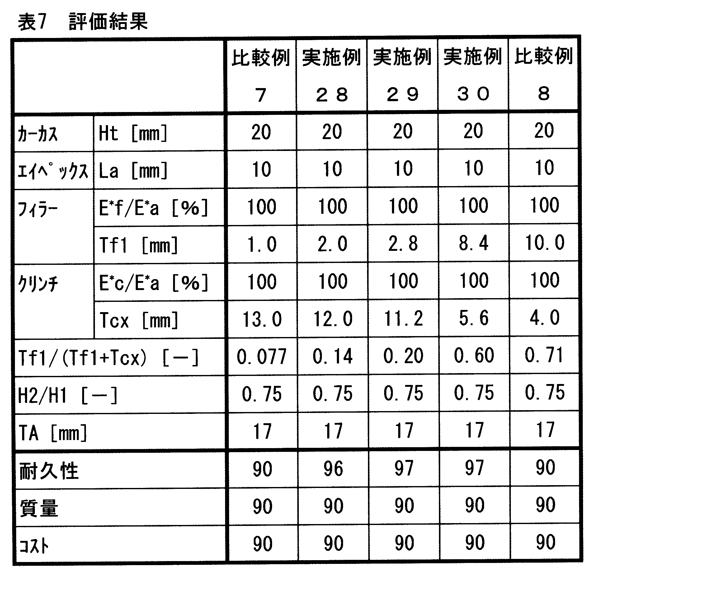
表1から7に示されるように、実施例のタイヤでは、比較例のタイヤに比べて評価が高い。この評価結果から、本発明の優位性は明らかである。なお、比較例3及び8では、耐久性の評価後、外観を観察したところ、折返し部の端においてルース(プライターンルース(PTL)が発生していることが確認された。
As shown in Tables 1 to 7, the tire of the example has a higher evaluation than the tire of the comparative example. From this evaluation result, the superiority of the present invention is clear. In Comparative Examples 3 and 8, the appearance was observed after evaluating the durability, and it was confirmed that loose (ply turn loose (PTL) was generated at the end of the folded portion.
[実験2]
[実施例101]
図3-5に示されたタイヤを製作した。このタイヤの諸元が表8に示されている。このタイヤのサイズは、LT265/75R16Cである。「HTU」構造のカーカスが採用された。断面高さHsは200mmであり、断面高さHsに対する折返し部の高さHtの比(Ht/Hs)は0.50であった。バンドの隙間の幅TDは一定とされた。エイペックスの複素弾性率E*a及びフィラーの複素弾性率E*fは、ともに40MPaとされた。フィラーの長さLaは、40mmとされた。クリンチの高さHcは、50mmとされた。クリンチの複素弾性率E*cは、32MPaとされた。比(H2/H1)は0.75であった。厚さTAは14mmであった。 [Experiment 2]
[Example 101]
The tire shown in Fig. 3-5 was manufactured. Table 8 shows the specifications of the tire. The size of this tire is LT265 / 75R16C. A carcass of “HTU” structure was adopted. The cross-sectional height Hs was 200 mm, and the ratio (Ht / Hs) of the folded portion height Ht to the cross-sectional height Hs was 0.50. The width TD of the gap between the bands was constant. The complex elastic modulus E * a of the apex and the complex elastic modulus E * f of the filler were both set to 40 MPa. The filler length La was 40 mm. The height Hc of the clinch was 50 mm. The complex elastic modulus E * c of clinch was set to 32 MPa. The ratio (H2 / H1) was 0.75. The thickness TA was 14 mm.
[比較例101]
比較例101のタイヤは、フィラーを有していない。このタイヤは従来のビードを備える。また、このタイヤのバンドには、テープの断面間に隙間は設けられていない。これらの他は実施例101と同様にしたのが、比較例101のタイヤである。このタイヤは、従来のタイヤである。 [Comparative Example 101]
The tire of Comparative Example 101 has no filler. This tire has a conventional bead. Further, no gap is provided between the cross sections of the tape in the tire band. The tire of Comparative Example 101 is the same as Example 101 except these. This tire is a conventional tire.
[比較例102]
バンドのテープの断面間に隙間が設けられていないことの他は実施例101と同様にしたのが、比較例102のタイヤである。 [Comparative Example 102]
The tire of Comparative Example 102 is the same as Example 101 except that no gap is provided between the cross sections of the band tapes.
バンドのテープの断面間に隙間が設けられていないことの他は実施例101と同様にしたのが、比較例102のタイヤである。 [Comparative Example 102]
The tire of Comparative Example 102 is the same as Example 101 except that no gap is provided between the cross sections of the band tapes.
[比較例103]
フィラーを有さず従来のビードを備えることの他は実施例101と同様にしたのが、比較例103のタイヤである。 [Comparative Example 103]
The tire of Comparative Example 103 is the same as Example 101 except that it has a conventional bead without a filler.
フィラーを有さず従来のビードを備えることの他は実施例101と同様にしたのが、比較例103のタイヤである。 [Comparative Example 103]
The tire of Comparative Example 103 is the same as Example 101 except that it has a conventional bead without a filler.
[実施例102-106]
隙間の幅TDを下記の表9の通りとした他は実施例101と同様にして、実施例102-106のタイヤを得た。 [Examples 102-106]
Tires of Examples 102 to 106 were obtained in the same manner as Example 101 except that the gap width TD was changed as shown in Table 9 below.
隙間の幅TDを下記の表9の通りとした他は実施例101と同様にして、実施例102-106のタイヤを得た。 [Examples 102-106]
Tires of Examples 102 to 106 were obtained in the same manner as Example 101 except that the gap width TD was changed as shown in Table 9 below.
[実施例107-111]
テープの幅TWを下記の表10の通りとした他は実施例101と同様にして、実施例107-111のタイヤを得た。 [Examples 107 to 111]
Tires of Examples 107 to 111 were obtained in the same manner as Example 101 except that the tape width TW was changed as shown in Table 10 below.
テープの幅TWを下記の表10の通りとした他は実施例101と同様にして、実施例107-111のタイヤを得た。 [Examples 107 to 111]
Tires of Examples 107 to 111 were obtained in the same manner as Example 101 except that the tape width TW was changed as shown in Table 10 below.
[実施例112-115及び比較例104-105]
フィラーの複素弾性率E*fを調整して百分比(E*f/E*a)を下記の表11の通りとした他は実施例101と同様にして、実施例112-115及び比較例104-105のタイヤを得た。 [Examples 112-115 and Comparative Examples 104-105]
Examples 112-115 and Comparative Example 104 were the same as Example 101 except that the complex elastic modulus E * f of the filler was adjusted so that the percentage (E * f / E * a) was as shown in Table 11 below. -105 tires were obtained.
[実施例116-119]
厚さTcx及び厚さTf1を調整して比(Tf1/(Tf1+Tcx))を下記の表12の通りとした他は実施例101と同様にして、実施例116-119のタイヤを得た。 [Examples 116 to 119]
Tires of Examples 116 to 119 were obtained in the same manner as in Example 101 except that the ratio (Tf1 / (Tf1 + Tcx)) was adjusted as shown in Table 12 below by adjusting the thickness Tcx and the thickness Tf1.
[耐フラットスポット性]
試作タイヤをリム(サイズ:7.5J)に装着して、このタイヤのラジアルフォースバリエーション(RFV)をJASO C607に準拠して計測した。この計測値は、タイヤの初期のRFV(F0)である。次に、ドラム試験機を用いて、予備的に1時間、このタイヤを60km/hの速度で走行させた。この走行時のタイヤの空気内圧は550kPaであり、荷重は18.75kNである。次に、このタイヤが、静止状態で16時間放置された。この放置のときのタイヤの空気内圧は550kPaであり、荷重は、18.75kNである。この放置により、このタイヤにフラットスポットが生成された。次に、このフラットスポットが生成されたタイヤについて、JASO C607に準拠してRFVを計測した。この計測値は、フラットスポット生成時のRFV(F1)である。次に、フラットスポットが生成されたタイヤを、前述の走行条件で、6分間走行させて、フラットスポットの回復が実施された。この回復走行後のタイヤについて、RFVが計測された。この計測値は、フラットスポットの回復後のRFV(F2)である。このF2をこのF1から差し引くことにより、RFVの回復量が算出された。この結果が、比較例101の回復量を100とした指数値で表8-12に示されている。 [Flat spot resistance]
The prototype tire was mounted on a rim (size: 7.5 J), and the radial force variation (RFV) of the tire was measured according to JASO C607. This measured value is the initial RFV (F0) of the tire. Next, the tire was run at a speed of 60 km / h for 1 hour using a drum testing machine. The tire has an internal air pressure of 550 kPa and a load of 18.75 kN. Next, the tire was left standing for 16 hours. The air pressure inside the tire at this time is 550 kPa, and the load is 18.75 kN. By this standing, a flat spot was generated on the tire. Next, RFV was measured based on JASO C607 for the tire in which this flat spot was generated. This measured value is RFV (F1) at the time of flat spot generation. Next, the flat spot was recovered by running the tire on which the flat spot was generated for 6 minutes under the above-described running conditions. RFV was measured for the tire after this recovery running. This measured value is RFV (F2) after flat spot recovery. The recovery amount of RFV was calculated by subtracting F2 from F1. The results are shown in Table 8-12 as index values with the recovery amount of Comparative Example 101 as 100.
[高速耐久性]
ECE30の規格に準拠して、高速耐久性の評価を行った。試作タイヤに損傷が生じた速度(km/h)を得た。この結果が、比較例101の速度を100とした指数値で表8-12に示されている。値が大きいほど、高速耐久性に優れていることを表している。 [High-speed durability]
High-speed durability was evaluated in accordance with the ECE30 standard. A speed (km / h) at which the prototype tire was damaged was obtained. The results are shown in Table 8-12 as index values with the speed of Comparative Example 101 as 100. The larger the value, the better the high-speed durability.
[耐久性]
タイヤを正規リム(サイズ=7.5J)に組み込み、このタイヤに空気を充填して内圧を550kPaとした。このタイヤをドラム式走行試験機に装着し、18.75kNの縦荷重をタイヤに負荷した。このタイヤを、80km/hの速度で、半径が1.7mであるドラムの上を走行させた。タイヤが破壊するまでの走行距離を、測定した。この結果が、比較例101を100とした指数として、下記の表8から12に示されている。数値が大きいほど、好ましい。この数値が95以上であることが、合格の目安である。 [durability]
The tire was incorporated into a regular rim (size = 7.5 J), and the tire was filled with air to adjust the internal pressure to 550 kPa. This tire was mounted on a drum-type running test machine, and a longitudinal load of 18.75 kN was applied to the tire. This tire was run on a drum having a radius of 1.7 m at a speed of 80 km / h. The distance traveled until the tire broke was measured. The results are shown in Tables 8 to 12 below as indices with Comparative Example 101 as 100. A larger numerical value is preferable. A numerical value of 95 or more is a measure of success.
[成形時間]
タイヤの成形工程で要した時間が計測された。この結果の逆数が、比較例101を100とした指数として、下記の表8から12に示されている。数値が小さいほど、好ましい。 [Molding time]
The time required for the tire molding process was measured. The reciprocal of this result is shown in the following Tables 8 to 12 as an index with the comparative example 101 as 100. The smaller the value, the better.

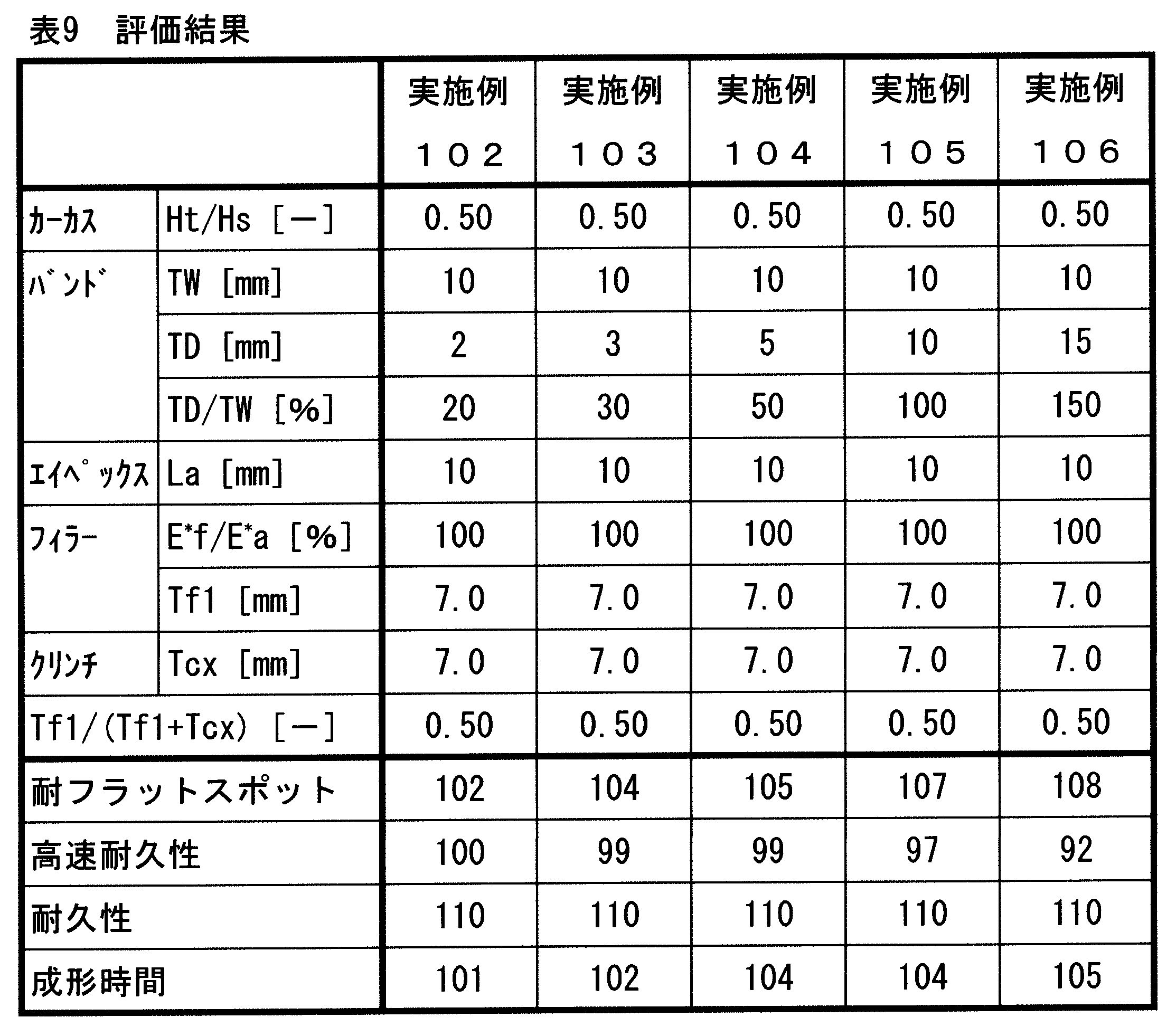


表8から12に示されるように、実施例のタイヤでは、比較例のタイヤに比べて評価が高い。この評価結果から、本発明の優位性は明らかである。
As shown in Tables 8 to 12, the tire of the example has a higher evaluation than the tire of the comparative example. From this evaluation result, the superiority of the present invention is clear.
[実験3]
[実施例201]
図6及び7に示されたタイヤを製作した。このタイヤの諸元が表13に示されている。このタイヤのサイズは、「LT265/75R16 123/120Q」である。断面高さHsは200mmであり、断面高さHsに対する折返し部の高さHtの比(Ht/Hs)は0.50であった。エイペックスの複素弾性率E*a及びフィラーの複素弾性率E*fは、ともに40MPaとされた。クリンチの複素弾性率E*cは、32MPaとされた。比(H2/H1)は0.75であった。 [Experiment 3]
[Example 201]
The tire shown in FIGS. 6 and 7 was produced. Table 13 shows the specifications of the tire. The size of this tire is “LT265 / 75R16 123 / 120Q”. The cross-sectional height Hs was 200 mm, and the ratio (Ht / Hs) of the folded portion height Ht to the cross-sectional height Hs was 0.50. The complex elastic modulus E * a of the apex and the complex elastic modulus E * f of the filler were both set to 40 MPa. The complex elastic modulus E * c of clinch was set to 32 MPa. The ratio (H2 / H1) was 0.75.
[比較例201]
比較例201のタイヤは、フィラーを有していない。このタイヤは、従来の市販タイヤである。その他は実施例201と同様の構成を備えていた。 [Comparative Example 201]
The tire of Comparative Example 201 does not have a filler. This tire is a conventional commercial tire. The other configurations were the same as in Example 201.
比較例201のタイヤは、フィラーを有していない。このタイヤは、従来の市販タイヤである。その他は実施例201と同様の構成を備えていた。 [Comparative Example 201]
The tire of Comparative Example 201 does not have a filler. This tire is a conventional commercial tire. The other configurations were the same as in Example 201.
[比較例202-203]
表13に示される様に、金型が変更され、初期クリップ幅Wc及び初期トレッド幅Wtが変更された他は、実施例201と同様にして、タイヤが得られた。 [Comparative Example 202-203]
As shown in Table 13, a tire was obtained in the same manner as in Example 201 except that the mold was changed and the initial clip width Wc and the initial tread width Wt were changed.
表13に示される様に、金型が変更され、初期クリップ幅Wc及び初期トレッド幅Wtが変更された他は、実施例201と同様にして、タイヤが得られた。 [Comparative Example 202-203]
As shown in Table 13, a tire was obtained in the same manner as in Example 201 except that the mold was changed and the initial clip width Wc and the initial tread width Wt were changed.
[実施例202-204]
表14に示される様に、金型が変更され、初期クリップ幅Wc及び初期トレッド幅Wtが変更された他は、実施例201と同様にして、タイヤを得た。 [Examples 202-204]
As shown in Table 14, a tire was obtained in the same manner as in Example 201 except that the mold was changed and the initial clip width Wc and the initial tread width Wt were changed.
表14に示される様に、金型が変更され、初期クリップ幅Wc及び初期トレッド幅Wtが変更された他は、実施例201と同様にして、タイヤを得た。 [Examples 202-204]
As shown in Table 14, a tire was obtained in the same manner as in Example 201 except that the mold was changed and the initial clip width Wc and the initial tread width Wt were changed.
[実施例205-206]
エイペックスの長さLaが、表14に示される様にされた他は、実施例203と同様にして、タイヤを得た。 [Examples 205-206]
A tire was obtained in the same manner as in Example 203 except that the length La of the apex was changed as shown in Table 14.
エイペックスの長さLaが、表14に示される様にされた他は、実施例203と同様にして、タイヤを得た。 [Examples 205-206]
A tire was obtained in the same manner as in Example 203 except that the length La of the apex was changed as shown in Table 14.
[実施例207]
フィラーの長さLfが表15に示される様にされた他は、実施例203と同様にして、タイヤを得た。 [Example 207]
A tire was obtained in the same manner as in Example 203 except that the filler length Lf was set as shown in Table 15.
フィラーの長さLfが表15に示される様にされた他は、実施例203と同様にして、タイヤを得た。 [Example 207]
A tire was obtained in the same manner as in Example 203 except that the filler length Lf was set as shown in Table 15.
[実施例208]
クリンチの高さHcが表15に示される様にされた他は、実施例203と同様にして、タイヤを得た。 [Example 208]
A tire was obtained in the same manner as in Example 203 except that the clinch height Hc was set as shown in Table 15.
クリンチの高さHcが表15に示される様にされた他は、実施例203と同様にして、タイヤを得た。 [Example 208]
A tire was obtained in the same manner as in Example 203 except that the clinch height Hc was set as shown in Table 15.
[実施例209-210]
クリンチの高さHc及び厚さTcxが変更された。厚さTcx及び厚さTf1を調整して比(Tf1/(Tf1+Tcx))を下記の表15の通りとした。その他は実施例203と同様にして、タイヤを得た。 [Examples 209-210]
The height Hc and thickness Tcx of the clinch were changed. The ratio (Tf1 / (Tf1 + Tcx)) was adjusted as shown in Table 15 below by adjusting the thickness Tcx and the thickness Tf1. Others were the same as in Example 203, and a tire was obtained.
[耐久性]
タイヤを正規リム(サイズ=7.5J)に組み込み、このタイヤに空気を充填して内圧を550kPaとした。このタイヤをドラム式走行試験機に装着し、18.75kNの縦荷重をタイヤに負荷した。このタイヤを、80km/hの速度で、半径が1.7mであるドラムの上を走行させた。タイヤが破壊するまでの走行距離を、測定した。この結果が、比較例201を100とした指数として、表13から15に示されている。数値が大きいほど、好ましい。この数値が95以上であることが、合格の目安である。 [durability]
The tire was incorporated into a regular rim (size = 7.5 J), and the tire was filled with air to adjust the internal pressure to 550 kPa. This tire was mounted on a drum-type running test machine, and a longitudinal load of 18.75 kN was applied to the tire. This tire was run on a drum having a radius of 1.7 m at a speed of 80 km / h. The distance traveled until the tire broke was measured. The results are shown in Tables 13 to 15 as indices with the comparative example 201 as 100. A larger numerical value is preferable. A numerical value of 95 or more is a measure of success.
[質量評価]
タイヤ単体の質量が測定された。比較例201のタイヤの質量を100として、それぞれのタイヤの質量の指数が表13から15に示されている。この指数は大きいほど質量が大きく、この指数は、小さいほど好ましい。 [Mass evaluation]
The mass of the tire alone was measured. The index of the mass of each tire is shown in Tables 13 to 15 where the mass of the tire of Comparative Example 201 is 100. The larger the index, the larger the mass, and the smaller the index, the better.
[製造コスト評価]
タイヤの成形工程で要した時間が計測された。この結果の逆数が、比較例201を100とした指数として、下記の表13から15に示されている。数値が小さいほど、好ましい。 [Production cost evaluation]
The time required for the tire molding process was measured. The reciprocal of this result is shown in the following Tables 13 to 15 as an index with the comparative example 201 as 100. The smaller the value, the better.
[エアーイン性評価]
これらのタイヤが、このタイヤの軸方向を上下方向にして、積み上げられた。評価用タイヤの上に同じタイヤを7本積み上げた。この状態を2週間保持した。その後、評価用タイヤが正規リム(サイズ:7.5J)に装着されて、空気が充填された。空気を充填したときに、ビード部がリムのフランジに当接して適正な位置に配置されるか否かが評価された。評価用タイヤがそのままの状態で、リム組みされて、適正に空気が充填できた場合は「良」とした。そのままの状態では潰れ具合が大きく空気が十分に充填できなければ「不良」とした。その結果が表13から15に示されている。 [Air-in evaluation]
These tires were stacked with the axial direction of the tire being the vertical direction. Seven of the same tires were stacked on the evaluation tire. This state was maintained for 2 weeks. Thereafter, an evaluation tire was mounted on a regular rim (size: 7.5 J) and filled with air. When filled with air, it was evaluated whether or not the bead portion was in contact with the flange of the rim and placed at an appropriate position. If the rim was assembled with the evaluation tire as it was and the air could be filled properly, it was judged as “good”. In the state as it is, if the degree of crushing was large and air could not be sufficiently filled, it was judged as “defective”. The results are shown in Tables 13-15.


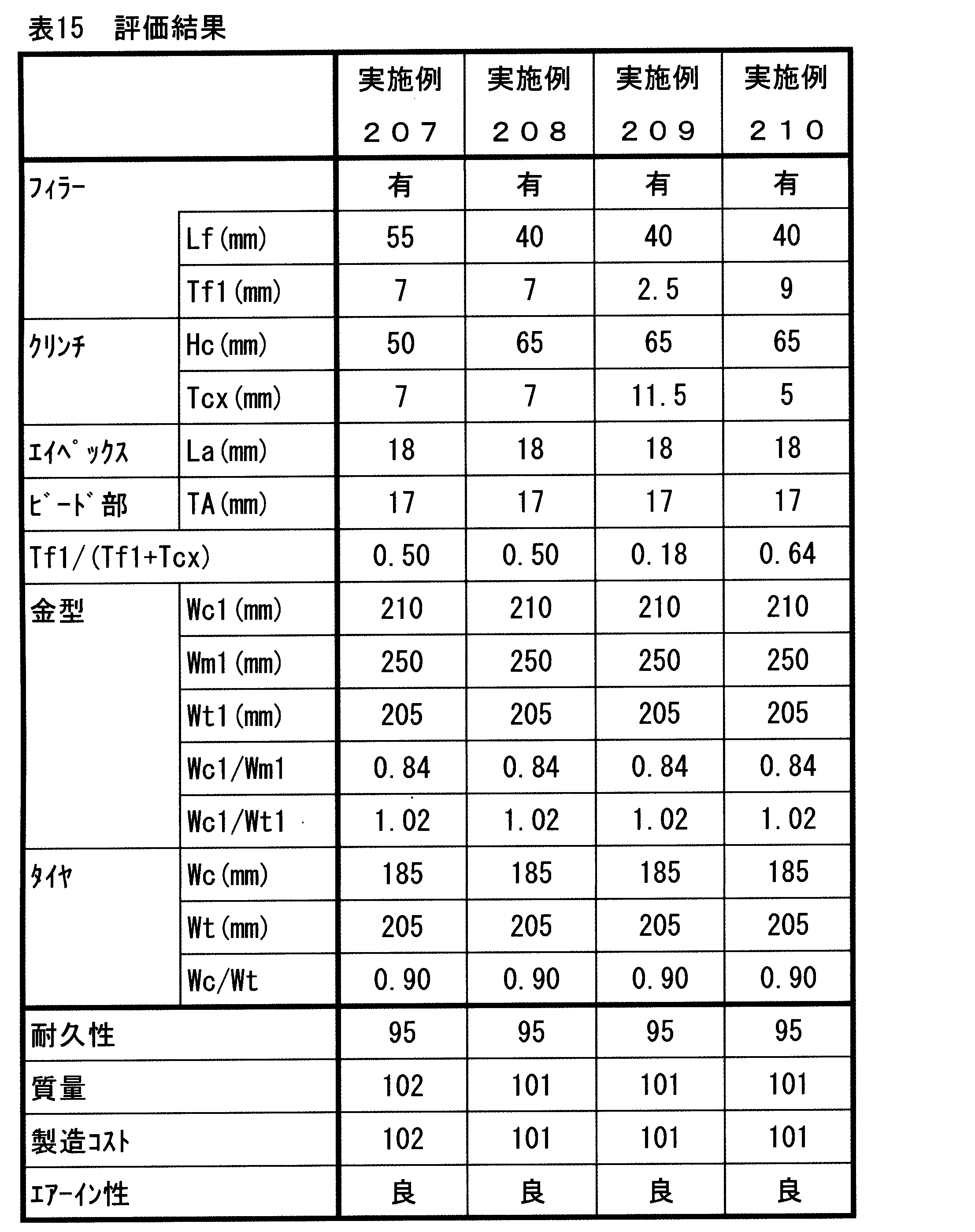
表13から15に示されるように、実施例のタイヤでは、比較例のタイヤに比べて評価が高い。この評価結果から、本発明の優位性は明らかである。
As shown in Tables 13 to 15, the tire of the example has a higher evaluation than the tire of the comparative example. From this evaluation result, the superiority of the present invention is clear.
以上説明されたフィラーに関する技術は、種々の車輌のためのタイヤにも適用されうる。
The filler-related technology described above can be applied to tires for various vehicles.
2、102、202・・・タイヤ
4、104、204・・・トレッド
6、106、206・・・サイドウォール
8、108、208・・・クリンチ
10、110、210・・・フィラー
12、112、212・・・ビード
14、114、214・・・カーカス
34、134、234・・・クリンチの外端
36、136、236・・・サイドウォールの内端
38、138、238・・・フィラーの内端
40、140、240・・・クリンチの内端
42、142、242・・・フィラーの外端
44、144、244・・・コア
46、146、246・・・エイペックス
48、148、248・・・エイペックスの先端
50、150、250・・・第一カーカスプライ
50a、150a、250a・・・第一主部
50b、150b、250b・・・第一折返し部
52、152、252・・・第二カーカスプライ
52a、152a、152a・・・第二主部
54、154、254・・・第一折返し部の端
56、156、256・・・第二カーカスプライの端
120、220・・・バンド
162・・・断面
164・・・隙間
262・・・金型
264・・・ブラダー
266・・・トレッドセグメント
268・・・上部サイドプレート
270・・・下部サイドプレート
272・・・上部ビードリング
274・・・下部ビードリング 2, 102, 202 ... tire 4, 104, 204 ... tread 6, 106, 206 ... sidewall 8, 108, 208 ... clinch 10, 110, 210 ... filler 12, 112, 212 ... Bead 14, 114, 214 ... Carcass 34, 134, 234 ... Clinch outer end 36, 136, 236 ... Side wall inner end 38, 138, 238 ... Inside filler End 40, 140, 240 ... Clinch inner end 42, 142, 242 ... Filler outer end 44, 144, 244 ... Core 46, 146, 246 ... Apex 48, 148, 248 .. Apex tips 50, 150, 250 ... first carcass ply 50a, 150a, 250a ... first main part 50b, 150b, 2 0b: first folded portion 52, 152, 252 ... second carcass ply 52a, 152a, 152a ... second main portion 54, 154, 254 ... end of first folded portion 56, 156, 256 ... end of second carcass ply 120, 220 ... band 162 ... cross section 164 ... gap 262 ... mold 264 ... bladder 266 ... tread segment 268 ... upper side Plate 270 ... Lower side plate 272 ... Upper bead ring 274 ... Lower bead ring
4、104、204・・・トレッド
6、106、206・・・サイドウォール
8、108、208・・・クリンチ
10、110、210・・・フィラー
12、112、212・・・ビード
14、114、214・・・カーカス
34、134、234・・・クリンチの外端
36、136、236・・・サイドウォールの内端
38、138、238・・・フィラーの内端
40、140、240・・・クリンチの内端
42、142、242・・・フィラーの外端
44、144、244・・・コア
46、146、246・・・エイペックス
48、148、248・・・エイペックスの先端
50、150、250・・・第一カーカスプライ
50a、150a、250a・・・第一主部
50b、150b、250b・・・第一折返し部
52、152、252・・・第二カーカスプライ
52a、152a、152a・・・第二主部
54、154、254・・・第一折返し部の端
56、156、256・・・第二カーカスプライの端
120、220・・・バンド
162・・・断面
164・・・隙間
262・・・金型
264・・・ブラダー
266・・・トレッドセグメント
268・・・上部サイドプレート
270・・・下部サイドプレート
272・・・上部ビードリング
274・・・下部ビードリング 2, 102, 202 ...
Claims (18)
- トレッド、一対のサイドウォール、一対のクリンチ、一対のフィラー、一対のビード及びカーカスを備えており、
それぞれのサイドウォールが、上記トレッドの端から半径方向略内向きに延びており、
それぞれのクリンチが、上記サイドウォールよりも半径方向内側に位置しており、
それぞれのフィラーが、上記クリンチよりも軸方向内側に位置しており、
それぞれのビードが、上記フィラーよりも半径方向内側に位置しており、
上記カーカスが、上記トレッド及び上記サイドウォールの内側に沿って一方のビードと他方のビードとの間に架け渡されており、
上記フィラーが、上記カーカスの軸方向外側において、上記クリンチと積層されており、
上記ビードが、コアと、このコアから半径方向外向きに延びるエイペックスとを備えており、
上記カーカスがカーカスプライを備えており、
上記カーカスプライが上記コアの周りにて軸方向内側から外側に向かって折り返されており、この折り返しによりこのカーカスプライには主部と折返し部とが形成されており、
上記折返し部が、上記フィラーと上記エイペックスとの間に位置しており、
上記クリンチが、このクリンチの軸方向内面の法線に沿って計測される、最大の厚さTcxを有しており、
上記厚さTcxのための法線を第一基準線としたとき、
この第一基準線に沿って計測される上記フィラーの厚さTf1の、この厚さTf1及びこの厚さTcxの和に対する比が、0.1以上0.6以下であり、
上記エイペックスの複素弾性率E*aに対する上記フィラーの複素弾性率E*fの百分比が70%以上125%以下である、空気入りタイヤ。 It has a tread, a pair of sidewalls, a pair of clinch, a pair of fillers, a pair of beads and a carcass,
Each sidewall extends radially inward from the end of the tread,
Each clinch is located radially inward from the sidewall,
Each filler is located on the inner side in the axial direction than the clinch,
Each bead is located radially inward of the filler,
The carcass is stretched between one bead and the other bead along the inside of the tread and the sidewall,
The filler is laminated with the clinch on the outside in the axial direction of the carcass,
The bead includes a core and an apex extending radially outward from the core;
The carcass has a carcass ply,
The carcass ply is folded from the inner side to the outer side in the axial direction around the core, and by this folding, a main part and a folded part are formed in the carcass ply,
The folded portion is located between the filler and the apex,
The clinch has a maximum thickness Tcx, measured along the normal of the axial inner surface of the clinch;
When the normal for the thickness Tcx is the first reference line,
The ratio of the thickness Tf1 of the filler measured along the first reference line to the sum of the thickness Tf1 and the thickness Tcx is 0.1 or more and 0.6 or less,
A pneumatic tire, wherein the percentage of the complex elastic modulus E * f of the filler to the complex elastic modulus E * a of the apex is 70% or more and 125% or less. - 上記フィラーが、上記クリンチの軸方向内面の法線に沿って計測される、最大の厚さTfxを有しており、
この厚さTfxのための法線を第二基準線としたとき、
このフィラーの内端から、この第二基準線と上記クリンチの軸方向内面との交点までの半径方向長さの、このフィラーの内端から、上記第一基準線とこのクリンチの軸方向内面との交点までの半径方向長さに対する比が、0.6以上1.2以下である、請求項1に記載の空気入りタイヤ。 The filler has a maximum thickness Tfx, measured along the normal of the axial inner surface of the clinch;
When the normal for this thickness Tfx is taken as the second reference line,
From the inner end of the filler to the intersection of the second reference line and the inner surface in the axial direction of the clinch, from the inner end of the filler, the first reference line and the inner surface in the axial direction of the clinch 2. The pneumatic tire according to claim 1, wherein a ratio to a length in a radial direction up to an intersection is 0.6 or more and 1.2 or less. - 上記フィラーの複素弾性率E*fに対する上記クリンチの複素弾性率E*cの百分比が、70%以上125%以下である、請求項1又は2に記載の空気入りタイヤ。 The pneumatic tire according to claim 1 or 2, wherein a percentage of the complex elastic modulus E * c of the clinch to the complex elastic modulus E * f of the filler is 70% or more and 125% or less.
- 上記第一基準線に沿って計測されるこのタイヤの厚みが10mm以上20mm以下である、請求項1から3のいずれかに記載の空気入りタイヤ。 The pneumatic tire according to any one of claims 1 to 3, wherein a thickness of the tire measured along the first reference line is 10 mm or more and 20 mm or less.
- トレッド、一対のサイドウォール、一対のクリンチ、一対のフィラー、一対のビード、カーカス、及びバンドを備えており、
それぞれのサイドウォールが、上記トレッドの端から半径方向略内向きに延びており、
それぞれのクリンチが、上記サイドウォールよりも半径方向内側に位置しており、
それぞれのフィラーが、上記クリンチよりも軸方向内側に位置しており、
それぞれのビードが、上記フィラーよりも半径方向内側に位置しており、
上記カーカスが、上記トレッド及び上記サイドウォールの内側に沿って一方のビードと他方のビードとの間に架け渡されており、
上記フィラーが、上記カーカスの軸方向外側において、上記クリンチと積層されており、
上記バンドが、半径方向において上記カーカスの外側で上記トレッドの内側に位置しており、
上記ビードが、コアと、このコアから半径方向外向きに延びるエイペックスとを備えており、
上記カーカスがカーカスプライを備えており、
上記カーカスプライが上記コアの周りにて軸方向内側から外側に向かって折り返されており、この折り返しによりこのカーカスプライには主部と折返し部とが形成されており、
上記折返し部が、上記フィラーと上記エイペックスとの間に位置しており、
上記エイペックスの複素弾性率E*aに対する上記フィラーの複素弾性率E*fの百分比が70%以上125%以下であり、
上記バンドが、長さ方向に延在するコードを備えたテープを略周方向に螺旋状に巻回すことで構成されており、これによりこのタイヤの周方向に垂直な面で切った断面において、上記テープの断面が軸方向に並んでおり、
上記テープの隣接する上記断面間に隙間が設けられている空気入りタイヤ。 It includes a tread, a pair of sidewalls, a pair of clinch, a pair of fillers, a pair of beads, a carcass, and a band.
Each sidewall extends radially inward from the end of the tread,
Each clinch is located radially inward from the sidewall,
Each filler is located on the inner side in the axial direction than the clinch,
Each bead is located radially inward of the filler,
The carcass is stretched between one bead and the other bead along the inside of the tread and the sidewall,
The filler is laminated with the clinch on the outside in the axial direction of the carcass,
The band is located outside the carcass in the radial direction and inside the tread;
The bead includes a core and an apex extending radially outward from the core;
The carcass has a carcass ply,
The carcass ply is folded from the inner side to the outer side in the axial direction around the core, and by this folding, a main part and a folded part are formed in the carcass ply,
The folded portion is located between the filler and the apex,
The percentage of the complex elastic modulus E * f of the filler to the complex elastic modulus E * a of the apex is 70% or more and 125% or less,
The band is configured by spirally winding a tape with a cord extending in the length direction in a substantially circumferential direction, and in a cross section cut by a plane perpendicular to the circumferential direction of the tire, The cross section of the tape is aligned in the axial direction,
A pneumatic tire in which a gap is provided between adjacent sections of the tape. - 上記テープの幅TWが9mm以上15mm以下であり、上記隙間の幅TDが3mm以上9mm以下である請求項5に記載の空気入りタイヤ。 The pneumatic tire according to claim 5, wherein a width TW of the tape is 9 mm or more and 15 mm or less, and a width TD of the gap is 3 mm or more and 9 mm or less.
- 上記クリンチが、このクリンチの軸方向内面の法線に沿って計測される、最大の厚さTcxを有しており、
上記厚さTcxのための法線を第一基準線としたとき、
この第一基準線に沿って計測される上記フィラーの厚さTf1の、この厚さTf1及びこの厚さTcxの和に対する比が、0.1以上0.6以下である、請求項5又は6に空気入りタイヤ。 The clinch has a maximum thickness Tcx, measured along the normal of the axial inner surface of the clinch;
When the normal for the thickness Tcx is the first reference line,
The ratio of the thickness Tf1 of the filler measured along the first reference line to the sum of the thickness Tf1 and the thickness Tcx is 0.1 or more and 0.6 or less. Pneumatic tires. - 上記フィラーが、上記クリンチの軸方向内面の法線に沿って計測される、最大の厚さTfxを有しており、
この厚さTfxのための法線を第二基準線としたとき、
このフィラーの内端から、この第二基準線と上記クリンチの軸方向内面との交点までの半径方向長さの、このフィラーの内端から、上記第一基準線とこのクリンチの軸方向内面との交点までの半径方向長さに対する比が、0.6以上1.2以下である、請求項5から7のいずれかに記載の空気入りタイヤ。 The filler has a maximum thickness Tfx, measured along the normal of the axial inner surface of the clinch;
When the normal for this thickness Tfx is taken as the second reference line,
From the inner end of the filler to the intersection of the second reference line and the inner surface in the axial direction of the clinch, from the inner end of the filler, the first reference line and the inner surface in the axial direction of the clinch The pneumatic tire according to any one of claims 5 to 7, wherein a ratio to a length in a radial direction up to an intersection is 0.6 or more and 1.2 or less. - 上記フィラーの複素弾性率E*fに対する上記クリンチの複素弾性率E*cの百分比が、70%以上125%以下である、請求項5から8のいずれかに記載の空気入りタイヤ。 The pneumatic tire according to any one of claims 5 to 8, wherein a percentage of the complex elastic modulus E * c of the clinch to the complex elastic modulus E * f of the filler is 70% or more and 125% or less.
- 上記第一基準線に沿って計測されるこのタイヤの厚みが10mm以上20mm以下である、請求項5から9のいずれかに記載の空気入りタイヤ。 The pneumatic tire according to any one of claims 5 to 9, wherein a thickness of the tire measured along the first reference line is 10 mm or more and 20 mm or less.
- トレッド、一対のサイドウォール、一対のクリンチ、一対のフィラー、一対のビード及びカーカスを備えており、
それぞれのサイドウォールが、上記トレッドの端から半径方向略内向きに延びており、
それぞれのクリンチが、上記サイドウォールの半径方向内側に位置しており、
それぞれのフィラーが、上記クリンチの軸方向内側に位置しており、このフィラーが、上記カーカスの軸方向外側において、上記クリンチと積層されており、このフィラーの軸方向内面が内側に突出する向きに湾曲しており、
それぞれのビードが、上記フィラーの半径方向内側に位置しており、上記ビードが、コアと、このコアから半径方向外向きに延びるエイペックスとを備えており、
上記カーカスが、上記トレッド及び上記サイドウォールの内側に沿って一方のビードと他方のビードとの間に架け渡されており、
上記カーカスがカーカスプライを備えており、
上記カーカスプライが上記コアの周りにて軸方向内側から外側に向かって折り返されており、この折り返しによりこのカーカスプライには主部と折返し部とが形成されており、
上記折返し部が、上記フィラーと上記エイペックスとの間に位置しており、
上記クリンチが、このクリンチの軸方向内面の法線に沿って計測される、最大の厚さTcxを有しており、
上記厚さTcxのための法線を第一基準線としたとき、第一基準線とフィラーの軸方向内面との交点PFが、第一基準線で測定されるタイヤの厚さTAの中点より軸方向内側に位置しており、
加硫成形でこのタイヤを得るために用いられる金型において、
この金型の最大幅Wm1に対するこの金型のクリップ幅Wc1の比が0.80以上0.90以下であり、この金型のトレッド幅Wt1に対するこの金型のクリップ幅Wc1の比が0.95以上1.10以下である、空気入りタイヤ。 It has a tread, a pair of sidewalls, a pair of clinch, a pair of fillers, a pair of beads and a carcass,
Each sidewall extends radially inward from the end of the tread,
Each clinch is located radially inside the sidewall,
Each filler is positioned on the inner side in the axial direction of the clinch, the filler is laminated with the clinch on the outer side in the axial direction of the carcass, and the inner surface in the axial direction of the filler protrudes inward. Curved,
Each bead is located radially inward of the filler, the bead comprising a core and an apex extending radially outward from the core;
The carcass is stretched between one bead and the other bead along the inside of the tread and the sidewall,
The carcass has a carcass ply,
The carcass ply is folded from the inner side to the outer side in the axial direction around the core, and by this folding, a main part and a folded part are formed in the carcass ply,
The folded portion is located between the filler and the apex,
The clinch has a maximum thickness Tcx, measured along the normal of the axial inner surface of the clinch;
When the normal for the thickness Tcx is the first reference line, the intersection PF between the first reference line and the inner surface in the axial direction of the filler is the midpoint of the tire thickness TA measured at the first reference line. More axially inside,
In the mold used to obtain this tire by vulcanization molding,
The ratio of the clip width Wc1 of the mold to the maximum width Wm1 of the mold is 0.80 or more and 0.90 or less, and the ratio of the clip width Wc1 of the mold to the tread width Wt1 of the mold is 0.95. A pneumatic tire that is 1.10 or less. - 上記厚さTAが10mm以上20mm以下である請求項11に記載のタイヤ。 The tire according to claim 11, wherein the thickness TA is 10 mm or more and 20 mm or less.
- 上記エイペックスの長さLaが5mm以上20mm以下である請求項11又は12に記載のタイヤ。 The tire according to claim 11 or 12, wherein a length La of the apex is 5 mm or more and 20 mm or less.
- 上記第一基準線に沿って計測される上記フィラーの厚さTf1とこの厚さTcxとの和に対する、この厚さTf1の比が0.1以上0.6以下である、請求項11から13のいずれかに記載のタイヤ。 The ratio of the thickness Tf1 to the sum of the thickness Tf1 of the filler and the thickness Tcx measured along the first reference line is 0.1 or more and 0.6 or less. The tire according to any one of the above.
- 上記エイペックスの複素弾性率E*aに対する上記フィラーの複素弾性率E*fの百分比が70%以上125%以下である請求項11から14のいずれかに記載のタイヤ。 The tire according to any one of claims 11 to 14, wherein a percentage ratio of the complex elastic modulus E * f of the filler to the complex elastic modulus E * a of the apex is 70% or more and 125% or less.
- 上記フィラーが、上記クリンチの軸方向内面の法線に沿って計測される、最大の厚さTfxを有しており、
この厚さTfxのための法線を第二基準線としたとき、
このフィラーの内端から、この第二基準線と上記クリンチの軸方向内面との交点までの半径方向長さの、このフィラーの内端から、上記第一基準線とこのクリンチの軸方向内面との交点までの半径方向長さに対する比が、0.6以上1.2以下である、請求項11から15のいずれかに記載のタイヤ。 The filler has a maximum thickness Tfx, measured along the normal of the axial inner surface of the clinch;
When the normal for this thickness Tfx is taken as the second reference line,
From the inner end of the filler to the intersection of the second reference line and the inner surface in the axial direction of the clinch, from the inner end of the filler, the first reference line and the inner surface in the axial direction of the clinch The tire according to any one of claims 11 to 15, wherein a ratio to a length in a radial direction up to an intersection is 0.6 or more and 1.2 or less. - 上記フィラーの複素弾性率E*fに対する上記クリンチの複素弾性率E*cの百分比が、70%以上125%以下である、請求項11から16のいずれかに記載の空気入りタイヤ。 The pneumatic tire according to any one of claims 11 to 16, wherein a percentage of the complex elastic modulus E * c of the clinch to the complex elastic modulus E * f of the filler is 70% or more and 125% or less.
- トレッド、一対のサイドウォール、一対のクリンチ、一対のフィラー、一対のビード及びカーカスを備えており、
それぞれのサイドウォールが、上記トレッドの端から半径方向略内向きに延びており、
それぞれのクリンチが、上記サイドウォールの半径方向内側に位置しており、
それぞれのフィラーが、上記クリンチの軸方向内側に位置しており、このフィラーが、上記カーカスの軸方向外側において、上記クリンチと積層されており、このフィラーの軸方向内面が内側に突出する向きに湾曲しており、
それぞれのビードが、上記フィラーの半径方向内側に位置しており、上記ビードが、コアと、このコアから半径方向外向きに延びるエイペックスとを備えており、
上記カーカスが、上記トレッド及び上記サイドウォールの内側に沿って一方のビードと他方のビードとの間に架け渡されており、
上記カーカスがカーカスプライを備えており、
上記カーカスプライが上記コアの周りにて軸方向内側から外側に向かって折り返されており、この折り返しによりこのカーカスプライには主部と折返し部とが形成されており、
上記折返し部が、上記フィラーと上記エイペックスとの間に位置しており、
上記クリンチが、このクリンチの軸方向内面の法線に沿って計測される、最大の厚さTcxを有しており、
上記厚さTcxのための法線を第一基準線としたとき、第一基準線とフィラーの軸方向内面との交点PFが、第一基準線で測定されるタイヤの厚さTAの中点より軸方向内側に位置しており、
リム組みされる前の、初期のトレッド幅Wtに対する初期のクリップ幅Wcの比が0.90以上1.00以下である空気入りタイヤ。 It has a tread, a pair of sidewalls, a pair of clinch, a pair of fillers, a pair of beads and a carcass,
Each sidewall extends radially inward from the end of the tread,
Each clinch is located radially inside the sidewall,
Each filler is positioned on the inner side in the axial direction of the clinch, the filler is laminated with the clinch on the outer side in the axial direction of the carcass, and the inner surface in the axial direction of the filler protrudes inward. Curved,
Each bead is located radially inward of the filler, the bead comprising a core and an apex extending radially outward from the core;
The carcass is stretched between one bead and the other bead along the inside of the tread and the sidewall,
The carcass has a carcass ply,
The carcass ply is folded from the inner side to the outer side in the axial direction around the core, and by this folding, a main part and a folded part are formed in the carcass ply,
The folded portion is located between the filler and the apex,
The clinch has a maximum thickness Tcx, measured along the normal of the axial inner surface of the clinch;
When the normal for the thickness Tcx is the first reference line, the intersection PF between the first reference line and the inner surface in the axial direction of the filler is the midpoint of the tire thickness TA measured at the first reference line. More axially inside,
A pneumatic tire in which the ratio of the initial clip width Wc to the initial tread width Wt before assembly of the rim is 0.90 or more and 1.00 or less.
Priority Applications (4)
| Application Number | Priority Date | Filing Date | Title |
|---|---|---|---|
| EP20190415.8A EP3753755B1 (en) | 2014-09-04 | 2015-09-03 | Pneumatic tire |
| US15/508,682 US10759233B2 (en) | 2014-09-04 | 2015-09-03 | Pneumatic tire |
| EP15838987.4A EP3196055B1 (en) | 2014-09-04 | 2015-09-03 | Pneumatic tire |
| CN201580047530.4A CN106794718B (en) | 2014-09-04 | 2015-09-03 | Pneumatic tire |
Applications Claiming Priority (6)
| Application Number | Priority Date | Filing Date | Title |
|---|---|---|---|
| JP2014179768A JP6141243B2 (en) | 2014-09-04 | 2014-09-04 | Pneumatic tire |
| JP2014-179768 | 2014-09-04 | ||
| JP2014-198495 | 2014-09-29 | ||
| JP2014198495A JP6141246B2 (en) | 2014-09-29 | 2014-09-29 | Pneumatic tire |
| JP2014198131A JP6141245B2 (en) | 2014-09-29 | 2014-09-29 | Pneumatic tire |
| JP2014-198131 | 2014-09-29 |
Publications (1)
| Publication Number | Publication Date |
|---|---|
| WO2016035840A1 true WO2016035840A1 (en) | 2016-03-10 |
Family
ID=55439897
Family Applications (1)
| Application Number | Title | Priority Date | Filing Date |
|---|---|---|---|
| PCT/JP2015/075029 WO2016035840A1 (en) | 2014-09-04 | 2015-09-03 | Pneumatic tire |
Country Status (4)
| Country | Link |
|---|---|
| US (1) | US10759233B2 (en) |
| EP (2) | EP3753755B1 (en) |
| CN (3) | CN108608813B (en) |
| WO (1) | WO2016035840A1 (en) |
Cited By (2)
| Publication number | Priority date | Publication date | Assignee | Title |
|---|---|---|---|---|
| CN110167767A (en) * | 2017-03-10 | 2019-08-23 | 横滨橡胶株式会社 | Pneumatic tire and its manufacturing method |
| WO2022158086A1 (en) * | 2021-01-22 | 2022-07-28 | 株式会社ブリヂストン | Pneumatic tire |
Families Citing this family (19)
| Publication number | Priority date | Publication date | Assignee | Title |
|---|---|---|---|---|
| JP6718334B2 (en) | 2016-08-17 | 2020-07-08 | 株式会社ブリヂストン | Pneumatic tire |
| JP7024360B2 (en) * | 2017-02-08 | 2022-02-24 | 住友ゴム工業株式会社 | Heavy-duty tires and methods for manufacturing heavy-duty tires |
| EP3360699B1 (en) * | 2017-02-08 | 2019-12-04 | Sumitomo Rubber Industries, Ltd. | Heavy duty tire and and method for manufacturing the same |
| JP6956945B2 (en) * | 2017-08-09 | 2021-11-02 | 住友ゴム工業株式会社 | Pneumatic tires |
| JP6662366B2 (en) * | 2017-12-01 | 2020-03-11 | 横浜ゴム株式会社 | Pneumatic tire |
| US20200114701A1 (en) * | 2018-10-16 | 2020-04-16 | The Goodyear Tire & Rubber Company | Pneumatic tire |
| JP7154947B2 (en) * | 2018-10-26 | 2022-10-18 | Toyo Tire株式会社 | Pneumatic tire manufacturing method and bead member storage holder |
| US20200130416A1 (en) * | 2018-10-26 | 2020-04-30 | Toyo Tire Corporation | Pneumatic tire |
| JP7159793B2 (en) * | 2018-11-02 | 2022-10-25 | 横浜ゴム株式会社 | pneumatic tire |
| JP7119944B2 (en) * | 2018-11-26 | 2022-08-17 | 住友ゴム工業株式会社 | Pneumatic tires and vulcanization molds |
| JP7227847B2 (en) * | 2019-05-17 | 2023-02-22 | Toyo Tire株式会社 | tire |
| JP2020203613A (en) | 2019-06-18 | 2020-12-24 | 株式会社ブリヂストン | tire |
| JP7388056B2 (en) * | 2019-08-29 | 2023-11-29 | 住友ゴム工業株式会社 | pneumatic tires |
| JP7379979B2 (en) * | 2019-09-18 | 2023-11-15 | 住友ゴム工業株式会社 | Pneumatic tires for heavy loads |
| JP7380014B2 (en) * | 2019-09-26 | 2023-11-15 | 住友ゴム工業株式会社 | pneumatic tires |
| US20210094363A1 (en) * | 2019-09-30 | 2021-04-01 | The Goodyear Tire & Rubber Company | Sidewall construction for a tire |
| CN111361361A (en) * | 2020-04-20 | 2020-07-03 | 江苏通用科技股份有限公司 | Anti-static tire structure |
| JP2022149871A (en) | 2021-03-25 | 2022-10-07 | 住友ゴム工業株式会社 | pneumatic tire |
| CN114312166B (en) * | 2022-01-27 | 2024-01-09 | 青岛双星轮胎工业有限公司 | Apex and explosion-proof tire |
Citations (11)
| Publication number | Priority date | Publication date | Assignee | Title |
|---|---|---|---|---|
| JP2004224277A (en) * | 2003-01-24 | 2004-08-12 | Toyo Tire & Rubber Co Ltd | Pneumatic tire |
| JP2006213241A (en) * | 2005-02-04 | 2006-08-17 | Bridgestone Corp | Pneumatic tire |
| JP2007045333A (en) * | 2005-08-10 | 2007-02-22 | Sumitomo Rubber Ind Ltd | Pneumatic tire |
| JP2007210363A (en) * | 2006-02-07 | 2007-08-23 | Bridgestone Corp | Pneumatic tire |
| JP2008168702A (en) * | 2007-01-10 | 2008-07-24 | Sumitomo Rubber Ind Ltd | Pneumatic tire |
| JP2011011429A (en) * | 2009-07-01 | 2011-01-20 | Sumitomo Rubber Ind Ltd | Mold for retreaded tire, and method for manufacturing retreaded tire using the same |
| JP2012025280A (en) * | 2010-07-23 | 2012-02-09 | Bridgestone Corp | Pneumatic tire |
| JP2013056659A (en) * | 2011-09-06 | 2013-03-28 | Goodyear Tire & Rubber Co:The | Pneumatic tire |
| JP2013103478A (en) * | 2011-11-16 | 2013-05-30 | Sumitomo Rubber Ind Ltd | Raw cover |
| JP2013147065A (en) * | 2012-01-17 | 2013-08-01 | Sumitomo Rubber Ind Ltd | Pneumatic tire |
| WO2015129595A1 (en) * | 2014-02-26 | 2015-09-03 | 住友ゴム工業株式会社 | Pneumatic tire |
Family Cites Families (19)
| Publication number | Priority date | Publication date | Assignee | Title |
|---|---|---|---|---|
| DE3401016A1 (en) * | 1983-07-27 | 1985-02-14 | Jonny 4000 Düsseldorf Janus | BELT TIRES AND METHOD FOR PRODUCING THE SAME |
| JPH0399903A (en) * | 1989-09-14 | 1991-04-25 | Sumitomo Rubber Ind Ltd | Radial tire for heavy load |
| JP3138404B2 (en) * | 1995-02-27 | 2001-02-26 | 住友ゴム工業株式会社 | Method for manufacturing retreaded tires for trucks and buses |
| US6260598B1 (en) * | 1997-07-11 | 2001-07-17 | Sumitomo Rubber Industries, Ltd. | Pneumatic tire with looped tread-sidewall reinforcement |
| US6520760B1 (en) * | 1999-05-27 | 2003-02-18 | Pirelli Pneumatici S.P.A. | Mould for producing a tire |
| JP3425127B2 (en) * | 2000-08-22 | 2003-07-07 | 住友ゴム工業株式会社 | Pneumatic radial tire |
| JP3902177B2 (en) * | 2003-12-10 | 2007-04-04 | 住友ゴム工業株式会社 | Heavy duty tire |
| US7461679B2 (en) * | 2005-11-08 | 2008-12-09 | Sumitomo Rubber Industries, Ltd. | Heavy duty tire |
| KR101472597B1 (en) * | 2008-08-07 | 2014-12-15 | 스미도모 고무 고교 가부시기가이샤 | Tire |
| CN101412349B (en) * | 2008-11-24 | 2011-03-30 | 山东银宝轮胎集团有限公司 | Manufacturing method of high piercing-resistance, cutting-resistant semi-steel engineering tyre |
| BR112012021402B1 (en) * | 2010-02-24 | 2020-11-17 | Sumitomo Rubber Industries, Ltd | manufacturing method for tires |
| FR2964907B1 (en) * | 2010-09-21 | 2012-09-28 | Michelin Soc Tech | PNEUMATIC COMPRISING PROTECTIVE FRAME |
| US20120145302A1 (en) * | 2010-12-10 | 2012-06-14 | Serge Guillaume Feltes | Pneumatic tire |
| JP5462817B2 (en) * | 2011-02-21 | 2014-04-02 | 住友ゴム工業株式会社 | Pneumatic tire manufacturing method |
| JP6003024B2 (en) * | 2011-08-24 | 2016-10-05 | 横浜ゴム株式会社 | Pneumatic radial tire for passenger cars |
| FR2984231B1 (en) * | 2011-12-20 | 2014-05-16 | Michelin Soc Tech | SUMMIT FOR TIRE AIRCRAFT |
| FR2986741B1 (en) * | 2012-02-10 | 2014-03-07 | Michelin & Cie | PNEUMATIC REINFORCED ALLEGE. |
| US20130340907A1 (en) * | 2012-06-21 | 2013-12-26 | Matthieu Pingenat | Tire with a segmented overlay layer |
| CN203637469U (en) * | 2013-12-30 | 2014-06-11 | 正新橡胶(中国)有限公司 | Tyre for light truck and commercial vehicle |
-
2015
- 2015-09-03 WO PCT/JP2015/075029 patent/WO2016035840A1/en active Application Filing
- 2015-09-03 EP EP20190415.8A patent/EP3753755B1/en active Active
- 2015-09-03 CN CN201810427386.2A patent/CN108608813B/en active Active
- 2015-09-03 US US15/508,682 patent/US10759233B2/en active Active
- 2015-09-03 EP EP15838987.4A patent/EP3196055B1/en active Active
- 2015-09-03 CN CN201580047530.4A patent/CN106794718B/en active Active
- 2015-09-03 CN CN201810427387.7A patent/CN108773245B/en active Active
Patent Citations (11)
| Publication number | Priority date | Publication date | Assignee | Title |
|---|---|---|---|---|
| JP2004224277A (en) * | 2003-01-24 | 2004-08-12 | Toyo Tire & Rubber Co Ltd | Pneumatic tire |
| JP2006213241A (en) * | 2005-02-04 | 2006-08-17 | Bridgestone Corp | Pneumatic tire |
| JP2007045333A (en) * | 2005-08-10 | 2007-02-22 | Sumitomo Rubber Ind Ltd | Pneumatic tire |
| JP2007210363A (en) * | 2006-02-07 | 2007-08-23 | Bridgestone Corp | Pneumatic tire |
| JP2008168702A (en) * | 2007-01-10 | 2008-07-24 | Sumitomo Rubber Ind Ltd | Pneumatic tire |
| JP2011011429A (en) * | 2009-07-01 | 2011-01-20 | Sumitomo Rubber Ind Ltd | Mold for retreaded tire, and method for manufacturing retreaded tire using the same |
| JP2012025280A (en) * | 2010-07-23 | 2012-02-09 | Bridgestone Corp | Pneumatic tire |
| JP2013056659A (en) * | 2011-09-06 | 2013-03-28 | Goodyear Tire & Rubber Co:The | Pneumatic tire |
| JP2013103478A (en) * | 2011-11-16 | 2013-05-30 | Sumitomo Rubber Ind Ltd | Raw cover |
| JP2013147065A (en) * | 2012-01-17 | 2013-08-01 | Sumitomo Rubber Ind Ltd | Pneumatic tire |
| WO2015129595A1 (en) * | 2014-02-26 | 2015-09-03 | 住友ゴム工業株式会社 | Pneumatic tire |
Non-Patent Citations (1)
| Title |
|---|
| See also references of EP3196055A4 * |
Cited By (4)
| Publication number | Priority date | Publication date | Assignee | Title |
|---|---|---|---|---|
| CN110167767A (en) * | 2017-03-10 | 2019-08-23 | 横滨橡胶株式会社 | Pneumatic tire and its manufacturing method |
| CN110167767B (en) * | 2017-03-10 | 2021-04-09 | 横滨橡胶株式会社 | Pneumatic tire and method for manufacturing same |
| US11400757B2 (en) | 2017-03-10 | 2022-08-02 | The Yokohama Rubber Co., Ltd. | Pneumatic tire and method for manufacturing same |
| WO2022158086A1 (en) * | 2021-01-22 | 2022-07-28 | 株式会社ブリヂストン | Pneumatic tire |
Also Published As
| Publication number | Publication date |
|---|---|
| CN108773245A (en) | 2018-11-09 |
| CN108773245B (en) | 2020-12-01 |
| EP3196055A1 (en) | 2017-07-26 |
| EP3753755B1 (en) | 2022-11-09 |
| EP3196055A4 (en) | 2018-10-31 |
| US20170274710A1 (en) | 2017-09-28 |
| CN106794718A (en) | 2017-05-31 |
| EP3753755A1 (en) | 2020-12-23 |
| US10759233B2 (en) | 2020-09-01 |
| EP3196055B1 (en) | 2021-11-24 |
| CN108608813A (en) | 2018-10-02 |
| CN108608813B (en) | 2021-01-05 |
| CN106794718B (en) | 2019-09-03 |
Similar Documents
| Publication | Publication Date | Title |
|---|---|---|
| WO2016035840A1 (en) | Pneumatic tire | |
| JP6141246B2 (en) | Pneumatic tire | |
| WO2015129595A1 (en) | Pneumatic tire | |
| JP6638402B2 (en) | Pneumatic tire | |
| JP6521451B2 (en) | Pneumatic tire | |
| JP6141245B2 (en) | Pneumatic tire | |
| JP6141243B2 (en) | Pneumatic tire | |
| US10315467B2 (en) | Pneumatic tire | |
| JP6043553B2 (en) | Pneumatic tire | |
| JP6315651B2 (en) | Pneumatic tire | |
| JP2013079050A (en) | Pneumatic tire | |
| JP6177282B2 (en) | Pneumatic tire | |
| JP2013169877A (en) | Pneumatic tire | |
| JP6819380B2 (en) | Pneumatic tires | |
| JP2017056791A (en) | Pneumatic tire | |
| JP6724369B2 (en) | Pneumatic tire | |
| JP6682860B2 (en) | Pneumatic tire | |
| US10744826B2 (en) | Pneumatic tire | |
| JP6121185B2 (en) | Pneumatic tire | |
| JP6058415B2 (en) | Pneumatic tire | |
| JP2013067350A (en) | Pneumatic tire | |
| JP2013169848A (en) | Pneumatic tire | |
| JP2008174135A (en) | Pneumatic tire | |
| JP2013169694A (en) | Pneumatic tire | |
| JP2013082421A (en) | Pneumatic tire |
Legal Events
| Date | Code | Title | Description |
|---|---|---|---|
| 121 | Ep: the epo has been informed by wipo that ep was designated in this application |
Ref document number: 15838987 Country of ref document: EP Kind code of ref document: A1 |
|
| REEP | Request for entry into the european phase |
Ref document number: 2015838987 Country of ref document: EP |
|
| WWE | Wipo information: entry into national phase |
Ref document number: 2015838987 Country of ref document: EP |
|
| WWE | Wipo information: entry into national phase |
Ref document number: 15508682 Country of ref document: US |
|
| NENP | Non-entry into the national phase |
Ref country code: DE |