WO2016035659A1 - Pneumatic tire - Google Patents
Pneumatic tire Download PDFInfo
- Publication number
- WO2016035659A1 WO2016035659A1 PCT/JP2015/074163 JP2015074163W WO2016035659A1 WO 2016035659 A1 WO2016035659 A1 WO 2016035659A1 JP 2015074163 W JP2015074163 W JP 2015074163W WO 2016035659 A1 WO2016035659 A1 WO 2016035659A1
- Authority
- WO
- WIPO (PCT)
- Prior art keywords
- groove
- circumferential
- auxiliary
- land portion
- grooves
- Prior art date
Links
Images


Classifications
-
- B—PERFORMING OPERATIONS; TRANSPORTING
- B60—VEHICLES IN GENERAL
- B60C—VEHICLE TYRES; TYRE INFLATION; TYRE CHANGING; CONNECTING VALVES TO INFLATABLE ELASTIC BODIES IN GENERAL; DEVICES OR ARRANGEMENTS RELATED TO TYRES
- B60C11/00—Tyre tread bands; Tread patterns; Anti-skid inserts
- B60C11/03—Tread patterns
- B60C11/0302—Tread patterns directional pattern, i.e. with main rolling direction
-
- B—PERFORMING OPERATIONS; TRANSPORTING
- B60—VEHICLES IN GENERAL
- B60C—VEHICLE TYRES; TYRE INFLATION; TYRE CHANGING; CONNECTING VALVES TO INFLATABLE ELASTIC BODIES IN GENERAL; DEVICES OR ARRANGEMENTS RELATED TO TYRES
- B60C11/00—Tyre tread bands; Tread patterns; Anti-skid inserts
- B60C11/03—Tread patterns
- B60C11/0304—Asymmetric patterns
-
- B—PERFORMING OPERATIONS; TRANSPORTING
- B60—VEHICLES IN GENERAL
- B60C—VEHICLE TYRES; TYRE INFLATION; TYRE CHANGING; CONNECTING VALVES TO INFLATABLE ELASTIC BODIES IN GENERAL; DEVICES OR ARRANGEMENTS RELATED TO TYRES
- B60C11/00—Tyre tread bands; Tread patterns; Anti-skid inserts
- B60C11/03—Tread patterns
- B60C11/0306—Patterns comprising block rows or discontinuous ribs
-
- B—PERFORMING OPERATIONS; TRANSPORTING
- B60—VEHICLES IN GENERAL
- B60C—VEHICLE TYRES; TYRE INFLATION; TYRE CHANGING; CONNECTING VALVES TO INFLATABLE ELASTIC BODIES IN GENERAL; DEVICES OR ARRANGEMENTS RELATED TO TYRES
- B60C11/00—Tyre tread bands; Tread patterns; Anti-skid inserts
- B60C11/03—Tread patterns
- B60C11/12—Tread patterns characterised by the use of narrow slits or incisions, e.g. sipes
- B60C11/1204—Tread patterns characterised by the use of narrow slits or incisions, e.g. sipes with special shape of the sipe
-
- B—PERFORMING OPERATIONS; TRANSPORTING
- B60—VEHICLES IN GENERAL
- B60C—VEHICLE TYRES; TYRE INFLATION; TYRE CHANGING; CONNECTING VALVES TO INFLATABLE ELASTIC BODIES IN GENERAL; DEVICES OR ARRANGEMENTS RELATED TO TYRES
- B60C11/00—Tyre tread bands; Tread patterns; Anti-skid inserts
- B60C11/03—Tread patterns
- B60C11/12—Tread patterns characterised by the use of narrow slits or incisions, e.g. sipes
- B60C11/1236—Tread patterns characterised by the use of narrow slits or incisions, e.g. sipes with special arrangements in the tread pattern
-
- B—PERFORMING OPERATIONS; TRANSPORTING
- B60—VEHICLES IN GENERAL
- B60C—VEHICLE TYRES; TYRE INFLATION; TYRE CHANGING; CONNECTING VALVES TO INFLATABLE ELASTIC BODIES IN GENERAL; DEVICES OR ARRANGEMENTS RELATED TO TYRES
- B60C11/00—Tyre tread bands; Tread patterns; Anti-skid inserts
- B60C11/03—Tread patterns
- B60C11/13—Tread patterns characterised by the groove cross-section, e.g. for buttressing or preventing stone-trapping
- B60C11/1376—Three dimensional block surfaces departing from the enveloping tread contour
- B60C11/1392—Three dimensional block surfaces departing from the enveloping tread contour with chamfered block edges
-
- B—PERFORMING OPERATIONS; TRANSPORTING
- B60—VEHICLES IN GENERAL
- B60C—VEHICLE TYRES; TYRE INFLATION; TYRE CHANGING; CONNECTING VALVES TO INFLATABLE ELASTIC BODIES IN GENERAL; DEVICES OR ARRANGEMENTS RELATED TO TYRES
- B60C11/00—Tyre tread bands; Tread patterns; Anti-skid inserts
- B60C11/03—Tread patterns
- B60C2011/0337—Tread patterns characterised by particular design features of the pattern
- B60C2011/0339—Grooves
- B60C2011/0341—Circumferential grooves
- B60C2011/0346—Circumferential grooves with zigzag shape
-
- B—PERFORMING OPERATIONS; TRANSPORTING
- B60—VEHICLES IN GENERAL
- B60C—VEHICLE TYRES; TYRE INFLATION; TYRE CHANGING; CONNECTING VALVES TO INFLATABLE ELASTIC BODIES IN GENERAL; DEVICES OR ARRANGEMENTS RELATED TO TYRES
- B60C11/00—Tyre tread bands; Tread patterns; Anti-skid inserts
- B60C11/03—Tread patterns
- B60C2011/0337—Tread patterns characterised by particular design features of the pattern
- B60C2011/0339—Grooves
- B60C2011/0341—Circumferential grooves
- B60C2011/0348—Narrow grooves, i.e. having a width of less than 4 mm
-
- B—PERFORMING OPERATIONS; TRANSPORTING
- B60—VEHICLES IN GENERAL
- B60C—VEHICLE TYRES; TYRE INFLATION; TYRE CHANGING; CONNECTING VALVES TO INFLATABLE ELASTIC BODIES IN GENERAL; DEVICES OR ARRANGEMENTS RELATED TO TYRES
- B60C11/00—Tyre tread bands; Tread patterns; Anti-skid inserts
- B60C11/03—Tread patterns
- B60C2011/0337—Tread patterns characterised by particular design features of the pattern
- B60C2011/0339—Grooves
- B60C2011/0341—Circumferential grooves
- B60C2011/0353—Circumferential grooves characterised by width
-
- B—PERFORMING OPERATIONS; TRANSPORTING
- B60—VEHICLES IN GENERAL
- B60C—VEHICLE TYRES; TYRE INFLATION; TYRE CHANGING; CONNECTING VALVES TO INFLATABLE ELASTIC BODIES IN GENERAL; DEVICES OR ARRANGEMENTS RELATED TO TYRES
- B60C11/00—Tyre tread bands; Tread patterns; Anti-skid inserts
- B60C11/03—Tread patterns
- B60C2011/0337—Tread patterns characterised by particular design features of the pattern
- B60C2011/0339—Grooves
- B60C2011/0358—Lateral grooves, i.e. having an angle of 45 to 90 degees to the equatorial plane
- B60C2011/036—Narrow grooves, i.e. having a width of less than 3 mm
-
- B—PERFORMING OPERATIONS; TRANSPORTING
- B60—VEHICLES IN GENERAL
- B60C—VEHICLE TYRES; TYRE INFLATION; TYRE CHANGING; CONNECTING VALVES TO INFLATABLE ELASTIC BODIES IN GENERAL; DEVICES OR ARRANGEMENTS RELATED TO TYRES
- B60C11/00—Tyre tread bands; Tread patterns; Anti-skid inserts
- B60C11/03—Tread patterns
- B60C2011/0337—Tread patterns characterised by particular design features of the pattern
- B60C2011/0339—Grooves
- B60C2011/0381—Blind or isolated grooves
-
- B—PERFORMING OPERATIONS; TRANSPORTING
- B60—VEHICLES IN GENERAL
- B60C—VEHICLE TYRES; TYRE INFLATION; TYRE CHANGING; CONNECTING VALVES TO INFLATABLE ELASTIC BODIES IN GENERAL; DEVICES OR ARRANGEMENTS RELATED TO TYRES
- B60C11/00—Tyre tread bands; Tread patterns; Anti-skid inserts
- B60C11/03—Tread patterns
- B60C11/12—Tread patterns characterised by the use of narrow slits or incisions, e.g. sipes
- B60C11/1204—Tread patterns characterised by the use of narrow slits or incisions, e.g. sipes with special shape of the sipe
- B60C2011/1209—Tread patterns characterised by the use of narrow slits or incisions, e.g. sipes with special shape of the sipe straight at the tread surface
-
- B—PERFORMING OPERATIONS; TRANSPORTING
- B60—VEHICLES IN GENERAL
- B60C—VEHICLE TYRES; TYRE INFLATION; TYRE CHANGING; CONNECTING VALVES TO INFLATABLE ELASTIC BODIES IN GENERAL; DEVICES OR ARRANGEMENTS RELATED TO TYRES
- B60C11/00—Tyre tread bands; Tread patterns; Anti-skid inserts
- B60C11/03—Tread patterns
- B60C11/12—Tread patterns characterised by the use of narrow slits or incisions, e.g. sipes
- B60C2011/129—Sipe density, i.e. the distance between the sipes within the pattern
- B60C2011/1295—Sipe density, i.e. the distance between the sipes within the pattern variable
Definitions
- the present invention relates to a pneumatic tire.
- pneumatic tires designed with a tread pattern of tires for the purpose of improving steering stability and noise performance and pneumatic designed with a tread pattern of tires for improving traction performance on ice and snow while suppressing uneven wear Tires are known.
- the pneumatic tire described in Patent Document 1 is intended to improve steering stability performance and noise performance.
- the pneumatic tire includes at least four circumferential main grooves extending in the tire circumferential direction and rib-shaped and plural land portions that are partitioned by the circumferential main grooves in the tread portion.
- the outer second land portion has a zigzag shape and extends in the tire circumferential direction, and is arranged with a predetermined interval in the tire circumferential direction and a zigzag narrow groove that divides the outer second land portion in the tire width direction.
- a plurality of sipes extending from the outer edge portion of the outer second land portion in the tire width direction to the inner side in the tire width direction and terminating with a ventilation gap before the zigzag narrow groove.
- the pneumatic tire described in Patent Document 2 aims to improve the traction performance on ice and snow while suppressing uneven wear.
- This pneumatic tire is divided into four main grooves extending in the circumferential direction in the tire tread portion, and first and second lug grooves, thereby forming three center blocks.
- the center and the second block are each divided in the width direction by zigzag sipes in the tire circumferential direction, and four sipes are provided in the width direction respectively.
- the small blocks are overlapped in the width direction, and with this configuration, the small blocks support each other to complement the rigidity.
- Patent Document 1 improves the steering stability performance and noise performance, but does not have sufficient tire width direction grooves on the tread surface, resulting in insufficient running performance on the road surface on snow.
- the present invention has been made in view of the above, and an object of the present invention is to provide a pneumatic tire capable of improving the running performance on a dry road surface, a wet road surface, and a snowy road surface.
- a pneumatic tire according to an aspect of the present invention has an asymmetric tread portion with respect to a tire equatorial plane, and the tread portion is based on the tire equatorial plane.
- a circumferential narrow groove extending in the circumferential direction, a plurality of first auxiliary grooves periodically provided in the circumferential direction and penetrating the circumferential narrow groove, and a first divided by the plurality of first auxiliary grooves, respectively.
- the circumferential narrow groove has a zigzag shape in which a first bent portion and a second bent portion that is bent to the opposite side of the first bent portion are alternately formed, and the first bent portion and the second bent portion. Is preferably located near the center of the first block.
- the circumferential narrow groove is a portion of the first block in which a portion between the first bent portion and the second bent portion intersects with the first narrow groove and intersects with the first narrow groove. It is preferable that the part between said 1st bending part and said 2nd bending part containing is shorter than the other part.
- the tread portion further includes a first circumferential groove provided on the outer side in the tire width direction of the first land portion, and a third land portion provided on the outer side in the tire width direction of the first circumferential groove, In the third land portion, a non-through third auxiliary groove is preferably formed in the first circumferential groove.
- the first narrow groove and the second narrow groove preferably have a groove width of 0.4 mm or more and 1.2 mm or less.
- a plurality of the third auxiliary grooves are formed in the tire circumferential direction, and at least two third land portions are provided between the third auxiliary grooves, and one end communicates with the first circumferential groove.
- a third fine groove and a fourth fine groove connected to each of the other ends of the at least two third fine grooves provided between the third auxiliary grooves and extending in the circumferential direction are formed. Preferably it is.
- the third narrow groove and the fourth narrow groove have a groove width of 0.4 mm or more and 1.2 mm or less.
- the tread portion is formed at an end portion on the outer side in the tire width direction of the first land portion, a first circumferential groove that divides the first land portion, and an end portion on the inner side in the tire width direction of the first land portion. Formed in the second circumferential groove that divides the first land portion, and the third circumference that divides the second land portion, formed at the end of the vehicle outside when the second land portion is mounted on the vehicle. A directional groove and a fourth circumferential groove formed at an inner end of the vehicle when the second land portion is mounted on the vehicle and partitioning the second land portion.
- a fourth land portion defined by a three-circumferential groove and positioned on the tire equatorial plane, wherein the first auxiliary groove penetrates the second circumferential groove to the fourth land portion. It extends and terminates at the fourth land portion, and the second auxiliary groove extends through the third circumferential groove to the fourth land portion and terminates at the fourth land portion.
- the third circumferential groove is preferably provided with chamfers at the opening edges on both sides in the tire width direction.
- the chamfer is formed such that the chamfer width gradually changes in the tire circumferential direction between the second auxiliary grooves, and is inverted at the opening edges on both sides of the third circumferential groove. Is preferred.
- a position at which the first auxiliary groove penetrating the second circumferential groove terminates and a position at which the second auxiliary groove penetrating the third circumferential groove terminates are arranged on the tire circumference. It is preferable to arrange alternately in the direction.
- the fourth land portion is partitioned by the second circumferential groove and the third circumferential groove, the first auxiliary groove terminates in the fourth land portion, and a plurality of tire circumferential directions are provided.
- the second auxiliary groove terminates in the fourth land portion and is provided in a plurality in the tire circumferential direction, and the first auxiliary groove and the second auxiliary groove are alternately arranged without intersecting, and the first auxiliary groove It further includes a fifth fine groove provided at least one between the grooves, and a sixth fine groove provided between the second auxiliary grooves and provided in a larger number than the fifth fine groove. It is preferable.
- the length of the sixth narrow groove varies depending on the position between the second auxiliary grooves, and the longer groove may contact the ground before the shorter groove when traveling in the forward direction. preferable.
- the length a of the longer sixth narrow groove is 0.4 * W2 ⁇ a ⁇ . It is preferable that it is 0.7 * W2.
- the length of the sixth fine groove having the longer length is a
- the length of the sixth fine groove having the shorter length is b
- the sixth fine groove has a curved shape.
- the shape of the fifth fine groove is a curved shape, and the curved shape of the fifth fine groove and the curved shape of the sixth fine groove are such that the convex direction of one curved shape faces the tire rotation direction and the other It is preferable that the curved concave direction is oriented in the tire rotation direction, and the distance in the tire circumferential direction at both ends in the tire width direction is shorter than the distance in the tire circumferential direction at the center in the tire width direction.
- the first auxiliary groove is disposed outside the vehicle when the vehicle is mounted, and the second auxiliary groove is disposed inside the vehicle when the vehicle is mounted.
- the first auxiliary groove and the second auxiliary groove are preferably disposed in the fourth land portion.
- the fifth narrow groove and the sixth narrow groove have a groove width of 0.4 mm or more and 1.2 mm or less.
- a plurality of the second auxiliary grooves are provided in the tire circumferential direction, at least two seventh fine grooves are provided between the second auxiliary grooves, and the at least two seventh fine grooves are: It is preferable that each one end communicates with the fourth circumferential groove and each other end is connected to each other by an eighth narrow groove extending in the circumferential direction.
- the seventh narrow groove and the eighth narrow groove preferably have a groove width of 0.4 mm or more and 1.2 mm or less.
- the pneumatic tire according to the present invention can improve performance on dry road surfaces, wet road surfaces, and snowy road surfaces.
- FIG. 1 is a plan view of a pneumatic tire according to an embodiment of the present invention.
- FIG. 2 is a partially enlarged plan view of the pneumatic tire according to the embodiment of the present invention.
- FIG. 3 is a partially enlarged plan view of the pneumatic tire according to the embodiment of the present invention.
- FIG. 4A is a diagram for explaining the relationship between the direction of the shape of the fifth fine groove and the direction of the shape of the sixth fine groove.
- FIG. 4B is a diagram for explaining the relationship between the direction of the shape of the fifth fine groove and the direction of the shape of the sixth fine groove.
- FIG. 5 is a diagram schematically showing a modification of the pneumatic tire in FIG. 1.
- FIG. 6 is a diagram schematically illustrating a modified example of the pneumatic tire according to the embodiment of the present invention.
- FIG. 7 is a view schematically showing a modification of the pneumatic tire according to the embodiment of the present invention.
- FIG. 1 is a plan view of a pneumatic tire according to the present embodiment.
- the tire circumferential direction is a circumferential direction having a rotation axis (not shown) as a central axis.
- the tire width direction means a direction parallel to the rotation axis
- the inner side in the tire width direction means the side toward the tire equator plane (tire equator line) CL in the tire width direction
- the outer side in the tire width direction means the tire width.
- the tire equatorial plane CL is a plane that is orthogonal to the rotational axis of the pneumatic tire 1 and passes through the center of the tire width of the pneumatic tire 1.
- the tire equator line is a line along the circumferential direction of the pneumatic tire 1 on the tire equator plane CL.
- CL the same sign “CL” as that of the tire equator plane is attached to the tire equator line.
- the pneumatic tire 1 of the present embodiment has a tread portion 2 as shown in FIG.
- the tread portion 2 is made of a rubber material, exposed at the outermost side in the tire radial direction of the pneumatic tire 1, and the surface thereof becomes the contour of the pneumatic tire 1 as a tread surface 2 a.
- the inside / outside direction of the vehicle is designated by indicating the direction inside / outside the vehicle when the vehicle is mounted by an index provided on the sidewall.
- designated of a vehicle inner side and a vehicle outer side is not restricted to the case where it mounts
- the direction of the rim with respect to the inside and outside of the vehicle is determined in the tire width direction. For this reason, when the pneumatic tire 1 is assembled with a rim, the orientation with respect to the vehicle inner side and the vehicle outer side is designated in the tire width direction.
- the tread portion 2 is provided with a plurality of (four in this embodiment) circumferential grooves 3 extending along the tire circumferential direction in the tread surface 2a.
- two circumferential grooves 3 are provided with the tire equatorial plane CL interposed therebetween.
- one of the two circumferential grooves 3 outside the vehicle with the tire equatorial plane CL in between is the first circumferential groove 3A
- one inside the vehicle is the second circumferential groove 3B.
- the two circumferential grooves 3 on the inner side of the vehicle with the tire equatorial plane CL in between one on the outer side of the vehicle is a third circumferential groove 3C, and one on the inner side of the vehicle is a fourth circumferential groove 3D.
- the third circumferential groove 3C is formed with a narrower groove width (groove opening width in the tire width direction) than the other circumferential grooves 3 (3A, 3B, 3D). Further, a circumferential narrow groove 3S is provided between the first circumferential groove 3A and the second circumferential groove 3B.
- the circumferential groove 3 is, for example, one having a groove width of 5 mm or more and 15 mm or less and a groove depth of 5 mm or more and 15 mm or less (a dimension from the opening position of the tread surface 2a to the groove bottom).
- the first circumferential groove 3A, the second circumferential groove 3B, the third circumferential groove 3C, and the fourth circumferential groove 3D may be referred to as main grooves.
- the tread portion 2 includes a plurality of land portions 4 (five in the present embodiment) divided in the tire width direction by circumferential grooves 3 on the tread surface 2a.
- the land portion 4 between the first circumferential groove 3A and the second circumferential groove 3B is defined as a first land portion 4A.
- the land portion 4 between the third circumferential groove 3C and the fourth circumferential groove 3D is referred to as a second land portion 4B.
- the land portion 4 on the vehicle outer side (tire width direction outer side) of the first land portion 4A is referred to as a third land portion 4C.
- the land portion 4 between the second circumferential groove 3B and the third circumferential groove 3C and on the tire equator plane CL is referred to as a fourth land portion 4D.
- the land portion 4 on the vehicle inner side (tire width direction inner side) of the fourth circumferential groove 3D is referred to as a fifth land portion 4E.
- an auxiliary groove 5 and a narrow groove 6 are formed on the tread surface 2a so as to intersect with the tire circumferential direction and are provided side by side in the tire circumferential direction.
- the narrow groove 6 has a groove width of 0.4 mm or more and 1.2 mm or less and a groove depth of the circumferential groove 3 or less, for example.
- the auxiliary groove 5 is, for example, a groove having a groove width of 0.5 mm or more and a circumferential groove 3 or less and a groove depth of the circumferential groove 3 or less.
- the auxiliary groove 5 has a first auxiliary groove 5A, a second auxiliary groove 5B, and a third auxiliary groove 5C.
- the first auxiliary groove 5A communicates with the first circumferential groove 3A, penetrates the second circumferential groove 3B and the circumferential narrow groove 3S, and is formed to terminate at the fourth land portion 4D.
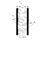
- the second auxiliary groove 5B passes through the third circumferential groove 3C and the fourth circumferential groove 3D, and passes from the fifth land portion 4E on the shoulder inside the vehicle to the fourth land portion 4D at the center via the second land portion 4B. It is provided at the very end. That is, one end of the second auxiliary groove 5B is arranged at the design end D which is the fifth land portion 4E on the shoulder inside the vehicle and inside the vehicle at the ground contact end T, and the other end at the fourth land portion 4D at the center. It is terminated.
- the first auxiliary groove 5A and the second auxiliary groove 5B are formed so that the groove width gradually increases in a direction away from the fourth land portion 4D of the center. Thereby, since drainage improves, the improvement effect of the braking performance on a wet road surface can be assisted.
- the ground contact edge T means both outermost ends in the tire width direction of the ground contact region, and in FIG. 1, the ground contact edge T is shown continuously in the tire circumferential direction.
- the regular rim is “standard rim” defined by JATMA, “Design Rim” defined by TRA, or “Measuring Rim” defined by ETRTO.
- the normal internal pressure is “maximum air pressure” defined by JATMA, the maximum value described in “TIRE LOAD LIMITS AT VARIOUS COLD INFLATION PRESSURES” defined by TRA, or “INFLATION PRESSURES” defined by ETRTO.
- the normal load is “maximum load capacity” defined by JATMA, the maximum value described in “TIRE LOAD LIMITS AT VARIOUS COLD INFLATION PRESSURES” defined by TRA, or “LOAD CAPACITY” defined by ETRTO.
- the design end D is the outermost end in the tire width direction of the tread portion 2 and is the outermost end in the tire width direction in which the auxiliary grooves 5 and the narrow grooves 6 are formed. In FIG. It is shown continuously in the tire circumferential direction.
- first auxiliary groove 5A and the second auxiliary groove 5B are provided to bend in the opposite direction while being inclined in the opposite direction to the tire width direction.
- one of the first auxiliary groove 5A and the second auxiliary groove 5B may be formed along the tire width direction and the other may be provided inclined in the tire width direction.
- the third auxiliary groove 5C is formed in the third land portion 4C with an end portion away from the first circumferential groove 3A on the outermost side of the vehicle. More specifically, the third auxiliary groove 5C is disposed at the design end D, which is the third land portion 4C and outside the vehicle at the ground contact end T, and is separated from the first circumferential groove 3A. The other end terminates in the portion 4C.
- the third auxiliary groove 5C is provided to bend in the opposite direction while being inclined in the same direction with respect to the tire width direction as compared with the second auxiliary groove 5B.
- the third auxiliary groove 5C is formed away from the first circumferential groove 3A, but the decorative groove 7 is interposed between the other end that terminates and the first circumferential groove 3A.
- the decorative groove 7 is formed to have a groove width and a groove depth equal to or smaller than the third auxiliary groove 5 ⁇ / b> C, and is lost due to wear during the initial use of the pneumatic tire 1.
- the effect of improving braking performance on the road surface on snow can be assisted by the edge effect of the third auxiliary groove 5C.
- the rigidity of the third land portion 4C is improved by forming the end portion of the third auxiliary groove 5C away from the first circumferential groove 3A, the effect of improving the braking performance on the dry road surface is achieved. Can help.
- the tread portion 2 has a first block 8A that is partitioned by a first circumferential groove 3A, a second circumferential groove 3B, and a plurality of first auxiliary grooves 5A in the first land portion 4A. Moreover, the tread part 2 has the 2nd block 8B each divided by the 3rd circumferential groove
- the narrow groove 6 includes a first narrow groove 6A, a second narrow groove 6B, a third narrow groove 6C1 and 6C2, a fourth narrow groove 6D, a fifth narrow groove 6E, a sixth narrow groove 6F1 and 6F2, and a seventh narrow groove. Grooves 6G1 and 6G2 and an eighth narrow groove 6H are provided.
- the first narrow groove 6A is provided between the first auxiliary grooves 5A in the tire circumferential direction. One end of the first narrow groove 6A communicates with the first circumferential groove 3A, and the other end communicates with the second circumferential groove 3B.
- the first narrow groove 6A is provided so as to pass through the middle between the plurality of first auxiliary grooves 5A, that is, the central portion of the first block 8A.
- the second narrow groove 6B is formed in the second block 8B so as to be curved to the same side while being inclined in the same direction with respect to the tire width direction as compared with the second auxiliary groove 5B.
- the second narrow groove 6B is arranged as a set of a plurality of (two in this embodiment), one end communicating with the third circumferential groove 3C and the other end communicating with the fourth circumferential groove 3D. Is provided.
- the third narrow grooves 6C1 and 6C2 are provided in the tire circumferential direction of the third auxiliary groove 5C, and are provided in the third land portion 4C.
- the third narrow grooves 6C1 and 6C2 are formed to bend on the same side while being inclined in the same direction with respect to the tire width direction as compared with the third auxiliary groove 5C.
- the third narrow grooves 6C1 and 6C2 are arranged as a set of a plurality (two in the present embodiment), one end portion of which communicates with the first circumferential groove 3A, and the tire width beyond the ground contact end T. Each other end part is connected by the 4th fine groove 6D in the position of the direction outer side.
- the edge effect is improved, and the effect of improving the braking performance on the road surface on snow can be assisted.
- the edge effect can be further improved, and the effect of improving the braking performance on the road surface on snow can be further assisted.
- the edge effect is improved, so that the braking performance on wet road surfaces is improved. Can help.
- the edge effect is further improved, so that the effect of improving the braking performance on the road surface on snow can be assisted.
- At least one fifth narrow groove 6E is provided between the first auxiliary grooves 5A in the fourth land portion 4D.
- the sixth narrow grooves 6F1 and 6F2 are provided between the second auxiliary grooves 5B in the fourth land portion 4D.
- the seventh narrow grooves 6G1 and 6G2 are provided between the second auxiliary grooves 5B in the tire circumferential direction, and are provided in the fifth land portion 4E.
- the seventh narrow grooves 6G1 and 6G2 are formed to bend in the same direction while being inclined in the same direction with respect to the tire width direction as compared with the second auxiliary groove 5B.
- the seventh narrow grooves 6G1 and 6G2 are arranged as a set of a plurality (two in this embodiment), one end portion of which communicates with the fourth circumferential groove 3D, and the tire width is larger than the ground contact end T. Each other end is connected by the eighth narrow groove 6H at a position on the outer side in the direction.
- the sixth fine groove 6F1, the second fine groove 6B, and the seventh fine groove 6G1 may be provided continuously through the third circumferential groove 3C and the fourth circumferential groove 3D, or separately. It may be provided.
- the sixth fine groove 6F2, the second fine groove 6B, and the seventh fine groove 6G2 may be provided continuously through the third circumferential groove 3C and the fourth circumferential groove 3D, or separately. It may be provided.
- a circumferential narrow groove 3S extending in a zigzag shape along the tire circumferential direction is formed on the tread surface 2a of the first land portion 4A.
- the circumferential narrow groove 3S has a zigzag shape in which first bent portions 31 and second bent portions 32 that are bent to the opposite side of the first bent portions 31 are alternately formed.
- the first bent portion 31 and the second bent portion 32 are located near the center of the first block 8A.
- the vicinity of the center of the first block 8A where the first bent portion 31 and the second bent portion 32 are located means a range within 25% from the center of the first block 8A in the tire width direction.
- the first bent portion 31 and the second bent portion 32 are located in a range within 25% of the distance in the tire circumferential direction from the center of the first block 8A to the first auxiliary groove 5A. .
- the circumferential narrow groove 3S In the circumferential narrow groove 3S, a portion between the first bent portion 31 and the second bent portion 32 intersects with the first narrow groove 6A. And in the 1st block 8A, the circumferential direction fine groove 3S has a part between the 1st bending part 31 and the 2nd bending part 32 including the part which cross
- the circumferential narrow groove 3S is, for example, 0.5 mm or more and the other circumferential grooves 3A, 3B, 3C, 3D or less, and the other circumferential grooves 3A, 3B, 3C, 3D or less. The one with groove depth.
- FIG. 2 is a partially enlarged plan view of the pneumatic tire according to the present embodiment, and is an enlarged plan view in the vicinity of the third circumferential groove 3C.
- chamfers 3C1 and 3C2 are provided at the opening edges on both sides in the tire width direction in the third circumferential groove 3C.
- the chamfer 3C1 is provided at the opening edge of the third circumferential groove 3C on the second land portion 4B side, and the chamfer width gradually changes in the tire circumferential direction between the second auxiliary grooves 5B to form a substantially triangular shape.
- the chamfer 3C2 is provided at the opening edge of the third circumferential groove 3C on the fourth land portion 4D side, and the chamfering width gradually changes in the tire circumferential direction between the second auxiliary grooves 5B. Is formed.
- the chamfers 3C1 and 3C2 are arranged by reversing the substantially triangular shape in which the chamfer width gradually changes at the opening edges on both sides of the third circumferential groove 3C.
- the chamfers 3C1 and 3C2 may be formed such that the chamfer width is parallel to the tire circumferential direction.
- FIG. 3 is a partially enlarged plan view of the pneumatic tire according to the present embodiment, and is an enlarged plan view in the vicinity of the fourth land portion 4D.
- the pneumatic tire 1 of the present embodiment has a plurality of first auxiliary grooves 5A that terminate in the fourth land portion 4D and are provided in the tire circumferential direction.
- the second auxiliary groove 5B terminates in the fourth land portion 4D, and a plurality of tires are provided in the tire circumferential direction.
- the first auxiliary grooves 5A and the second auxiliary grooves 5B are alternately arranged without intersecting.
- At least one fifth fine groove 6E is provided between the first auxiliary grooves 5A.
- one fifth narrow groove 6E is provided.
- the sixth fine grooves 6F1 and 6F2 having a larger number than the number of the fifth fine grooves 6E are provided between the second auxiliary grooves 5B.
- two sixth fine grooves 6F1 and 6F2 are provided.
- the longer sixth fine groove 6F1 is the shorter sixth fine groove due to the rotation of the tire during traveling in the forward direction.
- the length of the groove refers to the length of the center line connecting the midpoints of the width of the groove.
- the length a of the longer sixth narrow groove 6F1 is: 0.4 * W2 ⁇ a ⁇ 0.7 * W2 It is preferable that The sixth fine groove 6F1 is preferably shorter than the length of the adjacent second auxiliary groove 5B, and particularly preferably about 50% in length. If the sixth fine groove 6F1 is made longer, the block rigidity is lowered and the braking performance on the dry road surface is lowered.
- the length of the sixth fine groove 6F1 with the longer length is a
- the length of the sixth fine groove 6F2 with the shorter length is Where b is 0.7a ⁇ b ⁇ 0.9a It is preferable that in particular, it is preferable that the adjacent two sixth fine grooves 6F1 and 6F2 be approximately 80% of the shorter sixth fine groove 6F2 of the longer sixth fine groove 6F1.
- the shape of the fifth fine groove 6E and the sixth fine grooves 6F1 and 6F2 may be a linear shape or a curved shape.
- the shapes of the fifth fine groove 6E and the sixth fine grooves 6F1 and 6F2 are preferably formed as arcs. By using an arc, the support of the block can be produced and the braking performance on the road surface on snow can be improved.
- 4A and 4B are diagrams illustrating the relationship between the direction of the shape of the fifth fine groove 6E and the direction of the shape of the sixth fine grooves 6F1 and 6F2.
- the curved shape of the fifth fine groove 6E and the curved shape of the sixth fine grooves 6F1 and 6F2 are formed in opposite directions so as to face each other. That is, the fifth fine groove 6E and the sixth fine groove 6F1 are arranged such that one convex direction of the curved shape faces the tire rotating direction and the concave direction of the other curved shape faces the tire rotating direction. Similarly, the fifth fine groove 6E and the sixth fine groove 6F2 are also arranged so that one curved convex direction faces the tire rotating direction and the other curved concave direction faces the tire rotating direction. .
- the fifth fine groove 6E and the sixth fine groove 6F1 have a relationship in which the distances L1 and L2 in the tire circumferential direction at both ends in the tire width direction are shorter than the distance L3 in the tire circumferential direction at the center in the tire width direction. It is arranged.
- the fifth fine groove 6E and the sixth fine groove 6F1 are both arranged so that the concave direction of the curved shape faces the tire rotation direction.
- the distance L2 in the tire circumferential direction at one end in the tire width direction is shorter than the distance L3 in the tire circumferential direction at the center in the tire width direction.
- the distance L1 in the tire circumferential direction at the other end in the tire width direction is arranged so as to be longer than the distance L3 in the tire circumferential direction at the center in the tire width direction.
- the concave shape of the curved shape of the fifth fine groove 6E and the sixth fine groove 6F1 is directed in the same direction as in FIG. 4B, and the convex direction of one curved shape as in FIG. 4A. It is preferably arranged in the opposite direction so that the direction of rotation is the tire rotation direction and the concave direction of the other curved shape is the rotation direction of the tire. The same applies to the relationship between the fifth fine groove 6E and the sixth fine groove 6F2.
- one of the curved convex directions is directed to the tire rotation direction, and the other is the curved concave direction is the tire.
- the narrow grooves support each other, and the braking performance on the dry road surface can be improved without deteriorating the braking performance on the road surface on snow.
- the rigidity can be changed between the vehicle inner side and the vehicle outer side with respect to the tire equatorial plane CL, and the braking performance on the dry road surface, particularly the performance at the time of turning can be improved.
- first auxiliary groove 5A is disposed outside the vehicle and the second auxiliary groove 5B is disposed inside the vehicle.
- the rigidity on the outside of the vehicle can be increased, and the braking performance on the dry road surface, particularly the performance during turning can be improved.
- FIG. 5 is a diagram schematically showing the configuration of FIG. Referring to FIG. 5, a circumferential narrow groove 3S is provided between the first circumferential groove 3A and the second circumferential groove 3B.
- the first auxiliary groove 5A is provided so as to communicate the first circumferential groove 3A and the second circumferential groove 3B.
- the first narrow groove 6A is provided between the first auxiliary grooves 5A. The first narrow groove 6A passes through the circumferential narrow groove 3S.
- the second auxiliary groove 5B is provided so as to communicate the third circumferential groove 3C and the fourth circumferential groove 3D.
- the second narrow groove 6B is provided between the second auxiliary grooves 5B. According to such a configuration, it is possible to stabilize the braking performance during straight traveling and cornering on the road surface on snow.
- FIG. 6 is a diagram schematically showing a modified example having one circumferential groove.
- the pneumatic tire of this example has a circumferential narrow groove 3BC instead of the second circumferential groove 3B and the third circumferential groove 3C.
- the number of circumferential grooves other than the circumferential narrow grooves 3S is only one circumferential narrow groove 3BC.
- the first narrow groove 6A is provided between the first auxiliary grooves 5A and penetrates the circumferential narrow groove 3S.
- the second narrow groove 6B is provided between the second auxiliary grooves 5B. According to such a configuration, it is possible to stabilize the braking performance during straight traveling and cornering on the road surface on snow.
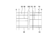
- FIG. 7 is a diagram schematically showing a modified example having three circumferential grooves.
- the pneumatic tire of this example has a circumferential narrow groove 3BC instead of the second circumferential groove 3B and the third circumferential groove 3C.
- the first circumferential groove 6A is provided between the first auxiliary grooves 5A and penetrates the circumferential narrow groove 3S.
- the second narrow groove 6B is provided between the second auxiliary grooves 5B. According to such a configuration, it is possible to stabilize the braking performance during straight traveling and cornering on the road surface on snow.
- the pneumatic tire 1 of the present embodiment has the asymmetric tread portion 2 with respect to the tire equatorial plane CL, and the tread portion 2 is formed on the outer side in the tire width direction with respect to the tire equatorial plane CL.
- the first land portion 4A and the second land portion 4B formed inside the tire width direction on the basis of the tire equatorial plane CL.
- the first land portion 4A includes a circumferential narrow groove 3S extending in the circumferential direction.
- a first narrow groove 6A that penetrates the groove 3S is formed, and the second land portion 4B is partitioned by a plurality of second auxiliary grooves 5B and a plurality of second auxiliary grooves 5B that are periodically provided in the circumferential direction.
- the braking performance at the time of straight traveling on the snow road surface and cornering can be stabilized, and the wet road surface can be stabilized.
- the effect of improving the braking performance can be assisted.
- the circumferential narrow groove 3S has a zigzag shape in which the first bent portion 31 and the second bent portion 32 that is bent on the opposite side of the first bent portion 31 are alternately formed.
- the first bent portion 31 and the second bent portion 32 are located near the center of the first block 8A.
- the edge effect can be improved by the zigzag-shaped circumferential narrow groove 3 ⁇ / b> S having more edges than the straight, and the effect of improving the braking performance on the snowy road surface can be assisted. Further, since the zigzag bent portion is located near the center of the land portion, the rigidity of the block can be maintained as compared with the case where the bent portion is located at the end of the land portion.
- the circumferential narrow groove 3S includes a first narrow groove 6A at a portion between the first bent portion 31 and the second bent portion 32 in one first block 8A.
- the part between the first bent part 31 and the second bent part 32 including the part that intersects the first narrow groove 6A is shorter than the other parts.
- the zigzag portion is located in the center of the block, and the narrow groove penetrates the block, so that the block can be divided almost equally into four, and the rigidity from either the front or rear and lateral directions Therefore, the braking performance on the dry road surface can be maintained.
- the tread portion 2 includes the first circumferential groove 3A provided on the outer side in the tire width direction of the first land portion 4A and the outer side in the tire width direction of the first circumferential groove 3A.
- the third land portion 4C further includes a non-through third auxiliary groove 5C in the first circumferential groove 3A.
- this pneumatic tire 1 it is possible to assist the effect of improving the braking performance on the road surface on snow by having a non-penetrating auxiliary groove in the circumferential groove in the outer land portion, and to block by making a rib shape
- the braking performance on the dry road surface can be improved by increasing the rigidity.
- a plurality of the third auxiliary grooves 5C are formed in the tire circumferential direction, and at least two third land portions 4C are provided between the third auxiliary grooves 5C.
- a fourth fine groove 6D that is connected and extends in the circumferential direction is formed.
- this pneumatic tire 1 by arranging at least two narrow grooves, an edge effect can be brought out in the land, and the drainage can be enhanced as well as the braking performance on the road surface on snow.
- the tread portion 2 is formed at the outer end in the tire width direction of the first land portion 4A, and the first circumferential groove 3A that partitions the first land portion 4A; Formed at the end of the first land portion 4A on the inner side in the tire width direction, formed at the second circumferential groove 3B that partitions the first land portion 4A, and at the end of the second land portion 4B on the inner side in the tire width direction, A third circumferential groove 3C that divides the second land portion 4B, and a fourth circumferential groove 3D that is formed at the outer end in the tire width direction of the second land portion 4B and divides the second land portion 4B.
- the first land portion 4A is partitioned by a first circumferential groove 3A and a second circumferential groove 3B provided from the first circumferential groove 3A to the tire equatorial plane CL.
- the third circumferential groove 3C provided from the tire equatorial plane CL of the second land portion 4B and the outer side in the tire width direction of the second land portion 4B
- a fourth land portion 4D that is defined by the fourth circumferential groove 3D and that is defined by the second circumferential groove 3B and the third circumferential groove 3C and that is positioned on the tire equatorial plane CL.
- the first auxiliary groove 5A extends through the second land portion 4D through the second circumferential groove 3B and terminates at the fourth land portion 4D.
- the second auxiliary groove 5B It extends through 3C to the fourth land portion 4D and terminates at the fourth land portion 4D.
- This pneumatic tire 1 has four circumferential grooves and forms a land portion on the tire equatorial plane CL.
- the land portion of the center portion of the tread surface is not made into a block shape but is made into a rib, thereby improving the braking performance on the dry road surface.
- the third circumferential groove 3C is provided with chamfers 3C1 and 3C2 at the opening edges on both sides in the tire width direction.
- the chamfers 3C1 and 3C2 are formed such that the chamfer width gradually changes in the tire circumferential direction between the second auxiliary grooves 5B, and the third circumference The direction grooves 3C are reversed and arranged at the opening edges on both sides.
- the chamfering is reversed and formed alternately at the opening edges on both sides of the third circumferential groove, so that the snow drainage is improved, so that the braking performance on the road surface on snow is improved.
- the improvement effect can be supported.
- the fourth land portion 4D has a position where the first auxiliary groove 5A penetrating the second circumferential groove 3B ends and a second portion penetrating the third circumferential groove 3C.
- the positions where the auxiliary grooves 5B end are alternately arranged in the tire circumferential direction.
- the pneumatic tire 1 it is possible to achieve both wear resistance performance on a dry road surface and braking performance on a wet road surface and a snowy road surface.
- the fourth land portion 4D is partitioned by the second circumferential groove 3B and the third circumferential groove 3C, and the first auxiliary groove 5A is formed in the fourth land portion 4D.
- a plurality of second auxiliary grooves 5B that terminate in the tire circumferential direction and end in the fourth land portion 4D and that are provided in the tire circumferential direction are provided, the first auxiliary groove 5A and the second auxiliary groove 5B.
- Six auxiliary grooves 6F1 and 6F2 provided more than 6E are further included.
- the pneumatic tire 1 it is possible to achieve both wear resistance performance on a dry road surface and braking performance on a wet road surface and a snowy road surface.
- the sixth fine grooves 6F1 and 6F2 have different lengths depending on the positions between the second auxiliary grooves 5B, and the longer grooves when traveling in the forward direction. However, it should be grounded before the shorter groove.
- the pneumatic tire 1 can maintain braking performance on a dry road surface and improve braking performance on a snowy road surface.
- the fourth land portion 4D has the length of the formed sixth auxiliary groove 6F1 with the longer length when the length of the formed second auxiliary groove 5B is W2.
- Length a is 0.4 * W2 ⁇ a ⁇ 0.7 * W2 It is.
- the block rigidity can be maintained and the braking performance on the dry road surface can be maintained.
- the length of the sixth fine groove 6F1 having the longer length among the at least two sixth fine grooves 6F1 and 6F2 having different lengths is indicated by a.
- the length of the shorter sixth narrow groove 6F2 is b, 0.7a ⁇ b ⁇ 0.9a It is.
- the block rigidity can be maintained and the braking performance on the dry road surface can be maintained.
- the sixth fine grooves 6F1 and 6F2 have a curved shape.
- the support of the block can be produced and the braking performance on the road surface on snow can be improved.
- the shape of the fifth fine groove 6E is a curved shape
- the curved shape of the fifth fine groove 6E and the curved shape of the sixth fine grooves 6F1, 6F2 are one of the curved shapes. It is arranged so that the convex direction of the curved shape faces the tire rotating direction and the concave direction of the other curved shape faces the tire rotating direction, and the distance in the tire circumferential direction at both ends in the tire width direction is the center in the tire width direction. It is shorter than the distance in the tire circumferential direction.
- the narrow grooves support each other, and the braking performance on the dry road surface can be improved without deteriorating the braking performance on the road surface on snow.
- the fourth land portion 4D has the length of the formed first auxiliary groove 5A as W1, and the length of the formed second auxiliary groove 5B as W2. In case, W1 ⁇ W2 It is.
- the rigidity can be changed between the vehicle inner side and the vehicle outer side with respect to the tire equatorial plane CL, and the braking performance on the dry road surface, particularly the performance during turning can be improved.
- the first auxiliary groove 5A is disposed on the vehicle outer side when the vehicle is mounted, and the second auxiliary groove 5B is disposed on the vehicle inner side when the vehicle is mounted.
- the braking performance on a dry road surface, particularly the performance during turning can be improved by increasing the rigidity on the outside of the vehicle.
- the first auxiliary groove 5A and the second auxiliary groove 5B are arranged in the fourth land portion 4D.
- the first auxiliary groove and the second auxiliary groove are arranged in the center of the tread surface, and both improvement in wear resistance performance on a dry road surface and improvement in braking performance on a wet road surface and on a snowy road surface are achieved. can do.
- the pneumatic tire 1 of the present embodiment further includes a fifth land portion 4E provided on the vehicle inner side when the fourth circumferential groove 3D is mounted on the vehicle, and the second auxiliary groove 5B includes the fifth land portion. It passes through 4E and the fourth circumferential groove 3D.
- the rigidity on the outside of the vehicle can be increased, and the braking performance on a dry road surface, particularly the performance during turning can be improved.
- a plurality of the second auxiliary grooves 5B are provided in the tire circumferential direction, and at least two seventh narrow grooves 6G1, between the second auxiliary grooves 5B, 6G2 is provided, and at least two of the seventh narrow grooves 6G1 and 6G2 are connected to each other by an eighth narrow groove 6H whose one end communicates with the fourth circumferential groove 3D and whose other end extends in the circumferential direction. linked.
- this pneumatic tire 1 by arranging at least two narrow grooves, an edge effect can be brought out in the land, and the drainage can be enhanced as well as the braking performance on the road surface on snow.
- the first fine groove 6A, the second fine groove 6B, the third fine grooves 6C1 and 6C2, the fourth fine groove 6D, the seventh fine grooves 6G1 and 6G2, and the eighth fine groove 6H, the 5th fine groove 6E, and the 6th fine groove 6F1 and 6F2 are formed in the range whose groove width is 0.4 mm or more and 1.2 mm or less.
- each narrow groove is configured as a so-called sipe, the edge effect is improved and the effect of improving the braking performance on the road surface on snow can be assisted.
- performance tests on a braking performance on a wet road surface, a braking performance on a snowy road surface, and a braking performance on a dry road surface were performed on a plurality of types of test tires having different conditions.
- the method for evaluating the braking performance on wet roads is to measure the braking distance from a speed of 100 km / h on a test course on a wet road with a water depth of 1 mm using the test vehicle. Based on this measurement result, index evaluation is performed with the conventional example 1 as a reference (100). This evaluation is preferable as the numerical value increases.
- the evaluation method of the braking performance on the road surface on snow measures the braking distance in ABS (Anti-lock Braking System) braking from 40 km / h on the test course of the snow compression road surface with the above test vehicle. Based on this measurement result, index evaluation is performed with the conventional example 1 as a reference (100). This evaluation is preferable as the numerical value increases.
- ABS Anti-lock Braking System
- the evaluation method of the turning performance on the snowy road surface is carried out by running the test course on the snowy road surface at a speed of 40 [km / h] with the above-mentioned test vehicle, and the sensory evaluation by the test driver for the turning stability during cornering.
- This sensory evaluation is index evaluation based on the pneumatic tire of Conventional Example 1 (100). This evaluation shows that the larger the value, the better the turning performance on the road surface on snow.
- the evaluation method of the braking performance on the dry road surface is that the braking distance from 100 km / h is measured on the dry road surface test course with the test vehicle. Based on this measurement result, index evaluation is performed with the conventional example 1 as a reference (100). This evaluation is preferable as the numerical value increases.
- the auxiliary groove (first auxiliary groove 5A) on the vehicle outer side when the vehicle is mounted communicates with the first circumferential groove 3A and the second circumferential groove 3B
- An auxiliary groove (second auxiliary groove 5B) on the vehicle inner side when the vehicle is mounted communicates with the third circumferential groove 3C and the fourth circumferential groove 3D.
- the pneumatic tire of Conventional Example 1 has one narrow groove 6A and 6B on the vehicle inner side and the vehicle outer side when the vehicle is mounted.
- the pneumatic tire of Conventional Example 1 does not have the circumferential narrow groove 3S communicating in the circumferential direction, and the third auxiliary groove 5C of the third land portion 4C penetrates the first circumferential groove 3A.
- the number of grooves is four.
- the first auxiliary groove 5A and the second auxiliary groove 5B penetrate the main groove in the fourth land portion 4D, and the second auxiliary groove 5B becomes the main groove in the fifth land portion 4E. It is a penetrating shape.
- the pneumatic tire of Conventional Example 1 has a shape in which the number of narrow grooves in the third land portion 4C is one and penetrates the first circumferential groove 3A, and the number of narrow grooves in the fifth land portion 4E. Is a shape penetrating through the fourth circumferential groove 3D.
- the pneumatic tire of Conventional Example 1 has a shape in which the width of each narrow groove is 0.8 mm and the third circumferential groove 3C is chamfered.
- the pneumatic tire of Conventional Example 1 has a shape in which one fifth fine groove 6E and one sixth fine groove are formed in the fourth land portion 4D.
- the auxiliary grooves (first auxiliary grooves 5A) on the vehicle outer side when the vehicle is mounted are the first circumferential grooves 3A and the second circumferential grooves 3B.
- an auxiliary groove (second auxiliary groove 5B) on the vehicle inner side when the vehicle is mounted communicates with the third circumferential groove 3C and the fourth circumferential groove 3D.
- the pneumatic tires of Examples 1 to 12 have one narrow groove (first narrow groove 6A) on the vehicle outer side when the vehicle is mounted, and one narrow groove (second narrow groove on the vehicle inner side when the vehicle is mounted). There are two grooves 6B).
- the shape of the circumferential narrow groove 3S communicating in the circumferential direction is straight, and the pneumatic tires of Examples 3 to 12 are circumferentially narrow communicating in the circumferential direction.
- the shape of the groove 3S is zigzag.
- the pneumatic tires of Examples 1 to 3 have a shape in which the third auxiliary groove 5C of the third land portion 4C penetrates the first circumferential groove 3A, and the pneumatic tires of Examples 4 to 12
- the tire has a shape in which the auxiliary groove of the third land portion 4C does not penetrate through the first circumferential groove 3A (non-penetrating).
- the pneumatic tire of Example 1 has one circumferential groove (main groove), and the pneumatic tires of Examples 2 to 4 have three circumferential grooves (main grooves). In the pneumatic tires of Examples 5 to 12, the number of circumferential grooves (main grooves) is four.
- the pneumatic tires of Examples 1 to 4 have a shape in which the first auxiliary groove 5A and the second auxiliary groove 5B formed in the fourth land portion 4D pass through the main groove.
- Examples 5 to 12 This pneumatic tire has a shape in which the first auxiliary groove 5A and the second auxiliary groove 5B formed in the fourth land portion 4D do not penetrate the main groove.
- the pneumatic tires of Examples 1 to 5 have a shape in which the second auxiliary groove 5B does not penetrate the main groove in the fifth land portion 4E, and the pneumatic tires of Examples 6 to 12 are the fifth land. In the portion 4E, the second auxiliary groove 5B penetrates the main groove.
- the pneumatic tires of Examples 1 to 7 have a shape in which the number of narrow grooves in the third land portion 4C is one and does not penetrate the first circumferential groove 3A.
- the pneumatic tire has a shape in which the number of narrow grooves in the third land portion 4C is two and penetrates through the first circumferential groove 3A.
- the pneumatic tires of Examples 1 to 8 have a shape in which the number of narrow grooves in the fifth land portion 4E is one and does not penetrate the fourth circumferential groove 3D.
- the pneumatic tire has a shape in which the number of narrow grooves in the fifth land portion 4E is two and penetrates through the fourth circumferential groove 3D.
- each fine groove is 1.3 mm
- the width of each fine groove is 0.6 mm.
- the pneumatic tires of Examples 1 to 10 have a shape without chamfering of the third circumferential groove 3C, and the pneumatic tires of Examples 11 and 12 have chamfering of the third circumferential groove 3C. Shape.
- the pneumatic tires of Examples 1 to 11 have a shape in which the fourth land portion 4D has no fifth fine groove and one sixth fine groove is formed.
- the pneumatic tire of Example 12 has the shape In the four-land portion 4D, one fifth fine groove and two sixth fine grooves are formed.
- the first auxiliary groove 5A and the second auxiliary groove 5B do not communicate with the circumferential groove (main groove). There are one narrow groove and two narrow grooves inside the vehicle when the vehicle is mounted.
- the shape of the circumferential narrow groove 3S communicating in the circumferential direction is straight, and the auxiliary groove of the third land portion 4C does not penetrate through the first circumferential groove 3A (non-penetrating). It is.
- the pneumatic tire of Comparative Example 1 has four circumferential grooves (main grooves), and the first auxiliary groove 5A and the second auxiliary groove 5B do not penetrate the main groove in the fourth land portion 4D.
- the pneumatic tire of Comparative Example 1 has a shape in which only one (only one side) of the first auxiliary groove 5A and the second auxiliary groove 5B is formed in the fourth land portion 4D.
- the pneumatic tire of Comparative Example 1 has a shape in which the number of narrow grooves in the third land portion 4C is two and does not penetrate the first circumferential groove 3A.
- the pneumatic tire of Comparative Example 1 has a shape in which the number of narrow grooves in the fifth land portion 4E is two and does not penetrate the fourth circumferential groove 3D.
- the pneumatic tire of Comparative Example 1 has a shape in which the width of each narrow groove is 0.6 mm and the third circumferential groove 3C is not chamfered. Further, the pneumatic tire of Comparative Example 1 has a shape in which the fifth fine groove 6E and the sixth fine groove are not provided in the fourth land portion 4D.
- the pneumatic tires of Examples 1 to 12 have braking performance on wet road surfaces (“wet performance (braking performance)” in Table 1), braking performance on snowy road surfaces ( “Snow performance (braking performance)” in Table 1), turning performance on snowy road surface (“Snow performance (turning performance)” in Table 1), braking performance on dry road surface (“Dry performance (braking performance)” in Table 1 ", It can be seen that there is an improvement.
- Table 2 shows the results of performance tests on a plurality of types of test tires based on Example 11 shown in Table 1.
- the evaluation method of the braking performance on the wet road surface, the snowy road surface and the dry road surface is the same as in Table 1.
- the evaluation method of the turning performance on the dry road surface is that the test vehicle runs on a flat and dry test course at a speed of 60 [km / h] to 100 [km / h], and the turning stability during cornering is as follows. Perform by sensory evaluation with a test driver. This sensory evaluation is index evaluation based on the pneumatic tire of Example 11 (100). This evaluation shows that the larger the value, the better the turning performance on the dry road surface.
- the evaluation method of uneven wear resistance performance on dry road surface is the uneven wear (side rib-shaped land) generated in the rib-shaped land portion after running 50,000 [km] at an average speed of 60 [km / h] on the test vehicle.
- the difference in the amount of wear on the tread surface between the part and the other rib-like land part) is measured. Then, based on this measurement result, index evaluation using Example 11 as a reference (100) is performed. This evaluation indicates that the larger the value, the better the uneven wear resistance performance.
- the number of circumferential grooves is four, and the first auxiliary grooves 5A and the second auxiliary grooves 5B formed in the fourth land portion 4D are circumferential.
- the shape does not penetrate through the groove (non-penetrating).
- the pneumatic tire of Example 11 has a shape in which the first auxiliary grooves 5A and the second auxiliary grooves 5B are alternately arranged in the fourth land portion 4D.
- the pneumatic tire of Example 11 has no narrow groove on the first auxiliary groove 5A side, and the number of narrow grooves on the second auxiliary groove 5B side is one. In the pneumatic tire of Example 11, the length of the narrow groove on the second auxiliary groove 5B side is the same.
- the length a of the narrow groove 6F1 on the second auxiliary groove 5B side is the same as the length W2 of the second auxiliary groove 5B, and the length of the narrow groove 6F2 on the second auxiliary groove 5B side.
- the length b is the same as the length a of the narrow groove 6F1.
- the shape of the narrow grooves 6E, 6F1, and 6F2 is a straight line.
- the arrangement of the narrow grooves 6E with respect to the narrow grooves 6F1 and 6F2 is the same direction.
- the length W1 of the first auxiliary groove 5A is the same as the length W2 of the second auxiliary groove 5B.
- each narrow groove has a width of 0.6 mm.
- Table 2 the pneumatic tires of Examples 13 to 28 are evaluated based on the pneumatic tire of Example 11.
- the number of circumferential grooves (main grooves) is two and the first auxiliary grooves 5A and the second auxiliary grooves 5B are not communicated with the circumferential grooves.
- the number of circumferential grooves (main grooves) is four, and the first auxiliary grooves 5A and the second auxiliary grooves 5B are circumferential grooves. It is a shape that communicates.
- the pneumatic tires of Examples 13 to 28 have a shape in which the first auxiliary grooves 5A and the second auxiliary grooves 5B are alternately arranged.
- the number of narrow grooves on the first auxiliary groove 5A side is one and the number of narrow grooves on the second auxiliary groove 5B side is two.
- the pneumatic tire of Example 13 has the same length of the narrow groove on the second auxiliary groove 5B side, and the pneumatic tires of Examples 14 to 28 have the length of the narrow groove on the second auxiliary groove 5B side.
- the shapes are different in length (change in length).
- the length a of the narrow groove 6F1 on the second auxiliary groove 5B side is the same as the length W2 of the second auxiliary groove 5B.
- the length a of the narrow groove 6F1 on the second auxiliary groove 5B side is 30% (0.3 * W2), 50% (0.5 * W2) of the length W2 of the second auxiliary groove 5B, They are 40% (0.4 * W2), 70% (0.7 * W2), and 80% (0.8 * W2).
- the length b of the narrow groove 6F2 on the second auxiliary groove 5B side is the same as the length a of the narrow groove 6F1, and the pneumatic tires of Examples 20 to 28 are used.
- the length b of the narrow groove 6F2 on the second auxiliary groove 5B side is 60% (0.6 * a), 70% (0.7 * a), and 80% (0) of the length a of the narrow groove 6F1. 8 * a) and 90% (0.9 * a).
- the shapes of the narrow grooves 6E, 6F1, and 6F2 are linear, and in the pneumatic tires of Examples 24 to 28, the shapes of the narrow grooves 6E, 6F1, and 6F2 are formed. It is a curve.
- the arrangement of the narrow grooves 6E with respect to the narrow grooves 6F1 and 6F2 is the same direction, and the pneumatic tires of Examples 25 to 28 are thin with respect to the narrow grooves 6F1 and 6F2.
- the arrangement of the grooves 6E is opposite.
- the length W1 of the first auxiliary groove 5A is the same as the length W2 of the second auxiliary groove 5B, and the pneumatic tires of Examples 26 to 28 are the same.
- the relationship between the length W1 of the first auxiliary groove 5A and the length W2 of the second auxiliary groove 5B is W1 ⁇ W2.
- the position of the first auxiliary groove 5A is inside the vehicle and the position of the second auxiliary groove 5B is outside the vehicle.
- the pneumatic tires of Examples 27 and 28 are the first The position of the auxiliary groove 5A is the vehicle outer side, and the position of the second auxiliary groove 5B is the vehicle inner side.
- each fine groove is 1.3 mm
- the width of each fine groove is 0.6 mm.
- the pneumatic tires of Examples 13 to 28 have braking performance on wet road surfaces (“wet performance (braking performance)” in Table 2) and braking performance on snowy road surfaces ( It can be seen that “snow performance (braking performance)” in Table 2 and braking performance on dry road surfaces (“dry performance (braking performance)” in Table 2) are improved. Further, the turning performance on the dry road surface (“Dry performance (turning performance)” in Table 2) and the wear resistance performance on the dry road surface (“Dry road surface wear resistance performance” in Table 2) are improved. I understand.
- the first auxiliary grooves 5A and the second auxiliary grooves 5B are alternately arranged in the fourth land portion 4D, and the number of narrow grooves on the first auxiliary groove 5A side is 1.
- the number of narrow grooves on the second auxiliary groove 5B side is two, the length, shape, and arrangement of the narrow grooves, as well as the length of the first auxiliary groove 5A, as in Examples 13 to 28, and The braking performance can be improved by changing the arrangement.
Abstract
Description
0.4*W2≦a≦0.7*W2
であることが好ましい。第六細溝6F1は、隣り合う第二補助溝5Bの長さより短くすることが好ましく、特に約50%の長さとすることが好ましい。第六細溝6F1をそれ以上長くすると、ブロック剛性が下がり、乾燥路面での制動性能が低下する。 Here, when the length of the second
0.4 * W2 ≦ a ≦ 0.7 * W2
It is preferable that The sixth fine groove 6F1 is preferably shorter than the length of the adjacent second
0.7a≦b≦0.9a
であることが好ましい。特に、隣り合う2本の第六細溝6F1、6F2同士については、短い方の第六細溝6F2の長さが長い方の第六細溝6F1の約80%とすることが好ましい。 Of the at least two sixth fine grooves 6F1 and 6F2 having different lengths, the length of the sixth fine groove 6F1 with the longer length is a, and the length of the sixth fine groove 6F2 with the shorter length is Where b is
0.7a ≦ b ≦ 0.9a
It is preferable that In particular, it is preferable that the adjacent two sixth fine grooves 6F1 and 6F2 be approximately 80% of the shorter sixth fine groove 6F2 of the longer sixth fine groove 6F1.
W1≦W2
であることが好ましい。こうすることにより、タイヤ赤道面CLに対して車両内側と車両外側とで剛性を変えることができ、乾燥路面での制動性能、特に旋回時の性能を向上させることができる。 Returning to FIG. 3, when the length of the first
W1 ≦ W2
It is preferable that By doing so, the rigidity can be changed between the vehicle inner side and the vehicle outer side with respect to the tire equatorial plane CL, and the braking performance on the dry road surface, particularly the performance at the time of turning can be improved.
0.4*W2≦a≦0.7*W2
である。 Moreover, in the
0.4 * W2 ≦ a ≦ 0.7 * W2
It is.
0.7a≦b≦0.9a
である。 Moreover, in the
0.7a ≦ b ≦ 0.9a
It is.
W1≦W2
である。 Moreover, in the
W1 ≦ W2
It is.


2 トレッド部
2a トレッド面
3 周方向溝
3A 第一周方向溝
3B 第二周方向溝
3BC 周方向細溝
3C 第三周方向溝
3C1,3C2 面取
3D 第四周方向溝
3S 周方向細溝
4 陸部
4A 第一陸部
4B 第二陸部
4C 第三陸部
4D 第四陸部
4E 第五陸部
5 補助溝
5A 第一補助溝
5B 第二補助溝
5C 第三補助溝
6 細溝
6A 第一細溝
6B 第二細溝
6C1、6C2 第三細溝
6D 第四細溝
6E 第五細溝
6F1、6F2 第六細溝
6G1、6G2 第七細溝
6H 第八細溝
7 飾溝
8A 第一ブロック
8B 第二ブロック
31 第一折れ曲がり部
32 第二折れ曲がり部
CL タイヤ赤道面
D デザインエンド
T 接地端 DESCRIPTION OF
Claims (24)
- タイヤ赤道面を基準として非対称のトレッド部を有し、
前記トレッド部は、前記タイヤ赤道面を基準として車両装着時での車両外側に形成された第一陸部と、前記タイヤ赤道面を基準として車両装着時での車両内側に形成された第二陸部とを含み、
前記第一陸部は、
周方向に延びる周方向細溝と、周方向に周期的に設けられて前記周方向細溝を貫通する複数の第一補助溝と、前記複数の第一補助溝によってそれぞれ区画された第一ブロックに設けられて前記周方向細溝を貫通する第一細溝と、が形成され、
前記第二陸部は、
周方向に周期的に設けられた複数の第二補助溝と、前記複数の第二補助溝によってそれぞれ区画された第二ブロックに設けられた第二細溝とが形成され、
前記第二細溝は、1つの区画あたりの本数が前記第一細溝の本数よりも多い空気入りタイヤ。 It has an asymmetric tread with respect to the tire equator,
The tread portion includes a first land portion formed on the vehicle outer side when the vehicle is mounted with respect to the tire equator plane, and a second land formed on the vehicle inner side with the tire equator surface as a reference. Including
The first land portion is
A circumferential narrow groove extending in the circumferential direction, a plurality of first auxiliary grooves periodically provided in the circumferential direction and penetrating the circumferential narrow groove, and a first block defined by the plurality of first auxiliary grooves, respectively. A first narrow groove that is provided through and penetrates the circumferential narrow groove,
The second land portion is
A plurality of second auxiliary grooves provided periodically in the circumferential direction and second fine grooves provided in second blocks respectively partitioned by the plurality of second auxiliary grooves are formed.
The second fine groove is a pneumatic tire in which the number of one per section is larger than the number of the first fine grooves. - 前記周方向細溝は、
第一折れ曲がり部と前記第一折れ曲がり部とは反対側に折れ曲がる第二折れ曲がり部とが交互に形成されたジグザグ形状であり、
前記第一折れ曲がり部および前記第二折れ曲がり部が前記第一ブロックの中央付近に位置している
請求項1に記載の空気入りタイヤ。 The circumferential narrow groove is
A zigzag shape in which a first bent portion and a second bent portion that is bent on the opposite side of the first bent portion are alternately formed,
The pneumatic tire according to claim 1, wherein the first bent portion and the second bent portion are located near the center of the first block. - 前記周方向細溝は、
1つの前記第一ブロックにおいて、前記第一折れ曲がり部と前記第二折れ曲がり部との間の部分が前記第一細溝と交わり、かつ、前記第一細溝と交わる部分を含む前記第一折れ曲がり部と前記第二折れ曲がり部との間の部分がそれ以外の部分より短い
請求項1または2に記載の空気入りタイヤ。 The circumferential narrow groove is
In one of the first blocks, the first bent portion including a portion where the portion between the first bent portion and the second bent portion intersects with the first fine groove and intersects with the first fine groove. The pneumatic tire according to claim 1 or 2, wherein a portion between the first bent portion and the second bent portion is shorter than the other portions. - 前記トレッド部は、前記第一陸部のタイヤ幅方向外側に設けられた第一周方向溝と、前記第一周方向溝のタイヤ幅方向外側に設けられた第三陸部とをさらに含み、
前記第三陸部は、前記第一周方向溝に非貫通の第三補助溝が形成されている
請求項1から請求項3のいずれか1項に記載の空気入りタイヤ。 The tread portion further includes a first circumferential groove provided on the outer side in the tire width direction of the first land portion, and a third land portion provided on the outer side in the tire width direction of the first circumferential groove,
The pneumatic tire according to any one of claims 1 to 3, wherein the third land portion is formed with a non-penetrating third auxiliary groove in the first circumferential groove. - 前記第一細溝および前記第二細溝は、溝幅が0.4mm以上1.2mm以下である
請求項1から請求項4のいずれか1項に記載の空気入りタイヤ。 The pneumatic tire according to any one of claims 1 to 4, wherein the first narrow groove and the second narrow groove have a groove width of 0.4 mm or more and 1.2 mm or less. - 前記第三補助溝は、タイヤ周方向に複数形成されており、
前記第三陸部は、前記第三補助溝同士の間に少なくとも2本設けられ、一端が前記第一周方向溝に連通する第三細溝と、前記第三補助溝同士の間に設けられた前記少なくとも2本の第三細溝の他端のそれぞれに接続され、周方向に延びる第四細溝と、が形成されている
請求項4または5に記載の空気入りタイヤ。 A plurality of the third auxiliary grooves are formed in the tire circumferential direction,
At least two of the third land portions are provided between the third auxiliary grooves, and one end is provided between the third auxiliary groove and the third narrow groove communicating with the first circumferential groove. The pneumatic tire according to claim 4 or 5, wherein a fourth fine groove connected to each of the other ends of the at least two third fine grooves and extending in the circumferential direction is formed. - 前記第三細溝および前記第四細溝は、溝幅が0.4mm以上1.2mm以下である
請求項6に記載の空気入りタイヤ。 The pneumatic tire according to claim 6, wherein the third narrow groove and the fourth narrow groove have a groove width of 0.4 mm or more and 1.2 mm or less. - 前記トレッド部は、
前記第一陸部のタイヤ幅方向外側の端部に形成され、前記第一陸部を区画する第一周方向溝と、前記第一陸部のタイヤ幅方向内側の端部に形成され、前記第一陸部を区画する第二周方向溝と、前記第二陸部の車両装着時での車両外側の端部に形成され、前記第二陸部を区画する第三周方向溝と、前記第二陸部の車両装着時での車両内側の端部に形成され、前記第二陸部を区画する第四周方向溝とを含み、
前記第一陸部は、前記第一周方向溝と、該第一周方向溝よりタイヤ赤道面よりに設けられた第二周方向溝とによって区画され、
前記第二陸部は、該第二陸部のタイヤ赤道面よりに設けられた第三周方向溝と該第二陸部の車両装着時での車両内側に設けられた第四周方向溝とによって区画され、
前記第二周方向溝と前記第三周方向溝とによって区画され、かつ、前記タイヤ赤道面上に位置する第四陸部をさらに含み、
前記第一補助溝は、前記第二周方向溝を貫通して前記第四陸部に延在して該第四陸部で終端し、
前記第二補助溝は、前記第三周方向溝を貫通して前記第四陸部に延在して該第四陸部で終端する
請求項1から請求項7のいずれか1項に記載の空気入りタイヤ。 The tread portion is
Formed at the outer end of the first land portion in the tire width direction, formed at the first circumferential groove defining the first land portion, and at the end of the first land portion in the tire width direction; A second circumferential groove that partitions the first land portion, a third circumferential groove that is formed at a vehicle outer end when the second land portion is mounted on the vehicle, and that partitions the second land portion; Formed at the end of the vehicle when the second land portion is mounted on the vehicle, and includes a fourth circumferential groove defining the second land portion,
The first land portion is partitioned by the first circumferential groove and a second circumferential groove provided on the tire equator plane from the first circumferential groove,
The second land portion includes a third circumferential groove provided from the tire equatorial plane of the second land portion and a fourth circumferential groove provided on the vehicle inner side when the second land portion is mounted on the vehicle. Partitioned by
A fourth land portion defined by the second circumferential groove and the third circumferential groove and located on the tire equator plane;
The first auxiliary groove extends through the second circumferential groove to the fourth land portion and terminates at the fourth land portion,
The second auxiliary groove according to any one of claims 1 to 7, wherein the second auxiliary groove extends through the third circumferential groove to the fourth land portion and terminates at the fourth land portion. Pneumatic tire. - 前記第三周方向溝は、タイヤ幅方向の両側の開口縁に面取が設けられている
請求項8に記載の空気入りタイヤ。 The pneumatic tire according to claim 8, wherein the third circumferential groove is chamfered at opening edges on both sides in the tire width direction. - 前記面取は、前記第二補助溝同士の間で面取幅がタイヤ周方向で漸次変化して形成され、かつ、前記第三周方向溝の両側の開口縁で反転して配置される
請求項9に記載の空気入りタイヤ。 The chamfer is formed such that the chamfer width gradually changes in the tire circumferential direction between the second auxiliary grooves, and the chamfers are reversed and arranged at the opening edges on both sides of the third circumferential groove. Item 10. The pneumatic tire according to Item 9. - 前記第四陸部は、
前記第二周方向溝を貫通する前記第一補助溝が終端する位置と、前記第三周方向溝を貫通する前記第二補助溝が終端する位置とが、タイヤ周方向に交互に配置される
請求項8から請求項10のいずれか1項に記載の空気入りタイヤ。 The fourth land part is
The position where the first auxiliary groove penetrating the second circumferential groove terminates and the position where the second auxiliary groove penetrating the third circumferential groove terminates alternately in the tire circumferential direction. The pneumatic tire according to any one of claims 8 to 10. - 前記第四陸部は、前記第二周方向溝と前記第三周方向溝とによって区画され、
前記第一補助溝は、前記第四陸部内で終端し、かつ、タイヤ周方向に複数設けられ、
前記第二補助溝は、前記第四陸部内で終端し、かつ、タイヤ周方向に複数設けられ、
前記第一補助溝と前記第二補助溝とは交わることなく交互に配置され、
前記第一補助溝同士の間に少なくとも1本設けられた第五細溝と、
前記第二補助溝同士の間に設けられ、かつ、前記第五細溝より多い本数設けられた第六細溝とをさらに含む請求項11に記載の空気入りタイヤ。 The fourth land portion is partitioned by the second circumferential groove and the third circumferential groove,
The first auxiliary groove terminates in the fourth land portion, and is provided in a plurality in the tire circumferential direction,
The second auxiliary groove terminates in the fourth land portion, and is provided in a plurality in the tire circumferential direction,
The first auxiliary grooves and the second auxiliary grooves are alternately arranged without intersecting,
At least one fifth narrow groove provided between the first auxiliary grooves;
The pneumatic tire according to claim 11, further comprising: sixth fine grooves provided between the second auxiliary grooves and provided in a larger number than the fifth fine grooves. - 前記第六細溝は、前記第二補助溝同士の間の位置により長さが異なり、
前進方向への走行時に長さの長い方の溝が、短い方の溝よりも先に接地する
請求項12に記載の空気入りタイヤ。 The sixth fine groove has a different length depending on the position between the second auxiliary grooves,
The pneumatic tire according to claim 12, wherein the longer groove contacts the ground before the shorter groove when traveling in the forward direction. - 前記第四陸部は、
形成された前記第二補助溝の長さをW2とした場合に、前記長さの長い方の第六細溝の長さaが、
0.4*W2≦a≦0.7*W2
である
請求項13に記載の空気入りタイヤ。 The fourth land part is
When the length of the formed second auxiliary groove is W2, the length a of the sixth fine groove of the longer length is:
0.4 * W2 ≦ a ≦ 0.7 * W2
The pneumatic tire according to claim 13. - 長さの異なる少なくとも2本の前記第六細溝のうち、
長さの長い方の第六細溝の長さをa、長さの短い方の第六細溝の長さをbとした場合に、
0.7a≦b≦0.9a
である
請求項12から請求項14のいずれか1項に記載の空気入りタイヤ。 Of at least two of the sixth narrow grooves having different lengths,
When the length of the sixth fine groove having the longer length is a and the length of the sixth fine groove having the shorter length is b,
0.7a ≦ b ≦ 0.9a
The pneumatic tire according to any one of claims 12 to 14, wherein - 前記第六細溝は、曲線形状である
請求項12から請求項15のいずれか1項に記載の空気入りタイヤ。 The pneumatic tire according to any one of claims 12 to 15, wherein the sixth narrow groove has a curved shape. - 前記第五細溝の形状は、曲線形状であり、
前記第五細溝の曲線形状と前記第六細溝の曲線形状とは、一方の曲線形状の凸方向がタイヤ回転方向に向き、他方の曲線形状の凹方向がタイヤ回転方向に向くように配置され、
タイヤ幅方向の両端部におけるタイヤ周方向の距離が、タイヤ幅方向の中央におけるタイヤ周方向の距離よりも短い
請求項16に記載の空気入りタイヤ。 The shape of the fifth narrow groove is a curved shape,
The curved shape of the fifth fine groove and the curved shape of the sixth fine groove are arranged so that the convex direction of one curved shape faces the tire rotating direction and the concave direction of the other curved shape faces the tire rotating direction. And
The pneumatic tire according to claim 16, wherein a distance in the tire circumferential direction at both ends in the tire width direction is shorter than a distance in the tire circumferential direction at the center in the tire width direction. - 前記第四陸部は、
形成された前記第一補助溝の長さをW1とし、形成された前記第二補助溝の長さをW2とした場合に、
W1≦W2
である
請求項12から請求項17のいずれか1項に記載の空気入りタイヤ。 The fourth land part is
When the length of the formed first auxiliary groove is W1, and the length of the formed second auxiliary groove is W2,
W1 ≦ W2
The pneumatic tire according to any one of claims 12 to 17, wherein - 前記第一補助溝は、車両装着時での車両外側に配置され、
前記第二補助溝は、車両装着時での車両内側に配置される
請求項12から請求項18のいずれか1項に記載の空気入りタイヤ。 The first auxiliary groove is disposed outside the vehicle when mounted on the vehicle,
The pneumatic tire according to any one of claims 12 to 18, wherein the second auxiliary groove is disposed inside the vehicle when the vehicle is mounted. - 前記第一補助溝および前記第二補助溝は、前記第四陸部に配置される
請求項19に記載の空気入りタイヤ。 The pneumatic tire according to claim 19, wherein the first auxiliary groove and the second auxiliary groove are arranged in the fourth land portion. - 前記第五細溝および前記第六細溝は、溝幅が0.4mm以上1.2mm以下である
請求項12から請求項20のいずれか1項に記載の空気入りタイヤ。 The pneumatic tire according to any one of claims 12 to 20, wherein the fifth narrow groove and the sixth narrow groove have a groove width of 0.4 mm or more and 1.2 mm or less. - 前記第四周方向溝の車両装着時での車両内側に設けられた第五陸部をさらに含み、
前記第二補助溝は、前記第五陸部および前記第四周方向溝を貫通する
請求項8から請求項21のいずれか1項に記載の空気入りタイヤ。 Further including a fifth land portion provided on the vehicle inner side at the time of vehicle mounting of the fourth circumferential groove,
The pneumatic tire according to any one of claims 8 to 21, wherein the second auxiliary groove penetrates the fifth land portion and the fourth circumferential groove. - 前記第二補助溝は、タイヤ周方向に複数設けられており、
前記第二補助溝同士の間には少なくとも2本の第七細溝が設けられ、
前記少なくとも2本の第七細溝は、それぞれの一端が前記第四周方向溝に連通し、かつ、それぞれの他端が周方向に延びる第八細溝によって互いにつながっている
請求項21に記載の空気入りタイヤ。 A plurality of the second auxiliary grooves are provided in the tire circumferential direction,
At least two seventh narrow grooves are provided between the second auxiliary grooves,
The at least two seventh narrow grooves are connected to each other by an eighth narrow groove having one end communicating with the fourth circumferential groove and the other end extending in the circumferential direction. Pneumatic tires. - 前記第七細溝および前記第八細溝は、溝幅が0.4mm以上1.2mm以下である
請求項23に記載の空気入りタイヤ。 The pneumatic tire according to claim 23, wherein the seventh narrow groove and the eighth narrow groove have a groove width of 0.4 mm or more and 1.2 mm or less.
Priority Applications (4)
| Application Number | Priority Date | Filing Date | Title |
|---|---|---|---|
| CN201580047485.2A CN106794717B (en) | 2014-09-05 | 2015-08-27 | Pneumatic tire |
| US15/508,253 US10899178B2 (en) | 2014-09-05 | 2015-08-27 | Pneumatic tire |
| KR1020167028600A KR101830139B1 (en) | 2014-09-05 | 2015-08-27 | Pneumatic tire |
| JP2015562609A JP6607041B2 (en) | 2014-09-05 | 2015-08-27 | Pneumatic tire |
Applications Claiming Priority (2)
| Application Number | Priority Date | Filing Date | Title |
|---|---|---|---|
| JP2014-181612 | 2014-09-05 | ||
| JP2014181612 | 2014-09-05 |
Publications (1)
| Publication Number | Publication Date |
|---|---|
| WO2016035659A1 true WO2016035659A1 (en) | 2016-03-10 |
Family
ID=55439724
Family Applications (1)
| Application Number | Title | Priority Date | Filing Date |
|---|---|---|---|
| PCT/JP2015/074163 WO2016035659A1 (en) | 2014-09-05 | 2015-08-27 | Pneumatic tire |
Country Status (5)
| Country | Link |
|---|---|
| US (1) | US10899178B2 (en) |
| JP (1) | JP6607041B2 (en) |
| KR (1) | KR101830139B1 (en) |
| CN (1) | CN106794717B (en) |
| WO (1) | WO2016035659A1 (en) |
Cited By (5)
| Publication number | Priority date | Publication date | Assignee | Title |
|---|---|---|---|---|
| CN107685600A (en) * | 2016-08-03 | 2018-02-13 | 横滨橡胶株式会社 | Pneumatic tire |
| JP2019182142A (en) * | 2018-04-06 | 2019-10-24 | 住友ゴム工業株式会社 | tire |
| EP3508355A4 (en) * | 2016-08-31 | 2020-03-25 | The Yokohama Rubber Co., Ltd. | Pneumatic tire |
| US11331956B2 (en) | 2017-06-19 | 2022-05-17 | The Yokohama Rubber Co., Ltd. | Pneumatic tire |
| US11718129B2 (en) | 2016-08-31 | 2023-08-08 | The Yokohama Rubber Co., Ltd. | Pneumatic tire |
Families Citing this family (9)
| Publication number | Priority date | Publication date | Assignee | Title |
|---|---|---|---|---|
| CN106604833A (en) * | 2014-09-05 | 2017-04-26 | 横滨橡胶株式会社 | Pneumatic tire |
| JP6759703B2 (en) * | 2016-05-19 | 2020-09-23 | 住友ゴム工業株式会社 | Pneumatic tires and their manufacturing methods |
| JP6825434B2 (en) * | 2017-03-16 | 2021-02-03 | 住友ゴム工業株式会社 | tire |
| JP6993815B2 (en) * | 2017-08-31 | 2022-01-14 | Toyo Tire株式会社 | Pneumatic tires |
| JP6992573B2 (en) * | 2018-02-14 | 2022-01-13 | 横浜ゴム株式会社 | Pneumatic tires |
| EP3549793B1 (en) | 2018-04-06 | 2021-02-24 | Sumitomo Rubber Industries, Ltd. | Tyre |
| JP7172289B2 (en) * | 2018-08-29 | 2022-11-16 | 横浜ゴム株式会社 | pneumatic tire |
| JP7159968B2 (en) * | 2019-04-26 | 2022-10-25 | 横浜ゴム株式会社 | pneumatic tire |
| JP7358936B2 (en) * | 2019-11-22 | 2023-10-11 | 住友ゴム工業株式会社 | tire |
Citations (9)
| Publication number | Priority date | Publication date | Assignee | Title |
|---|---|---|---|---|
| JPH0379407A (en) * | 1989-08-22 | 1991-04-04 | Ohtsu Tire & Rubber Co Ltd :The | Pneumatic tire |
| JPH0781328A (en) * | 1993-09-13 | 1995-03-28 | Yokohama Rubber Co Ltd:The | Pneumatic radial tire |
| JP2000158916A (en) * | 1998-11-27 | 2000-06-13 | Bridgestone Corp | Pneumatic tire |
| JP2005170147A (en) * | 2003-12-09 | 2005-06-30 | Sumitomo Rubber Ind Ltd | Pneumatic tire |
| JP2010006155A (en) * | 2008-06-25 | 2010-01-14 | Yokohama Rubber Co Ltd:The | Pneumatic tire |
| WO2010147076A1 (en) * | 2009-06-15 | 2010-12-23 | 株式会社ブリヂストン | Heavy duty tire |
| JP2012218633A (en) * | 2011-04-12 | 2012-11-12 | Yokohama Rubber Co Ltd:The | Pneumatic tire |
| JP2012218651A (en) * | 2011-04-12 | 2012-11-12 | Sumitomo Rubber Ind Ltd | Pneumatic tire |
| JP2013252690A (en) * | 2012-06-08 | 2013-12-19 | Sumitomo Rubber Ind Ltd | Tire vulcanization mold, and method for manufacturing pneumatic tire |
Family Cites Families (14)
| Publication number | Priority date | Publication date | Assignee | Title |
|---|---|---|---|---|
| GB488496A (en) * | 1937-01-05 | 1938-07-05 | Firestone Tire & Rubber Co | Improvements in or relating to tyres for vehicle wheels |
| US3699395A (en) | 1970-01-02 | 1972-10-17 | Rca Corp | Semiconductor devices including fusible elements |
| FR2463687A1 (en) * | 1979-08-20 | 1981-02-27 | Uniroyal Englebert Pneu | TREAD SCULPTURE FOR PNEUMATIC ENVELOPES |
| JP2002274120A (en) * | 2001-03-15 | 2002-09-25 | Bridgestone Corp | Installation method of pneumatic tire and pneumatic tire for front wheel |
| US7360568B2 (en) * | 2005-01-27 | 2008-04-22 | Bridgestone Firestone North American Tire, Llc | Tire having narrowing sipes |
| JP4537952B2 (en) * | 2005-12-27 | 2010-09-08 | 住友ゴム工業株式会社 | Pneumatic tire |
| US20070272337A1 (en) * | 2006-05-25 | 2007-11-29 | Lorie Jean Bovaird | Pneumatic tire with tread siping |
| US9079459B2 (en) * | 2007-02-07 | 2015-07-14 | Bridgestone Firestone North American Tire, Llc | Tire with tread including rib having chamfered surface |
| JP5093880B2 (en) | 2007-03-08 | 2012-12-12 | 株式会社ブリヂストン | Pneumatic tire |
| JP4813436B2 (en) * | 2007-09-12 | 2011-11-09 | 株式会社ブリヂストン | Pneumatic tire |
| JP5181927B2 (en) * | 2008-08-22 | 2013-04-10 | 横浜ゴム株式会社 | Pneumatic tire |
| JP4825288B2 (en) | 2009-08-24 | 2011-11-30 | 住友ゴム工業株式会社 | Pneumatic tire |
| JP4905599B1 (en) | 2011-04-27 | 2012-03-28 | 横浜ゴム株式会社 | Pneumatic tire |
| USD740208S1 (en) * | 2013-07-26 | 2015-10-06 | The Goodyear Tire & Rubber Company | Tire |
-
2015
- 2015-08-27 KR KR1020167028600A patent/KR101830139B1/en active IP Right Grant
- 2015-08-27 WO PCT/JP2015/074163 patent/WO2016035659A1/en active Application Filing
- 2015-08-27 CN CN201580047485.2A patent/CN106794717B/en not_active Expired - Fee Related
- 2015-08-27 JP JP2015562609A patent/JP6607041B2/en not_active Expired - Fee Related
- 2015-08-27 US US15/508,253 patent/US10899178B2/en active Active
Patent Citations (9)
| Publication number | Priority date | Publication date | Assignee | Title |
|---|---|---|---|---|
| JPH0379407A (en) * | 1989-08-22 | 1991-04-04 | Ohtsu Tire & Rubber Co Ltd :The | Pneumatic tire |
| JPH0781328A (en) * | 1993-09-13 | 1995-03-28 | Yokohama Rubber Co Ltd:The | Pneumatic radial tire |
| JP2000158916A (en) * | 1998-11-27 | 2000-06-13 | Bridgestone Corp | Pneumatic tire |
| JP2005170147A (en) * | 2003-12-09 | 2005-06-30 | Sumitomo Rubber Ind Ltd | Pneumatic tire |
| JP2010006155A (en) * | 2008-06-25 | 2010-01-14 | Yokohama Rubber Co Ltd:The | Pneumatic tire |
| WO2010147076A1 (en) * | 2009-06-15 | 2010-12-23 | 株式会社ブリヂストン | Heavy duty tire |
| JP2012218633A (en) * | 2011-04-12 | 2012-11-12 | Yokohama Rubber Co Ltd:The | Pneumatic tire |
| JP2012218651A (en) * | 2011-04-12 | 2012-11-12 | Sumitomo Rubber Ind Ltd | Pneumatic tire |
| JP2013252690A (en) * | 2012-06-08 | 2013-12-19 | Sumitomo Rubber Ind Ltd | Tire vulcanization mold, and method for manufacturing pneumatic tire |
Cited By (8)
| Publication number | Priority date | Publication date | Assignee | Title |
|---|---|---|---|---|
| CN107685600A (en) * | 2016-08-03 | 2018-02-13 | 横滨橡胶株式会社 | Pneumatic tire |
| JP2018024420A (en) * | 2016-08-03 | 2018-02-15 | 横浜ゴム株式会社 | Pneumatic tire |
| EP3508355A4 (en) * | 2016-08-31 | 2020-03-25 | The Yokohama Rubber Co., Ltd. | Pneumatic tire |
| US11312181B2 (en) | 2016-08-31 | 2022-04-26 | The Yokohama Rubber Co., Ltd. | Pneumatic tire |
| US11718129B2 (en) | 2016-08-31 | 2023-08-08 | The Yokohama Rubber Co., Ltd. | Pneumatic tire |
| US11331956B2 (en) | 2017-06-19 | 2022-05-17 | The Yokohama Rubber Co., Ltd. | Pneumatic tire |
| JP2019182142A (en) * | 2018-04-06 | 2019-10-24 | 住友ゴム工業株式会社 | tire |
| JP7052507B2 (en) | 2018-04-06 | 2022-04-12 | 住友ゴム工業株式会社 | tire |
Also Published As
| Publication number | Publication date |
|---|---|
| US10899178B2 (en) | 2021-01-26 |
| JPWO2016035659A1 (en) | 2017-06-22 |
| KR20160134763A (en) | 2016-11-23 |
| JP6607041B2 (en) | 2019-11-20 |
| KR101830139B1 (en) | 2018-02-20 |
| CN106794717A (en) | 2017-05-31 |
| US20170282651A1 (en) | 2017-10-05 |
| CN106794717B (en) | 2019-05-14 |
Similar Documents
| Publication | Publication Date | Title |
|---|---|---|
| JP6607041B2 (en) | Pneumatic tire | |
| US10894446B2 (en) | Tire | |
| US9718314B2 (en) | Pneumatic tire | |
| JP6620557B2 (en) | Pneumatic tire | |
| EP3000622B1 (en) | Pneumatic tire | |
| JP5981952B2 (en) | Pneumatic tire | |
| JP6055521B1 (en) | Pneumatic tire | |
| US9499012B2 (en) | Pneumatic tire | |
| CN108688411B (en) | Pneumatic tire | |
| JP2015231812A (en) | Pneumatic tire | |
| JP6701919B2 (en) | Pneumatic tire | |
| JP2009096220A (en) | Pneumatic tire | |
| US11027579B2 (en) | Pneumatic tire | |
| JP6558297B2 (en) | Pneumatic tire | |
| JP2010023595A (en) | Pneumatic tire | |
| JP6686439B2 (en) | Pneumatic tire | |
| JP2007182147A (en) | Pneumatic tire | |
| JP5841558B2 (en) | Pneumatic tire | |
| JP3954397B2 (en) | Pneumatic tire | |
| JP5282479B2 (en) | Pneumatic tire | |
| JP2013103567A (en) | Pneumatic tire | |
| US20210379935A1 (en) | Pneumatic Tire |
Legal Events
| Date | Code | Title | Description |
|---|---|---|---|
| ENP | Entry into the national phase |
Ref document number: 2015562609 Country of ref document: JP Kind code of ref document: A |
|
| 121 | Ep: the epo has been informed by wipo that ep was designated in this application |
Ref document number: 15838517 Country of ref document: EP Kind code of ref document: A1 |
|
| ENP | Entry into the national phase |
Ref document number: 20167028600 Country of ref document: KR Kind code of ref document: A |
|
| WWE | Wipo information: entry into national phase |
Ref document number: 15508253 Country of ref document: US |
|
| NENP | Non-entry into the national phase |
Ref country code: DE |
|
| 122 | Ep: pct application non-entry in european phase |
Ref document number: 15838517 Country of ref document: EP Kind code of ref document: A1 |