WO2016035471A1 - Surgical clamping unit, surgical clamping tool, and surgical clamping system - Google Patents
Surgical clamping unit, surgical clamping tool, and surgical clamping system Download PDFInfo
- Publication number
- WO2016035471A1 WO2016035471A1 PCT/JP2015/070886 JP2015070886W WO2016035471A1 WO 2016035471 A1 WO2016035471 A1 WO 2016035471A1 JP 2015070886 W JP2015070886 W JP 2015070886W WO 2016035471 A1 WO2016035471 A1 WO 2016035471A1
- Authority
- WO
- WIPO (PCT)
- Prior art keywords
- jaw
- heat
- heat generation
- heating wire
- heating
- Prior art date
Links
Images


Classifications
-
- A—HUMAN NECESSITIES
- A61—MEDICAL OR VETERINARY SCIENCE; HYGIENE
- A61B—DIAGNOSIS; SURGERY; IDENTIFICATION
- A61B18/00—Surgical instruments, devices or methods for transferring non-mechanical forms of energy to or from the body
- A61B18/04—Surgical instruments, devices or methods for transferring non-mechanical forms of energy to or from the body by heating
- A61B18/08—Surgical instruments, devices or methods for transferring non-mechanical forms of energy to or from the body by heating by means of electrically-heated probes
- A61B18/082—Probes or electrodes therefor
- A61B18/085—Forceps, scissors
-
- A—HUMAN NECESSITIES
- A61—MEDICAL OR VETERINARY SCIENCE; HYGIENE
- A61B—DIAGNOSIS; SURGERY; IDENTIFICATION
- A61B18/00—Surgical instruments, devices or methods for transferring non-mechanical forms of energy to or from the body
- A61B18/04—Surgical instruments, devices or methods for transferring non-mechanical forms of energy to or from the body by heating
- A61B18/08—Surgical instruments, devices or methods for transferring non-mechanical forms of energy to or from the body by heating by means of electrically-heated probes
- A61B18/10—Power sources therefor
-
- A—HUMAN NECESSITIES
- A61—MEDICAL OR VETERINARY SCIENCE; HYGIENE
- A61B—DIAGNOSIS; SURGERY; IDENTIFICATION
- A61B18/00—Surgical instruments, devices or methods for transferring non-mechanical forms of energy to or from the body
- A61B18/04—Surgical instruments, devices or methods for transferring non-mechanical forms of energy to or from the body by heating
- A61B18/12—Surgical instruments, devices or methods for transferring non-mechanical forms of energy to or from the body by heating by passing a current through the tissue to be heated, e.g. high-frequency current
- A61B18/14—Probes or electrodes therefor
- A61B18/1442—Probes having pivoting end effectors, e.g. forceps
- A61B18/1445—Probes having pivoting end effectors, e.g. forceps at the distal end of a shaft, e.g. forceps or scissors at the end of a rigid rod
-
- A—HUMAN NECESSITIES
- A61—MEDICAL OR VETERINARY SCIENCE; HYGIENE
- A61B—DIAGNOSIS; SURGERY; IDENTIFICATION
- A61B18/00—Surgical instruments, devices or methods for transferring non-mechanical forms of energy to or from the body
- A61B2018/00053—Mechanical features of the instrument of device
- A61B2018/00059—Material properties
- A61B2018/00071—Electrical conductivity
- A61B2018/00083—Electrical conductivity low, i.e. electrically insulating
-
- A—HUMAN NECESSITIES
- A61—MEDICAL OR VETERINARY SCIENCE; HYGIENE
- A61B—DIAGNOSIS; SURGERY; IDENTIFICATION
- A61B18/00—Surgical instruments, devices or methods for transferring non-mechanical forms of energy to or from the body
- A61B2018/00571—Surgical instruments, devices or methods for transferring non-mechanical forms of energy to or from the body for achieving a particular surgical effect
- A61B2018/00601—Cutting
-
- A—HUMAN NECESSITIES
- A61—MEDICAL OR VETERINARY SCIENCE; HYGIENE
- A61B—DIAGNOSIS; SURGERY; IDENTIFICATION
- A61B18/00—Surgical instruments, devices or methods for transferring non-mechanical forms of energy to or from the body
- A61B2018/00636—Sensing and controlling the application of energy
- A61B2018/00696—Controlled or regulated parameters
- A61B2018/00702—Power or energy
-
- A—HUMAN NECESSITIES
- A61—MEDICAL OR VETERINARY SCIENCE; HYGIENE
- A61B—DIAGNOSIS; SURGERY; IDENTIFICATION
- A61B18/00—Surgical instruments, devices or methods for transferring non-mechanical forms of energy to or from the body
- A61B2018/00636—Sensing and controlling the application of energy
- A61B2018/00773—Sensed parameters
- A61B2018/00791—Temperature
-
- A—HUMAN NECESSITIES
- A61—MEDICAL OR VETERINARY SCIENCE; HYGIENE
- A61B—DIAGNOSIS; SURGERY; IDENTIFICATION
- A61B18/00—Surgical instruments, devices or methods for transferring non-mechanical forms of energy to or from the body
- A61B18/04—Surgical instruments, devices or methods for transferring non-mechanical forms of energy to or from the body by heating
- A61B18/12—Surgical instruments, devices or methods for transferring non-mechanical forms of energy to or from the body by heating by passing a current through the tissue to be heated, e.g. high-frequency current
- A61B18/14—Probes or electrodes therefor
- A61B18/1442—Probes having pivoting end effectors, e.g. forceps
- A61B2018/1452—Probes having pivoting end effectors, e.g. forceps including means for cutting
Definitions
- the present invention relates to a grasping treatment unit that treats a treatment object grasped using heat generated by a heat generating portion (heating element).
- the present invention also relates to a grasping treatment instrument and a grasping treatment system including the grasping treatment unit.
- Patent Document 1 discloses a grasping treatment instrument for grasping a treatment target between two jaws (gripping portions).
- the gap between the jaws can be opened and closed, and one jaw is provided with a plurality of heating elements (heating lines).
- the treatment target grasped between the jaws is treated using the heat generated by the heating element (heating part).
- the jaw provided with the heating element is provided with a temperature measuring chip as a temperature detecting unit.
- the temperature at the jaw where the heating element is provided is detected by the temperature measuring chip. Based on the detection result of the temperature measuring chip, the amount of heat generated by the heating element is adjusted.
- the tip of the jaw in the longitudinal direction for example, a dimension of about one third of the total length of the jaw from the tip of the jaw
- a treatment small bite method
- only the treatment area is brought into contact with the treatment object and the treatment object is incised using heat.
- the treatment target for example, a dimension of about one third of the total length of the jaw from the tip of the jaw
- the treatment small bite method
- only the tip of the jaw comes into contact with the treatment target. Therefore, in the jaw provided with the heating element (heat generation part), heat is radiated to the treatment subject only from the outer surface of the tip, and the amount of heat released from the tip. Becomes larger. For this reason, temperature becomes low in the front-end
- Patent Document 1 by increasing the power supplied to the heating element, the temperature of the entire jaw provided with the heating element increases. As a result, in the treatment (small bite method), the temperature at the proximal end portion of the jaw that does not come into contact with the treatment object (that is, heat is not dissipated to the treatment object) becomes excessively high.
- the present invention has been made paying attention to the above-mentioned problems, and the object thereof is to increase the amount of heat generated from the heating element only at the tip of the jaw provided with the heating element with an easy configuration.
- An object of the present invention is to provide a grasping treatment unit, a grasping treatment instrument, and a grasping treatment system.
- a grasping treatment unit for grasping and treating a living tissue an outer surface extending from a proximal end portion toward a distal end portion and exposed to the outside is provided.
- a first jaw having a second jaw that extends from the proximal end toward the distal end and is openable and closable between the first jaw and the first jaw from the proximal end. It is installed over the range up to the tip, and it continues without branching from the first extended end, which is one end in the extending direction, to the second extended end, which is the other end.
- a heating line that generates heat over the entire length from the first extending end to the second extending end, and in the state where the heat is generated from the heating line, the amount of heat generated per unit area is From the proximal end portion of the first jaw to the distal end portion
- the heat generating part is provided on the outer surface of the first jaw and is opposed to the second jaw, and the amount of heat transferred from the heat generating part is larger at the distal end than at the base end.
- a grasping treatment unit a grasping treatment instrument, and a grasping treatment system that can increase the amount of heat generated from a heating element only at a tip portion of a jaw provided with a heating element with an easy configuration. be able to.
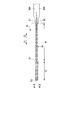
- FIG. 1 is a diagram showing a grasping treatment system 1.
- the grasping treatment system 1 includes a grasping treatment instrument 2.
- the grasping treatment instrument 2 has a longitudinal axis C.
- one of the two directions parallel to the longitudinal axis C is the distal direction (the direction of the arrow C1 in FIG. 1), and the opposite direction to the distal direction is the direction of the proximal direction (the arrow C2 in FIG. 1).
- the grasping treatment instrument 2 is a thermal treatment instrument that treats a treatment target such as a living tissue using heat as energy, and also treats the treatment target using high-frequency power (high-frequency current). It is.
- the grasping treatment instrument 2 includes a holding unit (handle unit) 3 and a cylindrical shaft (sheath) 5 connected to the distal direction side of the holding unit 3.
- the central axis of the shaft 5 is the longitudinal axis C.
- the holding unit 3 includes a cylindrical case portion 6 extending along the longitudinal axis C, and a fixed handle 7 extending from the cylindrical case portion 6 toward a certain direction intersecting the longitudinal axis C. And comprising.
- the cylindrical case part 6 is provided coaxially with the shaft 5, and the shaft 5 is attached to the holding unit 3 by being inserted into the cylindrical case part 6 from the distal direction side.
- the fixed handle 7 is formed integrally with the cylindrical case portion 6.
- the holding unit 3 includes a movable handle 8 that is rotatably attached to the cylindrical case portion 6. By rotating the movable handle 8 with respect to the cylindrical case portion 6, the movable handle 8 opens or closes the fixed handle 7.
- the grasping treatment system 1 includes an energy source unit 10 which is a power generator, for example.
- the other end of the cable 11 is connected to the energy source unit 10.
- the energy source unit 10 includes a thermal energy source (energy source) 12, a high frequency energy source 13, and a control unit 15.
- the thermal energy source 12 and the high frequency energy source 13 are, for example, output circuits that output electrical energy.
- the control unit 15 is formed of a processor including a CPU (Central Processing Unit) or an ASIC (Application Specific Integrated Circuit), for example.
- the energy source unit 10 is electrically connected to an energy operation input unit 16 such as a foot switch.
- a grasping treatment unit 20 is connected to the distal end side of the shaft 5.
- the grasping treatment unit 20 includes a first jaw 21 that is a first grasping portion, and a second jaw 22 that is a second grasping portion.
- the first jaw 21 and the second jaw 22 can be opened and closed. That is, the first jaw 21 and the second jaw 22 can be opened and closed relatively.
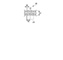
- FIG. 2 is a diagram showing a configuration of the distal end portion of the grasping treatment instrument 2 including the grasping treatment unit 20.
- FIG. 2 shows a state where the first jaw 21 and the second jaw 22 are open.
- FIG. 3 is a view showing the first jaw 21 and the second jaw 22 in a cross section perpendicular to the longitudinal axis C.
- FIG. FIG. 3 shows a state in which the space between the first jaw 21 and the second jaw 22 is closed.
- the first jaw 21 has a first jaw axis J1.
- the first jaw axis J1 is the central axis of the first jaw 21, and the first jaw (first gripping portion) 21 is along the first jaw axis J1 from the proximal end portion toward the distal end portion. It is extended.
- the two directions parallel to the first jaw axis J1 are the jaw longitudinal direction of the first jaw 21 (first jaw longitudinal direction).
- One of the jaw longitudinal directions (longitudinal direction) is the jaw tip direction (first jaw tip direction) of the first jaw 21, and the direction opposite to the jaw tip direction (first jaw tip direction) is the first direction.
- This is the jaw proximal direction of the jaw 21 (first jaw proximal direction).
- the jaw distal direction of the first jaw 21 coincides with the direction toward the distal end of the first jaw 21, and the jaw proximal direction of the first jaw 21 is the direction toward the proximal end of the first jaw 21. Matches.
- the second jaw 22 has a second jaw axis J2.
- the second jaw axis J2 is the central axis of the second jaw 22, and the second jaw (second gripping portion) 22 is along the second jaw axis J2 from the proximal end portion toward the distal end portion. It is extended.
- two directions parallel to the second jaw axis J2 become the jaw longitudinal direction of the second jaw 22 (second jaw longitudinal direction).
- one of the jaw longitudinal directions (longitudinal direction) is the jaw tip direction (second jaw tip direction) of the second jaw 22, and the direction opposite to the jaw tip direction (second jaw tip direction) is the second direction.
- This is the jaw proximal direction of the jaw 22 (second jaw proximal direction).
- the jaw distal direction of the second jaw 22 coincides with the direction toward the distal end of the second jaw 22, and the proximal direction of the jaw of the second jaw 22 is the direction toward the proximal end of the second jaw 22. Matches.
- the second jaw 22 is fixed to the shaft 5 at the tip of the shaft 5.
- the second jaw axis J ⁇ b> 2 is substantially parallel to the longitudinal axis C of the shaft 5.
- the first jaw 21 is attached to the tip of the shaft 5 via a fulcrum pin 23.
- the first jaw 21 is rotatable with respect to the shaft 5 about the fulcrum pin 23.
- a rod-like rod 25 extends from the proximal direction side toward the distal direction side inside the shaft 5.
- the rod 25 is movable along the longitudinal axis C with respect to the shaft 5.
- the base end portion of the rod 25 is connected to the movable handle 8 inside the cylindrical case portion 6.
- the tip of the rod 25 is connected to the first jaw 21 via the connection pin 26.
- the rod 25 moves along the longitudinal axis C with respect to the shaft 5.
- the first jaw 21 rotates with respect to the shaft 5, and the first jaw 21 opens or closes with respect to the second jaw 22.
- the second jaw 22 since the second jaw 22 is fixed to the shaft 5, the second jaw 22 opens or closes with respect to the first jaw 21. That is, the movement of the rod 25 relative to the shaft 5 opens or closes the gap between the first jaw 21 and the second jaw 22 in the grasping treatment unit 20.
- the movable handle 8 includes an opening / closing operation input unit for inputting an opening / closing operation for opening or closing between the first jaw (first holding unit) 21 and the second jaw (second holding unit) 22. Become.
- the direction toward the second jaw 22 in the first jaw 21 is the closing direction of the first jaw 21 (the direction of the arrow Y1 in FIGS. 2 and 3), and the second jaw in the first jaw 21.
- the direction away from 22 is the jaw opening direction of the first jaw 21 (the direction of the arrow Y2 in FIGS. 2 and 3).
- the jaw closing direction (first jaw closing direction) of the first jaw 21 is one direction intersecting (perpendicular to) the first jaw axis J1, and the jaw opening direction of the first jaw 21.
- the (first jaw opening direction) is the opposite direction to the jaw closing direction.
- the direction toward the first jaw 21 in the second jaw 22 is the jaw closing direction of the second jaw 22 (the direction of the arrow Y3 in FIGS.
- the direction away from 21 is the jaw opening direction of the second jaw 22 (the direction of the arrow Y4 in FIGS. 2 and 3).
- the jaw closing direction (second jaw closing direction) of the second jaw 22 is one direction intersecting (perpendicular to) the second jaw axis J2, and the jaw opening direction of the second jaw 22 The (second jaw opening direction) is opposite to the jaw closing direction.
- Two directions intersecting (perpendicular to) the first jaw axis J1 and perpendicular to the jaw opening direction and the jaw closing direction of the first jaw 21 are the jaw width direction (the direction of the arrow W1 in FIG. 3). And the direction of the arrow W2.
- the jaw width direction is a direction that intersects (perpendicular to) the second jaw axis J2 and is perpendicular to the jaw opening direction and the jaw closing direction of the second jaw 22.
- the second jaw 22 includes a support member (second support member) 31 fixed to the shaft 5 and a receiving member 32 fixed to the support member 31.
- the support member 31 and the receiving member 32 extend along the second jaw axis J ⁇ b> 2 from the proximal end portion to the distal end portion of the second jaw 21.
- the support member 31 forms a jaw rear surface (second jaw rear surface) 27 facing the jaw opening direction (second jaw opening direction) on the outer surface of the second jaw 22.
- a receiving member 32 is fixed on the side of the support member 31 in the jaw closing direction.
- the receiving member 32 is electrically formed from an insulating material.
- the receiving member 32 includes a base surface 33 that faces the jaw closing direction, and a protruding portion 35 that protrudes from the base surface 33 toward the jaw closing direction of the second jaw 22.
- the protruding portion 35 extends from the proximal end portion of the second jaw 22 to the distal end portion along the second jaw axis J2.
- the outer surface of the second jaw 22 is a surface exposed to the outside in the second jaw 22.
- the second jaw 22 includes an electrode member (second electrode member) 36 fixed to the receiving member 32 at the base surface 33.
- the electrode member 36 is fixed to the base surface 33 of the receiving member 32 from the jaw closing direction side of the second jaw 22.
- the electrode member 36 is made of a conductive material.
- the electrode member 36 extends along the second jaw axis J ⁇ b> 2 from the proximal end portion to the distal end portion of the second jaw 22, and is formed in a ring shape surrounding the protruding portion 35 of the receiving member 32.
- a power supply line (second high-frequency power supply line) 37 formed from electrical wiring or the like is connected to the base end portion of the electrode member 36.
- the power supply line 37 extends through the space between the shaft 5 and the rod 25, the inside of the cylindrical case portion 6, and the inside of the cable 11, and the other end is connected to the high frequency energy source 13 of the energy source unit 10.
- the high frequency power output from the high frequency energy source 13 is supplied to the electrode member 36 of the second jaw 22 through the power supply line 37.
- the electrode member 36 functions as one electrode (second electrode) of high-frequency power.
- the receiving member 32 is electrically formed from an insulating material, high-frequency power is not supplied (transmitted) to the support member 31 and the receiving member 32.
- a treatment surface (second treatment surface) facing the first jaw 21 on the outer surface of the second jaw 22 by the protruding portion 35 and the electrode member 36 of the receiving member 32. ) 28 is formed.
- the treatment surface (second treatment surface) 28 is a part of the outer surface of the second jaw 22 and faces the jaw closing direction (second jaw closing direction) of the second jaw 22.
- FIG. 4 is an exploded view of the first jaw 21 for each member.
- the first jaw 21 includes a support member (first support member) 41 attached to the shaft 5 and the rod 25, and a heat insulating member 42 fixed to the support member 41.
- the support member 41 and the heat insulating member 42 extend along the first jaw axis J ⁇ b> 1 from the base end portion of the first jaw 21 to the tip end portion.
- the support member 41 forms a jaw rear surface (first jaw rear surface) 51 facing the jaw opening direction (first jaw opening direction) on the outer surface of the first jaw 21.
- a heat insulating member 42 is fixed on the jaw closing direction side of the support member 41.
- the heat insulating member 42 is electrically formed from an insulating material.
- the outer surface of the first jaw 21 is a surface exposed to the outside in the first jaw 21.
- a blade (electrode member) 43 is fixed on the jaw closing direction side (first jaw closing direction side) of the heat insulating member 42.
- the blade 43 is made of a conductive material having a high heat transfer property.
- a cavity 45 is formed between the heat insulating member 42 and the blade 43 in the jaw opening direction (opening direction) and the jaw closing direction (closing direction). The cavity 45 is surrounded by the heat insulating member 42 and the blade 43.
- the treatment surface (first treatment surface) 52 is positioned at a position facing the treatment surface (second treatment surface) 28 of the second jaw 22 on the outer surface of the first jaw 21 by the blade 43. Is formed.
- the treatment surface (first treatment surface) 52 is a part of the outer surface of the first jaw 21 and faces the jaw closing direction (first jaw closing direction) of the first jaw 21.
- first high-frequency power supply line 53 formed from electrical wiring or the like is connected to the base end portion of the blade (incision portion) 43.
- the power supply line 53 extends through the space between the shaft 5 and the rod 25, the inside of the cylindrical case portion 6, and the inside of the cable 11, and the other end is connected to the high frequency energy source 13 of the energy source unit 10.
- High frequency power (high frequency electrical energy) output from the high frequency energy source 13 is supplied to the blade 43 of the first jaw 21 through the power supply line 53.
- the blade 43 functions as an electrode (first electrode) of high-frequency power having a potential different from that of the electrode member 36.
- the heat insulation member 42 is electrically formed from an insulating material, high frequency power is not supplied (transmitted) to the support member 41 and the heat insulation member 42.
- the treatment surface (grip surface) 52 formed by the blade 43 is in contact with the protrusion 35 of the receiving member 32 in a state in which the space between the first jaw 21 and the second jaw 22 is closed.
- a surface (contact portion) 55 is provided.
- the receiving member 32 is formed with a receiving surface 38 that receives the contact surface 55.
- the receiving surface 38 is a part of the treatment surface (gripping surface) 28 and is formed only from the receiving member 32.
- the blade 43 In a state where the contact surface 55 is in contact with the receiving surface 38, the blade 43 does not contact the electrode member 36 of the second jaw 22, and there is a gap between the blade 43 and the electrode member 36. This prevents contact between the electrode member 36 of the second jaw 22 and the blade 43 of the first jaw 21 having different potentials relative to each other.
- first jaw width direction the direction of the arrow W1 in FIG. 3
- second jaw width direction the direction opposite to the first jaw width direction
- first jaw width direction the direction of the arrow W1 in FIG. 3
- second jaw width direction the direction opposite to the first jaw width direction
- first treatment surface the direction of the arrow W1 in FIG. 3
- first jaw width direction the direction of the arrow W1 in FIG. 3
- second jaw width direction the direction opposite to the first jaw width direction
- second jaw width direction is defined as a second jaw width direction.
- the distance from the treatment surface 28 of the second jaw 22 becomes smaller toward the first jaw width direction.
- the blade 43 is formed in a shape in which the contact surface 55 protrudes from the inclined surfaces 57A and 57B toward the second jaw 22 (first jaw closing direction side).
- the heat generating part 40 is provided in the cavity 45 between the heat insulating member 42 and the blade 43.
- the heating unit 40 includes a heating wire (heater wire) 50 that is a heating element.
- the heat generating portion 40 is fixed to the heat insulating member 42 and is fixed to the blade 43.
- the exterior of the heat generating portion 40 is electrically formed from an insulating material. For this reason, the high frequency power supplied to the blade 43 is not supplied to the heating wire 50.
- the heat generating portion 40 (heat generating wire 50) is installed between the installation surface 46 of the heat insulating member 42 and the installation surface 47 of the blade 43.
- the heating surface 40 including the heating wire 50 is installed on the installation surfaces (contact surfaces) 46 and 47, and the heat generation unit 40 is in contact with the installation surfaces 46 and 47.
- the heat generating part 40 heat generating wire 50
- the first jaw 21 which is a heat generating jaw (heat generating gripping portion) is provided with only one heat generating wire 50, and a plurality of heat generating wires are not provided.
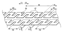
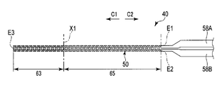
- FIG. 5 is a diagram showing the configuration of the heating wire 50 (heating unit 40).
- the heating wire 50 has a first extending end E1 and a second extending end E2 which are both ends of the heating wire 50 in the extending direction, and the first extending wire It continues without branching from the end E1 to the second extending end E2. That is, the heating wire 50 is continuous without branching from the first extended end E1 which is one end in the extending direction to the second extended end E2 which is the other end.
- the first extending end E ⁇ b> 1 and the second extending end E ⁇ b> 2 are located at the base end portion of the first jaw (heat generating jaw) 21.
- the heating wire 50 has a turn-back position E3 between the first extending end E1 and the second extending end E2.
- the folding position E3 is located at the tip of the first jaw 21.
- the heating wire 50 extends from the first extended end E1 to the turn-back position E3 toward the distal end side (jaw tip direction), and extends from the turn-back E3 to the second extended end E2 on the base end side (the jaw base). It extends toward the end direction. Therefore, the folding position E3 is a substantially intermediate position between the first extending end E1 and the second extending end E2. Since the heating wire 50 is extended as described above, the first jaw (heating gripping portion) 21 is provided with 50 heating wires over the range from the base end to the tip in the longitudinal direction of the jaw.
- the heat generating portion 40 (on the installation surface (the installation surface 46 of the heat insulating member 42 and the installation surface 47 of the blade 43) over the range from the proximal end to the distal end in the longitudinal direction of the jaw).
- a heating wire 50 is installed.
- first thermal power supply line first thermal power supply line
- second thermal power supply line second thermal power supply line
- the power supply lines 58 ⁇ / b> A and 58 ⁇ / b> B extend through the space between the shaft 5 and the rod 25, the inside of the cylindrical case portion 6, and the inside of the cable 11, and the other end is the thermal energy source 12 of the energy source unit 10. It is connected to the.
- the electric power (thermoelectric energy) output from the thermal energy source (energy source) 12 is supplied to the heating wire 50 of the first jaw 21 through the power supply lines 58A and 58B.
- a voltage potential difference
- a current flows through the heating wire (heater wire) 50.
- a current flows without being divided between the first extending end E1 and the second extending end E2.
- heat is generated by the thermal resistance of the heating wire 50.
- heat is generated over the entire length of the heating wire 50 from the first extending end E1 to the second extending end E2 in the extending direction of the heating wire 50.
- the heat generated in the heating wire 50 is transmitted to the treatment surface (first treatment surface) 52 of the blade 43 through the installation surface 47.
- the treatment target is treated by the heat transmitted to the treatment surface (gripping surface) 52.
- a temperature sensor (thermocouple) 61 that is a temperature detection unit that detects the temperature of the distal end portion of the treatment surface 52 is attached to the blade 43.
- One end of signal lines 62 ⁇ / b> A and 62 ⁇ / b> B formed from electric signal lines or the like is connected to the temperature sensor 61.
- the signal lines 62 ⁇ / b> A and 62 ⁇ / b> B extend through the space between the shaft 5 and the rod 25, the inside of the cylindrical case part 6, and the inside of the cable 11, and the other end is connected to the control part 15 of the energy source unit 10.
- a detection signal based on the detection result of the temperature sensor 61 is transmitted to the control unit 15 via the signal lines 62A and 62B.
- the control unit 15 controls the output state of electric power from the thermal energy source 12 based on the detected temperature of the distal end portion of the treatment surface 52.
- the heat generation line 50 includes a first heat generation region 63 and a second heat generation region 65 provided on the base end side (the jaw base end direction side) of the first heat generation region 63.
- the extended state of the heating wire 50 changes between the first heating area 63 and the second heating area 65. That is, the extended state of the heating wire 50 changes at the boundary position X1 between the first heating region 63 and the second heating region 65.
- the first heat generation region 63 is provided over a range from the distal end portion of the first jaw 21 to the boundary position X1
- the second heat generation region 65 is provided from the proximal end portion of the first jaw 21 to the boundary position X1. It is provided over the range.
- the first extending end E1 and the second extending end E2 of the heating wire 50 are located in the second heating region 65, and the folding position E3 of the heating wire 50 is located in the first heating region 63. is doing.
- the boundary position X ⁇ b> 1 coincides with an intermediate position in the longitudinal direction of the first jaw (heat generation gripping part) 21.
- the boundary position X1 is the dimension of one third of the total length in the longitudinal direction of the first jaw (heat generating jaw) 21 from the distal end side of the first jaw 21 to the proximal end side. Located away.
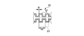
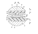
- FIG. 6 shows an extended state of the heating wire 50 in the first heating region 63
- FIG. 7 shows an extended state of the heating wire 50 in the second heating region 65.
- the line width of the heat generation line 50 is uniform at B0, for example, 0.1 mm. is there.
- the thickness of the heat generation line 50 is also uniform.
- the line width of the heating wire 50 is perpendicular to the extending direction of the heating wire 50 and parallel to the installation surface 46 (the installation surface 47 of the blade 43) of the heat insulating member 42 (that is, the heating wire 50).
- the thickness of the heating wire 50 is perpendicular to the extending direction of the heating wire 50 and perpendicular to the installation surface 46 (the installation surface 47 of the blade 43) of the heat insulating member 42 (that is, the heating wire 50).
- the pitch (repetition interval) P ⁇ b> 1 of the extended pattern 67 in the first heat generation region 63 is smaller than the pitch (repetition interval) P ⁇ b> 2 of the extension pattern 67 in the second heat generation region 65.
- the pitch P1 of the extended pattern 67 in the first heat generating region 63 is 0.3 mm
- the pitch P2 of the extended pattern 67 in the second heat generating region 65 is 0.5 mm.
- the pitch P1 of the extended pattern 67 is small in the first heat generation region 63, the number density (number) of the extension patterns 67 of the first heat generation region 63 per unit area ⁇ S of the installation surface 47 of the blade 43 is The number density (number) of the extended patterns 67 of the second heat generating region 65 per unit area ⁇ S of the installation surface 47 of the blade 43 is higher.
- the path length along the extending direction of the heating wire 50 per unit area ⁇ S of the installation surface 46) of 42 becomes longer.
- the path length of the heat generation line 50 is long, and thus the amount of heat generated from the heat generation line 50 per unit area ⁇ S of the installation surface 47 is larger than that in the second heat generation region 65. That is, in the first jaw (heat generation gripping portion) 21, in a state where heat is generated from the heat generation line 50 (heat generation portion 40), the heat generation line 50 from the heat generation line 50 per unit area ⁇ S of the installation surface 47 (installation surface 46). The amount of heat generated is greater at the distal end than at the proximal end.
- the first jaw 21 Compared with the region closer to the base end than the intermediate position (second heat generation region 65), the unit area ⁇ S of the installation surface (46, 47) in the region closer to the tip than the intermediate position (first heat generation region 63).
- the amount of heat generated from the heating line 50 at the periphery increases.
- the amount of heat generated from the heat generation line 50 per unit area ⁇ S is larger at the distal end than at the proximal end, so that the treatment surface (first treatment surface) 52 is at the proximal end.
- the amount of heat transferred from the heat generating portion 40 is increased.
- the grasping treatment unit 20 (first jaw 21 and second jaw 22) is inserted into the body, and the first jaw 21 and the first jaw 21 A treatment target is disposed between the two jaws 22.
- the movable handle 8 is closed with respect to the fixed handle 7 and an opening / closing operation of the grasping treatment unit 20 is input.
- the space between the first jaw 21 and the second jaw 22 is closed, and the treatment target is gripped between the first jaw 21 and the second jaw 22.
- An energy operation is input by the energy operation input unit 16 while the treatment target is held.
- power thermoelectric energy
- high frequency power high frequency electrical energy
- the treatment target in contact with the treatment surface (gripping surface) 52 is heated and the treatment target is incised.
- the treatment target is solidified.
- the amount of heat generated by the heating wire 50 can be adjusted by adjusting the power supplied to the heating wire 50.
- the temperature of the treatment surface 52 is about 230 ° C. to 350 ° C., and preferably about 250 ° C. to 300 ° C.
- the temperature of the treatment surface 52 is about 200 ° C. Therefore, in the treatment using the heat generated by the heating wire 50, the temperature of the treatment surface 52 is 200 ° C. or more and 350 ° C. or less.
- the electrode member 36 and the blade 43 have different potentials with respect to each other. Function. Thereby, a high-frequency current flows between the electrode member 36 and the blade 43 through the treatment target (living tissue) grasped between the first jaw 21 and the second jaw 22. The object to be treated is denatured and coagulation is promoted by the high-frequency current.
- the front end portions of the first jaw 21 and the second jaw 22 (for example, in the first jaw 21 and the second jaw 22, the total length from the front end in the jaw longitudinal direction). (A range that covers about one third of the size) is brought into contact with the treatment object, and treatment (small bite method) is performed in which the treatment object is repeatedly incised using heat.
- treatment small bite method
- the first jaw (heat generation jaw) 21 provided with the heating wire 50 (heat generation portion 40) only the tip portion contacts the treatment target.
- the heat generation amount from the heat generation line 50 per unit area ⁇ S of the installation surface 47 (installation surface 46) is Larger at the tip than at the base.
- the amount of heat transferred from the heat generating portion 40 is greater at the distal end than at the proximal end.
- the amount of heat transferred to the tip of the treatment surface (first treatment surface) 52 is large. Therefore, a temperature drop at the distal end portion of the treatment surface 52 (the distal end portion of the first jaw 21) is suppressed. Since the temperature of the distal end portion of the treatment surface (gripping surface) 52 is maintained without lowering, the incisibility of the treatment target is ensured and the treatment can be performed quickly.
- the amount of heat generated from the heating wire 50 at the tip of the first jaw 21 does not increase by increasing the power to the heating wire 50. That is, in a state where the heat generation amount from the heating wire 50 becomes large at the distal end portion of the first jaw 21, the heat generation amount from the heating wire 50 is kept small at the proximal end portion of the first jaw 21. Therefore, in the treatment (small bite method), it is suppressed that the temperature at the base end portion of the first jaw 21 that does not come into contact with the treatment target (that is, heat is not radiated to the treatment target) becomes excessively high. Is done.
- the heating wire 50 provided only in the first jaw (heat generating jaw) 21, and only at the tip end portion (first heat generating region 63) of the first jaw 21.
- the amount of heat generated from the heating wire 50 can be increased.
- the first jaw (22) is provided with a plurality of heating lines (heating elements), and the power supply state through the corresponding power supply line to each heating line is controlled, whereby the first jaw (22 ), It is possible to increase the heat generation amount (temperature) only at the tip.
- the configuration of the wiring and the like between each heating element and the power source becomes complicated, and the control of the output state of the power from the power source becomes complicated. That is, in the present embodiment, it is possible to increase the amount of heat generated from the heating wire 50 only at the distal end portion (first heat generation region 63) of the first jaw 21 with an easy configuration and easy power output control. Realized.
- the temperature of the distal end portion of the treatment surface (first treatment surface) 52 is detected by the temperature sensor 61, and the control unit 18 determines the electric power from the thermal energy source 12 based on the temperature detection result.
- the output state is controlled. Therefore, by controlling the output state of the electric power from the thermal energy source 12, the temperature of the distal end portion of the treatment surface (gripping surface) 52 is set to a target temperature (for example, 250 ° C.) suitable for treatment (small bite method). Can be adjusted easily.
- the energy source unit 10 may be provided with a memory (not shown) or the like, and the relationship between the target temperature and power and the temperature of the distal end portion of the treatment surface 52 may be stored.
- the pitch (repetition interval) P1 of the extended pattern 67 in the first heat generation region 63 is set to be greater than the pitch (repetition interval) P2 of the extension pattern 67 in the second heat generation region 65.
- FIGS. 8 is a diagram showing the configuration of the heating wire 50 (heating unit 40) of this modification.
- FIG. 9 shows an extended state of the heating line 50 in the first heating area 63 of the present modification
- FIG. 10 shows an extension of the heating line 50 in the second heating area 65 of the present modification. Indicates the state. As shown in FIGS.
- the line width of the heating line 50 is uniform at B0 in the first heating area 63 and the second heating area 65, as in the first embodiment. Yes, for example, 0.1 mm. Further, in the first heat generation region 63 and the second heat generation region 65, the thickness of the heat generation line 50 is also uniform.
- the pitch of the extended pattern 67 in the first heat generating region 63 and the pitch of the extended pattern 67 in the second heat generating region 65 are uniform at P0. For example, 0.4 mm.
- the dimensions of the first jaw (heat generating jaw) 21 in the jaw width direction are the first heat generating region 63 and the second heat generating region 65.
- the dimension L1 of the first heat generating region 63 in the jaw width direction is larger than the dimension L2 of the second heat generating region 65 in the jaw width direction.
- the dimension L1 of the first heat generating region 63 in the jaw width direction is 0.8 mm
- the dimension L2 of the second heat generating region 65 in the jaw width direction is 0.6 mm.
- the second heat generating region 65 (the base end of the first jaw 21) is formed in the first heat generating region 63 (the distal end portion of the first jaw 21).
- the path length along the extending direction of the heating wire 50 per unit area ⁇ S of the installation surface 47 of the blade 43 (the installation surface 46 of the heat insulating member 42) is longer than that of the portion.
- the path length of the heat generation line 50 is long, and thus the amount of heat generated from the heat generation line 50 per unit area ⁇ S of the installation surface 47 is larger than that in the second heat generation region 65.
- the unit area ⁇ S of the installation surface 47 (installation surface 46) in a state where heat is generated from the heating wire 50 is larger at the distal end than at the proximal end.
- FIGS. 11 to 13 the path length along the extending direction of the heating wire 50 per unit area ⁇ S of the installation surface 47 of the blade 43 (the installation surface 46 of the heat insulating member 42). However, it becomes uniform in the first heat generation region 63 and the second heat generation region 65. Accordingly, in the first heat generation region 63 and the second heat generation region 65, the pitch of the extended pattern 67 is uniform at P0, for example, 0.4 mm.
- the dimension of the first heat generating area 63 in the jaw width direction is the same as the dimension of the second heat generating area 65 in the jaw width direction.
- FIG. 11 is a diagram showing the configuration of the heating wire 50 (heating unit 40) of this modification.
- FIG. 12 shows an extended state of the heating line 50 in the first heating area 63 of the present modification
- FIG. 13 shows an extension of the heating line 50 in the second heating area 65 of the present modification. Indicates the state.
- the line width B1 of the heating line 50 in the first heating area 63 is smaller than the line width B2 of the heating line 50 in the second heating area 65.
- the line width B1 of the heat generation line 50 in the first heat generation region 63 is 0.05 mm
- the line width B2 of the heat generation line 50 in the second heat generation region 65 is 0.1 mm.
- the thickness of the heating line 50 is uniform in the first heating area 63 and the second heating area 65.
- the unit area ⁇ S of the installation surface 47 (installation surface 46) is the same as in the first embodiment.
- the amount of heat generated from the heating wire 50 at the top is greater at the tip than at the base.
- the thickness T1 of the heating wire 50 in the first heating area 63 is smaller than the thickness T2 of the heating wire 50 in the second heating area 65.
- the thickness T1 of the heating line 50 in the first heating area 63 is 0.01 mm
- the thickness T2 of the heating line 50 in the second heating area 65 is 0.02 mm.
- the line width of the heat generation line 50 is uniform at B0, for example, 0.1 mm.
- the path length along the extending direction of the heating wire 50 per unit area ⁇ S of the installation surface 47 of the blade 43 (the installation surface 46 of the heat insulating member 42) is The first heat generation area 63 and the second heat generation area 65 are uniform.
- the second heat generation region 65 (first jaw 21) is also formed in the first heat generation region 63 (the tip of the first jaw 21) in the present modification as in the second modification. 21), the cross-sectional area perpendicular to the extending direction of the heating wire 50 is smaller.
- the heat generation amount from the heat generation line 50 per unit area ⁇ S of the installation surface 47 is larger than that in the second heat generation region 65. Therefore, in the present modification as well, in the first jaw (heat generating jaw) 21, in the state where heat is generated from the heating wire 50, the unit area ⁇ S of the installation surface 47 (installation surface 46) is the same as in the first embodiment.
- the amount of heat generated from the heating wire 50 at the top is greater at the tip than at the base.
- the path length along the extending direction of the heating wire 50 per unit area ⁇ S of the installation surface 47 of the blade 43 (the installation surface 46 of the heat insulating member 42), and The cross-sectional area perpendicular to the extending direction of the heating lines 50 is uniform in the first heating area 63 and the second heating area 65.
- the material forming the heating line 50 varies between the first heating area 63 and the second heating area 65. That is, in the first jaw (heat generation gripping portion) 21, the electric resistance of the material forming the heat generation line 50 is higher in the first heat generation region 63 (tip portion) than in the second heat generation region 65 (base end portion). Become.
- the heating line 50 is formed from stainless steel in the second heating area 65, whereas the heating line 50 is formed from nichrome having a higher electrical resistance than stainless steel in the first heating area 63.
- the first heating area 63 is indicated by dot-shaped hatching, and the second heating area is indicated by plain color without hatching.
- the electric resistance of the heating wire 50 is high in the first heat generating region 63, the amount of heat generated from the heating wire 50 per unit area ⁇ S of the installation surface 47 becomes the second heat generating region 65. Compared to larger. Therefore, in the present modification as well, in the first jaw (heat generating jaw) 21, in the state where heat is generated from the heating wire 50, the unit area ⁇ S of the installation surface 47 (installation surface 46) is the same as in the first embodiment. The amount of heat generated from the heating wire 50 at the top is greater at the tip than at the base.
- the extended state of the heating wire 50, the cross-sectional area of the heating wire 50, and the like change at the boundary position X1 between the first heating region 63 and the second heating region 65. It is not limited to.
- the heat generation line 50 of the first jaw (heat generation jaw) 21 from the base end (jaw base end direction) to the front end (jaw tip direction).
- the pitch (repetition interval) P of the extended pattern 67 may be gradually decreased (that is, may be gradually decreased).
- the heating line 50 is shown in a linear shape, but in this modified example, the heating line 50 has a line width as in the above-described embodiment.
- the pitch P of the extended pattern 67 gradually decreases from the proximal end portion to the distal end portion of the first jaw 21, so that the extended pattern 67 per unit area ⁇ S of the installation surface 47 of the blade 43 is reduced.
- the number density (number) gradually increases from the proximal end portion of the first jaw 21 toward the distal end portion.
- the first jaw (heat generation gripping portion) 21 the heat generation amount from the heat generation line 50 per unit area ⁇ S of the installation surface 47 gradually increases (becomes larger) from the base end portion toward the tip end portion. .)
- the first jaw (heat generating jaw) 21 also has the installation surface 47 (installation) in a state in which heat is generated from the heating wire 50 in the present modification as in the first embodiment.
- the amount of heat generated from the heating line 50 per unit area ⁇ S of the surface 46) is greater at the distal end than at the proximal end.
- the first jaw (heating jaw) 21 is installed from the proximal end portion toward the distal end portion.
- the amount of heat generated from the heating line 50 per unit area ⁇ S of the surface 47 (installation surface 46) may be gradually increased.
- the line width of the heating wire 50 is gradually reduced from the base end portion toward the distal end portion in the first jaw (heat generation gripping portion) 21.
- the amount of heat generated from the heating wire 50 per unit area ⁇ S of the installation surface 47 gradually increases (becomes larger) from the base end portion toward the tip end portion.
- the heating wire 50 in the jaw longitudinal direction (longitudinal direction) of the first jaw (heating jaw) 21 has a unit area ⁇ S of the installation surface 47 (installation surface 46).
- the heat generation amount from the heat generation line 50 may be divided into three heat generation regions (regions) 71 to 73 that are different from each other.
- the first heat generation region 71 is located at the distal end portion of the first jaw 21, and the second heat generation region 72 is continuous to the jaw base end direction side of the first heat generation region 71.
- the third heat generation region 73 is continuous with the second heat generation region 72 on the jaw proximal end side, and is located at the proximal end portion of the first jaw 21.
- the heating line 50 is shown as a line, but the heating line 50 also has a line width in the present modification as in the above-described embodiment.
- the boundary between the first heat generation area 71 and the second heat generation area 72 and the boundary position X3 between the second heat generation area 72 and the third heat generation area 73 are The extended state changes. That is, in this modification, the pitch (repetition interval) P3 of the extended pattern 67 in the first heat generation region 71 is smaller than the pitch (repetition interval) P4 of the extension pattern 67 in the second heat generation region 72. Become. The pitch (repetition interval) P4 of the extended pattern 67 in the second heat generation region 72 is smaller than the pitch (repetition interval) P5 of the extension pattern 67 in the third heat generation region 73.
- the heat generation amount from the heat generation line 50 per unit area ⁇ S of the installation surface 47 (installation surface 46) is larger in the first heat generation region 71 than in the second heat generation region 72, and The second heat generation area 72 is larger than the third heat generation area 73. That is, the heat generation amount from the heat generation line 50 per unit area ⁇ S of the installation surface 47 increases as the region located on the tip side (the jaw tip direction side) among the three heat generation regions (regions) 71 to 73 increases. .
- the first jaw (heat generating jaw) 21 also has the installation surface 47 (installation) in a state in which heat is generated from the heating wire 50 in the present modification as in the first embodiment.
- the amount of heat generated from the heating line 50 per unit area ⁇ S of the surface 46) is greater at the distal end than at the proximal end.
- the amount of heat generated from the heat generation line 50 around ⁇ S may be larger than the second heat generation region 72 in the first heat generation region 71 and larger than the third heat generation region 73 in the second heat generation region 72.
- the heat generation amount from the heat generation line 50 per unit area ⁇ S of the installation surface 47 is changed to the second heat generation in the first heat generation region 71.
- the second heat generation area 72 is larger than the third heat generation area 73.
- the heat generation line 50 in the longitudinal direction (longitudinal direction) of the first jaw (heat generation jaw) 21 has a heat generation amount from the heat generation line 50 per unit area ⁇ S of the installation surface 47 (installation surface 46). It may be divided into four or more different heat generation regions (regions). Also in this case, as in the sixth modified example in which the heating wire 50 is divided into three heating regions 71 to 73, the region located closer to the tip side (the jaw tip direction side) in the heating region (region). The amount of heat generated from the heating wire 50 per unit area ⁇ S of the installation surface 47 increases.
- a first jaw (first gripping portion) 21 provided with a heat generating portion 40 may be fixed to the shaft 5.
- the second jaw 22 not provided with the heat generating portion 40 is attached to the shaft 5 so as to be rotatable.
- the second jaw 22 is formed of a support member 31, a receiving member 32, and an electrode member 36 in the present modification as well as in the first embodiment.
- a treatment surface (second treatment surface) 28 that faces the first jaw 21 is formed by the receiving member 32 and the electrode member 36.
- the first jaw 21 is formed of a support member 41, a heat insulating member 42, a blade 43, and a heat generating portion 40, as in the first embodiment.
- the blade 43 forms a treatment surface (first treatment surface) 52 that faces the second jaw 22.
- the first jaw (heat generating jaw) 21 is provided with only one heating wire 50.
- a heating wire 50 is extended in the same manner as in the first embodiment.
- the unit area of the installation surface 47 (installation surface 46) in a state where heat is generated from the heating wire 50 is also in the present modification, as in the first embodiment, in the first jaw 21 which is the heat generation gripping part, the unit area of the installation surface 47 (installation surface 46) in a state where heat is generated from the heating wire 50.
- the amount of heat generated from the heating wire 50 around ⁇ S is greater at the tip than at the base. Therefore, in the treatment surface (first treatment surface) 52, the amount of heat transferred from the heat generating portion 40 is greater at the distal end than at the proximal end.
- both the first jaw 21 and the second jaw 22 are heat generating jaws provided with the heat generating portion (40).
- each heating jaw (21, 22) is provided with only one heating wire (50).
- the heating wire (50) is extended in the same manner as the first jaw 21 in the above-described embodiment or the like. .
- each of the heat generating jaws (21, 22) has the installation surface 47 (installation surface 46) in a state where heat is generated from the heat generation wire 50.
- the amount of heat generated from the heating wire 50 per unit area ⁇ S is greater at the tip than at the base.
- one of the two jaws (21, 22) (for example, the second jaw 22) is fixed to the shaft 5 and the other of the two jaws (21, 22) (for example, the first jaw).
- the jaw 21) is rotatable with respect to the shaft 5, but is not limited thereto.
- both the first jaw 21 and the second jaw 22 may be pivotally attached to the shaft 5. In this case, by moving the rod 25 along the longitudinal axis C, both the first jaw 21 and the second jaw 22 rotate with respect to the shaft 5. Thereby, in the grasping treatment unit 20, the space between the first jaw 21 and the second jaw 22 is opened or closed.
- the high frequency energy source 13 is provided in the energy source unit 10, but the present invention is not limited to this. That is, it is not necessary to supply high frequency power to the first jaw 21 and the second jaw 22. Therefore, at least the heating wire 50 is provided in the first jaw 21 which is one of the two gripping portions (21, 22), and the energy source unit 10 outputs a heat energy source that outputs power supplied to the heating wire 50. 12 should just be provided.
- the first jaw (21) can be opened and closed between the first jaw (21) and the second jaw (22) in the grasping treatment unit (20).
- the heating wire (50) continues without branching from the first extending end (E1) to the second extending end (E2), and from the first extending end (E1) when current flows.
- Heat is generated over the entire length up to the second extended end (E2).
- the heat generating part (40) in a state where heat is generated from the heat generating line (50), the amount of heat generated per unit area is larger at the distal end than at the base end of the first jaw (21). For this reason, in the treatment surface (52) provided in the state which opposes the 2nd jaw (22) in the 1st jaw (21), the heat transfer amount transmitted from the heat generating part (40) is from the base end part. It becomes larger at the tip.
Abstract
Description
本発明の第1の実施形態について、図1乃至図7を参照して説明する。 (First embodiment)
A first embodiment of the present invention will be described with reference to FIGS.
なお、第1の実施形態では、第1の発熱領域63での延設パターン67のピッチ(繰返し間隔)P1を、第2の発熱領域65での延設パターン67のピッチ(繰返し間隔)P2より、小さくしているが、これに限るものではない。例えば、第1の変形例を図8乃至図10を参照にして、説明する。図8は、本変形例の発熱線50(発熱部40)の構成を示す図である。また、図9は、本変形例の第1の発熱領域63での発熱線50の延設状態を示し、図10は、本変形例の第2の発熱領域65での発熱線50の延設状態を示している。図8乃至図10に示すように、本変形例では第1の実施形態と同様に、第1の発熱領域63及び第2の発熱領域65において、発熱線50の線幅は、B0で均一であり、例えば、0.1mmである。また、第1の発熱領域63及び第2の発熱領域65において、発熱線50の線厚も、均一である。 (Modification)
In the first embodiment, the pitch (repetition interval) P1 of the
Claims (13)
- 生体組織を把持して処置する把持処置ユニットにおいて、
基端部から先端部に向かって延設され、外部に対して露出する外表面を有する第1のジョーと、
基端部から先端部に向かって延設され、前記第1のジョーとの間が開閉可能な第2のジョーと、
前記第1のジョーにおいて前記基端部から前記先端部までの範囲に渡って設置され、延設方向について一端である第1の延設端から他端である第2の延設端まで分岐することなく連続するとともに、電流が流れることにより前記第1の延設端から前記第2の延設端までの全長に渡って熱が発生する発熱線を備え、前記発熱線から前記熱が発生する状態において、単位面積あたりでの発熱量が前記第1のジョーの前記基端部より前記先端部で大きくなる発熱部と、
前記第1のジョーの前記外表面に設けられるとともに、前記第2のジョーに対して対向し、前記発熱部から伝達される伝熱量が基端部より先端部で大きくなる状態で前記生体組織を処置する処置面と、
を具備する、把持処置ユニット。 In a grasping treatment unit for grasping and treating a living tissue,
A first jaw extending from the proximal end toward the distal end and having an outer surface exposed to the outside;
A second jaw that extends from the base end toward the tip and can be opened and closed with the first jaw;
The first jaw is installed over a range from the base end portion to the tip end portion, and branches from a first extending end that is one end to a second extending end that is the other end in the extending direction. A heating line that generates heat over the entire length from the first extending end to the second extending end when current flows, and the heat is generated from the heating line. In the state, a heat generation unit in which a heat generation amount per unit area is larger at the distal end than the base end of the first jaw
The living tissue is provided on the outer surface of the first jaw, is opposed to the second jaw, and the amount of heat transferred from the heat generating portion is larger at the distal end than at the proximal end. A treatment surface to treat,
A grasping treatment unit comprising: - 前記第1のジョーは、前記処置面を形成するとともに、前記処置面に伝達された前記熱によって前記生体組織を切開する切開部を備える、請求項1の把持処置ユニット。 The grasping treatment unit according to claim 1, wherein the first jaw includes an incision portion that forms the treatment surface and incises the living tissue by the heat transmitted to the treatment surface.
- 前記発熱線で前記熱が発生した前記状態での前記処置面の温度が、200℃以上350℃以下となる、請求項1の把持処置ユニット。 The grasping treatment unit according to claim 1, wherein a temperature of the treatment surface in the state where the heat is generated by the heating wire is 200 ° C or higher and 350 ° C or lower.
- 前記発熱部では、前記単位面積あたりでの前記発熱線の前記延設方向に沿った経路長が、前記第1のジョーの前記基端部より前記先端部で長くなる、請求項1の把持処置ユニット。 2. The grasping treatment according to claim 1, wherein in the heat generating portion, a path length along the extending direction of the heat generating line per unit area is longer at the distal end portion than at the proximal end portion of the first jaw. unit.
- 前記発熱部では、前記発熱線の前記延設方向に垂直な断面積が、前記第1のジョーの前記基端部より前記先端部で小さくなる、請求項1の把持処置ユニット。 The grasping treatment unit according to claim 1, wherein in the heat generating portion, a cross-sectional area perpendicular to the extending direction of the heat generating wire is smaller at the distal end portion than at the proximal end portion of the first jaw.
- 前記発熱部では、前記発熱線を形成する材料の電気抵抗が、前記第1のジョーの前記基端部より前記先端部で高くなる、請求項1の把持処置ユニット。 The grasping treatment unit according to claim 1, wherein in the heat generating portion, an electric resistance of a material forming the heat generating wire is higher at the distal end portion than at the proximal end portion of the first jaw.
- 前記発熱部では、前記第1のジョーの前記基端部から前記先端部に向に向かって、前記単位面積あたりでの前記発熱線からの前記発熱量が漸増する、請求項1の把持処置ユニット。 2. The grasping treatment unit according to claim 1, wherein in the heat generating portion, the amount of heat generated from the heat generating line per unit area gradually increases from the base end portion of the first jaw toward the tip end portion. .
- 前記第1のジョーにおいて長手方向についての中間位置を規定した場合に、前記発熱部では、前記中間位置より基端部側の領域に比べて前記中間位置より先端部側の領域で、前記単位面積あたりでの前記発熱線からの前記発熱量が大きくなる、請求項1の把持処置ユニット。 When the intermediate position in the longitudinal direction is defined in the first jaw, the unit area of the heat generating portion is greater in the region closer to the distal end than the intermediate position than in the region closer to the proximal end than the intermediate position. The grasping treatment unit according to claim 1, wherein the amount of heat generated from the heating wire at the periphery increases.
- 前記発熱部は、前記単位面積あたりでの前記発熱線からの前記発熱量が互いに対して異なる3以上の領域に長手方向について分割され、
前記3以上の領域では、先端部側に位置する領域ほど、前記単位面積あたりでの前記発熱線からの前記発熱量が大きくなる、
請求項1の把持処置ユニット。 The heat generation part is divided in the longitudinal direction into three or more regions where the heat generation amount from the heat generation line per unit area is different from each other,
In the three or more regions, the heat generation amount from the heat generation line per unit area increases as the region is located on the tip side.
The grasping treatment unit according to claim 1. - 前記発熱線は、前記第1の延設端と前記第2の延設端との間に折返し位置を有し、
前記発熱線の前記第1の延設端及び前記第2の延設端は、前記第1のジョーにおいて前記基端部に位置し、
前記発熱線の前記折返し位置は、前記第1のジョーにおいて前記先端部に位置し、
前記発熱線は、前記第1の延設端から前記折返し位置まで先端部側に向かって延設され、前記折返し位置から前記第2の延設端まで基端部側に向かって延設される、
請求項1の把持処置ユニット。 The heating wire has a folding position between the first extending end and the second extending end;
The first extending end and the second extending end of the heating wire are located at the base end portion in the first jaw,
The folding position of the heating wire is located at the tip of the first jaw,
The heating wire extends from the first extended end to the folded position toward the distal end, and extends from the folded position to the second extended end toward the proximal end. ,
The grasping treatment unit according to claim 1. - 請求項1の把持処置ユニットと、
前記把持処置ユニットより基端方向側に設けられ、保持可能な保持ユニットと、
前記保持ユニットに設けられ、前記把持処置ユニットの前記第1のジョーと前記第2のジョーとの間を開く又は閉じる開閉操作が入力される開閉操作入力部と、
を具備する把持処置具。 A grasping treatment unit according to claim 1;
A holding unit provided on the proximal direction side from the grasping treatment unit and capable of holding;
An opening / closing operation input unit provided in the holding unit, to which an opening / closing operation for opening or closing between the first jaw and the second jaw of the grasping treatment unit is input;
A grasping treatment instrument comprising: - 請求項1の把持処置ユニットと、
前記第1の延設端及び前記第2の延設端を通して前記発熱線に供給される電力を出力し、前記電力を出力することにより、前記発熱線に前記電流を流すエネルギー源と、
を具備する把持処置システム。 A grasping treatment unit according to claim 1;
An energy source that outputs power supplied to the heating wire through the first extending end and the second extending end, and outputs the power to flow the current through the heating wire;
A grasping treatment system comprising: - 前記処置面の前記先端部の温度を検出する温度検出部と、
検出された前記処置面の前記先端部の前記温度に基づいて、前記処置面の前記先端部の前記温度が目標温度になる状態に、前記エネルギー源からの前記電力の出力状態を制御する制御部と、
をさらに具備する、請求項12の把持処置システム。 A temperature detector that detects the temperature of the tip of the treatment surface;
A control unit that controls the output state of the electric power from the energy source so that the temperature of the distal end portion of the treatment surface becomes a target temperature based on the detected temperature of the distal end portion of the treatment surface. When,
The grasping treatment system of claim 12, further comprising:
Priority Applications (4)
| Application Number | Priority Date | Filing Date | Title |
|---|---|---|---|
| EP15838397.6A EP3189805B1 (en) | 2014-09-05 | 2015-07-22 | Grasping treatment unit, grasping treatment instrument, and grasping treatment system |
| JP2016520118A JP5977908B2 (en) | 2014-09-05 | 2015-07-22 | Grasping treatment unit, grasping treatment instrument, and grasping treatment system |
| CN201580021018.2A CN106232042A (en) | 2014-09-05 | 2015-07-22 | Hold disposal unit, hold treatment apparatus and hold disposal system |
| US15/279,137 US9949781B2 (en) | 2014-09-05 | 2016-09-28 | Grasping treatment unit, grasping treatment instrument, and grasping treatment system |
Applications Claiming Priority (2)
| Application Number | Priority Date | Filing Date | Title |
|---|---|---|---|
| JP2014-181414 | 2014-09-05 | ||
| JP2014181414 | 2014-09-05 |
Related Child Applications (1)
| Application Number | Title | Priority Date | Filing Date |
|---|---|---|---|
| US15/279,137 Continuation US9949781B2 (en) | 2014-09-05 | 2016-09-28 | Grasping treatment unit, grasping treatment instrument, and grasping treatment system |
Publications (1)
| Publication Number | Publication Date |
|---|---|
| WO2016035471A1 true WO2016035471A1 (en) | 2016-03-10 |
Family
ID=55439540
Family Applications (1)
| Application Number | Title | Priority Date | Filing Date |
|---|---|---|---|
| PCT/JP2015/070886 WO2016035471A1 (en) | 2014-09-05 | 2015-07-22 | Surgical clamping unit, surgical clamping tool, and surgical clamping system |
Country Status (5)
| Country | Link |
|---|---|
| US (1) | US9949781B2 (en) |
| EP (1) | EP3189805B1 (en) |
| JP (1) | JP5977908B2 (en) |
| CN (1) | CN106232042A (en) |
| WO (1) | WO2016035471A1 (en) |
Cited By (4)
| Publication number | Priority date | Publication date | Assignee | Title |
|---|---|---|---|---|
| WO2018185815A1 (en) * | 2017-04-03 | 2018-10-11 | オリンパス株式会社 | Heat treatment tool |
| WO2019097608A1 (en) * | 2017-11-15 | 2019-05-23 | オリンパス株式会社 | Medical device |
| CN109963520A (en) * | 2016-11-18 | 2019-07-02 | 奥林巴斯株式会社 | Energy treatment apparatus |
| CN110234283A (en) * | 2017-01-18 | 2019-09-13 | 奥林巴斯株式会社 | Treatment apparatus |
Families Citing this family (5)
| Publication number | Priority date | Publication date | Assignee | Title |
|---|---|---|---|---|
| WO2018131126A1 (en) * | 2017-01-12 | 2018-07-19 | オリンパス株式会社 | Heat treatment tool |
| GB201709835D0 (en) * | 2017-06-20 | 2017-08-02 | Alesi Surgical Ltd | Surgical Assembly, system and electrode assembly |
| DE102019108140A1 (en) * | 2019-03-28 | 2020-10-01 | Karl Storz Se & Co. Kg | Bipolar electrosurgical tool |
| CN110432981A (en) * | 2019-09-05 | 2019-11-12 | 成都美创医疗科技股份有限公司 | A kind of surgical clamp |
| CN110432982A (en) * | 2019-09-05 | 2019-11-12 | 成都美创医疗科技股份有限公司 | A kind of coagulation cutting pincers |
Citations (6)
| Publication number | Priority date | Publication date | Assignee | Title |
|---|---|---|---|---|
| JPH0259356A (en) * | 1988-08-25 | 1990-02-28 | Toshiba Lighting & Technol Corp | Heating element |
| JPH08250266A (en) * | 1995-03-15 | 1996-09-27 | Ushio Inc | Rod heater |
| JP2004188012A (en) * | 2002-12-12 | 2004-07-08 | Olympus Corp | Medical instrument |
| JP2008503290A (en) * | 2004-06-23 | 2008-02-07 | アエスキュラップ アーゲー ウント ツェーオー カーゲー | Surgical instruments |
| EP2535013A1 (en) * | 2011-06-17 | 2012-12-19 | Tyco Healthcare Group LP | Tissue sealing forceps |
| JP2014144183A (en) * | 2013-01-30 | 2014-08-14 | Olympus Corp | Therapeutic treatment device |
Family Cites Families (8)
| Publication number | Priority date | Publication date | Assignee | Title |
|---|---|---|---|---|
| US4527560A (en) * | 1982-10-27 | 1985-07-09 | Masreliez Carl J | Medical or dental probe with self-heating tip and methods for making |
| JPH0632276B2 (en) * | 1988-08-30 | 1994-04-27 | 東芝ライテック株式会社 | Heating body |
| JP3349139B2 (en) * | 2000-01-20 | 2002-11-20 | オリンパス光学工業株式会社 | Coagulation incision system |
| US7458969B2 (en) * | 2002-05-06 | 2008-12-02 | Olympus Corporation | Therapeutic device for tissue from living body |
| JP2004144183A (en) * | 2002-10-24 | 2004-05-20 | Ntn Corp | Radial rolling bearing |
| US9402679B2 (en) * | 2008-05-27 | 2016-08-02 | Maquet Cardiovascular Llc | Surgical instrument and method |
| JP5631716B2 (en) * | 2010-12-14 | 2014-11-26 | オリンパス株式会社 | Therapeutic treatment device |
| JP2012161565A (en) | 2011-02-09 | 2012-08-30 | Olympus Medical Systems Corp | Therapeutical treatment device |
-
2015
- 2015-07-22 JP JP2016520118A patent/JP5977908B2/en active Active
- 2015-07-22 CN CN201580021018.2A patent/CN106232042A/en active Pending
- 2015-07-22 WO PCT/JP2015/070886 patent/WO2016035471A1/en active Application Filing
- 2015-07-22 EP EP15838397.6A patent/EP3189805B1/en active Active
-
2016
- 2016-09-28 US US15/279,137 patent/US9949781B2/en active Active
Patent Citations (6)
| Publication number | Priority date | Publication date | Assignee | Title |
|---|---|---|---|---|
| JPH0259356A (en) * | 1988-08-25 | 1990-02-28 | Toshiba Lighting & Technol Corp | Heating element |
| JPH08250266A (en) * | 1995-03-15 | 1996-09-27 | Ushio Inc | Rod heater |
| JP2004188012A (en) * | 2002-12-12 | 2004-07-08 | Olympus Corp | Medical instrument |
| JP2008503290A (en) * | 2004-06-23 | 2008-02-07 | アエスキュラップ アーゲー ウント ツェーオー カーゲー | Surgical instruments |
| EP2535013A1 (en) * | 2011-06-17 | 2012-12-19 | Tyco Healthcare Group LP | Tissue sealing forceps |
| JP2014144183A (en) * | 2013-01-30 | 2014-08-14 | Olympus Corp | Therapeutic treatment device |
Cited By (6)
| Publication number | Priority date | Publication date | Assignee | Title |
|---|---|---|---|---|
| CN109963520A (en) * | 2016-11-18 | 2019-07-02 | 奥林巴斯株式会社 | Energy treatment apparatus |
| CN110234283A (en) * | 2017-01-18 | 2019-09-13 | 奥林巴斯株式会社 | Treatment apparatus |
| WO2018185815A1 (en) * | 2017-04-03 | 2018-10-11 | オリンパス株式会社 | Heat treatment tool |
| US11311331B2 (en) | 2017-04-03 | 2022-04-26 | Olympus Corporation | Thermal treatment system |
| WO2019097608A1 (en) * | 2017-11-15 | 2019-05-23 | オリンパス株式会社 | Medical device |
| US11596464B2 (en) | 2017-11-15 | 2023-03-07 | Olympus Corporation | Medical apparatus |
Also Published As
| Publication number | Publication date |
|---|---|
| EP3189805A4 (en) | 2018-06-13 |
| US9949781B2 (en) | 2018-04-24 |
| US20170014175A1 (en) | 2017-01-19 |
| JPWO2016035471A1 (en) | 2017-04-27 |
| EP3189805B1 (en) | 2019-07-10 |
| JP5977908B2 (en) | 2016-08-24 |
| EP3189805A1 (en) | 2017-07-12 |
| CN106232042A (en) | 2016-12-14 |
Similar Documents
| Publication | Publication Date | Title |
|---|---|---|
| JP5977908B2 (en) | Grasping treatment unit, grasping treatment instrument, and grasping treatment system | |
| JP6099818B2 (en) | Grasping treatment unit, grasping treatment instrument, and grasping treatment system | |
| JP6076574B2 (en) | Grasping treatment unit and grasping treatment instrument | |
| JP6109458B1 (en) | Energy treatment system, energy control device, and energy treatment tool | |
| US9782218B2 (en) | Thermocoagulation/cutting device | |
| EP3040040A1 (en) | Gripping treatment device and gripping unit | |
| CN106999228B (en) | Holding treatment unit | |
| JP6006461B1 (en) | Grasping treatment unit, grasping treatment instrument, and grasping treatment system | |
| WO2012161163A1 (en) | Therapeutic treatment apparatus | |
| TW201412284A (en) | Electro-thermotherapy needle | |
| JP5959789B1 (en) | Control device for energy treatment device and energy treatment system | |
| JPWO2018055778A1 (en) | Treatment tool and treatment system | |
| WO2018198339A1 (en) | Energy treatment tool and treatment system | |
| WO2020183681A1 (en) | Medical heater, and treatment instrument | |
| KR101035272B1 (en) | Electrode apparatus for surgery using high-frequency induction heating | |
| WO2014148199A1 (en) | Therapeutic treatment device | |
| WO2018146730A1 (en) | Energy applying structure and treatment tool | |
| WO2018092278A1 (en) | Energy treatment tool | |
| JP2005230189A (en) | Treatment apparatus for surgery |
Legal Events
| Date | Code | Title | Description |
|---|---|---|---|
| ENP | Entry into the national phase |
Ref document number: 2016520118 Country of ref document: JP Kind code of ref document: A |
|
| 121 | Ep: the epo has been informed by wipo that ep was designated in this application |
Ref document number: 15838397 Country of ref document: EP Kind code of ref document: A1 |
|
| NENP | Non-entry into the national phase |
Ref country code: DE |
|
| REEP | Request for entry into the european phase |
Ref document number: 2015838397 Country of ref document: EP |
|
| WWE | Wipo information: entry into national phase |
Ref document number: 2015838397 Country of ref document: EP |