WO2019097608A1 - Medical device - Google Patents
Medical device Download PDFInfo
- Publication number
- WO2019097608A1 WO2019097608A1 PCT/JP2017/041107 JP2017041107W WO2019097608A1 WO 2019097608 A1 WO2019097608 A1 WO 2019097608A1 JP 2017041107 W JP2017041107 W JP 2017041107W WO 2019097608 A1 WO2019097608 A1 WO 2019097608A1
- Authority
- WO
- WIPO (PCT)
- Prior art keywords
- electrode
- jaw
- jaws
- shaft
- medical device
- Prior art date
Links
Images


Classifications
-
- A—HUMAN NECESSITIES
- A61—MEDICAL OR VETERINARY SCIENCE; HYGIENE
- A61B—DIAGNOSIS; SURGERY; IDENTIFICATION
- A61B18/00—Surgical instruments, devices or methods for transferring non-mechanical forms of energy to or from the body
- A61B18/04—Surgical instruments, devices or methods for transferring non-mechanical forms of energy to or from the body by heating
- A61B18/08—Surgical instruments, devices or methods for transferring non-mechanical forms of energy to or from the body by heating by means of electrically-heated probes
- A61B18/082—Probes or electrodes therefor
- A61B18/085—Forceps, scissors
-
- A—HUMAN NECESSITIES
- A61—MEDICAL OR VETERINARY SCIENCE; HYGIENE
- A61B—DIAGNOSIS; SURGERY; IDENTIFICATION
- A61B18/00—Surgical instruments, devices or methods for transferring non-mechanical forms of energy to or from the body
- A61B18/04—Surgical instruments, devices or methods for transferring non-mechanical forms of energy to or from the body by heating
- A61B18/12—Surgical instruments, devices or methods for transferring non-mechanical forms of energy to or from the body by heating by passing a current through the tissue to be heated, e.g. high-frequency current
- A61B18/14—Probes or electrodes therefor
- A61B18/1442—Probes having pivoting end effectors, e.g. forceps
- A61B18/1445—Probes having pivoting end effectors, e.g. forceps at the distal end of a shaft, e.g. forceps or scissors at the end of a rigid rod
-
- A—HUMAN NECESSITIES
- A61—MEDICAL OR VETERINARY SCIENCE; HYGIENE
- A61B—DIAGNOSIS; SURGERY; IDENTIFICATION
- A61B18/00—Surgical instruments, devices or methods for transferring non-mechanical forms of energy to or from the body
- A61B18/04—Surgical instruments, devices or methods for transferring non-mechanical forms of energy to or from the body by heating
- A61B18/12—Surgical instruments, devices or methods for transferring non-mechanical forms of energy to or from the body by heating by passing a current through the tissue to be heated, e.g. high-frequency current
- A61B18/14—Probes or electrodes therefor
-
- A—HUMAN NECESSITIES
- A61—MEDICAL OR VETERINARY SCIENCE; HYGIENE
- A61B—DIAGNOSIS; SURGERY; IDENTIFICATION
- A61B18/00—Surgical instruments, devices or methods for transferring non-mechanical forms of energy to or from the body
- A61B2018/00053—Mechanical features of the instrument of device
- A61B2018/00059—Material properties
- A61B2018/00071—Electrical conductivity
- A61B2018/00083—Electrical conductivity low, i.e. electrically insulating
-
- A—HUMAN NECESSITIES
- A61—MEDICAL OR VETERINARY SCIENCE; HYGIENE
- A61B—DIAGNOSIS; SURGERY; IDENTIFICATION
- A61B18/00—Surgical instruments, devices or methods for transferring non-mechanical forms of energy to or from the body
- A61B2018/00053—Mechanical features of the instrument of device
- A61B2018/00059—Material properties
- A61B2018/00089—Thermal conductivity
- A61B2018/00095—Thermal conductivity high, i.e. heat conducting
-
- A—HUMAN NECESSITIES
- A61—MEDICAL OR VETERINARY SCIENCE; HYGIENE
- A61B—DIAGNOSIS; SURGERY; IDENTIFICATION
- A61B18/00—Surgical instruments, devices or methods for transferring non-mechanical forms of energy to or from the body
- A61B2018/00053—Mechanical features of the instrument of device
- A61B2018/00059—Material properties
- A61B2018/00089—Thermal conductivity
- A61B2018/00101—Thermal conductivity low, i.e. thermally insulating
-
- A—HUMAN NECESSITIES
- A61—MEDICAL OR VETERINARY SCIENCE; HYGIENE
- A61B—DIAGNOSIS; SURGERY; IDENTIFICATION
- A61B18/00—Surgical instruments, devices or methods for transferring non-mechanical forms of energy to or from the body
- A61B18/04—Surgical instruments, devices or methods for transferring non-mechanical forms of energy to or from the body by heating
- A61B18/12—Surgical instruments, devices or methods for transferring non-mechanical forms of energy to or from the body by heating by passing a current through the tissue to be heated, e.g. high-frequency current
- A61B18/14—Probes or electrodes therefor
- A61B18/1442—Probes having pivoting end effectors, e.g. forceps
- A61B2018/1452—Probes having pivoting end effectors, e.g. forceps including means for cutting
- A61B2018/1457—Probes having pivoting end effectors, e.g. forceps including means for cutting having opposing blades cutting tissue grasped by the jaws, i.e. combined scissors and pliers
Definitions
- the present invention relates to a medical device that treats a treatment target using treatment energy.
- US 2017/0000556 A1 discloses a medical device that holds a treatment target such as a living tissue between a pair of holding pieces and treats a treatment target held using treatment energy such as a high frequency current.
- the pair of gripping pieces includes a pair of gripping surfaces facing each other.
- An electrode is provided on each of the gripping surfaces, and each of the electrodes is supplied with electrical energy (high frequency power). By supplying electric energy (high frequency power) to each of the electrodes, a high frequency current flows between the grasping pieces through the treatment object to treat the treatment object.
- one of the gripping pieces may be provided with a wiper structure.
- the gripping piece provided with the wiper structure comprises a jaw and a swinging part.
- the swinging portion is swingably attached to the jaw via a pin.
- the swinging portion is provided with an electrode.
- the electrodes are supplied with electrical energy (high frequency power) via the jaws and pins.
- the jaws form part of an electrical pathway that supplies electrical energy to the electrodes, and the jaws are prone to heat. Also, the heat generated at the electrode is easily transmitted to the jaws.
- the present invention has been made focusing on the above-mentioned problems, and an object of the present invention is to provide a medical device capable of suppressing the generation of heat in the jaws and the transfer of heat to the jaws.
- a medical device in order to achieve the above object, includes a first electrode, a jaw opening and closing with respect to the first electrode, and a treatment surface facing the first electrode.
- An electrode holder mounted on the second electrode so as to be swingable relative to the jaw, and attached to the second electrode from the side opposite to the treatment surface, and having a lower thermal conductivity than the second electrode; And an aggregate provided on the electrode holder, electrically insulated from the second electrode, and having a bending strength higher than that of the electrode holder.
- FIG. 1 is a view schematically showing a medical device according to the first embodiment.
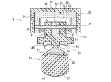
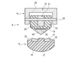
- FIG. 2 is a view schematically showing a part of the configuration of the end effector according to the first embodiment in a cross section passing through a longitudinal axis.
- FIG. 3 is a view schematically showing the configuration of the end effector according to the first embodiment in a cross section intersecting the longitudinal axis.
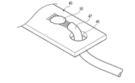
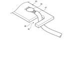
- FIG. 4 is a perspective view schematically showing a connection portion between the second electrode and the electrical wiring according to the first embodiment.
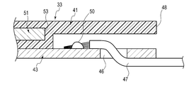
- FIG. 5 is a view schematically showing, in a cross section intersecting the width direction, the connection portion between the second electrode and the electrical wiring according to the first embodiment.
- FIG. 6 is a perspective view schematically showing a connection portion between a second electrode and an electrical wiring according to a modification of the first embodiment.
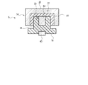
- FIG. 7 is a view schematically showing, in a cross section intersecting the longitudinal axis, the connection structure between the shaft and the second grip piece according to the first embodiment.
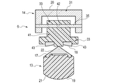
- FIG. 8 is a view schematically showing a configuration of an end effector according to a first modified example of the first embodiment in a cross section intersecting a longitudinal axis.
- FIG. 9 is a view schematically showing a configuration of a second gripping piece of an end effector according to a second modified example of the first embodiment in a cross section intersecting with the width direction.
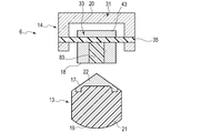
- FIG. 10 is a view schematically showing a configuration of an end effector according to a third modified example of the first embodiment in a cross section intersecting the longitudinal axis.
- FIG. 11 is a view schematically showing the configuration of the end effector according to the first reference example in a cross section intersecting the longitudinal axis.
- FIG. 12 is a view schematically showing the configuration of the end effector according to the second reference example in a cross section intersecting the longitudinal axis.
- FIG. 1 is a view showing a treatment tool 1 which is a medical device of the present embodiment.
- the treatment instrument 1 includes a holdable housing 4 and a cylindrical shaft 5 connected to the housing 4.
- One end of a cable 7 is connected to the housing 4.
- the other end of the cable 7 is detachably connected to the power supply 3.
- the shaft 5 defines a longitudinal axis C.
- the direction along the longitudinal axis C is taken as the longitudinal direction.
- One side in the longitudinal direction is the distal end side (arrow C1 side in FIG. 1), and the opposite side to the distal end side is the proximal end side (arrow C2 side in FIG. 1).
- the shaft 5 is extended along the longitudinal axis C from the proximal end side to the distal end side, and is connected to the distal end side of the housing 4.
- An end effector 6 is provided at the tip of the shaft 5.
- the end effector 6 comprises a first gripping piece 13 and a second gripping piece 14. Between the first grip piece 13 and the second grip piece 14 can be opened and closed.
- the first gripping piece 13 is fixed to the shaft 5, and the second gripping piece 14 is rotatably attached to the shaft 5 with respect to the first gripping piece 13.
- both the first gripping piece 13 and the second gripping piece 14 are rotatably attached to the shaft 5.
- the first gripping piece 13 includes a treatment surface (facing surface) 17 opposed to the second gripping piece 14 and a back surface 19 facing the opposite side to the treatment surface 17.
- the second gripping piece 14 includes a treatment surface (facing surface) 18 facing the treatment surface 17 of the first gripping piece 13 and a back surface 20 facing the treatment surface 18.
- the open / close direction of the end effector 6 intersects (is substantially perpendicular to) the longitudinal axis C.
- the side in which the second gripping piece 14 opens with respect to the first gripping piece 13 is the opening direction (arrow Y1) of the second gripping piece 14, and the second gripping piece 14 is The side closed with respect to the first gripping piece 13 is taken as the closing direction (arrow Y2) of the second gripping piece 14.
- the width direction of the end effector 6 is a direction intersecting (vertically or substantially perpendicular) to the longitudinal axis C and intersecting (vertically or substantially perpendicular) to the opening / closing direction of the end effector 6 .
- the housing 4 includes a housing body 15 and a grip (fixed handle) 11.
- the housing body 15 extends along the longitudinal axis C.
- the grip 11 extends from the housing body 15 in a direction away from the longitudinal axis C.
- the shaft 5 is connected to the housing body 15 from the tip side.
- a movable handle 12 is rotatably attached to the housing body 15.
- the movable handle 12 is located on the side where the grip 11 is located with respect to the longitudinal axis C, and is located on the distal side with respect to the grip 11 in the present embodiment.
- the movable handle 12 is pivoted relative to the housing body 15 so that the movable handle 12 opens or closes relative to the grip 11.
- an operation for opening or closing the end effector 6 as described above is input at the movable handle 12 which is an open / close operation input unit.
- the movable handle 12 and the second grip piece 14 are connected via a movable member 16 which extends along the longitudinal axis C inside the shaft 5.
- the movable member 16 moves along the longitudinal axis C relative to the shaft 5 and the housing 4 by opening or closing the movable handle 12 which is an open / close operation input unit with respect to the grip 11, and the second grip piece 14 is a shaft 5 and the first gripping piece 13 are pivoted. Thereby, the holding pieces 13 and 14 are opened or closed.
- the treatment target is held between the holding pieces 13 and 14 by closing between the holding pieces 13 and 14.
- the movable handle 12 is proximal to the grip 11. In another embodiment, the movable handle 12 is located on the opposite side of the longitudinal axis C to the side where the grip 11 is located, and intersects the longitudinal axis C in the opening operation and the closing operation ( Vertically or nearly vertically).
- an operating member such as a rotation knob is attached to the housing 4.
- the shaft 5 and the end effector 6 together rotate with respect to the housing 4 about the longitudinal axis C.
- the power supply device 3 includes a high frequency power supply and a thermal power supply.
- the high frequency power supply includes a waveform generator, a conversion circuit, a transformer, and the like, and converts power from a battery power supply or an outlet power supply to high frequency power. Further, as described later, each of the first grip piece 13 and the second grip piece 14 is at least partially formed of a conductive material.
- the high frequency power source is electrically connected to each of the first gripping piece 13 and the second gripping piece 14 through an electrical path provided through the inside of the cable 7, the inside of the housing 4 and the inside of the shaft 5. Ru.
- the high frequency power supply outputs the converted high frequency power through the aforementioned electric path, and supplies the first holding piece 13 and the second holding piece 14 with high frequency power as electric energy.
- the thermal power supply includes a conversion circuit, a transformer, and the like, and converts power from a battery power supply or a wall outlet power supply into direct current power or alternating current power. Further, a heat source (heating element) 25 described later is provided on at least one of the first grip piece 13 and the second grip piece 14. The thermal power source is electrically connected to the heat source 25 via an electrical path provided through the interior of the cable 7, the interior of the housing 4 and the interior of the shaft 5. The thermal power supply outputs the converted power through the above-described electric path to supply the heat source 25 with electrical energy.
- the housing main body 15 of the housing 4 is provided with an operation button 10 which is an energy operation input unit.
- an operation button 10 which is an energy operation input unit.
- electric energy is supplied to the end effector 6 from each of the high frequency power source and the thermal power source and held. High frequency current and heat are given to treatment subject as treatment energy.
- a foot switch electrically connected to the power supply 3 is provided separately from the treatment instrument 1 instead of or in addition to the operation button 10.
- the housing 4 is provided with a plurality of operation buttons 10.
- a certain operation button 10 for example, only the high frequency current is given as treatment energy to the treatment object.
- a high frequency current and heat are given to the treatment target as treatment energy.
- FIG. 2 is a view showing the tip of the shaft 5 and the end effector 6.
- FIG. 2 is a view showing a part in a cross section (vertical or substantially perpendicular) passing through the longitudinal axis C and intersecting with the width direction of the end effector 6.
- FIG. 3 is a view showing a closed state between the gripping pieces 13 and 14 in a cross section (vertical or substantially vertical) intersecting the longitudinal axis C.
- the first gripping piece 13 includes a support 21 and a conductive member (blade) 22.
- Each of the support 21 and the conductive member 22 extends in the direction along the longitudinal axis C from the proximal end to the distal end of the gripping piece 13.
- the support 21 is fixed to the shaft 5.
- the support 21 is formed of, for example, a material having electrical insulation and low thermal conductivity.
- the support 21 is formed of, for example, a resin.
- the support body 21 may be formed by insert-molding resin to a metal core material.
- the conductive member 22 is attached to the support 21 from the side of the grip piece 14.
- the conductive member 22 has conductivity.
- the conductive member 22 is formed of, for example, a material having high thermal conductivity, such as a copper alloy or an aluminum alloy.
- the conductive member 22 forms at least a part of the treatment surface 17. In the present embodiment, the treatment surface 17 is formed to be closer to the gripping piece 14 toward the center in the width direction.
- the conductive member 22 is connected to one end of an electrical path formed of an electrical wiring or the like. This electrical path extends through the interior of the shaft 5, the interior of the housing 4 and the interior of the cable 7, and the other end is connected to the high frequency power supply of the power supply 3. Thereby, the conductive member 22 and the high frequency power source are electrically connected, and high frequency power can be supplied from the high frequency power source to the conductive member 22 as electric energy.
- the conductive member 22 functions as a first electrode by being supplied with electrical energy.
- the first grip piece 13 includes a heat source 25.
- the heat source 25 is attached to the conductive member 22 from the side opposite to the treatment surface 17.
- the heat source 25 is provided in a range from the proximal end to the distal end of the gripping piece 13 in the longitudinal direction.
- the heat source 25 is a heating wire attached to the conductive member 22 or a heating pattern printed on the conductive member 22 or the like, and is formed of, for example, a nichrome alloy or a stainless steel alloy.
- the heat source 25 is electrically isolated from the conductive member 22.
- the heat source 25 is connected to one end of an electrical path formed of an electrical wiring or the like. This electrical path extends through the interior of the shaft 5, the interior of the housing 4 and the interior of the cable 7, and the other end is connected to the thermal power supply of the power supply 3. As a result, the heat source 25 and the heat source are electrically connected, and electrical energy can be supplied from the heat source to the heat source 25.
- the supply of electric energy from the heat source to the heat source 25 generates heat in the heat source 25.
- the heat generated by the heat source 25 is transmitted to the conductive member 22 and applied as treatment energy from the treatment surface 17 to the treatment target held between the holding pieces 13 and 14.
- the second grip piece 14 includes a jaw (support) 31 and a swinging portion 33.
- the jaws 31 and the swinging portion 33 extend from the distal end of the gripping piece 14 to the proximal end along the extending direction of the gripping piece 14.
- the swinging portion 33 is swingable with respect to the jaws 31.
- the jaws 31 extend along the longitudinal axis C in a state where the gripping piece 14 is closed with respect to the gripping piece 13. That is, in the state where the gripping piece 14 is closed with respect to the gripping piece 13, the extending direction of the jaws 31 is parallel or substantially parallel to the longitudinal axis C.
- the jaw 31 has a U-shape in which a cross-sectional shape intersecting (perpendicularly or substantially perpendicular) to the extending direction is open toward the gripping piece 13.
- the jaws 31 also have an inward facing surface 32.
- the inward facing surface 32 faces away from the back surface 20.
- the jaws 31 are preferably formed of, for example, a metal such as stainless steel, but may be formed of a resin or the like.
- a cover 38 is attached to the jaws 31.
- the cover 38 is in close contact with the jaws 31 from the rear surface 20 side.
- the cover 38 is formed of a material having a thermal conductivity smaller than that of the jaws 31.
- the cover 38 is formed of, for example, a resin.
- the cover 38 forms the back surface 20 of the gripping piece 14. The cover 38 may not be provided.
- the swinging portion 33 is attached to the jaw 31 from the side of the gripping piece 13.
- the swinging portion 33 is attached to the jaw 31 via the swing pin 35.
- the swing pin 35 is provided at the central portion of the gripping piece 14 in the extending direction of the gripping piece 14 and extends along the width direction.
- the swing pin 35 is made of, for example, metal.
- the rocking portion 33 is rockable with respect to the jaw 31 with the rocking pin 35 as a rocking shaft.
- the swinging portion 33 forms the treatment surface 18 of the gripping piece 14.
- the swinging portion 33 has a back surface 34.
- the back surface 34 faces away from the treatment surface 18.
- the back surface 34 of the rocking portion 33 is opposed to the inward facing surface 32 of the jaw 31.
- the swinging portion 33 includes an electrode holder 41.
- the electrode holder 41 is extended from the tip end of the jaw 31 to the base end along the extension direction of the grip piece 14.
- the electrode holder 41 is formed of a material that has electrical insulation and low thermal conductivity.
- the electrode holder 41 is formed of, for example, a resin.
- the jaws 31 are provided with insertion holes 37.
- the insertion hole 37 is formed in the jaw 31 along the width direction.
- the insertion holes 37 are formed in both side walls of the jaw 31 in the width direction, and penetrate the side wall of the jaw 31.
- the electrode holder 41 is provided with an insertion hole 42.
- the insertion hole 42 is formed along the width direction in the electrode holder 41.
- the swing pin 35 is inserted through the insertion hole 37 of the jaw 31 and the insertion hole 42 of the electrode holder 41.
- the electrode holder 41 is attached to the jaw 31 by inserting the rocking pin 35 into the insertion holes 37 and 42.
- a conductive member (second electrode) 43 is attached to the electrode holder 41.
- the conductive member 43 is attached to the electrode holder 41 from the side of the gripping piece 13.
- the conductive member 43 is extended along the extending direction of the gripping piece 14 and extends over the range from the distal end of the jaw 31 to the proximal end.
- the conductive member 43 forms a part of the treatment surface 17.
- the conductive member 43 is conductive.
- the conductive member 43 is formed of, for example, a metal such as stainless steel.
- the conductive member 43 is electrically insulated from the jaw 31 and the swing pin 35 via the electrode holder 41.
- the conductive member 43 has a thermal conductivity larger than that of the electrode holder 41. Therefore, the electrode holder 41 has a thermal conductivity smaller than that of the conductive member 43.
- the electrode holder 41 includes an abutting portion 45.
- the contact portion 45 is provided at the central position of the grip piece 14 in the width direction.
- the contact portion 45 protrudes from the conductive member 43 toward the gripping piece 13 side.
- the contact portion 45 forms a central portion of the treatment surface 17 in the width direction.
- the contact portion 45 of the electrode holder 41 abuts on the treatment surface 17 of the gripping piece 13 in a state where the gap between the gripping pieces 13 and 14 is closed. In this state, a gap is formed between the conductive member 22 and the conductive member 43, and the conductive member 43 does not contact the conductive member 22. Therefore, in a state where the conductive member 22 and the conductive member 43 function as electrodes, a short circuit in an electric circuit in which high frequency power is output from the power supply 3 to the conductive member 22 and the conductive member 43 is effectively prevented.
- An aggregate 51 is attached to the electrode holder 41.
- the aggregate 51 is extended along the extending direction of the grip piece 14 and extends over the range from the tip end of the jaw 31 to the base end.
- the aggregate 51 is disposed inside the electrode holder 41.
- the electrode holder 41 is in close contact with the aggregate 51 in the width direction from the outside. Therefore, the electrode holder 41 covers at least a part of the aggregate 51.
- the aggregate 51 is separated from the conductive member 43 via the electrode holder 41. Therefore, the aggregate 51 is electrically insulated from the conductive member 43 via the electrode holder 41.
- the aggregate 51 is formed of a material having a bending strength greater than that of the electrode holder 41.
- the electrode holder 41 is formed, for example, of metal or ceramic.
- an insertion hole 52 is provided in the aggregate 51.
- the insertion hole 52 penetrates the aggregate 51 in the width direction.
- the swing pin 35 is inserted into the insertion hole 52. That is, the swing pin 35 penetrates the aggregate 51.
- the aggregate 51 is supported by the jaw 31 together with the electrode holder 41 via the swing pin 35.
- the aggregate 51 is pivotable relative to the jaws 31 together with the electrode holder 41.
- the electrode holder 41 includes projections provided on both sides of the aggregate 51 in the width direction, and the projections project toward the jaws 31 in the electrode holder 41.
- the penetration hole 42 is formed in each of arium
- the aggregate 51 includes the protrusions 54 and 55.
- the protrusions 54 and 55 protrude from the back surface 34 of the swinging portion 33 toward the inward facing surface 32 of the jaw 31.
- the projecting portion 54 is provided on the proximal side of the swinging shaft (35) in the extending direction of the gripping piece 14.
- the protrusion 54 abuts on the inward facing surface 32 of the jaw 31 when a portion closer to the jaw 31 than the rocking shaft (35) in the rocking portion 33 is.
- the projecting portion 55 is located on the tip side of the swinging shaft (35) in the extending direction of the gripping piece 14.
- the protrusion 55 abuts on the inward facing surface 32 of the jaw 31 when the portion on the tip end side of the swinging shaft 33 approaches the jaw 31 in the swinging portion 33.
- the aggregate 51 is exposed from the electrode holder 41 at the portion of the swinging portion 33 that abuts against the jaw 31 by swinging with respect to the jaw 31. Therefore, when the swinging portion 33 and the jaw 31 abut on each other, the aggregate 51 comes in contact with the jaw 31. That is, in the swinging portion 33, the contact portion with the jaw 31 is formed by the aggregate 51.
- FIG. 4 and FIG. 5 are views showing the base end of the rocking portion 33.
- FIG. 4 is a perspective view
- FIG. 5 is a view showing a cross section perpendicular or substantially perpendicular to the width direction.
- one end of an electrical wiring (lead wire) 47 is connected to the proximal end of the conductive member 43.
- the electrical wiring 47 is extended through the inside of the shaft 5, the inside of the housing 4 and the inside of the cable 7, and the other end is electrically connected to the high frequency power supply of the power supply 3.
- the conductive member 43 and the high frequency power source are electrically connected, and high frequency power can be supplied from the high frequency power source to the conductive member 43 as electrical energy.
- the conductive member 43 functions as a second electrode by being supplied with electrical energy.
- An insertion hole 46 is formed at the proximal end of the conductive member 43.
- the insertion hole 46 penetrates the conductive member 43 from the treatment surface 18 side toward the back surface 20 side.
- the insertion hole 46 is located in the vicinity of the connection portion 50 between the electrical wiring 47 and the conductive member 43.
- the electrical wiring 47 is extended from the inside of the shaft 5 to the tip side and is inserted into the insertion hole 46.
- the power supply device 3 outputs high frequency power as electric energy from the high frequency power source based on the operation of the operation button 10.
- the output high frequency power is supplied to the conductive member 22 of the gripping piece 13 through the above-described electrical path, and is also supplied to the conductive member 43 of the gripping piece 14 through the above-described electrical path.
- the conductive member 22 and the conductive member 43 function as electrodes having different potentials with respect to each other.
- the conductive member 22 and the conductive member 43 function as an electrode in a state in which the treatment target is held between the holding pieces 13 and 14 so that a high frequency current flows between the conductive member 22 and the conductive member 43 through the treatment target.
- a high frequency current is applied to the subject as treatment energy.
- the electrode holder 41 is provided over a range from the aggregate 51 to the proximal end side in the extending direction of the gripping piece 14. Therefore, the proximal end 48 of the electrode holder 41 is positioned more proximal than the proximal end 53 of the aggregate 51. The proximal end 48 of the electrode holder 41 is located on the distal side of the connecting portion 50 between the conductive member 43 and the electrical wiring 47.
- the aggregate 51 is extended in the extending direction of the gripping piece 14 to a position closer to the tip end than the connection portion 50 between the conductive member 43 and the electric wiring 47. Therefore, the proximal end 53 of the aggregate 51 is positioned more distal than the connecting portion 50.
- the insertion hole 46 is provided with the opening part 49 opened toward one side of the width direction. In this case, when connecting the electrical wire 47 to the conductive member 43, the electrical wire 47 can be inserted into the insertion hole 46 through the opening 49.
- FIG. 7 is a view showing a connecting structure of the shaft 5 and the second grip piece 14.
- a cross section (substantially perpendicular) intersecting the longitudinal axis C has a U shape opened toward the second grip piece 14 side.
- a cross section (substantially perpendicular) of the proximal end portion of the jaw 31 of the second gripping piece 14 in the extending direction of the gripping piece 14 is opened toward the shaft 5 side (the first gripping piece 13 side) It becomes U-shaped.
- the second gripping pieces 14 are disposed on both outer sides of the shaft 5 in the width direction. At this time, the surface of the shaft 5 facing outward in the width direction and the surface of the second grip piece 14 facing inward in the width direction face each other in a separated state.
- An engagement hole 58 is formed at the tip of the shaft 5.
- the engagement hole 58 is formed at the tip of the shaft 5 along the width direction.
- the engagement holes 58 are provided on both side surfaces in the width direction at the tip end portion of the shaft 5 and penetrate the side surface of the shaft 5.
- An engagement hole 39 is formed at the proximal end of the jaw 31 of the second grip piece 14.
- the engagement holes 39 are formed in the jaws 31 along the width direction.
- the engagement holes 39 are provided on both side surfaces of the proximal end of the jaw 31 and penetrate the side surface of the jaw 31.
- the pivot pin 61 is inserted into the engagement hole 58 and the engagement hole 39.
- the pivot pin 61 is extended along the width direction, and is inserted into each of the engagement hole 58 and the engagement hole 39.
- the second grip piece 14 is pivotably attached to the tip of the shaft 5.
- a washer 63 is disposed between the shaft 5 and the second grip piece 14.
- the washer 63 is a ring-shaped thin metal plate and has thermal conductivity.
- the pivot pin 61 is inserted through the washer 63.
- the washer 63 is preferably disposed at a position not in contact with the pivot pin 61.
- the washer 63 is a spring washer having elasticity.
- the washer 63 is in contact with the shaft 5 and the second grip piece 14 respectively.
- the washer 63 is biased by the shaft 5 and the second grip piece 14 and can slide relative to the shaft 5 and the second grip piece 14 respectively.
- the washer 63 can transfer heat between the second gripping piece 14 and the shaft 5.
- the first grip piece 13 is supported by the shaft 5.
- the heat generated by the heat source 25 is transmitted to the shaft 5 via the first grip piece 13.
- the washer 63 is provided between the shaft 5 and the second grip piece 14 so that the first grip piece 13 and the second grip piece 14 can be interposed between the first grip piece 13 and the second grip piece 14 via the washer 63 and the shaft 5. Heat is transferred.
- the end effector 6 When performing treatment using the treatment tool 1, first, the end effector 6 is inserted into a body cavity such as the abdominal cavity. Then, a treatment target such as a blood vessel is disposed between the pair of grasping pieces 13 and 14, and the end effector 6 is closed. Thereby, the treatment target is gripped between the gripping pieces 13 and 14. At this time, the treatment target is gripped between the treatment surface 17 and the treatment surface 18 provided on the swinging portion 33.
- the swinging portion 33 can swing around the swing pin 35 with respect to the jaw 31.
- the grasping of the treatment object between the gripping pieces 13 and 14 is more efficient than in the case where the proximal end of the treatment surface 18 abuts on the treatment object
- the forces are nearly identical. That is, even when the position of the treatment surface 18 in contact with the treatment target in the extending direction of the gripping pieces 14 changes, the gripping force between the gripping pieces 13 and 14 is maintained substantially uniform.
- the operation input for supplying the electric energy from the power supply device 3 to the treatment tool 1 is performed, whereby the high frequency current and the heat source 25 are transmitted.
- the heat of at least one is applied as treatment energy to the treatment object grasped between the grasping pieces 13 and 14.
- electrical energy (high frequency power) is supplied to the conductive member 43 via the electrical wiring 47.
- the electrode holder 41 is provided to electrically insulate between the jaw 31 and the aggregate 51 and the conductive member 43 of the grip piece 14. Therefore, electrical energy (high frequency power) is supplied to the conductive member 43 without passing through the jaws 31. That is, the jaws 31 are electrically isolated from the electrical path that supplies the conductive member 43 with electrical energy (high frequency power). Therefore, even when electric energy (high frequency power) is supplied to the conductive member 43, the jaws 31 and the swing pin 35 are not supplied with electric energy (high frequency power). For this reason, heat generated in the jaws 31 is suppressed as compared to the case where the jaws 31 form a part of the electrical path.
- the electrode holder 41 is formed of a material having a low thermal conductivity. For this reason, it is suppressed that the heat which generate
- the aggregate 51 is provided in the swinging portion 33, and the aggregate 51 is extended along the extending direction of the grip piece 14. Further, the aggregate 51 is formed of a material having a high bending strength (tensile strength). For this reason, even when the electrode holder 41 is formed of a material having a low thermal conductivity, such as a resin, the decrease in the bending strength of the rocking portion 33 can be suppressed by providing the aggregate 51. Thereby, the transmission of heat to the jaws 31 can be suppressed, and the durability (strength resistance) of the rocking portion 33 can be maintained.
- the contact portion of the swinging portion 33 with the jaw 31 is formed by the aggregate 51. Therefore, even when the electrode holder 41 is formed of a material having a low thermal conductivity such as a resin, the durability (strength resistance) of the rocking portion 33 is further ensured.
- a cover 38 formed of a material having a low thermal conductivity is attached to the jaws 31.
- the back surface 20 of the gripping piece 14 is formed by the cover 38. For this reason, residual heat from the back surface 20 of the gripping piece 14 is prevented from affecting the treatment.
- the proximal end 53 of the aggregate 51 is disposed on the distal side with respect to the connection portion 50 between the conductive member 43 and the electrical wiring 47. As a result, the contact between the aggregate 51 and the electrical wiring 47 is prevented, and the workability when connecting the electrical wiring 47 to the conductive member 43 is improved.
- the electrical wiring 47 is directly connected to the conductive member 43, and the electrical energy (high frequency power) is supplied to the conductive member 43 without passing through the jaws 31.
- the jaws 31 rotate with respect to the shaft 5 and the swinging portion 33 swings with respect to the jaws 31.
- a force (peel force) to peel the electric wire 47 from the conductive member 43 acts on the connection portion 50. Since the strength of the electrical wiring 47 is particularly low at the connection portion 50, it is required to reduce the force acting on the electrical wiring 47 at the connection portion 50.
- the electrical wiring 47 is connected to the conductive member 43 in a state of being inserted into the insertion hole 46.
- the electrical wiring 47 is connected to the conductive member 43 at the connection portion 50 in a state of being fixed to the conductive member 43 once.
- a washer 63 is provided between the shaft 5 and the second grip piece 14.
- the washer 63 is a spring washer and facilitates the sliding of the second grip piece 14 on the shaft 5. Further, by the washer 63 being provided, heat is transmitted between the first gripping piece 13 and the second gripping piece 14 via the washer 63 and the shaft 5.
- the residual heat of the first grip piece 13 due to the generation of heat in the heat source 25 is diffused to the second grip piece 14 via the washer 63 and the shaft 5.
- the residual heat (heat storage amount) of the first gripping piece 13 is transmitted to the second gripping piece 14, whereby the residual heat of the first gripping piece 13 is reduced.
- the residual heat is made uniform in the end effector 6, whereby the rate of reduction of the residual heat in the end effector 6 is improved.
- the swing pin 35 and the aggregate 51 are integrally formed.
- the aggregate 51 includes a protrusion that protrudes outward in the width direction, and the protrusion functions as the swing pin 35.
- the swinging portion 33 is attached to the cover 38 via the swing pin 35.
- an insertion hole through which the rocking pin 35 is inserted is formed in the cover 38, and the rocking pin 35 is inserted in the cover 38 and the rocking portion 33.
- the swinging portion 33 is supported on the inside of the jaw 31 so as to be able to swing relative to the cover 38.
- ultrasonic vibration is used as the treatment energy.
- an ultrasonic transducer is provided inside the housing body 15, and the ultrasonic transducer is electrically connected to the power supply device 3.
- a vibration transfer member (rod member) is connected to the tip of the ultrasonic transducer.
- the vibration transmitting member extends along the longitudinal axis C through the inside of the housing 4 and the inside of the shaft 5 and protrudes from the tip of the shaft 5 toward the tip side.
- the 1st holding piece 13 is formed of the protrusion part to the front end side from the shaft 5 of a vibration transmission member.
- the end effector 6 is provided with a cutter (cold cutter).
- a groove is formed on each of the treatment surface 17 of the first gripping piece 13 and the treatment surface 18 of the second gripping piece 14.
- the groove is provided at a central position in the width direction in each of the treatment surfaces 17 and 18, and is extended along the longitudinal direction (the extending direction of the gripping piece 14). Then, the cutter is inserted from the proximal end side into the above-mentioned groove in a state in which the treatment object is held between the holding pieces 13 and 14, and the held treatment object is cut.
- FIG. 8 is a diagram showing a first modification.
- the heat source 25 may be provided to the second grip piece 14.
- the heat source 25 is attached to the conductive member 43 from the side opposite to the treatment surface 18.
- the heat generated by the heat source 25 is transferred to the conductive member 43 and applied from the treatment surface 18 to the treatment target.
- FIG. 9 is a diagram showing a second modification.
- a sliding groove 71 is provided on the inward facing surface 32 of the jaw 31, and a sliding projection 72 is provided on the back surface 34 of the swinging portion 33.
- the sliding groove 71 is a groove recessed from the inward surface 32 of the jaw 31 toward the back surface 20, and is formed in an arc shape in a cross section (vertical or substantially vertical) intersecting in the width direction.
- the sliding protrusion 72 protrudes from the back surface 34 of the swinging portion 33 toward the back surface 20, and is formed in an arc shape in a cross section (vertical or substantially vertical) intersecting in the width direction.
- the sliding protrusion 72 of the swinging portion 33 is engaged with the sliding groove 71 of the jaw 31.
- An insertion hole 73 is formed in each of the jaws 31 and the swinging portion 33.
- the insertion holes 73 pass through the side walls of the jaws 31 or the swinging portion 33 in the width direction.
- the retaining pin 74 is inserted into the insertion hole 73.
- the retaining pin 74 is extended along the width direction.
- the insertion hole 73 is formed larger than the retaining pin 74.
- the swinging portion 33 is supported by the jaws 31 by inserting the retaining pins 74 into the insertion holes 73. As a result, it is possible to prevent the swinging portion 33 from coming off from the jaws 31, that is, to drop it out. Further, in a state where the sliding protrusion 72 of the swinging portion 33 is engaged with the sliding groove 71 of the jaw 31, the sliding protrusion 72 slides against the sliding groove 71, whereby the swinging portion 33 becomes a jaw. Swing against 31
- FIG. 10 is a view showing a third modification.
- a heat insulating material 81 is provided between the swinging portion 33 and the jaws 31.
- the heat insulator 81 has low thermal conductivity and has elasticity.
- a soft material such as rubber is used for the heat insulator 81.
- the swinging portion 33 is supported by the heat insulating material 81 so as to be supported inside the jaws 31. Since the heat insulating material 81 has elasticity, the swinging portion 33 can swing relative to the jaws 31. In addition, the heat insulating material 81 is disposed between the swinging portion 33 and the jaws 31 to further suppress the transfer of heat from the conductive member 43 to the jaws 31.
- FIG. 11 is a diagram showing a first reference example.
- the swinging portion 33 includes an electrode holder 41 and a conductive member 43.
- the electrode holder 41 is formed of a material having a low thermal conductivity, such as a resin. Further, one end of the electrical wiring 47 is connected to the base end of the conductive member 43.
- the electrical energy is supplied to the conductive member 43 without passing through the jaws 31, whereby the generation of heat in the jaws 31 is suppressed.
- the electrode holder 41 is formed of a material having a low thermal conductivity, the transfer of heat from the conductive member 43 to the jaws 31 is suppressed.
- FIG. 12 is a diagram showing a second reference example.
- the swinging portion 33 includes a conductive member 43 acting as a second electrode, and an insulating member 83 provided inside the conductive member 43.
- the insulating member 83 forms a portion on the treatment surface 18 that abuts on the treatment surface 17 in a state where the grip pieces 13 and 14 are closed.
- the swing pin 35 has low thermal conductivity and has electrical insulation.
- the swing pin 35 is formed of resin.
- the swing pin 35 includes a metal pin and a resin tube covering the outer surface of the pin.
- the swing pin 35 is formed by applying a thermal barrier coating to the outer surface of the metal pin.
- the heat conductivity of the swing pin 35 is formed low, so that the transfer of heat from the conductive member 43 of the swing portion 33 to the jaw 31 is suppressed.
- the medical device (1) comprises a first electrode (22), a jaw (31) opening and closing the first electrode (22), and a treatment surface (18) facing the first electrode (22).
- the present invention is not limited to the above embodiment, and can be variously modified in the implementation stage without departing from the scope of the invention.
- the embodiments may be implemented in combination as appropriate as possible, in which case the combined effect is obtained.
- the above embodiments include inventions of various stages, and various inventions can be extracted by an appropriate combination of a plurality of disclosed configuration requirements.
Abstract
This medical device is provided with: a first electrode; a jaw which opens and closes with respect to the first electrode; a second electrode which forms a treatment surface that faces the first electrode; an electrode holder which is mounted to the second electrode from the side opposite to the treatment surface so as to be oscillatable with respect to the jaw, and which has a thermal conductivity lower than that of the second electrode; and an aggregate which is provided to the electrode holder, is electrically insulated from the second electrode, and has a flexural strength greater than that of the electrode holder.
Description
本発明は、処置エネルギーを用いて処置対象を処置する医療機器に関する。
The present invention relates to a medical device that treats a treatment target using treatment energy.
US2017/0000556A1には、一対の把持片の間で生体組織等の処置対象を把持し、高周波電流等の処置エネルギーを用いて把持された処置対象を処置する医療機器が開示されている。この医療機器では、一対の把持片は、互いに対して対向する一対の把持面を備える。把持面のそれぞれには電極が設けられ、電極のそれぞれには電気エネルギー(高周波電力)供給される。電極のそれぞれに電気エネルギー(高周波電力)が供給されることにより、処置対象を通して把持片の間に高周波電流が流れ、処置対象が処置される。
US 2017/0000556 A1 discloses a medical device that holds a treatment target such as a living tissue between a pair of holding pieces and treats a treatment target held using treatment energy such as a high frequency current. In this medical device, the pair of gripping pieces includes a pair of gripping surfaces facing each other. An electrode is provided on each of the gripping surfaces, and each of the electrodes is supplied with electrical energy (high frequency power). By supplying electric energy (high frequency power) to each of the electrodes, a high frequency current flows between the grasping pieces through the treatment object to treat the treatment object.
US2017/0000556A1のような医療機器では、処置対象に付与される把持力を均一化するために、把持片の一方にワイパー構造が設けられることがある。この場合、ワイパー構造が設けられる把持片は、ジョーと、揺動部とを備える。揺動部は、ピンを介して、ジョーに対して揺動可能に取付けられる。揺動部には、電極が設けられる。電極には、ジョー及びピンを介して電気エネルギー(高周波電力)が供給される。このような医療機器を用いた処置では、ジョーが、電極に電気エネルギーを供給する電気経路の一部を形成し、ジョーに熱が生じやすい。また、電極で生じた熱が、ジョーに伝達されやすい。
In a medical device such as US2017 / 0000556A1, in order to equalize the gripping force applied to the treatment object, one of the gripping pieces may be provided with a wiper structure. In this case, the gripping piece provided with the wiper structure comprises a jaw and a swinging part. The swinging portion is swingably attached to the jaw via a pin. The swinging portion is provided with an electrode. The electrodes are supplied with electrical energy (high frequency power) via the jaws and pins. In procedures using such medical devices, the jaws form part of an electrical pathway that supplies electrical energy to the electrodes, and the jaws are prone to heat. Also, the heat generated at the electrode is easily transmitted to the jaws.
本発明は前記課題に着目してなされたものであり、その目的とするところは、ジョーでの熱の発生及びジョーへの熱の伝達を抑制できる医療機器を提供することにある。
The present invention has been made focusing on the above-mentioned problems, and an object of the present invention is to provide a medical device capable of suppressing the generation of heat in the jaws and the transfer of heat to the jaws.
前記目的を達成するため、本発明のある態様の医療機器は、第1の電極と、前記第1の電極に対して開閉するジョーと、前記第1の電極に対向する処置面を形成する第2の電極と、前記ジョーに対して揺動可能に取付けられ、前記第2の電極に前記処置面とは反対側から取付けられ、前記第2の電極よりも熱伝導率が低い、電極ホルダと、前記電極ホルダに設けられ、前記第2の電極に対して電気的に絶縁され、前記電極ホルダよりも曲げ強度が大きい骨材と、を備える。
In order to achieve the above object, a medical device according to an aspect of the present invention includes a first electrode, a jaw opening and closing with respect to the first electrode, and a treatment surface facing the first electrode. An electrode holder mounted on the second electrode so as to be swingable relative to the jaw, and attached to the second electrode from the side opposite to the treatment surface, and having a lower thermal conductivity than the second electrode; And an aggregate provided on the electrode holder, electrically insulated from the second electrode, and having a bending strength higher than that of the electrode holder.
(第1の実施形態)
本発明の第1の実施形態について、図1乃至図7を参照して説明する。 First Embodiment
A first embodiment of the present invention will be described with reference to FIGS. 1 to 7.
本発明の第1の実施形態について、図1乃至図7を参照して説明する。 First Embodiment
A first embodiment of the present invention will be described with reference to FIGS. 1 to 7.
図1は、本実施形態の医療機器である処置具1を示す図である。図1に示すように、処置具1は、保持可能なハウジング4と、ハウジング4に連結される筒状のシャフト5と、を備える。ハウジング4には、ケーブル7の一端が接続されている。ケーブル7の他端は、電源装置3に着脱可能に接続される。
FIG. 1 is a view showing a treatment tool 1 which is a medical device of the present embodiment. As shown in FIG. 1, the treatment instrument 1 includes a holdable housing 4 and a cylindrical shaft 5 connected to the housing 4. One end of a cable 7 is connected to the housing 4. The other end of the cable 7 is detachably connected to the power supply 3.
シャフト5は、長手軸Cを規定する。ここで、長手軸Cに沿う方向を長手方向とする。長手方向の一方側を先端側(図1の矢印C1側)とし、先端側とは反対側を基端側(図1の矢印C2側)とする。シャフト5は、基端側から先端側へ長手軸Cに沿って延設され、ハウジング4の先端側に連結されている。
The shaft 5 defines a longitudinal axis C. Here, the direction along the longitudinal axis C is taken as the longitudinal direction. One side in the longitudinal direction is the distal end side (arrow C1 side in FIG. 1), and the opposite side to the distal end side is the proximal end side (arrow C2 side in FIG. 1). The shaft 5 is extended along the longitudinal axis C from the proximal end side to the distal end side, and is connected to the distal end side of the housing 4.
シャフト5の先端部には、エンドエフェクタ6が設けられている。エンドエフェクタ6は、第1の把持片13と第2の把持片14とを備える。第1の把持片13と第2の把持片14との間は、開閉可能である。本実施形態では、第1の把持片13は、シャフト5に固定され、第2の把持片14は、第1の把持片13に対して回動可能にシャフト5に取付けられている。ある実施例では、第1の把持片13及び第2の把持片14の両方が、シャフト5に対して回転可能に取付けられる。
An end effector 6 is provided at the tip of the shaft 5. The end effector 6 comprises a first gripping piece 13 and a second gripping piece 14. Between the first grip piece 13 and the second grip piece 14 can be opened and closed. In the present embodiment, the first gripping piece 13 is fixed to the shaft 5, and the second gripping piece 14 is rotatably attached to the shaft 5 with respect to the first gripping piece 13. In one embodiment, both the first gripping piece 13 and the second gripping piece 14 are rotatably attached to the shaft 5.
第1の把持片13は、第2の把持片14に対して対向する処置面(対向面)17と、処置面17とは反対側を向く背面19とを備える。第2の把持片14は、第1の把持片13の処置面17に対して対向する処置面(対向面)18と、処置面18とは反対側を向く背面20とを備える。
The first gripping piece 13 includes a treatment surface (facing surface) 17 opposed to the second gripping piece 14 and a back surface 19 facing the opposite side to the treatment surface 17. The second gripping piece 14 includes a treatment surface (facing surface) 18 facing the treatment surface 17 of the first gripping piece 13 and a back surface 20 facing the treatment surface 18.
エンドエフェクタ6の開閉方向は、長手軸Cに対して交差する(略垂直となる)。エンドエフェクタ6の開閉方向のうち、第2の把持片14が第1の把持片13に対して開く側を第2の把持片14の開方向(矢印Y1)とし、第2の把持片14が第1の把持片13に対して閉じる側を第2の把持片14の閉方向(矢印Y2)とする。ここで、長手軸Cに対して交差し(垂直又は略垂直で)、かつ、エンドエフェクタ6の開閉方向に対して交差する(垂直又は略垂直な)方向を、エンドエフェクタ6の幅方向とする。
The open / close direction of the end effector 6 intersects (is substantially perpendicular to) the longitudinal axis C. Of the opening and closing directions of the end effector 6, the side in which the second gripping piece 14 opens with respect to the first gripping piece 13 is the opening direction (arrow Y1) of the second gripping piece 14, and the second gripping piece 14 is The side closed with respect to the first gripping piece 13 is taken as the closing direction (arrow Y2) of the second gripping piece 14. Here, the width direction of the end effector 6 is a direction intersecting (vertically or substantially perpendicular) to the longitudinal axis C and intersecting (vertically or substantially perpendicular) to the opening / closing direction of the end effector 6 .
ハウジング4は、ハウジング本体15と、グリップ(固定ハンドル)11とを備える。ハウジング本体15は、長手軸Cに沿って延設されている。グリップ11は、長手軸Cから離れる側へ向かってハウジング本体15から延設されている。シャフト5は、ハウジング本体15に先端側から連結されている。
The housing 4 includes a housing body 15 and a grip (fixed handle) 11. The housing body 15 extends along the longitudinal axis C. The grip 11 extends from the housing body 15 in a direction away from the longitudinal axis C. The shaft 5 is connected to the housing body 15 from the tip side.
ハウジング本体15には、可動ハンドル12が回動可能に取付けられている。可動ハンドル12は、長手軸Cに対してグリップ11が位置する側に位置し、本実施形態ではグリップ11に対して先端側に位置している。可動ハンドル12がハウジング本体15に対して回動することにより、可動ハンドル12がグリップ11に対して開く又は閉じる。可動ハンドル12がグリップ11に対して開く又は閉じることにより、エンドエフェクタ6を前述のように開動作又は閉動作させる操作が、開閉操作入力部である可動ハンドル12において、入力される。
A movable handle 12 is rotatably attached to the housing body 15. The movable handle 12 is located on the side where the grip 11 is located with respect to the longitudinal axis C, and is located on the distal side with respect to the grip 11 in the present embodiment. The movable handle 12 is pivoted relative to the housing body 15 so that the movable handle 12 opens or closes relative to the grip 11. When the movable handle 12 opens or closes with respect to the grip 11, an operation for opening or closing the end effector 6 as described above is input at the movable handle 12 which is an open / close operation input unit.
可動ハンドル12と第2の把持片14との間は、シャフト5の内部に長手軸Cに沿って延設される可動部材16を介して、連結されている。開閉操作入力部である可動ハンドル12をグリップ11に対して開く又は閉じることにより、可動部材16がシャフト5及びハウジング4に対して長手軸Cに沿って移動し、第2の把持片14がシャフト5及び第1の把持片13に対して回動する。これにより、把持片13,14の間が開く又は閉じる。把持片13、14の間に処置対象が配置された状態で把持片13、14の間が閉じることにより、把持片13、14の間で処置対象が把持される。
The movable handle 12 and the second grip piece 14 are connected via a movable member 16 which extends along the longitudinal axis C inside the shaft 5. The movable member 16 moves along the longitudinal axis C relative to the shaft 5 and the housing 4 by opening or closing the movable handle 12 which is an open / close operation input unit with respect to the grip 11, and the second grip piece 14 is a shaft 5 and the first gripping piece 13 are pivoted. Thereby, the holding pieces 13 and 14 are opened or closed. When the treatment target is disposed between the holding pieces 13 and 14, the treatment target is held between the holding pieces 13 and 14 by closing between the holding pieces 13 and 14.
ある実施例では、可動ハンドル12は、グリップ11に対して基端側に位置する。また、別のある実施例では、可動ハンドル12は、長手軸Cに対してグリップ11が位置する側とは反対側に位置し、開動作及び閉動作において、長手軸Cに対して交差する(垂直又は略垂直な)方向に移動する。
In one embodiment, the movable handle 12 is proximal to the grip 11. In another embodiment, the movable handle 12 is located on the opposite side of the longitudinal axis C to the side where the grip 11 is located, and intersects the longitudinal axis C in the opening operation and the closing operation ( Vertically or nearly vertically).
また、ある実施例では、ハウジング4に回転ノブ等の操作部材(図示しない)が取付けられる。この場合、操作部材をハウジング4に対して長手軸Cの軸回りに回転することにより、シャフト5及びエンドエフェクタ6が一緒に、ハウジング4に対して長手軸Cの軸回りに回転する。
Further, in one embodiment, an operating member (not shown) such as a rotation knob is attached to the housing 4. In this case, by rotating the operation member with respect to the housing 4 about the longitudinal axis C, the shaft 5 and the end effector 6 together rotate with respect to the housing 4 about the longitudinal axis C.
電源装置3は、高周波電源と熱電源とを備える。高周波電源は、波形生成器、変換回路及び変圧器等を備え、バッテリー電源又はコンセント電源等からの電力を高周波電力に変換する。また、後述するように、第1の把持片13及び第2の把持片14のそれぞれは、少なくとも一部が導電材料によって形成される。高周波電源は、ケーブル7の内部、ハウジング4の内部及びシャフト5の内部を通って設けられる電気経路を介して、第1の把持片13及び第2の把持片14のそれぞれに電気的に接続される。高周波電源は、変換した高周波電力を前述の電気経路を通して出力し、第1の把持片13及び第2の把持片14に高周波電力を電気エネルギーとして供給する。
The power supply device 3 includes a high frequency power supply and a thermal power supply. The high frequency power supply includes a waveform generator, a conversion circuit, a transformer, and the like, and converts power from a battery power supply or an outlet power supply to high frequency power. Further, as described later, each of the first grip piece 13 and the second grip piece 14 is at least partially formed of a conductive material. The high frequency power source is electrically connected to each of the first gripping piece 13 and the second gripping piece 14 through an electrical path provided through the inside of the cable 7, the inside of the housing 4 and the inside of the shaft 5. Ru. The high frequency power supply outputs the converted high frequency power through the aforementioned electric path, and supplies the first holding piece 13 and the second holding piece 14 with high frequency power as electric energy.
熱電源は、変換回路及び変圧器等を備え、バッテリー電源又はコンセント電源等からの電力を直流電力又は交流電力に変換する。また、第1の把持片13及び第2の把持片14の少なくとも一方には、後述する熱源(発熱体)25が設けられる。熱電源は、ケーブル7の内部、ハウジング4の内部及びシャフト5の内部を通って設けられる電気経路を介して、熱源25に電気的に接続される。熱電源は、変換した電力を前述の電気経路を通して出力し、熱源25に電気エネルギーを供給する。
The thermal power supply includes a conversion circuit, a transformer, and the like, and converts power from a battery power supply or a wall outlet power supply into direct current power or alternating current power. Further, a heat source (heating element) 25 described later is provided on at least one of the first grip piece 13 and the second grip piece 14. The thermal power source is electrically connected to the heat source 25 via an electrical path provided through the interior of the cable 7, the interior of the housing 4 and the interior of the shaft 5. The thermal power supply outputs the converted power through the above-described electric path to supply the heat source 25 with electrical energy.
ハウジング4のハウジング本体15には、エネルギー操作入力部である操作ボタン10が設けられている。把持片13,14の間で処置対象が把持された状態で、操作ボタン10で操作が入力されることにより、高周波電源及び熱電源のそれぞれからエンドエフェクタ6に電気エネルギーが供給され、把持された処置対象に高周波電流及び熱が処置エネルギーとして付与される。なお、ある実施例では、操作ボタン10の代わりに、又は、操作ボタン10に加えて、電源装置3に電気的に接続されるフットスイッチが、処置具1とは別体に設けられる。
The housing main body 15 of the housing 4 is provided with an operation button 10 which is an energy operation input unit. In the state where the treatment object is held between the holding pieces 13 and 14, by inputting the operation with the operation button 10, electric energy is supplied to the end effector 6 from each of the high frequency power source and the thermal power source and held. High frequency current and heat are given to treatment subject as treatment energy. In one embodiment, a foot switch electrically connected to the power supply 3 is provided separately from the treatment instrument 1 instead of or in addition to the operation button 10.
また、ある実施例では、ハウジング4に複数の操作ボタン10が設けられる。処置対象が把持された状態で、ある操作ボタン10で操作が入力されることにより、例えば、処置対象に高周波電流のみが処置エネルギーとして付与される。処置対象が把持された状態で、別の操作ボタン10で操作が入力されることにより、例えば、処置対象に高周波電流と熱とが、処置エネルギーとして付与される。
Also, in one embodiment, the housing 4 is provided with a plurality of operation buttons 10. In the state where the treatment object is gripped, when an operation is inputted with a certain operation button 10, for example, only the high frequency current is given as treatment energy to the treatment object. In the state where the treatment target is gripped, when an operation is input by another operation button 10, for example, a high frequency current and heat are given to the treatment target as treatment energy.
図2は、シャフト5の先端部とエンドエフェクタ6を示す図である。図2は、長手軸Cを通り、かつ、エンドエフェクタ6の幅方向に対して交差する(垂直又は略垂直な)断面で一部を示す図である。図3は、把持片13、14の間が閉じた状態を、長手軸Cに交差する(垂直又は略垂直な)断面で示す図である。
FIG. 2 is a view showing the tip of the shaft 5 and the end effector 6. FIG. 2 is a view showing a part in a cross section (vertical or substantially perpendicular) passing through the longitudinal axis C and intersecting with the width direction of the end effector 6. FIG. 3 is a view showing a closed state between the gripping pieces 13 and 14 in a cross section (vertical or substantially vertical) intersecting the longitudinal axis C.
図2及び図3に示すように、第1の把持片13は、支持体21と、導電部材(ブレード)22と、を備える。支持体21及び導電部材22のそれぞれは、長手軸Cに沿う方向について把持片13の基端部から先端部までの範囲に渡って延設される。支持体21は、シャフト5に固定されている。支持体21は、例えば、電気的絶縁性を有し、熱伝導率が小さい材料から形成される。支持体21は、例えば、樹脂から形成される。また、支持体21は、金属の芯材に樹脂をインサート成形することにより、形成されてもよい。
As shown in FIGS. 2 and 3, the first gripping piece 13 includes a support 21 and a conductive member (blade) 22. Each of the support 21 and the conductive member 22 extends in the direction along the longitudinal axis C from the proximal end to the distal end of the gripping piece 13. The support 21 is fixed to the shaft 5. The support 21 is formed of, for example, a material having electrical insulation and low thermal conductivity. The support 21 is formed of, for example, a resin. Moreover, the support body 21 may be formed by insert-molding resin to a metal core material.
導電部材22は、把持片14側から支持体21に取付けられている。導電部材22は、導電性を有する。導電部材22は、例えば、銅合金又はアルミ合金等の熱伝導性が高い材料から形成される。導電部材22は、処置面17の少なくとも一部を形成する。本実施形態では、処置面17は、幅方向について中央に向かうにつれて把持片14側に向かう状態に形成されている。
The conductive member 22 is attached to the support 21 from the side of the grip piece 14. The conductive member 22 has conductivity. The conductive member 22 is formed of, for example, a material having high thermal conductivity, such as a copper alloy or an aluminum alloy. The conductive member 22 forms at least a part of the treatment surface 17. In the present embodiment, the treatment surface 17 is formed to be closer to the gripping piece 14 toward the center in the width direction.
導電部材22には、電気配線等から形成される電気経路の一端が接続される。この電気経路は、シャフト5の内部、ハウジング4の内部及びケーブル7の内部を通って延設され、他端が電源装置3の高周波電源に接続される。これにより、導電部材22と高周波電源とが電気的に接続され、高周波電源から導電部材22へ高周波電力を電気エネルギーとして供給可能になる。導電部材22は、電気エネルギーが供給されることにより、第1の電極として機能する。
The conductive member 22 is connected to one end of an electrical path formed of an electrical wiring or the like. This electrical path extends through the interior of the shaft 5, the interior of the housing 4 and the interior of the cable 7, and the other end is connected to the high frequency power supply of the power supply 3. Thereby, the conductive member 22 and the high frequency power source are electrically connected, and high frequency power can be supplied from the high frequency power source to the conductive member 22 as electric energy. The conductive member 22 functions as a first electrode by being supplied with electrical energy.
第1の把持片13は、熱源25を備える。熱源25は、導電部材22に処置面17とは反対側から取付けられている。熱源25は、長手方向について把持片13の基端部から先端部までの範囲に渡って設けられている。熱源25は、導電部材22に取付けられる発熱線又は導電部材22にプリントされる発熱パターン等であり、例えば、ニクロム合金又はステンレス合金等から形成される。熱源25は、導電部材22に対して電気的に絶縁されている。
The first grip piece 13 includes a heat source 25. The heat source 25 is attached to the conductive member 22 from the side opposite to the treatment surface 17. The heat source 25 is provided in a range from the proximal end to the distal end of the gripping piece 13 in the longitudinal direction. The heat source 25 is a heating wire attached to the conductive member 22 or a heating pattern printed on the conductive member 22 or the like, and is formed of, for example, a nichrome alloy or a stainless steel alloy. The heat source 25 is electrically isolated from the conductive member 22.
熱源25には、電気配線等から形成される電気経路の一端が接続される。この電気経路は、シャフト5の内部、ハウジング4の内部及びケーブル7の内部を通って延設され、他端が電源装置3の熱電源に接続される。これにより、熱源25と熱電源とが電気的に接続され、熱電源から熱源25に電気エネルギーを供給可能になる。熱電源から熱源25に電気エネルギーが供給されることにより、熱源25で熱が発生する。熱源25で発生した熱は、導電部材22に伝達され、把持片13、14の間で把持される処置対象に処置面17から処置エネルギーとして付与される。
The heat source 25 is connected to one end of an electrical path formed of an electrical wiring or the like. This electrical path extends through the interior of the shaft 5, the interior of the housing 4 and the interior of the cable 7, and the other end is connected to the thermal power supply of the power supply 3. As a result, the heat source 25 and the heat source are electrically connected, and electrical energy can be supplied from the heat source to the heat source 25. The supply of electric energy from the heat source to the heat source 25 generates heat in the heat source 25. The heat generated by the heat source 25 is transmitted to the conductive member 22 and applied as treatment energy from the treatment surface 17 to the treatment target held between the holding pieces 13 and 14.
第2の把持片14は、ジョー(支持体)31と、揺動部33とを備える。ジョー31及び揺動部33は、把持片14の延設方向に沿って把持片14の先端部から基端部に渡って延設されている。揺動部33は、ジョー31に対して揺動可能である。ジョー31は、把持片14が把持片13に対して閉じた状態において、長手軸Cに沿って延設される。すなわち、把持片14が把持片13に対して閉じた状態では、ジョー31の延設方向は、長手軸Cと平行又は略平行になる。ジョー31は、延設方向に対して交差する(垂直又は略垂直な)断面形状が、把持片13に向かって開口するU字形状となる。また、ジョー31は、内向面32を備える。内向面32は、背面20とは反対側を向いている。ジョー31は、例えば、ステンレス等の金属で形成されることが好ましいが、樹脂等で形成されてもよい。
The second grip piece 14 includes a jaw (support) 31 and a swinging portion 33. The jaws 31 and the swinging portion 33 extend from the distal end of the gripping piece 14 to the proximal end along the extending direction of the gripping piece 14. The swinging portion 33 is swingable with respect to the jaws 31. The jaws 31 extend along the longitudinal axis C in a state where the gripping piece 14 is closed with respect to the gripping piece 13. That is, in the state where the gripping piece 14 is closed with respect to the gripping piece 13, the extending direction of the jaws 31 is parallel or substantially parallel to the longitudinal axis C. The jaw 31 has a U-shape in which a cross-sectional shape intersecting (perpendicularly or substantially perpendicular) to the extending direction is open toward the gripping piece 13. The jaws 31 also have an inward facing surface 32. The inward facing surface 32 faces away from the back surface 20. The jaws 31 are preferably formed of, for example, a metal such as stainless steel, but may be formed of a resin or the like.
本実施形態では、ジョー31には、カバー38が取付けられている。カバー38は、背面20側から、ジョー31に密着している。カバー38は、熱伝導率がジョー31よりも小さい材料から形成される。カバー38は、例えば、樹脂から形成される。本実施形態では、カバー38は、把持片14の背面20を形成する。カバー38は、設けられなくてもよい。
In the present embodiment, a cover 38 is attached to the jaws 31. The cover 38 is in close contact with the jaws 31 from the rear surface 20 side. The cover 38 is formed of a material having a thermal conductivity smaller than that of the jaws 31. The cover 38 is formed of, for example, a resin. In the present embodiment, the cover 38 forms the back surface 20 of the gripping piece 14. The cover 38 may not be provided.
揺動部33は、把持片13側からジョー31に取付けられている。揺動部33は、揺動ピン35を介して、ジョー31に取付けられている。揺動ピン35は、把持片14の延設方向について把持片14の中央部に設けられ、幅方向に沿って延設されている。揺動ピン35は、例えば、金属から形成されている。揺動部33は、揺動ピン35を揺動軸として、ジョー31に対して揺動可能である。揺動部33は、把持片14の処置面18を形成する。揺動部33は、背面34を備える。背面34は、処置面18とは反対側を向いている。揺動部33の背面34は、ジョー31の内向面32と対向している。
The swinging portion 33 is attached to the jaw 31 from the side of the gripping piece 13. The swinging portion 33 is attached to the jaw 31 via the swing pin 35. The swing pin 35 is provided at the central portion of the gripping piece 14 in the extending direction of the gripping piece 14 and extends along the width direction. The swing pin 35 is made of, for example, metal. The rocking portion 33 is rockable with respect to the jaw 31 with the rocking pin 35 as a rocking shaft. The swinging portion 33 forms the treatment surface 18 of the gripping piece 14. The swinging portion 33 has a back surface 34. The back surface 34 faces away from the treatment surface 18. The back surface 34 of the rocking portion 33 is opposed to the inward facing surface 32 of the jaw 31.
揺動部33は、電極ホルダ41を備える。電極ホルダ41は、把持片14の延設方向に沿ってジョー31の先端部から基端部に渡って延設されている。電極ホルダ41は、電気的絶縁性を有し、熱伝導率が小さい材料から形成される。電極ホルダ41は、例えば、樹脂から形成される。
The swinging portion 33 includes an electrode holder 41. The electrode holder 41 is extended from the tip end of the jaw 31 to the base end along the extension direction of the grip piece 14. The electrode holder 41 is formed of a material that has electrical insulation and low thermal conductivity. The electrode holder 41 is formed of, for example, a resin.
ジョー31には、挿通孔37が設けられている。挿通孔37は、ジョー31において幅方向に沿って形成される。挿通孔37は、幅方向についてジョー31の両側壁に形成され、ジョー31の側壁を貫通している。電極ホルダ41には、挿通孔42が設けられている。挿通孔42は、電極ホルダ41において幅方向に沿って形成される。ジョー31の挿通孔37及び電極ホルダ41の挿通孔42には、揺動ピン35が挿通されている。揺動ピン35が挿通孔37、42に挿通されることにより、電極ホルダ41がジョー31に取付けられる。
The jaws 31 are provided with insertion holes 37. The insertion hole 37 is formed in the jaw 31 along the width direction. The insertion holes 37 are formed in both side walls of the jaw 31 in the width direction, and penetrate the side wall of the jaw 31. The electrode holder 41 is provided with an insertion hole 42. The insertion hole 42 is formed along the width direction in the electrode holder 41. The swing pin 35 is inserted through the insertion hole 37 of the jaw 31 and the insertion hole 42 of the electrode holder 41. The electrode holder 41 is attached to the jaw 31 by inserting the rocking pin 35 into the insertion holes 37 and 42.
電極ホルダ41には、導電部材(第2の電極)43が取付けられている。導電部材43は、把持片13側から電極ホルダ41に取付けられている。導電部材43は、把持片14の延設方向に沿って延設され、ジョー31の先端部から基端部までの範囲に渡って延設されている。導電部材43は、処置面17の一部を形成している。導電部材43は、電導性を有する。導電部材43は、例えば、ステンレス等の金属で形成される。導電部材43は、電極ホルダ41を介して、ジョー31及び揺動ピン35に対して電気的に絶縁されている。また、導電部材43は、電極ホルダ41よりも熱伝導率が大きい。したがって、電極ホルダ41は、導電部材43よりも熱伝導率が小さい。
A conductive member (second electrode) 43 is attached to the electrode holder 41. The conductive member 43 is attached to the electrode holder 41 from the side of the gripping piece 13. The conductive member 43 is extended along the extending direction of the gripping piece 14 and extends over the range from the distal end of the jaw 31 to the proximal end. The conductive member 43 forms a part of the treatment surface 17. The conductive member 43 is conductive. The conductive member 43 is formed of, for example, a metal such as stainless steel. The conductive member 43 is electrically insulated from the jaw 31 and the swing pin 35 via the electrode holder 41. Also, the conductive member 43 has a thermal conductivity larger than that of the electrode holder 41. Therefore, the electrode holder 41 has a thermal conductivity smaller than that of the conductive member 43.
電極ホルダ41は、当接部45を備える。当接部45は、幅方向について把持片14の中央位置に設けられる。当接部45は、導電部材43の間から把持片13側に向かって突出している。当接部45は、幅方向について処置面17の中央部を形成している。
The electrode holder 41 includes an abutting portion 45. The contact portion 45 is provided at the central position of the grip piece 14 in the width direction. The contact portion 45 protrudes from the conductive member 43 toward the gripping piece 13 side. The contact portion 45 forms a central portion of the treatment surface 17 in the width direction.
把持片13,14の間が閉じた状態では、電極ホルダ41の当接部45が、把持片13の処置面17に当接する。この状態では、導電部材22と導電部材43との間に隙間が形成され、導電部材43は、導電部材22と接触しない。このため、導電部材22及び導電部材43が電極として機能する状態において、電源装置3から導電部材22及び導電部材43に高周波電力が出力される電気回路での短絡が、有効に防止される。
The contact portion 45 of the electrode holder 41 abuts on the treatment surface 17 of the gripping piece 13 in a state where the gap between the gripping pieces 13 and 14 is closed. In this state, a gap is formed between the conductive member 22 and the conductive member 43, and the conductive member 43 does not contact the conductive member 22. Therefore, in a state where the conductive member 22 and the conductive member 43 function as electrodes, a short circuit in an electric circuit in which high frequency power is output from the power supply 3 to the conductive member 22 and the conductive member 43 is effectively prevented.
電極ホルダ41には、骨材51が取付けられている。骨材51は、把持片14の延設方向に沿って延設され、ジョー31の先端部から基端部までの範囲に渡って延設されている。骨材51は、電極ホルダ41の内側に配置されている。骨材51には、電極ホルダ41が幅方向について外側から密着している。したがって、電極ホルダ41は、骨材51の少なくとも一部を覆っている。骨材51は、電極ホルダ41を介して、導電部材43に対して離間している。このため、骨材51は、電極ホルダ41を介して、導電部材43に対して電気的に絶縁されている。骨材51は、電極ホルダ41よりも曲げ強度が大きい材料で形成されている。電極ホルダ41は、例えば、金属やセラミックで形成されている。
An aggregate 51 is attached to the electrode holder 41. The aggregate 51 is extended along the extending direction of the grip piece 14 and extends over the range from the tip end of the jaw 31 to the base end. The aggregate 51 is disposed inside the electrode holder 41. The electrode holder 41 is in close contact with the aggregate 51 in the width direction from the outside. Therefore, the electrode holder 41 covers at least a part of the aggregate 51. The aggregate 51 is separated from the conductive member 43 via the electrode holder 41. Therefore, the aggregate 51 is electrically insulated from the conductive member 43 via the electrode holder 41. The aggregate 51 is formed of a material having a bending strength greater than that of the electrode holder 41. The electrode holder 41 is formed, for example, of metal or ceramic.
骨材51には、挿通孔52が設けられている。挿通孔52は、幅方向について骨材51を貫通している。挿通孔52には、揺動ピン35が挿通されている。すなわち、揺動ピン35は、骨材51を貫通している。骨材51は、揺動ピン35を介して、電極ホルダ41と一緒に、ジョー31に支持されている。骨材51は、電極ホルダ41と一緒に、ジョー31に対して揺動可能である。なお、電極ホルダ41は、幅方向について骨材51の両側に設けられる突起を備え、突起は、電極ホルダ41においてジョー31に向かって突出する。そして、挿通孔42は、突起のそれぞれに形成され、突起を貫通する。
In the aggregate 51, an insertion hole 52 is provided. The insertion hole 52 penetrates the aggregate 51 in the width direction. The swing pin 35 is inserted into the insertion hole 52. That is, the swing pin 35 penetrates the aggregate 51. The aggregate 51 is supported by the jaw 31 together with the electrode holder 41 via the swing pin 35. The aggregate 51 is pivotable relative to the jaws 31 together with the electrode holder 41. The electrode holder 41 includes projections provided on both sides of the aggregate 51 in the width direction, and the projections project toward the jaws 31 in the electrode holder 41. And the penetration hole 42 is formed in each of a processus | protrusion, and penetrates a processus | protrusion.
骨材51は、突出部54、55を備える。突出部54、55は、揺動部33の背面34からジョー31の内向面32側に向かって突出している。突出部54は、把持片14の延設方向について揺動軸(35)よりも基端側に設けられる。突出部54は、揺動部33において揺動軸(35)より基端側の部位がジョー31に近づいた際に、ジョー31の内向面32と当接する。突出部55は、把持片14の延設方向について揺動軸(35)よりも先端側に位置する。突出部55は、揺動部33において揺動軸(35)より先端側の部位がジョー31に近づいた際に、ジョー31の内向面32と当接する。
The aggregate 51 includes the protrusions 54 and 55. The protrusions 54 and 55 protrude from the back surface 34 of the swinging portion 33 toward the inward facing surface 32 of the jaw 31. The projecting portion 54 is provided on the proximal side of the swinging shaft (35) in the extending direction of the gripping piece 14. The protrusion 54 abuts on the inward facing surface 32 of the jaw 31 when a portion closer to the jaw 31 than the rocking shaft (35) in the rocking portion 33 is. The projecting portion 55 is located on the tip side of the swinging shaft (35) in the extending direction of the gripping piece 14. The protrusion 55 abuts on the inward facing surface 32 of the jaw 31 when the portion on the tip end side of the swinging shaft 33 approaches the jaw 31 in the swinging portion 33.
前述のような構成であるため、揺動部33において、ジョー31に対して揺動することによりジョー31と当接する部分では、骨材51が電極ホルダ41から露出している。このため、揺動部33とジョー31とが当接する際には、骨材51がジョー31に接触する。すなわち、揺動部33は、ジョー31との当接部位が骨材51によって形成されている。
Since the configuration is as described above, the aggregate 51 is exposed from the electrode holder 41 at the portion of the swinging portion 33 that abuts against the jaw 31 by swinging with respect to the jaw 31. Therefore, when the swinging portion 33 and the jaw 31 abut on each other, the aggregate 51 comes in contact with the jaw 31. That is, in the swinging portion 33, the contact portion with the jaw 31 is formed by the aggregate 51.
図4及び図5は、揺動部33の基端部を示す図である。図4は、斜視図であり、図5は、幅方向に対して垂直又は略垂直な断面を示す図である。図4及び図5に示すように、導電部材43の基端部には、電気配線(リード線)47の一端が接続されている。電気配線47は、シャフト5の内部、ハウジング4の内部及びケーブル7の内部を通って延設され、他端が電源装置3の高周波電源に電気的に接続される。これにより、導電部材43と高周波電源とが電気的に接続され、高周波電源から導電部材43に電気エネルギーとして高周波電力を供給可能になる。導電部材43は、電気エネルギーが供給されることにより、第2の電極として機能する。
FIG. 4 and FIG. 5 are views showing the base end of the rocking portion 33. As shown in FIG. FIG. 4 is a perspective view, and FIG. 5 is a view showing a cross section perpendicular or substantially perpendicular to the width direction. As shown in FIGS. 4 and 5, one end of an electrical wiring (lead wire) 47 is connected to the proximal end of the conductive member 43. The electrical wiring 47 is extended through the inside of the shaft 5, the inside of the housing 4 and the inside of the cable 7, and the other end is electrically connected to the high frequency power supply of the power supply 3. As a result, the conductive member 43 and the high frequency power source are electrically connected, and high frequency power can be supplied from the high frequency power source to the conductive member 43 as electrical energy. The conductive member 43 functions as a second electrode by being supplied with electrical energy.
導電部材43の基端部には、挿入孔46が形成されている。挿入孔46は、処置面18側から背面20側に向かって導電部材43を貫通している。挿入孔46は、電気配線47と導電部材43との接続部50の近傍に位置する。電気配線47は、シャフト5の内部から先端側へ延設され、挿入孔46に挿通されている。
An insertion hole 46 is formed at the proximal end of the conductive member 43. The insertion hole 46 penetrates the conductive member 43 from the treatment surface 18 side toward the back surface 20 side. The insertion hole 46 is located in the vicinity of the connection portion 50 between the electrical wiring 47 and the conductive member 43. The electrical wiring 47 is extended from the inside of the shaft 5 to the tip side and is inserted into the insertion hole 46.
電源装置3は、操作ボタン10での操作に基づいて、高周波電源から高周波電力を電気エネルギーとして出力する。出力された高周波電力は、前述した電気経路を介して把持片13の導電部材22に供給されるとともに、前述した電気経路を介して把持片14の導電部材43に供給される。これにより、導電部材22及び導電部材43は、互いに対して電位の異なる電極として機能する。把持片13,14の間で処置対象を把持した状態で導電部材22及び導電部材43が電極として機能することにより、導電部材22と導電部材43との間で処置対象を通して高周波電流が流れ、処置対象に高周波電流が処置エネルギーとして付与される。
The power supply device 3 outputs high frequency power as electric energy from the high frequency power source based on the operation of the operation button 10. The output high frequency power is supplied to the conductive member 22 of the gripping piece 13 through the above-described electrical path, and is also supplied to the conductive member 43 of the gripping piece 14 through the above-described electrical path. Thereby, the conductive member 22 and the conductive member 43 function as electrodes having different potentials with respect to each other. The conductive member 22 and the conductive member 43 function as an electrode in a state in which the treatment target is held between the holding pieces 13 and 14 so that a high frequency current flows between the conductive member 22 and the conductive member 43 through the treatment target. A high frequency current is applied to the subject as treatment energy.
電極ホルダ41は、把持片14の延設方向について、骨材51よりも基端側までの範囲に渡って設けられている。したがって、電極ホルダ41の基端48は、骨材51の基端53よりも基端側に位置する。電極ホルダ41の基端48は、導電部材43と電気配線47との接続部50よりも先端側に位置する。
The electrode holder 41 is provided over a range from the aggregate 51 to the proximal end side in the extending direction of the gripping piece 14. Therefore, the proximal end 48 of the electrode holder 41 is positioned more proximal than the proximal end 53 of the aggregate 51. The proximal end 48 of the electrode holder 41 is located on the distal side of the connecting portion 50 between the conductive member 43 and the electrical wiring 47.
骨材51は、把持片14の延設方向について、導電部材43と電気配線47との接続部50よりも先端側の位置まで、延設される。したがって、骨材51の基端53は、接続部50よりも先端側に位置する。
The aggregate 51 is extended in the extending direction of the gripping piece 14 to a position closer to the tip end than the connection portion 50 between the conductive member 43 and the electric wiring 47. Therefore, the proximal end 53 of the aggregate 51 is positioned more distal than the connecting portion 50.
なお、図6にある変形例として示すように、挿入孔46は、幅方向の一方側に向かって開口する開口部49を備えることも好ましい。この場合、電気配線47を導電部材43に接続する際に、開口部49を通して電気配線47を挿入孔46内に挿入することができる。
In addition, as shown as a modification shown in FIG. 6, it is also preferable that the insertion hole 46 is provided with the opening part 49 opened toward one side of the width direction. In this case, when connecting the electrical wire 47 to the conductive member 43, the electrical wire 47 can be inserted into the insertion hole 46 through the opening 49.
図7は、シャフト5と第2の把持片14との連結構造を示す図である。図7に示すように、シャフト5の先端部では、長手軸Cに交差する(略垂直な)断面は、第2の把持片14側に向かって開口したU字形状となる。また、第2の把持片14のジョー31の基端部における把持片14の延設方向に交差する(略垂直な)断面は、シャフト5側(第1の把持片13側)に向かって開口したU字形状となる。第2の把持片14は、幅方向についてシャフト5の両外側に配置されている。このとき、シャフト5において幅方向について外側を向く面と、第2の把持片14において幅方向について内側を向く面とは、離間した状態で、対向する。
FIG. 7 is a view showing a connecting structure of the shaft 5 and the second grip piece 14. As shown in FIG. 7, at the tip end portion of the shaft 5, a cross section (substantially perpendicular) intersecting the longitudinal axis C has a U shape opened toward the second grip piece 14 side. Further, a cross section (substantially perpendicular) of the proximal end portion of the jaw 31 of the second gripping piece 14 in the extending direction of the gripping piece 14 is opened toward the shaft 5 side (the first gripping piece 13 side) It becomes U-shaped. The second gripping pieces 14 are disposed on both outer sides of the shaft 5 in the width direction. At this time, the surface of the shaft 5 facing outward in the width direction and the surface of the second grip piece 14 facing inward in the width direction face each other in a separated state.
シャフト5の先端部には、係合孔58が形成されている。係合孔58は、幅方向に沿ってシャフト5の先端部に形成される。係合孔58は、シャフト5の先端部において、幅方向について両側面に設けられ、シャフト5の側面を貫通している。第2の把持片14のジョー31の基端部には、係合孔39が形成されている。係合孔39は、幅方向に沿ってジョー31に形成される。係合孔39は、ジョー31の基端部の両側面のそれぞれに設けられ、ジョー31の側面を貫通している。
An engagement hole 58 is formed at the tip of the shaft 5. The engagement hole 58 is formed at the tip of the shaft 5 along the width direction. The engagement holes 58 are provided on both side surfaces in the width direction at the tip end portion of the shaft 5 and penetrate the side surface of the shaft 5. An engagement hole 39 is formed at the proximal end of the jaw 31 of the second grip piece 14. The engagement holes 39 are formed in the jaws 31 along the width direction. The engagement holes 39 are provided on both side surfaces of the proximal end of the jaw 31 and penetrate the side surface of the jaw 31.
係合孔58及び係合孔39には、回動ピン61が挿入されている。回動ピン61は、幅方向に沿って延設され、係合孔58及び係合孔39のそれぞれに挿通されている。回動ピン61が係合孔58、39に挿入されることにより、第2の把持片14がシャフト5の先端部に回動可能に取付けられる。
The pivot pin 61 is inserted into the engagement hole 58 and the engagement hole 39. The pivot pin 61 is extended along the width direction, and is inserted into each of the engagement hole 58 and the engagement hole 39. By inserting the pivot pin 61 into the engagement holes 58, 39, the second grip piece 14 is pivotably attached to the tip of the shaft 5.
シャフト5と第2の把持片14との間には、座金(ワッシャー)63が配置されている。座金63は、リング形状の薄い金属板であり、熱伝導性を有する。座金63には、回動ピン61が挿通されている。座金63は、回動ピン61に対して接触しない位置に配置されていることが好ましい。本実施形態では、座金63は、弾性を有するバネ座金である。
A washer 63 is disposed between the shaft 5 and the second grip piece 14. The washer 63 is a ring-shaped thin metal plate and has thermal conductivity. The pivot pin 61 is inserted through the washer 63. The washer 63 is preferably disposed at a position not in contact with the pivot pin 61. In the present embodiment, the washer 63 is a spring washer having elasticity.
座金63は、シャフト5及び第2の把持片14のそれぞれに当接している。座金63は、シャフト5及び第2の把持片14によって付勢され、シャフト5及び第2の把持片14のそれぞれに対して摺動可能である。座金63は、第2の把持片14とシャフト5との間で熱を伝達可能である。
The washer 63 is in contact with the shaft 5 and the second grip piece 14 respectively. The washer 63 is biased by the shaft 5 and the second grip piece 14 and can slide relative to the shaft 5 and the second grip piece 14 respectively. The washer 63 can transfer heat between the second gripping piece 14 and the shaft 5.
また、第1の把持片13は、シャフト5に支持されている。このため、熱源25で発生した熱は、第1の把持片13を介して、シャフト5に伝達される。このため、シャフト5と第2の把持片14の間に座金63が設けられることにより、座金63及びシャフト5を介して、第1の把持片13と第2の把持片14との間で、熱が伝達される。
The first grip piece 13 is supported by the shaft 5. Thus, the heat generated by the heat source 25 is transmitted to the shaft 5 via the first grip piece 13. For this reason, the washer 63 is provided between the shaft 5 and the second grip piece 14 so that the first grip piece 13 and the second grip piece 14 can be interposed between the first grip piece 13 and the second grip piece 14 via the washer 63 and the shaft 5. Heat is transferred.
次に、処置具1の作用及び効果について説明する。処置具1を用いて処置を行う際には、まず、腹腔等の体腔内にエンドエフェクタ6を挿入する。そして、血管等の処置対象を一対の把持片13,14の間に配置し、エンドエフェクタ6を閉動作させる。これにより、把持片13,14の間で処置対象が把持される。この際、処置面17と揺動部33に設けられる処置面18との間で、処置対象が把持される。揺動部33は、ジョー31に対して揺動ピン35を中心として揺動可能である。このため、処置面18の先端部が処置対象に当接する場合でも、処置面18の基端部が処置対象に当接する場合に比べて、把持片13、14の間で処置対象を把持する把持力が略同一となる。すなわち、把持片14の延設方向についての処置面18の処置対象に当接する位置が変化した場合でも、把持片13、14の間での把持力が略均一に保たれる。
Next, the action and effect of the treatment tool 1 will be described. When performing treatment using the treatment tool 1, first, the end effector 6 is inserted into a body cavity such as the abdominal cavity. Then, a treatment target such as a blood vessel is disposed between the pair of grasping pieces 13 and 14, and the end effector 6 is closed. Thereby, the treatment target is gripped between the gripping pieces 13 and 14. At this time, the treatment target is gripped between the treatment surface 17 and the treatment surface 18 provided on the swinging portion 33. The swinging portion 33 can swing around the swing pin 35 with respect to the jaw 31. Therefore, even when the distal end of the treatment surface 18 abuts on the treatment object, the grasping of the treatment object between the gripping pieces 13 and 14 is more efficient than in the case where the proximal end of the treatment surface 18 abuts on the treatment object The forces are nearly identical. That is, even when the position of the treatment surface 18 in contact with the treatment target in the extending direction of the gripping pieces 14 changes, the gripping force between the gripping pieces 13 and 14 is maintained substantially uniform.
処置対象が把持片13、14の間で把持された状態で、電源装置3から処置具1に電気エネルギーを供給させる操作入力が行われることにより、前述のようにして、高周波電流と熱源25からの熱のうち少なくとも一方が、把持片13、14の間で把持された処置対象に処置エネルギーとして付与される。
In the state where the treatment object is gripped between the gripping pieces 13 and 14, the operation input for supplying the electric energy from the power supply device 3 to the treatment tool 1 is performed, whereby the high frequency current and the heat source 25 are transmitted. The heat of at least one is applied as treatment energy to the treatment object grasped between the grasping pieces 13 and 14.
本実施形態では、導電部材43には、電気配線47を介して、電気エネルギー(高周波電力)が供給される。また、ジョー31及び骨材51と、把持片14の導電部材43の間は、電極ホルダ41が設けられていることにより、電気的に絶縁されている。したがって、導電部材43には、ジョー31を介さずに、電気エネルギー(高周波電力)が供給される。すなわち、ジョー31は、導電部材43に電気エネルギー(高周波電力)を供給する電気経路から電気的に絶縁されている。このため、導電部材43に電気エネルギー(高周波電力)が供給された状態においても、ジョー31及び揺動ピン35には電気エネルギー(高周波電力)が供給されない。このため、ジョー31が電気経路の一部を形成する場合に比べて、ジョー31に生じる熱が抑制される。
In the present embodiment, electrical energy (high frequency power) is supplied to the conductive member 43 via the electrical wiring 47. Further, the electrode holder 41 is provided to electrically insulate between the jaw 31 and the aggregate 51 and the conductive member 43 of the grip piece 14. Therefore, electrical energy (high frequency power) is supplied to the conductive member 43 without passing through the jaws 31. That is, the jaws 31 are electrically isolated from the electrical path that supplies the conductive member 43 with electrical energy (high frequency power). Therefore, even when electric energy (high frequency power) is supplied to the conductive member 43, the jaws 31 and the swing pin 35 are not supplied with electric energy (high frequency power). For this reason, heat generated in the jaws 31 is suppressed as compared to the case where the jaws 31 form a part of the electrical path.
また、本実施形態では、電極ホルダ41は、熱伝導率が低い材料から形成されている。このため、高周波電力が供給される際において導電部材43で発生した熱が、電極ホルダ41及び揺動ピン35を介してジョー31に伝達されることが抑制される。
Further, in the present embodiment, the electrode holder 41 is formed of a material having a low thermal conductivity. For this reason, it is suppressed that the heat which generate | occur | produced with the electrically-conductive member 43 is transmitted to the jaw 31 via the electrode holder 41 and the rocking | fluctuation pin 35, when high frequency electric power is supplied.
また、本実施形態では、揺動部33には、骨材51が設けられ、骨材51は、把持片14の延設方向に沿って延設されている。また、骨材51は、曲げ強度(引張り強度)が大きい材料によって形成されている。このため、電極ホルダ41を樹脂などの熱伝導率が低い材料で形成した場合でも、骨材51が設けられていることにより、揺動部33での曲げ強度の低下を抑制することができる。これにより、ジョー31への熱の伝達を抑制し、かつ、揺動部33の耐久性(耐強度)を維持することができる。
Further, in the present embodiment, the aggregate 51 is provided in the swinging portion 33, and the aggregate 51 is extended along the extending direction of the grip piece 14. Further, the aggregate 51 is formed of a material having a high bending strength (tensile strength). For this reason, even when the electrode holder 41 is formed of a material having a low thermal conductivity, such as a resin, the decrease in the bending strength of the rocking portion 33 can be suppressed by providing the aggregate 51. Thereby, the transmission of heat to the jaws 31 can be suppressed, and the durability (strength resistance) of the rocking portion 33 can be maintained.
また、揺動部33がジョー31に対して揺動することにより、揺動部33がジョー31に当接する際には、ジョー31との当接部位に力が作用する。本実施形態では、揺動部33におけるジョー31との当接部分は、骨材51によって形成されている。このため、電極ホルダ41を樹脂などの熱伝導率が低い材料で形成した場合でも、揺動部33の耐久性(耐強度)がさらに確保される。
Further, when the swinging portion 33 swings with respect to the jaw 31, when the swinging portion 33 abuts against the jaw 31, a force acts on the contact portion with the jaw 31. In the present embodiment, the contact portion of the swinging portion 33 with the jaw 31 is formed by the aggregate 51. Therefore, even when the electrode holder 41 is formed of a material having a low thermal conductivity such as a resin, the durability (strength resistance) of the rocking portion 33 is further ensured.
また、本実施形態では、ジョー31には、熱伝導率が低い材料から形成されたカバー38が取付けられている。そして、把持片14の背面20は、カバー38によって形成されている。このため、把持片14の背面20からの残熱が処置に影響を及ぼすことが防止される。
Further, in the present embodiment, a cover 38 formed of a material having a low thermal conductivity is attached to the jaws 31. The back surface 20 of the gripping piece 14 is formed by the cover 38. For this reason, residual heat from the back surface 20 of the gripping piece 14 is prevented from affecting the treatment.
また、本実施形態では、骨材51の基端53は、導電部材43と電気配線47との接続部50よりも先端側に配置されている。これにより、骨材51と電気配線47との接触が防止され、電気配線47を導電部材43に接続する際の作業性が向上する。
Further, in the present embodiment, the proximal end 53 of the aggregate 51 is disposed on the distal side with respect to the connection portion 50 between the conductive member 43 and the electrical wiring 47. As a result, the contact between the aggregate 51 and the electrical wiring 47 is prevented, and the workability when connecting the electrical wiring 47 to the conductive member 43 is improved.
また、本実施形態では、導電部材43に電気配線47が直接接続され、ジョー31を介さずに導電部材43に電気エネルギー(高周波電力)が供給される。この場合、ジョー31がシャフト5に対して回動するとともに揺動部33がジョー31に対して揺動する。この時、電気配線47を導電部材43から剥がそうとする力(ピール力)が、接続部50に作用する。接続部50では電気配線47の強度が特に低くなるため、接続部50において電気配線47に作用する力を低減することが求められる。本実施形態では、電気配線47は、挿入孔46に挿通された状態で、導電部材43に接続されている。このため、電気配線47は、導電部材43に一度固定された状態で、接続部50において導電部材43に接続される。これにより、揺動部33がジョー31に対して揺動した際に、接続部50において電気配線47に作用する力が低減され、電気配線47の断線、及び、電気配線47の導電部材43からの脱落が防止される。
Further, in the present embodiment, the electrical wiring 47 is directly connected to the conductive member 43, and the electrical energy (high frequency power) is supplied to the conductive member 43 without passing through the jaws 31. In this case, the jaws 31 rotate with respect to the shaft 5 and the swinging portion 33 swings with respect to the jaws 31. At this time, a force (peel force) to peel the electric wire 47 from the conductive member 43 acts on the connection portion 50. Since the strength of the electrical wiring 47 is particularly low at the connection portion 50, it is required to reduce the force acting on the electrical wiring 47 at the connection portion 50. In the present embodiment, the electrical wiring 47 is connected to the conductive member 43 in a state of being inserted into the insertion hole 46. Therefore, the electrical wiring 47 is connected to the conductive member 43 at the connection portion 50 in a state of being fixed to the conductive member 43 once. As a result, when the swinging portion 33 swings with respect to the jaw 31, the force acting on the electric wire 47 at the connection portion 50 is reduced, and disconnection of the electric wire 47 and the conductive member 43 of the electric wire 47. Falling off is prevented.
また、本実施形態では、シャフト5と第2の把持片14の間には、座金63が設けられている。座金63は、バネ座金であり、第2の把持片14のシャフト5に対する摺動を円滑にしている。また、座金63が設けられていることにより、座金63及びシャフト5を介して、第1の把持片13と第2の把持片14との間で熱が伝達される。本実施形態では、熱源25での熱の発生による第1の把持片13の残熱が、座金63及びシャフト5を介して、第2の把持片14に拡散される。第1の把持片13の残熱(蓄熱量)が第2の把持片14に伝達されることにより、第1の把持片13の残熱が低減される。また、エンドエフェクタ6において残熱が均一化され、これにより、エンドエフェクタ6における残熱の低減速度が向上する。
Further, in the present embodiment, a washer 63 is provided between the shaft 5 and the second grip piece 14. The washer 63 is a spring washer and facilitates the sliding of the second grip piece 14 on the shaft 5. Further, by the washer 63 being provided, heat is transmitted between the first gripping piece 13 and the second gripping piece 14 via the washer 63 and the shaft 5. In the present embodiment, the residual heat of the first grip piece 13 due to the generation of heat in the heat source 25 is diffused to the second grip piece 14 via the washer 63 and the shaft 5. The residual heat (heat storage amount) of the first gripping piece 13 is transmitted to the second gripping piece 14, whereby the residual heat of the first gripping piece 13 is reduced. In addition, the residual heat is made uniform in the end effector 6, whereby the rate of reduction of the residual heat in the end effector 6 is improved.
なお、ある実施例では、揺動ピン35と骨材51とが一体に形成される。この場合、骨材51は、幅方向について外側へ向かって突出する突出部を備え、この突出部が揺動ピン35として機能する。
In one embodiment, the swing pin 35 and the aggregate 51 are integrally formed. In this case, the aggregate 51 includes a protrusion that protrudes outward in the width direction, and the protrusion functions as the swing pin 35.
また、ある実施例では、揺動部33は、揺動ピン35を介して、カバー38に対して取付けられる。この場合、カバー38に揺動ピン35が挿通される挿通孔が形成され、カバー38及び揺動部33に揺動ピン35が挿通される。そして、揺動部33は、カバー38に対して揺動可能な状態で、ジョー31の内側に支持される。
Also, in one embodiment, the swinging portion 33 is attached to the cover 38 via the swing pin 35. In this case, an insertion hole through which the rocking pin 35 is inserted is formed in the cover 38, and the rocking pin 35 is inserted in the cover 38 and the rocking portion 33. The swinging portion 33 is supported on the inside of the jaw 31 so as to be able to swing relative to the cover 38.
また、ある実施例では、熱の代わりに、超音波振動が処置エネルギーとして用いられる。この場合、ハウジング本体15の内部に超音波トランスデューサが設けられ、超音波トランスデューサは、電源装置3に電気的に接続される。超音波トランスデューサの先端には、振動伝達部材(ロッド部材)が接続される。振動伝達部材は、ハウジング4の内部及びシャフト5の内部を通って長手軸Cに沿って延設され、シャフト5の先端から先端側に向かって突出する。そして、振動伝達部材のシャフト5から先端側への突出部分によって、第1の把持片13が形成される。電源装置3から超音波トランスデューサに電気エネルギーが供給されることにより、超音波トランスデューサで超音波振動が発生する。発生した超音波振動は、振動伝達部材を介して第1の把持片13まで伝達され、第1の把持片13から把持された処置対象に付与される。
Also, in some embodiments, instead of heat, ultrasonic vibration is used as the treatment energy. In this case, an ultrasonic transducer is provided inside the housing body 15, and the ultrasonic transducer is electrically connected to the power supply device 3. A vibration transfer member (rod member) is connected to the tip of the ultrasonic transducer. The vibration transmitting member extends along the longitudinal axis C through the inside of the housing 4 and the inside of the shaft 5 and protrudes from the tip of the shaft 5 toward the tip side. And the 1st holding piece 13 is formed of the protrusion part to the front end side from the shaft 5 of a vibration transmission member. By supplying electric energy from the power supply device 3 to the ultrasonic transducer, ultrasonic vibration is generated in the ultrasonic transducer. The generated ultrasonic vibration is transmitted to the first gripping piece 13 via the vibration transmitting member, and is applied from the first gripping piece 13 to the treatment object gripped.
また、ある実施例では、熱源25の代わりに、エンドエフェクタ6にカッター(コールドカッター)が設けられる。この場合、第1の把持片13の処置面17及び第2の把持片14の処置面18のそれぞれに溝が形成される。溝は、処置面17、18のそれぞれにおいて、幅方向について中央位置に設けられ、長手方向(把持片14の延設方向)に沿って延設される。そして、把持片13、14の間で処置対象を把持した状態で前述の溝にカッターが基端側から挿入されることにより、把持された処置対象が切開される。
Also, in one embodiment, instead of the heat source 25, the end effector 6 is provided with a cutter (cold cutter). In this case, a groove is formed on each of the treatment surface 17 of the first gripping piece 13 and the treatment surface 18 of the second gripping piece 14. The groove is provided at a central position in the width direction in each of the treatment surfaces 17 and 18, and is extended along the longitudinal direction (the extending direction of the gripping piece 14). Then, the cutter is inserted from the proximal end side into the above-mentioned groove in a state in which the treatment object is held between the holding pieces 13 and 14, and the held treatment object is cut.
(第1の変形例)
図8は、第1の変形例を示す図である。図8に示すように、熱源25は、第2の把持片14に設けられてもよい。この場合、導電部材43に処置面18とは反対側から熱源25が取付けられる。熱源25で発生した熱は、導電部材43に伝達され、処置面18から処置対象に付与される。 (First modification)
FIG. 8 is a diagram showing a first modification. As shown in FIG. 8, theheat source 25 may be provided to the second grip piece 14. In this case, the heat source 25 is attached to the conductive member 43 from the side opposite to the treatment surface 18. The heat generated by the heat source 25 is transferred to the conductive member 43 and applied from the treatment surface 18 to the treatment target.
図8は、第1の変形例を示す図である。図8に示すように、熱源25は、第2の把持片14に設けられてもよい。この場合、導電部材43に処置面18とは反対側から熱源25が取付けられる。熱源25で発生した熱は、導電部材43に伝達され、処置面18から処置対象に付与される。 (First modification)
FIG. 8 is a diagram showing a first modification. As shown in FIG. 8, the
(第2の変形例)
図9は、第2の変形例を示す図である。図9に示すように、本変形例では、ジョー31の内向面32に摺動溝71が設けられ、揺動部33の背面34に摺動突起72が設けられている。摺動溝71は、ジョー31の内向面32から背面20側に向かって凹んだ溝であり、幅方向に交差する(垂直又は略垂直な)断面では円弧形状に形成される。摺動突起72は、揺動部33の背面34から背面20側に向かって突出し、幅方向に交差する(垂直又は略垂直な)断面では円弧形状に形成される。ジョー31の摺動溝71には、揺動部33の摺動突起72が係合している。 (Second modification)
FIG. 9 is a diagram showing a second modification. As shown in FIG. 9, in the present modification, a slidinggroove 71 is provided on the inward facing surface 32 of the jaw 31, and a sliding projection 72 is provided on the back surface 34 of the swinging portion 33. The sliding groove 71 is a groove recessed from the inward surface 32 of the jaw 31 toward the back surface 20, and is formed in an arc shape in a cross section (vertical or substantially vertical) intersecting in the width direction. The sliding protrusion 72 protrudes from the back surface 34 of the swinging portion 33 toward the back surface 20, and is formed in an arc shape in a cross section (vertical or substantially vertical) intersecting in the width direction. The sliding protrusion 72 of the swinging portion 33 is engaged with the sliding groove 71 of the jaw 31.
図9は、第2の変形例を示す図である。図9に示すように、本変形例では、ジョー31の内向面32に摺動溝71が設けられ、揺動部33の背面34に摺動突起72が設けられている。摺動溝71は、ジョー31の内向面32から背面20側に向かって凹んだ溝であり、幅方向に交差する(垂直又は略垂直な)断面では円弧形状に形成される。摺動突起72は、揺動部33の背面34から背面20側に向かって突出し、幅方向に交差する(垂直又は略垂直な)断面では円弧形状に形成される。ジョー31の摺動溝71には、揺動部33の摺動突起72が係合している。 (Second modification)
FIG. 9 is a diagram showing a second modification. As shown in FIG. 9, in the present modification, a sliding
ジョー31及び揺動部33のそれぞれには、挿通孔73が形成される。挿通孔73は、ジョー31の側壁のそれぞれ又は揺動部33を幅方向について貫通する。挿通孔73には、抜け止めピン74が挿入される。抜け止めピン74は、幅方向に沿って延設されている。挿通孔73は、抜け止めピン74よりも大きく形成される。
An insertion hole 73 is formed in each of the jaws 31 and the swinging portion 33. The insertion holes 73 pass through the side walls of the jaws 31 or the swinging portion 33 in the width direction. The retaining pin 74 is inserted into the insertion hole 73. The retaining pin 74 is extended along the width direction. The insertion hole 73 is formed larger than the retaining pin 74.
本変形例では、抜け止めピン74が挿通孔73に挿入されることにより、揺動部33がジョー31に支持される。これにより、揺動部33のジョー31からの抜け、すなわち、脱落が防止される。また、揺動部33の摺動突起72がジョー31の摺動溝71に係合した状態で、摺動突起72が摺動溝71に対して摺動することにより、揺動部33がジョー31に対して揺動する。
In the present modification, the swinging portion 33 is supported by the jaws 31 by inserting the retaining pins 74 into the insertion holes 73. As a result, it is possible to prevent the swinging portion 33 from coming off from the jaws 31, that is, to drop it out. Further, in a state where the sliding protrusion 72 of the swinging portion 33 is engaged with the sliding groove 71 of the jaw 31, the sliding protrusion 72 slides against the sliding groove 71, whereby the swinging portion 33 becomes a jaw. Swing against 31
(第3の変形例)
図10は、第3の変形例を示す図である。図10に示すように、第3の変形例では、揺動部33とジョー31の間には、断熱材81が設けられている。断熱材81は、熱伝導率が低く、弾性を有する。断熱材81には、例えばゴム等のやわらかい材料が用いられる。 (Third modification)
FIG. 10 is a view showing a third modification. As shown in FIG. 10, in the third modification, aheat insulating material 81 is provided between the swinging portion 33 and the jaws 31. The heat insulator 81 has low thermal conductivity and has elasticity. For the heat insulator 81, for example, a soft material such as rubber is used.
図10は、第3の変形例を示す図である。図10に示すように、第3の変形例では、揺動部33とジョー31の間には、断熱材81が設けられている。断熱材81は、熱伝導率が低く、弾性を有する。断熱材81には、例えばゴム等のやわらかい材料が用いられる。 (Third modification)
FIG. 10 is a view showing a third modification. As shown in FIG. 10, in the third modification, a
本参照例では、揺動部33は、断熱材81によって保持されることにより、ジョー31の内側に支持される。断熱材81は弾性を有するため、揺動部33は、ジョー31に対して揺動可能になる。また、揺動部33とジョー31との間に断熱材81が配置されることにより、導電部材43からジョー31への熱の伝達がさらに抑制される。
In the present reference example, the swinging portion 33 is supported by the heat insulating material 81 so as to be supported inside the jaws 31. Since the heat insulating material 81 has elasticity, the swinging portion 33 can swing relative to the jaws 31. In addition, the heat insulating material 81 is disposed between the swinging portion 33 and the jaws 31 to further suppress the transfer of heat from the conductive member 43 to the jaws 31.
(参照例)
次に、図11及び図12を用いて、参照例について説明する。なお、本発明の実施形態等と同一の部分については同一の符号を付して、その説明は省略する。 (Reference example)
Next, a reference example will be described using FIGS. 11 and 12. The same parts as those of the embodiment of the present invention are denoted by the same reference numerals, and the description thereof is omitted.
図11は、第1の参照例を示す図である。図11に示すように、本参照例においても、揺動部33は、電極ホルダ41と、導電部材43とを備える。電極ホルダ41は、樹脂などの熱伝導率が低い材料から形成される。また、導電部材43の基端部には、電気配線47の一端が接続される。
FIG. 11 is a diagram showing a first reference example. As shown in FIG. 11, also in the present reference example, the swinging portion 33 includes an electrode holder 41 and a conductive member 43. The electrode holder 41 is formed of a material having a low thermal conductivity, such as a resin. Further, one end of the electrical wiring 47 is connected to the base end of the conductive member 43.
本参照例においても、ジョー31を介さずに導電部材43に電気エネルギーが供給されることにより、ジョー31での熱の発生が抑制される。また、電極ホルダ41が熱伝導率の低い材料から形成されていることにより、導電部材43からジョー31への熱の伝達が抑制される。
Also in this reference example, the electrical energy is supplied to the conductive member 43 without passing through the jaws 31, whereby the generation of heat in the jaws 31 is suppressed. Further, since the electrode holder 41 is formed of a material having a low thermal conductivity, the transfer of heat from the conductive member 43 to the jaws 31 is suppressed.
図12は、第2の参照例を示す図である。図12に示すように、第2の参照例では、揺動部33は、第2の電極として作用する導電部材43と、導電部材43の内側に設けられる絶縁部材83とを備える。絶縁部材83は、処置面18において、把持片13、14の間が閉じた状態において処置面17と当接する部位を形成する。
FIG. 12 is a diagram showing a second reference example. As shown in FIG. 12, in the second reference example, the swinging portion 33 includes a conductive member 43 acting as a second electrode, and an insulating member 83 provided inside the conductive member 43. The insulating member 83 forms a portion on the treatment surface 18 that abuts on the treatment surface 17 in a state where the grip pieces 13 and 14 are closed.
本参照例では、揺動ピン35は、熱伝導率が低く、電気的絶縁性を有する。例えば、揺動ピン35は、樹脂によって形成される。あるいは、揺動ピン35は、金属ピンと、ピンの外表面を覆う樹脂チューブとを備える。あるいは、揺動ピン35は、金属ピンの外表面に断熱コーティングが施されることによって形成される。
In the present embodiment, the swing pin 35 has low thermal conductivity and has electrical insulation. For example, the swing pin 35 is formed of resin. Alternatively, the swing pin 35 includes a metal pin and a resin tube covering the outer surface of the pin. Alternatively, the swing pin 35 is formed by applying a thermal barrier coating to the outer surface of the metal pin.
本参照例では、揺動ピン35の熱伝導率が低く形成されることにより、揺動部33の導電部材43からジョー31への熱の伝達が抑制される。
In this reference example, the heat conductivity of the swing pin 35 is formed low, so that the transfer of heat from the conductive member 43 of the swing portion 33 to the jaw 31 is suppressed.
(参照例を除く実施形態等の共通構成)
医療機器(1)は、第1の電極(22)と、前記第1の電極(22)に対して開閉するジョー(31)と、前記第1の電極(22)に対向する処置面(18)を形成する第2の電極(43)と、前記ジョー(31)に対して揺動可能に取付けられ、前記第2の電極(43)に前記処置面とは反対側から取付けられ、前記第2の電極(43)よりも熱伝導率が低い、電極ホルダ(41)と、前記電極ホルダ(41)に設けられ、前記第2の電極(43)に対して電気的に絶縁され、前記電極ホルダ(41)よりも曲げ強度が大きい骨材(51)と、を備える。 (Common configuration of the embodiment etc. excluding the reference example)
The medical device (1) comprises a first electrode (22), a jaw (31) opening and closing the first electrode (22), and a treatment surface (18) facing the first electrode (22). A second electrode (43), which is pivotably attached to the jaw (31), the second electrode (43) being attached to the second electrode (43) from the side opposite to the treatment surface; An electrode holder (41) having a thermal conductivity lower than that of the second electrode (43) and the electrode holder (41), which are electrically insulated from the second electrode (43), And an aggregate (51) having a bending strength greater than that of the holder (41).
なお、本願発明は、上記実施形態に限定されるものではなく、実施段階ではその要旨を逸脱しない範囲で種々に変形することが可能である。また、各実施形態は可能な限り適宜組み合わせて実施してもよく、その場合組み合わせた効果が得られる。更に、上記実施形態には種々の段階の発明が含まれており、開示される複数の構成要件における適当な組み合わせにより種々の発明が抽出され得る。
The present invention is not limited to the above embodiment, and can be variously modified in the implementation stage without departing from the scope of the invention. In addition, the embodiments may be implemented in combination as appropriate as possible, in which case the combined effect is obtained. Furthermore, the above embodiments include inventions of various stages, and various inventions can be extracted by an appropriate combination of a plurality of disclosed configuration requirements.
Claims (11)
- 第1の電極と、
前記第1の電極に対して開閉するジョーと、
前記第1の電極に対向する処置面を形成する第2の電極と、
前記ジョーに対して揺動可能に取付けられ、前記第2の電極に前記処置面とは反対側から取付けられ、前記第2の電極よりも熱伝導率が低い、電極ホルダと、
前記電極ホルダに設けられ、前記第2の電極に対して電気的に絶縁され、前記電極ホルダよりも曲げ強度が大きい骨材と、
を備える医療機器。 A first electrode,
A jaw that opens and closes with respect to the first electrode;
A second electrode forming a treatment surface opposite to the first electrode;
An electrode holder pivotally attached to the jaws, attached to the second electrode from the opposite side of the treatment surface, and having a lower thermal conductivity than the second electrode;
An aggregate provided in the electrode holder, electrically insulated with respect to the second electrode, and having a bending strength greater than that of the electrode holder;
Medical equipment comprising: - 前記電極ホルダは、電気的絶縁性を有する、請求項1の医療機器。 The medical device according to claim 1, wherein the electrode holder has electrical insulation.
- 前記電極ホルダを前記ジョーに対して揺動可能に連結するピンをさらに備え、
前記ピンは、前記骨材を貫通する、請求項1の医療機器。 The apparatus further comprises a pin pivotally connecting the electrode holder to the jaws,
The medical device of claim 1, wherein the pin penetrates the aggregate. - 前記ピンは、前記第2の電極に対して電気的に絶縁されている、請求項3の医療機器。 The medical device of claim 3, wherein the pin is electrically isolated with respect to the second electrode.
- 一端が前記第2の電極に電気的に接続され、前記第2の電極に電気エネルギーを供給する電気配線をさらに備え、
前記第2の電極は、前記電気配線が挿通される挿入孔を備える、請求項1の医療機器。 The device further comprises an electrical wiring electrically connected to the second electrode at one end and supplying electrical energy to the second electrode,
The medical device according to claim 1, wherein the second electrode comprises an insertion hole through which the electrical wiring is inserted. - 前記電極ホルダの基端は、前記骨材の基端よりも基端側に位置し、
前記電気配線と前記第2の電極との接続部は、前記骨材の前記基端よりも基端側に位置する、請求項5の医療機器。 The proximal end of the electrode holder is located proximal to the proximal end of the aggregate,
The medical device according to claim 5, wherein a connection portion between the electrical wiring and the second electrode is positioned more proximal than the proximal end of the aggregate. - 前記電極ホルダと前記第2の電極との間に設けられ、電気エネルギーが供給されることにより熱を発生する発熱体をさらに備える、請求項1の医療機器。 The medical device according to claim 1, further comprising a heating element provided between the electrode holder and the second electrode and generating heat by being supplied with electric energy.
- 前記第1の電極を支持するとともに前記ジョーが回動可能に取付けられるシャフトと、
前記ジョーと前記シャフトとの間に設けられ、前記ジョー及び前記シャフトのそれぞれに当接し、前記ジョー及び前記シャフトの少なくとも一方に対して摺動可能で、前記ジョーと前記シャフトとの間で熱を伝達する、バネ座金と、
をさらに備える、請求項1の医療機器。 A shaft supporting the first electrode and on which the jaws are rotatably mounted;
It is provided between the jaw and the shaft, is in contact with each of the jaw and the shaft, is slidable with respect to at least one of the jaw and the shaft, and heats between the jaw and the shaft Transmit, spring washer,
The medical device of claim 1, further comprising: - 前記第1の電極において前記第2の電極に対向する面とは反対側に設けられ、電気エネルギーが供給されることにより熱が発生する発熱体をさらに備える、請求項8の医療機器。 The medical device according to claim 8, further comprising: a heating element provided on the opposite side to the surface facing the second electrode in the first electrode and generating heat when electric energy is supplied.
- 前記骨材は、前記電極ホルダが前記ジョーに対して揺動することにより前記ジョーと当接する当接部を備える、請求項1の医療機器。 The medical instrument according to claim 1, wherein the aggregate comprises an abutment portion that abuts against the jaws by the electrode holder swinging relative to the jaws.
- 前記ジョーは、長手軸に沿って延設され、
前記電極ホルダは、前記長手軸に対して交差する揺動軸を中心として前記ジョーに対して揺動可能である、請求項1の医療機器。 The jaws extend along a longitudinal axis,
The medical device of claim 1, wherein the electrode holder is pivotable relative to the jaw about a pivot axis that intersects the longitudinal axis.
Priority Applications (2)
| Application Number | Priority Date | Filing Date | Title |
|---|---|---|---|
| PCT/JP2017/041107 WO2019097608A1 (en) | 2017-11-15 | 2017-11-15 | Medical device |
| US15/930,075 US11596464B2 (en) | 2017-11-15 | 2020-05-12 | Medical apparatus |
Applications Claiming Priority (1)
| Application Number | Priority Date | Filing Date | Title |
|---|---|---|---|
| PCT/JP2017/041107 WO2019097608A1 (en) | 2017-11-15 | 2017-11-15 | Medical device |
Related Child Applications (1)
| Application Number | Title | Priority Date | Filing Date |
|---|---|---|---|
| US15/930,075 Continuation US11596464B2 (en) | 2017-11-15 | 2020-05-12 | Medical apparatus |
Publications (1)
| Publication Number | Publication Date |
|---|---|
| WO2019097608A1 true WO2019097608A1 (en) | 2019-05-23 |
Family
ID=66539400
Family Applications (1)
| Application Number | Title | Priority Date | Filing Date |
|---|---|---|---|
| PCT/JP2017/041107 WO2019097608A1 (en) | 2017-11-15 | 2017-11-15 | Medical device |
Country Status (2)
| Country | Link |
|---|---|
| US (1) | US11596464B2 (en) |
| WO (1) | WO2019097608A1 (en) |
Families Citing this family (3)
| Publication number | Priority date | Publication date | Assignee | Title |
|---|---|---|---|---|
| US11937863B2 (en) | 2019-12-30 | 2024-03-26 | Cilag Gmbh International | Deflectable electrode with variable compression bias along the length of the deflectable electrode |
| US11911063B2 (en) * | 2019-12-30 | 2024-02-27 | Cilag Gmbh International | Techniques for detecting ultrasonic blade to electrode contact and reducing power to ultrasonic blade |
| US11950797B2 (en) | 2019-12-30 | 2024-04-09 | Cilag Gmbh International | Deflectable electrode with higher distal bias relative to proximal bias |
Citations (4)
| Publication number | Priority date | Publication date | Assignee | Title |
|---|---|---|---|---|
| WO2004012615A1 (en) * | 2002-08-02 | 2004-02-12 | Olympus Corporation | Ultrasonic treatment apparatus |
| WO2011089769A1 (en) * | 2010-01-21 | 2011-07-28 | オリンパスメディカルシステムズ株式会社 | Surgical treatment device |
| WO2016035471A1 (en) * | 2014-09-05 | 2016-03-10 | オリンパス株式会社 | Surgical clamping unit, surgical clamping tool, and surgical clamping system |
| WO2016171067A1 (en) * | 2015-04-24 | 2016-10-27 | オリンパス株式会社 | Medical device |
Family Cites Families (2)
| Publication number | Priority date | Publication date | Assignee | Title |
|---|---|---|---|---|
| US5456684A (en) * | 1994-09-08 | 1995-10-10 | Hutchinson Technology Incorporated | Multifunctional minimally invasive surgical instrument |
| EP3117790A4 (en) | 2014-03-14 | 2017-11-15 | Olympus Corporation | Clamping unit and bipolar treatment tool |
-
2017
- 2017-11-15 WO PCT/JP2017/041107 patent/WO2019097608A1/en active Application Filing
-
2020
- 2020-05-12 US US15/930,075 patent/US11596464B2/en active Active
Patent Citations (4)
| Publication number | Priority date | Publication date | Assignee | Title |
|---|---|---|---|---|
| WO2004012615A1 (en) * | 2002-08-02 | 2004-02-12 | Olympus Corporation | Ultrasonic treatment apparatus |
| WO2011089769A1 (en) * | 2010-01-21 | 2011-07-28 | オリンパスメディカルシステムズ株式会社 | Surgical treatment device |
| WO2016035471A1 (en) * | 2014-09-05 | 2016-03-10 | オリンパス株式会社 | Surgical clamping unit, surgical clamping tool, and surgical clamping system |
| WO2016171067A1 (en) * | 2015-04-24 | 2016-10-27 | オリンパス株式会社 | Medical device |
Also Published As
| Publication number | Publication date |
|---|---|
| US11596464B2 (en) | 2023-03-07 |
| US20200268430A1 (en) | 2020-08-27 |
Similar Documents
| Publication | Publication Date | Title |
|---|---|---|
| JP4699679B2 (en) | Blood vessel sealing device | |
| US11596464B2 (en) | Medical apparatus | |
| JP5196842B2 (en) | Open blood vessel sealing forceps disposable hand switch | |
| JP2007050181A (en) | Ultrasonic solidifying and incision apparatus | |
| JP2009240773A (en) | Surgical operating apparatus | |
| EP2870938B1 (en) | Treatment instrument using ultrasonic vibrations | |
| JP2002253570A (en) | Bipolar high frequency treatment appliance for endoscope | |
| US11213342B2 (en) | Surgical instrument and connector | |
| JP6006461B1 (en) | Grasping treatment unit, grasping treatment instrument, and grasping treatment system | |
| WO2018185815A1 (en) | Heat treatment tool | |
| KR102238751B1 (en) | Scissors Type Ultrasonic Energy Device | |
| WO2018011918A1 (en) | Grasping and treating device | |
| WO2017203720A1 (en) | Gripping treatment instrument | |
| WO2020136888A1 (en) | Treatment tool | |
| JP6227208B2 (en) | Energy treatment tool | |
| WO2019012682A1 (en) | Treatment instrument | |
| WO2018198339A1 (en) | Energy treatment tool and treatment system | |
| JP2020163001A (en) | Microwave irradiation device for endoscope | |
| CN106999240B (en) | Treatment tool | |
| JP4248884B2 (en) | Ultrasonic treatment device | |
| US20220409232A1 (en) | Energy based surgical instruments and systems | |
| WO2018131126A1 (en) | Heat treatment tool | |
| US20200315696A1 (en) | Energy treatment device and method for manufacturing energy treatment device | |
| WO2019038863A1 (en) | Treatment tool | |
| US20200390490A1 (en) | Treatment instrument and method of using treatment instrument |
Legal Events
| Date | Code | Title | Description |
|---|---|---|---|
| 121 | Ep: the epo has been informed by wipo that ep was designated in this application |
Ref document number: 17932217 Country of ref document: EP Kind code of ref document: A1 |
|
| NENP | Non-entry into the national phase |
Ref country code: DE |
|
| 122 | Ep: pct application non-entry in european phase |
Ref document number: 17932217 Country of ref document: EP Kind code of ref document: A1 |
|
| NENP | Non-entry into the national phase |
Ref country code: JP |