WO2016031640A1 - Antenna-monitoring device and location-information notification device - Google Patents
Antenna-monitoring device and location-information notification device Download PDFInfo
- Publication number
- WO2016031640A1 WO2016031640A1 PCT/JP2015/073194 JP2015073194W WO2016031640A1 WO 2016031640 A1 WO2016031640 A1 WO 2016031640A1 JP 2015073194 W JP2015073194 W JP 2015073194W WO 2016031640 A1 WO2016031640 A1 WO 2016031640A1
- Authority
- WO
- WIPO (PCT)
- Prior art keywords
- antenna
- unit
- threshold
- data
- gps
- Prior art date
Links
Images


Classifications
-
- G—PHYSICS
- G01—MEASURING; TESTING
- G01S—RADIO DIRECTION-FINDING; RADIO NAVIGATION; DETERMINING DISTANCE OR VELOCITY BY USE OF RADIO WAVES; LOCATING OR PRESENCE-DETECTING BY USE OF THE REFLECTION OR RERADIATION OF RADIO WAVES; ANALOGOUS ARRANGEMENTS USING OTHER WAVES
- G01S19/00—Satellite radio beacon positioning systems; Determining position, velocity or attitude using signals transmitted by such systems
- G01S19/01—Satellite radio beacon positioning systems transmitting time-stamped messages, e.g. GPS [Global Positioning System], GLONASS [Global Orbiting Navigation Satellite System] or GALILEO
- G01S19/13—Receivers
- G01S19/23—Testing, monitoring, correcting or calibrating of receiver elements
-
- G—PHYSICS
- G01—MEASURING; TESTING
- G01R—MEASURING ELECTRIC VARIABLES; MEASURING MAGNETIC VARIABLES
- G01R29/00—Arrangements for measuring or indicating electric quantities not covered by groups G01R19/00 - G01R27/00
- G01R29/08—Measuring electromagnetic field characteristics
- G01R29/10—Radiation diagrams of antennas
-
- G—PHYSICS
- G01—MEASURING; TESTING
- G01R—MEASURING ELECTRIC VARIABLES; MEASURING MAGNETIC VARIABLES
- G01R31/00—Arrangements for testing electric properties; Arrangements for locating electric faults; Arrangements for electrical testing characterised by what is being tested not provided for elsewhere
- G01R31/50—Testing of electric apparatus, lines, cables or components for short-circuits, continuity, leakage current or incorrect line connections
-
- G—PHYSICS
- G01—MEASURING; TESTING
- G01S—RADIO DIRECTION-FINDING; RADIO NAVIGATION; DETERMINING DISTANCE OR VELOCITY BY USE OF RADIO WAVES; LOCATING OR PRESENCE-DETECTING BY USE OF THE REFLECTION OR RERADIATION OF RADIO WAVES; ANALOGOUS ARRANGEMENTS USING OTHER WAVES
- G01S19/00—Satellite radio beacon positioning systems; Determining position, velocity or attitude using signals transmitted by such systems
- G01S19/01—Satellite radio beacon positioning systems transmitting time-stamped messages, e.g. GPS [Global Positioning System], GLONASS [Global Orbiting Navigation Satellite System] or GALILEO
- G01S19/13—Receivers
- G01S19/14—Receivers specially adapted for specific applications
-
- G—PHYSICS
- G01—MEASURING; TESTING
- G01S—RADIO DIRECTION-FINDING; RADIO NAVIGATION; DETERMINING DISTANCE OR VELOCITY BY USE OF RADIO WAVES; LOCATING OR PRESENCE-DETECTING BY USE OF THE REFLECTION OR RERADIATION OF RADIO WAVES; ANALOGOUS ARRANGEMENTS USING OTHER WAVES
- G01S19/00—Satellite radio beacon positioning systems; Determining position, velocity or attitude using signals transmitted by such systems
- G01S19/01—Satellite radio beacon positioning systems transmitting time-stamped messages, e.g. GPS [Global Positioning System], GLONASS [Global Orbiting Navigation Satellite System] or GALILEO
- G01S19/13—Receivers
- G01S19/35—Constructional details or hardware or software details of the signal processing chain
- G01S19/36—Constructional details or hardware or software details of the signal processing chain relating to the receiver frond end
Definitions
- the present invention relates to an antenna monitoring device for monitoring a failure such as a short circuit or disconnection of an antenna, and a position information notification device having such a monitoring function.
- position information is grasped by a center device that manages the construction machine in preparation for theft or the like.
- the construction machine has a communication function of transmitting position information obtained by GPS to the management center device, and the construction machine continuously notifies the management center device of the position information.
- a monitoring function for maintaining the function related to GPS for a long time is also required.
- a monitoring device for alarming an antenna connected to the GPS receiver when it fails due to a short circuit or a disconnection has been considered to provide a monitoring device for alarming an antenna connected to the GPS receiver when it fails due to a short circuit or a disconnection.
- Patent Document 1 direct current is applied to the cable sheath and the antenna via a resistor, and the voltage of the cable sheath is compared with a preset inherent threshold voltage (voltage of the DC power supply) by a comparator. There is disclosed a technique for detecting a break as a voltage reaches a threshold voltage.
- the characteristics of the antenna change with time, and when the antenna is replaced with another product, the characteristics of the antenna may differ.
- the detection technique disclosed in Patent Document 1 since the threshold voltage is fixed, there is a possibility that false detection may occur due to the time-dependent change of antenna characteristics or antenna replacement.
- an object of the present invention to provide an antenna monitoring device and a position information notification device capable of accurately monitoring the state of the antenna even if there is a time-dependent change in antenna characteristics or antenna replacement. It is.
- an antenna monitoring apparatus includes a detection unit that detects a state of an antenna, a storage unit that rewritably stores a threshold for the state of the antenna, and the detection unit.
- a determination unit that compares the detection result obtained by the detection unit with the threshold stored in the storage unit and determines the state of the antenna based on the comparison result; and a rewriting unit that rewrites the threshold stored in the storage unit.
- the threshold value for the state of the antenna can be rewritten, so that the state of the antenna can be accurately monitored even if there is a time-dependent change in antenna characteristics or antenna replacement. it can.
- the antenna monitoring device may further include an external interface unit to which a terminal device or a communication line for inputting a threshold value to be rewritten by the rewriting unit is connected. Thereby, the external terminal device can easily rewrite the threshold value for the state of the antenna.
- the antenna monitoring device may further include a warning unit that gives a warning according to the determination result by the determination unit. This allows the user to be notified of the antenna replacement time.
- the storage unit rewritably stores a threshold value when the antenna is shorted or a threshold value when the antenna is disconnected, and the determination unit The state of the antenna may be determined based on the comparison result. As a result, the antenna is not erroneously determined to be short circuit or disconnection, or high possibility thereof.
- the storage unit rewritably stores a threshold value as to whether the antenna has approached a short circuit or as to whether the antenna has approached a disconnection.
- the determination unit may determine whether the antenna has approached a short circuit or whether the antenna has approached disconnection based on a comparison result.
- Such an alarm serves as a trigger for rewriting the threshold value for the user, and erroneously determining that the antenna is short circuited or disconnected can be prevented in advance and more surely.
- a vehicle position information notification device is a vehicle position information notification device mounted on a vehicle for notifying the position information of the vehicle, and a GPS receiver for obtaining the position information of the vehicle And a GPS antenna, a communication unit for transmitting position information of the vehicle received from the GPS receiver, a detection unit for detecting the state of the GPS antenna, and a threshold value for the state of the GPS antenna Storage unit for rewritably storing, a determination unit for comparing the detection result by the detection unit with the threshold value stored in the storage unit, and determining the state for the GPS based on the comparison result, and the storage And a rewrite unit that rewrites the threshold stored in the unit.
- the threshold value for the state of the GPS antenna can be rewritten. Therefore, even if there are changes with time of the characteristics of the GPS antenna or replacement of the GPS antenna, etc. The condition of the antenna can be monitored accurately.
- a program includes the steps of: detecting a state of an antenna; storing a threshold value for the state of the antenna in a storage unit in a rewritable manner; and storing the detection result and the storage unit.
- the computer is made to execute the steps of comparing with a threshold and determining the state of the antenna based on the comparison result, and rewriting the threshold stored in the storage unit.
- the threshold value for the state of the antenna can be rewritten, so that the state of the antenna can be accurately monitored even if the characteristics of the antenna change with time or the antenna is replaced.
- the present invention it is possible to accurately monitor the state of the antenna even if there is a time-dependent change in the characteristics of the antenna or antenna replacement.
- FIG. 1 is a block diagram showing a configuration of a vehicle position information notification device according to a first embodiment of the present invention.
- the vehicle position information notification device 1 is typically mounted on a construction machine such as a hydraulic shovel and notifies the management center device 30 of a remote location of the position information of the vehicle.
- the vehicle position information notification device 1 includes a modem 10, a GPS (Global Positioning System) receiver 11 and a GPS antenna 12, an antenna current source 13, a current / voltage converter 14, an impedance converter 15, and a memory 16. , The external interface unit 17, the control unit 18, and the alarm unit 19.
- the GPS receiver 11 and the GPS antenna 12 use GPS to obtain position information of a vehicle equipped with the vehicle position information notification device 1.
- the position information of the vehicle is periodically transmitted, for example, to the management center apparatus 30 via the modem 10 as a communication unit under the control of the control unit 18.
- the vehicle position information notification device 1 basically has such a function, but the vehicle position information notification device 1 according to the present embodiment has a detection unit having an antenna current source 13 and a current / voltage conversion unit 14; The function as the antenna monitoring apparatus 2 comprised from the impedance conversion part 15, the memory
- the antenna current source 13 applies a DC constant voltage of about 5 V or 3 V to the GPS antenna 12 and supplies a current for determining the state of the GPS antenna 12 to the GPS antenna 12.
- the GPS antenna 12 includes a coaxial cable, a connector and the like in addition to the antenna main body.
- the current / voltage conversion unit 14 is interposed between the GPS antenna 12 and the antenna current source 13 and converts the voltage into a voltage according to the current flowing from the antenna current source 13 to the GPS antenna 12.
- the impedance converter 15 adjusts impedance conversion between the current / voltage converter 14 and the controller 18.
- the storage unit 16 rewrites and stores data (threshold data) as a predetermined threshold according to the state of the GPS antenna 12.
- the storage unit 16 is configured of a memory element capable of rewriting data.
- the external interface unit 17 is an interface for exchanging data with the outside.
- the user can use the personal computer (PC) 21 as a terminal device connected to the external interface unit 17 or the PC 21 via the communication line (wireless / wired) 22 connected to the external interface unit 17 to obtain the vehicle position information. Data is exchanged with the notification device 1. Thereby, the user can rewrite the threshold value data stored in the storage unit 16 using the PC 21 and can recognize the determination result by the determination unit described later.
- a PC a smartphone, a mobile phone, or the like can be used as the terminal device.
- the control unit 18 converts the voltage as an analog signal converted by the impedance conversion unit 15 into digital data according to the value. Further, the control unit 18 determines the state of the GPS antenna 12 based on the data (detection data) and the threshold data stored in the storage unit 16. Furthermore, the control unit 18 controls the entire vehicle position information notification device 1 including the above-described rewriting of the threshold value data. That is, the control unit 18 has functions as a determination unit and a rewriting unit.
- the alarm unit 19 performs a predetermined alarm, for example, when there is a possibility that a short circuit or a disconnection may occur, in accordance with the state of the GPS antenna 12.
- the alarm by the alarm unit 19 can be performed, for example, by ringing of an alarm sound or alarm display.
- FIG. 2 is a view showing a configuration example of the current / voltage conversion unit 14 and the impedance conversion unit 15 described above.
- the resistor 14A of the current / voltage converter 14 and the GPS antenna 12 that can be considered as a resistor are connected in series between the antenna current source 13 and the ground G.
- the current / voltage converter 14 has connection terminals 14B and 14C at both ends of the resistor 14A.
- the potential difference between the connection terminals 14B and 14C is a voltage corresponding to the value of the current flowing from the antenna current source 13 to the GPS antenna 12.
- the impedance conversion unit 15 is configured of, for example, a differential amplifier including resistors R1 to R4 and an operational amplifier OP.
- the voltage of the antenna current source 13 is Vo
- the resistance of the GPS antenna 12 is Rg
- the resistance 14A of the current / voltage conversion unit 14 is Rc
- the data as the threshold value stored in the storage unit 16 is digital data corresponding to a predetermined threshold value according to the state (short circuit, disconnection or the like) of the GPS antenna 12.
- short-circuit threshold data D21 obtained by digitally converting a voltage V21 slightly lower than Vo when the GPS antenna 12 is short-circuited and digital conversion of a voltage V22 slightly higher than 0 V when the GPS antenna 12 is broken
- the disconnected threshold data D22 is stored in the storage unit 16 as threshold data.
- any one may be sufficient.
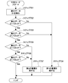
- FIG. 4 is a flowchart showing an example of the operation in the mode for determining the state of the GPS antenna 12.
- the determination mode may be set manually by the user or may be set at predetermined time intervals by a timer.
- control unit 18 When set in the determination mode, control unit 18 first inputs voltage Ve converted by current / voltage conversion unit 14 through impedance conversion unit 15, converts this into digital data, and obtains detection data D1. (Step 401).
- control unit 18 reads the short circuit threshold data D21 among the threshold data stored in the storage unit 16, and determines whether the data D1 is smaller than the short circuit threshold data D21 (step 402) .
- the control unit 18 stores the information in the storage unit 16.
- the disconnection threshold data D22 is read out, and it is determined whether the data D1 is larger than the disconnection threshold data D22 (step 403).
- the control unit 18 determines that the state of the GPS antenna 12 is The discrimination mode is ended assuming that it is normal.
- the control unit 18 considers that the possibility of the GPS antenna 12 shorting is high, or In the case of No, that is, when the detection data D1 is smaller than the disconnection threshold data D22, it is considered that the GPS antenna 12 is highly likely to be disconnected, and an alarm is issued from the alarm unit 19 (step 404).
- the determination result by the determination unit may be notified to the PC 21 by wire or wirelessly. Thereby, the user can recognize the presence or absence of abnormality of the antenna 12.
- FIG. 5 is a flowchart showing an example of the operation in the rewrite mode of the threshold data stored in the storage unit 16.
- the rewrite mode may be set when the PC 21 is connected to the external interface unit 17 or may be set by the setting of the rewrite mode by the PC 21. Further, it may be set by setting of the rewrite mode by the PC 21 through the communication line (wireless / wired) 22.
- the control unit 18 waits for the input of rewrite data from the PC 21 via the external interface unit 17 (step 501).
- control unit 18 determines whether the data is the short circuit threshold data D21 among the threshold data (step 502).
- the control unit 18 determines that the data is the disconnection threshold data D22. (Step 503).
- the determination as to whether the short circuit threshold data D21 or the disconnection threshold data D22 can be made by, for example, providing an identification flag in the header of the data, or can be realized by other known techniques.
- the control unit 18 has stored the short circuit threshold data D21 so far in the storage unit 16 until then. It rewrites with short circuit threshold data D21 (Step 504). Further, when the data input from the PC 21 is the disconnection threshold data D22 among the threshold data, the control unit 18 has been stored in the storage unit 16 by the disconnection threshold data D22. The disconnection threshold data D22 is rewritten (step 505).
- the threshold data corresponding to V21 and V22 indicated by the dotted line in FIG. 3 (stored in the storage unit 16), which are thresholds for alarming a short circuit or disconnection of the GPS antenna 12 according to the above-described rewriting mode.
- the user can rewrite the short circuit threshold data D21 and the disconnection threshold data D22) using the PC 21.
- the control unit 18 detects that the detected data D1 exceeds the threshold (D21) or falls below the threshold (D22) due to the change of the voltage Ve, or the GPS antenna 12 is shorted or broken by mistake, or There is a possibility that it may be determined that there is a high possibility of short circuit or disconnection.
- the threshold data (short circuit) stored in the storage unit 16 is considered in consideration of the change in the resistance Rg of the GPS antenna 12.
- the threshold value data D21 and the disconnection threshold data D22) are rewritten. As a result, it is possible to prevent erroneous determination that the GPS antenna 12 is highly likely to be shorted or broken or shorted or broken.
- the resistance Rg of the GPS antenna 12 may change. Even in such a case, the current flowing from the antenna current source 13 to the current / voltage conversion unit 14 and the GPS antenna 12 changes, and there is a possibility that the GPS antenna 12 is erroneously shorted or disconnected. It is possible to determine that it is high. In this case as well, the threshold data stored in the storage unit 16 can be rewritten with threshold data corresponding to the new GPS antenna 12 to prevent an erroneous determination.
- the vehicle position information notification device 1 since the vehicle position information notification device 1 according to the present embodiment is configured to allow the user to rewrite the threshold value used to determine the state of the GPS antenna 12, the characteristics of the GPS antenna 12 can be obtained. It is not determined that the GPS antenna 12 is accidentally shorted or broken due to aging or replacement, or the possibility of shorting or breakage is high. Therefore, for example, the user is not accidentally replaced even though the GPS antenna 12 is normal.
- the short circuit or disconnection of the GPS antenna 12 is determined. However, in the second embodiment, it is determined whether the GPS antenna 12 approaches the short circuit or the GPS antenna 12 approaches the disconnection. It also determines whether it has come.
- the vehicle position information notification device 1 according to the second embodiment can have the same configuration as the device configuration shown in FIG. 1, but differs in the following points with respect to the storage unit 16 and the control unit 18.
- the storage unit 16 of the vehicle position information notification device 1 determines whether the GPS antenna 12 approaches a short circuit.
- the threshold data D31 of whether or not and the threshold data D32 of whether or not the GPS antenna 12 has come close to disconnection are rewritably stored as threshold data.
- the threshold data D31 as to whether or not the GPS antenna 12 approaches a short circuit has a predetermined value smaller than the short circuit threshold data D21, for example, a value such as a short circuit expected after several months. It is set.
- the threshold data D32 as to whether or not the GPS antenna 12 has come close to disconnection is set to a value larger than the disconnection threshold data D22, for example, a value such that disconnection may be expected several months later.
- FIG. 7 is a flowchart showing an example of the operation in the mode for determining the state of the GPS antenna 12 according to the second embodiment. This determination mode may also be set manually by the user or may be set at predetermined time intervals by a timer.
- control unit 18 When set in the determination mode, control unit 18 first inputs voltage Ve converted by current / voltage conversion unit 14 through impedance conversion unit 15, converts this into digital data, and obtains detection data D1. (Step 701).
- control unit 18 reads out the threshold data D31 among the threshold data stored in the storage unit 16 and determines whether the data D1 is smaller than the threshold data D31 (step 702).
- the control unit 18 stores the information in the storage unit 16.
- the threshold data D32 is read out of the threshold data, and it is determined whether the data D1 is larger than the threshold data D32 (step 703).
- Step 702 for example, point X in FIG. 6
- Step 703 the alarm unit indicates that the GPS antenna 12 is approaching a short circuit or the GPS antenna 12 is approaching a disconnection.
- a first alarm is issued from 19 to notify the user (step 704).
- control unit 18 reads out the threshold value data D21 among the threshold value data stored in the storage unit 16, and determines whether the data D1 is smaller than the threshold value data D21. It discriminates (step 705).
- step 705 If the data D1 is smaller than the threshold data D21 (Yes in step 705), that is, if the GPS antenna 12 can be regarded as having a low possibility of short circuit, the data D1 is higher than the disconnection threshold data D22. It is determined whether it is large (step 706).
- the controller 18 controls the GPS antenna 12 The discrimination mode is ended assuming that the state is normal.
- the alarm unit 19 issues a second alarm (step 404). It is preferable that the second alarm has a mode different from the first alarm, for example, in the case where the alarm is a sound, the volume and the pitch are different. Also in the present embodiment, the four threshold data D21, D22, D31, and D32 stored in the storage unit 16 can be rewritten as in the first embodiment.
- the threshold value data stored in the storage unit 16 can be rewritten, so that the GPS antenna 12 is shorted or disconnected. It is possible to prevent erroneous determination that the possibility is high.
- threshold data threshold data D31 as to whether or not the GPS antenna 12 has approached a short circuit and threshold data D32 as to whether or not the GPS antenna 12 has approached as a disconnection are used for GPS. Since the user is notified that the antenna 12 is approaching a short circuit or the GPS antenna 12 is approaching a disconnection, the user can prepare for a short circuit or disconnection for a long time.
- Such an alarm triggers the user to rewrite the threshold data stored in the storage unit 16 and erroneously determines that the possibility of short circuit or disconnection is high when the GPS antenna 12 is short circuit or disconnection. Can be prevented in advance and more reliably.
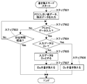
- FIG. 8 is a flow chart showing an example of the operation of the threshold data rewrite mode in the third embodiment.
- control unit 18 When the control unit 18 is set to the rewrite mode, the control unit 18 sends detection data, threshold data, and a determination result by the determination unit to the PC 21 via the external interface unit 17 (step 801). For example, detection data in the past, threshold data, and determination results by the determination unit may be stored in the storage unit 18 and sent to the PC 21. Thus, for example, the PC 21 can present the data shown in FIG. 3 to the user. Then, the user can appropriately set new threshold data (rewrite data) in the PC 21 based on these data.
- control unit 18 waits for input of rewrite data from the PC 21 through the external interface unit 17 (step 802).
- the rewrite data is not input from the PC 21 even after the predetermined time has passed (step 803), the rewrite mode is ended.
- control unit 18 determines whether the data is the short circuit threshold data D21 among the threshold data (step 804).
- the control unit 18 determines that the data is the disconnection threshold data D22. (Step 805).
- the control unit 18 detects the short circuit threshold data D21 stored in the storage unit 16 by the short circuit threshold data D21. And (step 806). Further, when the data inputted from the PC 21 is the disconnection threshold data D22, the control unit 18 causes the disconnection threshold data D22 which has been stored in the storage unit 16 by the disconnection threshold data D22. And (step 807).
- FIG. 9 is a block diagram showing a configuration of a vehicle position information notification device 1 according to a fourth embodiment of the present invention.
- the impedance conversion unit 15 is interposed between the current / voltage conversion unit 14 and the control unit 18, and the control unit 18 performs A / D conversion.
- the vehicle position information notification device 1 according to the fourth embodiment is provided with an A / D (analog / digital) conversion unit 95 instead of the impedance conversion unit 15, The A / D conversion is performed by the D conversion unit 95, and the A / D conversion unit 95 also functions as an impedance conversion unit.
- the processing load on the control unit 18 can be reduced without substantially increasing the number of parts.
- an antenna monitoring device concerning the present invention can be used similarly for other devices carrying an antenna.
- the GPS antenna has been described as an example of the antenna, it is needless to say that other antennas may be used.
- Vehicle Position Information Notification Device 10 Modem (Communication Unit) 11 GPS receiver 12 GPS antenna 13 antenna current source (detection unit) 14 Current / voltage converter (detector) 15 impedance conversion unit 16 storage unit 17 interface unit 18 control unit (determination unit, rewrite unit) 19 alarm unit 21 PC 22 Communication Line (Wireless / Wired) 30 management center device 95 A / D converter D1 detection data D21, D22, D31, D32 threshold data
Landscapes
- Engineering & Computer Science (AREA)
- Physics & Mathematics (AREA)
- Radar, Positioning & Navigation (AREA)
- Remote Sensing (AREA)
- General Physics & Mathematics (AREA)
- Computer Networks & Wireless Communication (AREA)
- Signal Processing (AREA)
- Electromagnetism (AREA)
- Position Fixing By Use Of Radio Waves (AREA)
- Alarm Systems (AREA)
- Emergency Alarm Devices (AREA)
- Input Circuits Of Receivers And Coupling Of Receivers And Audio Equipment (AREA)
Abstract
[Problem] To monitor an antenna state accurately even if the characteristics of an antenna change over time, said antenna is replaced, or the like. [Solution] This device 1 is provided with a GPS receiver 11, a GPS antenna 12, a modem 10 for transmitting vehicle location information received by the GPS receiver 11, an antenna current source 13 and a current/voltage conversion unit 14 that detect the state of the GPS antenna 12, a storage unit 16 that stores a modifiable threshold for the state of the GPS antenna 12, and a control unit 18 that determines the state of the GPS antenna 12 and modifies the threshold stored in the storage unit 16.
Description
本発明は、アンテナの短絡や断線などの故障を監視するためのアンテナ監視装置及びそのような監視機能を有する位置情報通知装置に関する。
The present invention relates to an antenna monitoring device for monitoring a failure such as a short circuit or disconnection of an antenna, and a position information notification device having such a monitoring function.
油圧ショベルなどの建設機械は、盗難などに備えて建設機械を管理するセンタ装置側で位置情報が把握されている。例えば、建設機械が管理センタ装置にGPSより得られた位置情報を送信する通信機能を有し、継続的に建設機械より管理センタ装置に位置情報を通知している。
In a construction machine such as a hydraulic shovel, position information is grasped by a center device that manages the construction machine in preparation for theft or the like. For example, the construction machine has a communication function of transmitting position information obtained by GPS to the management center device, and the construction machine continuously notifies the management center device of the position information.
このような位置情報の通知を継続的に行うためには、GPSに関する機能を長らく維持するための監視機能も必要になる。例えば、GPS受信機に接続されたアンテナが短絡や断線などで故障した場合に、それを警報するための監視装置を設けることが考えられている。
In order to continuously notify such position information, a monitoring function for maintaining the function related to GPS for a long time is also required. For example, it has been considered to provide a monitoring device for alarming an antenna connected to the GPS receiver when it fails due to a short circuit or a disconnection.
特許文献1には、抵抗を介してケーブル外皮及びアンテナに直流電流を流し、コンパレータでケーブル外皮の電圧と予め設定された固有のしきい電圧(直流電源の電圧)とを比較し、ケーブル外皮の電圧がしきい値の電圧となったときにそれを断線として検出する技術が開示されている。
In Patent Document 1, direct current is applied to the cable sheath and the antenna via a resistor, and the voltage of the cable sheath is compared with a preset inherent threshold voltage (voltage of the DC power supply) by a comparator. There is disclosed a technique for detecting a break as a voltage reaches a threshold voltage.
アンテナの特性は経時変化し、またアンテナを別品に交換した場合などにはアンテナの特性が異なってしまうこともある。これに対して、特許文献1に開示された検出技術では、しきい値の電圧が固定されているので、アンテナの特性の経時変化やアンテナ交換によって誤検出が発生するおそれがある。
The characteristics of the antenna change with time, and when the antenna is replaced with another product, the characteristics of the antenna may differ. On the other hand, in the detection technique disclosed in Patent Document 1, since the threshold voltage is fixed, there is a possibility that false detection may occur due to the time-dependent change of antenna characteristics or antenna replacement.
以上のような事情に鑑み、本発明の目的は、アンテナの特性の経時変化やアンテナ交換などがあってもアンテナの状態を正確に監視することができるアンテナ監視装置及び位置情報通知装置を提供することにある。
In view of the circumstances as described above, it is an object of the present invention to provide an antenna monitoring device and a position information notification device capable of accurately monitoring the state of the antenna even if there is a time-dependent change in antenna characteristics or antenna replacement. It is.
上記目的を達成するため、本発明の一形態に係るアンテナ監視装置は、アンテナの状態を検出する検出部と、前記アンテナの状態に対するしきい値を書き換え可能に記憶する記憶部と、前記検出部による検出結果と前記記憶部に記憶されたしきい値とを比較し、比較結果に基づき前記アンテナの状態を判別する判別部と、前記記憶部に記憶されたしきい値を書き換える書き換え部とを具備する。
In order to achieve the above object, an antenna monitoring apparatus according to an aspect of the present invention includes a detection unit that detects a state of an antenna, a storage unit that rewritably stores a threshold for the state of the antenna, and the detection unit. A determination unit that compares the detection result obtained by the detection unit with the threshold stored in the storage unit and determines the state of the antenna based on the comparison result; and a rewriting unit that rewrites the threshold stored in the storage unit. Prepare.
本発明の一形態に係るアンテナ監視装置では、アンテナの状態に対するしきい値を書き換え可能にしたので、アンテナの特性の経時変化やアンテナ交換などがあってもアンテナの状態を正確に監視することができる。
In the antenna monitoring device according to one aspect of the present invention, the threshold value for the state of the antenna can be rewritten, so that the state of the antenna can be accurately monitored even if there is a time-dependent change in antenna characteristics or antenna replacement. it can.
本発明の一形態に係るアンテナ監視装置は、前記書き換え部により書き換えるためのしきい値を入力するための端末装置又は通信回線が接続される外部インターフェース部を更に具備してもよい。
これにより、外部の端末装置によりアンテナの状態に対するしきい値の書き換えを簡単に行うことができる。
本発明の一形態に係るアンテナ監視装置は、前記判別部による判別結果に応じて警報を行う警報部を更に具備してもよい。
これにより、ユーザに対してアンテナの交換時期を知らせることができる。 The antenna monitoring device according to an aspect of the present invention may further include an external interface unit to which a terminal device or a communication line for inputting a threshold value to be rewritten by the rewriting unit is connected.
Thereby, the external terminal device can easily rewrite the threshold value for the state of the antenna.
The antenna monitoring device according to an aspect of the present invention may further include a warning unit that gives a warning according to the determination result by the determination unit.
This allows the user to be notified of the antenna replacement time.
本発明の一形態に係るアンテナ監視装置は、前記記憶部が、前記アンテナが短絡した場合のしきい値又は前記アンテナが断線した場合のしきい値を書き換え可能に記憶し、前記判別部が、比較結果に基づき前記アンテナの状態を判別するものであってもよい。
これにより、アンテナを誤って短絡又は断線、或いはその可能性が高いと判別することはなくなる。 In the antenna monitoring device according to one aspect of the present invention, the storage unit rewritably stores a threshold value when the antenna is shorted or a threshold value when the antenna is disconnected, and the determination unit The state of the antenna may be determined based on the comparison result.
As a result, the antenna is not erroneously determined to be short circuit or disconnection, or high possibility thereof.
本発明の一形態に係るアンテナ監視装置は、前記記憶部が、前記アンテナが短絡に近づいてきたかどうかのしきい値又は前記アンテナが断線に近づいてきたかどうかのしきい値を書き換え可能に記憶し、前記判別部は、比較結果に基づき前記アンテナが短絡に近づいてきたかどうか又は前記アンテナが断線に近づいてきたかどうかを判別するものであってもよい。
In the antenna monitoring device according to one aspect of the present invention, the storage unit rewritably stores a threshold value as to whether the antenna has approached a short circuit or as to whether the antenna has approached a disconnection. The determination unit may determine whether the antenna has approached a short circuit or whether the antenna has approached disconnection based on a comparison result.
これにより、ユーザはかなり前から短絡や断線に対する準備をすることが可能となる。また、このような警報は、ユーザにとってはしきい値を書き換えるトリガーとなり、アンテナが短絡している、或いは断線していると誤って判別することを未然にかつより確実に防止することができる。
This allows the user to be prepared for shorts and breaks for quite some time. In addition, such an alarm serves as a trigger for rewriting the threshold value for the user, and erroneously determining that the antenna is short circuited or disconnected can be prevented in advance and more surely.
本発明の一形態に係る車両位置情報通知装置は、車両に搭載され、当該車両の位置情報を通知するための車両位置情報通知装置であって、前記車両の位置情報を得るためのGPS受信機及びGPS用アンテナと、前記GPS受信機より受信された車両の位置情報を送信するための通信部と、前記GPS用アンテナの状態を検出する検出部と、前記GPS用アンテナの状態に対するしきい値を書き換え可能に記憶する記憶部と、前記検出部による検出結果と前記記憶部に記憶されたしきい値とを比較し、比較結果に基づき前記GPS用の状態を判別する判別部と、前記記憶部に記憶されたしきい値を書き換える書き換え部と、を具備する。
A vehicle position information notification device according to one aspect of the present invention is a vehicle position information notification device mounted on a vehicle for notifying the position information of the vehicle, and a GPS receiver for obtaining the position information of the vehicle And a GPS antenna, a communication unit for transmitting position information of the vehicle received from the GPS receiver, a detection unit for detecting the state of the GPS antenna, and a threshold value for the state of the GPS antenna Storage unit for rewritably storing, a determination unit for comparing the detection result by the detection unit with the threshold value stored in the storage unit, and determining the state for the GPS based on the comparison result, and the storage And a rewrite unit that rewrites the threshold stored in the unit.
本発明の一形態に係る車両位置情報通知装置では、GPS用アンテナの状態に対するしきい値を書き換え可能にしたので、GPS用アンテナの特性の経時変化やGPS用アンテナ交換などがあってもGPS用アンテナの状態を正確に監視することができる。
In the vehicle position information notification device according to one aspect of the present invention, the threshold value for the state of the GPS antenna can be rewritten. Therefore, even if there are changes with time of the characteristics of the GPS antenna or replacement of the GPS antenna, etc. The condition of the antenna can be monitored accurately.
本発明の一形態に係るプログラムは、アンテナの状態を検出するステップと、前記アンテナの状態に対するしきい値を書き換え可能に記憶部に記憶させるステップと、前記検出結果と前記記憶部に記憶されたしきい値とを比較し、比較結果に基づき前記アンテナの状態を判別するステップと、前記記憶部に記憶されたしきい値を書き換えるステップとをコンピュータに実行させるものである。
A program according to an aspect of the present invention includes the steps of: detecting a state of an antenna; storing a threshold value for the state of the antenna in a storage unit in a rewritable manner; and storing the detection result and the storage unit. The computer is made to execute the steps of comparing with a threshold and determining the state of the antenna based on the comparison result, and rewriting the threshold stored in the storage unit.
本発明の一形態に係るプログラムでは、アンテナの状態に対するしきい値を書き換え可能にしたので、アンテナの特性の経時変化やアンテナ交換などがあってもアンテナの状態を正確に監視することができる。
In the program according to one aspect of the present invention, the threshold value for the state of the antenna can be rewritten, so that the state of the antenna can be accurately monitored even if the characteristics of the antenna change with time or the antenna is replaced.
本発明によれば、アンテナの特性の経時変化やアンテナ交換などがあってもアンテナの状態を正確に監視することができる。
According to the present invention, it is possible to accurately monitor the state of the antenna even if there is a time-dependent change in the characteristics of the antenna or antenna replacement.
以下、図面を参照しながら、本発明の実施形態を説明する。
(実施形態1)
図1は本発明の第1の実施形態に係る車両位置情報通知装置の構成を示すブロック図である。 Hereinafter, embodiments of the present invention will be described with reference to the drawings.
(Embodiment 1)
FIG. 1 is a block diagram showing a configuration of a vehicle position information notification device according to a first embodiment of the present invention.
図1に示すように、この車両位置情報通知装置1は、典型的には油圧シャベルなどの建設機械に搭載され、当該車両の位置情報を遠隔地の管理センタ装置30に通知するものである。
As shown in FIG. 1, the vehicle position information notification device 1 is typically mounted on a construction machine such as a hydraulic shovel and notifies the management center device 30 of a remote location of the position information of the vehicle.
車両位置情報通知装置1は、モデム10、GPS(Global Positioning System)受信機11及びGPS用アンテナ12と、アンテナ電流源13と、電流/電圧変換部14と、インピーダンス変換部15と、記憶部16と、外部インターフェース部17と、制御部18と、警報部19とを有する。
GPS受信機11及びGPS用アンテナ12は、GPSを使ってこの車両位置情報通知装置1を搭載する車両の位置情報を得る。 The vehicle position information notification device 1 includes amodem 10, a GPS (Global Positioning System) receiver 11 and a GPS antenna 12, an antenna current source 13, a current / voltage converter 14, an impedance converter 15, and a memory 16. , The external interface unit 17, the control unit 18, and the alarm unit 19.
TheGPS receiver 11 and the GPS antenna 12 use GPS to obtain position information of a vehicle equipped with the vehicle position information notification device 1.
GPS受信機11及びGPS用アンテナ12は、GPSを使ってこの車両位置情報通知装置1を搭載する車両の位置情報を得る。 The vehicle position information notification device 1 includes a
The
この車両の位置情報は、制御部18の制御の基で通信部としてのモデム10を介して例えば定期的に管理センタ装置30に送信される。車両位置情報通知装置1は、基本的にはこのような機能を有するが、本実施形態に係る車両位置情報通知装置1は、アンテナ電流源13及び電流/電圧変換部14を有する検出部と、インピーダンス変換部15と、記憶部16と、外部インターフェース部17と、警報部19と、これらを制御する制御部18とから構成されるアンテナ監視装置2としての機能が付加されている。
The position information of the vehicle is periodically transmitted, for example, to the management center apparatus 30 via the modem 10 as a communication unit under the control of the control unit 18. The vehicle position information notification device 1 basically has such a function, but the vehicle position information notification device 1 according to the present embodiment has a detection unit having an antenna current source 13 and a current / voltage conversion unit 14; The function as the antenna monitoring apparatus 2 comprised from the impedance conversion part 15, the memory | storage part 16, the external interface part 17, the alarm part 19, and the control part 18 which controls these is added.
ここで、アンテナ電流源13は、GPS用アンテナ12に5V又は3V程度の直流の定電圧を印加し、GPS用アンテナ12に当該GPS用アンテナ12の状態を判別するための電流を流す。GPS用アンテナ12には、アンテナ本体の他に、同軸ケーブル、コネクタなども含まれる。
Here, the antenna current source 13 applies a DC constant voltage of about 5 V or 3 V to the GPS antenna 12 and supplies a current for determining the state of the GPS antenna 12 to the GPS antenna 12. The GPS antenna 12 includes a coaxial cable, a connector and the like in addition to the antenna main body.
電流/電圧変換部14は、GPS用アンテナ12とアンテナ電流源13との間に介挿され、アンテナ電流源13よりGPS用アンテナ12に流れる電流に応じた値の電圧に変換する。
インピーダンス変換部15は、電流/電圧変換部14と制御部18との間でインピーダンス変換を調整する。 The current /voltage conversion unit 14 is interposed between the GPS antenna 12 and the antenna current source 13 and converts the voltage into a voltage according to the current flowing from the antenna current source 13 to the GPS antenna 12.
The impedance converter 15 adjusts impedance conversion between the current /voltage converter 14 and the controller 18.
インピーダンス変換部15は、電流/電圧変換部14と制御部18との間でインピーダンス変換を調整する。 The current /
The impedance converter 15 adjusts impedance conversion between the current /
記憶部16は、GPS用アンテナ12の状態に応じた所定のしきい値としてのデータ(しきい値データ)を書き換え可能に記憶する。記憶部16は、データの書き換えが可能なメモリ素子によって構成される。
The storage unit 16 rewrites and stores data (threshold data) as a predetermined threshold according to the state of the GPS antenna 12. The storage unit 16 is configured of a memory element capable of rewriting data.
外部インターフェース部17は、外部との間でデータのやり取りをするためのインターフェースである。ユーザは、外部インターフェース部17に接続された端末装置としてのパーソナルコンピュータ(PC)21により、或いは外部インターフェース部17に接続された通信回線(無線・有線)22を介したPC21により、当該車両位置情報通知装置1との間でデータのやり取りを行う。これにより、ユーザは、PC21を使って記憶部16に記憶されたしきい値データを書き換えたり、後述する判別部による判別結果を認識したりすることができるようになっている。なお、端末装置としては、PCの他にスマートフォンや携帯電話などを用いることができる。
The external interface unit 17 is an interface for exchanging data with the outside. The user can use the personal computer (PC) 21 as a terminal device connected to the external interface unit 17 or the PC 21 via the communication line (wireless / wired) 22 connected to the external interface unit 17 to obtain the vehicle position information. Data is exchanged with the notification device 1. Thereby, the user can rewrite the threshold value data stored in the storage unit 16 using the PC 21 and can recognize the determination result by the determination unit described later. In addition to a PC, a smartphone, a mobile phone, or the like can be used as the terminal device.
制御部18は、インピーダンス変換部15により変換されたアナログ信号としての電圧をその値に応じたディジタルデータに変換する。また、制御部18は、このデータ(検出データ)及び記憶部16に記憶されたしきい値データに基づきGPS用アンテナ12の状態を判別する。更に、制御部18は、上記のしきい値データの書き換えを含め、車両位置情報通知装置1全体を制御する。すなわち、制御部18は、判別部及び書き換え部としての機能を有する。
The control unit 18 converts the voltage as an analog signal converted by the impedance conversion unit 15 into digital data according to the value. Further, the control unit 18 determines the state of the GPS antenna 12 based on the data (detection data) and the threshold data stored in the storage unit 16. Furthermore, the control unit 18 controls the entire vehicle position information notification device 1 including the above-described rewriting of the threshold value data. That is, the control unit 18 has functions as a determination unit and a rewriting unit.
警報部19は、GPS用アンテナ12の状態に応じて、例えば短絡や断線が発生する可能性がある場合に所定の警報を行う。警報部19による警報は、例えば警報音の鳴動や警報表示などにより行うことができる。
The alarm unit 19 performs a predetermined alarm, for example, when there is a possibility that a short circuit or a disconnection may occur, in accordance with the state of the GPS antenna 12. The alarm by the alarm unit 19 can be performed, for example, by ringing of an alarm sound or alarm display.
図2は上記の電流/電圧変換部14及びインピーダンス変換部15の構成例を示す図である。
同図に示すように、電流/電圧変換部14の抵抗14Aと抵抗として考えることができるGPS用アンテナ12とは、アンテナ電流源13とグランドGとの間で直列に接続されている。電流/電圧変換部14は、抵抗14Aの両端に接続端子14B、14Cを有する。接続端子14B、14C間の電位差が、アンテナ電流源13よりGPS用アンテナ12に流れる電流の値に応じた電圧である。例えば、アンテナ電流源13よりGPS用アンテナ12に流れる電流が大きくなれば電圧が大きくなり、アンテナ電流源13よりGPS用アンテナ12に流れる電流が小さくなれば電圧が小さくなる。
インピーダンス変換部15は、例えば抵抗R1~R4及びオペアンプOPからなる差動増幅器により構成される。 FIG. 2 is a view showing a configuration example of the current /voltage conversion unit 14 and the impedance conversion unit 15 described above.
As shown in the figure, theresistor 14A of the current / voltage converter 14 and the GPS antenna 12 that can be considered as a resistor are connected in series between the antenna current source 13 and the ground G. The current / voltage converter 14 has connection terminals 14B and 14C at both ends of the resistor 14A. The potential difference between the connection terminals 14B and 14C is a voltage corresponding to the value of the current flowing from the antenna current source 13 to the GPS antenna 12. For example, if the current flowing from the antenna current source 13 to the GPS antenna 12 increases, the voltage increases, and if the current flowing from the antenna current source 13 to the GPS antenna 12 decreases, the voltage decreases.
Theimpedance conversion unit 15 is configured of, for example, a differential amplifier including resistors R1 to R4 and an operational amplifier OP.
同図に示すように、電流/電圧変換部14の抵抗14Aと抵抗として考えることができるGPS用アンテナ12とは、アンテナ電流源13とグランドGとの間で直列に接続されている。電流/電圧変換部14は、抵抗14Aの両端に接続端子14B、14Cを有する。接続端子14B、14C間の電位差が、アンテナ電流源13よりGPS用アンテナ12に流れる電流の値に応じた電圧である。例えば、アンテナ電流源13よりGPS用アンテナ12に流れる電流が大きくなれば電圧が大きくなり、アンテナ電流源13よりGPS用アンテナ12に流れる電流が小さくなれば電圧が小さくなる。
インピーダンス変換部15は、例えば抵抗R1~R4及びオペアンプOPからなる差動増幅器により構成される。 FIG. 2 is a view showing a configuration example of the current /
As shown in the figure, the
The
ここで、アンテナ電流源13の電圧をVo、GPS用アンテナ12の抵抗をRg、電流/電圧変換部14の抵抗14AをRcとすると、電流/電圧変換部14の抵抗14Aに印加される電圧Veは、
Ve=Vo×Rc/(Rc+Rg)
となる。 Here, assuming that the voltage of the antennacurrent source 13 is Vo, the resistance of the GPS antenna 12 is Rg, and the resistance 14A of the current / voltage conversion unit 14 is Rc, the voltage Ve applied to the resistance 14A of the current / voltage conversion unit 14 Is
Ve = Vo × Rc / (Rc + Rg)
It becomes.
Ve=Vo×Rc/(Rc+Rg)
となる。 Here, assuming that the voltage of the antenna
Ve = Vo × Rc / (Rc + Rg)
It becomes.
ここで、GPS用アンテナ12が短絡した場合には、Rgは0Ωとなり、Ve=Voとなる。一方、GPS用アンテナ12が断線した場合には、Rgは∞Ωとなり、Ve=0Vとなる。
Here, when the GPS antenna 12 is short-circuited, Rg is 0Ω, and Ve = Vo. On the other hand, when the GPS antenna 12 is disconnected, Rg is ΩΩ, and Ve = 0V.
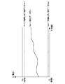
GPS用アンテナ12が短絡や断線をしない場合であっても劣化などのその特性の経時変化によってRgが変化するので、Veは例えば図3に示すように経時的に変化する。このVeを、インピーダンス変換部15を経て制御部18にてディジタル変換したものが検出データD1となる。
Even if the GPS antenna 12 does not short or break, Rg changes due to the time-dependent change of its characteristics such as deterioration, so Ve changes with time as shown in FIG. 3, for example. What passes through the impedance conversion unit 15 and is digitally converted by the control unit 18 becomes the detection data D1.
記憶部16に記憶されたしきい値としてのデータは、GPS用アンテナ12の状態(短絡や断線など)に応じた所定のしきい値に対応するディジタルデータである。典型的な一例として、GPS用アンテナ12が短絡したときのVoより少し低い電圧V21をディジタル変換した短絡しきい値データD21及びGPS用アンテナ12が断線したときの0Vより少し高い電圧V22をディジタル変換した断線しきい値データD22がしきい値データとして記憶部16に記憶される。勿論、実質的にV21=Vo、V22=0としても構わない。また、本実施形態においては、しきい値データとして、短絡に対する短絡しきい値データ及び断線に対する断線しきい値データであったが、いずれか一方であっても構わない。
The data as the threshold value stored in the storage unit 16 is digital data corresponding to a predetermined threshold value according to the state (short circuit, disconnection or the like) of the GPS antenna 12. As a typical example, short-circuit threshold data D21 obtained by digitally converting a voltage V21 slightly lower than Vo when the GPS antenna 12 is short-circuited and digital conversion of a voltage V22 slightly higher than 0 V when the GPS antenna 12 is broken The disconnected threshold data D22 is stored in the storage unit 16 as threshold data. Of course, V21 = Vo and V22 = 0 may be substantially set. Moreover, in this embodiment, although it was the short circuit threshold data with respect to a short circuit and the disconnection threshold data with respect to a disconnection as threshold value data, any one may be sufficient.
図4はGPS用アンテナ12の状態を判別するモードでの動作の一例を示すフローチャートである。この判別モードは、ユーザが手動で設定してもよいし、タイマによって所定の時間間隔で設定されるものであってもよい。
FIG. 4 is a flowchart showing an example of the operation in the mode for determining the state of the GPS antenna 12. The determination mode may be set manually by the user or may be set at predetermined time intervals by a timer.
制御部18は、判別モードに設定されると、まず電流/電圧変換部14より変換された電圧Veを、インピーダンス変換部15を経て入力し、これをディジタルデータに変換し、検出データD1を得る(ステップ401)。
When set in the determination mode, control unit 18 first inputs voltage Ve converted by current / voltage conversion unit 14 through impedance conversion unit 15, converts this into digital data, and obtains detection data D1. (Step 401).
次に、制御部18は、記憶部16に記憶されたしきい値データのうち短絡しきい値データD21を読み出し、データD1が短絡しきい値データD21よりも小さいかを判別する(ステップ402)。
Next, the control unit 18 reads the short circuit threshold data D21 among the threshold data stored in the storage unit 16, and determines whether the data D1 is smaller than the short circuit threshold data D21 (step 402) .
検出データD1が短絡しきい値データD21よりも小さい場合には(ステップ402のYes)、すなわちGPS用アンテナ12が短絡する可能性が低い場合には、制御部18は、記憶部16に記憶されたしきい値データのうち断線しきい値データD22を読み出し、データD1が断線しきい値データD22よりも大きいかを判別する(ステップ403)。
When the detection data D1 is smaller than the short circuit threshold data D21 (Yes in step 402), that is, when the possibility that the GPS antenna 12 is shorted is low, the control unit 18 stores the information in the storage unit 16. Among the threshold data, the disconnection threshold data D22 is read out, and it is determined whether the data D1 is larger than the disconnection threshold data D22 (step 403).
検出データD1が断線しきい値データD22よりも大きい場合には(ステップ403のYes)、すなわちGPS用アンテナ12が断線する可能性が低い場合には、制御部18はGPS用アンテナ12の状態が正常とみなして判別モードを終了する。
If the detection data D1 is larger than the disconnection threshold data D22 (Yes in step 403), that is, if the possibility that the GPS antenna 12 is disconnected is low, the control unit 18 determines that the state of the GPS antenna 12 is The discrimination mode is ended assuming that it is normal.
一方、制御部18は、ステップ402でNoの場合、すなわち検出データD1が短絡しきい値データD21よりも大きい場合には、GPS用アンテナ12が短絡する可能性が高いとみなし、或いはステップ403でNoの場合、すなわち検出データD1が断線しきい値データD22よりも小さい場合には、GPS用アンテナ12が断線する可能性が高いとみなし、警報部19より警報を発する(ステップ404)。
なお、判別モードの終了前に、判別部による判別結果を有線又は無線でPC21に通知しても良い。これにより、ユーザはアンテナ12の異常の有無を認識することができる。 On the other hand, in the case of No at Step 402, that is, when the detection data D1 is larger than the short circuit threshold data D21, thecontrol unit 18 considers that the possibility of the GPS antenna 12 shorting is high, or In the case of No, that is, when the detection data D1 is smaller than the disconnection threshold data D22, it is considered that the GPS antenna 12 is highly likely to be disconnected, and an alarm is issued from the alarm unit 19 (step 404).
In addition, before the end of the determination mode, the determination result by the determination unit may be notified to thePC 21 by wire or wirelessly. Thereby, the user can recognize the presence or absence of abnormality of the antenna 12.
なお、判別モードの終了前に、判別部による判別結果を有線又は無線でPC21に通知しても良い。これにより、ユーザはアンテナ12の異常の有無を認識することができる。 On the other hand, in the case of No at Step 402, that is, when the detection data D1 is larger than the short circuit threshold data D21, the
In addition, before the end of the determination mode, the determination result by the determination unit may be notified to the
図5は記憶部16に記憶されたしきい値データの書き換えモードでの動作の一例を示すフローチャートである。この書き換えモードは、外部インターフェース部17にPC21が接続されたときに設定されるようにし、或いはPC21による書き換えモードの設定により設定されるものであってもよい。また、通信回線(無線・有線)22を介したPC21による書き換えモードの設定により設定されるものであってもよい。
制御部18は、書き換えモードに設定されると、外部インターフェース部17を介してPC21からの書き換えデータの入力を待つ(ステップ501)。 FIG. 5 is a flowchart showing an example of the operation in the rewrite mode of the threshold data stored in thestorage unit 16. The rewrite mode may be set when the PC 21 is connected to the external interface unit 17 or may be set by the setting of the rewrite mode by the PC 21. Further, it may be set by setting of the rewrite mode by the PC 21 through the communication line (wireless / wired) 22.
When thecontrol unit 18 is set to the rewrite mode, the control unit 18 waits for the input of rewrite data from the PC 21 via the external interface unit 17 (step 501).
制御部18は、書き換えモードに設定されると、外部インターフェース部17を介してPC21からの書き換えデータの入力を待つ(ステップ501)。 FIG. 5 is a flowchart showing an example of the operation in the rewrite mode of the threshold data stored in the
When the
次に、制御部18は、PC21から書き換えデータが入力されると、そのデータがしきい値データのうち短絡しきい値データD21かどうかを判断する(ステップ502)。
Next, when the rewrite data is input from the PC 21, the control unit 18 determines whether the data is the short circuit threshold data D21 among the threshold data (step 502).
また、制御部18は、PC21から入力されたデータがしきい値データのうち短絡しきい値データD21でない場合には(ステップ502のNo)、そのデータを断線しきい値データD22であると判断する(ステップ503)。
In addition, when the data input from the PC 21 is not the short circuit threshold data D21 among the threshold data (No in step 502), the control unit 18 determines that the data is the disconnection threshold data D22. (Step 503).
以上の短絡しきい値データD21か断線しきい値データD22かの判断は例えばデータのヘッダに識別フラグを設けることによって行うことが可能であるし、その他周知の技術によっても実現することができる。
The determination as to whether the short circuit threshold data D21 or the disconnection threshold data D22 can be made by, for example, providing an identification flag in the header of the data, or can be realized by other known techniques.
そして、制御部18は、PC21から入力されたデータがしきい値データのうち短絡しきい値データD21である場合には、その短絡しきい値データD21によってそれまで記憶部16に記憶されていた短絡しきい値データD21と書き換える(ステップ504)。また、制御部18は、PC21から入力されたデータがしきい値データのうち断線しきい値データD22である場合には、その断線しきい値データD22によってそれまで記憶部16に記憶されていた断線しきい値データD22と書き換える(ステップ505)。
Then, when the data input from the PC 21 is the short circuit threshold data D21 among the threshold data, the control unit 18 has stored the short circuit threshold data D21 so far in the storage unit 16 until then. It rewrites with short circuit threshold data D21 (Step 504). Further, when the data input from the PC 21 is the disconnection threshold data D22 among the threshold data, the control unit 18 has been stored in the storage unit 16 by the disconnection threshold data D22. The disconnection threshold data D22 is rewritten (step 505).
以上の書き換えモードによって、GPS用アンテナ12の短絡や断線などを警報するためのしきい値となる図3の点線で示したV21とV22に対応するしきい値データ(記憶部16に記憶された短絡しきい値データD21と断線しきい値データD22)をユーザがPC21を使って書き換えることが可能となる。
The threshold data corresponding to V21 and V22 indicated by the dotted line in FIG. 3 (stored in the storage unit 16), which are thresholds for alarming a short circuit or disconnection of the GPS antenna 12 according to the above-described rewriting mode. The user can rewrite the short circuit threshold data D21 and the disconnection threshold data D22) using the PC 21.
図3に示したように、GPS用アンテナ12は経時変化によって抵抗Rgが変化するので、アンテナ電流源13より電流/電圧変換部14を介してGPS用アンテナ12に流れる電流も変化する。従って、電流/電圧変換部14によって変換される電圧Veも変化する。制御部18は、この電圧Veの変化によって検出データD1がしきい値(D21)を超えたり、しきい値(D22)以下となったりし、誤ってGPS用アンテナ12が短絡・断線した、或いは短絡・断線する可能性が高いと判別する可能性がある。本実施形態に係る車両位置情報通知装置1では、例えばユーザが所定期間経過した場合に、GPS用アンテナ12の抵抗Rgの変化を考慮し、記憶部16に記憶されたしきい値データ(短絡しきい値データD21、断線しきい値データD22)を書き換える。これにより、GPS用アンテナ12が短絡・断線した、或いは短絡・断線する可能性が高いと誤って判別することを防止することができる。
As shown in FIG. 3, since the resistance Rg of the GPS antenna 12 changes with time, the current flowing from the antenna current source 13 to the GPS antenna 12 via the current / voltage conversion unit 14 also changes. Therefore, the voltage Ve converted by the current / voltage conversion unit 14 also changes. The control unit 18 detects that the detected data D1 exceeds the threshold (D21) or falls below the threshold (D22) due to the change of the voltage Ve, or the GPS antenna 12 is shorted or broken by mistake, or There is a possibility that it may be determined that there is a high possibility of short circuit or disconnection. In the vehicle position information notification device 1 according to the present embodiment, for example, when the user has passed a predetermined period, the threshold data (short circuit) stored in the storage unit 16 is considered in consideration of the change in the resistance Rg of the GPS antenna 12. The threshold value data D21 and the disconnection threshold data D22) are rewritten. As a result, it is possible to prevent erroneous determination that the GPS antenna 12 is highly likely to be shorted or broken or shorted or broken.
また、GPS用アンテナ12を別品に交換した場合などにもGPS用アンテナ12の抵抗Rgが変化することがある。このような場合にも、アンテナ電流源13より電流/電圧変換部14及びGPS用アンテナ12に流れる電流が変化し、誤ってGPS用アンテナ12が短絡・断線した、或いは短絡・断線する可能性が高いと判別する可能性がある。その場合にも、記憶部16に記憶されたしきい値データを新たなGPS用アンテナ12に対応したしきい値データに書き換えることで、誤った判別を防止することができる。
In addition, when the GPS antenna 12 is replaced with another product, the resistance Rg of the GPS antenna 12 may change. Even in such a case, the current flowing from the antenna current source 13 to the current / voltage conversion unit 14 and the GPS antenna 12 changes, and there is a possibility that the GPS antenna 12 is erroneously shorted or disconnected. It is possible to determine that it is high. In this case as well, the threshold data stored in the storage unit 16 can be rewritten with threshold data corresponding to the new GPS antenna 12 to prevent an erroneous determination.
すなわち、本実施形態に係る車両位置情報通知装置1は、GPS用アンテナ12の状態の判別に用いられるしきい値を、ユーザによって書き換えることができるように構成したので、GPS用アンテナ12の特性の経時変化や交換に起因してGPS用アンテナ12を誤って短絡・断線した、短絡・断線の可能性が高いなどと判別することはなくなる。したがって、例えばユーザが正常なGPS用アンテナ12であるにもかかわらず誤って交換するようなことはなくなる。
なお、しきい値はアンテナ電源13の電圧に応じて、自動的に設定するようにしても良い。例えば、アンテナ電源13が12Vの場合は、V21=11V、アンテナ電源13が24Vの場合は、V21=23Vなどを設定することで、アンテナ電源13の仕様に応じて適切なしきい値を容易に設定することができる。
(実施形態2)
次に、本発明の第2の実施形態を説明する。 That is, since the vehicle position information notification device 1 according to the present embodiment is configured to allow the user to rewrite the threshold value used to determine the state of theGPS antenna 12, the characteristics of the GPS antenna 12 can be obtained. It is not determined that the GPS antenna 12 is accidentally shorted or broken due to aging or replacement, or the possibility of shorting or breakage is high. Therefore, for example, the user is not accidentally replaced even though the GPS antenna 12 is normal.
The threshold may be automatically set according to the voltage of theantenna power supply 13. For example, by setting V21 = 11 V when antenna power supply 13 is 12 V and V21 = 23 V when antenna power supply 13 is 24 V, an appropriate threshold value can be easily set according to the specifications of antenna power supply 13. can do.
Second Embodiment
Next, a second embodiment of the present invention will be described.
なお、しきい値はアンテナ電源13の電圧に応じて、自動的に設定するようにしても良い。例えば、アンテナ電源13が12Vの場合は、V21=11V、アンテナ電源13が24Vの場合は、V21=23Vなどを設定することで、アンテナ電源13の仕様に応じて適切なしきい値を容易に設定することができる。
(実施形態2)
次に、本発明の第2の実施形態を説明する。 That is, since the vehicle position information notification device 1 according to the present embodiment is configured to allow the user to rewrite the threshold value used to determine the state of the
The threshold may be automatically set according to the voltage of the
Second Embodiment
Next, a second embodiment of the present invention will be described.
上記の実施形態においては、GPS用アンテナ12の短絡や断線を判別していたが、この第2の実施形態では、GPS用アンテナ12が短絡に近づいてきたかどうか及びGPS用アンテナ12が断線に近づいてきたかどうかについても判別するものである。
In the above embodiment, the short circuit or disconnection of the GPS antenna 12 is determined. However, in the second embodiment, it is determined whether the GPS antenna 12 approaches the short circuit or the GPS antenna 12 approaches the disconnection. It also determines whether it has come.
この第2の実施形態に係る車両位置情報通知装置1は、図1に示した装置構成と同様の構成をとることができるが、記憶部16及び制御部18について以下の点が異なる。
The vehicle position information notification device 1 according to the second embodiment can have the same configuration as the device configuration shown in FIG. 1, but differs in the following points with respect to the storage unit 16 and the control unit 18.
ここで、第2の実施形態に係る車両位置情報通知装置1の記憶部16は、短絡しきい値データD21及びG断線しきい値データD22の他に、GPS用アンテナ12が短絡に近づいてきたかどうかのしきい値データD31及びGPS用アンテナ12が断線に近づいてきたかどうかのしきい値データD32をしきい値データとして書き換え可能に記憶する。
Here, in addition to the short circuit threshold data D21 and the G disconnection threshold data D22, the storage unit 16 of the vehicle position information notification device 1 according to the second embodiment determines whether the GPS antenna 12 approaches a short circuit. The threshold data D31 of whether or not and the threshold data D32 of whether or not the GPS antenna 12 has come close to disconnection are rewritably stored as threshold data.
図6に示すように、GPS用アンテナ12が短絡に近づいてきたかどうかのしきい値データD31は、短絡しきい値データD21より小さい所定の値、例えば数カ月後に短絡が予想されるような値が設定される。同様に、GPS用アンテナ12が断線に近づいてきたかどうかのしきい値データD32は、断線しきい値データD22より大きい値、例えば数カ月後に断線が予想されるような値が設定される。
As shown in FIG. 6, the threshold data D31 as to whether or not the GPS antenna 12 approaches a short circuit has a predetermined value smaller than the short circuit threshold data D21, for example, a value such as a short circuit expected after several months. It is set. Similarly, the threshold data D32 as to whether or not the GPS antenna 12 has come close to disconnection is set to a value larger than the disconnection threshold data D22, for example, a value such that disconnection may be expected several months later.
図7はこの第2の実施形態に係るGPS用アンテナ12の状態を判別するモードでの動作の一例を示すフローチャートである。この判別モードも、ユーザが手動で設定してもよいし、タイマによって所定の時間間隔で設定されるものであってもよい。
FIG. 7 is a flowchart showing an example of the operation in the mode for determining the state of the GPS antenna 12 according to the second embodiment. This determination mode may also be set manually by the user or may be set at predetermined time intervals by a timer.
制御部18は、判別モードに設定されると、まず電流/電圧変換部14より変換された電圧Veを、インピーダンス変換部15を経て入力し、これをディジタルデータに変換し、検出データD1を得る(ステップ701)。
When set in the determination mode, control unit 18 first inputs voltage Ve converted by current / voltage conversion unit 14 through impedance conversion unit 15, converts this into digital data, and obtains detection data D1. (Step 701).
次に、制御部18は、記憶部16に記憶されたしきい値データのうちしきい値データD31を読み出し、データD1がしきい値データD31よりも小さいかを判別する(ステップ702)。
Next, the control unit 18 reads out the threshold data D31 among the threshold data stored in the storage unit 16 and determines whether the data D1 is smaller than the threshold data D31 (step 702).
検出データD1がしきい値データD31よりも小さい場合には(ステップ702のYes)、すなわちGPS用アンテナ12が短絡に近づいていないとみなせる場合には、制御部18は、記憶部16に記憶されたしきい値データのうちしきい値データD32を読み出し、データD1がしきい値データD32よりも大きいかを判別する(ステップ703)。
If the detection data D1 is smaller than the threshold data D31 (Yes in step 702), that is, if it can be considered that the GPS antenna 12 is not approaching a short circuit, the control unit 18 stores the information in the storage unit 16. The threshold data D32 is read out of the threshold data, and it is determined whether the data D1 is larger than the threshold data D32 (step 703).
そして、ステップ702のNo(例えば図6のX点)又はステップ703のNoの場合には、GPS用アンテナ12が短絡に近づいてきたこと又はGPS用アンテナ12が断線に近づいてきたことを警報部19よりユーザに知らせるための第1の警報を発する(ステップ704)。
Then, in the case of No in Step 702 (for example, point X in FIG. 6) or No in Step 703, the alarm unit indicates that the GPS antenna 12 is approaching a short circuit or the GPS antenna 12 is approaching a disconnection. A first alarm is issued from 19 to notify the user (step 704).
一方、ステップ703のYesの場合には、制御部18は、記憶部16に記憶されたしきい値データのうちしきい値データD21を読み出し、データD1がしきい値データD21よりも小さいかを判別する(ステップ705)。
On the other hand, in the case of Yes in step 703, the control unit 18 reads out the threshold value data D21 among the threshold value data stored in the storage unit 16, and determines whether the data D1 is smaller than the threshold value data D21. It discriminates (step 705).
データD1がしきい値データD21よりも小さい場合には(ステップ705のYes)、すなわちGPS用アンテナ12が短絡の可能性が低いとみなせる場合には、データD1が断線しきい値データD22よりも大きいかを判別する(ステップ706)。
If the data D1 is smaller than the threshold data D21 (Yes in step 705), that is, if the GPS antenna 12 can be regarded as having a low possibility of short circuit, the data D1 is higher than the disconnection threshold data D22. It is determined whether it is large (step 706).
検出データD1が断線しきい値データD22よりも大きい場合には(ステップ706のYes)、すなわちGPS用アンテナ12が断線する可能性が低いとみなせる場合には、制御部18はGPS用アンテナ12の状態が正常とみなして判別モードを終了する。
If the detection data D1 is larger than the disconnection threshold data D22 (Yes in step 706), that is, if the possibility of disconnection of the GPS antenna 12 can be considered low, the controller 18 controls the GPS antenna 12 The discrimination mode is ended assuming that the state is normal.
一方、制御部18は、ステップ705でNoの場合、すなわち検出データD1が短絡しきい値データD21よりも大きい場合には、或いはステップ706でNoの場合、すなわち検出データD1が断線しきい値データD22よりも小さい場合には、警報部19より第2の警報を発する(ステップ404)。第2の警報は、第1の警報と異なる態様、例えば警報が音の場合には音量や音程を異なるものとした方が好ましい。
本実施形態においても、記憶部16に記憶された4つのしきい値データD21、D22、D31、D32について第1の実施形態と同様に書き換え可能である。 On the other hand, in the case of No at step 705, that is, when the detection data D1 is larger than the short circuit threshold data D21, or in the case of No at step 706, that is, the detection data D1 is the disconnection threshold data If it is smaller than D22, thealarm unit 19 issues a second alarm (step 404). It is preferable that the second alarm has a mode different from the first alarm, for example, in the case where the alarm is a sound, the volume and the pitch are different.
Also in the present embodiment, the four threshold data D21, D22, D31, and D32 stored in thestorage unit 16 can be rewritten as in the first embodiment.
本実施形態においても、記憶部16に記憶された4つのしきい値データD21、D22、D31、D32について第1の実施形態と同様に書き換え可能である。 On the other hand, in the case of No at step 705, that is, when the detection data D1 is larger than the short circuit threshold data D21, or in the case of No at step 706, that is, the detection data D1 is the disconnection threshold data If it is smaller than D22, the
Also in the present embodiment, the four threshold data D21, D22, D31, and D32 stored in the
したがって、第2の実施形態に係る車両位置情報通知装置1においても、記憶部16に記憶されたしきい値データを書き換えることができるので、GPS用アンテナ12が短絡・断線した、短絡・断線の可能性が高いと誤って判別することを防止することができる。加えて、しきい値データとして、更にGPS用アンテナ12が短絡に近づいてきたかどうかのしきい値データD31及びGPS用アンテナ12が断線に近づいてきたかどうかのしきい値データD32を用い、GPS用アンテナ12が短絡に近づいてきたこと又はGPS用アンテナ12が断線に近づいてきたことをユーザに知らせるように構成したので、ユーザはかなり前から短絡や断線に対する準備をすることが可能となる。また、このような警報は、ユーザにとっては記憶部16に記憶されたしきい値データを書き換えるトリガーとなり、GPS用アンテナ12が短絡・断線した、短絡・断線の可能性が高いと誤って判別することを未然にかつより確実に防止することができる。
Therefore, also in the vehicle position information notification device 1 according to the second embodiment, the threshold value data stored in the storage unit 16 can be rewritten, so that the GPS antenna 12 is shorted or disconnected. It is possible to prevent erroneous determination that the possibility is high. In addition, as threshold data, threshold data D31 as to whether or not the GPS antenna 12 has approached a short circuit and threshold data D32 as to whether or not the GPS antenna 12 has approached as a disconnection are used for GPS. Since the user is notified that the antenna 12 is approaching a short circuit or the GPS antenna 12 is approaching a disconnection, the user can prepare for a short circuit or disconnection for a long time. In addition, such an alarm triggers the user to rewrite the threshold data stored in the storage unit 16 and erroneously determines that the possibility of short circuit or disconnection is high when the GPS antenna 12 is short circuit or disconnection. Can be prevented in advance and more reliably.
なお、上記の第2の実施形態では、4つのしきい値データD21、D22、D31、D32を用いるものであったが、本発明においてはこれに限定されず、他のしきい値データ、例えば上記の4つのしきい値データのうちいずれか1つのしきい値データ或いはこれらの組み合わせを用いるものであっても勿論構わない。
(実施形態3)
次に、本発明の第3の実施形態を説明する。
図8はこの第3の実施形態におけるしきい値データの書き換えモードの動作の一例を示すフローチャートである。 In the second embodiment described above, four threshold data D21, D22, D31, and D32 are used, but the present invention is not limited to this, and other threshold data, for example, may be used. Of course, any one of the four threshold data described above or any combination thereof may be used.
(Embodiment 3)
Next, a third embodiment of the present invention will be described.
FIG. 8 is a flow chart showing an example of the operation of the threshold data rewrite mode in the third embodiment.
制御部18は、書き換えモードに設定されると、外部インターフェース部17を介してPC21に対して検出データ、しきい値データ及び判別部による判別結果を送る(ステップ801)。例えば、過去分の検出データ、しきい値データ及び判別部による判別結果を記憶部18に蓄積しておき、これらをPC21に対して送るように構成してもよい。これにより、例えばPC21においては、図3に示したデータをユーザに提示することが可能となる。そして、ユーザはPC21においてこれらのデータに基づき新たなしきい値データ(書き換えデータ)を適切に設定することができる。
When the control unit 18 is set to the rewrite mode, the control unit 18 sends detection data, threshold data, and a determination result by the determination unit to the PC 21 via the external interface unit 17 (step 801). For example, detection data in the past, threshold data, and determination results by the determination unit may be stored in the storage unit 18 and sent to the PC 21. Thus, for example, the PC 21 can present the data shown in FIG. 3 to the user. Then, the user can appropriately set new threshold data (rewrite data) in the PC 21 based on these data.
この後、制御部18は、外部インターフェース部17を介してPC21からの書き換えデータの入力を待つ(ステップ802)。ここで、所定時間経過してもPC21から書き換えデータが入力されない場合には(ステップ803)、書き換えモードを終了する。
Thereafter, the control unit 18 waits for input of rewrite data from the PC 21 through the external interface unit 17 (step 802). Here, if the rewrite data is not input from the PC 21 even after the predetermined time has passed (step 803), the rewrite mode is ended.
一方、制御部18は、PC21から書き換えデータが入力されると、そのデータがしきい値データのうち短絡しきい値データD21かどうかを判断する(ステップ804)。
On the other hand, when the rewrite data is input from the PC 21, the control unit 18 determines whether the data is the short circuit threshold data D21 among the threshold data (step 804).
また、制御部18は、PC21から入力されたデータがしきい値データのうち短絡しきい値データD21でない場合には(ステップ804のNo)、そのデータを断線しきい値データD22であると判断する(ステップ805)。
In addition, when the data input from the PC 21 is not the short circuit threshold data D21 among the threshold data (No in step 804), the control unit 18 determines that the data is the disconnection threshold data D22. (Step 805).
そして、制御部18は、PC21から入力されたデータが短絡しきい値データD21である場合には、その短絡しきい値データD21によってそれまで記憶部16に記憶されていた短絡しきい値データD21と書き換える(ステップ806)。また、制御部18は、PC21から入力されたデータが断線しきい値データD22である場合には、その断線しきい値データD22によってそれまで記憶部16に記憶されていた断線しきい値データD22と書き換える(ステップ807)。
Then, when the data input from the PC 21 is the short circuit threshold data D21, the control unit 18 detects the short circuit threshold data D21 stored in the storage unit 16 by the short circuit threshold data D21. And (step 806). Further, when the data inputted from the PC 21 is the disconnection threshold data D22, the control unit 18 causes the disconnection threshold data D22 which has been stored in the storage unit 16 by the disconnection threshold data D22. And (step 807).
(実施形態4)
次に、本発明の第4の実施形態を説明する。
図9は本発明の第4の実施形態に係る車両位置情報通知装置1の構成を示すブロック図である。
図1に示した車両位置情報通知装置1では、電流/電圧変換部14と制御部18との間にインピーダンス変換部15を介挿し、制御部18がA/D変換するものであった。これに対して、図9に示すように、第4の実施形態に係る車両位置情報通知装置1は、インピーダンス変換部15に代え、A/D(アナログ/ディジタル)変換部95を設け、A/D変換部95によってA/D変換し、またインピーダンス変換部としての機能もA/D変換部95が兼ねるように構成したものである。これにより、部品点数の増加を実質的に伴うことなく、制御部18の処理負担を軽減することができる。 (Embodiment 4)
Next, a fourth embodiment of the present invention will be described.
FIG. 9 is a block diagram showing a configuration of a vehicle position information notification device 1 according to a fourth embodiment of the present invention.
In the vehicle position information notification device 1 shown in FIG. 1, theimpedance conversion unit 15 is interposed between the current / voltage conversion unit 14 and the control unit 18, and the control unit 18 performs A / D conversion. On the other hand, as shown in FIG. 9, the vehicle position information notification device 1 according to the fourth embodiment is provided with an A / D (analog / digital) conversion unit 95 instead of the impedance conversion unit 15, The A / D conversion is performed by the D conversion unit 95, and the A / D conversion unit 95 also functions as an impedance conversion unit. Thus, the processing load on the control unit 18 can be reduced without substantially increasing the number of parts.
次に、本発明の第4の実施形態を説明する。
図9は本発明の第4の実施形態に係る車両位置情報通知装置1の構成を示すブロック図である。
図1に示した車両位置情報通知装置1では、電流/電圧変換部14と制御部18との間にインピーダンス変換部15を介挿し、制御部18がA/D変換するものであった。これに対して、図9に示すように、第4の実施形態に係る車両位置情報通知装置1は、インピーダンス変換部15に代え、A/D(アナログ/ディジタル)変換部95を設け、A/D変換部95によってA/D変換し、またインピーダンス変換部としての機能もA/D変換部95が兼ねるように構成したものである。これにより、部品点数の増加を実質的に伴うことなく、制御部18の処理負担を軽減することができる。 (Embodiment 4)
Next, a fourth embodiment of the present invention will be described.
FIG. 9 is a block diagram showing a configuration of a vehicle position information notification device 1 according to a fourth embodiment of the present invention.
In the vehicle position information notification device 1 shown in FIG. 1, the
以上、本発明の実施形態について説明したが、本発明は上述の実施形態に限定されるものではなく、本発明の要旨を逸脱しない範囲内において種々変更を加え得ることは勿論である。
As mentioned above, although embodiment of this invention was described, this invention is not limited to the above-mentioned embodiment, Of course in the range which does not deviate from the summary of this invention, a various change can be added.
例えば、上記の実施形態では、アンテナ監視装置が車両位置情報通知装置に用いられる例を説明したが、本発明に係るアンテナ監視装置はアンテナを搭載する他の装置にも同様に用いることができる。
また、上記の実施形態では、アンテナとしてGPS用アンテナを例にして説明したが、他のアンテナであっても勿論構わない。 For example, although the above-mentioned embodiment explained an example where an antenna monitoring device was used for a vehicle position information notification device, an antenna monitoring device concerning the present invention can be used similarly for other devices carrying an antenna.
Further, in the above embodiment, although the GPS antenna has been described as an example of the antenna, it is needless to say that other antennas may be used.
1 車両位置情報通知装置
10 モデム(通信部)
11 GPS受信機
12 GPS用アンテナ
13 アンテナ電流源(検出部)
14 電流/電圧変換部(検出部)
15 インピーダンス変換部
16 記憶部
17 インターフェース部
18 制御部(判別部、書き換え部)
19 警報部
21 PC
22 通信回線(無線・有線)
30 管理センタ装置
95 A/D変換部
D1 検出データ
D21、D22、D31、D32 しきい値データ 1 Vehicle PositionInformation Notification Device 10 Modem (Communication Unit)
11GPS receiver 12 GPS antenna 13 antenna current source (detection unit)
14 Current / voltage converter (detector)
15impedance conversion unit 16 storage unit 17 interface unit 18 control unit (determination unit, rewrite unit)
19alarm unit 21 PC
22 Communication Line (Wireless / Wired)
30 management center device 95 A / D converter D1 detection data D21, D22, D31, D32 threshold data
10 モデム(通信部)
11 GPS受信機
12 GPS用アンテナ
13 アンテナ電流源(検出部)
14 電流/電圧変換部(検出部)
15 インピーダンス変換部
16 記憶部
17 インターフェース部
18 制御部(判別部、書き換え部)
19 警報部
21 PC
22 通信回線(無線・有線)
30 管理センタ装置
95 A/D変換部
D1 検出データ
D21、D22、D31、D32 しきい値データ 1 Vehicle Position
11
14 Current / voltage converter (detector)
15
19
22 Communication Line (Wireless / Wired)
30 management center device 95 A / D converter D1 detection data D21, D22, D31, D32 threshold data
Claims (8)
- アンテナの状態を検出する検出部と、
前記アンテナの状態に対するしきい値を書き換え可能に記憶する記憶部と、
前記検出部による検出結果と前記記憶部に記憶されたしきい値とを比較し、比較結果に基づき前記アンテナの状態を判別する判別部と、
前記記憶部に記憶されたしきい値を書き換える書き換え部と
を具備するアンテナ監視装置。 A detection unit that detects the state of the antenna;
A storage unit that rewritably stores a threshold for the state of the antenna;
A determination unit that compares the detection result of the detection unit with the threshold value stored in the storage unit and determines the state of the antenna based on the comparison result;
An antenna monitoring apparatus comprising: a rewriting unit that rewrites the threshold value stored in the storage unit. - 請求項1に記載のアンテナ監視装置であって、
前記書き換え部により書き換えるためのしきい値を入力するための端末装置又は通信回線が接続される外部インターフェース部
を更に具備するアンテナ監視装置。 The antenna monitoring device according to claim 1, wherein
The antenna monitoring device further comprising: an external interface unit to which a terminal device or a communication line for inputting a threshold value to be rewritten by the rewriting unit is connected. - 請求項1に記載のアンテナ監視装置であって、
前記判別部による判別結果に応じて警報を行う警報部
を更に具備するアンテナ監視装置。 The antenna monitoring device according to claim 1, wherein
The antenna monitoring device further comprising: a warning unit that gives a warning according to the determination result by the determination unit. - 請求項1に記載のアンテナ監視装置であって、
前記記憶部は、前記アンテナが短絡した場合のしきい値又は前記アンテナが断線した場合のしきい値を書き換え可能に記憶し、
前記判別部は、比較結果に基づき前記アンテナの状態を判別する
アンテナ監視装置。 The antenna monitoring device according to claim 1, wherein
The storage unit rewritably stores a threshold value when the antenna is shorted or a threshold value when the antenna is disconnected.
The determination unit determines the state of the antenna based on a comparison result. - 請求項1に記載のアンテナ監視装置であって、
前記記憶部は、前記アンテナが短絡に近づいてきたかどうかのしきい値又は前記アンテナが断線に近づいてきたかどうかのしきい値を書き換え可能に記憶し、
前記判別部は、比較結果に基づき前記アンテナが短絡に近づいてきたかどうか又は前記アンテナが断線に近づいてきたかどうかを判別する
アンテナ監視装置。 The antenna monitoring device according to claim 1, wherein
The storage unit rewritably stores a threshold of whether the antenna has approached a short circuit or a threshold of whether the antenna has approached a disconnection.
The determination unit determines whether the antenna is approaching a short circuit or whether the antenna is approaching a disconnection based on a comparison result. Antenna monitoring device. - 請求項2に記載のアンテナ監視装置であって、
前記外部インターフェース部を介して外部に前記記憶部に記憶されたしきい値を出力するようにした
アンテナ監視装置 The antenna monitoring device according to claim 2, wherein
Antenna monitoring apparatus configured to output the threshold stored in the storage unit to the outside through the external interface unit - 請求項2に記載のアンテナ監視装置であって、
前記外部インターフェース部を介して外部に前記検出部による検出結果を出力するようにした
アンテナ監視装置。 The antenna monitoring device according to claim 2, wherein
An antenna monitoring apparatus, wherein the detection result by the detection unit is output to the outside through the external interface unit. - 車両に搭載され、当該車両の位置情報を通知するための車両位置情報通知装置であって、
前記車両の位置情報を得るためのGPS(Global Positioning System)受信機及びGPS用アンテナと、
前記GPS受信機より受信された車両の位置情報を送信するための通信部と、
前記GPS用アンテナの状態を検出する検出部と、
前記GPS用アンテナの状態に対するしきい値を書き換え可能に記憶する記憶部と、
前記検出部による検出結果と前記記憶部に記憶されたしきい値とを比較し、比較結果に基づき前記GPS用アンテナの状態を判別する判別部と、
前記記憶部に記憶されたしきい値を書き換える書き換え部と
を具備する車両位置情報通知装置。 A vehicle position information notification device mounted on a vehicle for notifying the position information of the vehicle,
A GPS (Global Positioning System) receiver for obtaining the position information of the vehicle and an antenna for GPS;
A communication unit for transmitting vehicle position information received from the GPS receiver;
A detection unit that detects the state of the GPS antenna;
A storage unit that rewritably stores a threshold for the state of the GPS antenna;
A determination unit that compares the detection result of the detection unit with the threshold value stored in the storage unit and determines the state of the GPS antenna based on the comparison result;
A vehicle position information notification device comprising: a rewriting unit that rewrites the threshold value stored in the storage unit.
Priority Applications (2)
| Application Number | Priority Date | Filing Date | Title |
|---|---|---|---|
| CN201580046380.5A CN106605379A (en) | 2014-08-25 | 2015-08-19 | Antenna-monitoring device and location-information notification device |
| US15/507,129 US20170269219A1 (en) | 2014-08-25 | 2015-08-19 | Antenna Monitoring Device and Location-Information Notification Device |
Applications Claiming Priority (2)
| Application Number | Priority Date | Filing Date | Title |
|---|---|---|---|
| JP2014170248A JP6512773B2 (en) | 2014-08-25 | 2014-08-25 | Antenna monitoring device and vehicle position information notification device |
| JP2014-170248 | 2014-08-25 |
Publications (1)
| Publication Number | Publication Date |
|---|---|
| WO2016031640A1 true WO2016031640A1 (en) | 2016-03-03 |
Family
ID=55399535
Family Applications (1)
| Application Number | Title | Priority Date | Filing Date |
|---|---|---|---|
| PCT/JP2015/073194 WO2016031640A1 (en) | 2014-08-25 | 2015-08-19 | Antenna-monitoring device and location-information notification device |
Country Status (4)
| Country | Link |
|---|---|
| US (1) | US20170269219A1 (en) |
| JP (1) | JP6512773B2 (en) |
| CN (1) | CN106605379A (en) |
| WO (1) | WO2016031640A1 (en) |
Cited By (1)
| Publication number | Priority date | Publication date | Assignee | Title |
|---|---|---|---|---|
| CN109348540A (en) * | 2018-11-15 | 2019-02-15 | Oppo(重庆)智能科技有限公司 | A kind of test macro, method, terminal and computer storage medium |
Families Citing this family (2)
| Publication number | Priority date | Publication date | Assignee | Title |
|---|---|---|---|---|
| JP6572803B2 (en) | 2016-03-09 | 2019-09-11 | 三菱電機株式会社 | Semiconductor laser device |
| CN113567767B (en) * | 2021-07-19 | 2024-07-16 | 北京易路行技术有限公司 | Transaction area testing method and device based on dot matrix antenna |
Citations (4)
| Publication number | Priority date | Publication date | Assignee | Title |
|---|---|---|---|---|
| JP2005209004A (en) * | 2004-01-23 | 2005-08-04 | Nissan Motor Co Ltd | Etc onboard device, method for detecting abnormality of etc onboard device, and etc system |
| JP2007083763A (en) * | 2005-09-20 | 2007-04-05 | Shin Caterpillar Mitsubishi Ltd | Working machine side dynamics data management device of remote control system |
| JP2007324918A (en) * | 2006-05-31 | 2007-12-13 | Toyota Industries Corp | Antenna attenuator circuit |
| JP2012530465A (en) * | 2009-06-15 | 2012-11-29 | クアルコム,インコーポレイテッド | Sensor data transmission method in network |
Family Cites Families (6)
| Publication number | Priority date | Publication date | Assignee | Title |
|---|---|---|---|---|
| US6114988A (en) * | 1996-12-31 | 2000-09-05 | Honeywell Inc. | GPS receiver fault detection method and system |
| US6114955A (en) * | 1998-06-03 | 2000-09-05 | Interactive Technologies, Inc. | System and method for antenna failure detection |
| US7593706B2 (en) * | 2005-12-21 | 2009-09-22 | Motorola, Inc. | Dynamic pre-selector for a GPS receiver |
| WO2012114412A1 (en) * | 2011-02-23 | 2012-08-30 | 三洋電機株式会社 | Wireless device |
| JP6070007B2 (en) * | 2012-09-24 | 2017-02-01 | 日本電気株式会社 | Wireless communication apparatus and failure detection method thereof |
| US9917638B1 (en) * | 2016-10-04 | 2018-03-13 | Optical Zonu Corporation | Antenna status and propagation management over fiber optic transport |
-
2014
- 2014-08-25 JP JP2014170248A patent/JP6512773B2/en active Active
-
2015
- 2015-08-19 US US15/507,129 patent/US20170269219A1/en not_active Abandoned
- 2015-08-19 CN CN201580046380.5A patent/CN106605379A/en active Pending
- 2015-08-19 WO PCT/JP2015/073194 patent/WO2016031640A1/en active Application Filing
Patent Citations (4)
| Publication number | Priority date | Publication date | Assignee | Title |
|---|---|---|---|---|
| JP2005209004A (en) * | 2004-01-23 | 2005-08-04 | Nissan Motor Co Ltd | Etc onboard device, method for detecting abnormality of etc onboard device, and etc system |
| JP2007083763A (en) * | 2005-09-20 | 2007-04-05 | Shin Caterpillar Mitsubishi Ltd | Working machine side dynamics data management device of remote control system |
| JP2007324918A (en) * | 2006-05-31 | 2007-12-13 | Toyota Industries Corp | Antenna attenuator circuit |
| JP2012530465A (en) * | 2009-06-15 | 2012-11-29 | クアルコム,インコーポレイテッド | Sensor data transmission method in network |
Cited By (2)
| Publication number | Priority date | Publication date | Assignee | Title |
|---|---|---|---|---|
| CN109348540A (en) * | 2018-11-15 | 2019-02-15 | Oppo(重庆)智能科技有限公司 | A kind of test macro, method, terminal and computer storage medium |
| CN109348540B (en) * | 2018-11-15 | 2021-01-29 | Oppo(重庆)智能科技有限公司 | Test system, method, terminal and computer storage medium |
Also Published As
| Publication number | Publication date |
|---|---|
| US20170269219A1 (en) | 2017-09-21 |
| JP6512773B2 (en) | 2019-05-15 |
| JP2016045757A (en) | 2016-04-04 |
| CN106605379A (en) | 2017-04-26 |
Similar Documents
| Publication | Publication Date | Title |
|---|---|---|
| CN105247588B (en) | Method and device for measuring line resistance of control lines in hazard warning and control systems | |
| CN103729953A (en) | Automatic-walking device remote monitoring system, remote monitoring method, alarming system and alarming method | |
| WO2016031640A1 (en) | Antenna-monitoring device and location-information notification device | |
| US9013321B2 (en) | Setting the operating mode of a hazard warning system by means of an electrically readable bipole, in particular a resistor, which is arranged in a hazard warning system socket | |
| KR102459503B1 (en) | Monitoring area abnormality monitoring system using dual sensor and method thereof | |
| KR101728530B1 (en) | Smart plug in intelligent transportation system and transportation apparauts management server | |
| US9851699B2 (en) | Component interfacing in hazard safety systems | |
| EP3518201A1 (en) | Detector, isolator, warning system and control method | |
| TWI432749B (en) | Antenna detection module and electronic device thereof | |
| JP5036638B2 (en) | Programmable controller and abnormality detection method using programmable controller | |
| CN108877130B (en) | Temperature-sensing fire detector with terminal alarm indication function | |
| JP2016045757A5 (en) | ||
| CA2983786C (en) | Bus network terminator | |
| KR100863668B1 (en) | Surge protector | |
| KR101298467B1 (en) | Apparatus and method of informing charge amount of battery for vehicles | |
| AU2017202441A1 (en) | Surge protection device monitoring | |
| JP6124866B2 (en) | Monitoring system | |
| CN111308180A (en) | Metering instrument power consumption abnormity detection method and metering instrument | |
| JP2017200407A (en) | Remote ground line monitoring system | |
| JP2017130048A (en) | Fire receiver and disaster prevention system using the same | |
| US11374398B1 (en) | Power management system | |
| KR101774229B1 (en) | Gas alarm appratus using semiconductor gas sensor | |
| KR100991363B1 (en) | Cable damage detecting system and method of grounding cable damage detecting using the same of | |
| US20120056611A1 (en) | Connection detection circuit | |
| KR102597249B1 (en) | Monitoring system and method for detecting connection error of remote terminal unit |
Legal Events
| Date | Code | Title | Description |
|---|---|---|---|
| 121 | Ep: the epo has been informed by wipo that ep was designated in this application |
Ref document number: 15836492 Country of ref document: EP Kind code of ref document: A1 |
|
| NENP | Non-entry into the national phase |
Ref country code: DE |
|
| WWE | Wipo information: entry into national phase |
Ref document number: 15507129 Country of ref document: US |
|
| 122 | Ep: pct application non-entry in european phase |
Ref document number: 15836492 Country of ref document: EP Kind code of ref document: A1 |