WO2016017737A1 - Commutateur, système de réseau superposé, procédé de communications et programme - Google Patents
Commutateur, système de réseau superposé, procédé de communications et programme Download PDFInfo
- Publication number
- WO2016017737A1 WO2016017737A1 PCT/JP2015/071611 JP2015071611W WO2016017737A1 WO 2016017737 A1 WO2016017737 A1 WO 2016017737A1 JP 2015071611 W JP2015071611 W JP 2015071611W WO 2016017737 A1 WO2016017737 A1 WO 2016017737A1
- Authority
- WO
- WIPO (PCT)
- Prior art keywords
- processing unit
- frame
- tunnel
- change
- identification information
- Prior art date
Links
Images


Definitions
- the present invention is based on a Japanese patent application: Japanese Patent Application No. 2014-156562 (filed on July 31, 2014), and the entire contents of this application are incorporated and incorporated herein by reference.
- the present invention relates to a switch, an overlay network system, a communication method, and a program, and more particularly, a switch, an overlay network system, and a communication method that function as a tunnel endpoint that encapsulates and decapsulates a frame to be transmitted to and received from an opposite tunnel endpoint. And the program.
- Non-Patent Document 1 is a draft of VXLAN (refer to the section of Page 10, Outer UDP Header).
- Patent Document 1 discloses a management technique for a multicast tree in a configuration in which a large number of logical networks are constructed using a large-scale network logical partitioning technique such as VXLAN.
- Non-Patent Documents 2 and 3 are OpenFlow white papers and OpenFlow specifications that are related technologies of the present invention.
- An object of the present invention is to provide a switch, an overlay network system, a communication method, and a program that can contribute to an improvement in a tunnel setting change function of a switch that functions as a tunnel end point of an overlay network system.
- a switch including a tunnel processing unit that performs encapsulation and decapsulation of a frame transmitted / received to / from an opposite tunnel endpoint as a tunnel endpoint of an overlay network.
- the switch further instructs the tunnel processing unit to receive a frame having flow identification information before and after the change, upon reception of a flow identification information change instruction for identifying the encapsulated frame.
- a command processing unit for instructing to change the flow identification information set in the transmission frame.
- an overlay network system configured using the above-described switch is provided.
- an encapsulated frame is identified as a tunnel end point of an overlay network in a switch having a tunnel processing unit that encapsulates and decapsulates a frame transmitted / received to / from an opposite tunnel end point.
- a step for instructing the tunnel processing unit to receive a frame having flow identification information before and after the change, and transmission at a predetermined opportunity after the instruction Instructing to change the flow identification information set in the frame is tied to a specific machine called a switch that functions as a tunnel endpoint for the overlay network.
- encapsulation is performed on a computer mounted on a switch equipped with a tunnel processing unit that performs encapsulation and decapsulation of a frame transmitted to and received from an opposite tunnel end point.
- a process for instructing the tunnel processing unit to receive a frame having flow identification information before and after the change, and after the instruction Triggered by reception of an instruction to change the flow identification information for identifying the received frame, a process for instructing the tunnel processing unit to receive a frame having flow identification information before and after the change, and after the instruction,
- a program for executing processing for instructing change of flow identification information set in a transmission frame can be recorded on a computer-readable (non-transient) storage medium. That is, the present invention can be embodied as a computer program product.
- the present invention it is possible to contribute to the improvement of the change function of the tunnel setting information of the switch that functions as the tunnel end point of the overlay network system.
- UDP port number information (initial state) of the virtual switch of the 1st Embodiment of this invention. It is a figure which shows UDP port number information (after receiving UDP port number change notification) of the virtual switch of the first embodiment of the present invention. It is a figure which shows UDP port number information (after the notification of a change of a transmission UDP port number) of the virtual switch of the 1st Embodiment of this invention. It is a figure which shows the UDP port number information (after receiving the release notification of the UDP port number before change) of the virtual switch according to the first embodiment of this invention.
- a tunnel processing unit 260a that performs encapsulation and decapsulation of a frame to be transmitted to and received from an opposite tunnel endpoint as a tunnel endpoint of an overlay network, and a command This can be realized by the switch 200a including the processing unit 251a.
- the command processing unit 251a changes the tunnel processing unit 260a in response to the reception of a flow identification information change instruction (eg, AAA ⁇ BBB) for identifying the encapsulated frame.
- a flow identification information change instruction eg, AAA ⁇ BBB
- the tunnel processing unit 260a is instructed to change the flow identification information set in the transmission frame.
- the predetermined trigger may be based on the passage of a certain period from the reception of the flow identification information change instruction, or an explicit instruction from the user (instruction for changing the flow identification information set in the transmission frame). It may be conditional on being done.
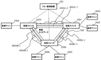
- FIG. 2 is a diagram illustrating a configuration of the overlay network system according to the first embodiment of this invention.
- a plurality of virtual switches 200A to 200C arranged as tunnel end points of the overlay network system, a flow control device 100 that controls these virtual switches 200, and these virtual switches 200 are used to communicate with each other.
- a configuration including virtual machines 300A to 300E is shown.
- VXLAN tunnels 400AB-1 to 400BC-2 which will be described later, are constructed.
- virtual switch 200 when the virtual switches 200A to 200C, the virtual machines 300A to 300E, and the VXLAN tunnels 400AB-1 to 400BC-2 are not particularly distinguished, they are referred to as “virtual switch 200”, “virtual machine 300”, and “VXLAN tunnel 400”, respectively. .
- the flow control device 100 performs flow management for constructing the VXLAN tunnel 400 in a mesh shape between the virtual switches 200, and instructs flow setting to one or more virtual switches 200. Thereby, the flow control apparatus 100 realizes a communication network between the virtual machines 300.
- Such a flow control device 100 can be realized by adding a tunnel management function to the OpenFlow controllers of Non-Patent Documents 2 and 3.
- the virtual switch 200 selects a flow entry having a matching condition that matches the input frame from the flow entries set by the instruction of the flow control apparatus 100 for the input frame from the virtual machine 300 or another virtual switch. To process the input frame.
- the virtual switch 200 outputs the input frame to the VXLAN tunnel 400 for connection with the other virtual machine 300 according to the selected flow entry, and outputs it to the other virtual switch 200 across the base network 500, or the flow control device 100. Output to or drop.
- the virtual machine 300 transmits a frame addressed to the other virtual machine 300 to the virtual switch 200 and receives a frame originating from the other virtual machine 300 from the virtual switch 200. Further, the virtual machine 300 does not need to be directly connected to the virtual switch 200 and may be connected via a layer 2 switch (L2SW), or the virtual machine 300 is a layer 3 switch (L3SW) or a router. In some cases, another virtual machine 300 is connected to the destination.
- L2SW layer 2 switch
- L3SW layer 3 switch
- another virtual machine 300 is connected to the destination.
- the virtual switch 200 and the virtual machine 300 in the connected state may be virtual entities that operate on the same virtualization server by using server virtualization technology.
- the infrastructure network 500 is a layer 3 network or the like for performing frame transfer between the virtual switches 200.
- the infrastructure network 500 can communicate with a destination IP address given when encapsulated in VXLAN, and when a multicast address is set as the destination, all virtual switches 200 It can be delivered to.
- FIG. 3 is a diagram illustrating a configuration of the virtual switch according to the first embodiment.
- the configuration includes a flow entry search unit 201, a flow entry storage unit 202, a flow entry processing unit 203, a flow processing unit 204, a flow control device communication unit 205, and a VXLAN processing unit 250. It is shown.
- the flow entry search unit 201, the flow entry storage unit 202, the flow entry processing unit 203, the flow processing unit 204, and the flow control device communication unit 205 correspond to the open flow switch function unit. Is done.
- the VXLAN processing unit 250 and the command processing unit 251 and the tunnel processing units 260-1 and 260-2 (hereinafter referred to as “tunnel processing unit 260” unless the tunnel processing units 260-1 and 260-2 are particularly distinguished). And.
- the tunnel processing unit 260 passes the VXLAN-encapsulated frame input from the VXLAN tunnel 400 to the flow entry search unit 201, and performs VXLAN decapsulation as necessary according to the instruction of the flow processing unit 204, and outputs it to the virtual machine 300.
- the tunnel processing unit 260 passes the frame input from the virtual machine 300 to the flow entry search unit 201, encapsulates VXLAN as necessary in accordance with the instruction of the flow processing unit 204, and establishes a virtual interface facing through the VXLAN tunnel 400. A process of transferring to the switch 200 is performed.
- the command processing unit 251 receives an operation from the user and outputs a UDP port number information change command or the like to the tunnel processing unit 260.
- the flow entry search unit 201 extracts flow entry search condition information for searching for a flow entry from the input frame, and searches the flow entry storage unit 203 using the flow entry search condition information. As a result of the search, the flow entry search unit 201 passes the action and input frame of the matched flow entry to the flow processing unit 204. In addition, the flow entry search unit 201 updates the time-out time and statistical information of the flow entry matched at that time, if any.
- the flow entry storage unit 202 uses a flow entry table set by the flow control device 100 and the like. The change of the flow entry in the flow entry storage unit 202 is reported to the flow control apparatus 100 and grasped. Therefore, the flow control apparatus 100 can grasp and control the behavior of the virtual switch 200.
- the flow entry processing unit 203 updates the flow entry storage unit 202 in accordance with an operation instruction or a reference instruction such as addition / deletion regarding a flow entry coming from the flow control apparatus 100 via the flow control apparatus communication unit 205. Further, the flow entry processing unit 203 refers to the flow entry storage unit 202, deletes the flow entry that has timed out, and sends the flow entry to the flow control device 100 via the flow control device communication unit 205. Report that it has been deleted.
- the flow processing unit 204 changes the value of the frame according to the input frame and its action passed from the flow control device 100 via the flow entry search unit 201 or via the flow control device communication unit 205, A frame is output or a frame is output to another virtual switch 200. Further, as necessary, the flow processing unit 204 instructs the VXLAN processing unit 250 to perform VXLAN encapsulation, outputs it to the VXLAN tunnel 400, performs VXLAN decapsulation of a frame input from the VXLAN tunnel 400, A frame is output to the flow control device 100 via the control device communication unit 205 or dropped.
- FIG. 4 is a diagram illustrating a configuration of a frame that is VXLAN encapsulated by the virtual switch according to the first embodiment of this invention.
- the tunnel processing unit 260 of the VXLAN processing unit 250 encapsulates the original frame with additional headers such as Outer MAC, Outer IP, Outer UDP, and VXLAN ID.
- additional headers such as Outer MAC, Outer IP, Outer UDP, and VXLAN ID.
- UDP port information numbers 601 and 602 described later are set in the Outer UDP header, which can be used for flow identification and load distribution (load balancing) using the same.
- decapsulation processing for removing the additional header from the encapsulated frame is performed.
- FIG. 5 is a diagram illustrating a configuration of the tunnel processing unit 260 in the virtual switch 200 according to the first embodiment. Referring to FIG. 5, a configuration including a VNI information storage unit 264, a tunnel release unit (decapsulation unit) 265, a UDP port information storage unit 266, and a tunneling unit (encapsulation unit) 267 is shown. Yes.
- the VNI information storage unit 264 holds a virtual network identifier (VNI) of VXLAN that the tunnel processing unit 260 has. This virtual network identifier (VNI) is stored in the VXLAN header of FIG.
- the tunnel release unit (decapsulation unit) 265 performs decapsulation by removing an additional header from the VXLAN frame of the frame input from the VXLAN tunnel 400.
- the UDP port information storage unit 266 holds UDP port information for the tunnel processing unit 260 to perform transmission / reception via the VXLAN tunnel 400.
- the UDP port number held in the UDP port information storage unit 266 is changed by a change command issued from the command processing unit 251.
- the UDP port information storage unit 266 can be shared by a plurality of tunnel processing units 260. That is, one UDP port number can be used for a plurality of VNIs.
- the tunneling unit (encapsulating unit) 267 When outputting to the VXLAN tunnel 400, the tunneling unit (encapsulating unit) 267 performs VXLAN encapsulation processing by adding an additional header to the original frame as shown in FIG.
- the command processing unit 251 receives an operation from the user, outputs a UDP port number information change command (UDP port number change notification) or the like to the tunnel processing unit 260, and rewrites the contents or the like of the UDP port information storage unit 266. Perform the action.
- UDP port number information change command UDP port number change notification
- the command processing unit 251 is provided to change the UDP port information storage unit 266.
- the configuration is changed by transmitting / receiving a special frame / packet for changing the UDP port number. It is also possible to perform this.
- 3 and 5 is realized by a computer program that causes a computer mounted on the virtual switch 200 to execute the above-described processes using the hardware thereof. You can also.
- FIG. 6 is a sequence diagram showing the operation of the first exemplary embodiment of the present invention.
- # 1 is set in the UDP port information storage unit 266 as a UDP port number used for VXLAN communication. Specifically, as shown in FIG. 7, at this time, only the UDP port number # 1 can receive a frame, and the UDP port number # 1 is set as the destination UDP port number at the time of frame transmission.
- the command processing unit 251 transmits a UDP port number change command (first instruction) for instructing the tunnel processing unit 260 to change the UDP port number from # 1 to # 2. (S001 in FIG. 6).
- the content of the UDP port information storage unit 266 of the tunnel processing unit 260 that has received the UDP port number change command (first instruction) is rewritten as shown in FIG. 8 (S002 in FIG. 6).
- an entry specifying UDP port number # 2 as a receivable port is added to the entry of FIG.
- the UDP port number # 2 is not the UDP port information used for the transmission destination (the transmission destination use field is NO).
- the user inputs a command for switching the transmission destination port to the new UDP port number # 2 to the virtual switch 200.
- the command processing unit 251 instructs the tunnel processing unit 260 to change the UDP port number used as the destination at the time of transmission from # 1 to # 2 (second port number switching command (second (Instruction) is transmitted (S003 in FIG. 6).
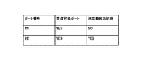
- the transmission destination use field in the UDP port information storage unit 266 of the tunnel processing unit 260 is rewritten as shown in FIG. 9 (S004 in FIG. 6).
- the transmission destination use field of the first entry in FIG. 8 is rewritten from YES to NO
- the transmission destination use field of the second entry of FIG. 8 is rewritten from NO to YES.
- This process corresponds to a process of switching from the UDP port number # 1 used for transmission destination to # 2.
- both UDP port numbers # 1 and # 2 are set as receivable UDP ports (both receivable port fields are YES).
- the user inputs a command for instructing the virtual switch 200 to open the pre-change UDP port number # 1.
- the command processing unit 251 transmits a pre-change UDP port number release command (third instruction) to the tunnel processing unit 260 (S005 in FIG. 6).
- the content of the UDP port information storage unit 266 of the tunnel processing unit 260 that has received the pre-change UDP port number release command (third instruction) is rewritten as shown in FIG. 10 (S006 in FIG. 6).
- the UDP port number # 1 is removed from the receivable UDP port of the first entry of FIG. 9 (changed from YES to NO).
- the UDP port number # 1 is released.
- the first entry is left in a state where NO is set in each field, but this entry is reused when changing from UDP port # 2 to # 1 again.
- the first entry itself may be deleted.
- the user can change the UDP port number (first instruction), the UDP port number switching command (second instruction), the pre-change UDP port number release command (third instruction).
- the switching of the UDP port number and the release of the pre-change UDP port number can be performed automatically after a lapse of a predetermined period. Further, when it is not necessary to release the pre-change UDP port number, the pre-change UDP port number release may be omitted.
- the flow control apparatus 100 on behalf of the user performs a UDP port number change command (first instruction), a UDP port number switching command (second instruction), a pre-change UDP port number release command (third instruction). Instruction) issuance instruction may be sent to the command processing unit 251. In this case, the flow control apparatus 100 can change the UDP port number with reference to a communication policy applied to the virtual machine.
- the virtual switch 200 has been described by assuming that it is connected by VXLAN, but the switch to which the present invention is applied is not limited to the virtual switch.
- some or all of the switches may be physical switches.
- the tunnel processing unit 260 passes the VXLAN-encapsulated frame input from the VXLAN tunnel 400 to the flow entry search unit 201, and in accordance with the instructions of the flow processing unit 204, In the above description, the VXLAN decapsulation is performed. However, the tunnel processing unit 260 may perform the VXLAN decapsulation and then pass the frame to the flow entry search unit 201. Similarly, when transmitting a frame received from a virtual machine, the input frame may be VXLAN encapsulated and then passed to the flow entry search unit 201.
- the flow identification information is a switch that is a UDP (User Datagram Protocol) port number.
- UDP User Datagram Protocol
- a switch comprising an OpenFlow switch function unit for processing a received frame after decapsulation and a transmission frame before encapsulation.
- a switch that receives an instruction to change the flow identification information from a control device that receives instructions regarding processing of the received frame after decapsulation and a transmission frame before encapsulation.
- Flow control apparatus 200 200A-200C Virtual switch 200a Switch 201 Flow entry search part 202 Flow entry memory
Landscapes
- Data Exchanges In Wide-Area Networks (AREA)
Abstract
La présente invention a pour objet d'améliorer une fonction de modification d'informations de paramétrage de tunnel pour un commutateur qui fonctionne comme point d'extrémité de tunnel d'un système de réseau superposé. Dans la présente invention, un commutateur qui fonctionne comme point d'extrémité de tunnel d'un système de réseau superposé comporte: une unité de traitement de tunnel qui effectue une encapsulation et désencapsulation de trames émise vers et reçues depuis le point opposé d'extrémité de tunnel; et une unité de traitement de commandes qui, suite à la réception d'une instruction de modification d'informations d'identification de flux servant à identifier une trame encapsulée, donne pour instruction à l'unité de traitement de tunnel de recevoir la trame comportant des informations d'identification de flux relatives aux états avant et après la modification, puis donne pour instruction à l'unité de traitement de tunnel de modifier les informations d'identification de flux à spécifier dans une trame en cours d'émission.
Priority Applications (1)
| Application Number | Priority Date | Filing Date | Title |
|---|---|---|---|
| JP2016538423A JPWO2016017737A1 (ja) | 2014-07-31 | 2015-07-30 | スイッチ、オーバーレイネットワークシステム、通信方法及びプログラム |
Applications Claiming Priority (2)
| Application Number | Priority Date | Filing Date | Title |
|---|---|---|---|
| JP2014-156562 | 2014-07-31 | ||
| JP2014156562 | 2014-07-31 |
Publications (1)
| Publication Number | Publication Date |
|---|---|
| WO2016017737A1 true WO2016017737A1 (fr) | 2016-02-04 |
Family
ID=55217634
Family Applications (1)
| Application Number | Title | Priority Date | Filing Date |
|---|---|---|---|
| PCT/JP2015/071611 WO2016017737A1 (fr) | 2014-07-31 | 2015-07-30 | Commutateur, système de réseau superposé, procédé de communications et programme |
Country Status (2)
| Country | Link |
|---|---|
| JP (1) | JPWO2016017737A1 (fr) |
| WO (1) | WO2016017737A1 (fr) |
Cited By (3)
| Publication number | Priority date | Publication date | Assignee | Title |
|---|---|---|---|---|
| JP2017152814A (ja) * | 2016-02-23 | 2017-08-31 | APRESIA Systems株式会社 | ネットワークシステムおよび中継装置 |
| US10938679B2 (en) | 2016-08-01 | 2021-03-02 | New H3C Technologies Co., Ltd. | Packet monitoring |
| TWI823450B (zh) * | 2022-06-29 | 2023-11-21 | 光寶科技股份有限公司 | 基站管理系統和方法 |
Citations (2)
| Publication number | Priority date | Publication date | Assignee | Title |
|---|---|---|---|---|
| JP2013005110A (ja) * | 2011-06-14 | 2013-01-07 | Ntt Communications Kk | 仮想ネットワークシステム、構成変更方法、トンネル終端装置、トンネル接続装置、及びプログラム |
| JP2013038715A (ja) * | 2011-08-10 | 2013-02-21 | Ntt Communications Kk | 仮想ネットワーク制御装置、仮想ネットワーク制御方法、仮想ネットワーク制御システム、及びプログラム |
-
2015
- 2015-07-30 JP JP2016538423A patent/JPWO2016017737A1/ja active Pending
- 2015-07-30 WO PCT/JP2015/071611 patent/WO2016017737A1/fr active Application Filing
Patent Citations (2)
| Publication number | Priority date | Publication date | Assignee | Title |
|---|---|---|---|---|
| JP2013005110A (ja) * | 2011-06-14 | 2013-01-07 | Ntt Communications Kk | 仮想ネットワークシステム、構成変更方法、トンネル終端装置、トンネル接続装置、及びプログラム |
| JP2013038715A (ja) * | 2011-08-10 | 2013-02-21 | Ntt Communications Kk | 仮想ネットワーク制御装置、仮想ネットワーク制御方法、仮想ネットワーク制御システム、及びプログラム |
Cited By (3)
| Publication number | Priority date | Publication date | Assignee | Title |
|---|---|---|---|---|
| JP2017152814A (ja) * | 2016-02-23 | 2017-08-31 | APRESIA Systems株式会社 | ネットワークシステムおよび中継装置 |
| US10938679B2 (en) | 2016-08-01 | 2021-03-02 | New H3C Technologies Co., Ltd. | Packet monitoring |
| TWI823450B (zh) * | 2022-06-29 | 2023-11-21 | 光寶科技股份有限公司 | 基站管理系統和方法 |
Also Published As
| Publication number | Publication date |
|---|---|
| JPWO2016017737A1 (ja) | 2017-05-18 |
Similar Documents
| Publication | Publication Date | Title |
|---|---|---|
| JP5991424B2 (ja) | パケット書換装置、制御装置、通信システム、パケット送信方法及びプログラム | |
| US10541920B2 (en) | Communication system, communication device, controller, and method and program for controlling forwarding path of packet flow | |
| US9894003B2 (en) | Method, apparatus and system for processing data packet | |
| JP5644895B2 (ja) | 通信システム、制御装置、通信方法及びプログラム | |
| JP5494668B2 (ja) | 情報システム、制御サーバ、仮想ネットワーク管理方法およびプログラム | |
| KR101755138B1 (ko) | 통신 시스템, 제어 장치, 및 네트워크 토폴로지 관리 방법 | |
| JP5994851B2 (ja) | 転送装置の制御装置、転送装置の制御方法、通信システムおよびプログラム | |
| EP3228054A1 (fr) | Chaînage de fonctions de service inter-domaines | |
| JP5987841B2 (ja) | 通信システム、制御装置、転送ノード、通信システムの制御方法およびプログラム | |
| WO2014106945A1 (fr) | Dispositif de commande, système de communication, procédé et programme de commande d'extrémité de tunnel | |
| WO2014112616A1 (fr) | Appareil de commande, appareil de communication, système de communication, procédé et logiciel de commande de commutateur | |
| JP6007972B2 (ja) | 通信ノード、パケット処理方法及びプログラム | |
| JP6525256B2 (ja) | 仮想ネットワークシステムおよび仮想ネットワーク経路設定方法 | |
| WO2016017737A1 (fr) | Commutateur, système de réseau superposé, procédé de communications et programme | |
| US20170359259A1 (en) | Packet field matching in openflow | |
| EP2924925A1 (fr) | Système de communication, dispositif de gestion de réseau virtuel, noeud de communication, et procédé et programme de communication | |
| JP5991385B2 (ja) | 制御情報管理装置、制御情報提示方法及びプログラム | |
| JP6052284B2 (ja) | 通信装置、制御装置、通信システム、通信方法、通信装置の制御方法及びプログラム | |
| WO2014065315A1 (fr) | Système de communication, serveur de machine virtuelle, dispositif de gestion de réseau virtuel, procédé de commande de réseau et programme | |
| KR101812856B1 (ko) | 스위치 장치, vlan 설정 관리 방법, 및 컴퓨터 판독가능 저장매체 | |
| JP6127569B2 (ja) | スイッチ、制御装置、通信システム、制御チャネルの管理方法及びプログラム | |
| KR102024545B1 (ko) | 오버레이 네트워크 기반에서의 오리지널 패킷 플로우 매핑 장치 및 그 방법 | |
| WO2016031923A1 (fr) | Commutateur, système de réseau superposé, procédé et programme de changement de configuration de tunnel | |
| JP6128132B2 (ja) | 通信装置、制御装置、通信システム、パケット処理方法、通信装置の制御方法及びプログラム | |
| WO2014119602A1 (fr) | Appareil de commande, commutateur, système de communication, procédé de commande de commutateur et programme |
Legal Events
| Date | Code | Title | Description |
|---|---|---|---|
| 121 | Ep: the epo has been informed by wipo that ep was designated in this application |
Ref document number: 15826946 Country of ref document: EP Kind code of ref document: A1 |
|
| ENP | Entry into the national phase |
Ref document number: 2016538423 Country of ref document: JP Kind code of ref document: A |
|
| NENP | Non-entry into the national phase |
Ref country code: DE |
|
| 122 | Ep: pct application non-entry in european phase |
Ref document number: 15826946 Country of ref document: EP Kind code of ref document: A1 |