WO2014112616A1 - Appareil de commande, appareil de communication, système de communication, procédé et logiciel de commande de commutateur - Google Patents
Appareil de commande, appareil de communication, système de communication, procédé et logiciel de commande de commutateur Download PDFInfo
- Publication number
- WO2014112616A1 WO2014112616A1 PCT/JP2014/050923 JP2014050923W WO2014112616A1 WO 2014112616 A1 WO2014112616 A1 WO 2014112616A1 JP 2014050923 W JP2014050923 W JP 2014050923W WO 2014112616 A1 WO2014112616 A1 WO 2014112616A1
- Authority
- WO
- WIPO (PCT)
- Prior art keywords
- entry
- switch
- packet
- condition
- control device
- Prior art date
Links
Images


Classifications
-
- H—ELECTRICITY
- H04—ELECTRIC COMMUNICATION TECHNIQUE
- H04L—TRANSMISSION OF DIGITAL INFORMATION, e.g. TELEGRAPHIC COMMUNICATION
- H04L45/00—Routing or path finding of packets in data switching networks
- H04L45/74—Address processing for routing
- H04L45/745—Address table lookup; Address filtering
-
- H—ELECTRICITY
- H04—ELECTRIC COMMUNICATION TECHNIQUE
- H04L—TRANSMISSION OF DIGITAL INFORMATION, e.g. TELEGRAPHIC COMMUNICATION
- H04L47/00—Traffic control in data switching networks
- H04L47/10—Flow control; Congestion control
-
- H—ELECTRICITY
- H04—ELECTRIC COMMUNICATION TECHNIQUE
- H04L—TRANSMISSION OF DIGITAL INFORMATION, e.g. TELEGRAPHIC COMMUNICATION
- H04L69/00—Network arrangements, protocols or services independent of the application payload and not provided for in the other groups of this subclass
- H04L69/22—Parsing or analysis of headers
Definitions
- the present invention is based on a Japanese patent application: Japanese Patent Application No. 2013-008835 (filed on January 21, 2013), and the entire contents of this application are incorporated in the present specification by reference.
- the present invention relates to a control device, a communication device, a communication system, a switch control method, and a program, and more particularly, to a control device, a communication system, a switch control method, and a program for centralized control of switches arranged in a network.
- Non-Patent Documents 1 and 2 OpenFlow captures communication as an end-to-end flow and performs path control, failure recovery, load balancing, and optimization on a per-flow basis.
- the OpenFlow switch specified in Non-Patent Document 2 includes a secure channel for communication with the OpenFlow controller, and operates according to a flow table that is appropriately added or rewritten from the OpenFlow controller. For each flow, a set of match conditions (Match Fields), flow statistical information (Counters), and instructions (Instructions) that define processing contents are defined for each flow (non-patented). (Refer to “4.1 Flow Table” in Document 2).
- the OpenFlow switch searches the flow table for an entry having a matching condition (see “4.3 Match Fields” in Non-Patent Document 2) that matches the header information of the received packet. If an entry that matches the received packet is found as a result of the search, the OpenFlow switch updates the flow statistical information (counter) and processes the processing (designated) in the instruction field of the entry for the received packet. Perform packet transmission, flooding, discard, etc. from the port. On the other hand, if no entry that matches the received packet is found as a result of the search, the OpenFlow switch requests the OpenFlow controller to set an entry, that is, determines the processing content of the received packet, via the secure channel. A request (Packet-In message) is transmitted. The OpenFlow switch receives a flow entry whose processing content is defined and updates the flow table. In this way, the OpenFlow switch performs packet transfer using the entry stored in the flow table as a processing rule.
- a matching condition see “4.3 Match Fields” in Non-Patent Document 2
- the OpenFlow switch updates the flow statistical
- Non-Patent Document 2 In OpenFlow Specification Version 1.1.0 of Non-Patent Document 2, a plurality of instructions (Go-to Table) for instructing transition to another flow table are set as processing contents (Instruction). Pipeline processing for executing a plurality of processing contents can also be performed using a flow table (see “4.1.1 Pipeline Processing” in Non-Patent Document 2).
- Non-Patent Document 2 describes that a packet is processed using a plurality of flow tables as described above. However, as described above, after using a pipeline process to rewrite a packet header with an entry in a certain flow table, the next flow table searches for the corresponding entry in the rewritten header. However, the specific usage of the plurality of flow tables is not described.
- Non-Patent Document 1 discloses the description about the open flow switch as described above, but does not describe that the switch has a plurality of flow tables.
- An object of the present invention is to provide a control device, a communication device, a communication system, a switch control method, and a program that can contribute to reducing the management burden of entries set in a centralized control network switch.
- a control apparatus for setting an entry including a rule for processing a packet in a switch, wherein a first table for filtering a received packet of the switch in a first table provided in the switch And a control device for setting a second entry including a rule for processing a packet selected by the first entry among the received packets in a second table included in the switch.
- a communication device that receives an entry including a rule for processing a packet from a control device, and processes the packet according to the entry, for filtering a received packet of the communication device.
- a first table for storing a first entry; and a second table for storing a second entry including a rule for processing a packet selected by the first entry among the received packets.
- a communication device is provided.
- a first table for storing a first entry for filtering received packets, and a packet selected by the first entry among the received packets are processed.
- a second table for storing a second entry including the rule of the communication, and receiving the entry stored in the first and second tables from the control device, and processing the packet according to the entry A first entry for filtering received packets of the switch in a first table included in the device and the switch, and the first table out of the received packets in a second table provided in the switch.
- a control device for setting a second entry including a rule for processing a packet selected by the first entry. Temu is provided.
- a control device that sets an entry including a rule for processing a packet in a switch has a first table for filtering received packets of the switch in a first table included in the switch.
- a method for controlling a switch is provided. The method is tied to a specific machine, the control device that controls the switch.
- a first entry for filtering received packets of the switch in a first table provided in the switch in a computer that sets an entry including rules for processing the packet in the switch
- Setting a second entry including a rule for processing a packet selected by the first entry among the received packets in a second table included in the switch
- This program can be recorded on a computer-readable (non-transient) storage medium. That is, the present invention can be embodied as a computer program product.
- FIG. 5 is a diagram illustrating an entry setting example when one table is used in the switch according to the first embodiment of this invention. It is the figure which showed the example of the table of the 1st Embodiment of this invention. It is a figure showing the structure of the communication system of the 2nd Embodiment of this invention. It is a figure which shows the detailed structure of the switch of the 2nd Embodiment of this invention. It is a functional block diagram which shows the detailed structure of the control apparatus of the 2nd Embodiment of this invention.
- FIG. 13 It is a figure for demonstrating the operation content of the 2nd table by the access policy of FIG. 13 is an example of virtual network configuration information updated by connection of a switch 200B in FIG. It is a figure for demonstrating the operation content of the 1st table by connection of switch 200B of FIG. It is a figure for demonstrating the operation content of the 3rd table by connection of switch 200B of FIG. It is a figure for demonstrating operation
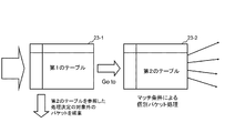
- a switch 20 that processes received packets with reference to a plurality of tables, a first table 23-1 that filters received packets, and a first table 23- 1 is applicable to a communication system having a control device including a switch control unit that holds a second table 23-2 that processes packets selected by 1.
- Each of the switches 20 may be a physical switch, but may be a virtual switch that operates on an apparatus such as a server.
- the switch 20 may be a virtual switch that virtually operates on a terminal such as a mobile phone or a smartphone.
- the first table 23-1 includes an entry in which a matching condition for specifying a packet to be filtered and processing contents such as discard are associated with each other, a matching condition for specifying other packets, An entry that associates processing contents instructed to be processed with reference to the table 23-2 is set.
- the switch 20 refers to the first table 23-1, for example, a packet to be processed by referring to the second table 23-2, and An operation of selecting other packets is performed. Then, the switch 20 refers to the second table 23-2, obtains a process to be applied to the selected packet, and executes a transfer process or the like.
- Examples of filtering performed using the first table 23-1 include, for example, discarding packets that cause loops, abnormal packets, etc., communication between specific hosts, specific packets, etc. For example, access control is performed. In addition to discarding, processing applied to these packets may be redirected to a predetermined destination.
- FIG. 2 an example in which there is one first table 23-1, but a plurality of tables corresponding to the first table 23-1 are prepared, and each table is used, You may make it filter from a different viewpoint.
- FIG. 3 is a diagram illustrating a configuration of the communication system according to the first embodiment.
- the present invention can be realized by a control device that controls a plurality of switches 20A and 20B to realize communication between a terminal and a server.
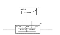
- FIG. 4 is a diagram showing a detailed configuration of the switches 20A and 20B (hereinafter referred to as “switch 20” when the switches 20A and 20B are not particularly distinguished).
- switch 20 a configuration including a control message transmission / reception unit 21, a packet processing unit 22, and a table 23 is shown.
- table 23 when the first table and the second table are not distinguished, they are also referred to as “table 23”.
- the control message transmission / reception unit 21 receives a control message related to the operation of the table from the control device 100 and updates the table. In addition, the control message transmission / reception unit 21 executes an operation according to a transmission request for an entry registered in the table 23 to the control device 100 and a packet output instruction from the control device 100.
- the packet processing unit 22 When the packet processing unit 22 receives a packet, the packet processing unit 22 refers to the table 23, searches for an entry having a matching condition that matches the received packet, and executes an operation defined for the corresponding entry.
- the table 23 includes a first table and a second table as described above.
- FIG. 5 shows a configuration example of the table 23.
- a policy is applied in which communication is permitted for a packet whose match condition is “A” and filtering is performed for a packet whose match condition is “B”.
- a process for referring to the second table for a packet with a matching condition of “A” is set.
- a process for discarding a packet with a matching condition “B” is set.
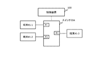
- FIG. 6 is a diagram illustrating the configuration of the control device 100C according to the first embodiment.
- the control device 100C includes a filtering policy management unit 111, a processing determination unit 113, two table operation units 114 and 115, and a switch communication unit 107, and is configured to control the switch 20.
- two table operation units are provided, but a plurality of table operation units may be provided in the control device 100C instead of a plurality.
- the filtering policy management unit 111 manages a policy for filtering packets received by the switch.
- the policy include a policy for discarding an abnormal packet such as a loop packet from a host, a policy for access control for discarding a packet from a specific host, and the like. It is done.
- the table operation unit 114 creates an entry to be set in the first table 23-1 of the switch 20 with reference to the policy managed by the filtering policy management unit 111, and the switch 20 via the switch communication unit 107. Send to.
- the process determining unit 113 determines a process to be applied to the packet selected by the filtering entry generated by the table operating unit 114.
- the other table operation unit 115 creates an entry in the second table 23-2 for causing the switch 20 to execute the process determined by the process determination unit 113, and switches the switch via the switch communication unit 107. 20 to send.
- the switch 20 in FIG. 6 has the configuration shown in FIG. 4, receives a control message related to the operation of the table from the control device 100, and updates the tables 23-1 and 23-2. In addition, the switch 20 executes an operation according to a transmission request for an entry registered in the tables 23-1 and 23-2 with respect to the control device 100 and a packet output instruction from the control device 100. Then, when receiving the packet, the switch 20 refers to the tables 23-1 and 23-2, searches for an entry having a matching condition that matches the received packet, and executes the operation defined for the corresponding entry. For example, when the switch 20 receives a packet that matches the matching condition “A”, the switch 20 refers to the second table and determines the process. For example, when the switch 20 receives a packet that matches the match condition “B”, the switch 20 performs an operation of discarding the packet.
- FIG. 7 is a diagram illustrating the configuration of the control device 100D.
- the control device 100D includes a first filtering policy management unit 121, a second filtering policy management unit 122, a processing determination unit 113, three table operation units 124, 125, and 126, and a switch communication unit 107.
- the switch 20 includes three tables, a first table 23-1, a second table 23-2, and a third table 23-3.
- the switch 20 has a plurality of tables for performing filtering.
- the first table 23-1 is used for filtering received packets, but a plurality of tables for performing filtering can be provided.
- the first table 23-1 and the second table 23-2 are used as tables for performing filtering from different viewpoints.
- a filtering policy determined by the first filtering policy management unit 121 is set in the first table 23-1.
- the second filtering policy set by the second filtering policy management unit 122 is set in the second table 23-2.
- the first filtering policy and the second filtering policy may be filtering policies from different viewpoints.
- the setting method of the first table, the second table, and the third table will be described with reference to FIG.
- a policy for discarding a packet whose match condition is “C” is set.
- an entry associated with the processing content for referring to the second table is set for packets with matching conditions “A” and “B”.
- a policy for discarding a packet whose match condition is “B” is set.
- an entry is set that associates the processing contents of forwarding from port # 2 for a packet whose match condition is “A” that was not discarded in the first table and the second table. .
- the first filtering policy management unit 121 manages a filtering policy for creating an entry to be set in the first table 23-1 of the switch 20, for example.
- the second filtering policy management unit 122 manages a filtering policy for creating an entry to be set in the second table 23-2 of the switch 20.
- the filtering policy set in the first table 23-1 and the filtering policy set in the second table 23-2 may be based on different viewpoints. Similar to FIG.
- the process determining unit 113 determines a process to be applied to packets selected by the filtering entries generated by the table operating units 114 and 115. Further, like the table operation units 114 and 115 in FIG. 6, the number of table operation units included in the control device 100 ⁇ / b> D in FIG. 7 may not be three.
- the switch is provided with a table for filtering received packets and a table for performing packet processing after filtering. Therefore, it is possible to perform filtering on packets received by the switch using a plurality of tables.
- the number of entries set in the switch can be reduced as compared with the case where both filtering of received packets and processing for received packets are performed with one table.
- the system of FIG. 9 shows a configuration in which terminal # 1-1, terminal # 1-2, and terminal # 1-3 are connected to switch 20A.
- the terminals # 1-1, # 1-2, and # 1-3 are assumed to belong to the terminal group “A”.
- the terminal group A for example, a part of the IP address of each terminal is assumed to be common.
- the terminal # 1-1 is connected to the port # 1 of the switch 20A
- the terminal # 1-2 is connected to the port # 2
- the terminal # 1-3 is connected to the port # 3.
- FIG. 10 shows a configuration example of a table when the above filtering policy is applied to one table.
- the terminal # 1-1 as in the second and third entries, a process for transferring packets from the corresponding ports to candidate destinations # 1-2 and # 1-3, respectively. The contents are associated.
- a loop is generated, so that the processing content for discarding the packet is set.
- the processing content of discarding the packet regardless of the destination is associated with a packet whose source is the terminal # 1-2 that restricts communication.
- “*” indicates a wild card.
- the address having terminal # 1-2 as the transmission source is the match condition, and no specific value is specified for the destination address.
- the source address of the received packet is the address of terminal # 1-2, the received packet matches the entry regardless of the destination.
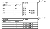
- FIG. 11 shows a configuration example of each table when the above-described filtering policy is applied using two tables.
- the first and second entries of the first table are entries for discarding a packet that causes a loop as described above.
- the processing contents for referring to the second table are associated with the packets whose transmission sources are terminals # 1-1 and # 1-3 that allow communication.
- the fifth entry of the first table describes the processing content of discarding a packet whose source is any of group A including terminals # 1-1 to # 1-3. Note that this entry match condition includes terminals # 1-1 and # 1-3 that allow communication, but packets corresponding to source addresses # 1-1 and # 1-3 are stored in the first table. Are matched with the match condition of any one of the first to fourth entries. Therefore, packets originating from terminals # 1-1 and # 1-3 are not discarded at the fifth entry.
- the second table of FIG. 11 describes the processing content of transferring a packet from each corresponding port according to the destination address.
- a process for transferring a packet from a port corresponding to the destination address of the packet is set regardless of the transmission source.
- the processing contents can be set in consideration of only the destination without depending on the transmission source. .
- the packet processed in the second table is a packet that has already been filtered. In the above example, the packet from terminal # 1-2 whose access is to be denied is not processed in the second table.
- the processing content can be described using only the destination address as the match condition without specifying the source address.
- the source address can be set to “*”.
- the entries set as many as the number of source addresses are displayed. Can be compressed into one entry.
- the match conditions of the second and sixth entries are both destination addresses # 1-2, but the source addresses are different. These entries can be compressed into one second entry in the second table of FIG. Therefore, the number of entries can be reduced by performing filtering with a plurality of tables as in the present invention.
- the number of entries to be set in the table in this embodiment is reduced as compared with the case of using one table. Further, as the number of terminals increases, the number of combinations of transmission sources and destinations increases, so the effect of reducing the number of entries according to the present embodiment becomes more remarkable.
- the communication amount for setting entries from the control device to the switch can also be reduced. It becomes possible. Therefore, according to the present embodiment, it is possible to reduce the load on the control device.
- FIG. 12 is a diagram showing a configuration of a communication system according to the second exemplary embodiment of the present invention.
- VM virtual machine
- # 1-1 # that communicates with the control device 100 that controls the network (NW) and the switches 200A and 200B via the switches 200A and 200B.
- # 2-1 # 2-1
- TEP end point
- a virtual tunnel is a path constructed virtually or logically on a network.
- the switch 200A has three ports # 1 to # 3.
- the VM # 1-1 is connected to the port # 1, and the VM # 1-2 is connected to the port # 2.
- the port # 3 of the switch 200A is connected to the TEP 400, and packets received from the VM # 1-1 and VM # 1-2 can be transmitted to the switch 200B via the virtual tunnel.
- the switch 200B has two ports # 1 and # 2.
- the VM # 2-1 is connected to the port # 1, and the TEP 400 is connected to the port # 2.
- the switches 200A and 200B may be physical switches, but may be virtual switches that operate on the virtualization server on which the VMs # 1-1, # 1-2, and # 2-1 operate.
- the switches 200A and 200B may be virtual switches that virtually operate on a terminal such as a mobile phone or a smartphone.
- FIG. 13 is a diagram showing a detailed configuration of the switches 200A and 200B (hereinafter referred to as “switch 200” when the switches 200A and 200B are not particularly distinguished).
- switch 200 a configuration including a control message transmission / reception unit 21, a packet processing unit 22, and a table 23 is shown.
- the control message transmission / reception unit 21 receives a control message regarding the operation of the table 23 from the control device 100, and updates the table 23. In addition, the control message transmission / reception unit 21 executes an operation according to a transmission request for an entry registered in the table 23 to the control device 100 and a packet output instruction from the control device 100.
- the packet processing unit 22 When the packet processing unit 22 receives the packet, the packet processing unit 22 refers to the table 23, searches for an entry having a matching condition that matches the received packet, and executes an operation (action) determined for the corresponding entry.
- the table 23 is composed of N tables assigned numbers # 0 to #N that function as a reference order.
- the switch 200 is described as having three tables # 0 to # 2, but there is no restriction on the number of tables.
- a configuration in which a plurality of first to third tables to be described later are provided can be employed.
- the packet processing unit 22 when receiving the packet, the packet processing unit 22 searches the table # 0 for entries having matching conditions that match the received packet in order. As a result of the search, when there is no entry having a matching condition that matches the received packet in all the tables, the packet processing unit 22 requests the control message transmitting / receiving unit 21 to transmit an entry transmission request to the control device 100. Note that an entry having an action (action) that defines an inquiry to the control device 100 can be set in the table 23. On the other hand, when there is an entry having a matching condition that matches the received packet in any of the tables # 0, the packet processing unit 22 performs an operation (action) determined for the corresponding entry.
- action an operation
- Such a switch can be realized by, for example, an open flow switch conforming to the specification of Non-Patent Document 2.
- the TEP 400 is a device that performs encapsulation and decapsulation of packets to be transmitted and received according to a predetermined tunnel protocol.
- the TEP 400 can be configured by a switch that can be controlled from the control device 100.
- the predetermined tunnel protocol include GRE (Generic Routing Encapsulation), NVGRE (Network Virtualization using GRE), and IPsec (Security Architecture for Internet Protocol).
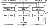
- FIG. 14 is a diagram showing a detailed configuration of the control device 100.
- a virtual network configuration management unit 101 that holds a configuration of a virtual network
- an access policy management unit 102 that holds an access policy that associates the characteristics of communication for performing access control with communication availability
- a switch A configuration including a process determining unit 103 that determines a process to be executed by 200A and 200B, and first to third table operating units 104 to 106 is shown.
- a portion 109 indicated by a broken line in FIG. 14 corresponds to the switch control unit 19 in FIG.
- FIG. 15 is an example of virtual network configuration information held in the virtual network configuration management unit 101 of the control device 100.
- the virtual network configuration management unit 101 is not limited to the content shown in FIG.
- the first table operation unit 104 determines, from the virtual network configuration information held in the virtual network configuration management unit 101, a packet to be processed by referring to a table after the second table (table # 1) of the switch 200. Create an entry to screen. For example, the first table operation unit 104 generates an entry for discarding a packet that generates a loop destined for the same host from a specific host included in the virtual network. More specifically, when a packet destined to the MAC address of the port (that is, an abnormal packet destined to its own address) is received from the port # 1 or # 2, the packet is discarded (Drop). Create an entry that indicates Thereafter, the first table operation unit 104 transmits to the switch 200 together with a control message instructing storage in the first table (table # 0) of the switch 200.
- FIG. 16 shows an example of an entry generated from the virtual network configuration information shown in FIG. 15 by the first table operation unit 104 and set in the first table (table # 0) of the switch 200A in FIG.
- the third entry from the top in FIG. 16 is an entry that determines a hit and indicates a jump to table # 1 (Go to) when a packet other than the first and second entries is received (note that Hereinafter, the symbol “*” in the table represents a wild card.) Note that the priority field in FIG.
- 16 indicates the priority of each entry, and is referred to, for example, when selecting an entry to be applied when a packet matches a match condition of a plurality of entries.
- the input port and the destination MAC address are used for the match condition, but other header information may be used.
- the entries shown in FIG. 16 are merely examples. For example, there is a possibility that the information in the packet header clearly shows an abnormal value or is used for a DoS (Deny of Service) attack. An entry for capturing and discarding a packet or the like may be set.
- the second table operation unit 105 generates an entry for performing filtering on a packet flowing through the virtual network based on the access policy held in the access policy management unit 102. Then, the second table operation unit 105 transmits to the switch 200 together with a control message instructing to store the generated entry in the second table (table # 1) of the switch 200.
- FIG. 17 is an example of entries set in the second table (table # 1) of the switch 200A in FIG. 12 by the second table operation unit 105 in the initial state.
- the first entry from the top of FIG. 17 indicates that the source MAC address from port # 1 is AA: AA: AA: AA: AA: AA as the destination MAC address from 00: 00: 00: 01: 00: 01.
- the entry is an instruction to drop the packet.
- Such an entry has an access policy such as prohibiting access from a VM having a MAC address of 00: 00: 00: 01: 00: 01 to a VM having a MAC address of AA: AA: AA: AA: AA.
- an access policy such as prohibiting access from a VM having a MAC address of 00: 00: 00: 01 to a VM having a MAC address of AA: AA: AA: AA: AA.
- the process determining unit 103 calculates an end-to-end route based on the topology of the virtual network including the switches 200A and 200B. Further, the process determining unit 103 determines a process to be executed by the switches 200A and 200B such as header rewriting as necessary.
- the third table operation unit 106 Based on the path information obtained from the processing determination unit 103, the third table operation unit 106 generates an entry that causes the switch 200 to perform transfer of received packets and header conversion, and to the switch 200, the switch 200 It is transmitted together with a control message instructing storage in the third table (table # 2).
- FIG. 18 is an example of entries set in the third table (table # 2) of the switch 200A in FIG. 12 by the third table operation unit 106.
- the first entry from the top in FIG. 18 indicates that a packet in which the MAC address of the port # 2 to which the VM # 1-2 is connected is set as the destination address is output from the port # 2. .
- the second entry from the top in FIG. 18 indicates that a packet in which the MAC address of the port # 1 connected to the VM # 1-1 is set as the destination MAC address is output from the port # 1. ing.
- the two entries enable communication between the VMs # 1-1 and # 1-2 via the switch 200A.
- the first table operation unit 104 to the third table operation unit 106 are described as independent processing units for the sake of explanation, but the filtering table (the first table (table # 0) and the second table (corresponding to the table # 1)) and the table for determining the process to be applied to the packet (corresponding to the third table (table # 2)) can be updated.
- the first table operation unit 104 to the third table operation unit 106 can be appropriately integrated.
- a single table operation unit that executes all the processes of the first table operation unit 104 to the third table operation unit 106 may be provided.
- Each part (processing means) of the control device shown in FIG. 14 is realized by a storage means mounted on a computer constituting the control device and a computer program that executes the above-described processes using the hardware. You can also.
- control device 100 First, an operation when an access policy is added to the access policy management unit 102 will be described.
- FIG. 19 is an example of an access policy added to the access policy management unit 102 of the control device 100.
- FIG. 19 is merely an example.
- an access policy that allows only a packet addressed to a specific VM from a specific VM or an access policy that allows only a packet related to a specific service to pass can be set.
- the second table operation unit 105 Based on the access policy, the second table operation unit 105 generates an entry for performing filtering on a packet flowing through the virtual network, and stores the entry in the second table (table # 1) of the switch 200 for the switch 200. This message is sent with a control message indicating that
- FIG. 20 is an example of an entry generated from the access policy shown in FIG. 19 by the second table operation unit 105 and added to the second table (table # 1) of the switch 200A in FIG.
- the second table (table # 1) of the switch 200A in FIG. 20
- from the port # 1 to the VM among the packets that are determined to be a process decision target with reference to the table after the second table (table # 1) of the switch 200 in the first table If a connection port of # 1-1 is set as the source MAC address, a connection port of VM # 1-2 is set as the destination MAC address, and the upper protocol is IPv6, the packet is discarded (Drop) An entry for instructing to do so has been added.
- “Drop” is specified as an action. However, depending on the access policy, for example, rewriting the header or setting an entry instructing redirection to a specific destination is set. Also good.
- FIG. 21 shows virtual network configuration information after the addition of port # 1 of the switch 200B.
- the third entry an entry that associates the ID of the switch 200B, the port number # 1 to which the VM # 2-1 is connected, and the MAC address assigned to the port is added. Has been.
- the first table operation unit 104 When detecting the change in the virtual network configuration information, the first table operation unit 104 starts the operation of the first table (table # 0) of the switch 200 based on the changed virtual network configuration information.
- FIG. 22 is a diagram showing the contents of the first table (table # 0) of the switch 200A operated by the first table operation unit 104 based on the virtual network configuration information shown in FIG.
- the packet is discarded (Drop) ) Is added (see the third entry from the top in FIG. 22).
- FIG. 23 is a diagram showing the contents of the third table (table # 2) of the switch 200A operated by the third table operation unit 106 based on the virtual network configuration information shown in FIG.
- Table # 2 As a destination address among packets determined to be a process determination target with reference to the table after the third table (table # 2) of the switch 200 in the first and second tables.
- An entry for instructing that a packet in which the MAC address of the port # 1 to which the VM # 2-1 of the switch 200B is connected is set is output from the port # 3 is added (third from the top in FIG. 23). See entry).
- packet transmission from the VM # 1-1, # 1-2 to the VM # 2-1 becomes possible.
- an entry for instructing to perform flooding in which a packet that does not match the above three entries is transmitted from a port other than the reception port is added (see the sixth entry from the top in FIG. 23). ).
- an entry for transferring a packet to the switch 200A side according to the destination MAC address is set in the switch 200B in the same manner after filtering abnormal packets and the like.
- the first table (Table # 0) to the third table (Table # 2) are set in the switch 200 as shown in FIG.
- the switch 200 searches the second table (Table # 1) 230-1 after the first table (Table # 0) 230-0.
- the switch 200 performs access control according to the content (Drop or the like if hit).
- the switch 200 searches the third table (Table # 2) 230-2, and finally outputs the packet from the port connected to the corresponding virtual network (see FIG. 25).
- the control device 100 may be requested to transmit an entry corresponding to the received packet.
- the switch 200 there may be a case where an entry for executing an entry transmission request to the control device 100 is set with a low priority. In this case, the switch 200 discards the abnormal packet among the received packets according to the entry having the higher priority in the first table (Table # 0), and among the remaining received packets, the second table (Table #). 1) An entry transmission request is transmitted to the control apparatus 100 only for packets that do not hit any of the entries in the third table (Table # 2).
- the switch 200 transmits an entry transmission request for processing an abnormal packet, and the control device 100 does not need to respond to the request. For this reason, the amount of communication performed between the switch 200 and the control device 100, such as an entry transmission request from the switch 200 and a response from the control device 100 to the request, is reduced, so that the load on the control device 100 and the switch 200 is reduced. Is reduced.
- the switch is provided with a table for filtering received packets and a table for performing packet processing after filtering. Therefore, similarly to the first embodiment, it is possible to perform filtering on packets received by the switch using a plurality of tables.
- the number of entries to be set in the switch can be set as compared with the case where both filtering of received packets and processing for received packets are performed with one table. Can be reduced.
- first table (Table # 0) 230-0 to third table (Table # 2) 230-2 on the switch 200 side are used, and two of them (first table).
- first table Table # 0
- second table Table # 1
- the first table operation unit 104 and the second table operation unit 105 operate one table (for filtering) on the switch 200 side
- the third table operation unit 106 selects another table on the switch 200 side (process determination).
- the first table operation unit 104 to the third table operation unit 106 may be configured to operate a plurality of tables of the switch 200, respectively.
- a third embodiment it is possible to set a process to be performed by a specific host (VM) in addition to the filtering of received packets in the preceding table among a plurality of tables.
- VM virtual network ID
- the virtual network ID “1” is used together with the process of referring the VM # 1-1 to the next table in the previous table.
- the table in the previous stage is used to determine whether or not the user belongs to a virtual network and the information is used for matching.
- the third embodiment of the present invention can be implemented with substantially the same configuration as the second embodiment of the present invention, and therefore will be described with a focus on differences from the second embodiment.
- 26 is generated from the virtual network configuration information shown in FIG. 15 by the first table operation unit 104 according to the third embodiment of this invention, and set in the first table (table # 0) of the switch 200A in FIG. It is an example of the entry to be done.
- the difference from the first embodiment and the second embodiment is that the ID of the virtual network to which the received packet belongs is set in the first table (table # 0), and the next table # 1 is referred to. That is, the processing content for instructing this is set. For example, in the first and second entries from the top in FIG.
- the meta information storage register (reg0) used as a storage area for the virtual network ID After setting the virtual network ID “1”, an action for instructing to jump (Go to) to table # 1 is set.
- the third entry from the top in FIG. 26 is an entry instructing to drop (drop) the other packet (that is, a packet that does not belong to any virtual network).
- the packet processing unit 22 processes a packet with reference to each table, the virtual network ID to which the packet being processed belongs can be recognized by referring to the contents of the meta information storage register.
- FIG. 27 is an example of entries set in the second table (table # 1) of the switch 200A in FIG. 12 by the second table operation unit 105 according to the third embodiment of the present invention.
- the difference from the entry shown in FIG. 17 is that the meta information storage register (reg0) can be set in the match condition.
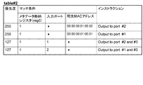
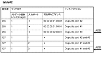
- FIG. 28 is an example of entries set in the third table (table # 2) of the switch 200A in FIG. 12 by the third table operation unit 106 according to the third embodiment of this invention.
- the meta information storage register (reg0) is used for the match condition.
- the second entries enable communication between the VMs # 1-1 and # 1-2 via the switch 200A.
- FIG. 29 is a diagram showing the contents of the first table (table # 0) of the switch 200A operated by the first table operation unit 104 based on the virtual network configuration information shown in FIG.
- the virtual network ID “1” is set in the meta information storage register (reg0), and then jump to the table # 1 (Go to) An entry in which an action for instructing to be set is added (see the third entry from the top in FIG. 29).
- the first table (Table # 0) to the third table (Table # 2) are set in the switch 200 as shown in FIG.
- the switch 200 receives a packet belonging to an appropriate virtual network
- the switch 200 sets the ID of the virtual network in the metadata (reg0) according to the corresponding entry of the first table (Table # 0) 230-0
- the table (Table # 1) 230-1 and the third table (Table # 2) 230-2 are searched.
- the switch 200 outputs the packet from a port connected to the corresponding virtual network (see FIG. 32).
- the switch is provided with a table for filtering received packets and a table for performing packet processing after filtering. Therefore, similarly to the first embodiment and the second embodiment, it is possible to perform filtering on packets received by the switch using a plurality of tables.
- the switch is compared with a case where both filtering of received packets and processing for received packets are performed with one table.
- the number of entries set in can be reduced.
- the example in which the virtual network ID “1” is assigned when the first table (Table # 0) is determined to belong to the virtual network has been described.
- the virtual network ID can be used as a matching condition to apply different processing for each virtual network, for example, using the second table (Table # 1), a different access policy can be set for each virtual network ID. It can also be applied or further filtered, as well as the third table (Table 2) using, it is possible to forward packets along the path corresponding to the configuration of the virtual network ID.
- control devices 100, 100C, and 100D include the processing determination unit 103, but the processing determination unit 103 may be included in another device. Further, instead of the processing determination unit 103, a configuration may be provided in which a storage unit that stores pre-calculated route information and entries to be set in the switch is provided.
- the metadata (reg0) of Non-Patent Document 2 is used as an area for recording information (virtual network ID) for identifying a virtual network to which a packet that matches the matching condition belongs.
- region for example, VLAN ID
- the process determining unit 103 calculates an end-to-end route based on topology information. However, the process determining unit 103 calculates a route considering virtual network configuration information and an access policy. May be performed.
- any one of the first to third forms The control apparatus according to claim 2, wherein the second entry includes a condition in which information corresponding to a transmission source address of the received packet is set as a wild card.
- the first table an entry for selecting a packet to be processed by referring to the second table and a packet to be excluded from the process determined by referring to the second table are set.
- Table operation section A control apparatus comprising: a second table operation unit configured to set an entry defining a process to be applied to the selected packet based on the packet selected by the first table in the second table .
- the first table operation unit sets, in the first table, an entry for selecting a packet belonging to the virtual network based on configuration information of a virtual network configured to include the switch,
- the second table operation unit is configured to set an entry defining a process to be applied to a packet belonging to the virtual network in the second table.
- the first table operation unit includes a match condition for determining whether or not the switch belongs to the first table of the switch, and a meta data usable as a match condition for a packet header or the second table.
- a control device that sets an entry in which data is set for processing contents for recording information for identifying a virtual network to which a packet that matches the matching condition belongs.
- the second table operation unit sets an entry in the second table using information for identifying the virtual network as a match condition.
- the first table manipulation unit includes an entry in the first table of the switch for discarding or redirecting to a predetermined destination for a packet that is not subject to processing determination with reference to the second table. Control device to set.
- the third table comprises a third table operation unit for setting an entry for confirming whether or not the packet selected by the first table conforms to a predetermined access policy. The first table operation unit sets an action for referring to the third table in an entry of the first table.
- TEP Tunnel endpoint
Landscapes
- Engineering & Computer Science (AREA)
- Computer Networks & Wireless Communication (AREA)
- Signal Processing (AREA)
- Computer Security & Cryptography (AREA)
- Data Exchanges In Wide-Area Networks (AREA)
Abstract
Priority Applications (4)
| Application Number | Priority Date | Filing Date | Title |
|---|---|---|---|
| EP14740217.6A EP2947826A4 (fr) | 2013-01-21 | 2014-01-20 | Appareil de commande, appareil de communication, système de communication, procédé et logiciel de commande de commutateur |
| JP2014557526A JPWO2014112616A1 (ja) | 2013-01-21 | 2014-01-20 | 制御装置、通信装置、通信システム、スイッチの制御方法及びプログラム |
| US14/758,788 US20150341267A1 (en) | 2013-01-21 | 2014-01-20 | Control apparatus, communication apparatus, communication system, switch control method, and program |
| CN201480005359.6A CN105009525A (zh) | 2013-01-21 | 2014-01-20 | 控制装置、通信装置、通信系统、交换机控制方法、以及程序 |
Applications Claiming Priority (2)
| Application Number | Priority Date | Filing Date | Title |
|---|---|---|---|
| JP2013008835 | 2013-01-21 | ||
| JP2013-008835 | 2013-01-21 |
Publications (1)
| Publication Number | Publication Date |
|---|---|
| WO2014112616A1 true WO2014112616A1 (fr) | 2014-07-24 |
Family
ID=51209702
Family Applications (1)
| Application Number | Title | Priority Date | Filing Date |
|---|---|---|---|
| PCT/JP2014/050923 WO2014112616A1 (fr) | 2013-01-21 | 2014-01-20 | Appareil de commande, appareil de communication, système de communication, procédé et logiciel de commande de commutateur |
Country Status (5)
| Country | Link |
|---|---|
| US (1) | US20150341267A1 (fr) |
| EP (1) | EP2947826A4 (fr) |
| JP (1) | JPWO2014112616A1 (fr) |
| CN (1) | CN105009525A (fr) |
| WO (1) | WO2014112616A1 (fr) |
Cited By (2)
| Publication number | Priority date | Publication date | Assignee | Title |
|---|---|---|---|---|
| WO2017110712A1 (fr) * | 2015-12-22 | 2017-06-29 | 日本電気株式会社 | Dispositif de commande, commutateur, système de communication, procédé pour régler des entrées de flux, procédé pour traiter des paquets, et programme |
| JP2020191607A (ja) * | 2019-05-24 | 2020-11-26 | 古河電気工業株式会社 | 通信システム、通信システムの制御方法、および、通信装置 |
Families Citing this family (7)
| Publication number | Priority date | Publication date | Assignee | Title |
|---|---|---|---|---|
| CN103188109B (zh) * | 2013-03-28 | 2018-08-10 | 南京中兴新软件有限责任公司 | 家庭网关的端口配置方法及装置 |
| US11455181B1 (en) * | 2014-09-19 | 2022-09-27 | Amazon Technologies, Inc. | Cross-network connector appliances |
| US10129162B1 (en) * | 2014-10-09 | 2018-11-13 | Cavium, Llc | Systems and methods for defining storage |
| US10182017B2 (en) * | 2016-06-30 | 2019-01-15 | Mellanox Technologies Tlv Ltd. | Estimating multiple distinct-flow counts in parallel |
| US10218642B2 (en) | 2017-03-27 | 2019-02-26 | Mellanox Technologies Tlv Ltd. | Switch arbitration based on distinct-flow counts |
| JP7156310B2 (ja) * | 2017-12-18 | 2022-10-19 | 日本電気株式会社 | 通信装置、通信システム、通信制御方法、プログラム |
| WO2020027182A1 (fr) * | 2018-08-01 | 2020-02-06 | 日本電気株式会社 | Commutateur, dispositif de commande, système de communication, procédé de commande de communication et programme |
Citations (1)
| Publication number | Priority date | Publication date | Assignee | Title |
|---|---|---|---|---|
| WO2011043379A1 (fr) * | 2009-10-06 | 2011-04-14 | 日本電気株式会社 | Système de réseau, contrôleur, procédé et programme |
Family Cites Families (14)
| Publication number | Priority date | Publication date | Assignee | Title |
|---|---|---|---|---|
| US7376125B1 (en) * | 2002-06-04 | 2008-05-20 | Fortinet, Inc. | Service processing switch |
| US20040221123A1 (en) * | 2003-05-02 | 2004-11-04 | Lam Wai Tung | Virtual data switch and method of use |
| US8665874B2 (en) * | 2008-11-07 | 2014-03-04 | Telefonaktiebolaget L M Ericsson (Publ) | Method and apparatus for forwarding data packets using aggregating router keys |
| US8054832B1 (en) * | 2008-12-30 | 2011-11-08 | Juniper Networks, Inc. | Methods and apparatus for routing between virtual resources based on a routing location policy |
| US20100192225A1 (en) * | 2009-01-28 | 2010-07-29 | Juniper Networks, Inc. | Efficient application identification with network devices |
| US8442048B2 (en) * | 2009-11-04 | 2013-05-14 | Juniper Networks, Inc. | Methods and apparatus for configuring a virtual network switch |
| US8503307B2 (en) * | 2010-05-10 | 2013-08-06 | Hewlett-Packard Development Company, L.P. | Distributing decision making in a centralized flow routing system |
| US8787377B2 (en) * | 2011-03-21 | 2014-07-22 | Avaya, Inc. | Usage of masked BMAC addresses in a provider backbone bridged (PBB) network |
| ES2565628T3 (es) * | 2011-07-06 | 2016-04-06 | Huawei Technologies Co., Ltd. | Procedimiento de procesamiento de mensajes y dispositivo relacionado |
| US8560663B2 (en) * | 2011-09-30 | 2013-10-15 | Telefonaktiebolaget L M Ericsson (Publ) | Using MPLS for virtual private cloud network isolation in openflow-enabled cloud computing |
| CN102594697B (zh) * | 2012-02-21 | 2015-07-22 | 华为技术有限公司 | 负载均衡方法及负载均衡装置 |
| US8705536B2 (en) * | 2012-03-05 | 2014-04-22 | Telefonaktiebolaget L M Ericsson (Publ) | Methods of operating forwarding elements including shadow tables and related forwarding elements |
| US9225549B2 (en) * | 2012-08-06 | 2015-12-29 | Lenovo Enterprise Solutions (Singapore) Pte. Ltd. | Multi-chassis link aggregation in a distributed virtual bridge |
| CN102843299A (zh) * | 2012-09-12 | 2012-12-26 | 盛科网络(苏州)有限公司 | 基于TCAM实现Openflow多级流表的方法及系统 |
-
2014
- 2014-01-20 JP JP2014557526A patent/JPWO2014112616A1/ja active Pending
- 2014-01-20 CN CN201480005359.6A patent/CN105009525A/zh active Pending
- 2014-01-20 US US14/758,788 patent/US20150341267A1/en not_active Abandoned
- 2014-01-20 EP EP14740217.6A patent/EP2947826A4/fr not_active Withdrawn
- 2014-01-20 WO PCT/JP2014/050923 patent/WO2014112616A1/fr active Application Filing
Patent Citations (1)
| Publication number | Priority date | Publication date | Assignee | Title |
|---|---|---|---|---|
| WO2011043379A1 (fr) * | 2009-10-06 | 2011-04-14 | 日本電気株式会社 | Système de réseau, contrôleur, procédé et programme |
Non-Patent Citations (4)
| Title |
|---|
| NICK MCKEOWN, OPENFLOW: ENABLING INNOVATION IN CAMPUS NETWORKS, 22 November 2012 (2012-11-22), Retrieved from the Internet <URL:http://www.openflow.org/documents/openflow-wp-latest.pdf> |
| OPENFLOW SWITCH SPECIFICATION, 22 November 2012 (2012-11-22), Retrieved from the Internet <URL:http://www.openflow.org/documents/openflow-spee-vl.I.O.pdf> |
| See also references of EP2947826A4 |
| SHIGEAKI MAEDA: "OpenFlow ver1.1 Oyobi verl.2 no Tsuika Kino to Katsuyorei, Rensai: OpenFlow -Ima made no Gainen o Kutsugaesu Atarashii Network no Jitsugen", THINKIT, IMPRESS BUSINESS MEDIA CORP, 23 February 2012 (2012-02-23), XP055177509 * |
Cited By (5)
| Publication number | Priority date | Publication date | Assignee | Title |
|---|---|---|---|---|
| WO2017110712A1 (fr) * | 2015-12-22 | 2017-06-29 | 日本電気株式会社 | Dispositif de commande, commutateur, système de communication, procédé pour régler des entrées de flux, procédé pour traiter des paquets, et programme |
| JP2020191607A (ja) * | 2019-05-24 | 2020-11-26 | 古河電気工業株式会社 | 通信システム、通信システムの制御方法、および、通信装置 |
| JP7105728B2 (ja) | 2019-05-24 | 2022-07-25 | 古河電気工業株式会社 | 通信システム、通信システムの制御方法、および、通信装置 |
| JP2022111337A (ja) * | 2019-05-24 | 2022-07-29 | 古河電気工業株式会社 | 通信システム、通信システムの制御方法、および、通信装置 |
| JP7383080B2 (ja) | 2019-05-24 | 2023-11-17 | 古河電気工業株式会社 | 通信システム、通信システムの制御方法、および、通信装置 |
Also Published As
| Publication number | Publication date |
|---|---|
| CN105009525A (zh) | 2015-10-28 |
| EP2947826A4 (fr) | 2016-09-21 |
| EP2947826A1 (fr) | 2015-11-25 |
| JPWO2014112616A1 (ja) | 2017-01-19 |
| US20150341267A1 (en) | 2015-11-26 |
Similar Documents
| Publication | Publication Date | Title |
|---|---|---|
| WO2014112616A1 (fr) | Appareil de commande, appareil de communication, système de communication, procédé et logiciel de commande de commutateur | |
| KR101755138B1 (ko) | 통신 시스템, 제어 장치, 및 네트워크 토폴로지 관리 방법 | |
| JP5850068B2 (ja) | 制御装置、通信システム、通信方法およびプログラム | |
| EP2652922B1 (fr) | Système de communication, appareil de commande, procédé de communication et programme | |
| JP5585660B2 (ja) | 通信システム、制御装置、処理規則の設定方法およびプログラム | |
| RU2612599C1 (ru) | Устройство управления, система связи, способ управления коммутаторами и программа | |
| JP6024664B2 (ja) | 通信システム、制御装置および通信方法 | |
| EP2661025A1 (fr) | Système d'information, dispositif de commande, procédé et programme de communication | |
| JP6007972B2 (ja) | 通信ノード、パケット処理方法及びプログラム | |
| JP2015530768A (ja) | 制御装置、その制御方法及びプログラム | |
| JP5725236B2 (ja) | 通信システム、ノード、パケット転送方法およびプログラム | |
| US9832114B2 (en) | Packet forwarding system, control apparatus, packet forwarding method, and program | |
| US20190007279A1 (en) | Control apparatus, communication system, virtual network management method, and program | |
| JPWO2014084198A1 (ja) | ストレージエリアネットワークシステム、制御装置、アクセス制御方法及びプログラム | |
| KR101812856B1 (ko) | 스위치 장치, vlan 설정 관리 방법, 및 컴퓨터 판독가능 저장매체 | |
| US20150381775A1 (en) | Communication system, communication method, control apparatus, control apparatus control method, and program | |
| WO2014020902A1 (fr) | Système de communication, appareil de commande, procédé de communication, et programme | |
| US9860178B2 (en) | Control message relay apparatus, control message relay method, and program | |
| JP6175766B2 (ja) | 通信ノード、制御装置、通信システム、エントリ集約方法及びプログラム | |
| WO2014142081A1 (fr) | Nœud de transfert, dispositif de commande, système de communication, procédé et programme de traitement de paquets |
Legal Events
| Date | Code | Title | Description |
|---|---|---|---|
| 121 | Ep: the epo has been informed by wipo that ep was designated in this application |
Ref document number: 14740217 Country of ref document: EP Kind code of ref document: A1 |
|
| WWE | Wipo information: entry into national phase |
Ref document number: 14758788 Country of ref document: US |
|
| WWE | Wipo information: entry into national phase |
Ref document number: 2014740217 Country of ref document: EP |
|
| ENP | Entry into the national phase |
Ref document number: 2014557526 Country of ref document: JP Kind code of ref document: A |
|
| NENP | Non-entry into the national phase |
Ref country code: DE |