WO2016017737A1 - Switch, overlay network system, communication method, and program - Google Patents
Switch, overlay network system, communication method, and program Download PDFInfo
- Publication number
- WO2016017737A1 WO2016017737A1 PCT/JP2015/071611 JP2015071611W WO2016017737A1 WO 2016017737 A1 WO2016017737 A1 WO 2016017737A1 JP 2015071611 W JP2015071611 W JP 2015071611W WO 2016017737 A1 WO2016017737 A1 WO 2016017737A1
- Authority
- WO
- WIPO (PCT)
- Prior art keywords
- processing unit
- frame
- tunnel
- change
- identification information
- Prior art date
Links
Images


Definitions
- the present invention is based on a Japanese patent application: Japanese Patent Application No. 2014-156562 (filed on July 31, 2014), and the entire contents of this application are incorporated and incorporated herein by reference.
- the present invention relates to a switch, an overlay network system, a communication method, and a program, and more particularly, a switch, an overlay network system, and a communication method that function as a tunnel endpoint that encapsulates and decapsulates a frame to be transmitted to and received from an opposite tunnel endpoint. And the program.
- Non-Patent Document 1 is a draft of VXLAN (refer to the section of Page 10, Outer UDP Header).
- Patent Document 1 discloses a management technique for a multicast tree in a configuration in which a large number of logical networks are constructed using a large-scale network logical partitioning technique such as VXLAN.
- Non-Patent Documents 2 and 3 are OpenFlow white papers and OpenFlow specifications that are related technologies of the present invention.
- An object of the present invention is to provide a switch, an overlay network system, a communication method, and a program that can contribute to an improvement in a tunnel setting change function of a switch that functions as a tunnel end point of an overlay network system.
- a switch including a tunnel processing unit that performs encapsulation and decapsulation of a frame transmitted / received to / from an opposite tunnel endpoint as a tunnel endpoint of an overlay network.
- the switch further instructs the tunnel processing unit to receive a frame having flow identification information before and after the change, upon reception of a flow identification information change instruction for identifying the encapsulated frame.
- a command processing unit for instructing to change the flow identification information set in the transmission frame.
- an overlay network system configured using the above-described switch is provided.
- an encapsulated frame is identified as a tunnel end point of an overlay network in a switch having a tunnel processing unit that encapsulates and decapsulates a frame transmitted / received to / from an opposite tunnel end point.
- a step for instructing the tunnel processing unit to receive a frame having flow identification information before and after the change, and transmission at a predetermined opportunity after the instruction Instructing to change the flow identification information set in the frame is tied to a specific machine called a switch that functions as a tunnel endpoint for the overlay network.
- encapsulation is performed on a computer mounted on a switch equipped with a tunnel processing unit that performs encapsulation and decapsulation of a frame transmitted to and received from an opposite tunnel end point.
- a process for instructing the tunnel processing unit to receive a frame having flow identification information before and after the change, and after the instruction Triggered by reception of an instruction to change the flow identification information for identifying the received frame, a process for instructing the tunnel processing unit to receive a frame having flow identification information before and after the change, and after the instruction,
- a program for executing processing for instructing change of flow identification information set in a transmission frame can be recorded on a computer-readable (non-transient) storage medium. That is, the present invention can be embodied as a computer program product.
- the present invention it is possible to contribute to the improvement of the change function of the tunnel setting information of the switch that functions as the tunnel end point of the overlay network system.
- UDP port number information (initial state) of the virtual switch of the 1st Embodiment of this invention. It is a figure which shows UDP port number information (after receiving UDP port number change notification) of the virtual switch of the first embodiment of the present invention. It is a figure which shows UDP port number information (after the notification of a change of a transmission UDP port number) of the virtual switch of the 1st Embodiment of this invention. It is a figure which shows the UDP port number information (after receiving the release notification of the UDP port number before change) of the virtual switch according to the first embodiment of this invention.
- a tunnel processing unit 260a that performs encapsulation and decapsulation of a frame to be transmitted to and received from an opposite tunnel endpoint as a tunnel endpoint of an overlay network, and a command This can be realized by the switch 200a including the processing unit 251a.
- the command processing unit 251a changes the tunnel processing unit 260a in response to the reception of a flow identification information change instruction (eg, AAA ⁇ BBB) for identifying the encapsulated frame.
- a flow identification information change instruction eg, AAA ⁇ BBB
- the tunnel processing unit 260a is instructed to change the flow identification information set in the transmission frame.
- the predetermined trigger may be based on the passage of a certain period from the reception of the flow identification information change instruction, or an explicit instruction from the user (instruction for changing the flow identification information set in the transmission frame). It may be conditional on being done.
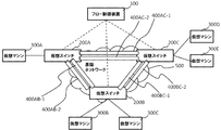
- FIG. 2 is a diagram illustrating a configuration of the overlay network system according to the first embodiment of this invention.
- a plurality of virtual switches 200A to 200C arranged as tunnel end points of the overlay network system, a flow control device 100 that controls these virtual switches 200, and these virtual switches 200 are used to communicate with each other.
- a configuration including virtual machines 300A to 300E is shown.
- VXLAN tunnels 400AB-1 to 400BC-2 which will be described later, are constructed.
- virtual switch 200 when the virtual switches 200A to 200C, the virtual machines 300A to 300E, and the VXLAN tunnels 400AB-1 to 400BC-2 are not particularly distinguished, they are referred to as “virtual switch 200”, “virtual machine 300”, and “VXLAN tunnel 400”, respectively. .
- the flow control device 100 performs flow management for constructing the VXLAN tunnel 400 in a mesh shape between the virtual switches 200, and instructs flow setting to one or more virtual switches 200. Thereby, the flow control apparatus 100 realizes a communication network between the virtual machines 300.
- Such a flow control device 100 can be realized by adding a tunnel management function to the OpenFlow controllers of Non-Patent Documents 2 and 3.
- the virtual switch 200 selects a flow entry having a matching condition that matches the input frame from the flow entries set by the instruction of the flow control apparatus 100 for the input frame from the virtual machine 300 or another virtual switch. To process the input frame.
- the virtual switch 200 outputs the input frame to the VXLAN tunnel 400 for connection with the other virtual machine 300 according to the selected flow entry, and outputs it to the other virtual switch 200 across the base network 500, or the flow control device 100. Output to or drop.
- the virtual machine 300 transmits a frame addressed to the other virtual machine 300 to the virtual switch 200 and receives a frame originating from the other virtual machine 300 from the virtual switch 200. Further, the virtual machine 300 does not need to be directly connected to the virtual switch 200 and may be connected via a layer 2 switch (L2SW), or the virtual machine 300 is a layer 3 switch (L3SW) or a router. In some cases, another virtual machine 300 is connected to the destination.
- L2SW layer 2 switch
- L3SW layer 3 switch
- another virtual machine 300 is connected to the destination.
- the virtual switch 200 and the virtual machine 300 in the connected state may be virtual entities that operate on the same virtualization server by using server virtualization technology.
- the infrastructure network 500 is a layer 3 network or the like for performing frame transfer between the virtual switches 200.
- the infrastructure network 500 can communicate with a destination IP address given when encapsulated in VXLAN, and when a multicast address is set as the destination, all virtual switches 200 It can be delivered to.
- FIG. 3 is a diagram illustrating a configuration of the virtual switch according to the first embodiment.
- the configuration includes a flow entry search unit 201, a flow entry storage unit 202, a flow entry processing unit 203, a flow processing unit 204, a flow control device communication unit 205, and a VXLAN processing unit 250. It is shown.
- the flow entry search unit 201, the flow entry storage unit 202, the flow entry processing unit 203, the flow processing unit 204, and the flow control device communication unit 205 correspond to the open flow switch function unit. Is done.
- the VXLAN processing unit 250 and the command processing unit 251 and the tunnel processing units 260-1 and 260-2 (hereinafter referred to as “tunnel processing unit 260” unless the tunnel processing units 260-1 and 260-2 are particularly distinguished). And.
- the tunnel processing unit 260 passes the VXLAN-encapsulated frame input from the VXLAN tunnel 400 to the flow entry search unit 201, and performs VXLAN decapsulation as necessary according to the instruction of the flow processing unit 204, and outputs it to the virtual machine 300.
- the tunnel processing unit 260 passes the frame input from the virtual machine 300 to the flow entry search unit 201, encapsulates VXLAN as necessary in accordance with the instruction of the flow processing unit 204, and establishes a virtual interface facing through the VXLAN tunnel 400. A process of transferring to the switch 200 is performed.
- the command processing unit 251 receives an operation from the user and outputs a UDP port number information change command or the like to the tunnel processing unit 260.
- the flow entry search unit 201 extracts flow entry search condition information for searching for a flow entry from the input frame, and searches the flow entry storage unit 203 using the flow entry search condition information. As a result of the search, the flow entry search unit 201 passes the action and input frame of the matched flow entry to the flow processing unit 204. In addition, the flow entry search unit 201 updates the time-out time and statistical information of the flow entry matched at that time, if any.
- the flow entry storage unit 202 uses a flow entry table set by the flow control device 100 and the like. The change of the flow entry in the flow entry storage unit 202 is reported to the flow control apparatus 100 and grasped. Therefore, the flow control apparatus 100 can grasp and control the behavior of the virtual switch 200.
- the flow entry processing unit 203 updates the flow entry storage unit 202 in accordance with an operation instruction or a reference instruction such as addition / deletion regarding a flow entry coming from the flow control apparatus 100 via the flow control apparatus communication unit 205. Further, the flow entry processing unit 203 refers to the flow entry storage unit 202, deletes the flow entry that has timed out, and sends the flow entry to the flow control device 100 via the flow control device communication unit 205. Report that it has been deleted.
- the flow processing unit 204 changes the value of the frame according to the input frame and its action passed from the flow control device 100 via the flow entry search unit 201 or via the flow control device communication unit 205, A frame is output or a frame is output to another virtual switch 200. Further, as necessary, the flow processing unit 204 instructs the VXLAN processing unit 250 to perform VXLAN encapsulation, outputs it to the VXLAN tunnel 400, performs VXLAN decapsulation of a frame input from the VXLAN tunnel 400, A frame is output to the flow control device 100 via the control device communication unit 205 or dropped.
- FIG. 4 is a diagram illustrating a configuration of a frame that is VXLAN encapsulated by the virtual switch according to the first embodiment of this invention.
- the tunnel processing unit 260 of the VXLAN processing unit 250 encapsulates the original frame with additional headers such as Outer MAC, Outer IP, Outer UDP, and VXLAN ID.
- additional headers such as Outer MAC, Outer IP, Outer UDP, and VXLAN ID.
- UDP port information numbers 601 and 602 described later are set in the Outer UDP header, which can be used for flow identification and load distribution (load balancing) using the same.
- decapsulation processing for removing the additional header from the encapsulated frame is performed.
- FIG. 5 is a diagram illustrating a configuration of the tunnel processing unit 260 in the virtual switch 200 according to the first embodiment. Referring to FIG. 5, a configuration including a VNI information storage unit 264, a tunnel release unit (decapsulation unit) 265, a UDP port information storage unit 266, and a tunneling unit (encapsulation unit) 267 is shown. Yes.
- the VNI information storage unit 264 holds a virtual network identifier (VNI) of VXLAN that the tunnel processing unit 260 has. This virtual network identifier (VNI) is stored in the VXLAN header of FIG.
- the tunnel release unit (decapsulation unit) 265 performs decapsulation by removing an additional header from the VXLAN frame of the frame input from the VXLAN tunnel 400.
- the UDP port information storage unit 266 holds UDP port information for the tunnel processing unit 260 to perform transmission / reception via the VXLAN tunnel 400.
- the UDP port number held in the UDP port information storage unit 266 is changed by a change command issued from the command processing unit 251.
- the UDP port information storage unit 266 can be shared by a plurality of tunnel processing units 260. That is, one UDP port number can be used for a plurality of VNIs.
- the tunneling unit (encapsulating unit) 267 When outputting to the VXLAN tunnel 400, the tunneling unit (encapsulating unit) 267 performs VXLAN encapsulation processing by adding an additional header to the original frame as shown in FIG.
- the command processing unit 251 receives an operation from the user, outputs a UDP port number information change command (UDP port number change notification) or the like to the tunnel processing unit 260, and rewrites the contents or the like of the UDP port information storage unit 266. Perform the action.
- UDP port number information change command UDP port number change notification
- the command processing unit 251 is provided to change the UDP port information storage unit 266.
- the configuration is changed by transmitting / receiving a special frame / packet for changing the UDP port number. It is also possible to perform this.
- 3 and 5 is realized by a computer program that causes a computer mounted on the virtual switch 200 to execute the above-described processes using the hardware thereof. You can also.
- FIG. 6 is a sequence diagram showing the operation of the first exemplary embodiment of the present invention.
- # 1 is set in the UDP port information storage unit 266 as a UDP port number used for VXLAN communication. Specifically, as shown in FIG. 7, at this time, only the UDP port number # 1 can receive a frame, and the UDP port number # 1 is set as the destination UDP port number at the time of frame transmission.
- the command processing unit 251 transmits a UDP port number change command (first instruction) for instructing the tunnel processing unit 260 to change the UDP port number from # 1 to # 2. (S001 in FIG. 6).
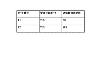
- the content of the UDP port information storage unit 266 of the tunnel processing unit 260 that has received the UDP port number change command (first instruction) is rewritten as shown in FIG. 8 (S002 in FIG. 6).
- an entry specifying UDP port number # 2 as a receivable port is added to the entry of FIG.
- the UDP port number # 2 is not the UDP port information used for the transmission destination (the transmission destination use field is NO).
- the user inputs a command for switching the transmission destination port to the new UDP port number # 2 to the virtual switch 200.
- the command processing unit 251 instructs the tunnel processing unit 260 to change the UDP port number used as the destination at the time of transmission from # 1 to # 2 (second port number switching command (second (Instruction) is transmitted (S003 in FIG. 6).
- the transmission destination use field in the UDP port information storage unit 266 of the tunnel processing unit 260 is rewritten as shown in FIG. 9 (S004 in FIG. 6).
- the transmission destination use field of the first entry in FIG. 8 is rewritten from YES to NO
- the transmission destination use field of the second entry of FIG. 8 is rewritten from NO to YES.
- This process corresponds to a process of switching from the UDP port number # 1 used for transmission destination to # 2.
- both UDP port numbers # 1 and # 2 are set as receivable UDP ports (both receivable port fields are YES).
- the user inputs a command for instructing the virtual switch 200 to open the pre-change UDP port number # 1.
- the command processing unit 251 transmits a pre-change UDP port number release command (third instruction) to the tunnel processing unit 260 (S005 in FIG. 6).
- the content of the UDP port information storage unit 266 of the tunnel processing unit 260 that has received the pre-change UDP port number release command (third instruction) is rewritten as shown in FIG. 10 (S006 in FIG. 6).
- the UDP port number # 1 is removed from the receivable UDP port of the first entry of FIG. 9 (changed from YES to NO).
- the UDP port number # 1 is released.
- the first entry is left in a state where NO is set in each field, but this entry is reused when changing from UDP port # 2 to # 1 again.
- the first entry itself may be deleted.
- the user can change the UDP port number (first instruction), the UDP port number switching command (second instruction), the pre-change UDP port number release command (third instruction).
- the switching of the UDP port number and the release of the pre-change UDP port number can be performed automatically after a lapse of a predetermined period. Further, when it is not necessary to release the pre-change UDP port number, the pre-change UDP port number release may be omitted.
- the flow control apparatus 100 on behalf of the user performs a UDP port number change command (first instruction), a UDP port number switching command (second instruction), a pre-change UDP port number release command (third instruction). Instruction) issuance instruction may be sent to the command processing unit 251. In this case, the flow control apparatus 100 can change the UDP port number with reference to a communication policy applied to the virtual machine.
- the virtual switch 200 has been described by assuming that it is connected by VXLAN, but the switch to which the present invention is applied is not limited to the virtual switch.
- some or all of the switches may be physical switches.
- the tunnel processing unit 260 passes the VXLAN-encapsulated frame input from the VXLAN tunnel 400 to the flow entry search unit 201, and in accordance with the instructions of the flow processing unit 204, In the above description, the VXLAN decapsulation is performed. However, the tunnel processing unit 260 may perform the VXLAN decapsulation and then pass the frame to the flow entry search unit 201. Similarly, when transmitting a frame received from a virtual machine, the input frame may be VXLAN encapsulated and then passed to the flow entry search unit 201.
- the flow identification information is a switch that is a UDP (User Datagram Protocol) port number.
- UDP User Datagram Protocol
- a switch comprising an OpenFlow switch function unit for processing a received frame after decapsulation and a transmission frame before encapsulation.
- a switch that receives an instruction to change the flow identification information from a control device that receives instructions regarding processing of the received frame after decapsulation and a transmission frame before encapsulation.
- Flow control apparatus 200 200A-200C Virtual switch 200a Switch 201 Flow entry search part 202 Flow entry memory
Abstract
The purpose of the present invention is to improve a function of changing tunnel setting information for a switch that functions as a tunnel endpoint of an overlay network system. In the present invention, a switch that functions as a tunnel endpoint of an overlay network system is equipped with: a tunnel processing unit that performs capsulization and decapsulization of frames sent to and received from the opposing tunnel endpoint; and a command processing unit that, upon receiving an instruction to change flow identification information for identifying a capsulized frame, instructs the tunnel processing unit to receive the frame with flow identification information for before and after the change, and thereafter instructs the tunnel processing unit to change the flow identification information to be set in a frame being sent.
Description
[関連出願についての記載]
本発明は、日本国特許出願:特願2014-156562号(2014年 7月31日出願)に基づくものであり、同出願の全記載内容は引用をもって本書に組み込み記載されているものとする。
本発明は、スイッチ、オーバーレイネットワークシステム、通信方法及びプログラムに関し、特に、対向するトンネルエンドポイントと送受信するフレームのカプセル化とデカプセル化とを行うトンネルエンドポイントとして機能するスイッチ、オーバーレイネットワークシステム、通信方法及びプログラムに関する。 [Description of related applications]
The present invention is based on a Japanese patent application: Japanese Patent Application No. 2014-156562 (filed on July 31, 2014), and the entire contents of this application are incorporated and incorporated herein by reference.
The present invention relates to a switch, an overlay network system, a communication method, and a program, and more particularly, a switch, an overlay network system, and a communication method that function as a tunnel endpoint that encapsulates and decapsulates a frame to be transmitted to and received from an opposite tunnel endpoint. And the program.
レイヤ3ネットワーク上に、仮想的なレイヤ2ネットワークを構築するタイプのオーバーレイネットワークシステムが知られている。このうちのVXLAN(Virtual eXtensible Local Area Network)は、UDPポート情報を追加ヘッダに埋め込み、これを用いて経路制御とロードバランシング機能を備えている。非特許文献1は、VXLANのドラフトである(Page 10、Outer UDP Headerの項参照)。
A type of overlay network system that builds a virtual layer 2 network on a layer 3 network is known. Of these, VXLAN (Virtual eXtensible Local Area Network) embeds UDP port information in an additional header and uses this to provide path control and load balancing functions. Non-Patent Document 1 is a draft of VXLAN (refer to the section of Page 10, Outer UDP Header).
特許文献1に、上記VXLAN等の大規模ネットワーク論理分割技術を用いて多数の論理的なネットワークを構築した構成におけるマルチキャストツリーの管理技術が開示されている。
Patent Document 1 discloses a management technique for a multicast tree in a configuration in which a large number of logical networks are constructed using a large-scale network logical partitioning technique such as VXLAN.
非特許文献2、3は、本発明の関連技術であるオープンフローのホワイトペーパーとオープンフローのスペックである。
Non-Patent Documents 2 and 3 are OpenFlow white papers and OpenFlow specifications that are related technologies of the present invention.
以下の分析は、本発明によって与えられたものである。上記オーバーレイネットワークシステムにおいて、物理ネットワークがフローを識別するためのフロー識別情報(VXLANの場合、UDPポート番号)を動的に変更したいという要望がある。
The following analysis is given by the present invention. In the overlay network system, there is a demand for dynamically changing flow identification information (in the case of VXLAN, UDP port number) for identifying a flow by the physical network.
しかしながら、それを実現するためには、オーバーレイネットワークシステムのトンネルエンドポイントとして機能する複数のスイッチに対して、トンネル設定として、フロー識別情報の変更設定を行う必要がある。その際に、設定のタイミングがずれてしまうとその間はネットワークの通信断が発生してしまうという問題点がある。
However, in order to realize this, it is necessary to change and set the flow identification information as a tunnel setting for a plurality of switches that function as tunnel endpoints of the overlay network system. At this time, if the setting timing is deviated, there is a problem that the network communication is interrupted.
本発明は、オーバーレイネットワークシステムのトンネルエンドポイントとして機能するスイッチのトンネル設定の変更機能の向上に貢献できるスイッチ、オーバーレイネットワークシステム、通信方法及びプログラムを提供することを目的とする。
An object of the present invention is to provide a switch, an overlay network system, a communication method, and a program that can contribute to an improvement in a tunnel setting change function of a switch that functions as a tunnel end point of an overlay network system.
第1の視点によれば、オーバーレイネットワークのトンネルエンドポイントとして、対向するトンネルエンドポイントと送受信するフレームのカプセル化とデカプセル化とを行うトンネル処理部を備えるスイッチが提供される。このスイッチは、さらに、カプセル化されたフレームを識別するためのフロー識別情報の変更指示の受信を契機に、前記トンネル処理部に対し、変更前後のフロー識別情報を持つフレームの受信を指示した後に、送信フレームに設定するフロー識別情報の変更を指示するコマンド処理部と、を備える。
According to a first aspect, there is provided a switch including a tunnel processing unit that performs encapsulation and decapsulation of a frame transmitted / received to / from an opposite tunnel endpoint as a tunnel endpoint of an overlay network. The switch further instructs the tunnel processing unit to receive a frame having flow identification information before and after the change, upon reception of a flow identification information change instruction for identifying the encapsulated frame. A command processing unit for instructing to change the flow identification information set in the transmission frame.
第2の視点によれば、上記したスイッチを用いて構成されたオーバーレイネットワークシステムが提供される。
According to the second viewpoint, an overlay network system configured using the above-described switch is provided.
第3の視点によれば、オーバーレイネットワークのトンネルエンドポイントとして、対向するトンネルエンドポイントと送受信するフレームのカプセル化とデカプセル化とを行うトンネル処理部を備えたスイッチにおいて、カプセル化されたフレームを識別するためのフロー識別情報の変更指示の受信を契機に、前記トンネル処理部に対し、変更前後のフロー識別情報を持つフレームの受信を指示するステップと、前記指示の後に、所定の契機で、送信フレームに設定するフロー識別情報の変更を指示するステップと、を含む通信方法が提供される。本方法は、オーバーレイネットワークのトンネルエンドポイントとして機能するスイッチという特定の機械に結びつけられている。
According to the third aspect, an encapsulated frame is identified as a tunnel end point of an overlay network in a switch having a tunnel processing unit that encapsulates and decapsulates a frame transmitted / received to / from an opposite tunnel end point. In response to reception of a flow identification information change instruction for sending, a step for instructing the tunnel processing unit to receive a frame having flow identification information before and after the change, and transmission at a predetermined opportunity after the instruction Instructing to change the flow identification information set in the frame. The method is tied to a specific machine called a switch that functions as a tunnel endpoint for the overlay network.
第4の視点によれば、オーバーレイネットワークのトンネルエンドポイントとして、対向するトンネルエンドポイントと送受信するフレームのカプセル化とデカプセル化とを行うトンネル処理部を備えたスイッチに搭載されたコンピュータに、カプセル化されたフレームを識別するためのフロー識別情報の変更指示の受信を契機に、前記トンネル処理部に対し、変更前後のフロー識別情報を持つフレームの受信を指示する処理と、前記指示の後に、所定の契機で、送信フレームに設定するフロー識別情報の変更を指示する処理と、を実行させるプログラムが提供される。なお、このプログラムは、コンピュータが読み取り可能な(非トランジエントな)記憶媒体に記録することができる。即ち、本発明は、コンピュータプログラム製品として具現することも可能である。
According to the fourth aspect, as a tunnel end point of an overlay network, encapsulation is performed on a computer mounted on a switch equipped with a tunnel processing unit that performs encapsulation and decapsulation of a frame transmitted to and received from an opposite tunnel end point. Triggered by reception of an instruction to change the flow identification information for identifying the received frame, a process for instructing the tunnel processing unit to receive a frame having flow identification information before and after the change, and after the instruction, In response to this, there is provided a program for executing processing for instructing change of flow identification information set in a transmission frame. This program can be recorded on a computer-readable (non-transient) storage medium. That is, the present invention can be embodied as a computer program product.
本発明によれば、オーバーレイネットワークシステムのトンネルエンドポイントとして機能するスイッチのトンネル設定情報の変更機能の向上に貢献することが可能となる。
According to the present invention, it is possible to contribute to the improvement of the change function of the tunnel setting information of the switch that functions as the tunnel end point of the overlay network system.
はじめに本発明の一実施形態の概要について図面を参照して説明する。なお、この概要に付記した図面参照符号は、理解を助けるための一例として各要素に便宜上付記したものであり、本発明を図示の態様に限定することを意図するものではない。
First, an outline of an embodiment of the present invention will be described with reference to the drawings. Note that the reference numerals of the drawings attached to this summary are attached to the respective elements for convenience as an example for facilitating understanding, and are not intended to limit the present invention to the illustrated embodiment.
本発明は、その一実施形態において、図1に示すように、オーバーレイネットワークのトンネルエンドポイントとして、対向するトンネルエンドポイントと送受信するフレームのカプセル化とデカプセル化とを行うトンネル処理部260aと、コマンド処理部251aとを備えたスイッチ200aにて実現できる。
In one embodiment of the present invention, as shown in FIG. 1, a tunnel processing unit 260a that performs encapsulation and decapsulation of a frame to be transmitted to and received from an opposite tunnel endpoint as a tunnel endpoint of an overlay network, and a command This can be realized by the switch 200a including the processing unit 251a.
より具体的には、コマンド処理部251aは、カプセル化されたフレームを識別するためのフロー識別情報の変更指示(例:AAA→BBB)の受信を契機に、前記トンネル処理部260aに対し、変更前後のフロー識別情報を持つフレームの受信(フロー識別情報=AAA及びBBBのフレームの受信)を指示する。そして、その後、所定の契機で、前記トンネル処理部260aに対し、送信フレームに設定するフロー識別情報の変更指示が行われる。なお、所定の契機としては、フロー識別情報の変更指示の受信から一定の期間の経過を条件としてもよいし、ユーザからの明示的な指示(送信フレームに設定するフロー識別情報の変更指示)がなされることを条件としてもよい。
More specifically, the command processing unit 251a changes the tunnel processing unit 260a in response to the reception of a flow identification information change instruction (eg, AAA → BBB) for identifying the encapsulated frame. The reception of a frame having preceding and following flow identification information (flow identification information = reception of AAA and BBB frames) is instructed. Then, at a predetermined opportunity, the tunnel processing unit 260a is instructed to change the flow identification information set in the transmission frame. It should be noted that the predetermined trigger may be based on the passage of a certain period from the reception of the flow identification information change instruction, or an explicit instruction from the user (instruction for changing the flow identification information set in the transmission frame). It may be conditional on being done.
以上のように構成することにより、トンネル通信に使用するフロー識別情報の変更による通信断の発生を抑止することができる。その理由は、フロー識別情報の変更指示の受信を契機に、直ちに受信対象フレームのフロー識別情報を変更せず、まず、変更前後のフロー識別情報での受信を行わせ、その後で、送信時に使用するフロー識別情報を変更することで、設定タイミングのずれを吸収するように構成したことにある。
By configuring as described above, it is possible to suppress the occurrence of communication disconnection due to the change of the flow identification information used for tunnel communication. The reason for this is that when the flow identification information change instruction is received, the flow identification information of the frame to be received is not changed immediately, but the flow identification information before and after the change is received first, and then used for transmission. In other words, it is configured to absorb the deviation of the setting timing by changing the flow identification information.
[第1の実施形態]
続いて本発明の第1の実施形態について図面を参照して詳細に説明する。図2は、本発明の第1の実施形態のオーバーレイネットワークシステムの構成を示す図である。図2を参照すると、オーバーレイネットワークシステムのトンネルエンドポイントとして配置された複数の仮想スイッチ200A~200Cと、これら仮想スイッチ200を制御するフロー制御装置100と、これら仮想スイッチ200を利用して互いに通信する仮想マシン300A~300Eとを含む構成が示されている。仮想スイッチ200間は、後述するVXLANトンネル400AB-1~400BC-2が構築されている。以下、仮想スイッチ200A~200C、仮想マシン300A~300E、及びVXLANトンネル400AB-1~400BC-2を特に区別しない場合、それぞれ「仮想スイッチ200」、「仮想マシン300」、「VXLANトンネル400」と記す。 [First Embodiment]
Next, a first embodiment of the present invention will be described in detail with reference to the drawings. FIG. 2 is a diagram illustrating a configuration of the overlay network system according to the first embodiment of this invention. Referring to FIG. 2, a plurality ofvirtual switches 200A to 200C arranged as tunnel end points of the overlay network system, a flow control device 100 that controls these virtual switches 200, and these virtual switches 200 are used to communicate with each other. A configuration including virtual machines 300A to 300E is shown. Between the virtual switches 200, VXLAN tunnels 400AB-1 to 400BC-2, which will be described later, are constructed. Hereinafter, when the virtual switches 200A to 200C, the virtual machines 300A to 300E, and the VXLAN tunnels 400AB-1 to 400BC-2 are not particularly distinguished, they are referred to as “virtual switch 200”, “virtual machine 300”, and “VXLAN tunnel 400”, respectively. .
続いて本発明の第1の実施形態について図面を参照して詳細に説明する。図2は、本発明の第1の実施形態のオーバーレイネットワークシステムの構成を示す図である。図2を参照すると、オーバーレイネットワークシステムのトンネルエンドポイントとして配置された複数の仮想スイッチ200A~200Cと、これら仮想スイッチ200を制御するフロー制御装置100と、これら仮想スイッチ200を利用して互いに通信する仮想マシン300A~300Eとを含む構成が示されている。仮想スイッチ200間は、後述するVXLANトンネル400AB-1~400BC-2が構築されている。以下、仮想スイッチ200A~200C、仮想マシン300A~300E、及びVXLANトンネル400AB-1~400BC-2を特に区別しない場合、それぞれ「仮想スイッチ200」、「仮想マシン300」、「VXLANトンネル400」と記す。 [First Embodiment]
Next, a first embodiment of the present invention will be described in detail with reference to the drawings. FIG. 2 is a diagram illustrating a configuration of the overlay network system according to the first embodiment of this invention. Referring to FIG. 2, a plurality of
フロー制御装置100は、仮想スイッチ200間に、VXLANトンネル400をメッシュ状に構築するためのフロー管理をしており、1以上の仮想スイッチ200に対してフロー設定の指示を行う。これにより、フロー制御装置100は、仮想マシン300間の通信用ネットワークを実現する。なお、このようなフロー制御装置100は、非特許文献2、3のオープンフローコントローラにトンネル管理機能を追加することで実現できる。
The flow control device 100 performs flow management for constructing the VXLAN tunnel 400 in a mesh shape between the virtual switches 200, and instructs flow setting to one or more virtual switches 200. Thereby, the flow control apparatus 100 realizes a communication network between the virtual machines 300. Such a flow control device 100 can be realized by adding a tunnel management function to the OpenFlow controllers of Non-Patent Documents 2 and 3.
仮想スイッチ200は、仮想マシン300もしくは他の仮想スイッチからの入力フレームに対してフロー制御装置100の指示によって設定されたフローエントリの中から、入力フレームに適合するマッチ条件を持つフローエントリを選択して入力フレームの処理を行う。仮想スイッチ200は、選択したフローエントリによって入力フレームを他の仮想マシン300との接続用のVXLANトンネル400に出力し、基盤ネットワーク500を越えて他の仮想スイッチ200に出力したり、フロー制御装置100に出力したり、ドロップしたりする。
The virtual switch 200 selects a flow entry having a matching condition that matches the input frame from the flow entries set by the instruction of the flow control apparatus 100 for the input frame from the virtual machine 300 or another virtual switch. To process the input frame. The virtual switch 200 outputs the input frame to the VXLAN tunnel 400 for connection with the other virtual machine 300 according to the selected flow entry, and outputs it to the other virtual switch 200 across the base network 500, or the flow control device 100. Output to or drop.
仮想マシン300は、他の仮想マシン300宛てのフレームを仮想スイッチ200に送信したり、他の仮想マシン300を送信元とするフレームを仮想スイッチ200から受信したりする。また、仮想マシン300は、仮想スイッチ200と直接接続している必要はなくレイヤ2スイッチ(L2SW)を介して接続していてもよいし、仮想マシン300がレイヤ3スイッチ(L3SW)やルータであり、その先に別の仮想マシン300が接続されている場合もある。
The virtual machine 300 transmits a frame addressed to the other virtual machine 300 to the virtual switch 200 and receives a frame originating from the other virtual machine 300 from the virtual switch 200. Further, the virtual machine 300 does not need to be directly connected to the virtual switch 200 and may be connected via a layer 2 switch (L2SW), or the virtual machine 300 is a layer 3 switch (L3SW) or a router. In some cases, another virtual machine 300 is connected to the destination.
また、接続状態にある仮想スイッチ200と仮想マシン300は、サーバ仮想化技術を利用して、同一の仮想化サーバ上で動作する仮想エンティティであってもよい。
Further, the virtual switch 200 and the virtual machine 300 in the connected state may be virtual entities that operate on the same virtualization server by using server virtualization technology.
VXLANトンネル400は、仮想スイッチ200間で基盤ネットワーク500を介して通信を行うためのオーバーレイトンネルである。仮想ネットワーク識別子VNI(VXLAN Network Identifier)と通信を行う2台の仮想スイッチ200の組み合わせにつき1個存在する。図2の例では、3台の仮想スイッチ間にそれぞれ2つのVNIのVXLANトンネル400が構築されている。なお以下の説明において、仮想スイッチ200Aと仮想スイッチ200Bとの間のVNI=1のVXLANトンネル400を、VXLANトンネル400AB-1という形で表す。
The VXLAN tunnel 400 is an overlay tunnel for performing communication between the virtual switches 200 via the infrastructure network 500. There is one for each combination of two virtual switches 200 that communicate with a virtual network identifier VNI (VXLAN Network Identifier). In the example of FIG. 2, two VNI VXLAN tunnels 400 are respectively constructed between three virtual switches. In the following description, the VXLAN tunnel 400 with VNI = 1 between the virtual switch 200A and the virtual switch 200B is represented in the form of VXLAN tunnel 400AB-1.
基盤ネットワーク500は、仮想スイッチ200間のフレーム転送を行うためのレイヤ3ネットワーク等である。本実施形態では、基盤ネットワーク500は、VXLANにてカプセル化された際に付与される宛先IPアドレスへの通信が可能であり、宛先にマルチキャストアドレスが設定されている場合には、全仮想スイッチ200への配信が可能であるものとする。
The infrastructure network 500 is a layer 3 network or the like for performing frame transfer between the virtual switches 200. In this embodiment, the infrastructure network 500 can communicate with a destination IP address given when encapsulated in VXLAN, and when a multicast address is set as the destination, all virtual switches 200 It can be delivered to.
図3は、第1の実施形態の仮想スイッチの構成を示す図である。図3を参照すると、フローエントリ検索部201と、フローエントリ記憶部202と、フローエントリ処理部203と、フロー処理部204と、フロー制御装置通信部205と、VXLAN処理部250とを備えた構成が示されている。このうち、フローエントリ検索部201、フローエントリ記憶部202、フローエントリ処理部203、フロー処理部204、及びフロー制御装置通信部205が、オープンフロースイッチ機能部に相当する。
される。 FIG. 3 is a diagram illustrating a configuration of the virtual switch according to the first embodiment. Referring to FIG. 3, the configuration includes a flowentry search unit 201, a flow entry storage unit 202, a flow entry processing unit 203, a flow processing unit 204, a flow control device communication unit 205, and a VXLAN processing unit 250. It is shown. Among these, the flow entry search unit 201, the flow entry storage unit 202, the flow entry processing unit 203, the flow processing unit 204, and the flow control device communication unit 205 correspond to the open flow switch function unit.
Is done.
される。 FIG. 3 is a diagram illustrating a configuration of the virtual switch according to the first embodiment. Referring to FIG. 3, the configuration includes a flow
Is done.
VXLAN処理部250は、コマンド処理部251とトンネル処理部260-1、260-2(以降、トンネル処理部260-1、260-2を特に区別しない場合、「トンネル処理部260」と記す。)とを備えている。トンネル処理部260は、VXLANトンネル400から入力されたVXLANカプセル化されたフレームをフローエントリ検索部201に渡し、フロー処理部204の指示に従い、必要に応じVXLANデカプセル化して仮想マシン300に出力する。また、トンネル処理部260は、仮想マシン300から入力されたフレームをフローエントリ検索部201に渡して、フロー処理部204の指示に従い、必要に応じVXLANカプセル化し、VXLANトンネル400を介して対向する仮想スイッチ200へと転送する処理を行う。
The VXLAN processing unit 250 and the command processing unit 251 and the tunnel processing units 260-1 and 260-2 (hereinafter referred to as “tunnel processing unit 260” unless the tunnel processing units 260-1 and 260-2 are particularly distinguished). And. The tunnel processing unit 260 passes the VXLAN-encapsulated frame input from the VXLAN tunnel 400 to the flow entry search unit 201, and performs VXLAN decapsulation as necessary according to the instruction of the flow processing unit 204, and outputs it to the virtual machine 300. In addition, the tunnel processing unit 260 passes the frame input from the virtual machine 300 to the flow entry search unit 201, encapsulates VXLAN as necessary in accordance with the instruction of the flow processing unit 204, and establishes a virtual interface facing through the VXLAN tunnel 400. A process of transferring to the switch 200 is performed.
コマンド処理部251はユーザからの操作を受け付け、トンネル処理部260に対して、UDPポート番号情報の変更コマンド等を出力する。
The command processing unit 251 receives an operation from the user and outputs a UDP port number information change command or the like to the tunnel processing unit 260.
フローエントリ検索部201は、入力されたフレームからフローエントリを検索するためのフローエントリ検索条件情報を抽出し、フローエントリ検索条件情報を用いてフローエントリ記憶部203を検索する。フローエントリ検索部201は、前記検索の結果、マッチしたフローエントリのアクションと入力フレームをフロー処理部204に渡す。また、フローエントリ検索部201は、その際にマッチしたフローエントリのタイムアウト時間や統計情報などがあればこれらを更新する。
The flow entry search unit 201 extracts flow entry search condition information for searching for a flow entry from the input frame, and searches the flow entry storage unit 203 using the flow entry search condition information. As a result of the search, the flow entry search unit 201 passes the action and input frame of the matched flow entry to the flow processing unit 204. In addition, the flow entry search unit 201 updates the time-out time and statistical information of the flow entry matched at that time, if any.
フローエントリ記憶部202は、フロー制御装置100より設定されたフローエントリテーブル等を用いて保持する。なお、フローエントリ記憶部202におけるフローエントリの異動は、フロー制御装置100に報告され、把握されている。従って、フロー制御装置100は、仮想スイッチ200のふるまいを把握し、制御可能となっている。
The flow entry storage unit 202 uses a flow entry table set by the flow control device 100 and the like. The change of the flow entry in the flow entry storage unit 202 is reported to the flow control apparatus 100 and grasped. Therefore, the flow control apparatus 100 can grasp and control the behavior of the virtual switch 200.
フローエントリ処理部203は、フロー制御装置通信部205を介してフロー制御装置100から来るフローエントリに関する追加・削除などの操作指示や参照指示に従い、フローエントリ記憶部202の更新等を行う。また、フローエントリ処理部203は、フローエントリ記憶部202を参照し、フローエントリでタイムアウトしたものに関しては削除し、フロー制御装置通信部205を介してフロー制御装置100に対して、該フローエントリが削除されたことを報告する。
The flow entry processing unit 203 updates the flow entry storage unit 202 in accordance with an operation instruction or a reference instruction such as addition / deletion regarding a flow entry coming from the flow control apparatus 100 via the flow control apparatus communication unit 205. Further, the flow entry processing unit 203 refers to the flow entry storage unit 202, deletes the flow entry that has timed out, and sends the flow entry to the flow control device 100 via the flow control device communication unit 205. Report that it has been deleted.
フロー処理部204は、フローエントリ検索部201から、又は、フロー制御装置通信部205を介して、フロー制御装置100から渡される入力フレームとそのアクションに従ってフレームの値を変更したり、仮想マシン300にフレームを出力したり、他の仮想スイッチ200にフレームを出力する。また、必要に応じて、フロー処理部204は、VXLAN処理部250にVXLANカプセル化を指示し、VXLANトンネル400に出力したり、VXLANトンネル400から入力されたフレームのVXLANデカプセル化をしたり、フロー制御装置通信部205を介してフロー制御装置100にフレームを出力したり、ドロップしたりする。
The flow processing unit 204 changes the value of the frame according to the input frame and its action passed from the flow control device 100 via the flow entry search unit 201 or via the flow control device communication unit 205, A frame is output or a frame is output to another virtual switch 200. Further, as necessary, the flow processing unit 204 instructs the VXLAN processing unit 250 to perform VXLAN encapsulation, outputs it to the VXLAN tunnel 400, performs VXLAN decapsulation of a frame input from the VXLAN tunnel 400, A frame is output to the flow control device 100 via the control device communication unit 205 or dropped.
図4は、本発明の第1の実施形態の仮想スイッチによりVXLANカプセル化されたフレームの構成を示す図である。VXLAN処理部250のトンネル処理部260は、VXLANカプセル化する場合、オリジナルフレームに、Outer MAC、Outer IP、Outer UDP、VXLAN IDといった追加ヘッダにてカプセル化を行う。このうちのOuter UDPヘッダに後記するUDPポート情報番号601、602が設定され、フロー識別やこれを利用した負荷分散(ロードバランシング)に利用可能となっている。デカプセル化の場合には、上記カプセル化されたフレームから追加ヘッダを取り外す処理が行われる。
FIG. 4 is a diagram illustrating a configuration of a frame that is VXLAN encapsulated by the virtual switch according to the first embodiment of this invention. When performing VXLAN encapsulation, the tunnel processing unit 260 of the VXLAN processing unit 250 encapsulates the original frame with additional headers such as Outer MAC, Outer IP, Outer UDP, and VXLAN ID. Of these, UDP port information numbers 601 and 602 described later are set in the Outer UDP header, which can be used for flow identification and load distribution (load balancing) using the same. In the case of decapsulation, processing for removing the additional header from the encapsulated frame is performed.
図5は、第1の実施形態の仮想スイッチ200内のトンネル処理部260の構成を示す図である。図5を参照すると、VNI情報記憶部264と、トンネル解除部(デカプセル化部)265と、UDPポート情報記憶部266と、トンネル化部(カプセル化部)267とを備えた構成が示されている。
FIG. 5 is a diagram illustrating a configuration of the tunnel processing unit 260 in the virtual switch 200 according to the first embodiment. Referring to FIG. 5, a configuration including a VNI information storage unit 264, a tunnel release unit (decapsulation unit) 265, a UDP port information storage unit 266, and a tunneling unit (encapsulation unit) 267 is shown. Yes.
VNI情報記憶部264はトンネル処理部260が持つVXLANの仮想ネットワーク識別子(VNI)を保持する。この仮想ネットワーク識別子(VNI)は、図4のVXLANヘッダに格納される。
The VNI information storage unit 264 holds a virtual network identifier (VNI) of VXLAN that the tunnel processing unit 260 has. This virtual network identifier (VNI) is stored in the VXLAN header of FIG.
トンネル解除部(デカプセル化部)265は、VXLANトンネル400から入力されたフレームのVXLANフレームから追加ヘッダの除去等を行い、デカプセル化する。
The tunnel release unit (decapsulation unit) 265 performs decapsulation by removing an additional header from the VXLAN frame of the frame input from the VXLAN tunnel 400.
UDPポート情報記憶部266は、トンネル処理部260がVXLANトンネル400を介して送受信を行うためのUDPポート情報を保持する。UDPポート情報記憶部266に保持されるUDPポート番号は、コマンド処理部251から発行される変更コマンドにより変更される。なお、UDPポート情報記憶部266は、複数のトンネル処理部260で共有することが可能である。すなわち、複数のVNIに対して1個のUDPポート番号を使用することが可能である。
The UDP port information storage unit 266 holds UDP port information for the tunnel processing unit 260 to perform transmission / reception via the VXLAN tunnel 400. The UDP port number held in the UDP port information storage unit 266 is changed by a change command issued from the command processing unit 251. The UDP port information storage unit 266 can be shared by a plurality of tunnel processing units 260. That is, one UDP port number can be used for a plurality of VNIs.
トンネル化部(カプセル化部)267はVXLANトンネル400へ出力する際に、図4に示すようにオリジナルフレームに追加ヘッダを付加してVXLANカプセル化処理を行う。
When outputting to the VXLAN tunnel 400, the tunneling unit (encapsulating unit) 267 performs VXLAN encapsulation processing by adding an additional header to the original frame as shown in FIG.
コマンド処理部251はユーザからの操作を受け付け、トンネル処理部260に対して、UDPポート番号情報の変更コマンド(UDPポート番号変更通知)等を出力し、UDPポート情報記憶部266の内容等を書き換える動作を行う。
The command processing unit 251 receives an operation from the user, outputs a UDP port number information change command (UDP port number change notification) or the like to the tunnel processing unit 260, and rewrites the contents or the like of the UDP port information storage unit 266. Perform the action.
なお、本実施形態では、コマンド処理部251を設けて、UDPポート情報記憶部266を変更する構成を採用しているが、UDPポート番号変更のための特殊なフレーム/パケットを送受信することにより変更を行う方法も考えられる。
In this embodiment, the command processing unit 251 is provided to change the UDP port information storage unit 266. However, the configuration is changed by transmitting / receiving a special frame / packet for changing the UDP port number. It is also possible to perform this.
なお、図3、図5に示した仮想スイッチ200の各部(処理手段)は、仮想スイッチ200に搭載されるコンピュータに、そのハードウェアを用いて、上記した各処理を実行させるコンピュータプログラムにより実現することもできる。
3 and 5 is realized by a computer program that causes a computer mounted on the virtual switch 200 to execute the above-described processes using the hardware thereof. You can also.
続いて、本実施形態の動作について図面を参照して詳細に説明する。図6は、本発明の第1の実施形態の動作を表したシーケンス図である。
Subsequently, the operation of the present embodiment will be described in detail with reference to the drawings. FIG. 6 is a sequence diagram showing the operation of the first exemplary embodiment of the present invention.
初期状態として、図7に示すように、UDPポート情報記憶部266に、VXLAN通信に用いるUDPポート番号として、#1が設定されているものとする。具体的には、図7で示すように、この時点では、UDPポート番号#1のみがフレーム受信可能、かつ、フレーム送信時の宛先UDPポート番号としてUDPポート番号#1が設定されている。
As an initial state, as shown in FIG. 7, it is assumed that # 1 is set in the UDP port information storage unit 266 as a UDP port number used for VXLAN communication. Specifically, as shown in FIG. 7, at this time, only the UDP port number # 1 can receive a frame, and the UDP port number # 1 is set as the destination UDP port number at the time of frame transmission.
この状態で、図6に示すように、ユーザは、すべての仮想スイッチ200A~200Cの設定を切り替えるため、各仮想スイッチ200に対してUDPポート番号の変更を指示したものとする。前記指示を受けたコマンド処理部251は、トンネル処理部260に対して、UDPポート番号を#1から#2へ変更することを指示するUDPポート番号変更コマンド(第1の指示)を送信する(図6のS001)。
In this state, as shown in FIG. 6, it is assumed that the user instructs each virtual switch 200 to change the UDP port number in order to switch the settings of all the virtual switches 200A to 200C. Upon receiving the instruction, the command processing unit 251 transmits a UDP port number change command (first instruction) for instructing the tunnel processing unit 260 to change the UDP port number from # 1 to # 2. (S001 in FIG. 6).
前記UDPポート番号の変更コマンド(第1の指示)を受信したトンネル処理部260のUDPポート情報記憶部266の内容は、図8に示すとおり書き換えられる(図6のS002)。図8の例では、図7のエントリに、受信可能ポートとしてUDPポート番号#2を指定したエントリが追加されている。なお、この時点では、UDPポート番号#2は、送信時宛先に使用するUDPポート情報とはなっていない(送信時宛先使用フィールドがNO)。
The content of the UDP port information storage unit 266 of the tunnel processing unit 260 that has received the UDP port number change command (first instruction) is rewritten as shown in FIG. 8 (S002 in FIG. 6). In the example of FIG. 8, an entry specifying UDP port number # 2 as a receivable port is added to the entry of FIG. At this time, the UDP port number # 2 is not the UDP port information used for the transmission destination (the transmission destination use field is NO).
次に、ユーザは、仮想スイッチ200に対して送信時宛先ポートを新UDPポート番号#2に切替えるコマンドを入力する。前記指示を受けたコマンド処理部251は、トンネル処理部260に対して、送信時宛先に使用するUDPポート番号を#1から#2へ変更することを指示するUDPポート番号切替コマンド(第2の指示)を送信する(図6のS003)。
Next, the user inputs a command for switching the transmission destination port to the new UDP port number # 2 to the virtual switch 200. Upon receiving the instruction, the command processing unit 251 instructs the tunnel processing unit 260 to change the UDP port number used as the destination at the time of transmission from # 1 to # 2 (second port number switching command (second (Instruction) is transmitted (S003 in FIG. 6).
前記UDPポート番号の切替コマンド(第2の指示)を受信したトンネル処理部260のUDPポート情報記憶部266の送信時宛先使用フィールドが、図9に示すとおり書き換えられる(図6のS004)。図9の例では、図8の1番目のエントリの送信時宛先使用フィールドがYESからNOに書き換えられ、図8の2番目のエントリの送信時宛先使用フィールドがNOからYESに書き換えられている。この処理は、送信時宛先使用のUDPポート番号#1から#2に切り替える処理に相当する。なお、この時点においては、受信可能UDPポートとして、UDPポート番号#1、#2の双方が設定された状態が維持されている(受信可能ポートフィールドが共にYES)。
When the UDP port number switching command (second instruction) is received, the transmission destination use field in the UDP port information storage unit 266 of the tunnel processing unit 260 is rewritten as shown in FIG. 9 (S004 in FIG. 6). In the example of FIG. 9, the transmission destination use field of the first entry in FIG. 8 is rewritten from YES to NO, and the transmission destination use field of the second entry of FIG. 8 is rewritten from NO to YES. This process corresponds to a process of switching from the UDP port number # 1 used for transmission destination to # 2. At this time, both UDP port numbers # 1 and # 2 are set as receivable UDP ports (both receivable port fields are YES).
次に、ユーザは、仮想スイッチ200に対して変更前UDPポート番号#1の開放を指示するコマンドを入力する。前記指示を受けたコマンド処理部251は、トンネル処理部260に対して、変更前UDPポート番号解放コマンド(第3の指示)を送信する(図6のS005)。
Next, the user inputs a command for instructing the virtual switch 200 to open the pre-change UDP port number # 1. Upon receiving the instruction, the command processing unit 251 transmits a pre-change UDP port number release command (third instruction) to the tunnel processing unit 260 (S005 in FIG. 6).
前記変更前UDPポート番号解放コマンド(第3の指示)を受信したトンネル処理部260のUDPポート情報記憶部266の内容は、図10に示すとおり書き換えられる(図6のS006)。図10の例では、図9の1番目のエントリの受信可能UDPポートから、UDPポート番号#1が外されている(YES→NOに変更。)。これにより、UDPポート番号#1が解放されたことになる。なお、図10の例では、各フィールドにNOを設定した状態で1番目のエントリを残しているが、このエントリは、再度、UDPポート#2から#1への変更時に再使用される。もちろん、その必要性が無い場合は、1番目のエントリ自体を削除してしまってもよい。
The content of the UDP port information storage unit 266 of the tunnel processing unit 260 that has received the pre-change UDP port number release command (third instruction) is rewritten as shown in FIG. 10 (S006 in FIG. 6). In the example of FIG. 10, the UDP port number # 1 is removed from the receivable UDP port of the first entry of FIG. 9 (changed from YES to NO). As a result, the UDP port number # 1 is released. In the example of FIG. 10, the first entry is left in a state where NO is set in each field, but this entry is reused when changing from UDP port # 2 to # 1 again. Of course, if there is no necessity, the first entry itself may be deleted.
以上説明したように、本実施形態によれば、システムを構成する各仮想スイッチに対してUDPポート番号の変更設定タイミングがずれてしまった場合でも、ネットワークの通信断の発生を抑止することができる。
As described above, according to the present embodiment, even when the change setting timing of the UDP port number shifts with respect to each virtual switch constituting the system, it is possible to suppress the occurrence of network communication disconnection. .
以上、本発明の各実施形態を説明したが、本発明は、上記した実施形態に限定されるものではなく、本発明の基本的技術的思想を逸脱しない範囲で、更なる変形・置換・調整を加えることができる。例えば、各図面に示したネットワーク構成、各要素の構成、メッセージの表現形態は、本発明の理解を助けるための一例であり、これらの図面に示した構成に限定されるものではない。
Although the embodiments of the present invention have been described above, the present invention is not limited to the above-described embodiments, and further modifications, substitutions, and adjustments are possible without departing from the basic technical idea of the present invention. Can be added. For example, the network configuration, the configuration of each element, and the expression form of a message shown in each drawing are examples for helping understanding of the present invention, and are not limited to the configuration shown in these drawings.
例えば、上記した第1の実施形態では、ユーザからUDPポート番号の変更コマンド(第1の指示)、前記UDPポート番号の切替コマンド(第2の指示)、変更前UDPポート番号解放コマンド(第3の指示)の発行指示がなされるものとして説明したが、前記UDPポート番号の切替と、変更前UDPポート番号解放は、所定期間の経過後に実行される自動処理とすることができる。また、変更前UDPポート番号解放が必要ない場合は、変更前UDPポート番号解放を省略することもできる。
For example, in the first embodiment described above, the user can change the UDP port number (first instruction), the UDP port number switching command (second instruction), the pre-change UDP port number release command (third instruction). However, the switching of the UDP port number and the release of the pre-change UDP port number can be performed automatically after a lapse of a predetermined period. Further, when it is not necessary to release the pre-change UDP port number, the pre-change UDP port number release may be omitted.
また、ユーザに代わってフロー制御装置100が、UDPポート番号の変更コマンド(第1の指示)、前記UDPポート番号の切替コマンド(第2の指示)、変更前UDPポート番号解放コマンド(第3の指示)の発行指示をコマンド処理部251に送るようにしてもよい。この場合、フロー制御装置100が、仮想マシンに適用される通信ポリシー等を参照して、UDPポート番号の変更することが可能となる。
In addition, the flow control apparatus 100 on behalf of the user performs a UDP port number change command (first instruction), a UDP port number switching command (second instruction), a pre-change UDP port number release command (third instruction). Instruction) issuance instruction may be sent to the command processing unit 251. In this case, the flow control apparatus 100 can change the UDP port number with reference to a communication policy applied to the virtual machine.
また例えば、上記した第1の実施形態では、VXLANで接続されることを想定して、仮想スイッチ200を例示して説明したが、本発明が適用されるスイッチは、仮想スイッチに限定されない。例えば、一部のスイッチ又は全部が物理スイッチであってもよい。
For example, in the above-described first embodiment, the virtual switch 200 has been described by assuming that it is connected by VXLAN, but the switch to which the present invention is applied is not limited to the virtual switch. For example, some or all of the switches may be physical switches.
また例えば、上記した第1の実施形態では、トンネル処理部260は、VXLANトンネル400から入力されたVXLANカプセル化されたフレームをフローエントリ検索部201に渡し、フロー処理部204の指示に従い、必要に応じVXLANデカプセル化するものとして説明したが、トンネル処理部260が、VXLANデカプセル化してから、フレームをフローエントリ検索部201に渡す構成とすることもできる。同様に、仮想マシンから受信したフレームを送信する際も、入力されたフレームをVXLANカプセル化してから、フローエントリ検索部201に渡す構成とすることもできる。
Also, for example, in the first embodiment described above, the tunnel processing unit 260 passes the VXLAN-encapsulated frame input from the VXLAN tunnel 400 to the flow entry search unit 201, and in accordance with the instructions of the flow processing unit 204, In the above description, the VXLAN decapsulation is performed. However, the tunnel processing unit 260 may perform the VXLAN decapsulation and then pass the frame to the flow entry search unit 201. Similarly, when transmitting a frame received from a virtual machine, the input frame may be VXLAN encapsulated and then passed to the flow entry search unit 201.
最後に、本発明の好ましい形態を要約する。
[第1の形態]
(上記第1の視点によるスイッチ参照)
[第2の形態]
第1の形態のスイッチにおいて、
前記コマンド処理部は、
第1の指示の受信を契機に、変更前後のフロー識別情報でのフレーム受信を開始するよう前記トンネル処理部に指示し、
第2の指示の受信を契機に、送信フレームへの変更後のフロー識別の格納を開始するよう前記トンネル処理部に指示するスイッチ。
[第3の形態]
第1又は第2の形態のスイッチにおいて、
前記コマンド処理部は、
第3の指示の受信を契機に、変更前のフロー識別情報でのフレーム受信を終了するよう前記トンネル処理部に指示するスイッチ。
[第4の形態]
第1から第3いずれか一の形態のスイッチにおいて、
前記フロー識別情報は、UDP(User Datagram Protocol)ポート番号であるスイッチ。
[第5の形態]
第1から第4いずれか一の形態のスイッチにおいて、
さらに、デカプセル化後の受信フレーム及びカプセル化前の送信フレームの処理を行うオープンフロースイッチ機能部を備えるスイッチ。
[第6の形態]
第5の形態のスイッチにおいて、
前記デカプセル化後の受信フレーム及びカプセル化前の送信フレームの処理に関する指示を受け取る制御装置から、前記フロー識別情報の変更指示を受信するスイッチ。
[第7の形態]
(上記第2の視点によるオーバーレイネットワークシステム参照)
[第8の形態]
(上記第3の視点による通信方法参照)
[第9の形態]
(上記第4の視点によるプログラム参照)
なお、上記第7~第9の形態は、第1の形態と同様に、第2~第6の形態に展開することが可能である。 Finally, a preferred form of the invention is summarized.
[First embodiment]
(Refer to the switch from the first viewpoint above.)
[Second form]
In the switch of the first form,
The command processing unit
In response to the reception of the first instruction, the tunnel processing unit is instructed to start frame reception with the flow identification information before and after the change,
A switch for instructing the tunnel processing unit to start storing the flow identification after the change to the transmission frame upon reception of the second instruction.
[Third embodiment]
In the switch of the first or second form,
The command processing unit
A switch that instructs the tunnel processing unit to end frame reception with the flow identification information before the change upon reception of the third instruction.
[Fourth form]
In the switch of any one of the first to third forms,
The flow identification information is a switch that is a UDP (User Datagram Protocol) port number.
[Fifth embodiment]
In the switch according to any one of the first to fourth aspects,
Furthermore, a switch comprising an OpenFlow switch function unit for processing a received frame after decapsulation and a transmission frame before encapsulation.
[Sixth embodiment]
In the switch of the fifth form,
A switch that receives an instruction to change the flow identification information from a control device that receives instructions regarding processing of the received frame after decapsulation and a transmission frame before encapsulation.
[Seventh form]
(Refer to the overlay network system from the second viewpoint)
[Eighth form]
(Refer to the communication method according to the third viewpoint)
[Ninth Embodiment]
(Refer to the program from the fourth viewpoint above.)
Note that the seventh to ninth embodiments can be developed into the second to sixth embodiments as in the first embodiment.
なお、上記の特許文献および非特許文献の各開示を、本書に引用をもって繰り込むものとする。本発明の全開示(請求の範囲を含む)の枠内において、さらにその基本的技術思想に基づいて、実施形態ないし実施例の変更・調整が可能である。また、本発明の開示の枠内において種々の開示要素(各請求項の各要素、各実施形態ないし実施例の各要素、各図面の各要素等を含む)の多様な組み合わせ、ないし選択が可能である。すなわち、本発明は、請求の範囲を含む全開示、技術的思想にしたがって当業者であればなし得るであろう各種変形、修正を含むことは勿論である。特に、本書に記載した数値範囲については、当該範囲内に含まれる任意の数値ないし小範囲が、別段の記載のない場合でも具体的に記載されているものと解釈されるべきである。
It should be noted that the disclosures of the above patent documents and non-patent documents are incorporated herein by reference. Within the scope of the entire disclosure (including claims) of the present invention, the embodiments and examples can be changed and adjusted based on the basic technical concept. Various combinations or selections of various disclosed elements (including each element of each claim, each element of each embodiment or example, each element of each drawing, etc.) are possible within the scope of the disclosure of the present invention. It is. That is, the present invention of course includes various variations and modifications that could be made by those skilled in the art according to the entire disclosure including the claims and the technical idea. In particular, with respect to the numerical ranges described in this document, any numerical value or small range included in the range should be construed as being specifically described even if there is no specific description.
100 フロー制御装置
200、200A~200C 仮想スイッチ
200a スイッチ
201 フローエントリ検索部
202 フローエントリ記憶部
203 フローエントリ処理部
204 フロー処理部
205 フロー制御装置通信部
250 VXLAN処理部
251、251a コマンド処理部
260、260a、260-1、260-2 トンネル処理部
264 VNI情報記憶部
265 トンネル解除部(デカプセル化部)
266 UDPポート情報記憶部
267 トンネル化部(カプセル化部)
300、300A~300E 仮想マシン
400、400AB-1~400BC-2 VXLANトンネル
500 基盤ネットワーク
601、602 UDPポート番号情報 DESCRIPTION OFSYMBOLS 100 Flow control apparatus 200, 200A-200C Virtual switch 200a Switch 201 Flow entry search part 202 Flow entry memory | storage part 203 Flow entry process part 204 Flow process part 205 Flow control apparatus communication part 250 VXLAN process part 251,251a Command process part 260, 260a, 260-1, 260-2 Tunnel processing unit 264 VNI information storage unit 265 Tunnel release unit (decapsulation unit)
266 UDP portinformation storage unit 267 Tunneling unit (encapsulation unit)
300, 300A to 300EVirtual machine 400, 400AB-1 to 400BC-2 VXLAN tunnel 500 Base network 601, 602 UDP port number information
200、200A~200C 仮想スイッチ
200a スイッチ
201 フローエントリ検索部
202 フローエントリ記憶部
203 フローエントリ処理部
204 フロー処理部
205 フロー制御装置通信部
250 VXLAN処理部
251、251a コマンド処理部
260、260a、260-1、260-2 トンネル処理部
264 VNI情報記憶部
265 トンネル解除部(デカプセル化部)
266 UDPポート情報記憶部
267 トンネル化部(カプセル化部)
300、300A~300E 仮想マシン
400、400AB-1~400BC-2 VXLANトンネル
500 基盤ネットワーク
601、602 UDPポート番号情報 DESCRIPTION OF
266 UDP port
300, 300A to 300E
Claims (9)
- オーバーレイネットワークのトンネルエンドポイントとして、対向するトンネルエンドポイントと送受信するフレームのカプセル化とデカプセル化とを行うトンネル処理部と、
カプセル化されたフレームを識別するためのフロー識別情報の変更指示の受信を契機に、前記トンネル処理部に対し、変更前後のフロー識別情報を持つフレームの受信を指示した後に、送信フレームに設定するフロー識別情報の変更を指示するコマンド処理部と、
を備えたことを特徴とするスイッチ。 As a tunnel endpoint of the overlay network, a tunnel processing unit that performs encapsulation and decapsulation of a frame to be transmitted / received to / from an opposite tunnel endpoint,
Upon receiving a flow identification information change instruction for identifying an encapsulated frame, the tunnel processing unit is instructed to receive a frame having flow identification information before and after the change, and then set to a transmission frame. A command processing unit for instructing to change flow identification information;
A switch characterized by comprising. - 前記コマンド処理部は、
第1の指示の受信を契機に、変更前後のフロー識別情報でのフレーム受信を開始するよう前記トンネル処理部に指示し、
第2の指示の受信を契機に、送信フレームへの変更後のフロー識別の格納を開始するよう前記トンネル処理部に指示する請求項1のスイッチ。 The command processing unit
In response to the reception of the first instruction, the tunnel processing unit is instructed to start frame reception with the flow identification information before and after the change,
The switch according to claim 1, which instructs the tunnel processing unit to start storing the flow identification after the change to the transmission frame upon reception of the second instruction. - 前記コマンド処理部は、
第3の指示の受信を契機に、変更前のフロー識別情報でのフレーム受信を終了するよう前記トンネル処理部に指示する請求項1又は2のスイッチ。 The command processing unit
3. The switch according to claim 1, wherein, upon reception of the third instruction, the tunnel processing unit is instructed to end frame reception with the flow identification information before the change. - 前記フロー識別情報は、UDP(User Datagram Protocol)ポート番号である請求項1から3いずれか一のスイッチ。 The switch according to any one of claims 1 to 3, wherein the flow identification information is a UDP (User Datagram Protocol) port number.
- さらに、デカプセル化後の受信フレーム及びカプセル化前の送信フレームの処理を行うオープンフロースイッチ機能部を備える請求項1から4いずれか一のスイッチ。 Furthermore, the switch according to any one of claims 1 to 4, further comprising an OpenFlow switch function unit for processing a received frame after decapsulation and a transmission frame before encapsulation.
- 前記デカプセル化後の受信フレーム及びカプセル化前の送信フレームの処理に関する指示を受け取る制御装置から、前記フロー識別情報の変更指示を受信する請求項5のスイッチ。 6. The switch according to claim 5, wherein the switch for receiving the flow identification information is received from a control device that receives instructions for processing the received frame after decapsulation and the transmission frame before encapsulation.
- オーバーレイネットワークのトンネルエンドポイントとして、対向するトンネルエンドポイントと送受信するフレームのカプセル化とデカプセル化とを行うトンネル処理部と、
カプセル化されたフレームを識別するためのフロー識別情報の変更指示の受信を契機に、前記トンネル処理部に対し、変更前後のフロー識別情報を持つフレームの受信を指示した後に、送信フレームに設定するフロー識別情報の変更を指示するコマンド処理部と、
を備えたスイッチを用いて構成されたオーバーレイネットワークシステム。 As a tunnel endpoint of the overlay network, a tunnel processing unit that performs encapsulation and decapsulation of a frame to be transmitted / received to / from an opposite tunnel endpoint,
Upon receiving a flow identification information change instruction for identifying an encapsulated frame, the tunnel processing unit is instructed to receive a frame having flow identification information before and after the change, and then set to a transmission frame. A command processing unit for instructing to change flow identification information;
An overlay network system configured by using a switch equipped with. - オーバーレイネットワークのトンネルエンドポイントとして、対向するトンネルエンドポイントと送受信するフレームのカプセル化とデカプセル化とを行うトンネル処理部を備えたスイッチにおいて、
カプセル化されたフレームを識別するためのフロー識別情報の変更指示の受信を契機に、前記トンネル処理部に対し、変更前後のフロー識別情報を持つフレームの受信を指示するステップと、
前記指示の後に、所定の契機で、送信フレームに設定するフロー識別情報の変更を指示するステップと、
を含む通信方法。 As a tunnel endpoint of the overlay network, in a switch with a tunnel processing unit that performs encapsulation and decapsulation of frames sent and received with the opposite tunnel endpoint,
Instructing the tunnel processing unit to receive a frame having flow identification information before and after the change, upon reception of a change instruction of flow identification information for identifying the encapsulated frame;
Instructing the change of the flow identification information set in the transmission frame at a predetermined opportunity after the instruction;
Including a communication method. - オーバーレイネットワークのトンネルエンドポイントとして、対向するトンネルエンドポイントと送受信するフレームのカプセル化とデカプセル化とを行うトンネル処理部を備えたスイッチに搭載されたコンピュータに、
カプセル化されたフレームを識別するためのフロー識別情報の変更指示の受信を契機に、前記トンネル処理部に対し、変更前後のフロー識別情報を持つフレームの受信を指示する処理と、
前記指示の後に、所定の契機で、送信フレームに設定するフロー識別情報の変更を指示する処理と、
を実行させるプログラム。 As a tunnel endpoint of the overlay network, a computer mounted on a switch equipped with a tunnel processing unit that performs encapsulation and decapsulation of frames sent and received with the opposite tunnel endpoint,
Triggering reception of a flow identification information change instruction for identifying an encapsulated frame, a process for instructing the tunnel processing unit to receive a frame having flow identification information before and after the change,
A process of instructing to change the flow identification information set in the transmission frame at a predetermined opportunity after the instruction;
A program that executes
Priority Applications (1)
| Application Number | Priority Date | Filing Date | Title |
|---|---|---|---|
| JP2016538423A JPWO2016017737A1 (en) | 2014-07-31 | 2015-07-30 | Switch, overlay network system, communication method and program |
Applications Claiming Priority (2)
| Application Number | Priority Date | Filing Date | Title |
|---|---|---|---|
| JP2014156562 | 2014-07-31 | ||
| JP2014-156562 | 2014-07-31 |
Publications (1)
| Publication Number | Publication Date |
|---|---|
| WO2016017737A1 true WO2016017737A1 (en) | 2016-02-04 |
Family
ID=55217634
Family Applications (1)
| Application Number | Title | Priority Date | Filing Date |
|---|---|---|---|
| PCT/JP2015/071611 WO2016017737A1 (en) | 2014-07-31 | 2015-07-30 | Switch, overlay network system, communication method, and program |
Country Status (2)
| Country | Link |
|---|---|
| JP (1) | JPWO2016017737A1 (en) |
| WO (1) | WO2016017737A1 (en) |
Cited By (3)
| Publication number | Priority date | Publication date | Assignee | Title |
|---|---|---|---|---|
| JP2017152814A (en) * | 2016-02-23 | 2017-08-31 | APRESIA Systems株式会社 | Network system and relay device |
| US10938679B2 (en) | 2016-08-01 | 2021-03-02 | New H3C Technologies Co., Ltd. | Packet monitoring |
| TWI823450B (en) * | 2022-06-29 | 2023-11-21 | 光寶科技股份有限公司 | Base station management system and method |
Citations (2)
| Publication number | Priority date | Publication date | Assignee | Title |
|---|---|---|---|---|
| JP2013005110A (en) * | 2011-06-14 | 2013-01-07 | Ntt Communications Kk | Virtual network system, configuration change method, tunnel termination device, tunnel connection device, and program |
| JP2013038715A (en) * | 2011-08-10 | 2013-02-21 | Ntt Communications Kk | Virtual network control device, virtual network control method, virtual network control system, and program |
-
2015
- 2015-07-30 WO PCT/JP2015/071611 patent/WO2016017737A1/en active Application Filing
- 2015-07-30 JP JP2016538423A patent/JPWO2016017737A1/en active Pending
Patent Citations (2)
| Publication number | Priority date | Publication date | Assignee | Title |
|---|---|---|---|---|
| JP2013005110A (en) * | 2011-06-14 | 2013-01-07 | Ntt Communications Kk | Virtual network system, configuration change method, tunnel termination device, tunnel connection device, and program |
| JP2013038715A (en) * | 2011-08-10 | 2013-02-21 | Ntt Communications Kk | Virtual network control device, virtual network control method, virtual network control system, and program |
Cited By (3)
| Publication number | Priority date | Publication date | Assignee | Title |
|---|---|---|---|---|
| JP2017152814A (en) * | 2016-02-23 | 2017-08-31 | APRESIA Systems株式会社 | Network system and relay device |
| US10938679B2 (en) | 2016-08-01 | 2021-03-02 | New H3C Technologies Co., Ltd. | Packet monitoring |
| TWI823450B (en) * | 2022-06-29 | 2023-11-21 | 光寶科技股份有限公司 | Base station management system and method |
Also Published As
| Publication number | Publication date |
|---|---|
| JPWO2016017737A1 (en) | 2017-05-18 |
Similar Documents
| Publication | Publication Date | Title |
|---|---|---|
| JP5991424B2 (en) | Packet rewriting device, control device, communication system, packet transmission method and program | |
| US10541920B2 (en) | Communication system, communication device, controller, and method and program for controlling forwarding path of packet flow | |
| US9894003B2 (en) | Method, apparatus and system for processing data packet | |
| JP5644895B2 (en) | COMMUNICATION SYSTEM, CONTROL DEVICE, COMMUNICATION METHOD, AND PROGRAM | |
| JP5494668B2 (en) | Information system, control server, virtual network management method and program | |
| KR101755138B1 (en) | Communication system, control device, and method for managing network topology | |
| JP5994851B2 (en) | Transfer device control device, transfer device control method, communication system, and program | |
| JP5987841B2 (en) | COMMUNICATION SYSTEM, CONTROL DEVICE, TRANSFER NODE, COMMUNICATION SYSTEM CONTROL METHOD AND PROGRAM | |
| WO2014106945A1 (en) | Control device, communication system, tunnel endpoint control method and program | |
| WO2014112616A1 (en) | Control apparatus, communication apparatus, communication system, switch control method and program | |
| JP6007972B2 (en) | Communication node, packet processing method and program | |
| WO2016017737A1 (en) | Switch, overlay network system, communication method, and program | |
| US20170359259A1 (en) | Packet field matching in openflow | |
| EP2924925A1 (en) | Communication system, virtual-network management device, communication node, and communication method and program | |
| JP5991385B2 (en) | Control information management apparatus, control information presentation method, and program | |
| JP6052284B2 (en) | COMMUNICATION DEVICE, CONTROL DEVICE, COMMUNICATION SYSTEM, COMMUNICATION METHOD, COMMUNICATION DEVICE CONTROL METHOD, AND PROGRAM | |
| WO2014065315A1 (en) | Communication system, virtual machine server, virtual network management device, network control method, and program | |
| KR101812856B1 (en) | Switch device, vlan configuration and management method, and program | |
| JP6525256B2 (en) | Virtual network system and virtual network route setting method | |
| JP6127569B2 (en) | Switch, control device, communication system, control channel management method and program | |
| WO2016031923A1 (en) | Switch, overlay network system, tunnel setting changing method and program | |
| JP6128132B2 (en) | COMMUNICATION DEVICE, CONTROL DEVICE, COMMUNICATION SYSTEM, PACKET PROCESSING METHOD, COMMUNICATION DEVICE CONTROL METHOD, AND PROGRAM | |
| WO2014119602A1 (en) | Control apparatus, switch, communication system, switch control method and program | |
| JP6175766B2 (en) | Communication node, control device, communication system, entry aggregation method, and program | |
| WO2014020902A1 (en) | Communication system, control apparatus, communication method, and program |
Legal Events
| Date | Code | Title | Description |
|---|---|---|---|
| 121 | Ep: the epo has been informed by wipo that ep was designated in this application |
Ref document number: 15826946 Country of ref document: EP Kind code of ref document: A1 |
|
| ENP | Entry into the national phase |
Ref document number: 2016538423 Country of ref document: JP Kind code of ref document: A |
|
| NENP | Non-entry into the national phase |
Ref country code: DE |
|
| 122 | Ep: pct application non-entry in european phase |
Ref document number: 15826946 Country of ref document: EP Kind code of ref document: A1 |