WO2016017729A1 - 光照射装置および光硬化材料処理装置 - Google Patents
光照射装置および光硬化材料処理装置 Download PDFInfo
- Publication number
- WO2016017729A1 WO2016017729A1 PCT/JP2015/071585 JP2015071585W WO2016017729A1 WO 2016017729 A1 WO2016017729 A1 WO 2016017729A1 JP 2015071585 W JP2015071585 W JP 2015071585W WO 2016017729 A1 WO2016017729 A1 WO 2016017729A1
- Authority
- WO
- WIPO (PCT)
- Prior art keywords
- light
- lens
- light source
- reference surface
- columnar
- Prior art date
- Legal status (The legal status is an assumption and is not a legal conclusion. Google has not performed a legal analysis and makes no representation as to the accuracy of the status listed.)
- Ceased
Links
Images










Classifications
-
- B—PERFORMING OPERATIONS; TRANSPORTING
- B05—SPRAYING OR ATOMISING IN GENERAL; APPLYING FLUENT MATERIALS TO SURFACES, IN GENERAL
- B05C—APPARATUS FOR APPLYING FLUENT MATERIALS TO SURFACES, IN GENERAL
- B05C9/00—Apparatus or plant for applying liquid or other fluent material to surfaces by means not covered by any preceding group, or in which the means of applying the liquid or other fluent material is not important
- B05C9/08—Apparatus or plant for applying liquid or other fluent material to surfaces by means not covered by any preceding group, or in which the means of applying the liquid or other fluent material is not important for applying liquid or other fluent material and performing an auxiliary operation
- B05C9/12—Apparatus or plant for applying liquid or other fluent material to surfaces by means not covered by any preceding group, or in which the means of applying the liquid or other fluent material is not important for applying liquid or other fluent material and performing an auxiliary operation the auxiliary operation being performed after the application
-
- B—PERFORMING OPERATIONS; TRANSPORTING
- B29—WORKING OF PLASTICS; WORKING OF SUBSTANCES IN A PLASTIC STATE IN GENERAL
- B29C—SHAPING OR JOINING OF PLASTICS; SHAPING OF MATERIAL IN A PLASTIC STATE, NOT OTHERWISE PROVIDED FOR; AFTER-TREATMENT OF THE SHAPED PRODUCTS, e.g. REPAIRING
- B29C67/00—Shaping techniques not covered by groups B29C39/00 - B29C65/00, B29C70/00 or B29C73/00
-
- B—PERFORMING OPERATIONS; TRANSPORTING
- B33—ADDITIVE MANUFACTURING TECHNOLOGY
- B33Y—ADDITIVE MANUFACTURING, i.e. MANUFACTURING OF THREE-DIMENSIONAL [3D] OBJECTS BY ADDITIVE DEPOSITION, ADDITIVE AGGLOMERATION OR ADDITIVE LAYERING, e.g. BY 3D PRINTING, STEREOLITHOGRAPHY OR SELECTIVE LASER SINTERING
- B33Y30/00—Apparatus for additive manufacturing; Details thereof or accessories therefor
-
- B—PERFORMING OPERATIONS; TRANSPORTING
- B41—PRINTING; LINING MACHINES; TYPEWRITERS; STAMPS
- B41J—TYPEWRITERS; SELECTIVE PRINTING MECHANISMS, i.e. MECHANISMS PRINTING OTHERWISE THAN FROM A FORME; CORRECTION OF TYPOGRAPHICAL ERRORS
- B41J2/00—Typewriters or selective printing mechanisms characterised by the printing or marking process for which they are designed
- B41J2/005—Typewriters or selective printing mechanisms characterised by the printing or marking process for which they are designed characterised by bringing liquid or particles selectively into contact with a printing material
- B41J2/01—Ink jet
Definitions
- the present invention relates to a light irradiation apparatus mounted on, for example, an ink jet printer or a 3D printer, and a photocuring material processing apparatus including the light irradiation apparatus.
- a protective film, an adhesive, a paint, an ink, a photoresist, a resin, and an alignment film are cured, dried, melted, and softened.
- emits the light of a specific wavelength is used abundantly.
- Patent Document 1 discloses an ink jet printer using ultraviolet curable ink.
- This ink jet printer is equipped with a head unit for ejecting ink and a light irradiation device installed adjacent to the head unit.
- the head portion is provided with a plurality of ejection portions.
- various inks photo-curing materials
- light is irradiated to the ink ejected on the recording medium by a light irradiation device.
- the amount of ink ejected from the ejection unit may become unstable.
- One cause of this phenomenon is that light from a light irradiation device disposed adjacent to the head unit is directly or indirectly irradiated onto the discharge unit of the head unit, so that ink is discharged from the discharge unit. This is because the ink is cured and the cured product obstructs the ejection of ink from the ejection portion.
- an optical modeling apparatus typified by a 3D printer, a three-dimensional structure is formed on an irradiated surface.
- Patent Document 2 discloses that the light irradiation device is separated from the head portion by a distance L, and the light irradiation device is inclined so that the light from the light irradiation device is emitted.
- An ink jet printer that suppresses irradiation of an ejection unit in the head unit is disclosed.
- this inkjet printer there is a problem that the entire apparatus becomes large because the light irradiating device is considerably separated from the head portion and inclined.
- an object of the present invention is to provide a light irradiation apparatus and a light irradiation apparatus that can prevent or suppress light from being irradiated to other adjacent parts and that can reduce the size of the entire apparatus. It is providing the photocuring material processing apparatus provided.
- the light irradiation device has three directions orthogonal to each other as an x direction, a y direction, and a z direction.
- a long light source unit in which a plurality of light-emitting elements are arranged in the x direction along a plane extending in the x direction and the y direction;
- a columnar lens having a long shape extending in the x direction along the light source unit, and having a light receiving surface for receiving light from the light source unit and an output surface for emitting the received light on the circumferential surface in the longitudinal direction
- a plane extending in the x and z directions including the center of each light emitting surface of the light emitting element is used as a light source reference plane, and a plane extending in the x and z directions including the central axis of the columnar lens is used as a lens reference plane.
- the light source unit is disposed such that the light source reference surface is located on a plane separated from the lens reference surface in the y direction,
- the direction of light from the exit surface of the columnar lens is inclined in a direction away from the light source reference surface with respect to the lens reference surface.
- a light blocking body for blocking light from the light source unit is provided in a region opposite to the lens reference surface with respect to the light source reference surface.
- an end of the light shielding body on the lens reference surface side is located in the light source reference surface or a plane separated from the light source reference surface toward the lens reference surface.
- each of the light emitting elements in the light source unit is provided with a hemispherical sealing lens that covers a light emitting surface of the light emitting element. It is preferable that the central axis is located in a plane translated from the light source reference surface to the lens reference surface side.
- the light irradiation device of the second invention has three directions orthogonal to each other as an x direction, a y direction, and a z direction.
- a long light source unit in which a plurality of light-emitting elements are arranged in the x direction along a plane extending in the x direction and the y direction;
- a columnar lens having a long shape extending in the x direction along the light source unit, and having a light receiving surface for receiving light from the light source unit and an output surface for emitting the received light on the circumferential surface in the longitudinal direction
- a first holding tool and a second holding tool, and a lens holding mechanism for holding the columnar lens between the first holding tool and the second holding tool A light irradiation device that irradiates light to be irradiated extending in the x direction and the y direction with light from the exit surface of the columnar lens,
- the position of the central axis of the columnar lens is the position Q, and the position closest to the irradiated surface is the position T1 in the peripheral surface area of the columnar lens that the first holder contacts, and the position of the columnar lens is the first position of the columnar lens.
- the first holder is arranged such that an angle ⁇ formed by a straight line connecting the position Q and the position T1 with respect to the lens reference surface S is larger than an angle ⁇ formed by a straight line connecting the position Q and the position T2 with respect to the lens reference surface S. It is characterized by.
- the center of the light emitting surface of the light emitting element in the light source unit is disposed on the other side of the lens reference surface.
- a reflecting mirror that receives light from the light source unit and reflects the light to one side of the lens reference surface via the columnar lens is provided on the columnar lens. It is preferable that it is provided along the longitudinal direction.
- the first holder is in contact with an end portion in a longitudinal direction of the columnar lens.
- Each of the first holding tool and the second holding tool includes a holding part that contacts the columnar lens, and a supported part that is connected to the holding part and extends in the x direction. It is preferable to have a cantilever structure supported at one end of the supported portion.
- a photocuring material processing apparatus of the present invention comprises a head unit having a discharge unit for discharging a photocuring material, and the light irradiation device provided adjacent to the head unit, The light irradiation device is arranged so that light from an emission surface of the columnar lens is irradiated to a position separated from the head portion.
- the light source unit and the columnar lens are arranged in a specific positional relationship, and the direction of light from the exit surface of the columnar lens is from the light source reference surface with respect to the lens reference surface. Since it inclines in the direction to separate, it can prevent or suppress that an adjacent other site
- the light irradiation device of the second aspect of the invention light is emitted from the exit surface of the columnar lens in the direction from the other side of the lens reference surface to the one side, and is directed from the other side of the lens reference surface by the second holder. All or most of the light other than the light traveling toward one side is shielded. For this reason, it is possible to prevent or suppress light from being irradiated to other parts adjacent to the other side of the lens reference surface. In addition, since it is not necessary to dispose the light irradiation device separately from other adjacent parts, the overall size of the device can be reduced.
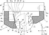
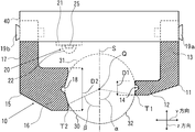
- FIG. 12 is an explanatory cross-sectional view showing an enlarged lens holding mechanism in the light irradiation device shown in FIG. 11.
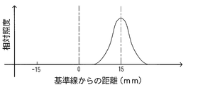
- 6 is a graph showing an illuminance distribution in the y direction by the light irradiation apparatus according to Example 1.
- 6 is a graph showing the illuminance distribution in the y direction by the light irradiation apparatus according to Examples 2 to 3 and Reference Example 1.
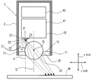
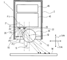
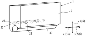
- FIG. 1 is a perspective view showing a configuration of an example of a light irradiation apparatus according to the first invention by cutting a housing.
- FIG. 2 is an explanatory view showing a configuration of an example of the light irradiation apparatus according to the first invention, with a housing cut.
- an x direction, a y direction, and a z direction indicated by arrows are three directions orthogonal to each other.
- the light irradiation apparatus 1 according to the first invention has a rectangular parallelepiped housing 2 whose bottom surface is open.
- the casing 2 in the illustrated example has a top surface and a bottom surface that are planar in the x direction (direction perpendicular to the paper surface in FIG. 2) and the y direction, and two of the four side surfaces facing each other are in the x direction and the z direction.
- a plane extending in the direction and other two side surfaces facing each other are a plane extending in the y direction and the z direction.
- a long light source 20 extending in the x direction is provided inside the housing 2.
- a columnar lens 30 having a long shape extending along the light source unit 20 is provided obliquely below the light source unit 20.
- a lens holding mechanism 10 including a first holding tool 11 and a second holding tool 15 that sandwich the columnar lens 30 is provided in the opening of the housing 2.
- a heat sink 40 made of, for example, aluminum is provided on the upper surface of the light source unit 20. As shown in FIG. 3, the heat sink 40 is formed with a plurality of fins 41 protruding upward.
- a cooling fan 45 is provided above the heat sink 40.
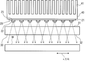
- the light source unit 20 has a long rectangular substrate 21.
- the substrate 21 is arranged in a posture extending in the x direction along a plane extending in the x direction and the y direction.
- a plurality of rectangular plate-like light emitting elements 25 are arranged in the x direction along the surface of the substrate 21, that is, a plane extending in the x direction and the y direction.
- Each of the light emitting elements 25 is provided with a hemispherical sealing lens 22 that covers the light emitting surface of the light emitting element 25 so as to protrude from the surface of the substrate 21.
- the light source part 20 is arrange
- a ceramic material such as aluminum nitride or alumina ceramic
- a composite resin material such as glass fiber reinforced epoxy resin, or the like
- glass materials such as quartz glass and borosilicate glass, or translucent resin materials, such as a silicone resin, an acrylic resin, and an epoxy resin, etc.
- translucent resin materials such as a silicone resin, an acrylic resin, and an epoxy resin, etc.
- the light emitting element 25 a light emitting diode that emits required light such as ultraviolet rays can be used.
- the columnar lens 30 in this example has a circular cross section perpendicular to the longitudinal direction.
- the columnar lens 30 has a light receiving surface 31 that receives light from the light source unit 20 in a region facing the light source unit 20 on the circumferential surface in the longitudinal direction (x direction), and the light receiving surface 31 on the circumferential surface.
- the opposite area has an emission surface 32 for emitting the received light.
- a region exposed upward from a first holder 11 and a second holder 15, which will be described later, serves as a light receiving surface 31, and from the first holder 11 and the second holder 15.
- a region exposed downward is an emission surface 32.
- the columnar lens 30 is arranged such that the emission surface 32 faces the irradiated surface W extending in the x direction and the y direction.
- a glass material such as quartz glass or borosilicate glass can be used.
- Each of the first holder 11 and the second holder 15 in the lens holding mechanism 10 has a long plate shape extending along the columnar lens 30, and has one longitudinal direction (x direction).
- the side surfaces are arranged so as to be opposed to each other.
- one side surface of each of the first holder 11 and the second holder 15 facing each other is a curved surface that matches a part of the circumferential surface of the columnar lens 30 in the longitudinal direction.
- the columnar lens 30 is sandwiched between one side of each of the first holder 11 and the second holder 15.
- the plane extended in the x direction and the z direction including the center P of the light emission surface of each light emitting element 25 is made into the light source reference plane F, and the central axis Q of the columnar lens 30 is made into the center axis
- the light source unit 20 is arranged so that the light source reference plane F is located on a plane separated from the lens reference plane S in the y direction.
- the second holder 15 in this example has a function as a light blocking body that blocks light from the light source unit 20.
- the second holder 15 is provided in a region opposite to the lens reference surface S with respect to the light source reference surface F.
- the second holder 15 is arranged so that the end on the lens reference surface S side in the y direction is positioned on the light source reference surface F or a plane separated from the light source reference surface F to the lens reference surface S side. .
- the second holder 15 that is a light blocking body. Is done.
- the light from the emission surface 32 of the columnar lens 30 is emitted in a direction inclined in a direction away from the light source reference surface F with respect to the z direction.
- the light from the output surface 32 of the columnar lens 30 is irradiated to the irradiated surface W extending in the x direction and the y direction.
- the separation distance between the light source reference surface F and the lens reference surface S is appropriately set according to the shape and dimensions of the columnar lens 30 and the second holder 15 which is a light shielding body, but the columnar shape in the y direction.
- the distance is preferably 0.3 to 1.5 times the distance from the central axis Q of the lens 30 to the peripheral surface on the light source reference plane F side (the radius of the columnar lens 30 in the illustrated example).
- an angle formed by a straight line connecting the center P of the light emitting surface of the light emitting element 25 and the center axis Q of the columnar lens 30 with respect to the lens reference surface S is, for example, 10 to 60 °.
- the light source unit 20 and the columnar lens 30 are arranged in a specific positional relationship, and the direction of light from the emission surface 32 of the columnar lens 30 is a light source reference with respect to the z direction. Since it inclines in the direction away from the surface F, it is possible to prevent or suppress light from being directly or indirectly irradiated to another part adjacent to one side (left side in FIG. 2). In addition, since it is not necessary to dispose the light irradiation device 1 far away from other adjacent parts, the overall size of the device can be reduced.
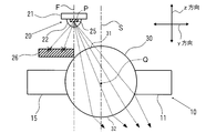
- FIG. 4 is an explanatory view showing a configuration of a main part in another example of the light irradiation apparatus of the first invention.
- each of the sealing lenses 22 provided in each of the light emitting elements 25 is in a plane in which the central axis L is translated from the light source reference plane F to the lens reference plane S side. It is formed to be positioned.
- Other configurations are the same as those of the light irradiation apparatus shown in FIGS.
- the separation distance between the central axis L of the sealing lens 22 and the light source reference plane F is appropriately set according to the dimensions of the light emitting element 25 and the sealing lens 22, but the radius of the sealing lens 22 is 0.3 to 0. .7 times is preferable.
- the same effect as the light irradiation apparatus shown in FIGS. 1 and 2 can be obtained.
- the central axis L of the sealing lens 22 is positioned in a plane translated from the light source reference surface F to the lens reference surface S side. Therefore, a part of the light traveling from the light emitting element 25 along the light source reference plane F and the light traveling in the direction away from the lens reference plane S with respect to the light source reference plane F is on the surface of the sealing lens 22. The light is refracted from F toward the lens reference surface S. Thereby, the quantity of the light shielded by the light shielding body among the light emitted from the light source unit 20 can be reduced. Therefore, it is possible to improve the light use efficiency.
- the thing of the structure clamped in the both ends of the longitudinal direction of the columnar lens 30 can be used instead of the elongate thing extended along the columnar lens 30, for example.
- a light shielding body 26 having a long shape extending in the direction may be provided.
- the second holder 15 does not need a function as the light shielding body 26, and thus, for example, a structure that is sandwiched at both ends in the longitudinal direction of the columnar lens 30 is used. be able to.
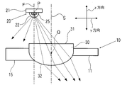
- the columnar lens 30 is not limited to a circular cross section, and various shapes can be used. Specifically, the columnar lens 30 is preferably one in which light is refracted in the direction away from the light source reference surface F at the light receiving surface 31 and the light emitting surface 32. For example, as shown in FIG. In this case, a configuration in which the emission surface 32 is a convex surface, or a configuration in which a part of the light receiving surface 31 is a convex surface and the emission surface 32 is a flat surface as shown in FIG.
- the light source unit 20 includes two substrates 21 each extending in the x direction (direction perpendicular to the paper surface in FIG. 8), and a plurality of substrates 21 are provided on each surface of the substrates 21.
- the light emitting elements 25 may be arranged in a state of being arranged in the x direction along the surface of the substrate 21.
- the light source reference plane F1 extending in the x direction and the z direction, including the center P1 of the light emitting surface of each light emitting element 25 arranged on one substrate 21, and the other
- Each of the light source reference planes F2 extending in the x direction and the z direction including the center P2 of the light emitting surface of each light emitting element disposed on the substrate 21 extends in the x direction and the z direction including the central axis Q of the columnar lens 30. What is necessary is just to be arrange
- a light reflecting member 27 can be provided between one side surface of the second holder 15 and the peripheral surface of the columnar lens 30.
- the light reflecting member 27 may be fixed to one side surface of the second holder 15 or may be fixed to the peripheral surface of the columnar lens 30.
- a material constituting the light reflecting member 27 a metal multilayer film deposited on the surface of a metal such as aluminum constituting the second holder 15, or a fluororesin such as polytetrafluoroethylene may be used. it can. According to such a configuration, the reflected light from the light reflecting member 27 proceeds in a direction inclined with respect to the lens reference surface S in a direction away from the light source reference surface F. Therefore, it is possible to improve the light use efficiency.
- a light absorbing member 28 may be formed between one side surface of the first holder 11 and the peripheral surface of the columnar lens 30.
- the light absorbing member 28 may be fixed to one side surface of the first holder 11 or may be fixed to the peripheral surface of the columnar lens 30.
- a material constituting the light absorbing member 28 a material obtained by black anodizing the surface of a metal such as aluminum constituting the first holder 11, or a fluororesin such as blackened polytetrafluoroethylene is used. Can do. According to such a configuration, the light from the columnar lens 30 is not reflected by one side surface of the first holder 11. For this reason, it is possible to prevent light traveling from the exit surface 32 of the columnar lens 30 in a direction inclined in a direction approaching the light source reference surface F with respect to the lens reference surface S.
- FIG. 11 is a perspective view showing the appearance of the light irradiation apparatus according to the first embodiment in the second invention
- FIG. 12 is an explanatory view showing the internal structure of the light irradiation apparatus shown in FIG. It is.
- an x direction, a y direction, and a z direction indicated by arrows are three directions orthogonal to each other.
- the housing 2 of the light irradiation device 1 has a top surface that is a plane extending in the x direction (direction perpendicular to the paper surface in FIG. 12) and the y direction, and two of the four side surfaces facing each other are in the x direction and the z direction.
- a plane extending in the direction and other two side surfaces facing each other are a plane extending in the y direction and the z direction.
- an opening for exposing an emission surface of a columnar lens 30 described later is formed on the lower surface of the housing 2, an opening for exposing an emission surface of a columnar lens 30 described later is formed.
- a long light source 20 extending in the x direction is provided inside the housing 2.
- a columnar lens 30 having a long shape extending along the light source unit 20 is provided obliquely below the light source unit 20.
- the light source unit 20 and the columnar lens 30 have the same configuration as the light source unit 20 and the columnar lens 30 in the light irradiation device 1 shown in FIG. 1 (see FIG. 3).
- a heat sink 40 made of, for example, aluminum is provided on the upper surface of the light source unit 20.
- the heat sink 40 is formed with a plurality of fins (not shown) that protrude upward.
- a cooling fan 41 (see FIG. 3) is provided above the heat sink 40.
- a lens holding mechanism 10 that holds the columnar lens 30 is provided on the lower surface of the heat sink 40.
- the lens holding mechanism 10 includes a first holding tool 11 and a second holding tool 15.
- the first holder 11 has one side of the lens reference plane S in the columnar lens 30 (the right side in FIG. 12). ) Is provided so as to be in contact with the peripheral surface region located at (1).
- the second holder 15 is provided so as to be in contact with a peripheral surface region located on the other side (left side in FIG. 12) of the lens reference surface S in the columnar lens 30.
- each of the first holder 11 and the second holder 15 is opposed to the columnar lens 30 extending in the x direction (direction perpendicular to the paper surface in FIG. 13) along the columnar lens 30. It has the clamping parts 12 and 16 which contact
- Each of the first holder 11 and the second holder 15 has a cantilever structure supported by the heat sink 40 at one end of the supported portions 13 and 17. In the illustrated example, the supported portions 13 and 17 of the first holder 11 and the second holder 15 are fixed at one end by bolts 19a and 19b.
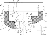
- grooves 14, extending in the x direction, are provided on the surfaces (hereinafter referred to as “contact surfaces”) in contact with the columnar lenses 30 in the sandwiching portions 12, 16 of the first holder 11 and the second holder 15. 18 is formed.
- the thickness d1 in the direction away from the center position of the groove 14 to the irradiated surface is greater than the thickness d2 in the direction approaching the irradiated surface from the center position of the bottom of the groove 14. Is also considered to be large.
- the thickness d3 in the direction away from the center position of the bottom of the groove 18 to the irradiated surface is the thickness in the direction approaching the irradiated surface from the central position of the groove 18. It is supposed to be smaller than d4.
- the second holder 15 is disposed so as to block light other than light traveling from the other side of the lens reference surface S toward one side of the lens reference surface S among the light from the light source unit 20. More specifically, when a light source reference plane F is a plane that includes the center P of the light emitting surface of the light emitting element 25 and extends in the x direction and the z direction, the light source unit 20 has the light source reference plane F as the lens reference plane S. It arrange
- the irradiated surface in the peripheral surface area where the second holder 15 of the columnar lens 30 contacts In the cross section perpendicular to the longitudinal direction (x direction) of the columnar lens 30 (hereinafter, also referred to as “yz cross section”), the irradiated surface in the peripheral surface area where the second holder 15 of the columnar lens 30 contacts.
- the second holder 15 When the position closest to the surface W is the position T2, the second holder 15 is disposed so that the position T2 is positioned on the light source reference surface F or a plane closer to the lens reference surface S than the light source reference surface F. ing.
- the second holder 15 is shielded by the second holder 15.
- the separation distance between the light source reference surface F and the lens reference surface S is appropriately set according to the shape and dimensions of the columnar lens 30 and the second holder 15, but the center of the columnar lens 30 in the y direction. It is preferably 0.3 to 1.5 times the distance from the axis Q to the peripheral surface on the other side (in the example shown, the radius of the columnar lens 30). Further, an angle formed by a straight line connecting the center P of the light emitting surface of the light emitting element 25 and the center axis Q of the columnar lens 30 with respect to the lens reference surface S is, for example, 10 to 60 °. Further, the contact surfaces of the first holding tool 11 and the second holding tool 15 do not need to contact the columnar lens 30 over the entire surface. For example, in the yz cross section, the contact surfaces may contact each other at two or more points, for example. Good.
- the first holder 11 has an angle ⁇ formed by a straight line connecting the position Q and the position T1 with respect to the lens reference plane S and an angle ⁇ formed by a straight line connecting the position Q and the position T2 with respect to the lens reference plane S. It is arranged to be larger.
- the position Q is the position of the central axis of the columnar lens 30
- the position T1 is the position closest to the irradiated surface W in the peripheral surface area where the first holder 11 contacts the columnar lens 30.
- the position T2 is the position closest to the irradiated surface W in the peripheral surface area where the second holder 15 in the columnar lens 30 contacts.
- the thicknesses of the sandwiching portions 12 and 16 in the z direction are the same, and the supported portion 13 of the first holding tool 11 is in the z direction.
- the size is smaller than the size in the z direction of the supported portion 17 of the second holder 15.
- the clamping part 12 of the 1st holder 11 is arrange
- the 1st holder 11 is arrange
- the angle ⁇ formed is preferably 70 to 90 °.
- the difference between the formed angle ⁇ and the formed angle ⁇ is preferably 25 to 80 °.
- the lens reference surface S is formed from the emission surface 32 of the columnar lens 30.
- Light is emitted in the direction from the other side to the one side, and all or most of the light other than the light traveling from the other side of the lens reference surface S toward the one side is shielded by the second holder 15. Therefore, it is possible to prevent or suppress light from being irradiated to other parts adjacent to the other side of the lens reference surface S.
- the overall size of the device can be reduced.
- the light utilization efficiency can be improved.
- first holding tool 11 and the second holding tool 15 have a cantilever structure supported at one end of the supported portions 13 and 17, the first holding tool 12 and the second holding tool 15
- the columnar lens 30 is held at each free end. For this reason, the bending amount of the supported parts 13 and 17 can be adjusted. Accordingly, even if the center axis of the columnar lens 30 is displaced, this can be easily adjusted. More specifically, the positions of the end portions of the first holding tool 11 and the second holding tool 15 are adjusted by the members fixing the heat holding member 40 to the heat sink 40, for example, the rotational speed of the bolts 19a and 19b, the tightening degree, and the like. be able to.
- the position of the columnar lens 30 can be adjusted by adjusting the positions of the end portions of the first holder 11 and the second holder 15. Further, by sandwiching the columnar lens 30 on the upper side and the lower side of the groove 18 provided in the clamping unit 16 and holding the columnar lens 30 on one side two tangents, the positional deviation of the central axis of the columnar lens 30 can be further suppressed.
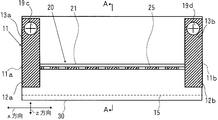
- FIG. 14 is an explanatory diagram showing the internal configuration of the light irradiation apparatus according to the second embodiment of the second invention
- FIG. 15 is a cross-sectional view taken along the line AA of the light irradiation apparatus shown in FIG.
- the first holder 11 is constituted by two holding members 11a and 11b that hold the columnar lens 30 at both ends in the longitudinal direction (x direction).
- One holding member 11a includes a sandwiching portion 12a that is in contact with one end of the columnar lens 30, and a supported portion 13a that is coupled to the sandwiching portion 12a.
- the other holding member 11b includes a sandwiching portion 12b that contacts the other end portion of the columnar lens 30, and a supported portion 13b that is coupled to the sandwiching portion 12b.
- a groove (not shown) extending in the x direction is formed on the contact surface of the holding portion 12a of one holding member 11a.
- a groove 14b extending in the x direction is formed on the contact surface of the holding portion 12b of the other holding member 11b.
- the supported portions 13a and 13b are fixed to the heat sink 40 by bolts 19c and 19d.
- the other structure in this light irradiation apparatus is the same as that of the light irradiation apparatus shown in FIG. 11 and FIG.
- the same effect as the light irradiation apparatus shown in FIGS. 11 and 12 can be obtained.
- the first holder 11 is configured to contact at both ends in the longitudinal direction of the columnar lens 30, light that is shielded by the first holder 11 among light emitted from the light source unit 20. The amount of can be reduced. Therefore, it is possible to improve the light use efficiency.
- FIG. 16 is an explanatory diagram showing the internal configuration of the light irradiation apparatus according to the third embodiment of the second invention.
- each of the sealing lenses 22 provided in each of the light emitting elements 25 is in a plane in which the central axis L is translated from the light source reference plane F to the lens reference plane S side. It is formed to be positioned. That is, each central axis L of the sealing lens 22 is separated to the lens reference surface S side so that the position differs from the light source reference surface F related to the corresponding light emitting element 25.
- the other structure in this light irradiation apparatus is the same as that of the light irradiation apparatus shown in FIG. 11 and FIG.
- the separation distance between the central axis L of the sealing lens 22 and the light source reference plane F is appropriately set according to the dimensions of the light emitting element 25 and the sealing lens 22, but the radius of the sealing lens 22 is 0.3 to 0. .7 times is preferable.
- the same effect as the light irradiation apparatus shown in FIGS. 11 and 12 can be obtained.
- the central axis L of the sealing lens 22 is positioned in a plane closer to the lens reference surface S than the light source reference surface F. Therefore, a part of the light traveling from the light emitting element 25 along the light source reference plane F and the light traveling in the direction away from the lens reference plane S with respect to the light source reference plane F is on the surface of the sealing lens 22. The light is refracted from F toward the lens reference surface S. Thereby, the amount of light shielded by the second holder 15 among the light emitted from the light source unit 20 can be reduced. Therefore, it is possible to improve the light use efficiency.
- FIG. 17 is an explanatory diagram showing the internal configuration of the light irradiation apparatus according to the fourth embodiment of the second invention.
- a reflecting mirror 35 extending in the x direction (direction perpendicular to the paper surface in FIG. 17) is provided along the longitudinal direction of the columnar lens 30 on the other side of the lens reference surface S of the columnar lens 30.
- the reflecting surface 35 a is disposed so as to face the columnar lens 30 so that it receives light from the light source unit 20 and reflects it to one side of the lens reference surface S via the columnar lens 30.
- a columnar support base 36 extending in the x direction and having a substantially trapezoidal cross section is provided in the longitudinal direction of the second holder 15.
- a surface of the support base 36 facing the columnar lens 30 is a support surface 36 a that supports the reflecting mirror 35.
- the support surface 36a is formed in an inclined state with respect to the lens reference surface S so as to approach the lens reference surface S as it goes from the light source unit 20 side to the clamping unit 16 side of the second holding unit 15.
- the reflecting mirror 35 is supported in a state where the back surface thereof is in contact with the support surface 36 a of the support base 36.
- the reflecting surface 35a of the reflecting mirror 35 is inclined with respect to the lens reference surface S so as to approach the lens reference surface S from the light source unit 20 side toward the clamping unit 16 side of the second holding unit 15. Thus, it is arranged to face the columnar lens 30.
- the reflecting mirror 35 is disposed in a state where one side edge extending in the x direction on the reflecting surface 35 a is in contact with the outer peripheral surface of the columnar lens 30.
- a mirror in which a metal multilayer film is formed on the surface of a substrate made of aluminum by vapor deposition or the like can be used.
- the other structure in this light irradiation apparatus is the same as that of the light irradiation apparatus shown in FIG. 11 and FIG.
- the same effect as the light irradiation apparatus shown in FIGS. 11 and 12 can be obtained.
- this light irradiation device light traveling from the light emitting element 25 in a direction away from the lens reference surface S with respect to the light source reference surface F is reflected on the lens reference surface S by the reflecting mirror 35 via the columnar lens 30. Reflects to one side. Thereby, the amount of light shielded by the second holder 15 among the light emitted from the light source unit 20 can be reduced. Therefore, it is possible to improve the light use efficiency.
- the columnar lens 30 is not limited to a circular cross section, and various shapes can be used. However, the columnar lens 30 is preferably one that refracts light in the direction away from the light source reference surface F on the light receiving surface 31 and the light emitting surface 32.
- the light source unit 20 includes two substrates 21 extending in the x direction, and a plurality of light emitting elements 25 are arranged in the x direction along the surface of the substrate 21 on each surface of the substrates 21. It may be arranged in an open state.
- Specific forms of the first holding tool 11 and the second holding tool 15 are not limited to those shown in FIG.
- the sandwiching portions 12 and 16 have asymmetric shapes. Specifically, the sandwiching portion 12 of the first holder 11 has a thickness D1 in the z direction smaller than the thickness D2 in the z direction of the sandwiching portion 16 of the second holder 15. Further, a groove extending in the x direction (a direction perpendicular to the paper surface in FIG. 18) is formed at the center position in the z direction on the contact surfaces of the holding portions 12 and 16 of the first holding tool 11 and the second holding tool 15. 14 and 18 are formed.
- FIG. 19 is an explanatory diagram showing an outline of a configuration in an example of the photocuring material processing apparatus of the present invention.
- This photocuring material processing apparatus is configured as an ink jet printer, and has a rectangular parallelepiped shape including a plurality of ejection units (not shown) that eject ultraviolet curable ink, which is a photocuring material, onto a recording medium M.
- a head unit 50 is provided.
- a light irradiation device 1 for irradiating the photocurable material discharged onto the recording medium M with ultraviolet rays is disposed adjacent to the head unit 50 on each side of the head unit 50.
- This light irradiation apparatus 1 is the light irradiation apparatus of the first invention or the second invention described above. Further, with reference to FIG. 2, each of the light irradiation devices 1 is arranged so that light from the emission surface 32 of the columnar lens 30 is irradiated to a position away from the head unit 50. Specifically, each of the light irradiation devices 1 is arranged in a posture in which a side surface located on the other side of the lens reference surface S (see FIG. 2) in the housing 2 is close to the head unit 50. Each of the head unit 50 and the light irradiation device 1 is supported by a guide rail 55 extending in the y direction so as to be movable in the y direction.
- the recording medium M is intermittently conveyed in the x direction by appropriate conveying means (not shown). Then, while moving the head unit 50 in the y direction, ink is ejected from the ejection unit of the head unit 50 toward the conveyed recording medium M. Thereby, ink adheres to the recording medium M. Thereafter, the ink attached to the recording medium M is irradiated with light by the light irradiation device 1, whereby the ink is cured and fixed to the recording medium M.
- a photo-curing material processing apparatus According to such a photo-curing material processing apparatus, light from the exit surface 32 of the columnar lens 30 in each of the light irradiation devices 1 is irradiated to a position separated from the head unit 50, so that the discharge unit of the head unit 50 is irradiated with light. Irradiation with light can be prevented or suppressed. In addition, since it is not necessary to dispose each of the light irradiation devices 1 separately from the head unit 50, the entire photocuring material processing device can be reduced in size.
- Example 1 Except that the sealing lens was formed according to the configuration shown in FIG. 4, a light irradiation device having the following specifications was produced according to the configuration shown in FIGS. 1 and 2.
- the substrate in the light source unit is made of aluminum nitride and has dimensions of 105 mm ⁇ 20 mm ⁇ 1.0 mm.
- the light emitting element is a light emitting diode having a peak wavelength of 395 nm, an output of 700 mW, and a size of 1.0 mm ⁇ 1.0 mm ⁇ 0.1 mm.
- the number of light emitting elements is 25, and the arrangement pitch is 4.0 mm.
- the sealing lens is made of a silicone resin, has a radius of 1.1 mm, and is formed so that the distance between the central axis L and the light source reference surface F is 0.5 mm.
- the columnar lens is made of quartz glass, has a total length of 110 mm, a diameter of 10 mm, a distance between the light source reference surface F and the lens reference surface S is 5 mm, and the columnar shape of the light emitting surface center P of the light emitting element with respect to the lens reference surface S.
- the angle formed by the straight line connecting the center axis Q of the lens with the shortest angle is 45 °.
- the first holder and the second holder are made of aluminum and the total length is 110 mm. Further, the second holder is arranged so that the end portion on the lens reference surface S side in the y direction is positioned on the light source reference surface F.
- the illuminance peak is at a position 15 mm away from the lens reference surface S in the direction opposite to the light source reference surface F in the y direction of the irradiated surface.
- An irradiation region having the following is formed. Further, it was confirmed that the illuminance of the region on the light source reference surface F side from the lens reference surface S is substantially zero in the y direction of the irradiated surface. From the above, according to the above-described light irradiation device, it is possible to prevent or suppress light from being directly or indirectly irradiated to another part adjacent to one side.
- Example 2 Except that the sealing lens was formed according to the configuration shown in FIG. 16, a light irradiation device having the following specifications was manufactured according to the configuration shown in FIGS. 11 and 12.
- the substrate in the light source unit is made of aluminum nitride and has dimensions of 105 mm ⁇ 20 mm ⁇ 1.0 mm.
- the light emitting element is a light emitting diode having a peak wavelength of 395 nm, an output of 700 mW, and a size of 1.0 mm ⁇ 1.0 mm ⁇ 0.1 mm.
- the number of light emitting elements is 25, and the arrangement pitch is 4.0 mm.
- the sealing lens is made of a silicone resin, has a radius of 1.1 mm, and is formed so that the distance between the central axis L and the light source reference surface F is 0.5 mm.
- the columnar lens is made of quartz glass, has a total length of 110 mm, and a diameter of 10 mm.
- the first holder and the second holder are made of aluminum, the total length is 108 mm, and the thickness in the z direction of each clamping portion is 4 mm.
- a groove having a semicircular cross section is formed on the contact surface of each clamping portion, and the radius thereof is 0.5 mm.
- the thickness (d1) in the direction away from the central position of the groove to the irradiated surface is 3 mm
- the thickness (d2) in the direction of approaching the irradiated surface from the central position of the bottom of the groove is 1 mm.
- the thickness (d3) in the direction away from the central position of the groove to the irradiated surface is 1 mm
- the thickness (d4) in the direction approaching the irradiated surface from the central position of the bottom of the groove is 3 mm. .
- the light source unit, the columnar lens, and the lens holding mechanism are arranged in a positional relationship that satisfies the following conditions.
- the separation distance between the light source reference surface F and the lens reference surface S is 5 mm.
- An angle formed by a straight line connecting the center P of the light emitting surface of the light emitting element with respect to the lens reference surface S and the center axis Q of the columnar lens is 45 °.
- the second holder is arranged so that the position T2 is located on the light source reference plane F.
- An angle ⁇ formed by a straight line connecting the position Q and the position T1 with respect to the lens reference surface S is 85 °
- an angle ⁇ formed by a straight line connecting the position Q and the position T2 with respect to the lens reference surface S is 50 °.
- Example 3 A light irradiation apparatus having the same specifications as in Example 2 was produced except that a reflecting mirror was provided according to the configuration shown in FIG.
- the reflecting mirror in this light irradiation apparatus is formed by forming a metal multilayer film on the surface of a substrate made of aluminum by vapor deposition or the like.
- the size of the reflecting mirror is 108 mm ⁇ 3.5 mm ⁇ 0.5 mm.
- the reflecting mirror is arranged such that the angle of inclination of the reflecting surface with respect to the lens reference surface S is 12.5 ° in a state where one side edge extending in the x direction on the reflecting surface is in contact with the outer peripheral surface of the columnar lens. Yes.
- Example 1 A light irradiation device having the same specifications as in Example 2 was produced, except that the first holder was changed to a shape symmetrical to the second holder with respect to the lens reference surface S.
- an illuminance peak is generated at a position 15 mm away from the lens reference surface S on the one side in the y direction of the irradiated surface.
- An irradiation region is formed.
- the illuminance of the region on the other side of the lens reference surface S is substantially zero in the y direction of the irradiated surface.
- the value of the maximum illuminance by the light irradiation apparatus according to Example 2 is 1.1 times the value of the maximum illuminance by the light irradiation apparatus according to Reference Example 1
- the maximum illuminance value by the light irradiation apparatus according to Example 3 is The value was 1.26 times the value of the integrated light amount by the light irradiation apparatus according to Reference Example 1.
- the value of the integrated light amount by the light irradiation apparatus according to Example 2 is 1.156 times the value of the integrated light quantity by the light irradiation apparatus according to Reference Example 1, and the integrated light amount by the light irradiation apparatus according to Example 3 is obtained.
- the value was 1.51 times the value of the integrated light quantity by the light irradiation device according to Reference Example 1. From the above, the light irradiation apparatus according to Example 3 has higher light use efficiency than the light irradiation apparatus according to Reference Example 1, and the light irradiation apparatus according to Example 3 It was confirmed that the light use efficiency was higher than that of the light irradiation apparatus according to Example 2.
Landscapes
- Engineering & Computer Science (AREA)
- Mechanical Engineering (AREA)
- Chemical & Material Sciences (AREA)
- Manufacturing & Machinery (AREA)
- Materials Engineering (AREA)
- Non-Portable Lighting Devices Or Systems Thereof (AREA)
Abstract
隣接する他の部位への光の照射が防止または抑制され、装置全体の小型化が可能な光照射装置およびこの光照射装置を備えた光硬化材料処理装置を提供する。 本発明の光照射装置は、互いに直交する3つの方向をx方向、y方向、z方向としたとき、複数の発光素子がx方向およびy方向に伸びる平面に沿ってx方向に並んだ状態で配置された長尺な光源部と、光源部に沿ってx方向に伸びる長尺な形状を有し、その長手方向の周面に、光源部からの光を受光する受光面および受光した光を出射する出射面を有する柱状レンズとを備え、光源部は、各発光素子の発光面の中心を含む、x方向およびz方向に伸びる光源基準面が、柱状レンズの中心軸を含む、x方向およびz方向に伸びるレンズ基準面に対してy方向に離間した平面に位置するよう配置され、柱状レンズの出射面からの光の方向が、レンズ基準面に対して光源基準面から離間する方向に傾斜している。
Description
本発明は、例えばインクジェットプリンタや3Dプリンタなどに搭載される光照射装置およびこの光照射装置を備えた光硬化材料処理装置に関する。
従来、印刷分野や電子工業分野などにおいては、処理対象物、例えば保護膜、接着剤、塗料、インク、フォトレジスト、樹脂、配向膜等に対して、硬化処理、乾燥処理、溶融処理、軟化処理、或いは改質処理などを行うために、特定の波長の光を放射する光照射装置が多用されている。
例えば、特許文献1には、紫外線硬化型のインクを用いたインクジェットプリンタが開示されている。このインクジェットプリンタには、インクを射出するヘッド部と、このヘッド部に隣接して設置された光照射装置とが搭載されている。このようなインクジェットプリンタにおいては、ヘッド部には複数の吐出部が設けられている。そして、これらの吐出部から種々のインク(光硬化材料)が記録媒体に射出される。その後、記録媒体に射出されたインクに対して、光照射装置によって光が照射される。
しかしながら、上記のインクジェットプリンタにおいては、長期間使用すると、吐出部からのインクの射出量が不安定になることがある。このような現象が生じる一因は、ヘッド部に隣接して配置された光照射装置からの光が、当該ヘッド部における吐出部に直接ないし間接的に照射されることにより、吐出部においてインクが硬化し、その硬化物によって吐出部からのインクの射出が阻害されるためである。
特に、3Dプリンタを代表とする光造形装置においては、被照射面に立体構造物が形成される。そのため、得られる立体構造物によって光照射装置からの光が反射されることにより、その反射光が、ヘッド部における吐出部に照射されやすくなる。その結果、吐出部からの光硬化性材料の射出量が不安定になる現象が生じやすい、という問題がある。
特に、3Dプリンタを代表とする光造形装置においては、被照射面に立体構造物が形成される。そのため、得られる立体構造物によって光照射装置からの光が反射されることにより、その反射光が、ヘッド部における吐出部に照射されやすくなる。その結果、吐出部からの光硬化性材料の射出量が不安定になる現象が生じやすい、という問題がある。
このような問題を解決するため、特許文献2には、光照射装置を、ヘッド部から距離Lだけ離間させると共に、当該光照射装置を傾斜させて配置することにより、光照射装置からの光が、当該ヘッド部における吐出部に照射されることを抑制するインクジェットプリンタが開示されている。
しかしながら、このインクジェットプリンタにおいては、光照射装置をヘッド部から相当に大きく離間させると共に傾斜して配置するため、装置全体が大型のものとなる、という問題がある。
しかしながら、このインクジェットプリンタにおいては、光照射装置をヘッド部から相当に大きく離間させると共に傾斜して配置するため、装置全体が大型のものとなる、という問題がある。
そこで、本発明の目的は、隣接する他の部位に光が照射されることを防止または抑制することができ、しかも、装置全体の小型化を図ることができる光照射装置およびこの光照射装置を備えた光硬化材料処理装置を提供することにある。
本発明において、第1の発明の光照射装置は、互いに直交する3つの方向をx方向、y方向およびz方向としたとき、
複数の発光素子がx方向およびy方向に伸びる平面に沿ってx方向に並んだ状態で配置されてなる長尺な光源部と、
前記光源部に沿ってx方向に伸びる長尺な形状を有し、その長手方向の周面に、前記光源部からの光を受光する受光面および受光した光を出射する出射面を有する柱状レンズとを備えてなり、
前記発光素子の各々の発光面の中心を含む、x方向およびz方向に伸びる平面を光源基準面とし、前記柱状レンズの中心軸を含む、x方向およびz方向に伸びる平面をレンズ基準面としたとき、
前記光源部は、前記光源基準面が前記レンズ基準面に対してy方向に離間した平面に位置するよう配置されており、
前記柱状レンズの出射面からの光の方向が、前記レンズ基準面に対して前記光源基準面から離間する方向に傾斜していることを特徴とする。
複数の発光素子がx方向およびy方向に伸びる平面に沿ってx方向に並んだ状態で配置されてなる長尺な光源部と、
前記光源部に沿ってx方向に伸びる長尺な形状を有し、その長手方向の周面に、前記光源部からの光を受光する受光面および受光した光を出射する出射面を有する柱状レンズとを備えてなり、
前記発光素子の各々の発光面の中心を含む、x方向およびz方向に伸びる平面を光源基準面とし、前記柱状レンズの中心軸を含む、x方向およびz方向に伸びる平面をレンズ基準面としたとき、
前記光源部は、前記光源基準面が前記レンズ基準面に対してy方向に離間した平面に位置するよう配置されており、
前記柱状レンズの出射面からの光の方向が、前記レンズ基準面に対して前記光源基準面から離間する方向に傾斜していることを特徴とする。
第1の発明の光照射装置においては、前記光源基準面に対して前記レンズ基準面とは反対側の領域に、前記光源部からの光を遮光する遮光体が設けられていることが好ましい。
このような光照射装置においては、前記遮光体における前記レンズ基準面側の端部が、前記光源基準面または当該光源基準面よりレンズ基準面側に離間した平面内に位置されていることが好ましい。
このような光照射装置においては、前記遮光体における前記レンズ基準面側の端部が、前記光源基準面または当該光源基準面よりレンズ基準面側に離間した平面内に位置されていることが好ましい。
また、第1の発明の光照射装置においては、前記光源部における前記発光素子の各々には、当該発光素子の発光面を覆う半球形状の封止レンズが設けられており、前記封止レンズの中心軸が前記光源基準面から前記レンズ基準面側に並進した平面内に位置されていることが好ましい。
本発明において、第2の発明の光照射装置は、互いに直交する3つの方向をx方向、y方向およびz方向としたとき、
複数の発光素子がx方向およびy方向に伸びる平面に沿ってx方向に並んだ状態で配置されてなる長尺な光源部と、
前記光源部に沿ってx方向に伸びる長尺な形状を有し、その長手方向の周面に、前記光源部からの光を受光する受光面および受光した光を出射する出射面を有する柱状レンズと、
第1の保持具および第2の保持具よりなり、前記第1の保持具および前記第2の保持具の間に前記柱状レンズを挟持するレンズ保持機構とを備えてなり、
前記柱状レンズの出射面からの光を、x方向およびy方向に伸びる被照射面に照射する光照射装置であって、
前記柱状レンズの中心軸を含む、x方向およびz方向に伸びる平面をレンズ基準面としたとき、
前記第1の保持具は、前記柱状レンズにおける前記レンズ基準面の一側に位置する周面領域に対接するよう設けられ、前記第2の保持具は、前記柱状レンズにおける前記レンズ基準面の他側に位置する周面領域に対接するよう設けられており、
前記柱状レンズの長手方向に垂直な断面において、
前記柱状レンズの中心軸の位置を位置Q、前記柱状レンズにおける前記第1の保持具が対接する周面領域のうち、前記被照射面に最も接近した位置を位置T1、前記柱状レンズにおける前記第2の保持具が対接する周面領域のうち、前記被照射面に最も接近した位置を位置T2としたとき、
前記第1の保持具は、レンズ基準面Sに対する位置Qおよび位置T1を結ぶ直線のなす角αが、レンズ基準面Sに対する位置Qおよび位置T2を結ぶ直線のなす角βより大きくなるよう配置されていることを特徴とする。
複数の発光素子がx方向およびy方向に伸びる平面に沿ってx方向に並んだ状態で配置されてなる長尺な光源部と、
前記光源部に沿ってx方向に伸びる長尺な形状を有し、その長手方向の周面に、前記光源部からの光を受光する受光面および受光した光を出射する出射面を有する柱状レンズと、
第1の保持具および第2の保持具よりなり、前記第1の保持具および前記第2の保持具の間に前記柱状レンズを挟持するレンズ保持機構とを備えてなり、
前記柱状レンズの出射面からの光を、x方向およびy方向に伸びる被照射面に照射する光照射装置であって、
前記柱状レンズの中心軸を含む、x方向およびz方向に伸びる平面をレンズ基準面としたとき、
前記第1の保持具は、前記柱状レンズにおける前記レンズ基準面の一側に位置する周面領域に対接するよう設けられ、前記第2の保持具は、前記柱状レンズにおける前記レンズ基準面の他側に位置する周面領域に対接するよう設けられており、
前記柱状レンズの長手方向に垂直な断面において、
前記柱状レンズの中心軸の位置を位置Q、前記柱状レンズにおける前記第1の保持具が対接する周面領域のうち、前記被照射面に最も接近した位置を位置T1、前記柱状レンズにおける前記第2の保持具が対接する周面領域のうち、前記被照射面に最も接近した位置を位置T2としたとき、
前記第1の保持具は、レンズ基準面Sに対する位置Qおよび位置T1を結ぶ直線のなす角αが、レンズ基準面Sに対する位置Qおよび位置T2を結ぶ直線のなす角βより大きくなるよう配置されていることを特徴とする。
第2の発明の光照射装置においては、前記光源部における前記発光素子の発光面の中心が、前記レンズ基準面よりも他側に配置されていることが好ましい。
また、前記柱状レンズにおける前記レンズ基準面の他側には、前記光源部よりの光を受け、前記柱状レンズを介して、前記レンズ基準面の一側に反射する反射鏡が、前記柱状レンズの長手方向に沿って設けられていることが好ましい。
また、前記第1の保持具は、前記柱状レンズの長手方向の端部において対接していることが好ましい。
また、前記第1の保持具および前記第2の保持具の各々は、前記柱状レンズに対接する挟持部と、前記挟持部に連結された、x方向に伸びる被支持部とを備えてなり、前記被支持部の一端部において支持されるカンチレバー構造を有することが好ましい。
また、前記柱状レンズにおける前記レンズ基準面の他側には、前記光源部よりの光を受け、前記柱状レンズを介して、前記レンズ基準面の一側に反射する反射鏡が、前記柱状レンズの長手方向に沿って設けられていることが好ましい。
また、前記第1の保持具は、前記柱状レンズの長手方向の端部において対接していることが好ましい。
また、前記第1の保持具および前記第2の保持具の各々は、前記柱状レンズに対接する挟持部と、前記挟持部に連結された、x方向に伸びる被支持部とを備えてなり、前記被支持部の一端部において支持されるカンチレバー構造を有することが好ましい。
本発明の光硬化材料処理装置は、光硬化材料を吐出する吐出部を備えたヘッド部と、前記ヘッド部に隣接して設けられた、上記の光照射装置とを備えてなり、
前記光照射装置は、前記柱状レンズの出射面からの光が前記ヘッド部から離間する位置に照射されるよう配置されていることを特徴とする。
前記光照射装置は、前記柱状レンズの出射面からの光が前記ヘッド部から離間する位置に照射されるよう配置されていることを特徴とする。
第1の発明の光照射装置によれば、光源部および柱状レンズが特定の位置関係で配置されており、柱状レンズの出射面からの光の方向が、レンズ基準面に対して光源基準面から離間する方向に傾斜しているため、隣接する他の部位に光が照射されることを防止または抑制することができる。しかも、隣接する他の部位に対して、光照射装置を離間して配置することが不要であるため、装置全体の小型化を図ることができる。
第2の発明の光照射装置によれば、柱状レンズの出射面から、レンズ基準面の他側から一側に向かう方向に光が出射され、第2の保持具によってレンズ基準面の他側から一側に向かって進む光以外の光の全部または大部分が遮光される。そのため、レンズ基準面の他側に隣接する他の部位に光が照射されることを防止または抑制することができる。しかも、隣接する他の部位に対して、光照射装置を離間して配置することが不要であるため、装置全体の小型化を図ることができる。
以下、本発明の実施の形態について説明する。
〈第1の発明〉
図1は、第1の発明に係る光照射装置の一例における構成を、筐体を切断して示す斜視図である。図2は、第1の発明に係る光照射装置の一例における構成を、筐体を切断して示す説明図である。図において、 それぞれ矢印で示すx方向、y方向およびz方向は、互いに直交する3つの方向である。
この第1の発明に係る光照射装置1は、下面が開口する直方体状の筐体2を有する。図示の例の筐体2は、上面および下面がx方向(図2において紙面に垂直な方向)およびy方向に伸びる平面とされ、4つの側面のうち互いに対向する2つの側面がx方向およびz方向に伸びる平面、その他の互いに対向する2つの側面がy方向およびz方向に伸びる平面とされている。
〈第1の発明〉
図1は、第1の発明に係る光照射装置の一例における構成を、筐体を切断して示す斜視図である。図2は、第1の発明に係る光照射装置の一例における構成を、筐体を切断して示す説明図である。図において、 それぞれ矢印で示すx方向、y方向およびz方向は、互いに直交する3つの方向である。
この第1の発明に係る光照射装置1は、下面が開口する直方体状の筐体2を有する。図示の例の筐体2は、上面および下面がx方向(図2において紙面に垂直な方向)およびy方向に伸びる平面とされ、4つの側面のうち互いに対向する2つの側面がx方向およびz方向に伸びる平面、その他の互いに対向する2つの側面がy方向およびz方向に伸びる平面とされている。
筐体2の内部には、x方向に伸びる長尺な光源部20が設けられている。光源部20の斜め下方には、光源部20に沿って伸びる長尺な形状を有する柱状レンズ30が設けられている。筐体2の開口には、それぞれ柱状レンズ30を挟持する第1の保持具11および第2の保持具15よりなるレンズ保持機構10が設けられている。光源部20の上面には、例えばアルミニウムよりなるヒートシンク40が設けられている。このヒートシンク40には、図3にも示すように、それぞれ上方に突出する複数のフィン41が形成されている。また、ヒートシンク40の上方には、冷却ファン45が設けられている。
光源部20は、長尺な矩形の基板21を有する。この基板21は、x方向およびy方向に伸びる平面に沿って、当該x方向に伸びる姿勢で配置されている。基板21の表面(図2において下面)には、矩形の板状の複数の発光素子25が、当該基板21の表面すなわちx方向およびy方向に伸びる平面に沿ってx方向に並んだ状態で配置されている。発光素子25の各々には、当該発光素子25の発光面を覆う半球形状の封止レンズ22が、基板21の表面から突出するよう設けられている。そして、光源部20は、各発光素子25の発光面が下方を向く姿勢で配置されている。
光源部20において、基板21を構成する材料としては、窒化アルミニウム、アルミナセラミックス等のセラミックス材料、ガラス繊維補強型エポキシ樹脂等の複合樹脂材料などを用いることができる。
また、封止レンズ22を構成する材料としては、石英ガラス、ホウ珪酸ガラス等のガラス材料、あるいは、シリコーン樹脂、アクリル樹脂、エポキシ樹脂などの透光性樹脂材料などを用いることができる。
また、発光素子25としては、所要の光例えば紫外線を出射する発光ダイオードを用いることができる。
また、封止レンズ22を構成する材料としては、石英ガラス、ホウ珪酸ガラス等のガラス材料、あるいは、シリコーン樹脂、アクリル樹脂、エポキシ樹脂などの透光性樹脂材料などを用いることができる。
また、発光素子25としては、所要の光例えば紫外線を出射する発光ダイオードを用いることができる。
この例の柱状レンズ30は、長手方向に垂直な断面が円形のものである。柱状レンズ30は、その長手方向(x方向)の周面における光源部20に対向する領域に、当該光源部20からの光を受光する受光面31を有し、当該周面における受光面31と反対側の領域に、受光された光を出射する出射面32を有する。図示の柱状レンズ30においては、後述する第1の保持具11および第2の保持具15から上方に露出する領域が受光面31とされ、第1の保持具11および第2の保持具15から下方に露出する領域が出射面32とされている。そして、柱状レンズ30は、出射面32がx方向およびy方向に伸びる被照射面Wに臨むよう配置されている。
柱状レンズ30を構成する材料としては、石英ガラスやホウ珪酸ガラスなどのガラス材料を用いることができる。
柱状レンズ30を構成する材料としては、石英ガラスやホウ珪酸ガラスなどのガラス材料を用いることができる。
レンズ保持機構10における第1の保持具11および第2の保持具15の各々は、柱状レンズ30に沿って伸びる長尺な板状の形状を有し、それぞれの長手方向(x方向)の一側面が互いに離間して対向するよう配置されている。図示の例では、第1の保持具11および第2の保持具15の各々における互いに対向する一側面は、柱状レンズ30の長手方向の周面の一部に適合する曲面とされている。そして、柱状レンズ30は、第1の保持具11および第2の保持具15の各々の一側面の間に挟持されている。
そして、第1の発明の光照射装置1においては、各発光素子25の発光面の中心Pを含む、x方向およびz方向に伸びる平面を光源基準面Fとし、柱状レンズ30の中心軸Qを含む、x方向およびz方向に伸びる平面をレンズ基準面Sとしたとき、光源部20は、光源基準面Fがレンズ基準面Sに対してy方向に離間した平面に位置するよう配置されている。また、この例における第2の保持具15は、光源部20からの光を遮光する遮光体としての機能を有する。具体的に説明すると、第2の保持具15は、光源基準面Fに対してレンズ基準面Sとは反対側の領域に設けられている。また、第2の保持具15は、y方向におけるレンズ基準面S側の端部が光源基準面Fまたは光源基準面Fよりレンズ基準面S側に離間した平面上に位置するよう配置されている。これにより、光源部20から放射される光のうち、光源基準面Fに沿って進む光および第2の平面Sから離間する方向に進む光が、遮光体である第2の保持具15によって遮光される。その結果、柱状レンズ30の出射面32からの光は、z方向に対して光源基準面Fから離間する方向に傾斜した方向に出射される。そして、柱状レンズ30の出射面32からの光は、x方向およびy方向に伸びる被照射面Wに照射される。
以上において、光源基準面Fとレンズ基準面Sとの離間距離は、柱状レンズ30および遮光体である第2の保持具15などの形状や寸法に応じて適宜設定されるが、y方向における柱状レンズ30の中心軸Qから光源基準面F側の周面までの距離(図示の例では柱状レンズ30の半径)の0.3~1.5倍であることが好ましい。
また、レンズ基準面Sに対する発光素子25の発光面の中心Pと柱状レンズ30の中心軸Qとを最短で結ぶ直線のなす角は、例えば10~60°である。
また、レンズ基準面Sに対する発光素子25の発光面の中心Pと柱状レンズ30の中心軸Qとを最短で結ぶ直線のなす角は、例えば10~60°である。
このような光照射装置1によれば、光源部20および柱状レンズ30が特定の位置関係で配置されており、柱状レンズ30の出射面32からの光の方向が、z方向に対して光源基準面Fから離間する方向に傾斜しているため、一側(図2において左側)に隣接する他の部位に光が直接乃至間接的に照射されることを防止または抑制することができる。しかも、隣接する他の部位に対して、光照射装置1を大きく離間して配置することが不要であるため、装置全体の小型化を図ることができる。
図4は、第1の発明の光照射装置の他の例における要部の構成を示す説明図である。この光照射装置の光源部20においては、各発光素子25の各々に設けられた封止レンズ22の各々は、その中心軸Lが光源基準面Fからレンズ基準面S側に並進した平面内に位置されるよう形成されている。その他の構成は、図1および図2に示す光照射装置と同様である。
封止レンズ22の中心軸Lと光源基準面Fとの離間距離は、発光素子25および封止レンズ22の寸法に応じて適宜設定されるが、封止レンズ22の半径の0.3~0.7倍であることが好ましい。
封止レンズ22の中心軸Lと光源基準面Fとの離間距離は、発光素子25および封止レンズ22の寸法に応じて適宜設定されるが、封止レンズ22の半径の0.3~0.7倍であることが好ましい。
このような光照射装置によれば、図1および図2に示す光照射装置と同様の効果が得られる。
また、この光照射装置おいては、封止レンズ22の中心軸Lが、光源基準面Fからレンズ基準面S側に並進した平面内に位置されている。そのため、発光素子25から光源基準面Fに沿って進む光および光源基準面Fに対してレンズ基準面Sから離間する方向に進む光の一部が、封止レンズ22の表面において、光源基準面Fからレンズ基準面Sに接近する方向に屈折する。これにより、光源部20から放射される光のうち、遮光体によって遮光される光の量を小さくすることができる。そのため、光の利用効率の向上を図ることができる。
また、この光照射装置おいては、封止レンズ22の中心軸Lが、光源基準面Fからレンズ基準面S側に並進した平面内に位置されている。そのため、発光素子25から光源基準面Fに沿って進む光および光源基準面Fに対してレンズ基準面Sから離間する方向に進む光の一部が、封止レンズ22の表面において、光源基準面Fからレンズ基準面Sに接近する方向に屈折する。これにより、光源部20から放射される光のうち、遮光体によって遮光される光の量を小さくすることができる。そのため、光の利用効率の向上を図ることができる。
第1の発明の光照射装置においては、上記の実施の形態に限定されず、以下のような種々の変更を加えることが可能である。
(1)第1の保持具11としては、柱状レンズ30に沿って伸びる長尺な形状のものの代わりに、例えば柱状レンズ30の長手方向の両端において挟持する構成のものを用いることができる。
(2)図5に示すように、光源基準面Fに対してレンズ基準面Sとは反対側の領域に、第2の保持具15とは別個に、x方向(図5において紙面に垂直な方向)に伸びる長尺な形状を有する遮光体26が設けられていてもよい。このような遮光体26を設ける場合には、第2の保持具15には、遮光体26としての機能が不要であるため、例えば柱状レンズ30の長手方向の両端において挟持する構成のものを用いることができる。
(1)第1の保持具11としては、柱状レンズ30に沿って伸びる長尺な形状のものの代わりに、例えば柱状レンズ30の長手方向の両端において挟持する構成のものを用いることができる。
(2)図5に示すように、光源基準面Fに対してレンズ基準面Sとは反対側の領域に、第2の保持具15とは別個に、x方向(図5において紙面に垂直な方向)に伸びる長尺な形状を有する遮光体26が設けられていてもよい。このような遮光体26を設ける場合には、第2の保持具15には、遮光体26としての機能が不要であるため、例えば柱状レンズ30の長手方向の両端において挟持する構成のものを用いることができる。
(3)柱状レンズ30は、断面が円形のものに限られず、種々の形状のものを用いることができる。具体的には、柱状レンズ30としては、受光面31および出射面32において、光が光源基準面Fから離間する方向に屈折するものが好ましく、例えば図6に示すように、受光面31が平面で出射面32が凸面である形態のもの、図7に示すように、受光面31の一部が凸面で出射面32が平面である形態のものなどを用いることができる。
(4)図8に示すように、光源部20は、それぞれx方向(図8において紙面に垂直な方向)に伸びる2つの基板21を有し、これらの基板21の各々の表面に、複数の発光素子25が、当該基板21の表面に沿ってx方向に並んだ状態で配置されてなるものであってもよい。このような構成の光源部20を用いる場合には、一の基板21に配置された各発光素子25の発光面の中心P1を含む、x方向およびz方向に伸びる光源基準面F1、並びに他の基板21に配置された各発光素子の発光面の中心P2を含む、x方向およびz方向に伸びる光源基準面F2の各々が、柱状レンズ30の中心軸Qを含む、x方向およびz方向に伸びるレンズ基準面Sに対してy方向に離間した平面に位置するよう配置されていればよい。
(5)図9に示すように、第2の保持具15の一側面と柱状レンズ30の周面との間に、光反射部材27を設けることができる。この光反射部材27は、第2の保持具15の一側面に固定されていても、柱状レンズ30の周面に固定されていてもよい。光反射部材27を構成する材料としては、第2の保持具15を構成するアルミニウムなどの金属の表面に金属多層膜を蒸着させたもの、またはポリテトラフルオロエチレン等のフッ素樹脂などを用いることができる。このような構成によれば、光反射部材27による反射光は、レンズ基準面Sに対して光源基準面Fから離間する方向に傾斜した方向に進む。そのため、光の利用効率の向上を図ることができる。
(6)図10に示すように、第1の保持具11の一側面と柱状レンズ30の周面との間に、光吸収部材28が形成されていてもよい。この光吸収部材28は、第1の保持具11の一側面に固定されていても、柱状レンズ30の周面に固定されていてもよい。光吸収部材28を構成する材料としては、第1の保持具11を構成するアルミニウムなどの金属の表面を黒アルマイト処理したもの、または、黒化したポリテトラフルオロエチレン等のフッ素樹脂などを用いることができる。
このような構成によれば、柱状レンズ30からの光が、第1の保持具11の一側面によって反射されることがない。そのため、柱状レンズ30の出射面32から、レンズ基準面Sに対して光源基準面Fに接近する方向に傾斜した方向に進む光が出射されることを防止することができる。
このような構成によれば、柱状レンズ30からの光が、第1の保持具11の一側面によって反射されることがない。そのため、柱状レンズ30の出射面32から、レンズ基準面Sに対して光源基準面Fに接近する方向に傾斜した方向に進む光が出射されることを防止することができる。
〈第2の発明〉
図11は、第2の発明における第1の実施の形態に係る光照射装置の外観を示す斜視図であり、図12は、図11に示す光照射装置の筐体内部の構成を示す説明図である。図において、それぞれ矢印で示すx方向、y方向およびz方向は、互いに直交する3つの方向である。
この光照射装置1の筐体2は、上面がx方向(図12において紙面に垂直な方向)およびy方向に伸びる平面とされ、4つの側面のうち互いに対向する2つの側面がx方向およびz方向に伸びる平面、その他の互いに対向する2つの側面がy方向およびz方向に伸びる平面とされている。筐体2の下面には、後述する柱状レンズ30の出射面を露出させる開口が形成されている。
図11は、第2の発明における第1の実施の形態に係る光照射装置の外観を示す斜視図であり、図12は、図11に示す光照射装置の筐体内部の構成を示す説明図である。図において、それぞれ矢印で示すx方向、y方向およびz方向は、互いに直交する3つの方向である。
この光照射装置1の筐体2は、上面がx方向(図12において紙面に垂直な方向)およびy方向に伸びる平面とされ、4つの側面のうち互いに対向する2つの側面がx方向およびz方向に伸びる平面、その他の互いに対向する2つの側面がy方向およびz方向に伸びる平面とされている。筐体2の下面には、後述する柱状レンズ30の出射面を露出させる開口が形成されている。
筐体2の内部には、x方向に伸びる長尺な光源部20が設けられている。光源部20の斜め下方には、光源部20に沿って伸びる長尺な形状を有する柱状レンズ30が設けられている。この例の光照射装置1において、光源部20および柱状レンズ30は、図1に示す光照射装置1における光源部20および柱状レンズ30と同様の構成である(図3参照)。光源部20の上面には、例えばアルミニウムよりなるヒートシンク40が設けられている。このヒートシンク40には、それぞれ上方に突出する複数のフィン(図示省略)が形成されている。ヒートシンク40の上方には、冷却ファン41(図3参照)が設けられている。ヒートシンク40の下面には、柱状レンズ30を挟持するレンズ保持機構10が設けられている。
レンズ保持機構10は、第1の保持具11と第2の保持具15とにより構成されている。柱状レンズ30の中心軸を含む、x方向およびz方向に伸びる平面をレンズ基準面Sとしたとき、第1の保持具11は、柱状レンズ30におけるレンズ基準面Sの一側(図12において右側)に位置する周面領域に対接するよう設けられている。一方、第2の保持具15は、柱状レンズ30におけるレンズ基準面Sの他側(図12において左側)に位置する周面領域に対接するよう設けられている。
図13に示すように、第1の保持具11および第2の保持具15の各々は、柱状レンズ30に沿ってx方向(図13において紙面に垂直な方向)に伸びる、柱状レンズ30に対接する挟持部12,16を有する。挟持部12,16の各々には、x方向に伸びる被支持部13,17が連結されている。そして、第1の保持具11および第2の保持具15の各々は、被支持部13,17の一端においてヒートシンク40に支持されるカンチレバー構造を有する。図示の例では、第1の保持具11および第2の保持具15の被支持部13,17は、その一端において、ボルト19a,19bによって固定されている。
また、第1の保持具11および第2の保持具15の挟持部12,16における柱状レンズ30に対接する面(以下、「対接面」という。)には、x方向に伸びる溝14,18が形成されている。第1の保持具11の挟持部12においては、溝14の中央位置から被照射面に離間する方向の厚みd1が、溝14の底部の中央位置から被照射面に接近する方向の厚みd2よりも大きいものとされている。一方、第2の保持具15の挟持部16においては、溝18の底部の中央位置から被照射面に離間する方向の厚みd3が、溝18の中央位置から被照射面に接近する方向の厚みd4よりも小さいものとされている。
第2の保持具15は、光源部20からの光のうち、レンズ基準面Sの他側からレンズ基準面Sの一側に向かって進む光以外の光を遮光するよう配置されている。具体的に説明すると、発光素子25の発光面の中心Pを含む、x方向およびz方向に伸びる平面を光源基準面Fとしたとき、光源部20は、光源基準面Fが、レンズ基準面Sからその他側に離間した平面に位置するよう配置されている。そして、柱状レンズ30の長手方向(x方向)に垂直な断面(以下、「yz断面」ともいう。)において、柱状レンズ30における第2の保持具15が対接する周面領域のうち、被照射面Wに最も接近した位置を位置T2としたとき、第2の保持具15は、位置T2が光源基準面Fまたは光源基準面Fよりレンズ基準面Sに接近した平面上に位置するよう配置されている。これにより、光源部20から放射される光のうち、光源基準面Fに沿って進む光およびレンズ基準面Sから離間する方向に進む光が、第2の保持具15によって遮光される。
以上において、光源基準面Fとレンズ基準面Sとの離間距離は、柱状レンズ30および第2の保持具15などの形状や寸法に応じて適宜設定されるが、y方向における柱状レンズ30の中心軸Qから他側の周面までの距離(図示の例では柱状レンズ30の半径)の0.3~1.5倍であることが好ましい。
また、レンズ基準面Sに対する発光素子25の発光面の中心Pと柱状レンズ30の中心軸Qとを最短で結ぶ直線のなす角は、例えば10~60°である。
また、第1の保持具11および第2の保持具15の対接面は、その全面にわたって柱状レンズ30に対接する必要はなく、例えばyz断面において、それぞれ例えば2点以上で対接していればよい。
また、レンズ基準面Sに対する発光素子25の発光面の中心Pと柱状レンズ30の中心軸Qとを最短で結ぶ直線のなす角は、例えば10~60°である。
また、第1の保持具11および第2の保持具15の対接面は、その全面にわたって柱状レンズ30に対接する必要はなく、例えばyz断面において、それぞれ例えば2点以上で対接していればよい。
また、第1の保持具11は、yz断面において、レンズ基準面Sに対する位置Qおよび位置T1を結ぶ直線のなす角αが、レンズ基準面Sに対する位置Qおよび位置T2を結ぶ直線のなす角βより大きくなるよう配置されている。ここで、位置Qは、柱状レンズ30の中心軸の位置であり、位置T1は、柱状レンズ30における第1の保持具11が対接する周面領域のうち、被照射面Wに最も接近した位置であり、位置T2は、柱状レンズ30における第2の保持具15が対接する周面領域のうち、被照射面Wに最も接近した位置である。
図示の例の第1の保持具11および第2の保持具15においては、挟持部12,16のz方向における厚みが同等であり、第1の保持具11の被支持部13におけるz方向のサイズが、第2の保持具15の被支持部17におけるz方向のサイズより小さいものとされている。このため、第1の保持具11の挟持部12が、第2の保持具15の挟持部16よりも被照射面Wからz方向に離間した位置に配置されている。これにより、第1の保持具11は、なす角αがなす角βより大きくなるよう配置されている。
以上において、なす角αは、70~90°であることが好ましい。また、なす角αとなす角βとの差は、25~80°であることが好ましい。
以上において、なす角αは、70~90°であることが好ましい。また、なす角αとなす角βとの差は、25~80°であることが好ましい。
このような光照射装置1によれば、第1の保持具11が、なす角αがなす角βより大きくなるよう配置されていることにより、柱状レンズ30の出射面32から、レンズ基準面Sの他側から一側に向かう方向に光が出射され、第2の保持具15によってレンズ基準面Sの他側から一側に向かって進む光以外の光の全部または大部分が遮光される。そのため、レンズ基準面Sの他側に隣接する他の部位に光が照射されることを防止または抑制することができる。しかも、隣接する他の部位に対して、光照射装置1を離間して配置することが不要であるため、装置全体の小型化を図ることができる。
また、光源部20から放射される光のうち、第1の保持具11によって遮光される光の量を小さくすることができるため、光の利用効率の向上を図ることができる。
また、第1の保持具11および第2の保持具15が、被支持部13,17の一端において支持されるカンチレバー構造を有することにより、第1の保持具12および第2の保持具15の各々の自由端で柱状レンズ30を保持することとなる。このため、被支持部13,17の撓み量を調整することができる。従って、柱状レンズ30の中心軸の位置ずれが生じても、これを容易に調整することができる。
具体的に説明すると、第1の保持具11および第2の保持具15の端部の位置は、これをヒートシンク40に固定する部材、例えばボルト19a,19bの回転数、締め具合等によって調整することができる。そのため、第1の保持具11および第2の保持具15の端部の位置を調整することにより、柱状レンズ30の位置を調整することができる。
また、挟持部16に設けられた溝18の上側および下側で柱状レンズ30を挟み込んで片側二接線で保持することにより、柱状レンズ30の中心軸の位置ずれをさらに抑制することができる。
具体的に説明すると、第1の保持具11および第2の保持具15の端部の位置は、これをヒートシンク40に固定する部材、例えばボルト19a,19bの回転数、締め具合等によって調整することができる。そのため、第1の保持具11および第2の保持具15の端部の位置を調整することにより、柱状レンズ30の位置を調整することができる。
また、挟持部16に設けられた溝18の上側および下側で柱状レンズ30を挟み込んで片側二接線で保持することにより、柱状レンズ30の中心軸の位置ずれをさらに抑制することができる。
図14は、第2の発明における第2の実施の形態に係る光照射装置の内部の構成を示す説明図であり、図15は、図14に示す光照射装置のA-A断面図である。この光照射装置のレンズ保持機構10において、第1の保持具11は、柱状レンズ30をその長手方向(x方向)の両端部において挟持する2つの保持部材11a,11bにより構成されている。一方の保持部材11aは、柱状レンズ30の一端部において対接する挟持部12aと、この挟持部12aに連結された被支持部13aとにより構成されている。また、他方の保持部材11bは、柱状レンズ30の他端部において対接する挟持部12bと、この挟持部12bに連結された被支持部13bとにより構成されている。一方の保持部材11aの挟持部12aにおける対接面には、x方向に伸びる溝(図示省略)が形成されている。他方の保持部材11bの挟持部12bにおける対接面には、x方向に伸びる溝14bが形成されている。被支持部13a,13bは、ボルト19c,19dによってヒートシンク40に固定されている。この光照射装置におけるその他の構成は、図11および図12に示す光照射装置と同様である。
このような光照射装置によれば、図11および図12に示す光照射装置と同様の効果が得られる。
また、第1の保持具11が、柱状レンズ30の長手方向の両端部において対接する構成であることにより、光源部20から放射される光のうち、第1の保持具11によって遮光される光の量を小さくすることができる。そのため、光の利用効率の向上を図ることができる。
また、第1の保持具11が、柱状レンズ30の長手方向の両端部において対接する構成であることにより、光源部20から放射される光のうち、第1の保持具11によって遮光される光の量を小さくすることができる。そのため、光の利用効率の向上を図ることができる。
図16は、第2の発明における第3の実施の形態に係る光照射装置の内部の構成を示す説明図である。この光照射装置の光源部20においては、各発光素子25の各々に設けられた封止レンズ22の各々は、その中心軸Lが光源基準面Fからレンズ基準面S側に並進した平面内に位置されるよう形成されている。すなわち、封止レンズ22の各々の中心軸Lは、それぞれ対応する発光素子25に係る光源基準面Fと位置が異なるように、レンズ基準面S側に離れている。この光照射装置におけるその他の構成は、図11および図12に示す光照射装置と同様である。
封止レンズ22の中心軸Lと光源基準面Fとの離間距離は、発光素子25および封止レンズ22の寸法に応じて適宜設定されるが、封止レンズ22の半径の0.3~0.7倍であることが好ましい。
封止レンズ22の中心軸Lと光源基準面Fとの離間距離は、発光素子25および封止レンズ22の寸法に応じて適宜設定されるが、封止レンズ22の半径の0.3~0.7倍であることが好ましい。
このような光照射装置によれば、図11および図12に示す光照射装置と同様の効果が得られる。
また、この光照射装置おいては、封止レンズ22の中心軸Lが、光源基準面Fよりもレンズ基準面Sに接近した平面内に位置されている。そのため、発光素子25から光源基準面Fに沿って進む光および光源基準面Fに対してレンズ基準面Sから離間する方向に進む光の一部が、封止レンズ22の表面において、光源基準面Fからレンズ基準面Sに接近する方向に屈折する。これにより、光源部20から放射される光のうち、第2の保持具15によって遮光される光の量を小さくすることができる。そのため、光の利用効率の向上を図ることができる。
また、この光照射装置おいては、封止レンズ22の中心軸Lが、光源基準面Fよりもレンズ基準面Sに接近した平面内に位置されている。そのため、発光素子25から光源基準面Fに沿って進む光および光源基準面Fに対してレンズ基準面Sから離間する方向に進む光の一部が、封止レンズ22の表面において、光源基準面Fからレンズ基準面Sに接近する方向に屈折する。これにより、光源部20から放射される光のうち、第2の保持具15によって遮光される光の量を小さくすることができる。そのため、光の利用効率の向上を図ることができる。
図17は、第2の発明における第4の実施の形態に係る光照射装置の内部の構成を示す説明図である。この光照射装置においては、柱状レンズ30におけるレンズ基準面Sの他側に、x方向(図17において紙面に垂直な方向)に伸びる反射鏡35が、柱状レンズ30の長手方向に沿って設けられている。この反射鏡35は、光源部20よりの光を受けて柱状レンズ30を介してレンズ基準面Sの一側に反射するよう、反射面35aが柱状レンズ30に対向して配置されている。
具体的に説明すると、第2の保持具15における光源部20に対向する面には、x方向に伸びる、断面が略台形の柱状の支持台36が、第2の保持具15の長手方向に沿って配置されている。この支持台36における柱状レンズ30に対向する面は、反射鏡35を支持する支持面36aとされている。この支持面36aは、光源部20側から第2の保持部15の挟持部16側に向かうに従ってレンズ基準面Sに接近するよう、レンズ基準面Sに対して傾斜した状態に形成されている。そして、反射鏡35は、その裏面が支持台36における支持面36aに接した状態で支持されている。これにより、反射鏡35の反射面35aは、光源部20側から第2の保持部15の挟持部16側に向かうに従ってレンズ基準面Sに接近するよう、レンズ基準面Sに対して傾斜した状態で、柱状レンズ30に対向して配置されている。図示の例では、反射鏡35は、反射面35aにおけるx方向に伸びる一側縁が柱状レンズ30の外周面に当接した状態で配置されている。
反射鏡35としては、アルミニウムよりなる基板の表面に、蒸着等によって金属多層膜が形成されてなるものを用いることができる。
この光照射装置におけるその他の構成は、図11および図12に示す光照射装置と同様である。
具体的に説明すると、第2の保持具15における光源部20に対向する面には、x方向に伸びる、断面が略台形の柱状の支持台36が、第2の保持具15の長手方向に沿って配置されている。この支持台36における柱状レンズ30に対向する面は、反射鏡35を支持する支持面36aとされている。この支持面36aは、光源部20側から第2の保持部15の挟持部16側に向かうに従ってレンズ基準面Sに接近するよう、レンズ基準面Sに対して傾斜した状態に形成されている。そして、反射鏡35は、その裏面が支持台36における支持面36aに接した状態で支持されている。これにより、反射鏡35の反射面35aは、光源部20側から第2の保持部15の挟持部16側に向かうに従ってレンズ基準面Sに接近するよう、レンズ基準面Sに対して傾斜した状態で、柱状レンズ30に対向して配置されている。図示の例では、反射鏡35は、反射面35aにおけるx方向に伸びる一側縁が柱状レンズ30の外周面に当接した状態で配置されている。
反射鏡35としては、アルミニウムよりなる基板の表面に、蒸着等によって金属多層膜が形成されてなるものを用いることができる。
この光照射装置におけるその他の構成は、図11および図12に示す光照射装置と同様である。
このような光照射装置によれば、図11および図12に示す光照射装置と同様の効果が得られる。
また、この光照射装置おいては、発光素子25から光源基準面Fに対してレンズ基準面Sから離間する方向に進む光が、反射鏡35によって、柱状レンズ30を介してレンズ基準面Sの一側に反射する。これにより、光源部20から放射される光のうち、第2の保持具15によって遮光される光の量を小さくすることができる。そのため、光の利用効率の向上を図ることができる。
また、光源部20から放射される光が第2の保持具15に照射されることを抑制することができるので、光源部20からの光によって光照射装置の内部の温度が上昇することを抑制することができる。
また、この光照射装置おいては、発光素子25から光源基準面Fに対してレンズ基準面Sから離間する方向に進む光が、反射鏡35によって、柱状レンズ30を介してレンズ基準面Sの一側に反射する。これにより、光源部20から放射される光のうち、第2の保持具15によって遮光される光の量を小さくすることができる。そのため、光の利用効率の向上を図ることができる。
また、光源部20から放射される光が第2の保持具15に照射されることを抑制することができるので、光源部20からの光によって光照射装置の内部の温度が上昇することを抑制することができる。
第2の発明の光照射装置においては、上記の実施の形態に限定されず、以下のような種々の変更を加えることが可能である。
(1)柱状レンズ30は、断面が円形のものに限られず、種々の形状のものを用いることができる。但し、柱状レンズ30としては、受光面31および出射面32において、光が光源基準面Fから離間する方向に屈折するものが好ましい。
(2)光源部20は、それぞれx方向に伸びる2つの基板21を有し、これらの基板21の各々の表面に、複数の発光素子25が、当該基板21の表面に沿ってx方向に並んだ状態で配置されてなるものであってもよい。
(3)第1の保持具11および第2の保持具15の具体的な形態は、図13に示すものに限定されず、例えば図18に示す形態のものであってもよい。図18に示す第1の保持具11および第2の保持具15は、挟持部12,16が互いに非対称な形状を有する。具体的には、第1の保持具11の挟持部12は、z方向の厚みD1が第2の保持具15の挟持部16のz方向の厚みD2より小さいものとされている。また、第1の保持具11および第2の保持具15の挟持部12,16の対接面には、z方向の中央位置に、x方向(図18において紙面に垂直な方向)に伸びる溝14,18が形成されている。
(1)柱状レンズ30は、断面が円形のものに限られず、種々の形状のものを用いることができる。但し、柱状レンズ30としては、受光面31および出射面32において、光が光源基準面Fから離間する方向に屈折するものが好ましい。
(2)光源部20は、それぞれx方向に伸びる2つの基板21を有し、これらの基板21の各々の表面に、複数の発光素子25が、当該基板21の表面に沿ってx方向に並んだ状態で配置されてなるものであってもよい。
(3)第1の保持具11および第2の保持具15の具体的な形態は、図13に示すものに限定されず、例えば図18に示す形態のものであってもよい。図18に示す第1の保持具11および第2の保持具15は、挟持部12,16が互いに非対称な形状を有する。具体的には、第1の保持具11の挟持部12は、z方向の厚みD1が第2の保持具15の挟持部16のz方向の厚みD2より小さいものとされている。また、第1の保持具11および第2の保持具15の挟持部12,16の対接面には、z方向の中央位置に、x方向(図18において紙面に垂直な方向)に伸びる溝14,18が形成されている。
〈光硬化材料処理装置〉
図19は、本発明の光硬化材料処理装置の一例における構成の概略を示す説明図である。この光硬化材料処理装置は、インクジェットプリンタとして構成されたものであって、光硬化材料である紫外線硬化性のインクを記録媒体Mに吐出する複数の吐出部(図示省略)を備えた直方体状のヘッド部50を有する。このヘッド部50の両側の各々には、記録媒体Mに吐出された光硬化材料に対して紫外線を照射する光照射装置1が、当該ヘッド部50に隣接して配置されている。この光照射装置1は、前述した第1の発明または第2の発明の光照射装置である。また、図2を参照して説明すると、光照射装置1の各々は、柱状レンズ30の出射面32からの光がヘッド部50から離間する位置に照射されるよう配置されている。具体的には、光照射装置1の各々は、筐体2におけるレンズ基準面S(図2参照)の他側に位置する側面がヘッド部50に接近した姿勢で配置されている。また、ヘッド部50および光照射装置1の各々は、y方向に伸びるガイドレール55にy方向に移動自在に支持されている。
図19は、本発明の光硬化材料処理装置の一例における構成の概略を示す説明図である。この光硬化材料処理装置は、インクジェットプリンタとして構成されたものであって、光硬化材料である紫外線硬化性のインクを記録媒体Mに吐出する複数の吐出部(図示省略)を備えた直方体状のヘッド部50を有する。このヘッド部50の両側の各々には、記録媒体Mに吐出された光硬化材料に対して紫外線を照射する光照射装置1が、当該ヘッド部50に隣接して配置されている。この光照射装置1は、前述した第1の発明または第2の発明の光照射装置である。また、図2を参照して説明すると、光照射装置1の各々は、柱状レンズ30の出射面32からの光がヘッド部50から離間する位置に照射されるよう配置されている。具体的には、光照射装置1の各々は、筐体2におけるレンズ基準面S(図2参照)の他側に位置する側面がヘッド部50に接近した姿勢で配置されている。また、ヘッド部50および光照射装置1の各々は、y方向に伸びるガイドレール55にy方向に移動自在に支持されている。
この光硬化材料処理装置においては、記録媒体Mが、適宜の搬送手段(図示省略)によってx方向に間欠的に搬送される。そして、ヘッド部50をy方向に移動させながら、搬送された記録媒体Mに向かって、当該ヘッド部50の吐出部からインクを吐出させる。これにより、記録媒体Mにはインクが付着する。その後、記録媒体Mに付着したインクに、光照射装置1によって光が照射されることにより、当該インクが硬化して記録媒体Mに定着する。
このような光硬化材料処理装置によれば、光照射装置1の各々における柱状レンズ30の出射面32からの光がヘッド部50から離間する位置に照射されるため、ヘッド部50の吐出部に光が照射されることを防止または抑制することができる。しかも、光照射装置1の各々をヘッド部50に対して離間して配置することが不要であるため、光硬化材料処理装置全体の小型化を図ることができる。
〈実施例1〉
図4に示す構成に従って封止レンズを形成したこと以外は、図1および図2に示す構成に従い、下記の仕様の光照射装置を作製した。
光源部における基板は、材質が窒化アルミウニム、寸法が105mm×20mm×1.0mmである。発光素子は、ピーク波長が395nmの発光ダイオードであり、出力が700mW、寸法が1.0mm×1.0mm×0.1mmである。発光素子の数は25個であり、配置ピッチが4.0mmである。封止レンズは、材質がシリコーン樹脂、半径が1.1mmであり、中心軸Lと光源基準面Fとの離間距離が0.5mmとなるよう形成されている。
柱状レンズは、材質が石英ガラス、全長が110mm、直径が10mmであり、光源基準面Fとレンズ基準面Sとの離間距離が5mm、レンズ基準面Sに対する発光素子の発光面の中心Pと柱状レンズの中心軸Qとを最短で結ぶ直線のなす角が45°となるよう配置されている。また、第1の保持具および第2の保持具は、材質がアルミニウム、全長が110mmである。また、第2の保持具は、y方向におけるレンズ基準面S側の端部が光源基準面F上に位置するよう配置されている。
図4に示す構成に従って封止レンズを形成したこと以外は、図1および図2に示す構成に従い、下記の仕様の光照射装置を作製した。
光源部における基板は、材質が窒化アルミウニム、寸法が105mm×20mm×1.0mmである。発光素子は、ピーク波長が395nmの発光ダイオードであり、出力が700mW、寸法が1.0mm×1.0mm×0.1mmである。発光素子の数は25個であり、配置ピッチが4.0mmである。封止レンズは、材質がシリコーン樹脂、半径が1.1mmであり、中心軸Lと光源基準面Fとの離間距離が0.5mmとなるよう形成されている。
柱状レンズは、材質が石英ガラス、全長が110mm、直径が10mmであり、光源基準面Fとレンズ基準面Sとの離間距離が5mm、レンズ基準面Sに対する発光素子の発光面の中心Pと柱状レンズの中心軸Qとを最短で結ぶ直線のなす角が45°となるよう配置されている。また、第1の保持具および第2の保持具は、材質がアルミニウム、全長が110mmである。また、第2の保持具は、y方向におけるレンズ基準面S側の端部が光源基準面F上に位置するよう配置されている。
上記の光照射装置によって、柱状レンズからz方向に10mm離間した、x方向およびy方向に伸びる被照射面に光を照射した。そして、被照射面のy方向における照度分布を測定した。結果を図20に示す。
図20において、縦軸は相対照度である。また、横軸は、被照射面とレンズ基準面Sとが交差する基準線からのy方向の距離であり、光源基準面から離間する方向を正の値とし、これと反対の方向を負の値として示している。
図20において、縦軸は相対照度である。また、横軸は、被照射面とレンズ基準面Sとが交差する基準線からのy方向の距離であり、光源基準面から離間する方向を正の値とし、これと反対の方向を負の値として示している。
図20に示す結果から明らかなように、上記の光照射装置によれば、被照射面のy方向において、レンズ基準面Sから光源基準面Fと反対側の方向に15mm離間した位置に照度ピークを有する照射領域が形成される。また、被照射面のy方向において、レンズ基準面Sより光源基準面F側の領域の照度が実質的に0であることが確認された。
以上のことから、上記の光照射装置によれば、一側に隣接する他の部位に光が直接乃至間接的に照射されることを防止または抑制することができる。
以上のことから、上記の光照射装置によれば、一側に隣接する他の部位に光が直接乃至間接的に照射されることを防止または抑制することができる。
〈実施例2〉
図16に示す構成に従って封止レンズを形成したこと以外は、図11および図12に示す構成に従い、下記の仕様の光照射装置を作製した。
光源部における基板は、材質が窒化アルミウニム、寸法が105mm×20mm×1.0mmである。発光素子は、ピーク波長が395nmの発光ダイオードであり、出力が700mW、寸法が1.0mm×1.0mm×0.1mmである。発光素子の数は25個であり、配置ピッチが4.0mmである。封止レンズは、材質がシリコーン樹脂、半径が1.1mmであり、中心軸Lと光源基準面Fとの離間距離が0.5mmとなるよう形成されている。
柱状レンズは、材質が石英ガラス、全長が110mm、直径が10mmである。
第1の保持具および第2の保持具は、材質がアルミニウム、全長が108mm、各挟持部のz方向の厚みは4mmである。各挟持部の対接面には、断面が半円状の溝が形成されており、その半径は0.5mmである。第1の保持具において、溝の中央位置から被照射面に離間する方向の厚み(d1)は3mm、溝の底部の中央位置から被照射面に接近する方向の厚み(d2)は1mmである。第2の保持具において、溝の中央位置から被照射面に離間する方向の厚み(d3)は1mm、溝の底部の中央位置から被照射面に接近する方向の厚み(d4)は3mmである。
図16に示す構成に従って封止レンズを形成したこと以外は、図11および図12に示す構成に従い、下記の仕様の光照射装置を作製した。
光源部における基板は、材質が窒化アルミウニム、寸法が105mm×20mm×1.0mmである。発光素子は、ピーク波長が395nmの発光ダイオードであり、出力が700mW、寸法が1.0mm×1.0mm×0.1mmである。発光素子の数は25個であり、配置ピッチが4.0mmである。封止レンズは、材質がシリコーン樹脂、半径が1.1mmであり、中心軸Lと光源基準面Fとの離間距離が0.5mmとなるよう形成されている。
柱状レンズは、材質が石英ガラス、全長が110mm、直径が10mmである。
第1の保持具および第2の保持具は、材質がアルミニウム、全長が108mm、各挟持部のz方向の厚みは4mmである。各挟持部の対接面には、断面が半円状の溝が形成されており、その半径は0.5mmである。第1の保持具において、溝の中央位置から被照射面に離間する方向の厚み(d1)は3mm、溝の底部の中央位置から被照射面に接近する方向の厚み(d2)は1mmである。第2の保持具において、溝の中央位置から被照射面に離間する方向の厚み(d3)は1mm、溝の底部の中央位置から被照射面に接近する方向の厚み(d4)は3mmである。
また、光源部、柱状レンズおよびレンズ保持機構は、下記の条件を満たす位置関係で配置されている。
光源基準面Fとレンズ基準面Sとの離間距離が5mmである。レンズ基準面Sに対する発光素子の発光面の中心Pと柱状レンズの中心軸Qとを最短で結ぶ直線のなす角は45°である。
第2の保持具は、位置T2が光源基準面F上に位置するよう配置されている。
レンズ基準面Sに対する位置Qおよび位置T1を結ぶ直線のなす角αは85°、レンズ基準面Sに対する位置Qおよび位置T2を結ぶ直線のなす角βは50°である。
光源基準面Fとレンズ基準面Sとの離間距離が5mmである。レンズ基準面Sに対する発光素子の発光面の中心Pと柱状レンズの中心軸Qとを最短で結ぶ直線のなす角は45°である。
第2の保持具は、位置T2が光源基準面F上に位置するよう配置されている。
レンズ基準面Sに対する位置Qおよび位置T1を結ぶ直線のなす角αは85°、レンズ基準面Sに対する位置Qおよび位置T2を結ぶ直線のなす角βは50°である。
〈実施例3〉
図17に示す構成に従って反射鏡を設けたこと以外は、実施例2と同様の仕様の光照射装置を作製した。
この光照射装置における反射鏡は、アルミニウムよりなる基板の表面に、蒸着等によって金属多層膜が形成されてなるものである。反射鏡の寸法は108mm×3.5mm×0.5mmである。また、反射鏡は、反射面におけるx方向に伸びる一側縁が柱状レンズの外周面に当接した状態で、レンズ基準面Sに対する反射面の傾斜角度が12.5°となるよう配置されている。
図17に示す構成に従って反射鏡を設けたこと以外は、実施例2と同様の仕様の光照射装置を作製した。
この光照射装置における反射鏡は、アルミニウムよりなる基板の表面に、蒸着等によって金属多層膜が形成されてなるものである。反射鏡の寸法は108mm×3.5mm×0.5mmである。また、反射鏡は、反射面におけるx方向に伸びる一側縁が柱状レンズの外周面に当接した状態で、レンズ基準面Sに対する反射面の傾斜角度が12.5°となるよう配置されている。
〈参考例1〉
第1の保持具を、レンズ基準面Sに対して第2の保持具と対称な形態のものに変更したこと以外は、実施例2と同様の仕様の光照射装置を作製した。
第1の保持具を、レンズ基準面Sに対して第2の保持具と対称な形態のものに変更したこと以外は、実施例2と同様の仕様の光照射装置を作製した。
[試験1]
実施例2~3および参考例1に係る光照射装置によって、柱状レンズからz方向に5mm離間した、x方向およびy方向に伸びる被照射面に光を照射した。そして、被照射面のy方向における照度分布を測定した。結果を図21に示す。
図21において、縦軸は、参考例1に係る光照射装置による照度ピーク値を1とする相対照度である。また、横軸は、被照射面とレンズ基準面Sとが交差する基準線からのy方向の距離であり、レンズ基準面Sからその一側に離間する方向を正の値とし、レンズ基準面Sからその他側に離間する方向を負の値として示している。
実施例2~3および参考例1に係る光照射装置によって、柱状レンズからz方向に5mm離間した、x方向およびy方向に伸びる被照射面に光を照射した。そして、被照射面のy方向における照度分布を測定した。結果を図21に示す。
図21において、縦軸は、参考例1に係る光照射装置による照度ピーク値を1とする相対照度である。また、横軸は、被照射面とレンズ基準面Sとが交差する基準線からのy方向の距離であり、レンズ基準面Sからその一側に離間する方向を正の値とし、レンズ基準面Sからその他側に離間する方向を負の値として示している。
図21に示す結果から明らかなように、実施例2~3に係る光照射装置によれば、被照射面のy方向において、レンズ基準面Sからその一側に15mm離間した位置に照度ピークを有する照射領域が形成される。また、被照射面のy方向において、レンズ基準面Sより他側の領域の照度が実質的に0であることが確認された。
以上のことから、実施例2~3に係る光照射装置によれば、レンズ基準面Sの他側に隣接する他の部位に光が直接乃至間接的に照射されることを防止または抑制することができる。
以上のことから、実施例2~3に係る光照射装置によれば、レンズ基準面Sの他側に隣接する他の部位に光が直接乃至間接的に照射されることを防止または抑制することができる。
また、実施例3に係る光照射装置によれば、参考例1に係る光照射装置に比較して、被照射面のy方向において、レンズ基準面Sからその一側に離間した照明領域において高い照度が得られることが確認された。
また、実施例2に係る光照射装置による最大照度の値は、参考例1に係る光照射装置による最大照度の値の1.1倍であり、実施例3に係る光照射装置による最大照度の値は、参考例1に係る光照射装置による積算光量の値の1.26倍であった。
また、実施例2に係る光照射装置による最大照度の値は、参考例1に係る光照射装置による最大照度の値の1.1倍であり、実施例3に係る光照射装置による最大照度の値は、参考例1に係る光照射装置による積算光量の値の1.26倍であった。
[試験2]
実施例2~3および参考例1に係る光照射装置について以下の試験を行った。
光照射装置と、当該光照射装置から5mm離間した、x方向およびy方向に伸びる被照射面との位置関係を、100mm/secの速度でy方向に相対的に変化させながら、当該光照射装置からの光を被照射面に照射した。そして、各光照射装置による、被照射面における積算光量を測定した。
その結果、実施例2に係る光照射装置による積算光量の値は、参考例1に係る光照射装置による積算光量の値の1.156倍であり、実施例3に係る光照射装置による積算光量の値は、参考例1に係る光照射装置による積算光量の値の1.51倍であった。
以上のことから、実施例3に係る光照射装置は、参考例1に係る光照射装置に比較して光の利用効率が高いものであり、更に、実施例3に係る光照射装置は、実施例2に係る光照射装置に比較して光の利用効率が高いものであることが確認された。
実施例2~3および参考例1に係る光照射装置について以下の試験を行った。
光照射装置と、当該光照射装置から5mm離間した、x方向およびy方向に伸びる被照射面との位置関係を、100mm/secの速度でy方向に相対的に変化させながら、当該光照射装置からの光を被照射面に照射した。そして、各光照射装置による、被照射面における積算光量を測定した。
その結果、実施例2に係る光照射装置による積算光量の値は、参考例1に係る光照射装置による積算光量の値の1.156倍であり、実施例3に係る光照射装置による積算光量の値は、参考例1に係る光照射装置による積算光量の値の1.51倍であった。
以上のことから、実施例3に係る光照射装置は、参考例1に係る光照射装置に比較して光の利用効率が高いものであり、更に、実施例3に係る光照射装置は、実施例2に係る光照射装置に比較して光の利用効率が高いものであることが確認された。
1 光照射装置
2 筐体
10 レンズ保持機構
11 第1の保持具
11a,11b 保持部材
12,12a,12b 挟持部
13,13a,13b 被支持部
14,14b 溝
15 第2の保持具
16 挟持部
17 被支持部
18 溝
19a,19b,19c,19d ボルト
20 光源部
21 基板
22 封止レンズ
25 発光素子
26 遮光体
27 光反射部材
28 光吸収部材
30 柱状レンズ
31 受光面
32 出射面
35 反射鏡
35a 反射面
36 支持台
36a 支持面
40 ヒートシンク
41 フィン
45 冷却ファン
50 ヘッド部
55 ガイドレール
F,F1,F2 光源基準面
L 封止レンズの中心軸
M 記録媒体
P 発光素子の発光面の中心
Q 柱状レンズの中心軸
S レンズ基準面
W 被照射面
2 筐体
10 レンズ保持機構
11 第1の保持具
11a,11b 保持部材
12,12a,12b 挟持部
13,13a,13b 被支持部
14,14b 溝
15 第2の保持具
16 挟持部
17 被支持部
18 溝
19a,19b,19c,19d ボルト
20 光源部
21 基板
22 封止レンズ
25 発光素子
26 遮光体
27 光反射部材
28 光吸収部材
30 柱状レンズ
31 受光面
32 出射面
35 反射鏡
35a 反射面
36 支持台
36a 支持面
40 ヒートシンク
41 フィン
45 冷却ファン
50 ヘッド部
55 ガイドレール
F,F1,F2 光源基準面
L 封止レンズの中心軸
M 記録媒体
P 発光素子の発光面の中心
Q 柱状レンズの中心軸
S レンズ基準面
W 被照射面
Claims (10)
- 互いに直交する3つの方向をx方向、y方向およびz方向としたとき、
複数の発光素子がx方向およびy方向に伸びる平面に沿ってx方向に並んだ状態で配置されてなる長尺な光源部と、
前記光源部に沿ってx方向に伸びる長尺な形状を有し、その長手方向の周面に、前記光源部からの光を受光する受光面および受光した光を出射する出射面を有する柱状レンズとを備えてなり、
前記発光素子の各々の発光面の中心を含む、x方向およびz方向に伸びる平面を光源基準面とし、前記柱状レンズの中心軸を含む、x方向およびz方向に伸びる平面をレンズ基準面としたとき、
前記光源部は、前記光源基準面が前記レンズ基準面に対してy方向に離間した平面に位置するよう配置されており、
前記柱状レンズの出射面からの光の方向が、前記レンズ基準面に対して前記光源基準面から離間する方向に傾斜していることを特徴とする光照射装置。 - 前記光源基準面に対して前記レンズ基準面とは反対側の領域に、前記光源部からの光を遮光する遮光体が設けられていることを特徴とする請求項1に記載の光照射装置。
- 前記遮光体における前記レンズ基準面側の端部が、前記光源基準面または当該光源基準面より前記レンズ基準面側に離間した平面内に位置されていることを特徴とする請求項2に記載の光照射装置。
- 前記光源部における前記発光素子の各々には、当該発光素子の発光面を覆う半球形状の封止レンズが設けられており、前記封止レンズの中心軸が前記光源基準面から前記レンズ基準面側に並進した平面内に位置されていることを特徴とする請求項1乃至請求項3のいずれかに記載の光照射装置。
- 互いに直交する3つの方向をx方向、y方向およびz方向としたとき、
複数の発光素子がx方向およびy方向に伸びる平面に沿ってx方向に並んだ状態で配置されてなる長尺な光源部と、
前記光源部に沿ってx方向に伸びる長尺な形状を有し、その長手方向の周面に、前記光源部からの光を受光する受光面および受光した光を出射する出射面を有する柱状レンズと、
第1の保持具および第2の保持具よりなり、前記第1の保持具および前記第2の保持具の間に前記柱状レンズを挟持するレンズ保持機構とを備えてなり、
前記柱状レンズの出射面からの光を、x方向およびy方向に伸びる被照射面に照射する光照射装置であって、
前記柱状レンズの中心軸を含む、x方向およびz方向に伸びる平面をレンズ基準面としたとき、
前記第1の保持具は、前記柱状レンズにおける前記レンズ基準面の一側に位置する周面領域に対接するよう設けられ、前記第2の保持具は、前記柱状レンズにおける前記レンズ基準面の他側に位置する周面領域に対接するよう設けられており、
前記柱状レンズの長手方向に垂直な断面において、
前記柱状レンズの中心軸の位置を位置Q、前記柱状レンズにおける前記第1の保持具が対接する周面領域のうち、前記被照射面に最も接近した位置を位置T1、前記柱状レンズにおける前記第2の保持具が対接する周面領域のうち、前記被照射面に最も接近した位置を位置T2としたとき、
前記第1の保持具は、レンズ基準面Sに対する位置Qおよび位置T1を結ぶ直線のなす角αが、レンズ基準面Sに対する位置Qおよび位置T2を結ぶ直線のなす角βより大きくなるよう配置されていることを特徴とする光照射装置。 - 前記光源部における前記発光素子の発光面の中心が、前記レンズ基準面よりも他側に配置されていることを特徴とする請求項5に記載の光照射装置。
- 前記柱状レンズにおける前記レンズ基準面の他側には、前記光源部よりの光を受け、前記柱状レンズを介して、前記レンズ基準面の一側に反射する反射鏡が、前記柱状レンズの長手方向に沿って設けられていることを特徴とする請求項6に記載の光照射装置。
- 前記第1の保持具は、前記柱状レンズの長手方向の端部において対接していることを特徴とする請求項5乃至請求項7のいずれかに記載の光照射装置。
- 前記第1の保持具および前記第2の保持具の各々は、前記柱状レンズに対接する挟持部と、前記挟持部に連結された、x方向に伸びる被支持部とを備えてなり、前記被支持部の一端部において支持されるカンチレバー構造を有することを特徴とする請求項5乃至請求項8のいずれかに記載の光照射装置。
- 光硬化材料を吐出する吐出部を備えたヘッド部と、前記ヘッド部に隣接して設けられた、請求項1乃至請求項9のいずれかに記載の光照射装置とを備えてなり、
前記光照射装置は、前記柱状レンズの出射面からの光が前記ヘッド部から離間する位置に照射されるよう配置されていることを特徴とする光硬化材料処理装置。
Priority Applications (1)
| Application Number | Priority Date | Filing Date | Title |
|---|---|---|---|
| US15/329,297 US9994045B2 (en) | 2014-08-01 | 2015-07-30 | Light irradiation apparatus including a light shield |
Applications Claiming Priority (6)
| Application Number | Priority Date | Filing Date | Title |
|---|---|---|---|
| JP2014157730A JP6323238B2 (ja) | 2014-08-01 | 2014-08-01 | 光照射装置および光硬化材料処理装置 |
| JP2014-157729 | 2014-08-01 | ||
| JP2014-157730 | 2014-08-01 | ||
| JP2014157729 | 2014-08-01 | ||
| JP2014-250657 | 2014-12-11 | ||
| JP2014250657A JP5896008B2 (ja) | 2014-08-01 | 2014-12-11 | 光照射装置および光硬化材料処理装置 |
Publications (1)
| Publication Number | Publication Date |
|---|---|
| WO2016017729A1 true WO2016017729A1 (ja) | 2016-02-04 |
Family
ID=55217626
Family Applications (1)
| Application Number | Title | Priority Date | Filing Date |
|---|---|---|---|
| PCT/JP2015/071585 Ceased WO2016017729A1 (ja) | 2014-08-01 | 2015-07-30 | 光照射装置および光硬化材料処理装置 |
Country Status (1)
| Country | Link |
|---|---|
| WO (1) | WO2016017729A1 (ja) |
Cited By (2)
| Publication number | Priority date | Publication date | Assignee | Title |
|---|---|---|---|---|
| JP2019063708A (ja) * | 2017-09-29 | 2019-04-25 | ウシオ電機株式会社 | 光照射装置 |
| CN113196128A (zh) * | 2018-12-14 | 2021-07-30 | 贺利氏特种光源有限公司 | 用于辐射目标的发光装置 |
Citations (5)
| Publication number | Priority date | Publication date | Assignee | Title |
|---|---|---|---|---|
| JP2005103854A (ja) * | 2003-09-29 | 2005-04-21 | Konica Minolta Medical & Graphic Inc | インクジェット記録装置 |
| JP2005125753A (ja) * | 2003-09-30 | 2005-05-19 | Konica Minolta Medical & Graphic Inc | インクジェット記録装置 |
| JP2006159852A (ja) * | 2004-12-10 | 2006-06-22 | Konica Minolta Medical & Graphic Inc | インクジェット記録装置 |
| WO2008029576A1 (fr) * | 2006-09-08 | 2008-03-13 | Konica Minolta Medical & Graphic, Inc. | Dispositif d'impression à jet d'encre et dispositif émetteur de lumière |
| JP2009226692A (ja) * | 2008-03-21 | 2009-10-08 | Mimaki Engineering Co Ltd | インクジェットプリンタ |
-
2015
- 2015-07-30 WO PCT/JP2015/071585 patent/WO2016017729A1/ja not_active Ceased
Patent Citations (5)
| Publication number | Priority date | Publication date | Assignee | Title |
|---|---|---|---|---|
| JP2005103854A (ja) * | 2003-09-29 | 2005-04-21 | Konica Minolta Medical & Graphic Inc | インクジェット記録装置 |
| JP2005125753A (ja) * | 2003-09-30 | 2005-05-19 | Konica Minolta Medical & Graphic Inc | インクジェット記録装置 |
| JP2006159852A (ja) * | 2004-12-10 | 2006-06-22 | Konica Minolta Medical & Graphic Inc | インクジェット記録装置 |
| WO2008029576A1 (fr) * | 2006-09-08 | 2008-03-13 | Konica Minolta Medical & Graphic, Inc. | Dispositif d'impression à jet d'encre et dispositif émetteur de lumière |
| JP2009226692A (ja) * | 2008-03-21 | 2009-10-08 | Mimaki Engineering Co Ltd | インクジェットプリンタ |
Cited By (2)
| Publication number | Priority date | Publication date | Assignee | Title |
|---|---|---|---|---|
| JP2019063708A (ja) * | 2017-09-29 | 2019-04-25 | ウシオ電機株式会社 | 光照射装置 |
| CN113196128A (zh) * | 2018-12-14 | 2021-07-30 | 贺利氏特种光源有限公司 | 用于辐射目标的发光装置 |
Similar Documents
| Publication | Publication Date | Title |
|---|---|---|
| JP6036778B2 (ja) | 光照射装置および光硬化材料処理装置 | |
| JP6323238B2 (ja) | 光照射装置および光硬化材料処理装置 | |
| TWI657937B (zh) | 用於發射偏移照明以減少雜散光的方法和系統 | |
| KR102304706B1 (ko) | 광 조사장치 | |
| JP6094663B2 (ja) | 発光装置 | |
| CN112654492B (zh) | 立体印刷设备 | |
| JP5896008B2 (ja) | 光照射装置および光硬化材料処理装置 | |
| US9994045B2 (en) | Light irradiation apparatus including a light shield | |
| CN207528969U (zh) | 结构光发射模组 | |
| CN1885129B (zh) | 照明装置及显示装置 | |
| US10730072B2 (en) | Dispensing and ultraviolet (UV) curing with low backscatter | |
| CN215641913U (zh) | 一种光阑以及激光器 | |
| CN102343480A (zh) | 激光加工装置及导光板制造方法 | |
| WO2016052471A1 (ja) | 発光モジュール | |
| JP2010268131A (ja) | 密着型イメージセンサ | |
| JP6981150B2 (ja) | 光照射装置 | |
| JP5854002B2 (ja) | 画像読取用の線状光源装置 | |
| KR101903251B1 (ko) | 3d프린팅용 광원모듈 및 3d프린터 | |
| JP4997543B2 (ja) | レーザ集光プリズム | |
| CN108481898B (zh) | 光照射装置 | |
| CN104712959B (zh) | 背光模组及其光源模组 | |
| JP2021044337A (ja) | 半導体レーザ装置 | |
| JP5157166B2 (ja) | 光照射ユニット | |
| JP7085083B2 (ja) | 光照射装置 | |
| CN113835310A (zh) | 一种光阑以及激光器 |
Legal Events
| Date | Code | Title | Description |
|---|---|---|---|
| 121 | Ep: the epo has been informed by wipo that ep was designated in this application |
Ref document number: 15827403 Country of ref document: EP Kind code of ref document: A1 |
|
| WWE | Wipo information: entry into national phase |
Ref document number: 15329297 Country of ref document: US |
|
| NENP | Non-entry into the national phase |
Ref country code: DE |
|
| 122 | Ep: pct application non-entry in european phase |
Ref document number: 15827403 Country of ref document: EP Kind code of ref document: A1 |