WO2016017626A1 - セラミック構造体およびセラミック構造体の製造方法 - Google Patents
セラミック構造体およびセラミック構造体の製造方法 Download PDFInfo
- Publication number
- WO2016017626A1 WO2016017626A1 PCT/JP2015/071350 JP2015071350W WO2016017626A1 WO 2016017626 A1 WO2016017626 A1 WO 2016017626A1 JP 2015071350 W JP2015071350 W JP 2015071350W WO 2016017626 A1 WO2016017626 A1 WO 2016017626A1
- Authority
- WO
- WIPO (PCT)
- Prior art keywords
- paste
- ceramic structure
- ceramic
- side surfaces
- pair
- Prior art date
- Legal status (The legal status is an assumption and is not a legal conclusion. Google has not performed a legal analysis and makes no representation as to the accuracy of the status listed.)
- Ceased
Links
Images


Classifications
-
- C—CHEMISTRY; METALLURGY
- C04—CEMENTS; CONCRETE; ARTIFICIAL STONE; CERAMICS; REFRACTORIES
- C04B—LIME, MAGNESIA; SLAG; CEMENTS; COMPOSITIONS THEREOF, e.g. MORTARS, CONCRETE OR LIKE BUILDING MATERIALS; ARTIFICIAL STONE; CERAMICS; REFRACTORIES; TREATMENT OF NATURAL STONE
- C04B37/00—Joining burned ceramic articles with other burned ceramic articles or other articles by heating
-
- C—CHEMISTRY; METALLURGY
- C04—CEMENTS; CONCRETE; ARTIFICIAL STONE; CERAMICS; REFRACTORIES
- C04B—LIME, MAGNESIA; SLAG; CEMENTS; COMPOSITIONS THEREOF, e.g. MORTARS, CONCRETE OR LIKE BUILDING MATERIALS; ARTIFICIAL STONE; CERAMICS; REFRACTORIES; TREATMENT OF NATURAL STONE
- C04B38/00—Porous mortars, concrete, artificial stone or ceramic ware; Preparation thereof
-
- C—CHEMISTRY; METALLURGY
- C04—CEMENTS; CONCRETE; ARTIFICIAL STONE; CERAMICS; REFRACTORIES
- C04B—LIME, MAGNESIA; SLAG; CEMENTS; COMPOSITIONS THEREOF, e.g. MORTARS, CONCRETE OR LIKE BUILDING MATERIALS; ARTIFICIAL STONE; CERAMICS; REFRACTORIES; TREATMENT OF NATURAL STONE
- C04B41/00—After-treatment of mortars, concrete, artificial stone or ceramics; Treatment of natural stone
- C04B41/80—After-treatment of mortars, concrete, artificial stone or ceramics; Treatment of natural stone of only ceramics
- C04B41/81—Coating or impregnation
- C04B41/85—Coating or impregnation with inorganic materials
-
- C—CHEMISTRY; METALLURGY
- C04—CEMENTS; CONCRETE; ARTIFICIAL STONE; CERAMICS; REFRACTORIES
- C04B—LIME, MAGNESIA; SLAG; CEMENTS; COMPOSITIONS THEREOF, e.g. MORTARS, CONCRETE OR LIKE BUILDING MATERIALS; ARTIFICIAL STONE; CERAMICS; REFRACTORIES; TREATMENT OF NATURAL STONE
- C04B41/00—After-treatment of mortars, concrete, artificial stone or ceramics; Treatment of natural stone
- C04B41/80—After-treatment of mortars, concrete, artificial stone or ceramics; Treatment of natural stone of only ceramics
- C04B41/81—Coating or impregnation
- C04B41/85—Coating or impregnation with inorganic materials
- C04B41/88—Metals
Definitions
- the present invention relates to a ceramic structure in which two members having different continuous directions are joined to each other and a method for manufacturing the ceramic structure.
- Patent Document 1 In order to manufacture a ceramic structure (ceramic sintered body) having a member formed by extrusion and a member formed in a direction orthogonal to the extrusion direction, a method of connecting two members has been proposed.
- the ceramic structure described in Patent Document 1 has a cylindrical tube portion on a disk-shaped base.
- two or more preforms having a rough shape close to the final molded body are prepared, and the preforms are combined, pressed and sintered.
- an object of the present invention is to provide a ceramic structure capable of joining two members having different continuous directions and a method for manufacturing the ceramic structure.
- a ceramic structure of the present invention for solving the above problems is made of porous ceramic, and includes a pair of first inner side surfaces facing each other, and a second inner side surface adjacent to each of the first inner side surfaces.
- a pair of first members whose cross-sectional shape is continuous along each of the first inner surface and the second inner surface, and made of porous ceramic and facing each of the first inner surfaces of the first member.
- a second member having a second outer surface adjacent to each of the first outer surfaces and facing the second inner surface of the first member, and as an aggregate, silicon carbide , Cordierite, alumina, mullite, silicon nitride, aluminum titanate, zirconia, and a paste containing an organic binder or an inorganic binder as a binder.
- each first inner surface of the first member and each first outer surface of the second member are respectively The first member and the second member are relatively arranged so as to face each other through the paste, and so that the second inner surface of the first member and the second outer surface of the second member face each other, The first member and the second member are joined through an adhesive layer formed by solidifying the paste.
- the ceramic structure of the present invention has a pair of first inner surfaces facing each other and a second inner surface adjacent to each first inner surface, along the first inner surface and the second inner surface.
- the first member is a porous ceramic having a continuous cross-sectional shape.
- An adhesive layer is provided between each first inner surface and each first outer surface.
- the first member has, for example, a U-shaped cross section, and can be extruded in the longitudinal direction.
- a second member having a shape corresponding to the cross-sectional shape of the first member is attached in a direction intersecting the pushing direction of the first member.
- the second member is fixed inside the first member by the adhesive layer.
- the adhesive layer that joins the first member and the second member includes, as an aggregate, any one of silicon carbide, cordierite, alumina, mullite, silicon nitride, aluminum titanate, and zirconia, It is formed by solidifying a paste containing an organic binder or an inorganic binder. For this reason, after the paste is heated and melted, it is solidified to form an adhesive layer, whereby the second member can be reliably fixed to the inside of the first member. Furthermore, since the adhesive layer is obtained by solidifying the paste, the first member and the second member can be relatively fixed at arbitrary positions.
- the ceramic structure of the present invention has the following aspect.
- (1) The paste is applied and solidified on the second inner surface of the first member or the second outer surface of the second member to form an adhesive layer.
- the second outer surface which is the lower surface of the second member, is fixed to the second inner surface, which is the lower surface of the first member, with the adhesive layer interposed therebetween. Can be fixed to.
- the first member and the second member include any of silicon carbide, cordierite, alumina, mullite, silicon nitride, aluminum titanate, and zirconia.
- the first member and the second member are impregnated with a metal or a semimetal. Therefore, the molten ceramic or metalloid penetrates into the pores of the porous ceramic forming the first member and the second member and solidifies by densifying the porous ceramic, so that the airtightness of the first member and the second member is increased. Can be improved.
- the metal is silicon.
- a method for manufacturing a ceramic structure of the present invention for solving the above-described problem has a pair of first inner side surfaces facing each other, and a second inner side surface adjacent to each of the first inner side surfaces,
- a first member having a continuous cross-sectional shape along each first inner surface and the second inner surface is made of porous ceramic, and a pair of first outer surfaces facing away from each other, and each first outer surface
- a second member having a second outer surface adjacent to each other is made of porous ceramic, and includes, as an aggregate, any of silicon carbide, cordierite, alumina, mullite, silicon nitride, aluminum titanate, zirconia,
- After applying a paste containing an organic binder or an inorganic binder as a binder to each first inner surface of the first member or each first outer surface of the second member,
- the first inner surface of the first member and the first outer surface of the second member face each other via the paste, and the second inner surface of the first member and the second member of the second member
- a first cross-sectional shape having a pair of first inner surfaces facing each other and a second inner surface adjacent to each first inner surface is continuous.
- the member is molded from a material that becomes a porous ceramic.
- the first member can be produced by extrusion molding.
- a second member having a pair of first outer surfaces facing away from each other and a second outer surface adjacent to each first outer surface is molded from a material that becomes a porous ceramic.
- the first member and the second member are fired to obtain a porous ceramic first member and second member.
- the second member corresponds to the cross-sectional shape of the first member and can be accommodated inside the first member.
- Each of the first outer surfaces of the second member includes, as an aggregate, any of silicon carbide, cordierite, alumina, mullite, silicon nitride, aluminum titanate, and zirconia, and an organic binder or an inorganic binder as a binder.
- Apply paste containing Thereafter, the first member and the second member are relatively arranged so that each first outer surface and each first inner surface face each other through the paste, and each second outer surface and second inner surface face each other. Then, a solidification step is performed so that at least the solvent of the paste is vaporized. Thereby, the paste is solidified to form an adhesive layer, and two members having different continuous directions can be joined. Furthermore, since the adhesive layer is obtained by solidifying the paste, the first member and the second member can be relatively fixed at arbitrary positions.
- the method for producing a ceramic structure of the present invention is as follows.
- the solidification step is a step of evaporating at least the solvent of the paste and drying it. Thereby, two members having different continuous directions can be joined.
- a heating step is performed in which the first member and the second member are melt-impregnated with a metal or a semimetal. Therefore, the molten ceramic or metalloid penetrates into the pores of the porous ceramic forming the first member and the second member and solidifies by densifying the porous ceramic, so that the airtightness of the first member and the second member is increased. Can be improved.
- the metal is silicon.
- the first member has a U-shaped cross section, for example, and can be extruded in the longitudinal direction.
- a second member having a shape corresponding to the cross-sectional shape of the first member is attached in a direction intersecting the pushing direction of the first member. At this time, since the second member is fixed to the inside of the first member by the adhesive layer, two members having different continuous directions can be joined.
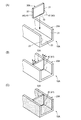
- FIGS. 3A to 3C are perspective views showing a method for manufacturing a ceramic structure according to the first embodiment of the present invention.
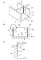
- FIGS. (A) is a perspective view of the ceramic structure of 2nd Embodiment which concerns on this invention, (B) is sectional drawing, (C) is an enlarged view of C part in (B) at the time of 2nd member insertion. It is.
- (A) is a perspective view of the ceramic structure of 3rd Embodiment which concerns on this invention, (B) is a disassembled perspective view of a vertical member and a horizontal member.
- a ceramic structure of the present invention for solving the above problems is made of porous ceramic, and includes a pair of first inner side surfaces facing each other, and a second inner side surface adjacent to each of the first inner side surfaces.
- a pair of first members whose cross-sectional shape is continuous along each of the first inner surface and the second inner surface, and made of porous ceramic and facing each of the first inner surfaces of the first member.
- a second member having a second outer surface adjacent to each of the first outer surfaces and facing the second inner surface of the first member, and as an aggregate, silicon carbide , Cordierite, alumina, mullite, silicon nitride, aluminum titanate, zirconia, and a paste containing an organic binder or an inorganic binder as a binder.
- each first inner surface of the first member and each first outer surface of the second member are respectively The first member and the second member are relatively arranged so as to face each other through the paste, and so that the second inner surface of the first member and the second outer surface of the second member face each other, The first member and the second member are joined through an adhesive layer formed by solidifying the paste.
- the ceramic structure of the present invention has a pair of first inner surfaces facing each other and a second inner surface adjacent to each first inner surface, along the first inner surface and the second inner surface.
- the first member is a porous ceramic having a continuous cross-sectional shape.
- An adhesive layer is provided between each first inner surface and each first outer surface.
- the first member has, for example, a U-shaped cross section, and can be extruded in the longitudinal direction.
- a second member having a shape corresponding to the cross-sectional shape of the first member is attached in a direction intersecting the pushing direction of the first member.
- the second member is fixed inside the first member by the adhesive layer.
- the adhesive layer that joins the first member and the second member includes, as an aggregate, any one of silicon carbide, cordierite, alumina, mullite, silicon nitride, aluminum titanate, and zirconia, It is formed by solidifying a paste containing an organic binder or an inorganic binder. For this reason, after the paste is heated and melted, it is solidified to form an adhesive layer, whereby the second member can be reliably fixed to the inside of the first member. Furthermore, since the adhesive layer is obtained by solidifying the paste, the first member and the second member can be relatively fixed at arbitrary positions.
- the ceramic structure of the present invention has the following aspect.
- (1) The paste is applied and solidified on the second inner surface of the first member or the second outer surface of the second member to form an adhesive layer.
- the second outer surface which is the lower surface of the second member, is fixed to the second inner surface, which is the lower surface of the first member, with the adhesive layer interposed therebetween. Can be fixed to.
- the first member and the second member include any of silicon carbide, cordierite, alumina, mullite, silicon nitride, aluminum titanate, and zirconia.
- the first member and the second member are impregnated with a metal or a semimetal. Therefore, the molten ceramic or metalloid penetrates into the pores of the porous ceramic forming the first member and the second member and solidifies by densifying the porous ceramic, so that the airtightness of the first member and the second member is increased. Can be improved.
- the metal is silicon.
- the manufacturing method of the ceramic structure of the present invention for solving the above-described problem includes a pair of first inner side surfaces facing each other, and second inner side surfaces respectively adjacent to the first inner side surfaces.
- the first member having a continuous cross-sectional shape along each of the first inner surface and the second inner surface is made of porous ceramic, and a pair of first outer surfaces facing away from each other, and the first members
- a second member having a second outer surface adjacent to the outer surface is made of porous ceramic, and as an aggregate, any of silicon carbide, cordierite, alumina, mullite, silicon nitride, aluminum titanate, zirconia is used.
- a paste containing an organic binder or an inorganic binder as a binder is applied to each first inner surface of the first member or each first outer surface of the second member.
- the first inner surface of the first member and the first outer surface of the second member face each other via the paste, and the second inner surface of the first member and the second member.
- the first member and the second member are relatively arranged so as to face the second outer surface of the material, and a solidification step of solidifying the paste is performed.
- a first member having a continuous cross-sectional shape having a pair of first inner surfaces facing each other and a second inner surface adjacent to each first inner surface is provided. Molded with a material that will be a porous ceramic.
- the first member can be produced by extrusion molding.
- a second member having a pair of first outer surfaces facing away from each other and a second outer surface adjacent to each first outer surface is molded from a material that becomes a porous ceramic.
- the second member corresponds to the cross-sectional shape of the first member and can be accommodated inside the first member.
- Each of the first outer surfaces of the second member includes, as an aggregate, any of silicon carbide, cordierite, alumina, mullite, silicon nitride, aluminum titanate, and zirconia, and an organic binder or an inorganic binder as a binder.
- Apply paste containing Thereafter, the first member and the second member are relatively arranged so that each first outer surface and each first inner surface face each other through the paste, and each second outer surface and second inner surface face each other. Then, a solidification step is performed so that at least the solvent of the paste is vaporized. Thereby, the paste is solidified to form an adhesive layer, and two members having different continuous directions can be joined. Furthermore, since the adhesive layer is obtained by solidifying the paste, the first member and the second member can be relatively fixed at arbitrary positions.
- the method for producing a ceramic structure of the present invention is as follows.
- the solidification step is a step of evaporating at least the solvent of the paste and drying it. Thereby, two members having different continuous directions can be joined.
- a heating step is performed in which the first member and the second member are melt-impregnated with a metal or a semimetal. Therefore, the molten ceramic or metalloid penetrates into the pores of the porous ceramic forming the first member and the second member and solidifies by densifying the porous ceramic, so that the airtightness of the first member and the second member is increased. Can be improved.
- the metal is silicon.
- the ceramic structure 10A of the first embodiment includes a first member 20A that is a porous ceramic and a second member 30A.
- the first member 20A and the second member 30A are melt-impregnated with silicon (Si).
- the porous ceramic include silicon carbide (SiC), cordierite, alumina, mullite, silicon nitride, aluminum titanate, and zirconia.
- the first member 20 ⁇ / b> A includes a pair of first inner side surfaces 21 and 22 that face each other, and a second inner side surface 23 that is adjacent to each of the first inner side surfaces 21 and 22.
- the first member 20A can be extruded in the longitudinal direction because, for example, the U-shaped cross section is continuous in the longitudinal direction.
- the longitudinal direction of the first member 20A is referred to as “front” and “rear”, the upper side in FIG. 1A is referred to as “upper”, and the lower side is referred to as “lower”.
- the second member 30A is a shape corresponding to the shape of the internal space 24 formed by the pair of first inner side surfaces 21 and 22 and the second inner side surface 23 of the first member 20A, that is, a rectangular plate-like member. .
- the second member 30A is adjacent to each of the first outer side surfaces 31, 32 facing each of the first inner side surfaces 21, 22 of the first member 20A, and each of the first outer side surfaces 31, 32, and the first member 20A. And a second outer side surface 33 facing the second inner side surface 23.
- the second member 30A is disposed in the internal space 24 of the first member 20A in a direction orthogonal to the longitudinal direction that is the extrusion direction of the first member 20A.
- An adhesive layer 40 is provided between the first inner surface 21 and the first outer surface 31 and between the first inner surface 22 and the first outer surface 32, that is, along the vertical direction. Furthermore, the adhesive layer 40 is also provided between the second inner side surface 23 and the second outer side surface 33, that is, the bottom surface of the internal space 24 of the first member 20A and the bottom surface of the second member 30A. Adhesive layer 40 is formed of paste 41 containing silicon carbide (SiC).
- a method for manufacturing the ceramic structure 10A of the first embodiment will be described.
- a first member 20A having a pair of first inner side surfaces 21 and 22 facing each other and a second inner side surface 23 adjacent to each of the first inner side surfaces 21 and 22 is continuously formed as a porous ceramic. Extrusion is performed with the material to be formed.
- the first member 20A is a member having a U-shaped cross section.
- the second member 30A having a pair of first outer surfaces 31, 32 facing away from each other and a second outer surface 33 adjacent to each of the first outer surfaces 31, 32 is made of a material that becomes a porous ceramic. Mold.
- the second member 30A is a rectangular plate member. Thereafter, the first member 20A and the second member 30A are fired to obtain the porous ceramic first member 20A and the second member 30A.
- a paste 41 for forming an adhesive layer 40 containing SiC is applied to each first outer surface 31, 32 of the second member 30A.
- the paste 41 may be applied in advance to the first inner side surfaces 21 and 22 and the second inner side surface 23 of the first member 20A.
- the first outer surfaces 31 and 32 and the first inner surfaces 21 and 22 face each other through the paste 41, and the second outer surface 33 and the second inner surface.
- the first member 20 ⁇ / b> A and the second member 30 ⁇ / b> A are relatively arranged so that the head 23 faces the head 23.
- the adhesive layer 40 is obtained by performing a solidification step at least to the extent that the solvent of the paste 41 is vaporized.
- the adhesive layer 40 obtained by vaporizing the solvent of the paste 41 at a predetermined ratio maintains its own shape, and can exhibit and maintain an adhesive function with respect to the first member 20A and the second member 30A. Refers to the degree.
- a heating step of melting and impregnating Si into the first member 20A and the second member 30A is performed prior to the heating step in which the first member 20A and the second member 30A are melt-impregnated with Si.
- a solidification step at least to the extent that the solvent of the paste 41 is vaporized is performed prior to the heating step in which the first member 20A and the second member 30A are melt-impregnated with Si.
- the paste 41 easily enters the pores of the first member 20A and the second member 30A.
- the paste 41 is easy to become familiar with the first member 20A and the second member 30A, and the adhesive strength of the adhesive layer 40 to the first member 20A and the adhesive strength of the adhesive layer 40 to the second member 30A are favorably obtained.
- the first member 20A and the second member 30A can be firmly bonded.
- the ceramic structure 10A of the first embodiment has a continuous cross-sectional shape having a pair of first inner side surfaces 21 and 22 facing each other and a second inner side surface 23 adjacent to the first inner side surfaces 21 and 22, respectively.
- the first member 20A is a porous ceramic.
- the second member 30A which is a porous ceramic having An adhesive layer 40 is provided between the first inner side surfaces 21 and 22 and the first outer side surfaces 31 and 32.
- the first member 20A has, for example, a U-shaped cross section, and can be extruded in the longitudinal direction.
- a second member 30A having a shape corresponding to the cross-sectional shape of the first member 20A is attached in a direction crossing the pushing direction of the first member 20A.
- the second member 30A is fixed to the inside of the first member 20A by the adhesive layer 40 in which the paste 41 is solidified.
- the adhesive layer 40 that joins the first member 20A and the second member 30A includes, as an aggregate, any of silicon carbide, cordierite, alumina, mullite, silicon nitride, aluminum titanate, and zirconia.
- a paste 41 containing an organic binder or an inorganic binder As a paste 41 containing an organic binder or an inorganic binder. For this reason, after the paste 41 is heated and melted, the paste 41 is solidified to form the adhesive layer 40, whereby the second member 30A can be reliably fixed to the inside of the first member 20A. Furthermore, since the adhesive layer 40 is obtained by solidifying the paste 41, the first member 20A and the second member 30A can be relatively fixed at arbitrary positions.
- the second outer surface 33 that is the lower surface of the second member 30A is fixed to the second inner surface 23 that is the lower surface of the first member 20A via the adhesive layer 40. Therefore, the second member 30A can be more reliably fixed to the first member 20A.
- the first member 20A and the second member 30A include any of silicon carbide, cordierite, alumina, mullite, silicon nitride, aluminum titanate, and zirconia.
- the first member 20A, the second member 30A, and the adhesive layer 40 have similar physical characteristics and the like, and the physical characteristics such as strength are suitable after bonding.
- various characteristics such as thermal expansion are aligned, which is even more preferable.
- the first member 20A and the second member 30A are melt-impregnated with a metal or a semimetal such as Si. For this reason, the first member 20A and the second member 30A can be densified, and the airtightness can be improved.
- the operation and effect of the method for manufacturing the ceramic structure of the first embodiment will be described.
- the method for manufacturing a ceramic structure of the first embodiment prior to the heating step in which the first member 20A and the second member 30A are melted and impregnated with Si, at least a solidification step in which the solvent of the paste 41 is evaporated. Therefore, the paste 41 easily enters the pores of the first member 20A and the second member 30A that are in the porous state. For this reason, the paste 41 is easy to become familiar with the first member 20A and the second member 30A, and the adhesive strength of the adhesive layer 40 to the first member 20A and the adhesive strength of the adhesive layer 40 to the second member 30A are favorably obtained. As a result, the first member 20A and the second member 30A can be firmly bonded.
- the unevenness 34 is provided on the pair of first outer side surfaces 31 and 32 of the second member 30B.
- the unevenness 34 is desirably provided from the lower end to the upper end of the first outer side surfaces 31 and 32.
- corrugation 34 is not specifically limited, For example, a mountain shape, a waveform, a rectangle, etc. are employable.
- a distance L1 between the tips 341 of the unevenness 34 on the pair of first outer surfaces 31 and 32 is slightly larger than a distance L2 between the pair of first inner surfaces 21 and 22 of the first member 20A.
- the distance L3 between the bottom portions 342 of the unevenness 34 is smaller than the distance L2.
- the tip 341 of the unevenness 34 abuts against the pair of first inner side surfaces 21 and 22. , Inserted while being cut. At this time, the paste 41 is also scraped, but the paste 41 is held in the recesses of the irregularities 34. For this reason, the second member 30B is reliably bonded to the first member 20A by the paste 41.
- the manufacturing method of the ceramic structure 10B can be the same as the manufacturing method of the ceramic structure 10A in the first embodiment described above.
- the interior of the rectangular box-shaped first member 20C is divided into four by the second member 30C.
- the first member 20 ⁇ / b> C is provided with end plates 25 at both front and rear ends of a U-shaped cross-sectional member having a pair of first inner side surfaces 21, 22 and one second inner side surface 23.
- the second member 30 ⁇ / b> C includes a vertical member 35 and a horizontal member 36.
- the vertical member 35 is provided with an incision 351 that opens upward in the upper center of the longitudinal direction.
- the transverse member 36 is provided with a notch 361 that opens downward in the lower center of the longitudinal direction.
- the width of the cut 351 is substantially equal to the thickness of the horizontal member 36, and the length is larger than half of the width (height) of the horizontal member 36.
- the width of the notch 361 is substantially equal to the thickness of the vertical member 35, and the length is larger than half of the width of the vertical member 35. Therefore, the cross-shaped second member 30C is formed by fitting the cut 351 and the cut 361 to each other.
- the manufacturing method of the ceramic structure of 3rd Embodiment is demonstrated.
- a rectangular box-shaped first member 20 ⁇ / b> C whose top is opened is formed. That is, the first member 20A is manufactured in the same manner as the manufacturing method of the first embodiment described above, and the two second members 30A, the vertical member 35, and the horizontal member 36 are manufactured.
- end plates 25 are provided at both ends in the longitudinal direction of the first member 20A and joined with the paste 41 to produce a rectangular box-shaped first member 20C.
- the longitudinal member 35 is disposed along the longitudinal direction at the center in the width direction inside the first member 20 ⁇ / b> C, and is attached between the pair of end plates 25 with the paste 41.
- the cut 361 of the horizontal member 36 is fitted into the cut 351 of the vertical member 35, and the horizontal member 36 is attached. Both ends of the horizontal member 36 and the cut 361 are joined by the paste 41.
- the solidification step and the heating step are performed in the same manner as in the first embodiment.
- the ceramic structure and the method of manufacturing the ceramic structure of the present invention are not limited to the above-described embodiments, and appropriate modifications and improvements can be made.
- This application is based on a Japanese patent application filed on July 28, 2014 (Japanese Patent Application No. 2014-153250), the contents of which are incorporated herein by reference.
- the ceramic structure and the ceramic structure manufacturing method of the present invention can be used in a ceramic structure in which two members having different continuous directions are joined and a method for manufacturing the ceramic structure.
Landscapes
- Chemical & Material Sciences (AREA)
- Engineering & Computer Science (AREA)
- Ceramic Engineering (AREA)
- Materials Engineering (AREA)
- Structural Engineering (AREA)
- Organic Chemistry (AREA)
- Inorganic Chemistry (AREA)
- Ceramic Products (AREA)
- Porous Artificial Stone Or Porous Ceramic Products (AREA)
Abstract
互いに対向する一対の第1内側面(21、22)と、各第1内側面(21、22)に隣り合う第2内側面(23)とを有する断面形状が連続する多孔質セラミックである第1部材(20A)とを有する。各第1内側面(21、22)にそれぞれ向かい合う一対の第1外側面(31、32)と、各第1外側面(31、32)に隣り合うとともに第2内側面(23)に向かい合う第2外側面(33)とを有する多孔質セラミックである第2部材(30A)を有する。各第1内側面(21、22)および各第1外側面(31、32)間には、接着層(40)が設けられている。このため、第1部材(20A)は、長手方向に押し出し成形することができる。第1部材(20A)の内側には、第2部材(30A)が、第1部材(20A)の押し出し方向と交差する方向に取り付けられるので、互いに連続方向が異なる2つの部材を接合することができる。
Description
本発明は、互いに連続方向が異なる2つの部材を接合したセラミック構造体およびセラミック構造体の製造方法に関する。
従来、押し出し成形により形成された部材と、この押し出し方向と直交する方向に形成された部材とを有するセラミック構造体(セラミックス焼結体)を製造するには、二つの部材を接続する方法が提案されている(例えば、特許文献1参照)。
特許文献1に記載のセラミック構造体では、円盤状の基部の上に、円筒形状の筒部を有する。このような最終成形体を形成する際に、まず、最終成形体に近いがラフな形状の2個以上の予備成形体を作製し、各予備成形体を組み合わせ、加圧して焼結する。
特許文献1に記載のセラミック構造体では、円盤状の基部の上に、円筒形状の筒部を有する。このような最終成形体を形成する際に、まず、最終成形体に近いがラフな形状の2個以上の予備成形体を作製し、各予備成形体を組み合わせ、加圧して焼結する。
ところで、例えば一対の板部材がT字状に接続されたような形状を多孔質焼成体により一体成型する場合、一方の板部材における他方の板部材とは反対側の表面に引けが生ずる可能性がある。
このため、多孔質焼成体により別体成型された一対の板部材をT字状に接続する構造が求められている。
このため、多孔質焼成体により別体成型された一対の板部材をT字状に接続する構造が求められている。
本発明では、前記課題を鑑み、互いに連続方向が異なる2つの部材を接合できるセラミック構造体およびセラミック構造体の製造方法を提供することを目的とする。
前記課題を解決するための本発明のセラミック構造体は、多孔質セラミックにより作成され、互いに対向する一対の第1内側面と、前記各第1内側面にそれぞれ隣り合う第2内側面と、を有し、前記各第1内側面および前記第2内側面に沿って断面形状が連続する第1部材と、多孔質セラミックにより作成され、前記第1部材の前記各第1内側面にそれぞれ向かい合う一対の第1外側面と、前記各第1外側面にそれぞれ隣り合うとともに前記第1部材の前記第2内側面に向かい合う第2外側面とを有する第2部材とを備え、骨材として、炭化珪素、コーディエライト、アルミナ、ムライト、窒化珪素、アルミニウムチタネート、ジルコニアの何れかを含み、結合材として、有機バインダまたは無機バインダを含むペーストを、前記第1部材の各前記第1内側面または前記第2部材の前記各第1外側面に塗布した後、前記第1部材の前記各第1内側面と前記第2部材の前記各第1外側面とがそれぞれ前記ペーストを介して向かい合うとともに、前記第1部材の前記第2内側面と前記第2部材の前記第2外側面とが向かい合うように前記第1部材および前記第2部材を相対的に配置させ、前記ペーストを固化させることによって形成される接着層を介して、前記第1部材と前記第2部材とを結合する。
本発明のセラミック構造体は、互いに対向する一対の第1内側面と、各第1内側面にそれぞれ隣り合う第2内側面と、を有し、各第1内側面および第2内側面に沿って断面形状が連続する多孔質セラミックである第1部材を有する。また、各第1内側面にそれぞれ向かい合う一対の第1外側面と、各第1外側面にそれぞれ隣り合うとともに第2内側面に向かい合う第2外側面とを有する多孔質セラミックである第2部材を有する。そして、各第1内側面および各第1外側面間には、接着層が設けられている。
このため、第1部材は例えば断面コ字状を呈しており、長手方向に押し出し成形することができる。第1部材の内側には、第1部材の断面形状に対応した形状の第2部材が、第1部材の押し出し方向と交差する方向に取り付けられる。このとき、第2部材は接着層により第1部材の内側に固定される。
これにより、互いに連続方向が異なる2つの部材を接合することができる。
これにより、互いに連続方向が異なる2つの部材を接合することができる。
また、前記第1部材と前記第2部材とを結合する接着層は、骨材として、炭化珪素、コーディエライト、アルミナ、ムライト、窒化珪素、アルミニウムチタネート、ジルコニアの何れかを含み、結合材として、有機バインダまたは無機バインダを含むペーストを固化させることによって形成される。
このため、ペーストが加熱されて溶融した後に固化して接着層となり、これにより第2部材を第1部材の内側に確実に固定することができる。
さらに、接着層は、ペーストを固化させて得られるため、第1部材および第2部材を相対的に任意位置で固定できる。
このため、ペーストが加熱されて溶融した後に固化して接着層となり、これにより第2部材を第1部材の内側に確実に固定することができる。
さらに、接着層は、ペーストを固化させて得られるため、第1部材および第2部材を相対的に任意位置で固定できる。
さらに、本発明のセラミック構造体は、以下の態様であることが望ましい。
(1)前記第1部材の前記第2内側面または前記第2部材の前記第2外側面にも前記ペーストを塗布して固化させ、接着層を形成する。
このため、第2部材の下面である第2外側面は、接着層を介して第1部材の下面である第2内側面に固定されるので、第2部材を第1部材に対してさらに確実に固定することができる。
(1)前記第1部材の前記第2内側面または前記第2部材の前記第2外側面にも前記ペーストを塗布して固化させ、接着層を形成する。
このため、第2部材の下面である第2外側面は、接着層を介して第1部材の下面である第2内側面に固定されるので、第2部材を第1部材に対してさらに確実に固定することができる。
(2)前記第1部材および前記第2部材は、炭化珪素、コーディエライト、アルミナ、ムライト、窒化珪素、アルミニウムチタネート、ジルコニアの何れかを含む。
(3)前記第1部材および前記第2部材に対して、金属または半金属を溶融含浸させたものである。
このため、第1部材および第2部材を形成する多孔質セラミックの気孔に溶融した金属または半金属が侵入して固化することにより多孔質セラミックを緻密化して、第1部材および第2部材の気密性を向上させることができる。
このため、第1部材および第2部材を形成する多孔質セラミックの気孔に溶融した金属または半金属が侵入して固化することにより多孔質セラミックを緻密化して、第1部材および第2部材の気密性を向上させることができる。
(4)前記金属は、珪素である。
前記課題を解決するための本発明のセラミック構造体の製造方法は、互いに対向する一対の第1内側面と、前記各第1内側面にそれぞれ隣り合う第2内側面と、を有し、前記各第1内側面および前記第2内側面に沿って断面形状が連続する第1部材を多孔質セラミックにより作成するとともに、互いに離れる方向を向く一対の第1外側面と、前記各第1外側面にそれぞれ隣り合う第2外側面とを有する第2部材を多孔質セラミックにより作成し、骨材として、炭化珪素、コーディエライト、アルミナ、ムライト、窒化珪素、アルミニウムチタネート、ジルコニアの何れかを含み、結合材として、有機バインダまたは無機バインダを含むペーストを、前記第1部材の前記各第1内側面または前記第2部材の前記各第1外側面に塗布した後、前記第1部材の前記各第1内側面と前記第2部材の前記各第1外側面とがそれぞれ前記ペーストを介して向かい合うとともに、前記第1部材の前記第2内側面と前記第2部材の前記第2外側面とが向かい合うように前記第1部材および前記第2部材を相対的に配置させ、前記ペーストを固化させる固化工程を行う。
本発明のセラミック構造体の製造方法によれば、まず、互いに対向する一対の第1内側面と、各第1内側面にそれぞれ隣り合う第2内側面と、を有する断面形状が連続する第1部材を多孔質セラミックとなる材料により成型する。第1部材は、押出成形により作製することができる。また、互いに離れる方向を向く一対の第1外側面と、各第1外側面にそれぞれ隣り合う第2外側面とを有する第2部材を多孔質セラミックとなる材料により成型する。
その後、第1部材および第2部材を焼成して、多孔質セラミックの第1部材および第2部材を得る。第2部材は、第1部材の断面形状に対応しており、第1部材の内部に収容可能である。
その後、第1部材および第2部材を焼成して、多孔質セラミックの第1部材および第2部材を得る。第2部材は、第1部材の断面形状に対応しており、第1部材の内部に収容可能である。
そして、第2部材の各第1外側面に骨材として、炭化珪素、コーディエライト、アルミナ、ムライト、窒化珪素、アルミニウムチタネート、ジルコニアの何れかを含み、結合材として、有機バインダまたは無機バインダを含むペーストを塗布する。その後、各第1外側面と各第1内側面とがそれぞれペーストを介して向かい合うとともに、第2外側面と第2内側面とが向かい合うように第1部材および第2部材を相対的に配置し、少なくともペーストの溶媒が気化する程度の固化工程を行う。
これにより、ペーストが固化して接着層となり、互いに連続方向が異なる2つの部材を接合することができる。
さらに、接着層は、ペーストを固化させて得られるため、第1部材および第2部材を相対的に任意位置で固定できる。
これにより、ペーストが固化して接着層となり、互いに連続方向が異なる2つの部材を接合することができる。
さらに、接着層は、ペーストを固化させて得られるため、第1部材および第2部材を相対的に任意位置で固定できる。
さらに、本発明のセラミック構造体の製造方法は、以下の態様であることが望ましい。
(1)前記固化工程は、少なくとも前記ペーストの溶媒を気化させて乾燥させる工程である。
これにより、互いに連続方向が異なる2つの部材を接合することができる。
(1)前記固化工程は、少なくとも前記ペーストの溶媒を気化させて乾燥させる工程である。
これにより、互いに連続方向が異なる2つの部材を接合することができる。
(2)前記固化工程の後、前記第1部材および前記第2部材に金属または半金属を溶融含浸させる加熱工程を行う。
このため、第1部材および第2部材を形成する多孔質セラミックの気孔に溶融した金属または半金属が侵入して固化することにより多孔質セラミックを緻密化して、第1部材および第2部材の気密性を向上させることができる。
このため、第1部材および第2部材を形成する多孔質セラミックの気孔に溶融した金属または半金属が侵入して固化することにより多孔質セラミックを緻密化して、第1部材および第2部材の気密性を向上させることができる。
(3)前記金属は、珪素である。
本発明によれば、第1部材は例えば断面コ字状を呈しており、長手方向に押し出し成形することができる。第1部材の内側には、第1部材の断面形状に対応した形状の第2部材が、第1部材の押し出し方向と交差する方向に取り付けられる。このとき、第2部材は接着層により第1部材の内側に固定されるので、互いに連続方向が異なる2つの部材を接合することができる。
本発明のセラミック構造体およびセラミック構造体の製造方法について説明する。
前記課題を解決するための本発明のセラミック構造体は、多孔質セラミックにより作成され、互いに対向する一対の第1内側面と、前記各第1内側面にそれぞれ隣り合う第2内側面と、を有し、前記各第1内側面および前記第2内側面に沿って断面形状が連続する第1部材と、多孔質セラミックにより作成され、前記第1部材の前記各第1内側面にそれぞれ向かい合う一対の第1外側面と、前記各第1外側面にそれぞれ隣り合うとともに前記第1部材の前記第2内側面に向かい合う第2外側面とを有する第2部材とを備え、骨材として、炭化珪素、コーディエライト、アルミナ、ムライト、窒化珪素、アルミニウムチタネート、ジルコニアの何れかを含み、結合材として、有機バインダまたは無機バインダを含むペーストを、前記第1部材の各前記第1内側面または前記第2部材の前記各第1外側面に塗布した後、前記第1部材の前記各第1内側面と前記第2部材の前記各第1外側面とがそれぞれ前記ペーストを介して向かい合うとともに、前記第1部材の前記第2内側面と前記第2部材の前記第2外側面とが向かい合うように前記第1部材および前記第2部材を相対的に配置させ、前記ペーストを固化させることによって形成される接着層を介して、前記第1部材と前記第2部材とを結合する。
本発明のセラミック構造体は、互いに対向する一対の第1内側面と、各第1内側面にそれぞれ隣り合う第2内側面と、を有し、各第1内側面および第2内側面に沿って断面形状が連続する多孔質セラミックである第1部材を有する。また、各第1内側面にそれぞれ向かい合う一対の第1外側面と、各第1外側面にそれぞれ隣り合うとともに第2内側面に向かい合う第2外側面とを有する多孔質セラミックである第2部材を有する。そして、各第1内側面および各第1外側面間には、接着層が設けられている。
このため、第1部材は例えば断面コ字状を呈しており、長手方向に押し出し成形することができる。第1部材の内側には、第1部材の断面形状に対応した形状の第2部材が、第1部材の押し出し方向と交差する方向に取り付けられる。このとき、第2部材は接着層により第1部材の内側に固定される。
これにより、互いに連続方向が異なる2つの部材を接合することができる。
これにより、互いに連続方向が異なる2つの部材を接合することができる。
また、前記第1部材と前記第2部材とを結合する接着層は、骨材として、炭化珪素、コーディエライト、アルミナ、ムライト、窒化珪素、アルミニウムチタネート、ジルコニアの何れかを含み、結合材として、有機バインダまたは無機バインダを含むペーストを固化させることによって形成される。
このため、ペーストが加熱されて溶融した後に固化して接着層となり、これにより第2部材を第1部材の内側に確実に固定することができる。
さらに、接着層は、ペーストを固化させて得られるため、第1部材および第2部材を相対的に任意位置で固定できる。
このため、ペーストが加熱されて溶融した後に固化して接着層となり、これにより第2部材を第1部材の内側に確実に固定することができる。
さらに、接着層は、ペーストを固化させて得られるため、第1部材および第2部材を相対的に任意位置で固定できる。
さらに、本発明のセラミック構造体は、以下の態様であることが望ましい。
(1)前記第1部材の前記第2内側面または前記第2部材の前記第2外側面にも前記ペーストを塗布して固化させ、接着層を形成する。
このため、第2部材の下面である第2外側面は、接着層を介して第1部材の下面である第2内側面に固定されるので、第2部材を第1部材に対してさらに確実に固定することができる。
(1)前記第1部材の前記第2内側面または前記第2部材の前記第2外側面にも前記ペーストを塗布して固化させ、接着層を形成する。
このため、第2部材の下面である第2外側面は、接着層を介して第1部材の下面である第2内側面に固定されるので、第2部材を第1部材に対してさらに確実に固定することができる。
(2)前記第1部材および前記第2部材は、炭化珪素、コーディエライト、アルミナ、ムライト、窒化珪素、アルミニウムチタネート、ジルコニアの何れかを含む。
(3)前記第1部材および前記第2部材に対して、金属または半金属を溶融含浸させたものである。
このため、第1部材および第2部材を形成する多孔質セラミックの気孔に溶融した金属または半金属が侵入して固化することにより多孔質セラミックを緻密化して、第1部材および第2部材の気密性を向上させることができる。
このため、第1部材および第2部材を形成する多孔質セラミックの気孔に溶融した金属または半金属が侵入して固化することにより多孔質セラミックを緻密化して、第1部材および第2部材の気密性を向上させることができる。
(4)前記金属は、珪素である。
また、前記課題を解決するための本発明のセラミック構造体の製造方法は、互いに対向する一対の第1内側面と、前記各第1内側面にそれぞれ隣り合う第2内側面と、を有し、前記各第1内側面および前記第2内側面に沿って断面形状が連続する第1部材を多孔質セラミックにより作成するとともに、互いに離れる方向を向く一対の第1外側面と、前記各第1外側面にそれぞれ隣り合う第2外側面とを有する第2部材を多孔質セラミックにより作成し、骨材として、炭化珪素、コーディエライト、アルミナ、ムライト、窒化珪素、アルミニウムチタネート、ジルコニアの何れかを含み、結合材として、有機バインダまたは無機バインダを含むペーストを、前記第1部材の前記各第1内側面または前記第2部材の前記各第1外側面に塗布した後、前記第1部材の前記各第1内側面と前記第2部材の前記各第1外側面とがそれぞれ前記ペーストを介して向かい合うとともに、前記第1部材の前記第2内側面と前記第2部材の前記第2外側面とが向かい合うように前記第1部材および前記第2部材を相対的に配置させ、前記ペーストを固化させる固化工程を行う。
本発明のセラミック構造体の製造方法は、まず、互いに対向する一対の第1内側面と、各第1内側面にそれぞれ隣り合う第2内側面と、を有する断面形状が連続する第1部材を多孔質セラミックとなる材料により成型する。第1部材は、押出成形により作製することができる。また、互いに離れる方向を向く一対の第1外側面と、各第1外側面にそれぞれ隣り合う第2外側面とを有する第2部材を多孔質セラミックとなる材料により成型する。第2部材は、第1部材の断面形状に対応しており、第1部材の内部に収容可能である。
そして、第2部材の各第1外側面に骨材として、炭化珪素、コーディエライト、アルミナ、ムライト、窒化珪素、アルミニウムチタネート、ジルコニアの何れかを含み、結合材として、有機バインダまたは無機バインダを含むペーストを塗布する。その後、各第1外側面と各第1内側面とがそれぞれペーストを介して向かい合うとともに、第2外側面と第2内側面とが向かい合うように第1部材および第2部材を相対的に配置し、少なくともペーストの溶媒が気化する程度の固化工程を行う。
これにより、ペーストが固化して接着層となり、互いに連続方向が異なる2つの部材を接合することができる。
さらに、接着層は、ペーストを固化させて得られるため、第1部材および第2部材を相対的に任意位置で固定できる。
これにより、ペーストが固化して接着層となり、互いに連続方向が異なる2つの部材を接合することができる。
さらに、接着層は、ペーストを固化させて得られるため、第1部材および第2部材を相対的に任意位置で固定できる。
さらに、本発明のセラミック構造体の製造方法は、以下の態様であることが望ましい。
(1)前記固化工程は、少なくとも前記ペーストの溶媒を気化させて乾燥させる工程である。
これにより、互いに連続方向が異なる2つの部材を接合することができる。
(1)前記固化工程は、少なくとも前記ペーストの溶媒を気化させて乾燥させる工程である。
これにより、互いに連続方向が異なる2つの部材を接合することができる。
(2)前記固化工程の後、前記第1部材および前記第2部材に金属または半金属を溶融含浸させる加熱工程を行う。
このため、第1部材および第2部材を形成する多孔質セラミックの気孔に溶融した金属または半金属が侵入して固化することにより多孔質セラミックを緻密化して、第1部材および第2部材の気密性を向上させることができる。
このため、第1部材および第2部材を形成する多孔質セラミックの気孔に溶融した金属または半金属が侵入して固化することにより多孔質セラミックを緻密化して、第1部材および第2部材の気密性を向上させることができる。
(3)前記金属は、珪素である。
(第1実施形態)
第1実施形態のセラミック構造体およびセラミック構造体の製造方法について説明する。
第1実施形態のセラミック構造体およびセラミック構造体の製造方法について説明する。
図1(A)および図1(B)に示すように、第1実施形態のセラミック構造体10Aは、多孔質セラミックである第1部材20Aと、第2部材30Aとを有する。第1部材20Aおよび第2部材30Aは、珪素(Si)を溶融含浸させたものである。多孔質セラミックとしては、例えば、炭化珪素(SiC)、コーディエライト、アルミナ、ムライト、窒化珪素、アルミニウムチタネート、ジルコニア等を挙げることができる。
第1部材20Aは、互いに対向する一対の第1内側面21、22と、各第1内側面21、22にそれぞれ隣り合う第2内側面23と、を有する。従って、第1部材20Aは、例えばコ字状の断面が長手方向に連続するため、長手方向に押出成形することができる。
なお、以下の説明においては、第1部材20Aの長手方向を「前」および「後」とし、図1(A)における上側を「上」、下側を「下」と云うこととする。
第1部材20Aは、互いに対向する一対の第1内側面21、22と、各第1内側面21、22にそれぞれ隣り合う第2内側面23と、を有する。従って、第1部材20Aは、例えばコ字状の断面が長手方向に連続するため、長手方向に押出成形することができる。
なお、以下の説明においては、第1部材20Aの長手方向を「前」および「後」とし、図1(A)における上側を「上」、下側を「下」と云うこととする。
第2部材30Aは、第1部材20Aの一対の第1内側面21、22と第2内側面23とにより形成される内部空間24の形状に対応した形状、すなわち矩形状の板状部材である。第2部材30Aは、第1部材20Aの各第1内側面21、22にそれぞれ向かい合う一対の第1外側面31、32と、各第1外側面31、32にそれぞれ隣り合うとともに第1部材20Aの第2内側面23に向かい合う第2外側面33とを有する。第2部材30Aは、第1部材20Aの内部空間24内に、第1部材20Aの押出方向である長手方向に直交する方向に配置される。
そして、第1内側面21と第1外側面31との間、および第1内側面22と第1外側面32との間、すなわち上下方向に沿って、接着層40が設けられている。
さらに、第2内側面23と第2外側面33との間、すなわち、第1部材20Aの内部空間24の底面および第2部材30Aの底面にも接着層40が設けられている。
接着層40は、炭化珪素(SiC)を含むペースト41により成形される。
さらに、第2内側面23と第2外側面33との間、すなわち、第1部材20Aの内部空間24の底面および第2部材30Aの底面にも接着層40が設けられている。
接着層40は、炭化珪素(SiC)を含むペースト41により成形される。
次に、第1実施形態のセラミック構造体10Aの製造方法について説明する。
まず、互いに対向する一対の第1内側面21、22と、各第1内側面21、22にそれぞれ隣り合う第2内側面23とを有する断面形状が連続する第1部材20Aを多孔質セラミックとなる材料により押出成形する。第1部材20Aは、断面コ字状の部材である。
また、互いに離れる方向を向く一対の第1外側面31、32と、各第1外側面31、32にそれぞれ隣り合う第2外側面33とを有する第2部材30Aを多孔質セラミックとなる材料により成型する。第2部材30Aは、矩形板状の部材である。
その後、第1部材20Aおよび第2部材30Aを焼成して、多孔質セラミックの第1部材20Aおよび第2部材30Aを得る。
まず、互いに対向する一対の第1内側面21、22と、各第1内側面21、22にそれぞれ隣り合う第2内側面23とを有する断面形状が連続する第1部材20Aを多孔質セラミックとなる材料により押出成形する。第1部材20Aは、断面コ字状の部材である。
また、互いに離れる方向を向く一対の第1外側面31、32と、各第1外側面31、32にそれぞれ隣り合う第2外側面33とを有する第2部材30Aを多孔質セラミックとなる材料により成型する。第2部材30Aは、矩形板状の部材である。
その後、第1部材20Aおよび第2部材30Aを焼成して、多孔質セラミックの第1部材20Aおよび第2部材30Aを得る。
そして、図2(A)に示すように、第2部材30Aの各第1外側面31、32にSiCを含む接着層40を形成するペースト41を塗布する。このとき、第2外側面33にもペースト41を塗布するのが望ましい。
なお、ペースト41は、あらかじめ第1部材20Aの各第1内側面21、22および第2内側面23に塗布しておいてもよい。
その後、図2(B)に示すように、各第1外側面31、32と各第1内側面21、22とがそれぞれペースト41を介して向かい合うとともに、第2外側面33と第2内側面23とが向かい合うように第1部材20Aおよび第2部材30Aを相対的に配置する。この状態で、少なくともペースト41の溶媒が気化する程度の固化工程を行うことにより接着層40を得る。
この固化工程は、ペースト41の溶媒が所定割合で気化して得られた接着層40が自己形状を維持し、かつ、第1部材20Aおよび第2部材30Aに対して接着機能を発揮、維持できる程度のものを指す。
なお、ペースト41は、あらかじめ第1部材20Aの各第1内側面21、22および第2内側面23に塗布しておいてもよい。
その後、図2(B)に示すように、各第1外側面31、32と各第1内側面21、22とがそれぞれペースト41を介して向かい合うとともに、第2外側面33と第2内側面23とが向かい合うように第1部材20Aおよび第2部材30Aを相対的に配置する。この状態で、少なくともペースト41の溶媒が気化する程度の固化工程を行うことにより接着層40を得る。
この固化工程は、ペースト41の溶媒が所定割合で気化して得られた接着層40が自己形状を維持し、かつ、第1部材20Aおよび第2部材30Aに対して接着機能を発揮、維持できる程度のものを指す。
最後に、図2(C)に示すように、固化工程の後、第1部材20Aおよび第2部材30AにSiを溶融含浸させる加熱工程を行う。
このように、第1部材20Aおよび第2部材30Aに対してSiを溶融含浸させる加熱工程に先立って、少なくともペースト41の溶媒が気化する程度の固化工程を行うため、多孔質の状態である第1部材20Aおよび第2部材30Aの気孔にペースト41が容易に浸入する。このため、第1部材20Aおよび第2部材30Aに対してペースト41が馴染み易く、第1部材20Aに対する接着層40の接着強度および第2部材30Aに対する接着層40の接着強度が良好に得られ、結果的に第1部材20Aおよび第2部材30Aを強固に接着できる。
このように、第1部材20Aおよび第2部材30Aに対してSiを溶融含浸させる加熱工程に先立って、少なくともペースト41の溶媒が気化する程度の固化工程を行うため、多孔質の状態である第1部材20Aおよび第2部材30Aの気孔にペースト41が容易に浸入する。このため、第1部材20Aおよび第2部材30Aに対してペースト41が馴染み易く、第1部材20Aに対する接着層40の接着強度および第2部材30Aに対する接着層40の接着強度が良好に得られ、結果的に第1部材20Aおよび第2部材30Aを強固に接着できる。
次に、第1実施形態のセラミック構造体10Aの作用、効果について説明する。
第1実施形態のセラミック構造体10Aは、互いに対向する一対の第1内側面21、22と、各第1内側面21、22にそれぞれ隣り合う第2内側面23と、を有する断面形状が連続する多孔質セラミックである第1部材20Aを有する。また、各第1内側面21、22にそれぞれ向かい合う一対の第1外側面31、32と、各第1外側面31、32にそれぞれ隣り合うとともに第2内側面23に向かい合う第2外側面33とを有する多孔質セラミックである第2部材30Aを有する。そして、各第1内側面21、22および各第1外側面31、32の間には、接着層40が設けられている。
第1実施形態のセラミック構造体10Aは、互いに対向する一対の第1内側面21、22と、各第1内側面21、22にそれぞれ隣り合う第2内側面23と、を有する断面形状が連続する多孔質セラミックである第1部材20Aを有する。また、各第1内側面21、22にそれぞれ向かい合う一対の第1外側面31、32と、各第1外側面31、32にそれぞれ隣り合うとともに第2内側面23に向かい合う第2外側面33とを有する多孔質セラミックである第2部材30Aを有する。そして、各第1内側面21、22および各第1外側面31、32の間には、接着層40が設けられている。
このため、第1部材20Aは例えば断面コ字状を呈しており、長手方向に押し出し成形することができる。第1部材20Aの内側には、第1部材20Aの断面形状に対応した形状の第2部材30Aが、第1部材20Aの押し出し方向と交差する方向に取り付けられる。このとき、第2部材30Aはペースト41が固化した接着層40により第1部材20Aの内側に固定される。
これにより、互いに連続方向が異なる2つの部材(第1部材20A、第2部材30A)を接合することができる。
これにより、互いに連続方向が異なる2つの部材(第1部材20A、第2部材30A)を接合することができる。
また、第1部材20Aと第2部材30Aとを結合する接着層40は、骨材として、炭化珪素、コーディエライト、アルミナ、ムライト、窒化珪素、アルミニウムチタネート、ジルコニアの何れかを含み、結合材として、有機バインダまたは無機バインダを含むペースト41によって形成される。
このため、ペースト41が加熱されて溶融した後に固化して接着層40となり、これにより第2部材30Aを第1部材20Aの内側に確実に固定することができる。
さらに、接着層40は、ペースト41を固化させて得られるため、第1部材20Aおよび第2部材30Aを相対的に任意位置で固定できる。
このため、ペースト41が加熱されて溶融した後に固化して接着層40となり、これにより第2部材30Aを第1部材20Aの内側に確実に固定することができる。
さらに、接着層40は、ペースト41を固化させて得られるため、第1部材20Aおよび第2部材30Aを相対的に任意位置で固定できる。
第1実施形態のセラミック構造体10Aによれば、第2部材30Aの下面である第2外側面33は、接着層40を介して第1部材20Aの下面である第2内側面23に固定されるので、第2部材30Aを第1部材20Aに対してさらに確実に固定することができる。
また、第1実施形態のセラミック構造体10Aによれば、第1部材20Aおよび第2部材30Aは、炭化珪素、コーディエライト、アルミナ、ムライト、窒化珪素、アルミニウムチタネート、ジルコニアの何れかを含むため、第1部材20Aと第2部材30Aと接着層40とは互いに物理特性などが似ており、接着後も強度などの物理特性が好適である。
特に第1部材20Aと第2部材30Aと接着層40との素材を揃えた場合には、熱膨張などの諸特性が揃い、より一層好適である。
特に第1部材20Aと第2部材30Aと接着層40との素材を揃えた場合には、熱膨張などの諸特性が揃い、より一層好適である。
第1実施形態のセラミック構造体10Aによれば、第1部材20Aおよび第2部材30Aは、金属または半金属、例えばSiを溶融含浸させたものである。このため、第1部材20Aおよび第2部材30Aを緻密化することができ、気密性を向上させることができる。
次に、第1実施形態のセラミック構造体の製造方法の作用、効果について説明する。
第1実施形態のセラミック構造体の製造方法によれば、第1部材20Aおよび第2部材30Aに対してSiを溶融含浸させる加熱工程に先立って、少なくともペースト41の溶媒が気化する程度の固化工程を行うため、多孔質の状態である第1部材20Aおよび第2部材30Aの気孔にペースト41が容易に浸入する。このため、第1部材20Aおよび第2部材30Aに対してペースト41が馴染み易く、第1部材20Aに対する接着層40の接着強度および第2部材30Aに対する接着層40の接着強度が良好に得られ、結果的に第1部材20Aおよび第2部材30Aを強固に接着できる。
第1実施形態のセラミック構造体の製造方法によれば、第1部材20Aおよび第2部材30Aに対してSiを溶融含浸させる加熱工程に先立って、少なくともペースト41の溶媒が気化する程度の固化工程を行うため、多孔質の状態である第1部材20Aおよび第2部材30Aの気孔にペースト41が容易に浸入する。このため、第1部材20Aおよび第2部材30Aに対してペースト41が馴染み易く、第1部材20Aに対する接着層40の接着強度および第2部材30Aに対する接着層40の接着強度が良好に得られ、結果的に第1部材20Aおよび第2部材30Aを強固に接着できる。
(第2実施形態)
次に、第2実施形態のセラミック構造体10Bについて説明する。
なお、前述した第1実施形態のセラミック構造体10Aおよびセラミック構造体の製造方法と共通する部位には同じ符号を付して、重複する説明を省略することとする。
次に、第2実施形態のセラミック構造体10Bについて説明する。
なお、前述した第1実施形態のセラミック構造体10Aおよびセラミック構造体の製造方法と共通する部位には同じ符号を付して、重複する説明を省略することとする。
図3(A)ないし図3(C)に示すように、第2実施形態のセラミック構造体10Bでは、第2部材30Bの一対の第1外側面31、32に、凹凸34を設けた。凹凸34は、第1外側面31、32の下端から上端まで設けるのが望ましい。凹凸34の形状は特に限定するものではないが、例えば、山形、波形、矩形等が採用できる。
一対の第1外側面31、32における凹凸34の先端341(図3(C)参照)間の距離L1は、第1部材20Aの一対の第1内側面21、22間の距離L2よりも若干大きいが、凹凸34の底部342間の距離L3は、距離L2よりも小さい。
一対の第1外側面31、32における凹凸34の先端341(図3(C)参照)間の距離L1は、第1部材20Aの一対の第1内側面21、22間の距離L2よりも若干大きいが、凹凸34の底部342間の距離L3は、距離L2よりも小さい。
従って、図3(C)に示すように、第2部材30Bを第1部材20Aの内部空間24に嵌める際には、凹凸34の先端341が、一対の第1内側面21、22に当接し、削られながら挿入される。この際に、ペースト41も削られるが、凹凸34の凹部にはペースト41が保持される。
このため、第2部材30Bは、ペースト41によって確実に第1部材20Aに接合される。
なお、セラミック構造体10Bの製造方法は、前述した第1実施形態におけるセラミック構造体10Aの製造方法と同様にすることができる。
このため、第2部材30Bは、ペースト41によって確実に第1部材20Aに接合される。
なお、セラミック構造体10Bの製造方法は、前述した第1実施形態におけるセラミック構造体10Aの製造方法と同様にすることができる。
(第3実施形態)
次に、第3実施形態のセラミック構造体10Cについて説明する。
なお、前述した第1実施形態のセラミック構造体10Aおよびセラミック構造体の製造方法、第2実施形態のセラミック構造体10Bと共通する部位には同じ符号を付して、重複する説明を省略することとする。
次に、第3実施形態のセラミック構造体10Cについて説明する。
なお、前述した第1実施形態のセラミック構造体10Aおよびセラミック構造体の製造方法、第2実施形態のセラミック構造体10Bと共通する部位には同じ符号を付して、重複する説明を省略することとする。
図4(A)および図4(B)に示すように、第3実施形態のセラミック構造体10Cでは、矩形箱状の第1部材20Cの内部を第2部材30Cにより4分割している。
第1部材20Cは、一対の第1内側面21、22と1個の第2内側面23を有する断面コ字状部材の前後両端に端板25を設けたものである。
また、第2部材30Cは、縦部材35と横部材36によって構成される。縦部材35には、長手方向中央の上部に、上側に開口する切込み351が設けられている。横部材36には、長手方向中央の下部に、下側に開口する切込み361が設けられている。切込み351の幅は横部材36の厚さと略等しく、長さは横部材36の幅(高さ)の半分よりも大きい。また、切込み361の幅は縦部材35の厚さと略等しく、長さは縦部材35の幅の半分よりも大きい。
従って、切込み351と切込み361とを相互に嵌入することにより、十字形状の第2部材30Cを形成する。
第1部材20Cは、一対の第1内側面21、22と1個の第2内側面23を有する断面コ字状部材の前後両端に端板25を設けたものである。
また、第2部材30Cは、縦部材35と横部材36によって構成される。縦部材35には、長手方向中央の上部に、上側に開口する切込み351が設けられている。横部材36には、長手方向中央の下部に、下側に開口する切込み361が設けられている。切込み351の幅は横部材36の厚さと略等しく、長さは横部材36の幅(高さ)の半分よりも大きい。また、切込み361の幅は縦部材35の厚さと略等しく、長さは縦部材35の幅の半分よりも大きい。
従って、切込み351と切込み361とを相互に嵌入することにより、十字形状の第2部材30Cを形成する。
次に、第3実施形態のセラミック構造体の製造方法について説明する。
第3実施形態のセラミック構造体の製造方法においては、まず、上方が開口した矩形箱状の第1部材20Cを形成する。すなわち、前述した第1実施形態の製造方法と同様にして第1部材20Aを作製するとともに、2個の第2部材30A、縦部材35および横部材36を作製する。
第3実施形態のセラミック構造体の製造方法においては、まず、上方が開口した矩形箱状の第1部材20Cを形成する。すなわち、前述した第1実施形態の製造方法と同様にして第1部材20Aを作製するとともに、2個の第2部材30A、縦部材35および横部材36を作製する。
そして、第1実施形態と同様にして、第1部材20Aの長手方向両端にそれぞれ端板25を設けてペースト41により接合して、矩形箱状の第1部材20Cを作製する。
次に、縦部材35を、第1部材20Cの内部において幅方向中央に長手方向に沿って配置し、ペースト41によって一対の端板25間に取り付ける。その後、横部材36の切込み361を縦部材35の切込み351に嵌入させて、横部材36を取り付ける。横部材36の両端および切込み361は、ペースト41によって接合されている。また、縦部材35および横部材36の下面にもペースト41を塗布するのが望ましい。
以後、第1実施形態と同様にして、固化工程および加熱工程を行う。
次に、縦部材35を、第1部材20Cの内部において幅方向中央に長手方向に沿って配置し、ペースト41によって一対の端板25間に取り付ける。その後、横部材36の切込み361を縦部材35の切込み351に嵌入させて、横部材36を取り付ける。横部材36の両端および切込み361は、ペースト41によって接合されている。また、縦部材35および横部材36の下面にもペースト41を塗布するのが望ましい。
以後、第1実施形態と同様にして、固化工程および加熱工程を行う。
このようにしても、前述した第1実施形態および第2実施形態と同様に、互いに連続方向が異なる複数の部材を接合することができる。
本発明のセラミック構造体およびセラミック構造体の製造方法は、前述した各実施形態に限定されるものでなく、適宜な変形、改良等が可能である。
本出願は、2014年7月28日出願の日本国特許出願(特願2014-153250)に基づくものであり、それらの内容はここに参照として取り込まれる。
本出願は、2014年7月28日出願の日本国特許出願(特願2014-153250)に基づくものであり、それらの内容はここに参照として取り込まれる。
本発明のセラミック構造体およびセラミック構造体の製造方法は、互いに連続方向が異なる2つの部材を接合したセラミック構造体およびセラミック構造体の製造方法に用いることができる。
10A、10B、10C セラミック構造体
20A、20C 第1部材
21、22 第1内側面
23 第2内側面
30A、30B、30C 第2部材
31、32 第1外側面
33 第2外側面
40 接着層
41 ペースト
20A、20C 第1部材
21、22 第1内側面
23 第2内側面
30A、30B、30C 第2部材
31、32 第1外側面
33 第2外側面
40 接着層
41 ペースト
Claims (9)
- 多孔質セラミックにより作成され、互いに対向する一対の第1内側面と、前記各第1内側面にそれぞれ隣り合う第2内側面と、を有し、前記各第1内側面および前記第2内側面に沿って断面形状が連続する第1部材と、
多孔質セラミックにより作成され、前記第1部材の前記各第1内側面にそれぞれ向かい合う一対の第1外側面と、前記各第1外側面にそれぞれ隣り合うとともに前記第1部材の前記第2内側面に向かい合う第2外側面とを有する第2部材とを備え、
骨材として、炭化珪素、コーディエライト、アルミナ、ムライト、窒化珪素、アルミニウムチタネート、ジルコニアの何れかを含み、結合材として、有機バインダまたは無機バインダを含むペーストを、前記第1部材の各前記第1内側面または前記第2部材の前記各第1外側面に塗布した後、前記第1部材の前記各第1内側面と前記第2部材の前記各第1外側面とがそれぞれ前記ペーストを介して向かい合うとともに、前記第1部材の前記第2内側面と前記第2部材の前記第2外側面とが向かい合うように前記第1部材および前記第2部材を相対的に配置させ、前記ペーストを固化させることによって形成される接着層を介して、前記第1部材と前記第2部材とを結合することを特徴とするセラミック構造体。 - 前記第1部材の前記第2内側面または前記第2部材の前記第2外側面にも前記ペーストを塗布して固化させ、接着層を形成することを特徴とする請求項1に記載のセラミック構造体。
- 前記第1部材および前記第2部材は、炭化珪素、コーディエライト、アルミナ、ムライト、窒化珪素、アルミニウムチタネート、ジルコニアの何れかを含むことを特徴とする請求項1または請求項2に記載のセラミック構造体。
- 前記第1部材および前記第2部材に対して、金属または半金属を溶融含浸させたことを特徴とする請求項1ないし請求項3のうちのいずれか1項に記載のセラミック構造体。
- 前記金属は、珪素であることを特徴とする請求項4に記載のセラミック構造体。
- 互いに対向する一対の第1内側面と、前記各第1内側面にそれぞれ隣り合う第2内側面と、を有し、前記各第1内側面および前記第2内側面に沿って断面形状が連続する第1部材を多孔質セラミックにより作成するとともに、
互いに離れる方向を向く一対の第1外側面と、前記各第1外側面にそれぞれ隣り合う第2外側面とを有する第2部材を多孔質セラミックにより作成し、
骨材として、炭化珪素、コーディエライト、アルミナ、ムライト、窒化珪素、アルミニウムチタネート、ジルコニアの何れかを含み、結合材として、有機バインダまたは無機バインダを含むペーストを、前記第1部材の前記各第1内側面または前記第2部材の前記各第1外側面に塗布した後、
前記第1部材の前記各第1内側面と前記第2部材の前記各第1外側面とがそれぞれ前記ペーストを介して向かい合うとともに、前記第1部材の前記第2内側面と前記第2部材の前記第2外側面とが向かい合うように前記第1部材および前記第2部材を相対的に配置させ、
前記ペーストを固化させる固化工程を行うことを特徴とするセラミック構造体の製造方法。 - 前記固化工程は、少なくとも前記ペーストの溶媒を気化させて乾燥させる工程であることを特徴とする請求項6に記載のセラミック構造体の製造方法。
- 前記固化工程の後、前記第1部材および前記第2部材に金属または半金属を溶融含浸させる加熱工程を行うことを特徴とする請求項6または請求項7に記載のセラミック構造体の製造方法。
- 前記金属は、珪素であることを特徴とする請求項8に記載のセラミック構造体の製造方法。
Applications Claiming Priority (2)
| Application Number | Priority Date | Filing Date | Title |
|---|---|---|---|
| JP2014153250A JP2016030705A (ja) | 2014-07-28 | 2014-07-28 | セラミック構造体およびセラミック構造体の製造方法 |
| JP2014-153250 | 2014-07-28 |
Publications (1)
| Publication Number | Publication Date |
|---|---|
| WO2016017626A1 true WO2016017626A1 (ja) | 2016-02-04 |
Family
ID=55217526
Family Applications (1)
| Application Number | Title | Priority Date | Filing Date |
|---|---|---|---|
| PCT/JP2015/071350 Ceased WO2016017626A1 (ja) | 2014-07-28 | 2015-07-28 | セラミック構造体およびセラミック構造体の製造方法 |
Country Status (2)
| Country | Link |
|---|---|
| JP (1) | JP2016030705A (ja) |
| WO (1) | WO2016017626A1 (ja) |
Citations (5)
| Publication number | Priority date | Publication date | Assignee | Title |
|---|---|---|---|---|
| JP2002104885A (ja) * | 2000-09-26 | 2002-04-10 | Toshiba Ceramics Co Ltd | 炭化珪素部材の接合体およびその接合方法 |
| JP2002124364A (ja) * | 2000-10-17 | 2002-04-26 | Bridgestone Corp | ヒータ及び半導体製造装置 |
| JP2008137830A (ja) * | 2006-11-30 | 2008-06-19 | Toshiba Corp | セラミックス複合部材とその製造方法 |
| JP2009051684A (ja) * | 2007-08-24 | 2009-03-12 | Bridgestone Corp | 炭化ケイ素構造体及び炭化ケイ素構造体の製造方法 |
| JP2009126724A (ja) * | 2007-11-20 | 2009-06-11 | Bridgestone Corp | 炭化ケイ素接合構造用部材及び炭化ケイ素接合構造用部材の接合方法 |
-
2014
- 2014-07-28 JP JP2014153250A patent/JP2016030705A/ja active Pending
-
2015
- 2015-07-28 WO PCT/JP2015/071350 patent/WO2016017626A1/ja not_active Ceased
Patent Citations (5)
| Publication number | Priority date | Publication date | Assignee | Title |
|---|---|---|---|---|
| JP2002104885A (ja) * | 2000-09-26 | 2002-04-10 | Toshiba Ceramics Co Ltd | 炭化珪素部材の接合体およびその接合方法 |
| JP2002124364A (ja) * | 2000-10-17 | 2002-04-26 | Bridgestone Corp | ヒータ及び半導体製造装置 |
| JP2008137830A (ja) * | 2006-11-30 | 2008-06-19 | Toshiba Corp | セラミックス複合部材とその製造方法 |
| JP2009051684A (ja) * | 2007-08-24 | 2009-03-12 | Bridgestone Corp | 炭化ケイ素構造体及び炭化ケイ素構造体の製造方法 |
| JP2009126724A (ja) * | 2007-11-20 | 2009-06-11 | Bridgestone Corp | 炭化ケイ素接合構造用部材及び炭化ケイ素接合構造用部材の接合方法 |
Also Published As
| Publication number | Publication date |
|---|---|
| JP2016030705A (ja) | 2016-03-07 |
Similar Documents
| Publication | Publication Date | Title |
|---|---|---|
| JP6284114B2 (ja) | セラミック部材およびその製造方法 | |
| JP2017012908A5 (ja) | ||
| CN104903031B (zh) | 多孔铝烧结体 | |
| KR102467165B1 (ko) | 구성요소를 첨가식으로 제조하는 방법 및 첨가식으로 제조된 구성요소 | |
| US6494979B1 (en) | Bonding of thermal tile insulation | |
| TW201808588A (zh) | 接合方法 | |
| US20160272548A1 (en) | Method for the Production of Shaped Articles from Reaction-bonded, Silicon-infiltrated Silicon Carbide and/or Boron Carbide and Thus Produced Shaped Body | |
| JPS6158634B2 (ja) | ||
| WO2018029997A1 (ja) | 断熱シートおよびその製造方法 | |
| CN104994975A (zh) | 烧结用铝原料、烧结用铝原料的制造方法以及多孔铝烧结体的制造方法 | |
| JP2017538293A5 (ja) | ||
| US20140352870A1 (en) | Method of manufacturing honeycomb structured body | |
| JP2016030705A (ja) | セラミック構造体およびセラミック構造体の製造方法 | |
| DE59907061D1 (de) | Keramische flachmembran und verfahren zu ihrer herstellung | |
| JP5379492B2 (ja) | 接合体の製造方法 | |
| JP2015526170A5 (ja) | ||
| CN1758953A (zh) | 多层陶瓷复合材料 | |
| JP2002219317A (ja) | セラミック構造体の製造方法 | |
| JP2019158201A (ja) | 焼成治具 | |
| JP5863447B2 (ja) | SiC/Si複合材料体の製造方法及びSiC/Si複合材料体 | |
| JP2019171441A (ja) | ベースメタル一体型オープンポーラスメタル及びその製造方法 | |
| JP2014525523A (ja) | 断熱目的の構造要素 | |
| KR20130077490A (ko) | 소결체 제조 장치 | |
| WO2018100897A1 (ja) | 断熱シートおよびその製造方法 | |
| US20140158457A1 (en) | Coulomb frictional damping coated product |
Legal Events
| Date | Code | Title | Description |
|---|---|---|---|
| 121 | Ep: the epo has been informed by wipo that ep was designated in this application |
Ref document number: 15827985 Country of ref document: EP Kind code of ref document: A1 |
|
| NENP | Non-entry into the national phase |
Ref country code: DE |
|
| 122 | Ep: pct application non-entry in european phase |
Ref document number: 15827985 Country of ref document: EP Kind code of ref document: A1 |