WO2016017202A1 - Sonde d'observation de forme d'insertion d'endoscope - Google Patents
Sonde d'observation de forme d'insertion d'endoscope Download PDFInfo
- Publication number
- WO2016017202A1 WO2016017202A1 PCT/JP2015/057465 JP2015057465W WO2016017202A1 WO 2016017202 A1 WO2016017202 A1 WO 2016017202A1 JP 2015057465 W JP2015057465 W JP 2015057465W WO 2016017202 A1 WO2016017202 A1 WO 2016017202A1
- Authority
- WO
- WIPO (PCT)
- Prior art keywords
- electronic component
- pair
- terminal portions
- endoscope insertion
- coil unit
- Prior art date
Links
Images


Classifications
-
- A—HUMAN NECESSITIES
- A61—MEDICAL OR VETERINARY SCIENCE; HYGIENE
- A61B—DIAGNOSIS; SURGERY; IDENTIFICATION
- A61B5/00—Measuring for diagnostic purposes; Identification of persons
- A61B5/06—Devices, other than using radiation, for detecting or locating foreign bodies ; determining position of probes within or on the body of the patient
- A61B5/061—Determining position of a probe within the body employing means separate from the probe, e.g. sensing internal probe position employing impedance electrodes on the surface of the body
- A61B5/062—Determining position of a probe within the body employing means separate from the probe, e.g. sensing internal probe position employing impedance electrodes on the surface of the body using magnetic field
-
- A—HUMAN NECESSITIES
- A61—MEDICAL OR VETERINARY SCIENCE; HYGIENE
- A61B—DIAGNOSIS; SURGERY; IDENTIFICATION
- A61B1/00—Instruments for performing medical examinations of the interior of cavities or tubes of the body by visual or photographical inspection, e.g. endoscopes; Illuminating arrangements therefor
- A61B1/00002—Operational features of endoscopes
- A61B1/00043—Operational features of endoscopes provided with output arrangements
-
- A—HUMAN NECESSITIES
- A61—MEDICAL OR VETERINARY SCIENCE; HYGIENE
- A61B—DIAGNOSIS; SURGERY; IDENTIFICATION
- A61B1/00—Instruments for performing medical examinations of the interior of cavities or tubes of the body by visual or photographical inspection, e.g. endoscopes; Illuminating arrangements therefor
- A61B1/005—Flexible endoscopes
- A61B1/009—Flexible endoscopes with bending or curvature detection of the insertion part
-
- G—PHYSICS
- G02—OPTICS
- G02B—OPTICAL ELEMENTS, SYSTEMS OR APPARATUS
- G02B23/00—Telescopes, e.g. binoculars; Periscopes; Instruments for viewing the inside of hollow bodies; Viewfinders; Optical aiming or sighting devices
- G02B23/24—Instruments or systems for viewing the inside of hollow bodies, e.g. fibrescopes
- G02B23/2476—Non-optical details, e.g. housings, mountings, supports
-
- A—HUMAN NECESSITIES
- A61—MEDICAL OR VETERINARY SCIENCE; HYGIENE
- A61B—DIAGNOSIS; SURGERY; IDENTIFICATION
- A61B34/00—Computer-aided surgery; Manipulators or robots specially adapted for use in surgery
- A61B34/20—Surgical navigation systems; Devices for tracking or guiding surgical instruments, e.g. for frameless stereotaxis
- A61B2034/2046—Tracking techniques
- A61B2034/2051—Electromagnetic tracking systems
Definitions
- the present invention relates to an endoscope insertion shape observation probe, and more particularly, to an endoscope insertion shape observation probe equipped with a plurality of magnetic coils.
- an endoscope insertion shape observation apparatus for displaying an insertion shape of an endoscope inserted into a subject on a monitor.
- a plurality of coils are provided in an endoscope insertion shape observation probe disposed in an endoscope insertion portion, and a magnetic field generated by the plurality of magnetic coil units is determined by
- An endoscope insertion state detection device that detects by magnetic field detection means provided outside the endoscope is disclosed.
- Such a conventional endoscope insertion state detection device calculates the position of each magnetic coil unit of the endoscope insertion shape observation probe in the three-dimensional space from the detected magnetic field, and determines the position of these magnetic coil units.
- the shape of the endoscope insertion portion is determined by estimating the interval between the positions, and the shape is displayed on the monitor.
- a conventional endoscope insertion shape observing probe has a thin copper wire wound around an iron core, a plurality of magnetic coil units arranged at intervals in the tube, and a single elongated endoscope inserted. It is configured as a shape observation probe.
- the conventional endoscope insertion shape observation probe has a problem that it is very difficult to install a plurality of magnetic coil units in the heat shrinkable tube at an accurate position, and the assemblability is very poor.
- the conventional endoscope insertion shape observation probe when a failure occurs in one of the magnetic coil units, the removal of the adhesive and the removal of the coil unit, the assembly, placement and adhesion of a new coil unit, and maintainability are performed. There was also a problem that was very bad. Note that the conventional endoscope insertion shape observation probe has a problem in that it may be discarded if a problem occurs in one of the magnetic coil units, resulting in high costs.
- the present invention has been made in view of the above circumstances, and an endoscope insertion shape observation probe capable of simplifying the installation of a plurality of magnetic coils, improving assemblability and maintainability, and reducing maintenance costs.
- the purpose is to provide.
- An endoscope insertion shape observation probe is an endoscope insertion shape observation probe that can be inserted into a channel provided in an endoscope insertion portion or built in the endoscope insertion portion.
- An electronic component a recess-shaped accommodating portion that accommodates the electronic component, a pair of electrical connection portions provided in the accommodating portion, and an electrical component that is provided in the electronic component and engages with the electrical connection portion.
- a pair of electrical connection terminal portions that mechanically hold the electronic component in the housing portion.
- an endoscope insertion shape observation probe capable of simplifying installation of a plurality of magnetic coils, improving assembly and maintenance, and reducing maintenance costs.
- FIG. 3 is an exploded perspective view showing the configuration of the coil unit housing member and the coil unit housing portion to which the coil unit is mounted.
- worn with the same The perspective view which shows the front-end
- worn in a predetermined direction The fragmentary perspective view which shows the structure which provided the wall part so that the terminal part of the coil unit of a 2nd modification might be connected.
- worn The front view which shows the structure which provided the wall part between the terminal parts of the coil unit of a 3rd modification.
- FIG. 1 is a perspective view showing an overall configuration of an endoscope insertion shape observation probe according to an aspect of the present invention
- FIG. 2 is a configuration of a coil unit housing member of the endoscope insertion shape observation probe disposed in an insertion portion
- FIG. 3 is an exploded perspective view showing the configuration of the coil unit of the coil unit housing member and the coil unit housing portion to which the coil unit is mounted
- FIG. 4 is the configuration of the coil unit housing portion to which the coil unit is mounted.
- FIG. 5 is a perspective view showing the tip portion of the coil unit provided with the connection terminal
- FIG. 6 is a perspective view showing the configuration of the connection terminal
- FIG. 7 is the configuration of the coil unit provided with the connection terminal.
- FIG. 8 is a perspective view showing the configuration of the coil unit and the distal end portion of the coil unit housing portion in a state where the coil unit is mounted, and FIG. Sectional view of the coil unit accommodating portion in a state of being mounted in direction, FIG. 10 is a sectional view of the coil unit accommodating portion when the coil unit is not mounted in a predetermined direction.
- the probe 1 shown in FIG. 1 of the present embodiment is an endoscope insertion shape observation probe (hereinafter simply abbreviated as a probe) as a medical probe.
- the probe 1 can be inserted into a treatment instrument channel provided in an endoscope insertion portion (not shown).
- an endoscope insertion portion not shown.
- the probe 1 used by being inserted through the treatment instrument channel is illustrated here, the configuration described below may be incorporated in the endoscope insertion portion itself.
- the probe 1 has an insertion portion 2 in which a plurality of coil units 10 that are electronic components are accommodated on the distal end side, and an electrical connector portion 3 is provided on the proximal end side of the insertion portion 2.
- the insertion portion 2 of the probe 1 is an elongated and soft medical instrument whose outer peripheral portion is covered with a sheath member 4 as an outer skin formed of a biocompatible resin such as polytetrafluoroethylene.
- the electrical connector portion 3 of the probe 1 is electrically connected to an endoscope insertion shape observation device (not shown).
- An endoscope insertion shape observation device (not shown) calculates the position of each coil unit 10 in the three-dimensional space from the detected magnetic field, and estimates the position of a plurality of magnetic coils and the position between the coils by performing internal estimation. The shape of the endoscope insertion portion is determined, and the shape is displayed on the monitor.
- a coil unit housing member (hereinafter referred to as a housing member) 20 that is an electronic component housing member that houses a plurality of coil units 10 is disposed in the insertion portion 2 of the probe 1.
- the housing member 20 is made of an elongated solid silicon rubber or a relatively soft resin such as polypropylene, and a plurality of coil units 10 can be detachably mounted thereon.
- the accommodating member 20 is good also as a structure coat
- the housing member 20 is formed by integral molding using a molding technique such as injection molding, for example, and a coil unit housing portion (hereinafter referred to as a housing portion) 21 that is a plurality of electronic component housing portions each housing the coil unit 10. Are arranged with a predetermined interval through a connecting portion 22 as an elongated shaft member.
- a molding technique such as injection molding, for example
- a coil unit housing portion 21 that is a plurality of electronic component housing portions each housing the coil unit 10.
- a connecting portion 22 as an elongated shaft member.
- the accommodating portion 21 has a bottom portion 23 as a concave-shaped electronic component mounting portion formed in a part of the accommodating member 20.
- the front end side wall 24 on the side and the base end side wall 25 on the base end side are provided in a planar shape.
- the bottom 23 may have a concave shape with a circular cross section in accordance with the outer shape of the coil unit 10.
- the accommodating part 21 has the bottom part 23, and the front-end side wall part 24 and the base end side wall part 25 which stood up from the bottom part 23 in the both ends in the longitudinal direction of this bottom part 23. As shown in FIG.
- the accommodating portion 21 has a length substantially equal to the predetermined length in the longitudinal direction of the insertion portion 2 of the probe 1 in order to accommodate the coil unit 10 that is an electronic component having a predetermined length and a predetermined height.
- a bottom portion 23 having a height, and distal and proximal side wall portions 24 and 25 erected at a height substantially equal to a predetermined height of the coil unit 10 from the bottom portion 23 at both ends of the bottom portion 23 in the longitudinal direction of the insertion portion 2; Has a concave shape.
- the accommodating part 21 is formed integrally with the bottom part 23 and the distal end side and proximal end side wall parts 24 and 25.
- a recess serving as an accommodation space for accommodating the coil unit 10 is formed by the bottom surface of the bottom portion 23 and the two opposing wall surfaces of the distal end side and the base end side wall portions 24 and 25.
- the connection part 22 is extended from the front end side and the base end side wall parts 24 and 25 to the longitudinal direction of the insertion part 2 of the probe 1, and has connected several accommodating part 21s.
- the leading end side wall portion 24 is formed with a groove portion 26 from the upper center toward the bottom portion 23 side, and a pair of electrical connection portions 41 and 42 are disposed at both ends across the side wall forming the groove portion 26.
- the core wires 31a and 32a of the signal wires 31 and 32 for applying / feeding back current to the coil unit 10 are electrically connected to the pair of electrical connection portions 41 and 42 from both sides by soldering such as solder. Is done. A detailed description of the pair of electrical connection portions 41 and 42 will be given later.
- the base end side wall 25 is arranged such that a claw 25a that comes into contact with and hooks on the base end upper portion of the coil unit 10 accommodated in the accommodating portion 21 protrudes from the upper center to the distal end side. That is, the claw portion 25a has a claw structure for preventing the coil unit 10 mounted in the housing portion 21 from dropping off.
- a coil unit 10 as an electronic component has a cylindrical shape as a whole, and includes a magnetic coil 13 (hereinafter simply referred to as a coil) in which a conducting wire such as thin copper is wound around an iron core (not shown), and a coil 13.
- a magnetic coil 13 hereinafter simply referred to as a coil
- a conducting wire such as thin copper is wound around an iron core (not shown)
- a coil 13 A plurality of round-bar-like, here four terminals, which are provided so as to protrude from the tip surface of the tip-side insulating portion 11 and the tip-side insulating portion 11 provided at both ends of the tip-side insulating portion 11 And parts 15 to 18.
- the distal end side insulating portion 11 is provided with two long grooves 11a and 11b (refer to FIGS. 5 and 7) for arranging the end portions 13a and 13b of the conducting wire constituting the coil 13 to guide the distal end surface. It is formed at a location (here, the top and bottom as viewed toward the page).
- one end portion 13a of the conducting wire is a lower side of the distal end surface of the distal end side insulating portion 11 as viewed from the plane of FIG. 5 and FIG. It is electrically connected so as to be wound (entangled) around the base of the terminal portion 16 protruding from the position in the mounting direction side to the accommodating portion 21.
- the other end portion 13b of the conducting wire is the upper side of the distal end surface of the distal end side insulating portion 11 of the four terminal portions 15 to 18, as viewed from the plane of FIG. 5 and FIG. It is electrically connected so as to be wound (entangled) at the base of the terminal portion 18 protruding from the position opposite to the mounting direction side to the accommodating portion 21.
- the end portions 13a and 13b of the conductive wires are connected to the pair of terminal portions 16 and 18 so that they cannot be unwound by soldering such as solder.
- the terminal portion 16 to which the end portion 13a of the conducting wire is connected is electrically connected to the terminal portion 15 serving as a current application side electrode.
- the terminal part 18 to which the end portion 13b of the conducting wire is connected is electrically connected to the terminal part 17 that is a current return side electrode. That is, of the four terminal portions 15 to 18, a pair of electrical connection terminal portions in which a terminal portion 15 that conducts with the terminal portion 16 and a conductor 17 that conducts with the terminal portion 18 form a pair are configured.
- the four terminal portions 15 to 18 are formed in a U-shape in which each of the two terminal portions 15 and 16 and the two terminal portions 17 and 18 form a pair, as shown in FIG.
- the conductor member 19 is formed. That is, in the coil unit 10, as shown in FIG. 7, two conductor members 19 are embedded in the distal end side insulating portion 11.
- the four terminal portions 15 to 18 are constituted by two conductor members 19 having the same shape.
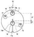
- the two terminal portions 16 and 18 to which the end portions 13 a and 13 b of the conducting wires housed in the groove portions 26 of the front end side wall portion 24 are connected are respectively connected to the coil units 10. They are arranged at different distances from the center (center of the tip surface of the tip insulating portion 11) O.
- the terminal portion 16 to which the end portion 13a of the conducting wire is connected has a center O1 at a position separated from the center O of the tip surface of the coil unit 10 by a length L1.
- the terminal portion 18 to which the end portion 13b of the conducting wire is connected has a length L2 (longer than the length L1 that is the separation distance of the terminal portion 16 from the center O of the tip surface of the coil unit 10.
- the center O2 is provided at a position separated by L1 ⁇ L2).
- the terminal-side insulating portion 11 of the coil unit 10 is arranged such that the terminal portion 16 is close to the center O of the front end surface of the coil unit 10 and the terminal portion 18 is far from the center O of the front end surface of the coil unit 10. Yes.
- terminal portions 15 and 17 constituting a pair of electrical connection terminal portions to which the end portions 13 a and 13 b of the conducting wires are electrically connected via the terminal portions 16 and 18 are arranged at the center O of the distal end surface of the coil unit 10.
- Each of the centers O3 and O4 is located at a position that is point-symmetric with respect to a point, that is, a position rotated 180 degrees with respect to the center O serving as a symmetry point.
- the pair of electrical connection portions 41 and 42 includes a rectangular block-shaped core wire connection portion 43 to which the core wires 31 a and 32 a of the signal lines 31 and 32 are connected, and the distal end side of the coil unit 10.
- This is a conductor member having a substantially U-shaped cross section having a terminal engaging portion 44 in which semicircular portions are opposed to each other so that terminal portions 15 and 17 provided in the insulating portion 11 are engaged with each other.
- the pair of core wire connection portions 43 are connected to the flat portions facing the outside of the coil unit 10 so that the core wires 31 a and 32 a of the signal wires 31 and 32 are soldered by solder or the like. Is electrically connected.
- the signal lines 31 and 32 that are electrically connected to the core wire connection portions 43 of the pair of electrical connection portions 41 and 42 are extended toward the proximal end side of the probe 1.
- the signal lines 31 and 32 are disposed up to the electrical connector portion 3 of the probe 1.
- One electrical connection portion 41 has a core wire connection portion 43 provided on the upper side of the terminal engagement portion 44.
- the core wire connecting portion 43 is provided below the terminal engaging portion 44.
- the one electrical connection portion 41 is disposed below the other electrical connection portion 42 in the distal insulating portion 11. Therefore, the core wire connection portions 43 of the pair of electrical connection portions 41 and 42 are provided at substantially the same height on the side portion of the distal end side insulating portion 11.
- the signal lines 31 and 32 are electrically connected to the core wire connecting portion 43 at a position of substantially the same height on the side portion of the distal end side insulating portion 11.
- one of the signal lines 31 and 32 connected to the pair of electrical connection portions 41 and 42 is a current application cable, and the other is a current feedback cable.
- the two terminal portions 16 and 18 projecting from the vertical direction of the distal end surface of the distal end side insulating portion 11 have the distal end side wall portion 24 of the housing portion 21. It is engaged in the groove part 26 formed in this. That is, the two terminal portions 16 and 18 constitute a mounting direction defining terminal portion that is engaged with the groove portion 26 formed in the distal end side wall portion 24 and defines the mounting direction around the longitudinal axis of the coil unit 10.
- the pair of terminal portions 15 and 17 projecting from the left and right directions of the distal end surface of the distal end side insulating portion 11 and electrically connected to the end portions 13a and 13b of the conducting wires via the terminal portions 16 and 18, As shown in FIG. 9, they are fitted and engaged with the terminal engaging portions 44 of the pair of electrical connection portions 41, 42 provided on the distal end side wall portion 24, respectively, and are held by the terminal engaging portions 44. In this state, it is electrically connected to the pair of electrical connection portions 41 and 42.
- the coil unit 10 is held in contact with a claw portion 25 a in which the outer peripheral surface upper portion of the base end side insulating portion 12 protrudes from the base end side wall portion 25.
- the coil unit 10 has the pair of terminal portions 15 and 17 on the distal end side held by the terminal engaging portions 44 of the pair of electrical connection portions 41 and 42, and the proximal end side provided on the proximal end side wall portion 25. By being held by the claw portion 25a, it is configured to prevent the dropout from the accommodating portion 21.
- the coil unit 10 includes a pair of terminal portions 15 and 17 on the distal end side that are mechanically held by the terminal engaging portions 44 of the pair of electrical connection portions 41 and 42, and the proximal end side is also insulated on the proximal end side. Since the portion 12 is mechanically held by the claw portion 25a provided on the proximal end side wall portion 25, the drop-off from the accommodating portion 21 is prevented.
- the coil unit 10 extracts the pair of terminal portions 15 and 17 on the distal end side from the terminal engaging portions 44 of the pair of electrical connection portions 41 and 42 and provides the proximal end side insulating portion 12 on the proximal end side wall portion 25. It can be easily removed from the accommodating portion 21 by removing the contact from the claw portion 25a.
- the coil unit 10 has one terminal portion 16 accommodated in the groove portion 26 of the distal end side wall portion 24 from the center O of the distal end surface close to the center O of the distal end surface of the coil unit 10, and the other terminal.
- the portion 18 is disposed at a position far from the center O of the front end surface of the coil unit 10.
- the probe 1 according to the present embodiment described above has a plurality of coil units 10 mounted in the respective accommodating portions 21 of the insertion portion 2 so that the plurality of coil units 10 can be accurately positioned as compared with the conventional configuration. It can be installed in the assembly, improving the assembly.
- the probe 1 can be easily maintained even if a defect occurs in one of the coil units 10 because the coil unit 10 to be replaced only needs to be removed from the accommodating portion 21 and the new coil unit 10 is mounted in the accommodating portion 21. Will improve. Thereby, even if a defect occurs in one of the coil units 10, the probe 1 does not need to be completely replaced, and the maintenance cost is also reduced.
- the probe 1 according to the present embodiment can be configured such that the installation of the plurality of coil units 10 is simplified, the assembling property and the maintenance property are improved, and the maintenance cost can be reduced.
- FIG. 11 is a front view showing the configuration of the coil unit provided with the connection terminals of the first modification
- FIG. 12 is a coil unit housing portion in which the coil unit of the first modification is mounted in a predetermined direction.
- FIG. 13 is a sectional view of the coil unit housing portion when the coil unit of the first modification is not mounted in a predetermined direction
- FIG. 14 is connected to the terminal portion of the coil unit of the second modification.
- FIG. 15 is a cross-sectional view of the coil unit housing portion in a state where the coil unit of the second modified example is mounted
- FIG. 16 is a terminal of the coil unit of the third modified example. It is a front view which shows the structure which provided the wall part between the parts.
- the two terminal portions 16 and 18 accommodated in the groove portion 26 of the distal end side wall portion 24 are point-symmetric with respect to the center O of the distal end surface of the coil unit 10. That is, the respective centers O1 and O2 are provided at positions rotated by 180 degrees as the center O serving as a symmetry point.
- the pair of terminal portions 15 and 17 to which the end portions 13a and 13b of the conductive wires are electrically connected via the terminal portions 16 and 18 have their respective centers O3 and O4 from the center O of the distal end surface of the coil unit 10.
- the distances in the horizontal direction (left and right lateral directions), that is, in the direction orthogonal to the mounting direction of the coil unit 10 to the accommodating portion 21 are arranged at the same position.
- one terminal portion 15 has a length L3 in a direction perpendicular to the mounting direction from the center O of the front end surface of the coil unit 10 to the accommodating portion 21 (here, the right side when viewed toward the paper surface).
- the center O3 is located at a predetermined angle ⁇ 1 around the center O (clockwise direction).
- the other terminal portion 17 has the above length in a direction orthogonal to the mounting direction from the center O of the front end surface of the coil unit 10 to the accommodating portion 21 (here, the left side when viewed toward the paper surface).
- the pair of terminal portions 15 and 17 are rotated 180 degrees with respect to the point O with respect to the center O of the front end surface of the coil unit 10, that is, with respect to the center O serving as a symmetry point.
- the configuration does not have the respective centers O3 and O4 at the positions.
- the coil unit 10 of the present modification configured as described above has two terminal portions 16 and 18 formed on the distal end side wall portion 24 of the housing portion 21 when mounted on the housing portion 21.
- the groove 26 is engaged.
- the coil unit 10 is held in contact with a claw portion 25a (see FIG. 4) in which the outer peripheral upper portion of the base end side insulating portion 12 protrudes from the base end side wall portion 25.
- the pair of terminal portions 15 and 17 on the distal end side are held by the terminal engaging portions 44 of the pair of electrical connection portions 41 and 42, and the proximal end side wall portion 25 is on the proximal end side.
- the claw portion 25a provided in the housing it is possible to prevent the housing portion 21 from falling off.
- the coil unit 10 extracts the pair of terminal portions 15 and 17 on the distal end side from the terminal engaging portions 44 of the pair of electrical connection portions 41 and 42 and provides the proximal end side insulating portion 12 on the proximal end side wall portion 25. It can be easily removed from the accommodating portion 21 by removing the contact from the claw portion 25a.
- the pair of terminal portions 15 and 17 is point-symmetric with respect to the center O of the front end surface of the coil unit 10, that is, a symmetry point.
- the center O is not configured to have the respective centers O3 and O4 at positions rotated by 180 degrees.
- the coil unit 10 of the present modification has a non-conductive wall portion 27 formed of a resin or the like that connects the two terminal portions 16 and 18 accommodated in the groove portion 26 of the distal end side wall portion 24. Is provided.
- the wall portion 27 has a width dimension substantially equal to or less than the width dimension of the two terminal portions 16 and 18.
- the coil unit 10 of this modification configured as described above has two terminal portions 16 and 18 formed on the distal end side wall portion 24 of the housing portion 21 when mounted on the housing portion 21.
- the wall portion 27 is provided so that stable assembly can be performed, and the pair of electrical connection portions 41 and 42 are engaged by being engaged with the terminal engagement portions 44.
- the terminal portions 15 and 17 can be easily distinguished from each other.
- the coil unit 10 of the present modification includes a wall portion 11 c that is integrally formed with the distal end side insulating portion 11 between the two terminal portions 16 and 18 that are accommodated in the groove portion 26 of the distal end side wall portion 24. Is provided.
- the wall portion 11c has a width dimension substantially equal to or less than the dimension in the width direction of the two terminal portions 16 and 18.
- two terminal portions 16 and 18 are formed on the distal end side wall portion 24 of the accommodating portion 21 when mounted on the accommodating portion 21 as in the second modified example.
- the wall portion 11c is provided, so that stable assembly can be performed, and the terminal engagement portions 44 of the pair of electrical connection portions 41 and 42 are engaged and engaged.
- the pair of terminal portions 15 and 17 can be easily distinguished from each other.
Abstract
L'invention concerne une sonde d'observation de forme d'insertion d'endoscope (1) qui peut être librement insérée dans un canal formé dans une section d'insertion d'endoscope ou qui est installée dans la section d'insertion d'endoscope, et qui comporte les éléments suivants : un élément électronique (10); une section de réception renfoncée (21) pour loger l'élément électronique (10); une paire de connecteurs électriques (41, 42) placés dans la section de réception (21); et une paire de bornes de raccordement électrique (15, 17) qui sont placées dans l'élément électronique (10), qui sont reliées électriquement à la paire de connecteurs électriques (41, 42) en s'accouplant à ces derniers, et qui maintiennent mécaniquement l'élément électronique (10) dans la section de réception (21).
Priority Applications (2)
| Application Number | Priority Date | Filing Date | Title |
|---|---|---|---|
| JP2015552666A JP5877287B1 (ja) | 2014-07-29 | 2015-03-13 | 内視鏡挿入形状観測プローブ |
| US15/140,688 US9775540B2 (en) | 2014-07-29 | 2016-04-28 | Endoscope insertion shape observation probe |
Applications Claiming Priority (2)
| Application Number | Priority Date | Filing Date | Title |
|---|---|---|---|
| JP2014-154071 | 2014-07-29 | ||
| JP2014154071 | 2014-07-29 |
Related Child Applications (1)
| Application Number | Title | Priority Date | Filing Date |
|---|---|---|---|
| US15/140,688 Continuation US9775540B2 (en) | 2014-07-29 | 2016-04-28 | Endoscope insertion shape observation probe |
Publications (1)
| Publication Number | Publication Date |
|---|---|
| WO2016017202A1 true WO2016017202A1 (fr) | 2016-02-04 |
Family
ID=55217107
Family Applications (1)
| Application Number | Title | Priority Date | Filing Date |
|---|---|---|---|
| PCT/JP2015/057465 WO2016017202A1 (fr) | 2014-07-29 | 2015-03-13 | Sonde d'observation de forme d'insertion d'endoscope |
Country Status (3)
| Country | Link |
|---|---|
| US (1) | US9775540B2 (fr) |
| JP (1) | JP5877287B1 (fr) |
| WO (1) | WO2016017202A1 (fr) |
Cited By (2)
| Publication number | Priority date | Publication date | Assignee | Title |
|---|---|---|---|---|
| JP2017169994A (ja) * | 2016-03-25 | 2017-09-28 | Hoya株式会社 | 内視鏡先端位置特定システム |
| FR3133974A1 (fr) | 2022-04-05 | 2023-10-06 | La Source | Système aquaponique découplé en eau faiblement salée et procédé d’élevage et de culture dans tel système |
Families Citing this family (2)
| Publication number | Priority date | Publication date | Assignee | Title |
|---|---|---|---|---|
| WO2018042271A1 (fr) * | 2016-09-01 | 2018-03-08 | St. Jude Medical International Holding S.À R.L. | Conceptions d'âmes pour capteurs de bobine inductifs miniatures |
| US11045109B2 (en) * | 2016-10-26 | 2021-06-29 | St. Jude Medical, Cardiology Division, Inc. | Navigational electrode with magnetic tracking coil |
Citations (6)
| Publication number | Priority date | Publication date | Assignee | Title |
|---|---|---|---|---|
| JPS649689A (en) * | 1987-07-02 | 1989-01-12 | Sony Corp | Circuit board |
| JPH0682770U (ja) * | 1992-12-04 | 1994-11-25 | 住友電装株式会社 | コネクタ |
| JPH1075929A (ja) * | 1996-09-06 | 1998-03-24 | Olympus Optical Co Ltd | 内視鏡位置検出用コイル装置 |
| JP2011253644A (ja) * | 2010-05-31 | 2011-12-15 | Yazaki Corp | コネクタ端子 |
| WO2013039059A1 (fr) * | 2011-09-15 | 2013-03-21 | オリンパスメディカルシステムズ株式会社 | Sonde de détection de la position d'un endoscope |
| JP5444522B1 (ja) * | 2012-07-13 | 2014-03-19 | オリンパスメディカルシステムズ株式会社 | プローブ及び内視鏡 |
Family Cites Families (4)
| Publication number | Priority date | Publication date | Assignee | Title |
|---|---|---|---|---|
| US5997473A (en) | 1996-09-06 | 1999-12-07 | Olympus Optical Co., Ltd. | Method of locating a coil which consists of determining the space occupied by a source coil generating a magnetic field |
| US6745065B2 (en) * | 2001-08-02 | 2004-06-01 | Olympus Corporation | Endoscope apparatus |
| JP4481711B2 (ja) * | 2004-04-09 | 2010-06-16 | オリンパス株式会社 | 挿入形状検出プローブ |
| US8504139B2 (en) * | 2009-03-10 | 2013-08-06 | Medtronic Xomed, Inc. | Navigating a surgical instrument |
-
2015
- 2015-03-13 WO PCT/JP2015/057465 patent/WO2016017202A1/fr active Application Filing
- 2015-03-13 JP JP2015552666A patent/JP5877287B1/ja active Active
-
2016
- 2016-04-28 US US15/140,688 patent/US9775540B2/en active Active
Patent Citations (6)
| Publication number | Priority date | Publication date | Assignee | Title |
|---|---|---|---|---|
| JPS649689A (en) * | 1987-07-02 | 1989-01-12 | Sony Corp | Circuit board |
| JPH0682770U (ja) * | 1992-12-04 | 1994-11-25 | 住友電装株式会社 | コネクタ |
| JPH1075929A (ja) * | 1996-09-06 | 1998-03-24 | Olympus Optical Co Ltd | 内視鏡位置検出用コイル装置 |
| JP2011253644A (ja) * | 2010-05-31 | 2011-12-15 | Yazaki Corp | コネクタ端子 |
| WO2013039059A1 (fr) * | 2011-09-15 | 2013-03-21 | オリンパスメディカルシステムズ株式会社 | Sonde de détection de la position d'un endoscope |
| JP5444522B1 (ja) * | 2012-07-13 | 2014-03-19 | オリンパスメディカルシステムズ株式会社 | プローブ及び内視鏡 |
Cited By (3)
| Publication number | Priority date | Publication date | Assignee | Title |
|---|---|---|---|---|
| JP2017169994A (ja) * | 2016-03-25 | 2017-09-28 | Hoya株式会社 | 内視鏡先端位置特定システム |
| FR3133974A1 (fr) | 2022-04-05 | 2023-10-06 | La Source | Système aquaponique découplé en eau faiblement salée et procédé d’élevage et de culture dans tel système |
| WO2023194684A1 (fr) | 2022-04-05 | 2023-10-12 | La Source | Système aquaponique découplé en eau faiblement salée et procédé d'élevage et de culture dans tel système |
Also Published As
| Publication number | Publication date |
|---|---|
| JPWO2016017202A1 (ja) | 2017-04-27 |
| US9775540B2 (en) | 2017-10-03 |
| US20160235338A1 (en) | 2016-08-18 |
| JP5877287B1 (ja) | 2016-03-02 |
Similar Documents
| Publication | Publication Date | Title |
|---|---|---|
| JP6033333B2 (ja) | ビデオ内視鏡のための電気接続部品、ビデオ内視鏡、及びビデオ内視鏡の電気接続の作成方法 | |
| JP5877287B1 (ja) | 内視鏡挿入形状観測プローブ | |
| US9401550B2 (en) | Connector | |
| JP2008147030A (ja) | 分岐コネクタ | |
| WO2015037216A1 (fr) | Élément de support de câble, dispositif de connexion électrique, dispositif de connecteur et câble plat | |
| US11228145B2 (en) | Communication connector | |
| US9929483B2 (en) | Electrical connection piece for an endoscope and method for establishing an electrical connection in an endoscope | |
| JP2005531119A (ja) | 電線処理モジュールを備えた電気コネクタ | |
| US20170256894A1 (en) | Communication connector | |
| JP2015520498A (ja) | 差込式コネクタの絶縁体 | |
| US10374367B2 (en) | Communication connector and housing with a metal partition wall between wires | |
| TW200814440A (en) | Connector and connector system | |
| CN105284008B (zh) | 缆线连接构造 | |
| JP2016195038A (ja) | プラグ | |
| TW201112534A (en) | Connector, cable assembly, and semiconductor testing device | |
| CN108206346B (zh) | 插头 | |
| JP6701894B2 (ja) | コネクタ及びワイヤハーネス | |
| JP5203273B2 (ja) | プラグイン器具 | |
| JP2016054131A (ja) | コネクタの接続構造 | |
| JP5359321B2 (ja) | アース接続用配線材、これに用いられるジョイントコネクタ、及びアース接続用配線材が組み込まれたワイヤハーネス | |
| JP6091330B2 (ja) | 測定装置 | |
| JP7082521B2 (ja) | 蓄電装置 | |
| KR20150001973U (ko) | 커넥터를 갖는 다심 케이블 | |
| US9634443B2 (en) | Connector and contact | |
| US20230318233A1 (en) | Connector and cable with connector |
Legal Events
| Date | Code | Title | Description |
|---|---|---|---|
| ENP | Entry into the national phase |
Ref document number: 2015552666 Country of ref document: JP Kind code of ref document: A |
|
| 121 | Ep: the epo has been informed by wipo that ep was designated in this application |
Ref document number: 15827746 Country of ref document: EP Kind code of ref document: A1 |
|
| NENP | Non-entry into the national phase |
Ref country code: DE |
|
| 122 | Ep: pct application non-entry in european phase |
Ref document number: 15827746 Country of ref document: EP Kind code of ref document: A1 |