WO2016017136A1 - 制御情報検出装置および制御情報検出方法 - Google Patents
制御情報検出装置および制御情報検出方法 Download PDFInfo
- Publication number
- WO2016017136A1 WO2016017136A1 PCT/JP2015/003739 JP2015003739W WO2016017136A1 WO 2016017136 A1 WO2016017136 A1 WO 2016017136A1 JP 2015003739 W JP2015003739 W JP 2015003739W WO 2016017136 A1 WO2016017136 A1 WO 2016017136A1
- Authority
- WO
- WIPO (PCT)
- Prior art keywords
- vehicle
- control information
- captured image
- camera
- image
- Prior art date
- Legal status (The legal status is an assumption and is not a legal conclusion. Google has not performed a legal analysis and makes no representation as to the accuracy of the status listed.)
- Ceased
Links
Images







Classifications
-
- G—PHYSICS
- G01—MEASURING; TESTING
- G01B—MEASURING LENGTH, THICKNESS OR SIMILAR LINEAR DIMENSIONS; MEASURING ANGLES; MEASURING AREAS; MEASURING IRREGULARITIES OF SURFACES OR CONTOURS
- G01B11/00—Measuring arrangements characterised by the use of optical techniques
- G01B11/24—Measuring arrangements characterised by the use of optical techniques for measuring contours or curvatures
- G01B11/245—Measuring arrangements characterised by the use of optical techniques for measuring contours or curvatures using a plurality of fixed, simultaneously operating transducers
-
- G—PHYSICS
- G01—MEASURING; TESTING
- G01C—MEASURING DISTANCES, LEVELS OR BEARINGS; SURVEYING; NAVIGATION; GYROSCOPIC INSTRUMENTS; PHOTOGRAMMETRY OR VIDEOGRAMMETRY
- G01C3/00—Measuring distances in line of sight; Optical rangefinders
- G01C3/02—Details
- G01C3/06—Use of electric means to obtain final indication
-
- G—PHYSICS
- G06—COMPUTING OR CALCULATING; COUNTING
- G06T—IMAGE DATA PROCESSING OR GENERATION, IN GENERAL
- G06T7/00—Image analysis
- G06T7/20—Analysis of motion
-
- G—PHYSICS
- G06—COMPUTING OR CALCULATING; COUNTING
- G06T—IMAGE DATA PROCESSING OR GENERATION, IN GENERAL
- G06T7/00—Image analysis
- G06T7/60—Analysis of geometric attributes
Definitions
- the present disclosure is applied to a vehicle including a plurality of in-vehicle cameras, and relates to a technique for analyzing control images acquired from the plurality of in-vehicle cameras and detecting control information for controlling traveling of the vehicle.
- the inventors of the present application found the following. In order to extract some information from multiple images taken by multiple in-vehicle cameras, there was a problem that the shooting timings had to be synchronized so that the multiple in-vehicle cameras shot images at the same timing. . This is because the vehicle can travel at a high speed, and if the timing at which the in-vehicle camera captures an image is shifted, the vehicle moves a long distance during that time, which is a major error factor. .
- This disclosure is intended to provide a technique capable of extracting information from images of in-vehicle cameras without synchronizing a plurality of in-vehicle cameras.
- the plurality of vehicle-mounted cameras are mounted on a vehicle including a plurality of vehicle-mounted cameras that output a captured image captured at a predetermined shooting cycle after being divided into a plurality of field images by an interlace method.
- a control information detection device that detects control information for controlling the traveling of the vehicle by analyzing a captured image acquired from the camera.
- the control information detection apparatus acquires, for each of the plurality of vehicle-mounted cameras, the captured image that is output in units of field images each time the vehicle-mounted camera captures a captured image and stores the captured image.
- a storage unit and a control information acquisition unit that acquires a control information by analyzing a plurality of captured images stored for each in-vehicle camera.
- the photographed image storage unit stores the photographed image in a readable state in units of field images.
- the control information acquisition unit acquires the control information by reading the most recently acquired field image for each in-vehicle camera from the captured image storage unit and analyzing it as a captured image.
- the plurality of vehicle-mounted cameras are applied to a vehicle including a plurality of vehicle-mounted cameras that output a captured image captured at a predetermined imaging cycle after being divided into a plurality of field images by an interlace method.
- a control information detection method for detecting control information for controlling the traveling of the vehicle by analyzing a captured image acquired from the camera is provided.
- the captured image output in units of field images is acquired every time the vehicle-mounted camera captures a captured image, and the captured image is stored for each of the plurality of vehicle-mounted cameras.
- the captured image storage step the captured image is stored in a state where it can be read out in units of field images.
- a control information acquisition process acquires control information by reading the field image acquired most recently for every vehicle-mounted camera, and analyzing it as a picked-up image.
- control information detection apparatus and the control information detection method of the present disclosure it is only necessary to acquire the most recent field image from each in-vehicle camera, and thus it is not necessary for the in-vehicle camera to capture a plurality of captured images. For this reason, it is possible to avoid a situation in which the vehicle travels a long distance while a plurality of in-vehicle cameras capture a captured image. As a result, even when the shooting timings of the plurality of in-vehicle cameras are not synchronized, information can be extracted from the captured images of the plurality of in-vehicle cameras. According to the control information detection device and the control information detection method of the present disclosure, it is possible to extract information from the images of the in-vehicle cameras without synchronizing the plurality of in-vehicle cameras.
- FIG. 1 is a block diagram showing a rough internal configuration of the control information detecting apparatus according to the first embodiment.
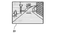
- FIG. 2A is an explanatory diagram illustrating a field image.
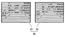
- FIG. 2B is an explanatory diagram illustrating a field image.
- FIG. 2C is an explanatory diagram illustrating a field image.
- FIG. 3 is a flowchart of the control information detection process executed by the control information detection device,
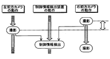
- FIG. 4 is an explanatory diagram illustrating the relationship between the operation of the left front camera and the right front camera in the comparative example and the operation of the control information detection device, FIG.
- FIG. 5 is an explanatory diagram illustrating the relationship between the operation of the left front vehicle camera and the right front vehicle camera and the operation of the control information detection device
- FIG. 6A is an explanatory diagram showing a difference in magnitude of a photographing time difference between two field images to be read in a comparative example
- FIG. 6B is an explanatory diagram showing the difference in the magnitude of the difference in shooting time between two field images to be read in the case of the present embodiment.
- FIG. 7A is a block diagram showing a rough internal configuration of the control information detecting apparatus according to the second embodiment.
- FIG. 7B is a block diagram showing a rough internal configuration of the control information detecting apparatus according to the second embodiment.
- FIG. 8 is a flowchart of the control information detection process executed by the control information detection device, FIG.
- FIG. 9 is an explanatory diagram showing a state of collation of the estimated lane boundary
- FIG. 10 is another explanatory view showing a state of collation of the estimated lane boundary.
- FIG. 11 is a flowchart of the shortest shooting order determination process executed by the control information detection apparatus according to the modification of the second embodiment.
- FIG. 12 is an explanatory diagram showing the difference in required time between when the field information is read by the control information detecting device and when it falls under the shortest shooting order.
- FIG. 1 shows a rough internal configuration of a vehicle 1 equipped with a control information detection device 10.
- the vehicle 1 includes a control information detection device 10, a left front in-vehicle camera 11, a right front in-vehicle camera 12, and a vehicle control unit 17.
- the control information detection device 10 of this embodiment is a device for detecting control information for controlling the traveling of the vehicle 1 from images taken by the left front vehicle-mounted camera 11 and the right front vehicle-mounted camera 12.
- the left front vehicle-mounted camera 11 and the right front vehicle-mounted camera 12 are video cameras that have overlapping shooting areas and shoot the front of the vehicle 1 at a predetermined cycle.
- the left front in-vehicle camera 11 and the right front in-vehicle camera 12 thin out a plurality of scanning lines by an interlace method in which a still image for one frame, which is a unit constituting an image, is scanned over each scanning line.
- the image is divided into field images 20 in the state of being output and output to the control information detection apparatus 10.
- the field image 20 includes an odd-numbered field image 21 and an even-numbered field image 22 described below, and these are output alternately and repeatedly.
- the left front in-vehicle camera 11 and the right front in-vehicle camera 12 correspond to the “in-vehicle camera” of the present disclosure.
- the field image 20 of this embodiment shown in FIG. 2B includes an odd field image 21 that thins out even-numbered scanning lines and outputs odd-numbered scanning lines, and an even-numbered scanning line by thinning out odd-numbered scanning lines. There is an even field image 22 to be output.
- the frame image 23 shown in FIG. 2A which is a still image for one frame, is obtained.
- the control information detection apparatus 10 includes a left captured image storage unit 31 that stores an image captured by the left front in-vehicle camera 11 and a right captured image storage unit that stores an image captured by the right front in-vehicle camera 12. 32, a control information acquisition unit 38 that acquires control information for controlling the vehicle 1 by analyzing the captured image, and a control information output unit 39 that outputs the control information to the vehicle control unit 17.
- the left captured image storage unit 31, the right captured image storage unit 32, the control information acquisition unit 38, and the control information output unit 39 do not represent that the inside of the control information detection device 10 is physically partitioned. This is a concept in which the functions performed by the control information detection device 10 are classified. Therefore, these “units” can be realized as a computer program executed by the CPU, can be realized as an electronic circuit including an LSI and a memory, or can be realized by combining them.
- the left photographed image storage unit 31 stores a field image 20 that is a photographed image acquired in synchronization with the photographing cycle of the left front vehicle-mounted camera 11. As described above, since the left front in-vehicle camera 11 alternately outputs the odd field image 21 and the even field image 22, the left captured image storage unit 31 also stores the odd field image 21 and the even field image 22 alternately. It will be. Similarly, the right photographed image storage unit 32 stores the field image 20 acquired in synchronization with the photographing cycle of the right front vehicle-mounted camera 12.
- the left captured image storage unit 31 and the right captured image storage unit 32 that store the field image 20 as described above hold the most recent field image 20 among the stored field images 20 in a readable state.
- the control information acquisition unit 38 can acquire the latest field image 20 from the left captured image storage unit 31 and the right captured image storage unit 32.
- the left captured image storage unit 31 and the right captured image storage unit 32 are time lags generated between the output cycle from the left front vehicle-mounted camera 11 and the right front vehicle-mounted camera 12 and the processing cycle of the control information acquisition unit 38. It is a buffer memory for absorbing water.
- the left captured image storage unit 31 and the right captured image storage unit 32 correspond to the “captured image storage unit” of the present disclosure.
- the control information acquisition unit 38 detects information for controlling the vehicle 1 by analyzing the field image 20 stored in the left captured image storage unit 31 and the field image 20 stored in the right captured image storage unit 32. To do. Examples of observation objects for analysis include, but are not limited to, pedestrians, road obstacles, lanes, traffic signs, and the like, and any object that can grasp the situation around the vehicle 1 is an observation object. can do.
- the field image 20 in a state where some of the scanning lines are thinned out may be analyzed as it is, or an odd row or even number may be determined depending on the obtained image information of the odd field image 21 or even field image 22.
- the analysis may be performed after interpolating the scanning line in which one of the columns is thinned out. Further, by determining whether the field image 20 to be analyzed is an odd field image 21 or an even field image 22 by using a synchronization signal, it is possible to prevent errors caused by mistaking the odd and even columns. .
- the control information output unit 39 outputs information for controlling the vehicle 1 acquired by the control information acquisition unit 38 to the vehicle control unit 17.
- the vehicle control unit 17 controls the vehicle 1 according to the control information output from the control information output unit 39 included in the control information detection device 10.
- the control of the vehicle 1 includes, for example, driving assistance such as accelerating / decelerating the vehicle 1 or changing the steering angle, and issuing a warning or warning to the driver.
- driving assistance such as accelerating / decelerating the vehicle 1 or changing the steering angle
- Various controls are widely included.
- FIG. 3 shows a flowchart of the control information detection process executed by the control information detection apparatus 10 of this embodiment.
- This control information detection process is a process executed in synchronization with the imaging period of the left front in-vehicle camera 11 and the right front in-vehicle camera 12.
- the field images 20 respectively output from the left front in-vehicle camera 11 and the right front in-vehicle camera 12 are stored (S101).
- the process of S101 corresponds to a captured image storage process. Since shooting is continuously performed, the stored field images 20 are accumulated, but the field image 20 newly stored for each of the left front in-vehicle camera 11 and the right front in-vehicle camera 12 can be analyzed. deep. The old field image 20 may be deleted or saved as needed.
- the stored field image 20 output from the left front in-vehicle camera 11 and the field image 20 output from the right front in-vehicle camera 12 are analyzed to obtain control information for controlling the vehicle 1.
- the process of S102 corresponds to a control information acquisition process.
- the analysis target is not a frame unit but a field unit of either the odd field image 21 or the even field image 22.
- the acquired control information is output to the vehicle control unit 17 (S103), and the control information detection process ends.
- the vehicle control unit 17 can control the vehicle 1 using the control information acquired in this way.
- FIG. 4 shows the timing at which the left front camera and the right front camera capture an odd field image and an even field image, and the timing at which the control information detection device detects control information, taking a time axis that flows downward. It is shown. As shown in the drawing, each of the left front camera and the right front camera alternately captures an odd field image or an even field image at the same cycle, and the control information detection device repeats detection of control information in synchronization with the camera shooting cycle. . Then, the control information detection apparatus of this comparative example reads out both the odd field image and the even field image from the left front camera and detects the odd field image and the even field image from the right front camera for one control information detection. Both are being read out.
- FIG. 5 shows the relationship between the operation of the left front in-vehicle camera 11 and the right front in-vehicle camera 12 and the operation of the control information detection device 10 in the case of the present embodiment.
- the control information detection apparatus 10 of the present embodiment reads only the even field image 22 from each of the left front in-vehicle camera 11 and the right front in-vehicle camera 12, and the scanning lines are thinned out. Control information is detected in the state. At this time, the odd field images 21 output from the left front in-vehicle camera 11 and the right front in-vehicle camera 12 are not used for detection of control information.
- the control information detection apparatus 10 reads only the even field image 22 when detecting control information next time.
- the control information detection apparatus 10 of the present embodiment repeats such processing at a predetermined cycle.
- the present invention is not limited to the above example, and only the odd field image 21 may be read from the left front in-vehicle camera 11 and the right front in-vehicle camera 12 as in the case of control information detection surrounded by a broken line at the bottom of FIG.
- the odd field image 21 may be read from one in-vehicle camera and the even field image 22 may be read from the other in-vehicle camera.
- control information detection apparatus 10 determines whether the field image 20 captured most recently in each of the left front in-vehicle camera 11 and the right front in-vehicle camera 12 is an odd field image 21 or an even field image 22. Read regardless.
- 6A and 6B show the relationship between the operation of the left front vehicle-mounted camera 11 and the right front vehicle-mounted camera 12 and the operation of the control information detection device 10 in the case of the comparative example and the case of the present embodiment. The difference in magnitude of the shooting time difference is shown.
- the shooting time of the odd-numbered field image of the right front camera that was shot first is greatly different from the shooting time of the even-numbered field image of the left front camera that was shot most recently (FIG. 6A). Rightmost arrow). Due to the difference in shooting time, the even field image of the left front camera is shot from a different position as the vehicle travels after shooting the odd field image of the right front camera. For this reason, a case where the traveling speed of the vehicle is sufficiently small is taken as a subject of photographing, or in order to solve the problem of deviation in photographing time, the photographing periods of the two on-vehicle cameras are synchronized.
- the time difference between the time when the right front in-vehicle camera 12 takes a picture and the time when the left front in-vehicle camera 11 takes a picture is smaller than that in the comparative example. (FIG. 6B right end arrow).
- the unit of the field image 20 is set as an analysis target, and the difference in shooting time is reduced. Can be reduced.
- the control information detection apparatus 10 according to the present embodiment does not synchronize the shooting periods of the left front in-vehicle camera 11 and the right front in-vehicle camera 12 even when the traveling speed of the vehicle 1 increases. And it becomes possible to acquire information by analyzing the image taken by the right front in-vehicle camera 12.
- the cycle of the control information detection process is synchronized with the imaging cycle of the left front vehicle-mounted camera 11 and the right front vehicle-mounted camera 12.
- the control information detection processing is similarly performed at about 33 msec. Can be executed for each.
- processing can be performed in the same cycle, but processing is performed using both the odd field image 21 and the even field image 22 in a single control information detection process. Therefore, the cycle of the control information detection process cannot be further shortened with respect to this shooting cycle.
- the control information detection process can be executed every about 16.6 msec with respect to the same shooting period. This will be described below.
- the control information detection apparatus 210 reads the odd field image 221 or the even field image 222 and processes it in units of the field image 220.
- FIG. 7A and 7B show a rough internal configuration of the vehicle 201 on which the control information detection device 210 is mounted.
- two in-vehicle cameras the left front in-vehicle camera 11 and the right front in-vehicle camera 12, are provided in front of the vehicle 1, but in the present embodiment, the front in-vehicle camera 213, the left in-vehicle camera 214, and the right There are four on-vehicle cameras, a side-mounted camera 215 and a rear-mounted camera 216.
- a front shot image storage unit 233, a left shot image storage unit 234, a right shot image storage unit 235, and a rear shot image storage unit 236 are provided.
- Other configurations include a vehicle control unit 217, a vehicle information acquisition unit 238, and a control information output unit 239, as in the first embodiment.
- the left in-vehicle camera 214 and the right in-vehicle camera 215 correspond to the “side in-vehicle camera” of the present disclosure. Further, the front shot image storage unit 233, the left shot image storage unit 234, the right shot image storage unit 235, and the rear shot image storage unit 236 correspond to the “shot image storage unit” of the present disclosure.
- the lane boundary 240 targeted in the present embodiment is a thing that exists almost in parallel with the extension direction of the lane to the extent that the positional relationship between the vehicle 201 and the lane can be grasped.
- Typical examples include white lines drawn on roads such as the Chuo Line and the road outside line, but also other boundary blocks and protective fences that separate road fences, roads and sidewalks embedded along the lane. Or a protective wall can be detected as the lane boundary 240.
- lane boundary 240 In general, when such a lane boundary 240 is detected from a captured image, an edge of a photographed object is extracted from the luminance distribution of the captured image, and the lane boundary 240 to be observed is detected from the various edges. Will be. However, since there are things on the road that are confusing with the lane boundary 240 such as the shadow of the vehicle and the boundary of the asphalt pavement, it is not easy to detect these and the lane boundary 240 separately.
- the control information detection device 210 of the present embodiment is a device for detecting the lane boundary 240 more reliably.
- FIG. 8 shows a flowchart of control information detection processing executed by the control information detection apparatus 210 of this embodiment. Similar to the first embodiment, this control information detection process is also executed in synchronization with the shooting periods of the four in-vehicle cameras: the front in-vehicle camera 213, the left in-vehicle camera 214, the right in-vehicle camera 215, and the rear in-vehicle camera 216. Process.
- the field image 220 output from each of the four in-vehicle cameras is read (S201).
- the field image 220 to be read may be read out regardless of whether it is the odd field image 221 or the even field image 222 as in the first embodiment.
- a lane boundary estimated portion 241 is detected from each of the read four field images 220 (S202).
- the lane boundary estimated portion 241 is detected as being estimated as the lane boundary 240 when an edge that can be determined as the lane boundary 240 is detected from the field image 220.
- the control information detection process is terminated.
- the detected plurality of lane boundary estimated portions 241 are collated with each other (S204), and it is determined whether or not they match. (S205).
- FIG. 9 shows how the lane boundary estimated portion 241 is collated.
- a front shot image 253, a left shot image 254, and a right shot image 255 which are field images 220 shot by the front vehicle camera 213, the left vehicle camera 214, the right vehicle camera 215, and the rear vehicle camera 216, respectively.
- the rear photographed image 256 is converted and arranged as seen from above the vehicle 201.
- the illustration of the bird's-eye view image is merely for convenience of explanation, and it is not always necessary to convert it to the bird's-eye view image in this way.
- the lane boundary estimation portion 241 a is detected from the front shot image 253, the lane boundary estimation portion 241 b is detected from the left shot image 254, and the lane boundary estimation portion 241 c is detected from the rear shot image 256. Since the times at which these estimated lane boundary points 241a, 241b, and 241c are photographed are different from each other, the positional relationship between these images is photographed by the amount of travel of the vehicle 201.
- the lane boundary estimated portion 241b detected in the left-side captured image 254 is extended to the area of the front captured image 253 to be a lane boundary estimated portion 241b '(shaded portion in FIG. 9), this lane boundary estimated portion 241b' And the positional relationship with the estimated lane boundary location 241a detected from the forward captured image 253 can be collated.
- Whether or not the lane boundary estimation part 241b ′ and the lane boundary estimation part 241a coincide with each other is determined by the degree of approximation of both.
- the degree of approximation may be determined by setting an arbitrary threshold value.
- the lane boundary estimation portion 241b ′ and the lane boundary estimation portion 241a are detected in an overlapping manner, or detected by contact as shown in FIG. In this case, since they coincide with each other, it is considered that there is no particular problem in determining that the same single lane boundary 240 has been detected.
- control information detection apparatus 210 of this embodiment can reduce the influence of the shift of the shooting cycle by processing in units of the field image 220 as in the first embodiment. As shown, the amount of displacement of the estimated lane boundary locations 241a, 241b, 241c can be reduced. Accordingly, it is possible to avoid the lane boundary 240 from being confused with the lane boundary 240 such as the shadow of the vehicle or the asphalt pavement, and to detect the lane boundary 240 more reliably.
- the lane boundary 240 appears twice as the vehicle moves. Therefore, it becomes difficult to detect the edge.
- the analysis target is the unit of the field image 220 as in the present embodiment, it is possible to eliminate the difficulty of detecting an edge due to such double projection.
- a plurality of detected lane boundary estimation points 241 can be collated with each other (S204), and it can be determined whether or not they match (S205).
- the control information detection device 210 outputs the position of the lane boundary 240 that is more reliably detected as control information for controlling the vehicle 201 and has high reliability.
- the position of the lane boundary 240 to be output is determined from an image (left captured image 254 or right captured image 255) captured from the left in-vehicle camera 214 or the right in-vehicle camera 215 provided on the side of the vehicle 201. It is good to detect. Note that the left-side captured image 254 or the right-side captured image 255 corresponds to the side-captured image.
- the lane boundary 240 that is the detection target can be photographed from a closer position, and errors in the position of the lane boundary 240 with respect to the vehicle 201 caused by detection can be reduced.
- the vehicle 201 tilts and affects the positional relationship between the in-vehicle camera and the lane boundary 240, but the left in-vehicle camera 214 provided on the side of the vehicle 201.
- the influence of the right in-vehicle camera 215 is relatively smaller than the influence of the front in-vehicle camera 213 or the rear in-vehicle camera 216.
- the position of the lane boundary 240 detected from the image (front-captured image 253 or rear-captured image 256) captured from the front in-vehicle camera 213 or the rear in-vehicle camera 216 can also be output.
- the lane boundary 240 is detected from a wide different shooting area, that is, a shooting area on the side of the vehicle 201 and a shooting area on the front (or the rear), compared to the case where it is detected by any one of the vehicle-mounted cameras alone. Since the lane boundary 240 of a longer distance can be confirmed, it is possible to reduce the possibility of erroneous detection such as detecting something other than the lane boundary 240.
- the control information detection apparatus 310 further includes a shooting order acquisition unit 361, a required time calculation unit 362, and a shortest shooting order determination unit 363 in addition to the control information detection apparatus 210 according to the second embodiment. ing.
- the shortest shooting order determination process executed by these will be described with reference to the functions of the respective units.
- FIG. 11 shows a flowchart of the shortest shooting order determination process executed by the control information detection apparatus 310 of this modification. This shortest shooting order determination process is executed prior to the control information detection process described in the second embodiment.
- the shooting order acquisition unit 361 acquires the shooting order of the four in-vehicle cameras and the time interval between the in-vehicle cameras (S251).
- the imaging order of the four in-vehicle cameras represents the order in which the front in-vehicle camera 213, the left in-vehicle camera 214, the right in-vehicle camera 215, and the rear in-vehicle camera 216 capture images. .
- these four in-vehicle cameras shoot at the same shooting cycle, but the timing for starting the shooting is shifted. Accordingly, the front in-vehicle camera 213, the left in-vehicle camera 214, the right in-vehicle camera 215, and the rear in-vehicle camera 216 capture images in a certain order determined by the timing of the start of imaging.
- the shooting order of the in-vehicle camera refers to the order determined in this way. For example, if the order of starting shooting is the front in-vehicle camera 213, the left in-vehicle camera 214, the right in-vehicle camera 215, and the rear in-vehicle camera 216, the imaging order is the front in-vehicle camera 213, the left in-vehicle camera 214, The right in-vehicle camera 215 and the rear in-vehicle camera 216 are provided.
- the shooting order circulates (when the head of the order is the front in-vehicle camera 213, the end is also the front in-vehicle camera 213).
- the imaging order is the front in-vehicle camera 213, the left in-vehicle camera 214, and the right in-vehicle camera.
- the shooting order is the same as the left in-vehicle camera 214, the right in-vehicle camera 215, the rear in-vehicle camera 216, the front in-vehicle camera 213, and the left in-vehicle camera 214. Treat as shooting order.
- the time interval between the four in-vehicle cameras refers to the time interval between the in-vehicle cameras in the adjacent order when the four in-vehicle cameras are photographed in the photographing order. Therefore, when the above shooting sequence is the front in-vehicle camera 213, the left in-vehicle camera 214, the right in-vehicle camera 215, the rear in-vehicle camera 216, and the front in-vehicle camera 213, the following time intervals are acquired. Become. That is, four time intervals of the front vehicle camera 213 and the left vehicle camera 214, the left vehicle camera 214 and the right vehicle camera 215, the right vehicle camera 215 and the rear vehicle camera 216, the rear vehicle camera 216, and the front vehicle camera 213. It is.
- the required time calculation unit 362 selects one vehicle-mounted camera from the four vehicle-mounted cameras (S252), and calculates the time required for all other vehicle-mounted cameras to shoot after the selected vehicle-mounted camera captures images. Calculate (S253). This required time can be easily calculated by using the time interval between the four in-vehicle cameras acquired by the above processing (S251).
- the shortest imaging order determination unit 363 determines the shortest imaging order that minimizes the required time (S255). The processing for determining the shortest photographing order is executed by selecting the shortest case from the four required times calculated by the above processing.
- the control information detection process is executed as in the second embodiment.
- the reading of the four field images 220 (S201) by the control information acquisition unit 238 is determined as described above.
- the shortest shooting sequence will be followed. That is, the control information acquisition unit 238 reads the field image 220 for each in-vehicle camera at a timing at which the order in which the latest field images 220 read for each in-vehicle camera are acquired is the shortest imaging order.
- FIG. 12 shows the difference in the required time when the shortest shooting order is applicable and when it is not applicable.
- the upper detection timing C is an example when it does not correspond to the shortest imaging order.
- the required time at this time is the time required from when the front in-vehicle camera 213 takes an image to when the rear in-vehicle camera 216 takes an image, and is ⁇ 1. Even in this case, since it corresponds to the control information detection process of the second embodiment, the influence of the shift of the imaging cycle between the four in-vehicle cameras is less than that of the comparative example.
- the required time at this time is a time required from when the left in-vehicle camera 214 takes an image to when the front in-vehicle camera 213 takes an image, and is ⁇ 2. Comparing the above ⁇ 1 and ⁇ 2, it can be seen that the influence of the shift in the shooting period reduced by the second embodiment is further reduced by executing the shortest shooting order determination process of the present modification.
- captured images output in units of field images from a plurality of in-vehicle cameras are stored for each in-vehicle camera, and captured images of the plurality of in-vehicle cameras are stored.
- control information for controlling the running of the vehicle is detected.
- the field image acquired most recently for each in-vehicle camera is analyzed.
- each step is expressed as S101, for example. Further, each step can be divided into a plurality of sub-steps, while a plurality of steps can be combined into one step.
- the embodiment, configuration, and aspect of the control information detection apparatus and control information detection method according to the present disclosure have been exemplified, but the embodiment, configuration, and aspect according to the present disclosure are the embodiments, configurations, and aspects described above. It is not limited to.
- embodiments, configurations, and aspects obtained by appropriately combining technical sections disclosed in different embodiments, configurations, and aspects are also included in the scope of the embodiments, configurations, and aspects according to the present disclosure.
Landscapes
- Physics & Mathematics (AREA)
- Engineering & Computer Science (AREA)
- General Physics & Mathematics (AREA)
- Theoretical Computer Science (AREA)
- Computer Vision & Pattern Recognition (AREA)
- Multimedia (AREA)
- Geometry (AREA)
- Electromagnetism (AREA)
- Radar, Positioning & Navigation (AREA)
- Remote Sensing (AREA)
- Image Analysis (AREA)
- Length Measuring Devices By Optical Means (AREA)
- Measurement Of Optical Distance (AREA)
- Traffic Control Systems (AREA)
Abstract
制御情報検出装置は、複数のフィールド画像に分けた後に出力する車載カメラ(11,12)を、複数備える車両(1)に搭載されて、撮影画像を解析し、車両の走行を制御するための制御情報を検出する。制御情報検出装置は、車載カメラが撮影画像を撮影する度にフィールド画像の単位で出力する該撮影画像を取得して、複数の車載カメラ毎に記憶する撮影画像記憶部(31,32)と、制御情報を取得する制御情報取得部(38)とを備える。撮影画像記憶部は、撮影画像を、フィールド画像の単位で読み出し可能な状態で記憶する。制御情報取得部は、フィールド画像を撮影画像記憶部から読み出して、撮影画像として解析し、制御情報を取得する。
Description
本開示は、2014年7月30日に出願された日本国特許出願2014-154628号に基づくもので、ここにその記載内容を援用する。
本開示は、複数の車載カメラを備える車両に適用されて、複数の車載カメラから取得した撮影画像を解析して、車両の走行を制御するための制御情報を検出する技術に関する。
近年では、車両が車線を維持できるように支援したり、車線からの逸脱を警告したりといった様々な運転支援のための技術開発が進められている。そのような運転支援を行うには車線の位置を把握する必要があり、その方法の一つとして、車載カメラを用いて撮影した画像を解析することによって車線の位置を検出する方法が知られている。
また、複数の車載カメラを搭載し、複数の車載カメラで重複して撮影した画像を解析してやれば、1つの車載カメラで撮影した画像を解析する場合よりも多くの情報を得ることが可能となる。例えば、車両の進行方向に対して左右に車載カメラを搭載して、前方を撮影した画像を解析すれば、左右の車載カメラの視差に基づいて、画像に写った対象物までの距離の情報を得ることができる(特許文献1参照)。
本願発明者は下記を見出した。複数の車載カメラで撮影した複数の画像から何らかの情報を引き出すためには、それら複数の車載カメラが同じタイミングで画像を撮影するように、撮影タイミングを同期させておかなければならないという問題があった。これは、車両は高速で走行し得るので、車載カメラが画像を撮影するタイミングがずれていると、その間に車両が長い距離を移動することとなって、大きな誤差要因となってしまうためである。
本開示は、複数の車載カメラを同期させなくても、それら車載カメラの画像から情報を引き出すことが可能な技術の提供を目的とする。
本開示の第1の態様によれば、所定の撮影周期で撮影した撮影画像をインターレース方式で複数のフィールド画像に分けた後に出力する車載カメラを、複数備える車両に搭載されて、該複数の車載カメラから取得した撮影画像を解析することにより、該車両の走行を制御するための制御情報を検出する制御情報検出装置が提供される。制御情報検出装置は、複数の車載カメラの各々について、該車載カメラが撮影画像を撮影する度にフィールド画像の単位で出力する該撮影画像を取得して、複数の車載カメラ毎に記憶する撮影画像記憶部と、車載カメラ毎に記憶された複数の撮影画像を解析して、制御情報を取得する制御情報取得部とを備える。撮影画像記憶部は、撮影画像を、フィールド画像の単位で読み出し可能な状態で記憶する。制御情報取得部は、車載カメラ毎に直近に取得されたフィールド画像を撮影画像記憶部から読み出して、撮影画像として解析することにより、制御情報を取得する。
本開示の第2の態様によれば、所定の撮影周期で撮影した撮影画像をインターレース方式で複数のフィールド画像に分けた後に出力する車載カメラを、複数備える車両に適用されて、該複数の車載カメラから取得した撮影画像を解析することにより、該車両の走行を制御するための制御情報を検出する制御情報検出方法が提供される。制御情報検出方法は、複数の車載カメラの各々について、該車載カメラが撮影画像を撮影する度にフィールド画像の単位で出力する該撮影画像を取得して、複数の車載カメラ毎に記憶する撮影画像記憶工程と、車載カメラ毎に記憶された複数の撮影画像を解析して、制御情報を取得する制御情報取得工程とを備える。撮影画像記憶工程は、撮影画像を、フィールド画像の単位で読み出し可能な状態で記憶する。制御情報取得工程は、車載カメラ毎に直近に取得されたフィールド画像を読み出して、撮影画像として解析することにより、制御情報を取得する。
本開示の制御情報検出装置および制御情報検出方法では、各車載カメラからは直近のフィールド画像を取得すればよいので、車載カメラが複数の撮影画像を撮影する必要はない。このため、複数の車載カメラが撮影画像を撮影する間に、車両が長い距離を移動する事態を回避することができる。その結果、たとえ複数の車載カメラの撮影タイミングが同期していない場合でも、複数の車載カメラの撮影画像から情報を引き出すことが可能となる。本開示の制御情報検出装置および制御情報検出方法によれば、複数の車載カメラを同期させなくても、それら車載カメラの画像から情報を引き出すことができる。
本開示についての上記および他の目的、特徴や利点は、添付の図面を参照した下記の詳細な説明から、より明確になる。添付図面において、
図1は、第1実施例による制御情報検出装置の大まかな内部構成を示したブロック図であり、
図2Aは、フィールド画像を例示した説明図であり、
図2Bは、フィールド画像を例示した説明図であり、
図2Cは、フィールド画像を例示した説明図であり、
図3は、制御情報検出装置が実行する制御情報検出処理のフローチャートであり、
図4は、比較例における左前方カメラおよび右前方カメラの動作と、制御情報検出装置の動作との関係を例示した説明図であり、
図5は、左前方車載カメラおよび右前方車載カメラの動作と、制御情報検出装置の動作との関係を例示した説明図であり、
図6Aは、比較例における読出し対象となる二つのフィールド画像間の撮影時刻のずれの大きさの違いを示した説明図であり、
図6Bは、本実施例の場合における読出し対象となる二つのフィールド画像間の撮影時刻のずれの大きさの違いを示した説明図であり、
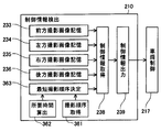
図7Aは、第2実施例による制御情報検出装置の大まかな内部構成を示したブロック図であり、
図7Bは、第2実施例による制御情報検出装置の大まかな内部構成を示したブロック図であり、
図8は、制御情報検出装置が実行する制御情報検出処理のフローチャートであり、
図9は、車線境界推定箇所の照合の様子を示す説明図であり、
図10は、車線境界推定箇所の照合の様子を示す別の説明図であり、
図11は、第2実施例の変形例による制御情報検出装置が実行する最短撮影順序決定処理のフローチャートであり、
図12は、制御情報検出装置によるフィールド画像の読出しが最短撮影順序に該当する場合と該当しない場合の所要時間の違いを示した説明図である。
以下では、制御情報検出装置の実施例について説明する。
(第1実施例)
(第1実施例の装置構成)
図1には、制御情報検出装置10を搭載した車両1の大まかな内部構成が示されている。車両1は、図1に示す通り、制御情報検出装置10と、左前方車載カメラ11と、右前方車載カメラ12と、車両制御部17とを備えている。本実施例の制御情報検出装置10は、左前方車載カメラ11および右前方車載カメラ12が撮影した画像から車両1の走行を制御するための制御情報を検出するための装置である。
(第1実施例)
(第1実施例の装置構成)
図1には、制御情報検出装置10を搭載した車両1の大まかな内部構成が示されている。車両1は、図1に示す通り、制御情報検出装置10と、左前方車載カメラ11と、右前方車載カメラ12と、車両制御部17とを備えている。本実施例の制御情報検出装置10は、左前方車載カメラ11および右前方車載カメラ12が撮影した画像から車両1の走行を制御するための制御情報を検出するための装置である。
左前方車載カメラ11および右前方車載カメラ12は、互いに重複した撮影領域を有し、車両1の前方を所定の周期で撮影するビデオカメラである。そして、左前方車載カメラ11および右前方車載カメラ12は、映像を構成する単位である1フレーム分の静止画像を、走査線毎に飛び越して走査するインターレース方式により、複数本の走査線が間引かれた状態のフィールド画像20に分割して制御情報検出装置10に出力する。フィールド画像20には、以下に説明する奇数フィールド画像21と偶数フィールド画像22とがあり、これらが交互に繰り返して出力される。尚、左前方車載カメラ11および右前方車載カメラ12が本開示の「車載カメラ」に対応する。
図2Aから図2Cには、フィールド画像20の具体例が示されている。図2Bに示す本実施例のフィールド画像20には、偶数列の走査線を間引いて奇数列の走査線を出力する奇数フィールド画像21と、奇数列の走査線を間引いて偶数列の走査線を出力する偶数フィールド画像22とがある。これらを合成すれば、1フレーム分の静止画像である図2Aに記載のフレーム画像23となる。
フィールド画像20の態様は、図2Bに示される場合に限られず、図2Cに示されるような、3n+1列目フィールド画像24と、3n+2列目フィールド画像25と、3n+3列目フィールド画像26(n=0,1,2,3……)といった三つ以上に分割したフィールド画像20を読み出すこととしてもよい。
制御情報検出装置10は、図1に示す通り、左前方車載カメラ11が撮影した画像を記憶する左撮影画像記憶部31と、右前方車載カメラ12が撮影した画像を記憶する右撮影画像記憶部32と、撮影画像を解析して車両1を制御するための制御情報を取得する制御情報取得部38と、制御情報を車両制御部17に出力する制御情報出力部39とを備える。
尚、左撮影画像記憶部31、右撮影画像記憶部32、制御情報取得部38および制御情報出力部39は、制御情報検出装置10の内部が物理的に区分されることを表すのではなく、制御情報検出装置10が果たす機能を分類した概念である。従って、これらの「部」は、CPUで実行されるコンピュータプログラムとして実現することもできるし、LSIやメモリーを含む電子回路として実現することもできるし、これらを組み合わせることによって実現することもできる。
左撮影画像記憶部31は、左前方車載カメラ11の撮影周期に同期して取得した撮影画像であるフィールド画像20を記憶する。上述した通り、左前方車載カメラ11は、奇数フィールド画像21と偶数フィールド画像22とを交互に出力するため、左撮影画像記憶部31も奇数フィールド画像21と偶数フィールド画像22とを交互に記憶することとなる。右撮影画像記憶部32も同様に、右前方車載カメラ12の撮影周期に同期して取得したフィールド画像20を記憶する。
このようにフィールド画像20を記憶した左撮影画像記憶部31および右撮影画像記憶部32は、記憶した複数のフィールド画像20のうち直近のフィールド画像20を読み出し可能な状態で保持する。こうすれば、制御情報取得部38が左撮影画像記憶部31および右撮影画像記憶部32から直近のフィールド画像20を取得できる。このように、左撮影画像記憶部31および右撮影画像記憶部32は、左前方車載カメラ11および右前方車載カメラ12からの出力周期と、制御情報取得部38の処理周期との間に生ずるタイムラグを吸収するためのバッファーメモリーである。
尚、左撮影画像記憶部31、右撮影画像記憶部32が本開示の「撮影画像記憶部」に対応する。
制御情報取得部38は、左撮影画像記憶部31に記憶されたフィールド画像20と、右撮影画像記憶部32に記憶されたフィールド画像20とを解析して車両1を制御するための情報を検出する。解析の観測対象としては、例えば、歩行者、路上障害物、車線、交通標識等が挙げられるが、これらに限られず、車両1の周囲の状況を把握することが可能なあらゆる事物を観測対象とすることができる。
尚、この解析については、一部の走査線が間引かれた状態のフィールド画像20をそのまま解析してもよいし、取得した奇数フィールド画像21または偶数フィールド画像22の画像情報によって奇数列または偶数列いずれかが間引かれた走査線を補間してから解析してもよい。また、解析の対象とするフィールド画像20が奇数フィールド画像21であるか偶数フィールド画像22であるかを同期信号によって判定することにより、奇数列と偶数列とを取り違えることによって生じる誤差を防止するとよい。
制御情報出力部39は、制御情報取得部38によって取得した車両1を制御するための情報を車両制御部17に出力する。
車両制御部17は、制御情報検出装置10が備える制御情報出力部39から出力される制御情報に従って車両1を制御する。ここでいう車両1の制御とは、例えば、車両1を加減速したり、操舵角を変更したりといった運転支援の他、運転者に対して注意や警告を発したりといったことが挙げられ、車両に関する種々の制御が広く含まれる。
(制御情報検出装置の制御情報処理)
ここで、左前方車載カメラ11および右前方車載カメラ12からフィールド画像20を取得し、車両1を制御するための情報を車両制御部17に出力するまでに、制御情報検出装置10の内部で行われる処理について説明する。
(制御情報検出装置の制御情報処理)
ここで、左前方車載カメラ11および右前方車載カメラ12からフィールド画像20を取得し、車両1を制御するための情報を車両制御部17に出力するまでに、制御情報検出装置10の内部で行われる処理について説明する。
図3には、本実施例の制御情報検出装置10が実行する制御情報検出処理のフローチャートが示されている。この制御情報検出処理は、左前方車載カメラ11および右前方車載カメラ12の撮影周期に同期させて実行される処理である。
この制御情報検出処理を開始すると、先ず始めに、左前方車載カメラ11および右前方車載カメラ12からそれぞれ出力されたフィールド画像20を記憶する(S101)。S101の処理は、撮影画像記憶工程に対応する。撮影は連続的に行われるため、記憶されたフィールド画像20が溜まっていくこととなるが、左前方車載カメラ11および右前方車載カメラ12毎に新しく記憶されたフィールド画像20を解析可能な状態としておく。尚、古いフィールド画像20については随時消去してもよいし、保存しておいてもよい。
次に、その記憶した左前方車載カメラ11から出力されたフィールド画像20と、右前方車載カメラ12から出力されたフィールド画像20とを解析して、車両1の制御のための制御情報を取得する(S102)。S102の処理は、制御情報取得工程に対応する。このように解析対象となるのは、フレーム単位ではなく、奇数フィールド画像21または偶数フィールド画像22いずれかのフィールド単位である。
続いて、取得した制御情報を車両制御部17に出力して(S103)、制御情報検出処理は終了する。車両制御部17は、このようにして取得した制御情報を用いて車両1の制御を行うことができる。
以下、左前方カメラおよび右前方カメラの動作と、制御情報検出装置10の動作との関係について、比較例の場合と比較しつつ説明する。
図4には、下方に向かって流れる時間軸をとって、左前方カメラおよび右前方カメラが奇数フィールド画像および偶数フィールド画像を撮影するタイミングと、制御情報検出装置が制御情報を検出するタイミングとが示されている。図示する通り、左前方カメラおよび右前方カメラのそれぞれは奇数フィールド画像または偶数フィールド画像を交互に同じ周期で撮影を繰り返し、制御情報検出装置はカメラの撮影周期と同期して制御情報の検出を繰り返す。そして、この比較例の制御情報検出装置は、一度の制御情報検出のために、左前方カメラから奇数フィールド画像および偶数フィールド画像の両方を読み出し、右前方カメラからも奇数フィールド画像および偶数フィールド画像の両方を読み出している。
図5には、本実施例の場合の、左前方車載カメラ11および右前方車載カメラ12の動作と、制御情報検出装置10の動作との関係が示されている。上記の比較例に対して、本実施例の制御情報検出装置10は、左前方車載カメラ11および右前方車載カメラ12のそれぞれから、偶数フィールド画像22のみを読み出して、走査線が間引かれた状態のままで制御情報を検出している。この際、左前方車載カメラ11および右前方車載カメラ12のそれぞれから出力される奇数フィールド画像21については、制御情報の検出に使用していない。制御情報検出装置10は、その次に制御情報を検出する際にも偶数フィールド画像22のみを読み出す。本実施例の制御情報検出装置10はこのような処理を所定周期で繰り返す。
もっとも、上記の例に限られず、図5の下部に破線で囲った制御情報検出のように、左前方車載カメラ11および右前方車載カメラ12から奇数フィールド画像21のみを読み出してもよい。また、図示は省略するが、撮影周期のずれ方によっては、一方の車載カメラからは奇数フィールド画像21を、他方の車載カメラからは偶数フィールド画像22をそれぞれ読み出すこととしてもよい。
このように、制御情報検出装置10は、左前方車載カメラ11および右前方車載カメラ12のそれぞれにおいて最も新しく撮影されたフィールド画像20を、奇数フィールド画像21であるか偶数フィールド画像22であるかを問わずに読み出す。
図6Aと図6Bには、上記の左前方車載カメラ11および右前方車載カメラ12の動作と、制御情報検出装置10の動作との関係にあって、比較例の場合と本実施例の場合における撮影時刻のずれの大きさの違いが示されている。
図6Aに示される比較例の場合では、最も先に撮影された右前方カメラの奇数フィールド画像の撮影時刻と、最も後に撮影された左前方カメラの偶数フィールド画像の撮影時刻は大きく異なる(図6A右端矢印)。この撮影時刻のずれによって、左前方カメラの偶数フィールド画像は、右前方カメラの奇数フィールド画像を撮影してから、車両が走行した分、異なる位置から撮影されたものとなってしまう。このため、車両の走行速度が十分に小さな場合を撮影の対象とするか、あるいは、この撮影時刻のずれの問題を解消するために、2つの車載カメラの撮影周期を同期させることとしていた。
図6Bに示される本実施例の場合では、右前方車載カメラ12が撮影してから、左前方車載カメラ11が撮影するまでの時間が撮影時刻のずれは、比較例に比べて小さくなっている(図6B右端矢印)。
このように本実施例の制御情報検出装置10では、フィールド画像20の単位を解析対象とし、撮影時刻のずれが小さくなるため、左前方車載カメラ11と右前方車載カメラ12との撮影位置の差を小さくすることができる。これによって、本実施例の制御情報検出装置10は、車両1の走行速度が大きくなっても、左前方車載カメラ11および右前方車載カメラ12の撮影周期を同期させることなく、左前方車載カメラ11および右前方車載カメラ12による撮影画像を解析して情報を取得することが可能となる。
ここで、左前方車載カメラ11および右前方車載カメラ12の撮影周期と、制御情報検出装置10が実行する制御情報検出処理の周期との関係について説明する。制御情報検出処理の周期は、左前方車載カメラ11および右前方車載カメラ12の撮影周期に同期していることは上述した通りである。例えば、左前方車載カメラ11および右前方車載カメラ12がそれぞれ、約33msecごとに奇数フィールド画像21および偶数フィールド画像22を一つずつ出力する場合に、制御情報検出処理は、これと同様に約33msecごとに実行できる。比較例の場合であっても(図4参照)、これと同様の周期で処理することができるが、一度の制御情報検出処理で奇数フィールド画像21および偶数フィールド画像22の両方を使用して処理するため、この撮影周期に対して制御情報検出処理の周期をこれ以上短くすることはできない。
これに対して本実施例によると、同じ撮影周期に対して、約16.6msecごとに制御情報検出処理を実行することもできる。この点について以下に説明する。左前方車載カメラ11および右前方車載カメラ12がそれぞれ、約33msecごとに奇数フィールド画像21および偶数フィールド画像22を一つずつ出力するということは、その半分の約16.6msecごとに奇数フィールド画像21または偶数フィールド画像22のいずれかが交互に出力されるということである。そうすると、本実施例では、奇数フィールド画像21および偶数フィールド画像22のうち、いずれか一方を使用できればよいので、約16.6msecごとに制御情報検出処理を実行すれば、左前方車載カメラ11および右前方車載カメラ12の両方から常に更新された直近のフィールド画像20を読み出して解析処理することができることとなる。
(第2実施例の装置構成)
本実施例では、観測対象が特に車線境界240である場合について説明する。本実施例の制御情報検出装置210でも第1実施例と同様に、奇数フィールド画像221または偶数フィールド画像222を読出して、フィールド画像220の単位で処理する。
(第2実施例の装置構成)
本実施例では、観測対象が特に車線境界240である場合について説明する。本実施例の制御情報検出装置210でも第1実施例と同様に、奇数フィールド画像221または偶数フィールド画像222を読出して、フィールド画像220の単位で処理する。
図7Aと図7Bには、制御情報検出装置210を搭載した車両201の大まかな内部構成が示されている。第1実施例では車両1の前方に左前方車載カメラ11および右前方車載カメラ12の2つの車載カメラが設けられていたが、本実施例では、前方車載カメラ213、左方車載カメラ214、右方車載カメラ215、後方車載カメラ216の4つの車載カメラを設けられている。また、これらに対応して前方撮影画像記憶部233、左方撮影画像記憶部234、右方撮影画像記憶部235、後方撮影画像記憶部236が設けられている。その他の構成は、第1実施例と同様に車両制御部217、車両情報取得部238、制御情報出力部239を備える。
尚、左方車載カメラ214および右方車載カメラ215が本開示の「側方車載カメラ」に対応する。また、前方撮影画像記憶部233、左方撮影画像記憶部234、右方撮影画像記憶部235および後方撮影画像記憶部236が本開示の「撮影画像記憶部」に対応する。
本実施例で対象とする車線境界240とは、車両201と車線との位置関係を把握することが可能な程度に車線の延長方向とほぼ平行に存在する事物である。典型的には、車道中央線や車道外側線等の道路に描かれた白線等が挙げられるが、その他、車線に沿って埋め込まれた道路鋲、車道および歩道等を区分けする境界ブロック、防護柵や防護壁等も車線境界240として検出することができる。
一般に、このような車線境界240を撮影画像から検出する場合は、撮影画像の輝度の分布から撮影された事物のエッジを抽出し、その種々のエッジの中から観測対象である車線境界240を検出することとなる。しかし、道路上には車両の影やアスファルト舗装の境目など、車線境界240と紛らわしい事物が存在するため、これらと車線境界240とを区別して検出することは容易なことではない。
本実施例の制御情報検出装置210は、この車線境界240をより確実に検出するための装置である。以下では、こうしたことを実現するために制御情報検出装置210の内部で行われる処理について詳しく説明する。
(制御情報検出装置の制御情報検出処理)
図8には、本実施例の制御情報検出装置210が実行する制御情報検出処理のフローチャートが示されている。この制御情報検出処理も、第1実施例と同様に、前方車載カメラ213、左方車載カメラ214、右方車載カメラ215、後方車載カメラ216の4つの車載カメラの撮影周期に同期させて実行される処理である。
(制御情報検出装置の制御情報検出処理)
図8には、本実施例の制御情報検出装置210が実行する制御情報検出処理のフローチャートが示されている。この制御情報検出処理も、第1実施例と同様に、前方車載カメラ213、左方車載カメラ214、右方車載カメラ215、後方車載カメラ216の4つの車載カメラの撮影周期に同期させて実行される処理である。
先ず始めに、4つの車載カメラそれぞれから出力されたフィールド画像220を読み出す(S201)。読み出すフィールド画像220は第1実施例と同様に、奇数フィールド画像221であるか偶数フィールド画像222であるかを問わず、いずれかを読み出せばよい。
次に、読み出した4つのフィールド画像220からそれぞれ車線境界推定箇所241を検出する(S202)。車線境界推定箇所241とは、フィールド画像220から車線境界240と判断できるエッジを検出した場合に、車線境界240と推定されるとして検出したものである。
続いて、車線境界推定箇所241を複数のフィールド画像220から検出したか否かを判断する(S203)。車線境界推定箇所241を複数のフィールド画像220から検出しなかった場合には(S203:no)、この制御情報検出処理を終了する。車線境界推定箇所241を複数のフィールド画像220から検出した場合には(S203:yes)、検出した複数の車線境界推定箇所241を互いに照合し(S204)、これらが一致するか否かを判断する(S205)。
図9には、車線境界推定箇所241の照合の様子が示されている。図9では、前方車載カメラ213、左方車載カメラ214、右方車載カメラ215および後方車載カメラ216がそれぞれ撮影したフィールド画像220である前方撮影画像253、左方撮影画像254、右方撮影画像255および後方撮影画像256を、車両201の上方から俯瞰したように変換して配置されている。尚、この俯瞰画像の図示は、説明の便宜のためにすぎず、必ずしもこのように俯瞰画像に変換することを要するものではない。
図9では、前方撮影画像253で車線境界推定箇所241aを検出し、左方撮影画像254で車線境界推定箇所241bを検出し、後方撮影画像256で車線境界推定箇所241cを検出している。これら車線境界推定箇所241a,241b,241cが撮影された時刻は互いに異なるため、車両201が走行した分だけ、これらの位置関係がずれて撮影されている。ここで、左方撮影画像254で検出した車線境界推定箇所241bを前方撮影画像253の領域まで延長して車線境界推定箇所241b´(図9の斜線部)とすると、この車線境界推定箇所241b´と、前方撮影画像253から検出した車線境界推定箇所241aとの位置関係を照合することができる。
車線境界推定箇所241b´と車線境界推定箇所241aとが互いに一致するか否かについては、両者の近似の程度によって判断することとなる。その近似の程度については任意の閾値を設けて判断すればよいが、車線境界推定箇所241b´と車線境界推定箇所241aとが重なり合って検出された場合や、図9のように接触して検出された場合であれば、これらが互いに一致するため、同じ一つの車線境界240を検出したと判断することに特に問題は生じないと考えられる。
一方、図10のように車線境界推定箇所241b´と車線境界推定箇所241aとが少し離れた場所で検出された場合には、これらが同じ一つの車線境界240を検出したのか、車両の影等の車線境界240と似た事物と混同して検出したのか判断することが難しくなる。
この点、本実施例の制御情報検出装置210では、第1実施例と同様に、フィールド画像220の単位で処理することによって、撮影周期のずれの影響を少なくすることができるため、図10に示すような車線境界推定箇所241a,241b,241cの位置ずれ量を小さくすることができる。これによって、車両の影やアスファルト舗装の境目等の車線境界240と紛らわしい事物と混同して検出してしまうことを回避し、車線境界240をより確実に検出することができる。
また、フレーム単位で処理する場合には、異なった撮影時刻による奇数列の走査線と偶数列の走査線とが交互に存在するため、車両の移動に伴って車線境界240が二重に映ってしまうためエッジを検出しにくくなる。これに対して、本実施例のように解析対象をフィールド画像220の単位とすれば、このような二重映りによってエッジを検出しにくくなるといったことをなくすことができる。
以上のようにして、検出した複数の車線境界推定箇所241を互いに照合し(S204)、これらが一致するか否かを判断することができる(S205)。
そして、左方撮影画像254からの検出による車線境界推定箇所241b´と前方撮影画像253から検出した車線境界推定箇所241aとが互いに一致しないと判断した場合(S205:no)、この制御情報検出処理を終了する。
一方、車線境界推定箇所241b´と車線境界推定箇所241aとが互いに一致すると判断した場合(S205:yes)、検出した車線境界240の位置を出力し(S206)、この制御情報検出処理を終了する。
以上に説明した通り、本実施例の制御情報検出装置210は、車両201を制御するための制御情報としてより確実に検出され信頼度の高い車線境界240の位置を出力する。ここにおいて、出力する車線境界240の位置は、車両201の側方に設けられた左方車載カメラ214または右方車載カメラ215から撮影した画像(左方撮影画像254または右方撮影画像255)から検出するとよい。尚、左方撮影画像254または右方撮影画像255は側方撮影画像に対応する。こうすることで、検出対象である車線境界240をより近い位置から撮影することができ、検出によって生じる、車両201に対する車線境界240の位置の誤差を少なくすることができる。また、路面の傾斜や車両201の重量バランスが変化すると、車両201が傾いて車載カメラと車線境界240との位置関係に影響を及ぼすが、車両201の側方に設けられた左方車載カメラ214および右方車載カメラ215が受ける影響は、前方車載カメラ213または後方車載カメラ216が受ける影響よりも比較的小さく済む。
もちろん、前方車載カメラ213または後方車載カメラ216から撮影した画像(前方撮影画像253または後方撮影画像256)から検出した車線境界240の位置を出力することもできる。いずれにしても、車両201の側方の撮影領域および前方(または後方)の撮影領域という互いに異なる広い撮影領域から車線境界240を検出するため、いずれかの車載カメラ単独で検出する場合と比べて、より長い距離の車線境界240を確認できるため、車線境界240でないものを検出してしまうといった誤検出の可能性を減らすことができる。
(第2実施例の変形例)
以上のように第2実施例では、前方車載カメラ213、左方車載カメラ214、右方車載カメラ215および後方車載カメラ216の撮影周期のずれの影響を少なくすることができたが、本変形例では、さらにその撮影周期のずれの影響を少なくする処理について説明する。
(第2実施例の変形例)
以上のように第2実施例では、前方車載カメラ213、左方車載カメラ214、右方車載カメラ215および後方車載カメラ216の撮影周期のずれの影響を少なくすることができたが、本変形例では、さらにその撮影周期のずれの影響を少なくする処理について説明する。
本変形例の制御情報検出装置310は、第2実施例の制御情報検出装置210に対して更に、撮影順序取得部361と、所要時間算出部362と、最短撮影順序決定部363とが追加されている。以下、これらによって実行される最短撮影順序決定処理について、各部の機能に言及しつつ説明する。
図11には、本変形例の制御情報検出装置310が実行する最短撮影順序決定処理のフローチャートが示されている。この最短撮影順序決定処理は、第2実施例で説明した制御情報検出処理に先立って実行される。
最短撮影順序決定処理を開始すると先ず始めに、撮影順序取得部361によって、4つの車載カメラの撮影順序と、車載カメラ間の時間間隔とを取得する(S251)。ここで、4つの車載カメラの撮影順序とは、前方車載カメラ213、左方車載カメラ214、右方車載カメラ215および後方車載カメラ216が、どのような順序で画像を撮影するかを表している。すなわち、これら4つの車載カメラ(前方車載カメラ213、左方車載カメラ214、右方車載カメラ215、後方車載カメラ216)は同じ撮影周期で撮影するが、撮影を開始するタイミングはずれている。従って、前方車載カメラ213、左方車載カメラ214、右方車載カメラ215および後方車載カメラ216は、撮影開始のタイミングによって決まる一定の順序で画像を撮影することになる。
車載カメラの撮影順序とは、このようにして決まる順序を指している。例えば、撮影を開始する順序が、前方車載カメラ213、左方車載カメラ214、右方車載カメラ215、後方車載カメラ216であったとすると、撮影順序は、前方車載カメラ213、左方車載カメラ214、右方車載カメラ215、後方車載カメラ216となる。
尚、撮影順序は循環する(順序の先頭が前方車載カメラ213の場合は、最後も前方車載カメラ213となる)ので、例えば、撮影順序が前方車載カメラ213、左方車載カメラ214、右方車載カメラ215、後方車載カメラ216、前方車載カメラ213である場合と、撮影順序が左方車載カメラ214、右方車載カメラ215、後方車載カメラ216、前方車載カメラ213、左方車載カメラ214とは同じ撮影順序として扱う。
また、4つの車載カメラ間での時間間隔とは、4つの車載カメラがある撮影順序で撮影する時に隣り合う順序の車載カメラ間での撮影の時間間隔を指す。従って、上記の撮影順序が前方車載カメラ213、左方車載カメラ214、右方車載カメラ215、後方車載カメラ216、前方車載カメラ213である場合にあっては、以下の時間間隔を取得することとなる。すなわち、前方車載カメラ213および左方車載カメラ214、左方車載カメラ214および右方車載カメラ215、右方車載カメラ215および後方車載カメラ216、後方車載カメラ216および前方車載カメラ213の4つの時間間隔である。
次に、所要時間算出部362が、4つの車載カメラから1つの車載カメラを選択し(S252)、選択した車載カメラが撮影してから他の全ての車載カメラが撮影するまでに要する所要時間を算出する(S253)。この所要時間は、上記の処理(S251)によって取得した4つの車載カメラ間の時間間隔を用いれば容易に算出することができる。
そして、全ての車載カメラについて所要時間を算出したか否かを判断し(S254)、未だの場合は(S254:no)、1つの車載カメラを選択する処理に戻って繰り返す。このように、所要時間を算出する処理は、全ての車載カメラのそれぞれについて実行される。従って、本変形例のように4つの車載カメラを用いている場合は、4通りの所要時間が算出されることとなる。
全ての車載カメラについて所要時間を算出したら(S254:yes)、最短撮影順序決定部363が、所要時間が最短となる最短撮影順序を決定する(S255)。この最短撮影順序を決定する処理は、上記の処理によって算出された4通りの所要時間の中から最短の場合を選ぶことにより実行される。
こうして、最短撮影順序を決定すると(S255)、この最短撮影順序決定処理は終了する。そして、第2実施例と同様に制御情報検出処理が実行されるが、その際、制御情報取得部238による4つのフィールド画像220の読出し(S201)については(図8参照)、上記で決定された最短撮影順序に従うこととなる。つまり、制御情報取得部238は、車載カメラ毎に読み出された直近のフィールド画像220が取得された順番が、最短撮影順序となるタイミングで、車載カメラ毎のフィールド画像220を読み出すこととなる。
図12には、最短撮影順序に該当する場合と該当しない場合の所要時間の違いが示されている。制御情報検出装置310が行う制御情報検出のうち、上側の検出タイミングCが最短撮影順序に該当しない場合の例示である。このときの所要時間は、前方車載カメラ213が撮影してから後方車載カメラ216が撮影するまでに要する時間であって、ε1である。この場合であっても、第2実施例の制御情報検出処理には該当しているため、比較例と比べれば、4つの車載カメラ間の撮影周期のずれの影響は少なくなっている。
これに対して、検出タイミングDが最短撮影順序に従う場合の例示である。このときの所要時間は、左方車載カメラ214が撮影してから前方車載カメラ213が撮影するまでに要する時間であって、ε2である。上記のε1とこのε2とを見比べれば、第2実施例によって少なくなった撮影周期のずれの影響が、本変形例の最短撮影順序決定処理を実行することによって、さらに少なくなることがわかる。
本開示の一態様の制御情報検出装置および制御情報検出方法は、複数の車載カメラからフィールド画像の単位で出力される撮影画像を、車載カメラ毎に記憶しておき、複数の車載カメラの撮影画像を解析して、車両の走行を制御するための制御情報を検出する。ここで、複数の車載カメラの撮影画像を解析するに際しては、車載カメラ毎に直近に取得されたフィールド画像を解析する。
車載カメラからはインターレース方式でフィールド画像が出力されるので、フィールド画像によって撮影画像を完成させるためには、車載カメラが複数の撮影画像を撮影する必要が生じ、その間に車両が長い距離を移動する事態も発生し得る。これに対して、本開示の制御情報検出装置および制御情報検出方法では、各車載カメラからは直近のフィールド画像を取得すればよいので、車載カメラが複数の撮影画像を撮影する必要はない。このため、複数の車載カメラが撮影画像を撮影する間に、車両が長い距離を移動する事態を回避することができる。その結果、たとえ複数の車載カメラの撮影タイミングが同期していない場合でも、複数の車載カメラの撮影画像から情報を引き出すことが可能となる。
この出願に記載されるフローチャート、あるいは、フローチャートの処理は、複数のステップ(あるいはセクションと言及される)から構成され、各ステップは、たとえば、S101と表現される。さらに、各ステップは、複数のサブステップに分割されることができる、一方、複数のステップが合わさって一つのステップにすることも可能である。
以上、本開示に係る制御情報検出装置および制御情報検出方法の実施形態、構成、態様を例示したが、本開示に係る実施形態、構成、態様は、上述した各実施形態、各構成、各態様に限定されるものではない。例えば、異なる実施形態、構成、態様にそれぞれ開示された技術的部を適宜組み合わせて得られる実施形態、構成、態様についても本開示に係る実施形態、構成、態様の範囲に含まれる。
Claims (4)
- 所定の撮影周期で撮影した撮影画像をインターレース方式で複数のフィールド画像(20)に分けた後に出力する車載カメラ(11,12)を、複数備える車両(1)に搭載されて、該複数の車載カメラから取得した前記撮影画像を解析することにより、該車両の走行を制御するための制御情報を検出する制御情報検出装置であって、
前記複数の車載カメラの各々について、該車載カメラが前記撮影画像を撮影する度に前記フィールド画像の単位で出力する該撮影画像を取得して、前記複数の車載カメラ毎に記憶する撮影画像記憶部(31,32)と、
前記車載カメラ毎に記憶された複数の前記撮影画像を解析して、前記制御情報を取得する制御情報取得部(38)と
を備え、
前記撮影画像記憶部は、前記撮影画像を、前記フィールド画像の単位で読み出し可能な状態で記憶し、
前記制御情報取得部は、前記車載カメラ毎に直近に取得された前記フィールド画像を前記撮影画像記憶部から読み出して、前記撮影画像として解析することにより、前記制御情報を取得する
制御情報検出装置。 - 請求項1に記載の制御情報検出装置であって、
前記撮影画像記憶部は、前記車両から前方を撮影する前方車載カメラ(213)による前方撮影画像(253)と、該車両から側方を撮影する側方車載カメラ(214,215)による側方撮影画像(254,255)とを含む前記複数の撮影画像を記憶し、
前記制御情報取得部は、前記前方撮影画像および前記側方撮影画像を含む前記複数の撮影画像を解析して、前記車両が走行する車線の位置を取得する
制御情報検出装置。 - 請求項1または請求項2に記載の制御情報検出装置であって、
前記複数の車載カメラが前記撮影画像を撮影する撮影順序と、前記車載カメラが撮影してから次の前記車載カメラが撮影するまでの時間間隔とを取得する撮影順序取得部(361)と、
前記複数の車載カメラの各々について、該車載カメラが撮影してから他の全ての前記車載カメラが撮影するまでに要する所要時間を、前記撮影順序取得部に記憶されている前記車載カメラ間での前記時間間隔に基づいて算出する所要時間算出部(362)と、
前記所要時間算出部によって算出された前記所要時間が最短となる最短撮影順序を決定する最短撮影順序決定部(363)と
を備え、
前記制御情報取得部は、前記車載カメラ毎に読み出された前記直近のフィールド画像が取得された順番が、前記最短撮影順序となるタイミングで、該車載カメラ毎の該フィールド画像を読み出す
制御情報検出装置。 - 所定の撮影周期で撮影した撮影画像をインターレース方式で複数のフィールド画像に分けた後に出力する車載カメラを、複数備える車両に適用されて、該複数の車載カメラから取得した前記撮影画像を解析することにより、該車両の走行を制御するための制御情報を検出する制御情報検出方法であって、
前記複数の車載カメラの各々について、該車載カメラが前記撮影画像を撮影する度に前記フィールド画像の単位で出力する該撮影画像を取得して、前記複数の車載カメラ毎に記憶する撮影画像記憶工程(S101)と、
前記車載カメラ毎に記憶された複数の前記撮影画像を解析して、前記制御情報を取得する制御情報取得工程(S102)と
を備え、
前記撮影画像記憶工程は、前記撮影画像を、前記フィールド画像の単位で読み出し可能な状態で記憶し、
前記制御情報取得工程は、前記車載カメラ毎に直近に取得された前記フィールド画像を読み出して、前記撮影画像として解析することにより、前記制御情報を取得する
制御情報検出方法。
Applications Claiming Priority (2)
| Application Number | Priority Date | Filing Date | Title |
|---|---|---|---|
| JP2014154628A JP6277904B2 (ja) | 2014-07-30 | 2014-07-30 | 制御情報検出装置および制御情報検出方法 |
| JP2014-154628 | 2014-07-30 |
Publications (1)
| Publication Number | Publication Date |
|---|---|
| WO2016017136A1 true WO2016017136A1 (ja) | 2016-02-04 |
Family
ID=55217054
Family Applications (1)
| Application Number | Title | Priority Date | Filing Date |
|---|---|---|---|
| PCT/JP2015/003739 Ceased WO2016017136A1 (ja) | 2014-07-30 | 2015-07-27 | 制御情報検出装置および制御情報検出方法 |
Country Status (2)
| Country | Link |
|---|---|
| JP (1) | JP6277904B2 (ja) |
| WO (1) | WO2016017136A1 (ja) |
Families Citing this family (1)
| Publication number | Priority date | Publication date | Assignee | Title |
|---|---|---|---|---|
| JP7490483B2 (ja) * | 2020-07-22 | 2024-05-27 | キヤノン株式会社 | システム、情報処理方法、物品の製造方法、プログラム及び記録媒体 |
Citations (3)
| Publication number | Priority date | Publication date | Assignee | Title |
|---|---|---|---|---|
| JP2002027448A (ja) * | 2000-04-28 | 2002-01-25 | Matsushita Electric Ind Co Ltd | 画像処理装置および監視システム |
| JP2008250904A (ja) * | 2007-03-30 | 2008-10-16 | Toyota Motor Corp | 車線区分線情報検出装置、走行車線維持装置、車線区分線認識方法 |
| JP2012185304A (ja) * | 2011-03-04 | 2012-09-27 | Nikon Corp | 画像表示装置および顕微鏡システム |
-
2014
- 2014-07-30 JP JP2014154628A patent/JP6277904B2/ja active Active
-
2015
- 2015-07-27 WO PCT/JP2015/003739 patent/WO2016017136A1/ja not_active Ceased
Patent Citations (3)
| Publication number | Priority date | Publication date | Assignee | Title |
|---|---|---|---|---|
| JP2002027448A (ja) * | 2000-04-28 | 2002-01-25 | Matsushita Electric Ind Co Ltd | 画像処理装置および監視システム |
| JP2008250904A (ja) * | 2007-03-30 | 2008-10-16 | Toyota Motor Corp | 車線区分線情報検出装置、走行車線維持装置、車線区分線認識方法 |
| JP2012185304A (ja) * | 2011-03-04 | 2012-09-27 | Nikon Corp | 画像表示装置および顕微鏡システム |
Also Published As
| Publication number | Publication date |
|---|---|
| JP2016031701A (ja) | 2016-03-07 |
| JP6277904B2 (ja) | 2018-02-14 |
Similar Documents
| Publication | Publication Date | Title |
|---|---|---|
| JP6045888B2 (ja) | 車載画像処理装置 | |
| JP4801821B2 (ja) | 道路形状推定装置 | |
| RU2634852C1 (ru) | Устройство обнаружения светофора и способ обнаружения светофора | |
| EP2927054B1 (en) | On-vehicle control device | |
| JP6649738B2 (ja) | 駐車区画認識装置、駐車区画認識方法 | |
| JP6586849B2 (ja) | 情報表示装置及び情報表示方法 | |
| JP6642906B2 (ja) | 駐車位置検出システム及びそれを用いた自動駐車システム | |
| JP7255345B2 (ja) | 走行車線認識装置、走行車線認識方法およびプログラム | |
| CN105868688A (zh) | 行驶路面检测装置和行驶路面检测方法 | |
| CN104335264A (zh) | 车道划分标示检测装置、驾驶辅助系统 | |
| CN110088801B (zh) | 可行驶区域检测装置以及行驶辅助系统 | |
| JP6154213B2 (ja) | 路面情報取得装置 | |
| CN106056569A (zh) | 行驶路面检测装置和行驶路面检测方法 | |
| CN107924569A (zh) | 图像处理装置和图像处理方法 | |
| KR20200028679A (ko) | 차선을 검출하는 방법 및 장치 | |
| JP6086424B2 (ja) | 車載画像処理装置 | |
| JP2014106739A (ja) | 車載画像処理装置 | |
| JP6152261B2 (ja) | 車載用駐車枠認識装置 | |
| WO2015133072A1 (ja) | 車両周辺画像表示装置、車両周辺画像表示方法 | |
| JP6032141B2 (ja) | 走行路面標示検知装置および走行路面標示検知方法 | |
| JP2006309313A (ja) | 道路認識装置 | |
| US20150379372A1 (en) | Object recognition apparatus | |
| JP5832850B2 (ja) | 車線監視システム及び車線監視方法 | |
| JP6148848B2 (ja) | 車載画像処理装置 | |
| JP2019053685A (ja) | 画像処理装置 |
Legal Events
| Date | Code | Title | Description |
|---|---|---|---|
| 121 | Ep: the epo has been informed by wipo that ep was designated in this application |
Ref document number: 15827376 Country of ref document: EP Kind code of ref document: A1 |
|
| NENP | Non-entry into the national phase |
Ref country code: DE |
|
| 122 | Ep: pct application non-entry in european phase |
Ref document number: 15827376 Country of ref document: EP Kind code of ref document: A1 |