WO2016017020A1 - 光情報記録再生方法、光情報記録再生装置 - Google Patents
光情報記録再生方法、光情報記録再生装置 Download PDFInfo
- Publication number
- WO2016017020A1 WO2016017020A1 PCT/JP2014/070297 JP2014070297W WO2016017020A1 WO 2016017020 A1 WO2016017020 A1 WO 2016017020A1 JP 2014070297 W JP2014070297 W JP 2014070297W WO 2016017020 A1 WO2016017020 A1 WO 2016017020A1
- Authority
- WO
- WIPO (PCT)
- Prior art keywords
- information recording
- optical information
- hologram
- light
- reference light
- Prior art date
- Legal status (The legal status is an assumption and is not a legal conclusion. Google has not performed a legal analysis and makes no representation as to the accuracy of the status listed.)
- Ceased
Links
Images







Classifications
-
- G—PHYSICS
- G03—PHOTOGRAPHY; CINEMATOGRAPHY; ANALOGOUS TECHNIQUES USING WAVES OTHER THAN OPTICAL WAVES; ELECTROGRAPHY; HOLOGRAPHY
- G03H—HOLOGRAPHIC PROCESSES OR APPARATUS
- G03H1/00—Holographic processes or apparatus using light, infrared or ultraviolet waves for obtaining holograms or for obtaining an image from them; Details peculiar thereto
- G03H1/04—Processes or apparatus for producing holograms
-
- G—PHYSICS
- G03—PHOTOGRAPHY; CINEMATOGRAPHY; ANALOGOUS TECHNIQUES USING WAVES OTHER THAN OPTICAL WAVES; ELECTROGRAPHY; HOLOGRAPHY
- G03H—HOLOGRAPHIC PROCESSES OR APPARATUS
- G03H1/00—Holographic processes or apparatus using light, infrared or ultraviolet waves for obtaining holograms or for obtaining an image from them; Details peculiar thereto
- G03H1/26—Processes or apparatus specially adapted to produce multiple sub- holograms or to obtain images from them, e.g. multicolour technique
- G03H1/30—Processes or apparatus specially adapted to produce multiple sub- holograms or to obtain images from them, e.g. multicolour technique discrete holograms only
-
- G—PHYSICS
- G11—INFORMATION STORAGE
- G11B—INFORMATION STORAGE BASED ON RELATIVE MOVEMENT BETWEEN RECORD CARRIER AND TRANSDUCER
- G11B7/00—Recording or reproducing by optical means, e.g. recording using a thermal beam of optical radiation by modifying optical properties or the physical structure, reproducing using an optical beam at lower power by sensing optical properties; Record carriers therefor
- G11B7/004—Recording, reproducing or erasing methods; Read, write or erase circuits therefor
- G11B7/0065—Recording, reproducing or erasing by using optical interference patterns, e.g. holograms
-
- G—PHYSICS
- G11—INFORMATION STORAGE
- G11B—INFORMATION STORAGE BASED ON RELATIVE MOVEMENT BETWEEN RECORD CARRIER AND TRANSDUCER
- G11B7/00—Recording or reproducing by optical means, e.g. recording using a thermal beam of optical radiation by modifying optical properties or the physical structure, reproducing using an optical beam at lower power by sensing optical properties; Record carriers therefor
- G11B7/12—Heads, e.g. forming of the optical beam spot or modulation of the optical beam
- G11B7/135—Means for guiding the beam from the source to the record carrier or from the record carrier to the detector
Definitions
- the present invention relates to an optical information recording / reproducing method and an optical information recording / reproducing apparatus for recording information on an optical information recording medium using an interference pattern of signal light and reference light as page data and reproducing information from the optical information recording medium.
- Patent Document 1 Japanese Patent Application Laid-Open No. 2007-293309
- the problem is that "the recording area is partially overlapped to increase the recording density of the optical information, and the adjacent reproduction light reproduced in the area adjacent to the selected recording area is used as the servo control light.
- the structure of the apparatus is simplified, and the angle out of the limit angle is changed to an angle within the limit angle range, and the reference light is irradiated to increase the storage efficiency of the optical information storage medium.
- the optical information processing apparatus, the optical information servo control method, the optical information recording method, and the optical information reproducing method according to the present invention are configured to output optical information at a multiplexing angle having a different offset angle for each track when optical information is recorded. Multiplex recording and reproduction, and the multiplexing angle outside the limit angle is changed to an angle within the limit angle range, and multiple recording and reproduction are performed, and servo control is performed using reproduction light of different tracks that are reproduced together. . Has been described as ".
- WO2009 / 054044 states that “the hologram recording device provided by the present invention uses an objective lens> for recording light modulated according to information to be recorded by a spatial light modulator.
- the objective lens is A lens that converges both the on-axis light beam and the off-axis light beam while converging the recording light as a whole.
- the recording light is converged so as to form a beam waist
- the irradiation position displacing means includes the recording light and the recording light so that portions corresponding to the beam waist in the recording area overlap in adjacent recording areas.
- the irradiation position of the reference light is displaced. ”
- Patent Document 1 In holographic recording technology, in order to increase the recording capacity with a recording medium of a finite size, it is necessary to achieve high density by recording the holograms close to each other.
- the reference light In the technique described in Patent Document 1, when recording holograms close to each other, the reference light is incident at different offset angles for each track, thereby reducing the amount of reproduction light emitted from adjacent holograms during reproduction.
- the configuration of Patent Document 1 separates the reproduction light of the selected hologram and the reproduction light of the adjacent hologram with a filter, the holograms are separated from each other on the beam waist surface most narrowed down on the recording medium. Yes. Therefore, there is a problem that it is disadvantageous from the viewpoint of increasing the capacity.
- Patent Document 2 is disadvantageous from the viewpoint of increasing the capacity because the holograms are formed separately on the beam waist surface.
- Patent Document 3 In the technique described in Patent Document 3, recording is performed so that adjacent holograms overlap at the beam waist by using an objective lens that converges signal light both on and off the axis.
- the configuration of Patent Document 3 has a problem that the signal performance is likely to be deteriorated because the sensitivity to the relative positional deviation between the medium and the optical system is high.
- the present invention has been made in view of the above problems, and in an optical information recording / reproducing apparatus using a hologram, an optical information recording / reproducing method and an optical information recording / reproducing method capable of increasing the recording capacity with a simple configuration.
- An object is to provide an apparatus.
- the above problem is solved by, for example, the invention described in the scope of claims.
- the present application includes a plurality of means for solving the above-mentioned problems.
- the beam waists of signal lights in adjacent holograms overlap each other on the beam waist surface by a predetermined amount, and the adjacent holograms The incident angles of the reference light are shifted from each other by a predetermined amount.
- an optical information recording / reproducing apparatus and an optical information recording / reproducing apparatus capable of increasing the recording capacity with a simple configuration in an optical information recording / reproducing apparatus using a hologram can be provided.
- Schematic diagram showing an embodiment of an optical information recording / reproducing apparatus Schematic showing an example of the recording principle of a pickup in an optical information recording / reproducing apparatus
- Schematic showing an example of the reproduction principle of a pickup in an optical information recording / reproducing apparatus Schematic showing the operation flow from the insertion of the optical information recording medium of the optical information recording / reproducing apparatus to the completion of preparation for recording or reproduction
- Schematic showing the overlap of signal light and reference light incident on an optical information recording medium Schematic diagram showing the positional relationship of a book recorded by a conventional optical information recording / reproducing apparatus and the progress of reproduction light when reproducing the book Schematic showing the positional relationship of the book recorded with the optical information recording / reproducing apparatus in a present Example.
- Schematic representing a hologram formed by a pixel of a spatial light modulator entering an optical information recording medium Schematic showing the relationship between the incident angle of signal light and reference light in an optical information recording medium
- Schematic diagram showing in detail the positional relationship of books recorded by the optical information recording / reproducing apparatus in the present embodiment Schematic showing the hologram recording method in a present
- Example Schematic showing progress of reproduction light when reproducing a book with the optical information recording / reproducing apparatus of the present embodiment
- Schematic showing a recording method for recording one book with a predetermined amount shifted by page so as to suppress consumption of the M number Schematic showing the flow which records information on the optical information recording medium of the optical information recording / reproducing apparatus in a present
- Example Schematic showing the flow which records information on the optical information recording medium of the optical information recording
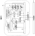
- FIG. 1 is a block diagram showing a recording / reproducing apparatus of an optical information recording medium for recording and / or reproducing digital information using holography.
- the optical information recording / reproducing device 10 is connected to an external control device 91 via an input / output control circuit 90.
- the optical information recording / reproducing apparatus 10 receives the information signal to be recorded from the external control device 91 by the input / output control circuit 90.
- the optical information recording / reproducing apparatus 10 transmits the reproduced information signal to the external control apparatus 91 by the input / output control circuit 90.
- the optical information recording / reproducing apparatus 10 includes a pickup 11, a reproduction reference light optical system 12, a cure optical system 13, a disk rotation angle detection optical system 14, and a rotation motor 50.
- the optical information recording medium 1 is a rotation motor. 50 can be rotated.
- the pickup 11 plays a role of irradiating the optical information recording medium 1 with reference light and signal light and recording digital information on the recording medium using holography.
- the information signal to be recorded is sent by the controller 89 to the spatial light modulator in the pickup 11 via the signal generation circuit 86, and the signal light is modulated by the spatial light modulator.
- the reproduction reference light optical system 12 When reproducing the information recorded on the optical information recording medium 1, the reproduction reference light optical system 12 generates a light wave that causes the reference light emitted from the pickup 11 to enter the optical information recording medium in a direction opposite to that during recording. Generate. Reproduction light reproduced by the reproduction reference light is detected by a photodetector (to be described later) in the pickup 11, and a signal is reproduced by the signal processing circuit 85.
- the irradiation time of the reference light and the signal light applied to the optical information recording medium 1 can be adjusted by controlling the opening / closing time of the shutter in the pickup 11 via the shutter control circuit 87 by the controller 89.
- the cure optical system 13 plays a role of generating a light beam used for pre-cure and post-cure of the optical information recording medium 1.
- Precure is a pre-process for irradiating a predetermined light beam in advance before irradiating the desired position with reference light and signal light when recording information at a desired position in the optical information recording medium 1.
- Post-cure is a post-process for irradiating a predetermined light beam after recording information at a desired position in the optical information recording medium 1 so that additional recording cannot be performed at the desired position.
- the disk rotation angle detection optical system 14 is used to detect the rotation angle of the optical information recording medium 1.
- a signal corresponding to the rotation angle is detected by the disk rotation angle detection optical system 14, and a disk rotation motor control circuit is detected by the controller 89 using the detected signal.
- the rotation angle of the optical information recording medium 1 can be controlled via 88.
- a predetermined light source driving current is supplied from the light source driving circuit 82 to the light sources in the pickup 11, the cure optical system 13, and the disk rotation angle detection optical system 14, and each light source emits a light beam with a predetermined light amount. Can do.
- the pickup 11 and the disc cure optical system 13 are provided with a mechanism capable of sliding the position in the radial direction of the optical information recording medium 1, and the position is controlled via the access control circuit 81.
- the recording technology using the principle of angle multiplexing of holography tends to have a very small tolerance for the deviation of the reference beam angle.
- a mechanism for detecting the deviation amount of the reference beam angle is provided in the pickup 11, a servo control signal is generated by the servo signal generation circuit 83, and the deviation amount is corrected via the servo control circuit 84. It is necessary to provide a servo mechanism for this purpose in the optical information recording / reproducing apparatus 10.
- the pickup 11, the cure optical system 13, and the disk rotation angle detection optical system 14 may be simplified by combining several optical system configurations or all optical system configurations into one.
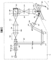
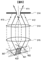
- FIG. 2 shows a recording principle in an example of a basic optical system configuration of the pickup 11 in the optical information recording / reproducing apparatus 10.
- the light beam emitted from the light source 301 passes through the collimator lens 302 and enters the shutter 303.
- the shutter 303 When the shutter 303 is open, after the light beam passes through the shutter 303, the optical ratio of the p-polarized light and the s-polarized light becomes a desired ratio by the optical element 304 composed of, for example, a half-wave plate.
- the optical element 304 composed of, for example, a half-wave plate.
- the light is incident on a PBS (Polarization Beam Splitter) prism 305.
- PBS Polarization Beam Splitter
- the light beam that has passed through the PBS prism 305 functions as signal light 306, and after the light beam diameter is expanded by the beam expander 308, the light beam passes through the phase mask 309, the relay lens 310, and the PBS prism 311 and passes through the spatial light modulator 312. Is incident on.
- the signal light to which information is added by the spatial light modulator 312 reflects the PBS prism 311 and propagates through the relay lens 313 and the spatial filter 314. Thereafter, the signal light is condensed on the optical information recording medium 1 by the objective lens 315.
- the light beam reflected from the PBS prism 305 functions as reference light 307 and is set to a predetermined polarization direction according to recording or reproduction by the polarization direction conversion element 316 and then galvano- lated via the mirror 317 and the mirror 318. Incident on the mirror 319. Since the angle of the galvanometer mirror 319 can be adjusted by the actuator 320, the incident angle of the reference light incident on the optical information recording medium 1 after passing through the lens 321 and the lens 322 can be set to a desired angle. In order to set the incident angle of the reference light, an element that converts the wavefront of the reference light may be used instead of the galvanometer mirror.
- the signal light and the reference light are incident on the optical information recording medium 1 so as to overlap each other, whereby an interference fringe pattern is formed in the recording medium, and information is recorded by writing this pattern on the recording medium.
- the incident angle of the reference light incident on the optical information recording medium 1 can be changed by the galvanometer mirror 319, recording by angle multiplexing is possible.
- holograms corresponding to each reference beam angle are called pages, and a set of pages angle-multiplexed in the same area is called a book. .
- FIG. 3 shows a reproduction principle in an example of a basic optical system configuration of the pickup 11 in the optical information recording / reproducing apparatus 10.
- the reference light is incident on the optical information recording medium 1 as described above, and the light beam transmitted through the optical information recording medium 1 is reflected by the galvanometer mirror 324 whose angle can be adjusted by the actuator 323. By doing so, the reproduction reference light is generated.
- the reproduction light reproduced by the reproduction reference light propagates through the objective lens 315, the relay lens 313, and the spatial filter 314. Thereafter, the reproduction light passes through the PBS prism 311 and enters the photodetector 325, and the recorded signal can be reproduced.
- the photodetector 325 for example, an image sensor such as a CMOS image sensor or a CCD image sensor can be used. However, any element may be used as long as page data can be reproduced.
- the pickup of the present embodiment has been described with the configuration of FIGS. 2 and 3 as an example, but needless to say, it is not limited to this configuration.
- FIG. 4 shows an operation flow of recording and reproduction in the optical information recording / reproducing apparatus 10.
- a flow relating to recording / reproduction using holography in particular will be described.
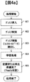
- FIG. 4A shows an operation flow from the insertion of the optical information recording medium 1 into the optical information recording / reproducing apparatus 10 until the preparation for recording or reproduction is completed.
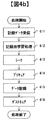
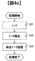
- FIG. FIG. 4C shows an operation flow until information is recorded on the information recording medium 1, and
- FIG. 4C shows an operation flow until the information recorded on the optical information recording medium 1 is reproduced from the ready state.
- the optical information recording / reproducing apparatus 10 discriminates whether the inserted medium is a medium for recording or reproducing digital information using holography, for example. (602).
- the optical information recording / reproducing apparatus 10 reads control data provided on the optical information recording medium (603). ), For example, information relating to the optical information recording medium and information relating to various setting conditions during recording and reproduction, for example.
- the operation flow from the ready state to recording information is as follows. First, data to be recorded is received (611), and information corresponding to the data is received from the spatial light modulator in the pickup 11. Send to.
- the access control circuit 81 is controlled to position the pickup 11 and the cure optical system 13 at predetermined positions on the optical information recording medium.
- the optical information recording medium 1 has address information, it reproduces the address information, checks whether it is positioned at the target position, and calculates the amount of deviation from the predetermined position if it is not positioned at the target position. And repeat the positioning operation.
- a predetermined region is pre-cured using the light beam emitted from the cure optical system 13 (614), and data is recorded using the reference light and signal light emitted from the pickup 11 (615).
- post cure is performed using the light beam emitted from the cure optical system 13 (616). Data may be verified as necessary.
- the operation flow from the ready state to the reproduction of recorded information is as follows.
- the access control circuit 81 is controlled, and the pickup 11 and the reproduction reference light are reproduced.
- the position of the optical system 12 is positioned at a predetermined position on the optical information recording medium.
- the optical information recording medium 1 has address information, it reproduces the address information, checks whether it is positioned at the target position, and calculates the amount of deviation from the predetermined position if it is not positioned at the target position. And repeat the positioning operation.
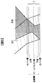
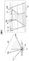
- FIG. 5 shows an overlap relationship between the signal light 306 and the reference light 307 incident on the optical information recording medium 1 in the optical information recording / reproducing apparatus 10.
- the shaded vertical lines indicate the signal light 306, and the shaded dotted lines indicate the reference light 307.
- the optical information recording medium 1 includes a recording layer and a cover layer covering the recording layer.
- the recording layer includes an upper surface, a lower surface, and a beam waist surface on which the signal light 306 is most focused in the middle between the upper surface and the lower surface.
- the signal light 306 becomes convergent light by the objective lens 315 and enters the optical information recording medium 1, and is most narrowed on the beam waist surface as shown in the figure. This state is generally called a beam waist.
- the reference light 307 enters the optical information recording medium 1 as parallel light.
- a hologram is recorded by generating a refractive index modulation in the recording layer by the interference pattern generated by the superposition of the two lights. Note that the signal light and the reference light are preferably incident on the optical information recording medium 1 with a predetermined amount of inclination as shown in the drawing in order to increase the number of multiplexed signals and increase the recording capacity.
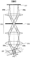
- FIG. 6 shows the positional relationship of the book recorded on the optical information recording medium 1 by the conventional optical information recording / reproducing apparatus, and the state of the signal light traveling to the spatial filter 314 when the recorded selected book 401 is reproduced. .
- a model in which the adjacent book 402 and the adjacent book 403 are formed on both sides on the basis of the selected book 401 recorded in multiple recording is assumed.
- adjacent books 402 and 403 overlap the selected book 401 on the upper and lower surfaces of the recording layer, but on the beam waist surface where the signal light 306 is most focused, The adjacent books 402 to 403 are recorded so as not to overlap each other.
- the reference light 307 is irradiated to the selected book 401 of the optical information recording medium 1, but since the irradiation area is larger by a predetermined amount than the selected book 401 to be reproduced, the adjacent book 402 and the adjacent book 403 also The diffracted signal light travels to the objective lens 315.
- the signal light diffracted by the selected book 401 is denoted by 411
- the signal light diffracted by the adjacent book 402 is denoted by 412
- the signal light diffracted by the adjacent book 403 is denoted by 413.
- the beam waist surface of the optical information recording medium 1 and the spatial filter 314 are arranged so as to form an image with each other by the objective lens 315 and the relay lens 313. That is, the signal lights 411 to 413 are beam waists even on the spatial filter 314.
- the size of the spatial filter 314 so that only the diffracted signal light 411 passes through the selected book 401, the signal light 412 diffracted from the adjacent book 402 and the signal diffracted from the adjacent book 403 as shown in FIG.
- the light 413 can be shielded and physically separated, and a reproduced signal with less noise can be obtained.
- FIG. 7 shows the positional relationship between the selected book 401, the adjacent book 402, and the adjacent book 403 recorded on the optical information recording medium 1 by the optical information recording / reproducing apparatus of the present embodiment.
- the selected book 401 is recorded so as to actively overlap the adjacent book 402 and the adjacent book 403 even on the beam waist surface where the signal light becomes the beam waist. To do. In this way, the recording capacity can be increased by overlapping the books on the beam waist surface.
- FIG. 8 is a schematic diagram showing a hologram formed by the pixels of the spatial light modulator 312 entering the optical information recording medium 1.
- the PBS prism 311 shown in FIG. 2 is omitted, and the spatial light modulator 312 is arranged in a straight line with respect to the relay lens 313.
- the spatial light modulator 312 In the optical information recording / reproducing apparatus 10 of this embodiment, information is added to each pixel by the spatial light modulator 312.
- the signal light emitted from each pixel of the spatial light modulator 312 propagates at a divergence angle passing through the spatial filter 314, and after passing through the objective lens 315, becomes substantially parallel light for each pixel and optical information at a predetermined angle. It can be considered to be incident on the recording medium 1.
- the signal light of the pixel having the smallest angle with the reference light 307 on the optical information recording medium 1 is 306a, and the signal of the pixel with the largest angle with the reference light 307 on the optical information recording medium 1 Let 306b be the light.
- the size of the beam waist formed on the beam waist surface is different between the signal light 306a and the signal light 306b.
- the beam waist size formed by the signal light 306a on the beam waist surface of the optical information recording medium 1 is ⁇ a
- the beam waist size formed by the signal light 306b on the beam waist surface of the optical information recording medium 1 is ⁇ b.
- ⁇ b having a shallow incident angle is larger than ⁇ a.
- the signal light 306a of the pixel having the smallest angle with the reference light 307 is referred to as the innermost signal light
- the signal light 306b of the pixel having the largest angle with the reference light 307 is referred to as the outermost signal light.
- the signal light of each pixel emitted from the spatial light modulator 312 travels on the spatial filter 314 with the same beam waist size. However, since the optical information recording medium 1 and the optical axis are inclined by a predetermined amount, a difference occurs in the beam waist size on the beam waist surface of the optical information recording medium 1 depending on each pixel.
- the beam diameter of the signal light on the beam waist surface is determined by the beam waist size of the outermost signal light. Further, the beam waist size of the signal light incident at other angles is irradiated onto the beam waist surface with a smaller size.
- FIG. 9 is a diagram showing the relationship between the incident angles of the signal light 306 and the reference light 307 in the optical information recording medium 1.
- FIG. 9A shows simplified signal light 306 and reference light 307 incident on the optical information recording medium 1. From the figure, it can be seen that, among the signal light 306, the innermost signal light 306a and the outermost signal light 306b are greatly different in angle with the reference light 307. This is because the signal light 306 is collected by the objective lens 315, and therefore the incident angle to the optical information recording medium 1 varies greatly depending on the position that has passed through the objective lens 315.
- FIG. 9B shows an enlarged view of the incident light beam overlap portion 450 in the optical information recording medium 1 of FIG.
- the chief ray angle of the reference light 307 is ⁇ r with respect to the normal line of the optical information recording medium 1 indicated by the broken line.
- the angle of the innermost signal light 306a of the signal light 306 with respect to the normal of the optical information recording medium 1 is ⁇ a
- the angle of the outermost signal light 306b with respect to the normal of the optical information recording medium 1 is ⁇ b.
- the angle of the signal light changes from ⁇ a to ⁇ b.
- FIG. 10 is a diagram showing the relationship between the reference light angle deviation ⁇ r during recording and reproduction and the diffraction efficiency ⁇ of reproduced light in the hologram recorded on the optical information recording medium 1.
- the diffraction efficiency when the incident angle of the signal light shown in FIG. 9 is ⁇ a is 500a
- the diffraction efficiency when the incident angle of the signal light is ⁇ b is 500b.
- the angle formed by the signal light and the reference light is ⁇ rs and the incident angle of the signal light is ⁇ s
- the diffraction efficiency ⁇ is
- ⁇ is the wavelength of the light source 301
- n is the refractive index of the optical information recording medium 1
- L is the thickness of the recording layer of the optical information recording medium 1.
- the diffraction efficiency ⁇ varies with the sinc function depending on the reference beam angle deviation ⁇ r during recording and reproduction. Further, the rate of change of the diffraction efficiency ⁇ with respect to the reference light angle deviation ⁇ r during reproduction varies greatly depending on the angle ⁇ rs formed by the signal light and the reference light and the incident angle ⁇ s of the signal light. That is, the angle selectivity is greatly different. As shown in FIG. 10, the diffraction efficiency 500a when the incident angle of the signal light is ⁇ a is such that the angle ⁇ rs formed by the signal light and the reference light and the incident angle ⁇ s of the signal light are small. It can be said that the angle selectivity of the hologram composed of the signal light 306a is wide.
- the diffraction efficiency 500b when the incident angle of the signal light is ⁇ b has a large change in the diffraction efficiency with respect to the reference light angle deviation ⁇ r because the angle ⁇ rs formed by the signal light and the reference light and the incident angle ⁇ s of the signal light are large. That is, it can be said that the angle selectivity of the hologram composed of the signal light 306b is narrow.
- the diffraction efficiency 500a when the reference beam angle deviation during reproduction is ⁇ ′, the diffraction efficiency 500a has a wide angle selectivity, so that a predetermined amount of diffraction efficiency is generated, but the diffraction efficiency 500b has an angle selectivity. Is narrow, the diffraction efficiency is Null.
- the angle formed with the reference light differs depending on the signal light position, so that the diffraction efficiency ⁇ detected when the reference light angle shift during reproduction also occurs. to differ greatly. That is, by using the reference light angle shift during reproduction, it is possible to make only the diffraction efficiency of signal light having a large angle ⁇ rs a sufficiently small value.
- the feature of this embodiment is that, as shown in FIG. 10, the angle of the hologram composed of the outermost signal light 306b is compared with the angle selectivity of the hologram composed of the innermost signal light 306a. Since the selectivity is narrow, for example, by recording the hologram of the adjacent book with a shift of ⁇ ′ shown in FIG. 10 with respect to the selected book, the crosstalk of the adjacent book of the hologram by the innermost angle signal light 306b exceeds the predetermined amount. Even if it is wrapped, the influence can be sufficiently reduced from the viewpoint of angle selectivity.
- FIG. 11 shows the positions of the selected book 401 (indicated by the shaded vertical lines), the adjacent book 402 (indicated by the dashed frame), and the adjacent book 403 (indicated by the dashed line frame) recorded on the optical information recording medium 1. It is the figure which added the signal light component of the innermost angle, and showed the relationship.
- the innermost signal light of the selected book 401 is 401a
- the innermost signal light of the adjacent book 402 is 402a
- the innermost signal light of the selected book 403 is 403a.
- a beam waist size formed on the beam waist surface by 401a, 402a, and 403a is ⁇ a. As shown in FIG.
- the signal light beam waist size at the beam waist surface is smaller at the innermost angle than the outermost angle, and as shown in FIG. 10, a hologram composed of the innermost signal light 306a.
- the books are shifted from each other by at least ⁇ a on the beam waist surface, so that each book is optical information. Recording is performed on the recording medium 1.
- FIG. 12 shows a hologram recording method in this embodiment.
- FIG. 12A shows how the selected book is recorded.
- the selected book 401 is recorded at a predetermined position with the incident angle of the reference light as ⁇ r.
- FIG. 12B shows a recording state of the adjacent book 402.
- the adjacent book 402 is recorded with a shift of ⁇ c with respect to the selected book 401 on the beam waist surface.
- the shift amount ⁇ c is set to be equal to or larger than the beam waist size ⁇ a formed by the innermost signal light 306a and smaller than the beam waist size ⁇ b formed by the outermost signal light 306b.
- the incident angle of the reference light is ⁇ r + ⁇ c, which is shifted by ⁇ c with respect to the reference light angle when the selected book 401 is recorded.
- the value of ⁇ c may be selected so that the diffraction efficiency of the outermost signal light is sufficiently small.
- other adjacent books are also recorded while being shifted by a predetermined angle relatively.
- ⁇ c is not limited to the above value. Any value may be used as long as the diffraction efficiency ⁇ is sufficiently small. Further, ⁇ c may be either positive or negative rotation direction.
- FIG. 13 shows the progress of the signal light to the spatial filter 314 when the selected book 401 is reproduced in the book recorded as shown in FIG.
- FIG. 13A shows the relationship between the signal light of the selected book 401 and the adjacent book 402.
- the reference light 307 is emitted at the same ⁇ r as that for recording in order to reproduce the selected book 401.
- the signal light 411 diffracted from the selected book 401 propagates as shown in the figure and passes through the spatial filter 314.
- the adjacent book 402 is also irradiated with a part of the reference light 307 and diffracted, so that the signal light 412 travels.
- the innermost signal light component is physically separated, it cannot be passed through the spatial filter 314 and is shielded.
- the signal light component at the outermost angle partially overlaps, a part of the light passes through the spatial filter 314 like 422.
- the reference light incident angle during reproduction is shifted by ⁇ c, so that the diffraction efficiency ⁇ can be reduced, and as a result, the crosstalk can be reduced.
- the amount of diffracted light can be set to a sufficiently small value by adjusting ⁇ c.
- FIG. 13B shows the relationship between the signal light of the selected book 401 and the adjacent book 403.
- the same phenomenon as in FIG. Since the adjacent book 403 is diffracted by being partially irradiated with the reference light 307, the signal light 413 travels. However, since the innermost signal light component is physically separated, it cannot be passed through the spatial filter 314 and is shielded. On the other hand, since the signal light component at the outermost angle partially overlaps, a part of the light passes through the spatial filter 314 like 423.
- the reference light incident angle during reproduction is shifted by a predetermined amount, so that the diffraction efficiency ⁇ can be reduced, and as a result, the crosstalk can be reduced.
- the amount of diffracted light can be made sufficiently small by adjusting the amount of reference light incident angle deviation.
- the angle selection is made by skillfully utilizing the fact that the angle selectivity of the hologram is different for each pixel because the waist size is different and the angle between the signal light and the reference light of each pixel of the spatial light modulator 312 is different.
- the adjacent book and the reference light incident angle are shifted by a predetermined amount, so that even if they overlap, the crosstalk between adjacent books is sufficiently small can do. This makes it possible to increase the recording capacity with a simple configuration.
- Patent Document 1 In the prior art such as Patent Document 1, there is a description that the incident angle of the reference light is changed depending on the recording book, but there is no description that the book is overlapped on the beam waist surface of the optical information recording medium 1, and the adjacent book diffraction during reproduction It is described that light is separated by a spatial filter. Moreover, it is not considered what range the overlap amount is. In the present embodiment, attention is paid to the fact that the angle selectivity of the hologram changes depending on the angle between the beam waist size formed by each pixel of the spatial light modulator 312 on the optical information recording medium 1 and the reference light. Even when part of the signal light of the adjacent book passes, a configuration that can sufficiently reduce the influence of crosstalk is realized.
- the interval between the selected book and the adjacent book is such that the outermost signal light is less than the beam waist size ⁇ b formed by the beam waist surface of the optical information recording medium 1, and the outermost signal light is the beam waist surface of the optical information recording medium 1.
- the beam waist size ⁇ a is not smaller than the beam waist size, any interval may be used.
- the adjacent book is recorded with a predetermined amount overlapping the selected book.
- the interval between adjacent books is set to be equal to or smaller than the beam waist size ⁇ b of the incident light at the outermost angle and equal to or larger than the beam waist size ⁇ a of the incident light at the innermost angle.
- the reference beam angle at the time of recording is shifted by a predetermined amount when recording the adjacent book with respect to the selected book.
- the amount of angular deviation at this time is adjusted so that the diffracted light quantity of the adjacent book that passes through the spatial filter during reproduction does not affect the signal performance.
- the amount of diffracted light can be suppressed to 0 or the minimum value even when the outermost signal light passes through a partial spatial filter during reproduction. Therefore, it is possible to realize an optical information recording / reproducing method and an optical information recording / reproducing apparatus using the method, which can increase the recording capacity with a simple configuration.
- FIG. 14 is a diagram showing hologram recording when angle multiplex recording is performed by changing the incident angle of the reference beam.
- FIG. 14A shows how a plurality of pages are recorded in the selected book 401.
- n is an integer of 2 or more.
- FIG. 14B shows a state where a plurality of pages are recorded in the adjacent book 402.
- the adjacent book 402 is recorded at a position away from the selected book 401 by a predetermined amount on the beam waist surface.
- the selected book 401 and the adjacent book 402 are recorded with ⁇ d overlap on the beam waist surface.
- the overlap amount ⁇ d ranges from 0 to ⁇ b ⁇ a, where ⁇ a is the beam waist size of the incident light at the innermost angle and ⁇ b is the beam waist size of the incident light at the outermost angle. That is, the adjacent book 402 is shifted from the selected book 401 in the range of ⁇ 1 to ⁇ 2 and recorded.
- ⁇ c may be any value as long as the diffraction efficiency ⁇ of the adjacent book becomes small when the selected book 401 is reproduced.
- ⁇ c ( ⁇ 3 ⁇ 2) / 2.
- Example 3 describes a method of recording by shifting a predetermined amount by page in one book.
- a value called an M number is used as an index of how many holograms can be multiplex-recorded at a predetermined position of the optical information recording medium 1.
- the M number is an eigenvalue determined by the material and thickness of the optical information recording medium 1.
- the diffraction efficiency ⁇ of the hologram is proportional to the M number and inversely proportional to the number of multiplexing. From the viewpoint of M number consumption, it is important to reduce the number of holograms recorded at a predetermined position as much as possible. Therefore, as shown in FIG.
- a recording method can be used in which one book is recorded while being shifted by a predetermined amount depending on the page so as to suppress consumption of the M number.
- a group of pages is called a stack
- the above recording method is called a short stack.
- the n-page recording is adjacent to the selected book 401 on the beam waist surface of the optical information recording medium 1 when divided into two stacks of page 1 to page i and page i + 1 to page n.
- the positional relationship of the book 402 is shown. Note that n is an integer of 2 or more, and i is an integer of 0 or more.
- FIG. 15A is a diagram showing a conventional short stack.
- pages 1 to i are recorded at the same position by angle multiplexing, and then pages i + 1 to n are recorded at a position shifted by a predetermined amount ⁇ t by angle multiplexing.
- pages 1 to i of the adjacent book 402 are recorded so as not to overlap each other on the beam waist surface at the position where pages 1 to i of the selected book 401 are recorded.
- pages i + 1 to n of the adjacent book 402 are recorded so as not to overlap each other on the beam waist surface with respect to the positions where pages i + 1 to n of the selected book 401 are recorded.
- FIG. 15B is a diagram showing the short stack of this example.
- pages 1 to i are recorded at the same position by angle multiplexing, and then pages i + 1 to n are recorded at a position shifted by a predetermined amount ⁇ t by angle multiplexing.
- pages 1 to i of the adjacent book 402 are recorded so as to overlap by ⁇ d on the beam waist surface with respect to the position where pages 1 to i of the selected book 401 are recorded.
- the overlap amount ⁇ d at this time is in the range of 0 to ⁇ b ⁇ a when the beam waist size of the incident light at the innermost angle is ⁇ a and the beam waist size of the incident light at the outermost angle is ⁇ b.
- the adjacent book 402 is recorded with a shift from ⁇ 1 to ⁇ 2 with respect to the selected book 401.
- the incident angle of the reference light at the time of recording is shifted from the selected book 401 by ⁇ .
- ⁇ may be any value as long as the diffraction efficiency ⁇ of the adjacent book becomes small when the selected book 401 is reproduced.
- the recording method for recording one book in two stacks is described, but it goes without saying that the number is not limited to two. Three or more stacks may be used.
- the amount of ⁇ t may be any number as long as it is equal to or smaller than the beam waist size formed by the beam waist surface.
- the value of ⁇ d is a fixed value regardless of the stack position.
- the signal performance may be changed to the most stable value depending on the stack position.
- Example 4 describes a method for recording by changing the overlap amount of the beam waist according to the type of optical information recording medium and / or the area of the optical information recording medium.
- the number of hologram multiplex recordings on the optical information recording medium is determined by the M number.
- the M number varies for each optical information recording medium, or when an optical information recording medium having a plurality of M number standards is generated, and when the M number is different within the area of the optical information recording medium, the M number value Accordingly, it is necessary to perform recording and reproduction by changing the number of multiplexed recordings and the overlap amount of the beam waist.
- FIG. 16A shows an operation flow from when the optical information recording medium 1 is inserted into the optical information recording / reproducing apparatus 10 until preparation for recording or reproduction corresponding to the type of the medium is completed.
- the optical information recording / reproducing apparatus 10 discriminates whether or not the inserted medium is a holographic recording / reproducing medium (632).
- the optical information recording / reproducing apparatus 10 completes preparation for recording or reproduction (635). Then, recording is performed with an overlap amount corresponding to the type of the optical information recording medium 1.
- FIG. 16B shows an operation flow until the preparation for recording or reproduction is completed when the optical information recording medium 1 is inserted into the optical information recording / reproducing apparatus 10 and the M number is different within the area of the medium. Indicates.
- steps (641) and (642) in FIG. 16 (b) are the same as FIG. 16 (a), description thereof will be omitted.
- the medium determination information of M number different in the area of the inserted medium is acquired from a predetermined position of the medium (633).
- an appropriate multiplexing number and an overlap amount of the beam waist portion are learned for each region corresponding to the M number (644).
- the optical information recording / reproducing apparatus 10 is ready for recording or reproduction (645). Then, recording is performed with an overlap amount corresponding to the area of the optical information recording medium 1.
- the M number of the medium is recorded on the medium in advance, and an operation flow for learning the information in advance is performed. Recording and reproduction can be performed with an overlap amount.
- the overlap amount but also the reference light angle deviation amount ⁇ c may be changed according to the type and / or area of the optical information recording medium 1. Thereby, the capacity can be increased.
- the overlap amount in steps (634) and (644) may not be obtained by learning, but may be a predetermined value (for example, a value determined by a standard).
- this invention is not limited to the above-mentioned Example, Various modifications are included.
- the above-described embodiments have been described in detail for easy understanding of the present invention, and are not necessarily limited to those having all the configurations described.
- a part of the configuration of one embodiment can be replaced with the configuration of another embodiment, and the configuration of another embodiment can be added to the configuration of one embodiment.
- SYMBOLS 1 Optical information recording medium, 10 ... Optical information recording / reproducing apparatus, 11 ... Pickup, 12 ... Reference optical system for reproduction
- Signal light 307 ... Reference light, 308 ... Beam expander, 309 ... Phase mask, 31 ... Relay lens, 311 ... PBS prism, 312 ... Spatial light modulator, 313 ... Relay lens, 314 ... Spatial filter, 315 ... Objective lens, 316 ... Polarization direction conversion Element, 320 ... Actuator, 321 ... Lens, 322 ... Lens, 323 ... Actuator, 324 ... Mirror, 325 ... Photodetector
Landscapes
- Physics & Mathematics (AREA)
- General Physics & Mathematics (AREA)
- Optics & Photonics (AREA)
- Optical Recording Or Reproduction (AREA)
Abstract
簡素な構成で記録容量を大容量化することが可能な、ホログラム光情報記録再生装置および光情報記録再生方法を提供する。 解決手段の一例として、第1の信号光と第1の参照光との干渉で光情報記録媒体の所定位置に第1のホログラムを形成する第1の記録工程と、第2の信号光と第2の参照光との干渉で第1のホログラムの隣に第2のホログラムを形成する第2の記録工程と、を有し、第1の記録工程または第2の記録工程では、第1のホログラムにおける第1の信号光の第1のビームウエストと、第2のホログラムにおける第2の信号光の第2のビームウエストを、光情報記録媒体のビームウエスト面上において互いに所定量オーバーラップさせ、かつ、第1のホログラムを形成するときの第1の参照光の入射角度と、第2のホログラムを形成するときの第2の参照光の入射角度を、互いに所定量ずらす、ことを特徴とする光情報記録再生方法がある。
Description
本発明は、信号光と参照光との干渉パターンをページデータとして光情報記録媒体に情報を記録し、光情報記録媒体から情報を再生する光情報記録再生方法、光情報記録再生装置に関する。
ホログラム記録再生装置の記録容量を大容量化する技術として、例えば特開2007-293309号公報(特許文献1)がある。本公報には、課題として「記録領域を部分重畳して光情報の記録密度を高め、選択された記録領域の隣接した領域で再生された隣接再生光をサーボ制御用光として用いて光情報処理装置の構成を単純化させ、限界角度を外れる角度は限界角度範囲内の角度に変更して参照光を照射することによって光情報格納媒体の格納効率を高めること。」と記載されており、その解決手段として、「本発明による光情報処理装置、光情報サーボ制御方法、光情報記録方法、光情報再生方法は、光情報の記録時にトラック毎に異なるオフセット角度を有する多重化角度で光情報を多重記録及び再生し、限界角度を外れた多重化角度は、限界角度範囲内の角度に変更して多重記録及び再生し、共に再生される異なるトラックの再生光を用いてサーボ制御を行なう。」と記載されている。
また、特開2009-87448号公報(特許文献2)には、「角度多重記録方式でホログラムを記録する時の参照光のディスクへの入射角度の集合を{θ}=[θ1,θ2,・・・,θM]と表すとき、光情報記録媒体1上の位置又はトラック位置に応じて参照光の入射角度{θ}を切り替える。」と記載されている。
また、WO2009/054044号公報(特許文献3)には、「本発明により提供されるホログラム記録装置は、空間光変調器により記録すべき情報に応じて変調された記録光を、対物レンズ〉を介して記録媒体に照射する記録光照射手段と、上記記録光と干渉して上記記録媒体にホログラムの記録領域を形成するように参照光を照射する記録参照光照射手段と、上記記録領域が所定方向に並んで形成されるように、上記記録媒体に対する上記記録光および参照光の照射位置を相対的に変位させる照射位置変位手段と、を備え、上記対物レンズが、上記記録媒体に対して上記記録光を全体的に収束させながら軸上光束および軸外光束についても収束させるレンズ〉であることを特徴とする。好ましくは、上記対物レンズは、上記記録領域内にビームウエストを形成するように上記記録光を収束させており、上記照射位置変位手段は、上記記録領域内のビームウエストに対応する部分が隣り合う記録領域同士で重なるように、上記記録光および参照光の照射位置を変位させている。」と記載されている。
ホログラム記録技術において、有限な大きさの記録媒体で記録容量を大容量化するためには、各ホログラムの間隔を近接させて記録して高密度化を実現する必要がある。特許文献1に記載の技術では、ホログラムを近接して記録するとき、参照光をトラック毎に異なるオフセット角度で入射することで、再生時に隣接ホログラムから出射する再生光の光量を低減させている。しかしながら、特許文献1の構成は選択したホログラムの再生光と隣接ホログラムの再生光をフィルタで分離しているため、記録媒体で最も絞られるビームウエスト面上では、ホログラムは互いに分離して形成している。そのため、大容量化の観点で不利になるという課題がある。特許文献2も、特許文献1と同様にビームウエスト面上では、ホログラムは互いに分離して形成しているため、大容量化の観点で不利になる。
また、特許文献3に記載の技術では、信号光を軸上および軸外ともに収束させるような対物レンズを用いることで、隣接ホログラムがビームウエスト部分で重なるように記録している。しかしながら、特許文献3の構成は媒体と光学系の相対位置ずれに対して感度が高いため、信号性能が劣化しやすいといった課題がある。
本発明は上記問題を鑑みてなされたものであり、ホログラムを用いた光情報記録再生装置において、簡素な構成で記録容量を大容量化することが可能な光情報記録再生方法、光情報記録再生装置を提供することを目的とする。
上記課題は、例えば請求項の範囲に記載の発明により解決される。本願は上記課題を解決する手段を複数含んでいるが、その一例を挙げるならば、隣り合うホログラムにおける信号光のビームウエストをビームウエスト面上において互いに所定量オーバーラップさせ、かつ、隣り合うホログラムの参照光の入射角度を互いに所定量ずらす。
本発明によれば、ホログラムを用いた光情報記録再生装置において、簡素な構成で記録容量を大容量化することが可能な、光情報記録再生方法および光情報記録再生装置を提供することができる。
以下、本発明の実施例について図面を用いて説明する。
本発明の実施形態を添付図面にしたがって説明する。図1はホログラフィを利用してデジタル情報を記録および/または再生する光情報記録媒体の記録再生装置を示すブロック図である。
光情報記録再生装置10は、入出力制御回路90を介して外部制御装置91と接続されている。記録する場合には、光情報記録再生装置10は外部制御装置91から記録する情報信号を入出力制御回路90により受信する。再生する場合には、光情報記録再生装置10は再生した情報信号を入出力制御回路90により外部制御装置91に送信する。
光情報記録再生装置10は、ピックアップ11、再生用参照光光学系12、キュア光学系13、ディスク回転角度検出用光学系14、及び回転モータ50を備えており、光情報記録媒体1は回転モータ50によって回転可能な構成となっている。
ピックアップ11は、参照光と信号光を光情報記録媒体1に照射してホログラフィを利用してデジタル情報を記録媒体に記録する役割を果たす。この際、記録する情報信号はコントローラ89によって信号生成回路86を介してピックアップ11内の空間光変調器に送られ、信号光は空間光変調器によって変調される。
光情報記録媒体1に記録した情報を再生する場合は、ピックアップ11から出射された参照光を記録時とは逆の向きに光情報記録媒体に入射させる光波を再生用参照光光学系12にて生成する。再生用参照光によって再生される再生光をピックアップ11内の後述する光検出器によって検出し、信号処理回路85によって信号を再生する。
光情報記録媒体1に照射する参照光と信号光の照射時間は、ピックアップ11内のシャッタの開閉時間をコントローラ89によってシャッタ制御回路87を介して制御することで調整できる。
キュア光学系13は、光情報記録媒体1のプリキュアおよびポストキュアに用いる光ビームを生成する役割を果たす。プリキュアとは、光情報記録媒体1内の所望の位置に情報を記録する際、所望位置に参照光と信号光を照射する前に予め所定の光ビームを照射する前工程である。ポストキュアとは、光情報記録媒体1内の所望の位置に情報を記録した後、該所望の位置に追記不可能とするために所定の光ビームを照射する後工程である。
ディスク回転角度検出用光学系14は、光情報記録媒体1の回転角度を検出するために用いられる。光情報記録媒体1を所定の回転角度に調整する場合は、ディスク回転角度検出用光学系14によって回転角度に応じた信号を検出し、検出された信号を用いてコントローラ89によってディスク回転モータ制御回路88を介して光情報記録媒体1の回転角度を制御する事が出来る。
光源駆動回路82からは所定の光源駆動電流がピックアップ11、キュア光学系13、ディスク回転角度検出用光学系14内の光源に供給され、各々の光源からは所定の光量で光ビームを発光することができる。
また、ピックアップ11、そして、ディスクキュア光学系13は、光情報記録媒体1の半径方向に位置をスライドできる機構が設けられており、アクセス制御回路81を介して位置制御がおこなわれる。
ところで、ホログラフィの角度多重の原理を利用した記録技術は、参照光角度のずれに対する許容誤差が極めて小さくなる傾向がある。
従って、ピックアップ11内に、参照光角度のずれ量を検出する機構を設けて、サーボ信号生成回路83にてサーボ制御用の信号を生成し、サーボ制御回路84を介して該ずれ量を補正するためのサーボ機構を光情報記録再生装置10内に備えることが必要となる。
また、ピックアップ11、キュア光学系13、ディスク回転角度検出用光学系14は、いくつかの光学系構成または全ての光学系構成をひとつに纏めて簡素化しても構わない。
図2は、光情報記録再生装置10におけるピックアップ11の基本的な光学系構成の一例における記録原理を示したものである。光源301を出射した光ビームはコリメートレンズ302を透過し、シャッタ303に入射する。シャッタ303が開いている時は、光ビームはシャッタ303を通過した後、例えば2分の1波長板などで構成される光学素子304によってp偏光とs偏光の光量比が所望の比になるようになど偏光方向が制御された後、PBS(Polarization Beam Splitter)プリズム305に入射する。
PBSプリズム305を透過した光ビームは、信号光306として働き、ビームエキスパンダ308によって光ビーム径が拡大された後、位相マスク309、リレーレンズ310、PBSプリズム311を透過して空間光変調器312に入射する。
空間光変調器312によって情報が付加された信号光は、PBSプリズム311を反射し、リレーレンズ313ならびに空間フィルタ314を伝播する。その後、信号光は対物レンズ315によって光情報記録媒体1に集光する。
一方、PBSプリズム305を反射した光ビームは参照光307として働き、偏光方向変換素子316によって記録時または再生時に応じて所定の偏光方向に設定された後、ミラー317ならびにミラー318を経由してガルバノミラー319に入射する。ガルバノミラー319はアクチュエータ320によって角度を調整可能のため、レンズ321とレンズ322を通過した後に光情報記録媒体1に入射する参照光の入射角度を、所望の角度に設定することができる。なお、参照光の入射角度を設定するために、ガルバノミラーに代えて、参照光の波面を変換する素子を用いても構わない。
このように信号光と参照光とを光情報記録媒体1において、互いに重ね合うように入射させることで、記録媒体内には干渉縞パターンが形成され、このパターンを記録媒体に書き込むことで情報を記録する。また、ガルバノミラー319によって光情報記録媒体1に入射する参照光の入射角度を変化させることができるため、角度多重による記録が可能である。
以降、同じ領域に参照光角度を変えて記録されたホログラムにおいて、1つ1つの参照光角度に対応したホログラムをページと呼び、同領域に角度多重されたページの集合をブックと呼ぶことにする。
図3は、光情報記録再生装置10におけるピックアップ11の基本的な光学系構成の一例における再生原理を示したものである。記録した情報を再生する場合は、前述したように参照光を光情報記録媒体1に入射し、光情報記録媒体1を透過した光ビームを、アクチュエータ323によって角度調整可能なガルバノミラー324にて反射させることで、その再生用参照光を生成する。
この再生用参照光によって再生された再生光は、対物レンズ315、リレーレンズ313ならびに空間フィルタ314を伝播する。その後、再生光はPBSプリズム311を透過して光検出器325に入射し、記録した信号を再生することができる。光検出器325としては例えばCMOSイメージセンサーやCCDイメージセンサーなどの撮像素子を用いることができるが、ページデータを再生可能であれば、どのような素子であっても構わない。
本実施例のピックアップは一例として図2、図3の構成で記載したが、この構成に限定されないことは言うまでもない。
図4は、光情報記録再生装置10における記録、再生の動作フローを示したものである。ここでは、特にホログラフィを利用した記録再生に関するフローを説明する。
図4(a)は、光情報記録再生装置10に光情報記録媒体1を挿入した後、記録または再生の準備が完了するまでの動作フローを示し、図4(b)は準備完了状態から光情報記録媒体1に情報を記録するまでの動作フロー、図4(c)は準備完了状態から光情報記録媒体1に記録した情報を再生するまでの動作フローを示したものである。
図4(a)に示すように媒体を挿入すると(601)、光情報記録再生装置10は、例えば挿入された媒体がホログラフィを利用してデジタル情報を記録または再生する媒体であるかどうかディスク判別を行う(602)。
ディスク判別の結果、ホログラフィを利用してデジタル情報を記録または再生する光情報記録媒体であると判断されると、光情報記録再生装置10は光情報記録媒体に設けられたコントロールデータを読み出し(603)、例えば光情報記録媒体に関する情報や、例えば記録や再生時における各種設定条件に関する情報を取得する。
コントロールデータの読み出し後は、コントロールデータに応じた各種調整やピックアップ11に関わる学習処理(604)を行い、光情報記録再生装置10は、記録または再生の準備が完了する(605)。
準備完了状態から情報を記録するまでの動作フローは図4(b)に示すように、まず記録するデータを受信して(611)、該データに応じた情報をピックアップ11内の空間光変調器に送る。
その後、光情報記録媒体に高品質の情報を記録できるように、必要に応じて例えば光源301のパワー最適化やシャッタ303による露光時間の最適化等の各種記録用学習処理を事前に行う(612)。
その後、シーク動作(613)ではアクセス制御回路81を制御して、ピックアップ11ならびにキュア光学系13の位置を光情報記録媒体の所定の位置に位置づけする。光情報記録媒体1がアドレス情報を持つ場合には、アドレス情報を再生し、目的の位置に位置づけされているか確認し、目的の位置に配置されていなければ、所定の位置とのずれ量を算出し、再度位置づけする動作を繰り返す。
その後、キュア光学系13から出射する光ビームを用いて所定の領域をプリキュアし(614)、ピックアップ11から出射する参照光と信号光を用いてデータを記録する(615)。
データを記録した後は、キュア光学系13から出射する光ビームを用いてポストキュアを行う(616)。必要に応じてデータをベリファイしても構わない。
準備完了状態から記録された情報を再生するまでの動作フローは図4(c)に示すように、まずシーク動作(621)で、アクセス制御回路81を制御して、ピックアップ11ならびに再生用参照光光学系12の位置を光情報記録媒体の所定の位置に位置づけする。光情報記録媒体1がアドレス情報を持つ場合には、アドレス情報を再生し、目的の位置に位置づけされているか確認し、目的の位置に配置されていなければ、所定の位置とのずれ量を算出し、再度位置づけする動作を繰り返す。
その後、ピックアップ11から参照光を出射し、光情報記録媒体に記録された情報を読み出し(622)、再生データを送信する(613)。
図5は、光情報記録再生装置10において、光情報記録媒体1に入射する信号光306と参照光307のオーバーラップの関係を示す。縦線の網掛けが信号光306、点線の網掛けが参照光307を示す。光情報記録媒体1は、記録層とそれを覆うカバー層で構成されている。記録層は、上面、下面、そして上面と下面の真ん中で信号光306が最も絞られるビームウエスト面から成る。
信号光306は、対物レンズ315によって収束光となって光情報記録媒体1に入射し、ビームウエスト面上で図のように最も絞られる。この状態を一般的にビームウエストと呼ぶ。一方参照光307は、平行光のまま光情報記録媒体1に入射する。この2つの光の重ね合わせで生じる干渉パターンによって記録層に屈折率変調を生じさせることで、ホログラムを記録する。なお、信号光と参照光は、多重数を増やして記録容量を増やすために、図のように光情報記録媒体1に対してそれぞれ所定量傾いて入射することが望ましい。
図6は、従来の光情報記録再生装置によって光情報記録媒体1に記録されたブックの位置関係と、記録した選択ブック401を再生するときの空間フィルタ314までの信号光の進行の様子を示す。多重記録された選択ブック401を基準として、隣接ブック402と隣接ブック403が両隣に形成されているモデルを仮定する。図6に示すように、従来は記録層の上面および下面では選択ブック401に対して隣接ブック402および403は重なっているが、信号光306が最も絞られるビームウエスト面上においては選択ブック401と隣接ブック402ないし403は互いに重ならないように記録される。
再生時は参照光307が光情報記録媒体1の選択ブック401に照射されるが、その照射面積が再生しようとする選択ブック401よりも所定量大きいため、隣接ブック402ならびに隣接ブック403からも、回折した信号光が対物レンズ315へと進行する。選択ブック401を回折した信号光を411、隣接ブック402を回折した信号光を412、隣接ブック403を回折した信号光を413とする。
ここで、光情報記録媒体1のビームウエスト面と空間フィルタ314は、対物レンズ315とリレーレンズ313によって互いに結像関係になるように配置される。つまり、空間フィルタ314上でも信号光411から413はビームウエストとなる。このときに、選択ブック401を回折した信号光411のみ通過させるように空間フィルタ314のサイズを設定することによって、図のように隣接ブック402を回折した信号光412と隣接ブック403を回折した信号光413を遮光して物理的に分離することができ、ノイズの少ない再生信号を得ることができる。
以上のように、特許文献1などの従来技術では、光情報記録媒体1のビームウエスト面上で互いに重ならないようにホログラムを形成し、再生時は空間フィルタ314を用いて隣接ブックの信号光の分離を行っている。しかし、このような記録方法はブック間隔をビームウエストより小さくして記録することができないため、記録容量の大容量化に課題があった。
図7は、本実施例の光情報記録再生装置によって光情報記録媒体1に記録された選択ブック401と隣接ブック402および隣接ブック403の位置関係を示す。図7に示すような従来の記録方法と比較して、信号光がビームウエストとなるビームウエスト面上においても、選択ブック401は隣接ブック402および隣接ブック403と積極的にオーバーラップさせるように記録する。このように、ビームウエスト面上でブックを互いにオーバーラップさせることによって、記録容量を大容量化することが可能になる。
次に、ビームウエスト面上でオーバーラップさせる量について説明する。図8は、空間光変調器312の画素が光情報記録媒体1に入射して形成するホログラムを示した概略図である。簡単のため、図2で示したPBSプリズム311は省略し、空間光変調器312はリレーレンズ313に対して一直線になるように配置する。
本実施例の光情報記録再生装置10は、空間光変調器312によって画素ごとに情報が付加される。一般的に、空間光変調器312の各画素を出射した信号光は空間フィルタ314を通る広がり角で伝搬し、対物レンズ315通過後は画素ごとに略平行光となって所定の角度で光情報記録媒体1に入射すると考えることができる。図8のように、光情報記録媒体1上で参照光307となす角が最も小さくなる画素の信号光を306a、光情報記録媒体1上で参照光307となす角が最も大きくなる画素の信号光を306bとする。このとき、信号光306aと信号光306bとでは、ビームウエスト面上で形成するビームウエストのサイズが異なる。信号光306aが光情報記録媒体1のビームウエスト面で形成するビームウエストサイズをφa、信号光306bが光情報記録媒体1のビームウエスト面で形成するビームウエストサイズをφbとする。このとき、入射角度が浅いφbの方がφaよりも大きくなる。
以降、参照光307とのなす角が最も小さくなる画素の信号光306aを最内角の信号光、参照光307とのなす角が最も大きくなる画素の信号光306bを最外角の信号光と呼ぶことにする。
空間光変調器312を出射した各画素の信号光は、空間フィルタ314上ではどれも同じビームウエストサイズで進行する。しかし、光情報記録媒体1と光軸が所定量傾いているために、各画素によって光情報記録媒体1のビームウエスト面上でのビームウエストサイズに差が生じる。
また、ビームウエスト面において信号光の光束径は最外角の信号光のビームウエストサイズによって決まる。また、その他の角度で入射した信号光のビームウエストサイズは、より小さいサイズでビームウエスト面上に照射される。
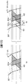
図9は、光情報記録媒体1における信号光306と参照光307の入射角の関係を示す図である。図9(a)は、光情報記録媒体1に入射する信号光306と参照光307を簡略化して示す。図より、信号光306のうち、最内角の信号光306aと最外角の信号光306bは、参照光307とのなす角が大きく違うことがわかる。これは、信号光306は対物レンズ315によって集光するので、光情報記録媒体1への入射角は対物レンズ315を通過した位置によって大きく異なるためである。図9(b)は、図9(a)の光情報記録媒体1内の入射光束オーバーラップ部450を拡大した図を示す。破線で示した光情報記録媒体1の法線に対して、参照光307の主光線の角度をθrとする。また、信号光306のうち最内角の信号光306aの光情報記録媒体1の法線に対する角度をθa、最外角の信号光306bの光情報記録媒体1の法線に対する角度をθbとする。信号光はθaからθbまで角度が変化する。先に述べたように、信号光306の媒体への入射角は対物レンズ315を通過した位置によって大きく異なるため、信号光306と参照光307とのなす角も、位置によって大きく異なる。
図10は、光情報記録媒体1に記録したホログラムにおける、記録時と再生時の参照光角度ずれΔθrと、再生光の回折効率ηの関係を示した図である。図9に示す信号光の入射角がθaのときの回折効率を500a、信号光の入射角がθbのときの回折効率を500bとする。
信号光と参照光のなす角をθrs、信号光の入射角をθsとするとき、回折効率ηは
信号光と参照光のなす角をθrs、信号光の入射角をθsとするとき、回折効率ηは

で表される。ここで、λは光源301の波長、nは光情報記録媒体1の屈折率、Lは光情報記録媒体1の記録層の厚みを表す。
数1より、回折効率ηは記録時と再生時の参照光角度ずれΔθrによってsinc関数で変化する。また、信号光と参照光のなす角θrsや信号光の入射角θsによって、再生時の参照光角度ずれΔθrに対する回折効率ηの変化する割合が大きく異なる。つまり、角度選択性が大きく異なることを意味する。図10に示すように、信号光の入射角がθaのときの回折効率500aは、信号光と参照光のなす角θrsおよび信号光の入射角θsが小さいので、参照光角度ずれΔθrに対する回折効率の変化が小さい、つまり信号光306aで構成されるホログラムの角度選択性が広いといえる。一方、信号光の入射角がθbのときの回折効率500bは、信号光と参照光のなす角θrsおよび信号光の入射角θsが大きいので、参照光角度ずれΔθrに対する回折効率の変化が大きい、つまり信号光306bで構成されるホログラムの角度選択性が狭いといえる。一例として、図10に示すように再生時参照光角度ずれがΔθ’だったとき、回折効率500aは角度選択性が広いために所定量の回折効率が発生するが、回折効率500bは角度選択性が狭いために回折効率がNullとなる。このように、信号光を画素ごとに分離して考えたとき、信号光位置によって参照光とのなす角度が異なるので、再生時の参照光角度ずれが発生したときに検出される回折効率ηも大きく異なる。つまり、再生時の参照光角度ずれを利用することで、なす角θrsが大きい信号光の回折効率のみを十分小さい値にすることが可能になる。
一般的に、ビームウエスト面上では隣接ブックのオーバーラップを避ける必要がある。その観点で、図8に示した最内角の信号光306aと最外角の信号光306bいずれも、隣接ブックとオーバーラップを避けることが原則とされている。しかし、本実施例の特徴とするところは、図10に示すように最内角の信号光306aで構成されるホログラムの角度選択性と比べて、最外角の信号光306bで構成されるホログラムの角度選択性は狭いので、例えば選択ブックに対して隣接ブックのホログラムを図10に示したΔθ’ずらして記録することで、最内角の信号光306bによるホログラムの隣接ブックのクロストークがたとえ所定量オーバーラップしていても、角度選択性の観点から影響を十分に小さくすることができることにある。
図11は、光情報記録媒体1に記録された選択ブック401(縦線の網掛けで示す)と隣接ブック402(破線の枠で示す)および隣接ブック403(一点鎖線の枠で示す)の位置関係を、最内角の信号光成分を追記して示した図である。選択ブック401のうち最内角の信号光を401a、隣接ブック402のうち最内角の信号光を402a、選択ブック403のうち最内角の信号光を403aとする。また、401a、402a、403aがビームウエスト面上で形成するビームウエストサイズをφaとする。図8に示したように、ビームウエスト面での信号光ビームウエストサイズは最外角よりも最内角の方が小さいことと、図10に示したように最内角の信号光306aで構成されるホログラムの角度選択性と比べて、最外角の信号光306bで構成されるホログラムの角度選択性は狭いことを利用して、各ブックが互いにビームウエスト面上で少なくともφaずらして、各ブックを光情報記録媒体1に記録する。
図12は、本実施例におけるホログラム記録方法を示す。図12(a)は選択ブックの記録の様子を示す。参照光の入射角をθrとして選択ブック401を所定の位置に記録する。図12(b)は隣接ブック402の記録の様子を示す。図のように隣接ブック402を選択ブック401に対してビームウエスト面上でφcずらして記録する。このときずらし量φcは、最内角の信号光306aが形成するビームウエストサイズφa以上、最外角の信号光306bが形成するビームウエストサイズφb以下に設定する。また、参照光の入射角はθr+Δθcと、選択ブック401を記録したときの参照光角度に対して、Δθcだけずらして入射させる。Δθcの値は、例えば最外角の信号光の回折効率が十分小さくなるような値を選べばよい。以下、他の隣接ブックも相対的に所定の角度だけずらして記録する。
なお、Δθcは上記の値に制限されないことは言うまでもない。回折効率ηが十分小さくなるような角度であればどのような値でも構わない。また、Δθcは正負どちらの回転方向でも構わない。
図13は、図11のように記録したブックにおいて、選択ブック401を再生するときの空間フィルタ314までの信号光の進行の様子を示している。図13(a)は、選択ブック401と隣接ブック402の信号光の関係を示す。参照光307は、選択ブック401を再生するため、記録時と同じθrで照射している。選択ブック401を回折した信号光411は図のように伝搬して空間フィルタ314を通過する。このとき、隣接ブック402も参照光307が一部照射されて回折するので、信号光412が進行する。しかし、最内角の信号光成分は物理的に分離されているので、空間フィルタ314を通過できずに遮光される。一方、最外角の信号光成分は一部オーバーラップしているので、一部の光が422のように空間フィルタ314を通過する。ところが隣接ブックは、再生時の参照光入射角がΔθcずれているために、回折効率ηを小さくすることができ、その結果クロストークを小さくすることができる。回折光量はΔθcを調整することによって、十分小さい値にすることが可能である。
図13(b)は、選択ブック401と隣接ブック403の信号光の関係を示す。こちらも、図13(a)と同様の現象が生じる。隣接ブック403は参照光307が一部照射されて回折するので、信号光413が進行する。しかし、最内角の信号光成分は物理的に分離されているので、空間フィルタ314を通過できずに遮光される。一方、最外角の信号光成分は一部オーバーラップしているので、一部の光が423のように空間フィルタ314を通過する。ところが隣接ブックは、再生時の参照光入射角が所定量ずれているために、回折効率ηを小さくすることができ、その結果クロストークを小さくすることができる。回折光量は参照光入射角ずれ量を調整することによって、十分小さい値にすることが可能である。
以上のように、本実施例は、信号光の光軸が光情報記録媒体1に対して所定量傾いているために、空間光変調器312の各画素が光情報記録媒体1で形成するビームウエストサイズが異なることと、空間光変調器312の各画素の信号光と参照光とのなす角が異なるために、ホログラムの角度選択性が画素ごとに異なることを巧みに利用して、角度選択性が広いホログラムについてはオーバーラップを避け、角度選択性が狭いホログラムについては隣接ブックと参照光入射角度を所定量ずらして記録することで、オーバーラップしていても隣接ブックのクロストークを十分小さくすることができる。これによって、簡素な構成で記録容量を大容量化することが可能となる。
特許文献1のような従来技術は、記録ブックによって参照光入射角を変えるという記載はあるが、光情報記録媒体1のビームウエスト面でブックをオーバーラップさせる記載はなく、再生時の隣接ブック回折光は空間フィルタで分離すると記載されている。また、オーバーラップ量をどのような範囲にするということも考えられていない。本実施例は、空間光変調器312の各画素が光情報記録媒体1で形成するビームウエストサイズと、参照光とのなす角度によってホログラムの角度選択性が変化することに着目して、再生時に隣接ブックの信号光が一部通過した場合でもクロストークの影響を十分小さくすることができる構成を実現している。
なお、選択ブックと隣接ブックの間隔は、最外角の信号光が光情報記録媒体1のビームウエスト面で形成するビームウエストサイズφb以下、最外角の信号光が光情報記録媒体1のビームウエスト面で形成するビームウエストサイズφa以上であればどの間隔でも構わない。
以上のように、従来とは異なり選択ブックに対して隣接ブックを所定量オーバーラップさせて記録する。隣接ブックの間隔は、最外角の入射光のビームウエストサイズφb以下、最内角の入射光のビームウエストサイズφa以上とする。記録するときの参照光角度は、選択ブックに対して隣接ブックのとき所定量ずらして記録する。このときの角度ずれ量は、再生時に空間フィルタを透過する隣接ブックの回折光量が信号性能に影響しないようなレベルとなるように調整する。このような記録方法によって、再生時は最外角の信号光が一部空間フィルタを透過しても回折光量を0もしくは最小値に抑えることができる。したがって、簡素な構成で記録容量を大容量化することが可能な、光情報記録再生方法およびその方法を用いた光情報記録再生装置を実現することができる。
実施例2では、角度多重で複数ページを記録する方法に関して説明する。図14は、参照光の入射角度を変化させて角度多重記録を行ったときの、ホログラム記録について示した図である。一例として、一つのブックにnページ記録することを想定する。図14(a)は、選択ブック401に複数ページを記録する様子を示す。選択ブック401に参照光の角度をθr=θ1、θ2、θ3、・・・θnといったように所定量変化させてnページ記録する。なお、nは2以上の整数とする。
図14(b)は、隣接ブック402に複数ページを記録する様子を示す。選択ブック401に対してビームウエスト面で所定量離れた位置に隣接ブック402を記録する。このとき選択ブック401と隣接ブック402は、ビームウエスト面においてΔdオーバーラップして記録する。オーバーラップ量Δdは、最内角の入射光のビームウエストサイズをφa、最外角の入射光のビームウエストサイズをφbとしたとき、0以上φb-φa以下の範囲とする。つまり、選択ブック401に対して隣接ブック402はφ1以上φ2以下の範囲でずらして記録する。
なお、記録時の参照光の入射角度は、選択ブック401に対してそれぞれΔθcだけずらし、θr=θ1+Δθc、θ2+Δθc、θ3+Δθc、・・・θn+Δθcとしてnページ記録する。Δθcは、選択ブック401再生時に隣接ブックの回折効率ηが小さくなる値であれば、どのような値でも構わない。また、Δθcを全ての角度で固定にしてもよいし、固定値にせず角度によって変動させても構わない。例えば、ページの角度間隔の半分に制御してもよい。この場合、θ1とθ2の間はΔθc=(θ2-θ1)/2の値とする。また、θ2とθ3の間はΔθc=(θ3-θ2)/2の値とする。ページ間角度が一定でないときは、Δθcの値もページ間によって変動する。以下、他の隣接ブックも相対的に所定の角度だけずらして記録する。
以上のような記録方法により、実施例1と同様に、ビームウエスト面上で所定量オーバーラップしてホログラムを複数ページ記録した場合でも、隣接ブックのクロストークを十分小さくすることが可能である。
実施例3では、1つのブックでページによって所定量ずらして記録する方法について説明する。光情報記録媒体1の所定の位置にどれだけのホログラムを多重記録できるかという指標に、Mナンバーという値が使われる。Mナンバーは、光情報記録媒体1の材料や厚さによって決まる固有値である。一方、ホログラムの回折効率ηは、Mナンバーに比例し、多重数に反比例するという特性を持つ。Mナンバー消費の観点で所定の位置に記録するホログラム数は、できるだけ少なくすることが重要となる。そこで、図15に示すように、Mナンバーの消費を抑えるように1つのブックをページによって所定量ずらして記録する記録方法を用いることができる。以降、各複数ページのまとまりをスタック、上記のような記録方法をショートスタックと呼ぶこととする。本実施例では、nページ記録のうちページ1からページiと、ページi+1からページnの2つのスタックに分けて記録するときの、光情報記録媒体1のビームウエスト面上における選択ブック401と隣接ブック402の位置関係を示している。なお、nは2以上の整数、iは0以上の整数とする。
図15(a)は、従来のショートスタックについて示した図である。選択ブック401を記録するとき、ページ1からページiを同一の位置に角度多重で記録した後、ページi+1からページnを所定量Δtずらした位置に角度多重で記録する。続いて、隣接ブック402のページ1からページiを、選択ブック401のページ1からページiを記録した位置に対してビームウエスト面で互いに重ならないように記録する。次に、隣接ブック402のページi+1からページnを、選択ブック401のページi+1からページnを記録した位置に対してビームウエスト面で互いに重ならないように記録する。このように記録することでMナンバーの消費を抑えた記録を行うことが可能となる。
図15(b)は、本実施例のショートスタックについて示した図である。選択ブック401を記録するとき、ページ1からページiを同一の位置に角度多重で記録した後、ページi+1からページnを所定量Δtずらした位置に角度多重で記録する。続いて、隣接ブック402のページ1からページiを、選択ブック401のページ1からページiを記録した位置に対してビームウエスト面でΔdだけオーバーラップして記録する。このときのオーバーラップ量Δdは、最内角の入射光のビームウエストサイズをφa、最外角の入射光のビームウエストサイズをφbとしたとき、0以上φb-φa以下の範囲とする。つまり、選択ブック401に対して隣接ブック402はφ1以上φ2以下の範囲ずらして記録する。記録時の参照光の入射角度は、選択ブック401に対してそれぞれΔθだけずらして記録する。Δθは、選択ブック401再生時に隣接ブックの回折効率ηが小さくなる値であれば、どのような値でも構わない。
次に、隣接ブック402のページi+1からページnを記録するときも、選択ブック401のページi+1からページnを記録した位置に対してビームウエスト面でΔdだけオーバーラップして記録する。このときのオーバーラップ量Δdは、最内角の入射光のビームウエストサイズをφa、最外角の入射光のビームウエストサイズをφbとしたとき、0以上φb-φa以下の範囲とする。つまり、選択ブック401に対して隣接ブック402はφ1以上φ2以下の範囲ずらして記録する。記録時の参照光の入射角度は、選択ブック401に対してそれぞれΔθだけずらして記録する。Δθは、選択ブック401再生時に隣接ブックの回折効率ηが小さくなる値であれば、どのような値でも構わない。
このように記録することで、Mナンバーの消費を抑え、かつ記録容量を大容量することが可能となる。
なお、本実施例では1つのブックを2つのスタックに分けて記録する記録方法について記載したが、2つに限定されないことは言うまでもない。3つ以上のスタックとしても構わない。また、Δtの量はビームウエスト面で形成されるビームウエストサイズ以下であればいくつでも構わない。
また、実施例中ではΔdの値はスタックの位置によらず固定値としているが、スタックの位置によって信号性能がもっとも安定する値に変化させてもよい。
実施例4では、光情報記録媒体の種類及び/又は光情報記録媒体の領域に応じて、ビームウエストのオーバーラップ量を変えて記録する方法について説明する。
実施例3で述べたように、光情報記録媒体へのホログラム多重記録数は、Mナンバーによって決定する。Mナンバーが光情報記録媒体毎にばらつきを持ったとき、または複数のMナンバーの規格の光情報記録媒体が生じたとき、さらに光情報記録媒体の領域内でMナンバーが異なるときには、Mナンバー値に応じて多重記録数とビームウエスト部のオーバーラップ量を変化させて記録再生を行う必要がある。
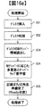
図16(a)は、光情報記録再生装置10に光情報記録媒体1を挿入したとき、媒体の種類に応じた記録または再生の準備を完了させるまでの動作フローを示す。
図16(a)に示すように媒体を挿入すると(631)、光情報記録再生装置10は、挿入された媒体がホログラフィ記録再生媒体であるかどうかディスク判別を行う(632)。
続いて、挿入された媒体のMナンバーの情報を媒体の所定位置から取得する(633)。Mナンバーが判明したとき、Mナンバーに応じた多重数およびビームウエスト部のオーバーラップ量を学習させる(634)。例えば、Mナンバーが小さいときは多重数を少なく設定する必要があるが、多重数が少ないということはページ間隔の角度を大きくとることができるため、オーバーラップ量は大きくなる。反対に、Mナンバーが大きいときは多重数を多く設定できるが、多重数が多いということはページ間隔の角度が小さくなるため、オーバーラップ量は小さくなる。媒体に適切な多重数とオーバーラップ量学習後、光情報記録再生装置10は、記録または再生の準備が完了する(635)。そして、光情報記録媒体1の種類に応じたオーバーラップ量で記録を実行する。
図16(b)は、光情報記録再生装置10に光情報記録媒体1を挿入したとき、媒体の領域内でMナンバーが異なる場合に対応した、記録または再生の準備を完了させるまでの動作フローを示す。
図16(b)のステップ(641)と(642)は、図16(a)と同様のため、説明を割愛する。媒体判別後に、挿入された媒体の領域内で異なるMナンバーの情報を、媒体の所定位置から取得する(633)。次に、Mナンバーに対応した領域毎に適切な多重数およびビームウエスト部のオーバーラップ量を学習させる(644)。これにより、領域内で複数のMナンバーが生じた場合でも、記録再生性能を十分に活用することが可能である。適切な多重数とオーバーラップ量学習後、光情報記録再生装置10は、記録または再生の準備が完了する(645)。そして、光情報記録媒体1の領域に応じたオーバーラップ量で記録を実行する。
以上のように、媒体のMナンバーを事前に媒体に記録させておき、その情報を予め学習する動作フローを行うことで、媒体の種類や媒体内でMナンバーが異なる場合も、適切な多重数およびオーバーラップ量で記録再生することが可能である。
なお、本実施例において、オーバーラップ量だけでなく、参照光角度のずれ量Δθcも光情報記録媒体1の種類及び/又は領域に応じて変化させてもよい。これにより、より大容量化が可能となる。
なお、ステップ(634)、(644)におけるオーバーラップ量は、学習して求めるのではなく、予め定められた値(例えば、規格で定められた値)を用いてもよい。
なお、本発明は上記した実施例に限定されるものではなく、様々な変形例が含まれる。例えば、上記した実施例は本発明を分かりやすく説明するために詳細に説明したものであり、必ずしも説明した全ての構成を備えるものに限定されるものではない。また、ある実施例の構成の一部を他の実施例の構成に置き換えることが可能であり、また、ある実施例の構成に他の実施例の構成を加えることも可能である。また、各実施例の構成の一部について、他の構成の追加・削除・置換をすることが可能である。
1・・・光情報記録媒体、10・・・光情報記録再生装置、11・・・ピックアップ、12・・・再生用参照光光学系、13・・・ディスクキュア光学系、14・・・ディスク回転角度検出用光学系、81・・・アクセス制御回路、82・・・光源駆動回路、83・・・サーボ信号生成回路、84・・・サーボ制御回路、85・・・信号処理回路、86・・・信号生成回路、87・・・シャッタ制御回路、88・・・ディスク回転モータ制御回路、89・・・コントローラ、90…入出力制御回路、91…外部制御装置、301・・・光源、302・・・コリメートレンズ、303・・・シャッタ、305・・・PBSプリズム、306・・・信号光、307・・・参照光、308・・・ビームエキスパンダ、309・・・位相マスク、310・・・リレーレンズ、311・・・PBSプリズム、312・・・空間光変調器、313・・・リレーレンズ、314・・・空間フィルタ、315・・・対物レンズ、316・・・偏光方向変換素子、320・・・アクチュエータ、321・・・レンズ、322・・・レンズ、323・・・アクチュエータ、324・・・ミラー、325・・・光検出器
Claims (14)
- 光情報記録再生方法において、
信号光と参照光を生成する生成工程と、
前記生成工程で生成された信号光を変調する変調工程と、
前記変調工程で変調された信号光を光情報記録媒体の法線に対して所定角度傾けて入射させると共に、前記生成工程で生成された参照光を前記光情報記録媒体に入射させる入射工程と、
前記入射工程で光情報記録媒体に入射した信号光と参照光を前記光情報記録媒体上で干渉させて情報を記録する記録工程と、有し、
前記記録工程は、
第1の信号光と第1の参照光との干渉で前記光情報記録媒体の所定位置に第1のホログラムを形成する第1の記録工程と、
第2の信号光と第2の参照光との干渉で前記第1のホログラムの隣の前記光情報記録媒体の位置に第2のホログラムを形成する第2の記録工程と、を有し、
前記第1の記録工程または前記第2の記録工程では、前記第1のホログラムにおける前記第1の信号光の第1のビームウエストと、前記第2のホログラムにおける前記第2の信号光の第2のビームウエストを、前記光情報記録媒体のビームウエスト面上において互いに所定量オーバーラップさせ、かつ、前記第1のホログラムを形成するときの前記第1の参照光の入射角度と、前記第2のホログラムを形成するときの前記第2の参照光の入射角度を、互いに所定量ずらす、ことを特徴とする光情報記録再生方法。 - 請求項1に記載の光情報記録再生方法において、
前記第1の記録工程または前記第2の記録工程において、
前記変調工程で用いられる空間光変調素子を構成する画素のうち、前記参照光とのなす角が最も小さくなる画素の信号光によって形成されるホログラムのビームウエストサイズをφ1、前記参照光とのなす角が最も大きくなる画素の信号光によって形成されるホログラムのビームウエストサイズをφ2とするとき、前記ビームウエスト面上で前記第1のホログラムに対して前記第2のホログラムを少なくともφ1以上かつφ2以下ずらして記録することを特徴とする光情報記録再生方法。 - 請求項2に記載の光情報記録再生方法において、
前記第1の記録工程または前記第2の記録工程において、前記第1の参照光に対する前記第2の参照光の入射角度ずれ量を、少なくとも前記ビームウエストサイズφ2を形成する信号光によるホログラムの回折光量が最初に略0となる量に制御することを特徴とする光情報記録再生方法。 - 請求項2に記載の光情報記録再生方法において、
前記第1の記録工程または前記第2の記録工程において、前記第1の参照光の複数の入射角度をθr=θ1、θ2、・・・、θn(nは2以上の整数)とし、前記第2の参照光の複数の入射角度をθr=θ1+Δθ、θ2+Δθ、・・・、θn+Δθとするとき、前記参照光入射角度ずれ量Δθを、少なくとも前記ビームウエストサイズφ2を形成する信号光によるホログラムの回折光量が略0もしくは最小となる量に制御することを特徴とする光情報記録再生方法。 - 請求項4に記載の光情報記録再生方法において、
前記第1の記録工程または前記第2の記録工程において、前記参照光入射角度ずれ量Δθを、参照光の入射角度によって互いに異なる量に制御することを特徴とする光情報記録再生方法。 - 請求項4に記載の光情報記録再生方法において、
前記第1の記録工程または前記第2の記録工程において、前記ホログラムを形成する参照光入射角度のうち、1番目からi番目(iは0以上の整数)までのホログラムと、i+1番目からn番目(nは2以上の整数)までのホログラムは、互いに所定量ずれた位置に形成させることを特徴とする光情報記録再生方法。 - 請求項1に記載の光情報記録再生方法において、
前記第1の記録工程または前記第2の記録工程において、前記光情報記録媒体の種類及び/又は領域に応じて、記第1のホログラムと前記第2のホログラムのビームウエスト面上においてオーバーラップさせる量を変えることを特徴とする光情報記録再生方法。 - 光情報記録再生装置において、
信号光と参照光を生成する光学系と、
前記光学系で生成された信号光を変調する空間光変調部と、
前記空間光変調部で変調された信号光を光情報記録媒体の法線に対して所定角度傾けて集光させる対物レンズと、
前記光学系で生成された参照光の前記光情報記録媒体への入射角度を変える光学素子と、
前記光情報記録媒体と前記対物レンズの相対位置を制御する移動部と、
前記光学素子と前記移動部を制御する制御部と、を備え、
前記制御部は、
第1の信号光と第1の参照光との干渉で前記光情報記録媒体の所定位置に第1のホログラムを形成し、
第2の信号光と第2の参照光との干渉で前記第1のホログラムの隣の前記光情報記録媒体の位置に第2のホログラムを形成し、
前記第1のホログラムにおける前記第1の信号光の第1のビームウエストと、前記第2のホログラムにおける前記第2の信号光の第2のビームウエストを、前記光情報記録媒体のビームウエスト面上において互いに所定量オーバーラップさせ、かつ、前記第1のホログラムを形成するときの前記第1の参照光の入射角度と、前記第2のホログラムを形成するときの前記第2の参照光の入射角度を、互いに所定量ずらして、前記光情報記録媒体に情報を記録するよう、前記光学素子と前記移動部を制御することを特徴とする光情報記録再生装置。 - 請求項8に記載の光情報記録再生装置において、
前記制御部は、前記空間光変調部を構成する画素のうち、前記参照光とのなす角が最も小さくなる画素の信号光によって形成されるホログラムのビームウエストサイズをφ1、前記参照光とのなす角が最も大きくなる画素の信号光によって形成されるホログラムのビームウエストサイズをφ2とするとき、前記ビームウエスト面上で前記第1のホログラムに対して前記第2のホログラムが少なくともφ1以上かつφ2以下ずらして記録されるよう、前記移動部を制御することを特徴とする光情報記録再生装置。 - 請求項9に記載の光情報記録再生装置において、
前記第1の参照光に対する前記第2の参照光の入射角度ずれ量が、少なくとも前記ビームウエストサイズφ2を形成する信号光によるホログラムの回折光量が最初に略0となる量となるよう、前記制御部は、前記光学素子を制御することを特徴とする光情報記録再生装置。 - 請求項9に記載の光情報記録再生装置において、
前記第1の参照光の複数の入射角度をθr=θ1、θ2、・・・、θn(nは2以上の整数)とし、前記第2の参照光の複数の入射角度をθr=θ1+Δθ、θ2+Δθ、・・・、θn+Δθとするとき、前記参照光入射角度ずれ量Δθは、少なくとも前記ビームウエストサイズφ2を形成する信号光によるホログラムの回折光量が略0もしくは最小となる量でとなるよう、前記制御部は、前記移動部と前記光学素子を制御することを特徴とする光情報記録再生装置。 - 請求項11に記載の光情報記録再生装置において、
前記参照光入射角度ずれ量Δθは、参照光の入射角度によって互いに異なる量であることを特徴とする光情報記録再生装置。 - 請求項11に記載の光情報記録再生装置において、
前記ホログラムを形成する参照光入射角度のうち、1番目からi番目(iは0以上の整数)までのホログラムと、i+1番目からn番目(nは2以上の整数)までのホログラムが、互いに所定量ずれた位置に形成されるよう、前記制御部は、前記移動部と前記光学素子を制御することを特徴とする光情報記録再生装置。 - 請求項8に記載の光情報記録再生装置において、
前記制御部は、前記光情報記録媒体の種類及び/又は領域に応じて、記第1のホログラムと前記第2のホログラムのビームウエスト面上においてオーバーラップさせる量を変えるよう、前記移動部と前記光学素子を制御することを特徴とする光情報記録再生装置。
Priority Applications (1)
| Application Number | Priority Date | Filing Date | Title |
|---|---|---|---|
| PCT/JP2014/070297 WO2016017020A1 (ja) | 2014-08-01 | 2014-08-01 | 光情報記録再生方法、光情報記録再生装置 |
Applications Claiming Priority (1)
| Application Number | Priority Date | Filing Date | Title |
|---|---|---|---|
| PCT/JP2014/070297 WO2016017020A1 (ja) | 2014-08-01 | 2014-08-01 | 光情報記録再生方法、光情報記録再生装置 |
Publications (1)
| Publication Number | Publication Date |
|---|---|
| WO2016017020A1 true WO2016017020A1 (ja) | 2016-02-04 |
Family
ID=55216955
Family Applications (1)
| Application Number | Title | Priority Date | Filing Date |
|---|---|---|---|
| PCT/JP2014/070297 Ceased WO2016017020A1 (ja) | 2014-08-01 | 2014-08-01 | 光情報記録再生方法、光情報記録再生装置 |
Country Status (1)
| Country | Link |
|---|---|
| WO (1) | WO2016017020A1 (ja) |
Citations (4)
| Publication number | Priority date | Publication date | Assignee | Title |
|---|---|---|---|---|
| WO2008001434A1 (en) * | 2006-06-28 | 2008-01-03 | Fujitsu Limited | Hologram recording device and hologram recording method |
| JP2008071434A (ja) * | 2006-09-14 | 2008-03-27 | Sony Corp | 光ディスク装置、光ディスク、記録制御方法並びに再生制御方法 |
| JP2009087448A (ja) * | 2007-09-28 | 2009-04-23 | Hitachi Ltd | ホログラム記録再生装置及びホログラム記録再生方法 |
| JP2011013531A (ja) * | 2009-07-03 | 2011-01-20 | Sharp Corp | 情報記録方法、2次元情報作成方法、情報再生方法および情報記録媒体 |
-
2014
- 2014-08-01 WO PCT/JP2014/070297 patent/WO2016017020A1/ja not_active Ceased
Patent Citations (4)
| Publication number | Priority date | Publication date | Assignee | Title |
|---|---|---|---|---|
| WO2008001434A1 (en) * | 2006-06-28 | 2008-01-03 | Fujitsu Limited | Hologram recording device and hologram recording method |
| JP2008071434A (ja) * | 2006-09-14 | 2008-03-27 | Sony Corp | 光ディスク装置、光ディスク、記録制御方法並びに再生制御方法 |
| JP2009087448A (ja) * | 2007-09-28 | 2009-04-23 | Hitachi Ltd | ホログラム記録再生装置及びホログラム記録再生方法 |
| JP2011013531A (ja) * | 2009-07-03 | 2011-01-20 | Sharp Corp | 情報記録方法、2次元情報作成方法、情報再生方法および情報記録媒体 |
Similar Documents
| Publication | Publication Date | Title |
|---|---|---|
| JP4778924B2 (ja) | 光情報処理装置と光情報処理方法 | |
| US20070206255A1 (en) | Hologram recorder | |
| JP2009087448A (ja) | ホログラム記録再生装置及びホログラム記録再生方法 | |
| US20060067179A1 (en) | Optical information recording device and optical information reproduction device | |
| CN102385874B (zh) | 再现装置和再现方法 | |
| JP5183667B2 (ja) | 再生装置および再生方法 | |
| US8305862B2 (en) | Optical information recording and reproducing device | |
| JP5581111B2 (ja) | 光情報再生装置および光情報再生方法 | |
| JP5096191B2 (ja) | 光ピックアップおよび、それを用いた光情報再生装置および光情報記録再生装置 | |
| JP4881914B2 (ja) | 光情報記録再生装置及び光情報記録方法 | |
| US8085643B2 (en) | Optical information reproducing apparatus, optical information recording and reproducing apparatus | |
| JP4060813B2 (ja) | ホログラフィック記録装置、ホログラフィック再生装置、及びマスク | |
| JP2014026706A (ja) | ホログラフィックメモリ装置および参照光入射角度調整方法 | |
| CN103123792B (zh) | 光信息记录再现装置和方法 | |
| JP5104695B2 (ja) | 情報記録装置 | |
| JP5816132B2 (ja) | ホログラム用光ピックアップ装置及び光情報記録再生装置 | |
| JP5557787B2 (ja) | 光情報再生装置、光情報記録再生装置 | |
| US20180267464A1 (en) | Hologram recording and reproducing apparatus and hologram recording and reproducing method | |
| WO2016017020A1 (ja) | 光情報記録再生方法、光情報記録再生装置 | |
| WO2015198407A1 (ja) | 光情報記録再生装置、及び光情報記録再生方法 | |
| JP2012069207A (ja) | ホログラフィを用いたホログラフィックメモリ | |
| JP2017004576A (ja) | 光情報記録再生装置および光情報記録再生方法 | |
| JP5802494B2 (ja) | ホログラフィックメモリ再生装置、ホログラフィックメモリ再生方法およびホログラム記録媒体 | |
| JP4882803B2 (ja) | ホログラム記録装置及びホログラム再生装置 | |
| US20150194177A1 (en) | Optical information recording device and optical information recording method |
Legal Events
| Date | Code | Title | Description |
|---|---|---|---|
| 121 | Ep: the epo has been informed by wipo that ep was designated in this application |
Ref document number: 14898400 Country of ref document: EP Kind code of ref document: A1 |
|
| NENP | Non-entry into the national phase |
Ref country code: DE |
|
| 122 | Ep: pct application non-entry in european phase |
Ref document number: 14898400 Country of ref document: EP Kind code of ref document: A1 |
|
| NENP | Non-entry into the national phase |
Ref country code: JP |