WO2016017002A1 - Système de stockage - Google Patents
Système de stockage Download PDFInfo
- Publication number
- WO2016017002A1 WO2016017002A1 PCT/JP2014/070224 JP2014070224W WO2016017002A1 WO 2016017002 A1 WO2016017002 A1 WO 2016017002A1 JP 2014070224 W JP2014070224 W JP 2014070224W WO 2016017002 A1 WO2016017002 A1 WO 2016017002A1
- Authority
- WO
- WIPO (PCT)
- Prior art keywords
- data
- compressed
- storage
- parity
- fmpk
- Prior art date
Links
Images


Classifications
-
- G—PHYSICS
- G06—COMPUTING; CALCULATING OR COUNTING
- G06F—ELECTRIC DIGITAL DATA PROCESSING
- G06F11/00—Error detection; Error correction; Monitoring
- G06F11/07—Responding to the occurrence of a fault, e.g. fault tolerance
- G06F11/14—Error detection or correction of the data by redundancy in operation
- G06F11/1402—Saving, restoring, recovering or retrying
- G06F11/1415—Saving, restoring, recovering or retrying at system level
-
- G—PHYSICS
- G06—COMPUTING; CALCULATING OR COUNTING
- G06F—ELECTRIC DIGITAL DATA PROCESSING
- G06F11/00—Error detection; Error correction; Monitoring
- G06F11/07—Responding to the occurrence of a fault, e.g. fault tolerance
- G06F11/08—Error detection or correction by redundancy in data representation, e.g. by using checking codes
- G06F11/10—Adding special bits or symbols to the coded information, e.g. parity check, casting out 9's or 11's
- G06F11/1076—Parity data used in redundant arrays of independent storages, e.g. in RAID systems
-
- G—PHYSICS
- G06—COMPUTING; CALCULATING OR COUNTING
- G06F—ELECTRIC DIGITAL DATA PROCESSING
- G06F11/00—Error detection; Error correction; Monitoring
- G06F11/07—Responding to the occurrence of a fault, e.g. fault tolerance
- G06F11/16—Error detection or correction of the data by redundancy in hardware
- G06F11/20—Error detection or correction of the data by redundancy in hardware using active fault-masking, e.g. by switching out faulty elements or by switching in spare elements
- G06F11/2053—Error detection or correction of the data by redundancy in hardware using active fault-masking, e.g. by switching out faulty elements or by switching in spare elements where persistent mass storage functionality or persistent mass storage control functionality is redundant
- G06F11/2094—Redundant storage or storage space
-
- G—PHYSICS
- G06—COMPUTING; CALCULATING OR COUNTING
- G06F—ELECTRIC DIGITAL DATA PROCESSING
- G06F3/00—Input arrangements for transferring data to be processed into a form capable of being handled by the computer; Output arrangements for transferring data from processing unit to output unit, e.g. interface arrangements
- G06F3/06—Digital input from, or digital output to, record carriers, e.g. RAID, emulated record carriers or networked record carriers
-
- G—PHYSICS
- G06—COMPUTING; CALCULATING OR COUNTING
- G06F—ELECTRIC DIGITAL DATA PROCESSING
- G06F2201/00—Indexing scheme relating to error detection, to error correction, and to monitoring
- G06F2201/805—Real-time
Definitions
- the present invention relates to a data recovery technique in a storage system.
- RAID Redundant Arrays of Inexpensive / Independent Disks
- the RAID technology is a technology for calculating redundant data such as parity from write data received from a host device such as a host computer, and distributing and storing the write data and parity in different storage devices.
- Patent Literature 1 discloses a storage system having a function such as parity generation on the storage device side in order to suppress a data transfer amount generated between the storage controller and the storage device.
- Patent Document 1 discloses that data recovery is performed using a parity generation function provided on the storage device side. However, it is still necessary to read out all data in the storage device. It is difficult to significantly reduce the time for recovery processing.
- a storage system includes a controller and a plurality of storage devices, and configures a RAID group with (n + m) storage devices, and write data from a host computer is stored in n storage devices. Redundant data generated from n data is stored in m storage devices.
- the controller reads the compressed data and redundant data from each of the storage devices in the RAID group that do not have a failure, The read compressed data is transmitted to the data recovery destination storage device.
- the amount of data transferred at the time of data recovery can be reduced, and the data recovery time can be shortened.
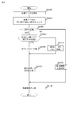
- FIG. 1 is a configuration diagram of a storage system according to an embodiment of the present invention.
- FIG. It is a block diagram of FMPK. It is explanatory drawing of the content of the storage area in a RAID group. It is a figure explaining the relationship between the storage space of a RAID group and a logical unit (LU). It is a figure which shows the structure of a device management table. It is a figure which shows the structure of an RG management table. It is a figure which shows the structure of LU management table. It is explanatory drawing of the management method of the storage area in FMPK. It is a figure which shows the structure of a mapping table. It is a figure which shows the structure of a state management table.
- LU logical unit
- FIG. 6 is a diagram illustrating a format of response information with respect to a compressed Read command 3000.
- FIG. It is a figure showing the format of the compression copy Write command. It is a figure showing the format of the compression parity calculation Write command. It is a figure showing the format of the response information with respect to a compression copy Write command.
- FIG. 10 is a diagram illustrating an example of stripe lines supported by the storage system according to the third embodiment. 12 is a detailed flowchart of collection copy performed in the storage system according to the third embodiment.
- FIG. 10 is a diagram illustrating a format of a compressed parity operation write command supported by the storage system according to the third embodiment.
- FIG. 1 shows a configuration of a storage system 1 according to the first embodiment.
- the storage system 1 includes a storage controller (DKC) 10 and a plurality of storage devices (200, 200 ') connected to the storage controller 10.
- DKC storage controller
- FIG. 1 shows a configuration of a storage system 1 according to the first embodiment.
- the storage system 1 includes a storage controller (DKC) 10 and a plurality of storage devices (200, 200 ') connected to the storage controller 10.
- DKC storage controller
- the storage devices 200 and 200 ' are final storage media for storing write data from a host device such as the host 2.
- the storage system 1 uses an FMPK (Flash Memory PacKage) that uses a nonvolatile semiconductor memory such as a flash memory as a storage medium in addition to an HDD (Hard Disk Drive) 200 ′ that uses a magnetic disk as a recording medium as a final storage device. ) 200 can be used.
- FMPK Flash Memory PacKage
- HDD Hard Disk Drive
- the storage devices 200 and 200 ′ communicate with the storage controller 10 (hereinafter abbreviated as “DKC 10”) according to the SAS (Serial Attached SCSI) standard.
- SAS Serial Attached SCSI
- the DKC 10 manages a plurality of FMPKs as one or a plurality of RAID (Redundant Arrays of Independent / Independent Disks) groups 145.
- RAID Redundant Arrays of Independent / Independent Disks
- One or more hosts 2 and a management terminal 4 are connected to the DKC 10.
- the DKC 100 and the host 2 are connected via a SAN (Storage Area Network) 1 formed using a fiber channel as an example.
- the DKC 10 and the management terminal 4 are connected via a network 150 formed using Ethernet as an example.
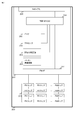
- the DKC 10 includes at least a processor 11, a host interface (denoted as “host IF” in the figure) 12, a disk interface (denoted as “disk IF” in the figure) 13, a memory 14, and a parity operation circuit 15.
- the processor 11, the host IF 12, the disk IF 13, the memory 14, and the parity calculation circuit 15 are interconnected via a mutual coupling switch (mutual coupling SW) 16.
- a plurality of these components are mounted in the DKC 10 in order to ensure high performance and high availability. However, a configuration in which only one of these components is provided in the DKC 10 may be used.
- the disk IF 13 has at least an interface controller 132 (indicated as “SAS-CTL” in the drawing) for communicating with the buffer 131, the storage devices 200 and 200 ', and a transfer circuit (not shown).
- the interface controller 132 is for converting a protocol (SAS in one example) used by the storage devices 200 and 200 'into a communication protocol (PCI-Express as an example) used in the DKC 10.
- SAS-CTL a SAS controller (hereinafter abbreviated as “SAS-CTL”) is used as the interface controller 132.
- SAS-CTL a SAS controller
- FIG. 1 only one SAS-CTL 132 is described in one disk IF 13, but a configuration in which a plurality of SAS-CTLs 132 exist in one disk IF 13 may be adopted.
- the disk IF 13 reads data from the FMPK 200, for example, and temporarily stores the read data in the buffer 131.
- the data stored in the buffer 143 is transmitted to the memory 14 or another buffer of the disk IF 13 by the transfer circuit.
- the buffer 131 is composed of a volatile semiconductor memory, for example, but may be composed of a nonvolatile memory.
- the host IF 12 like the disk IF 13, has at least an interface controller, a buffer, and a transfer circuit (not shown).
- the interface controller is for converting a communication protocol (for example, fiber channel) used between the host 2 and the DKC 10 and a communication protocol used inside the DKC 10.
- the buffer is for temporarily storing data from the host 2 (inversely, it may be used for temporarily storing data to be transferred from the memory 14 to the host 2).
- the parity operation circuit 15 is hardware that generates redundant data required for RAID technology. Examples of redundant data generated by the parity operation circuit 15 include exclusive OR (XOR) and Reed-Solomon code.
- the processor 11 processes an I / O request coming from the host IF 12.
- the memory 14 is used to store programs executed by the processor 11 and various management information of the storage system 1 used by the processor.
- the memory 14 is also used for temporarily storing I / O target data for the storage devices 200 and 200 '.
- a storage area in the memory 14 that is used to temporarily store I / O target data for the storage devices 200 and 200 ′ is referred to as “cache”.
- the memory 14 is configured by a volatile storage medium such as DRAM or SRAM. However, as another embodiment, the memory 14 may be configured by using a nonvolatile memory.
- the storage system 1 can be equipped with a plurality of types of storage devices such as the FMPK 200 and the HDD 200 '.
- the following description is based on the assumption that only the FMPK 200 is mounted in the storage system 1 unless otherwise specified.
- the FMPK 200 includes a device controller (FM controller) 201 and a plurality of FM chips 210.
- the FM controller 201 includes a memory 202, a processor 203, a compression / decompression circuit 204 for compressing / decompressing data, a parity operation circuit 205 for calculating parity, a SAS-CTL 206, and an FM-IF 207.
- the memory 202, the processor 203, the compression / decompression circuit 204, the parity operation circuit 205, the SAS-CTL 206, and the FM-IF 207 are interconnected via an internal connection switch (internal connection SW) 208.
- SAS-CTL 206 is an interface controller for performing communication between the FMPK 200 and the DKC 10.
- the SAS-CTL 206 is connected to the SAS-CTL 132 of the DKC 10 via a transmission line (SAS link).
- the FM-IF 207 is an interface controller for performing communication between the FM controller 201 and the FM chip 210.
- the processor 203 performs processing related to various commands coming from the DKC 10.
- the memory 202 stores programs executed by the processor 203 and various management information.
- a volatile memory such as a DRAM is used.
- a nonvolatile memory may be used for the memory 202.
- the compression / decompression circuit 204 is hardware having a function of compressing data or decompressing the compressed data.
- the parity operation circuit 205 has hardware having a function similar to that of the parity operation circuit 15 included in the DKC 10, that is, a redundant data generation function required in the RAID technology.
- the FM chip 210 is a nonvolatile semiconductor memory chip, and is a NAND flash memory as an example.
- data is read / written in units of pages in the flash memory, and data erasure is performed in units of blocks that are a set of a plurality of pages.
- a page once written cannot be overwritten, and in order to rewrite a page once written, it is necessary to erase the entire block including the page. Therefore, the FMPK 200 does not directly provide the storage area of the FM chip 210 to the DKC 10 to which the FMPK 200 is connected, but provides a logical storage space.
- the FMPK 200 can compress the write data from the DKC 10 and store it in the FM chip 210 by the compression / decompression circuit 204. However, for DKC 10, in principle, data compression is performed transparently.
- the FMPK 200 provides a storage space (logical address space) of a predetermined size to the DKC 10.
- the DKC 10 writes data to the FMPK 200, it issues a write command specifying the address in the logical address space and the size of the write target data.
- the DKC 10 transmits to the FMPK 200 a write command (and 48 KB write data) for writing 48 KB data at the head (address 0) of the logical address space.
- the FMPK 200 compresses the 48 KB data to result in 8 KB compressed data, and the 8 KB compressed data is stored in the FM chip 210.
- the 48 KB data stored earlier is read by issuing a read command designating the head of the logical address space (address 0) and the read data size (eg, 48 KB). be able to.
- the FMPK 200 operates to expand (restore) 8 KB of compressed data to 48 KB by the compression / decompression circuit 204 and return the expanded data to the DKC 10. Therefore, the DKC 10 recognizes as if the data is stored in the uncompressed state in the logical address space (even if the data is actually compressed and stored).
- data compression / decompression is performed by hardware such as the compression / decompression circuit 204 .
- data compression / decompression is not necessarily performed using hardware.
- Data may be compressed and decompressed by the processor 203 executing a program that performs compression and decompression.
- the processor 203 may execute the parity calculation by executing a program that performs the parity calculation.
- the FMPK 200 has the compression / decompression function and the parity calculation function has been described above.
- the FMPK 200 that does not have the compression / decompression function or the parity calculation function may exist in the storage system 1. . If the FMPK 200 does not have a compression / decompression function, the data is not compressed and stored. When the FMPK 200 does not have a parity calculation function, the DKC 10 generates a parity.
- the storage system 1 manages a plurality of FMPKs 200 as a single RAID (Redundant Arrays of Independent / Independent Disks) group.
- RAID Redundant Arrays of Independent / Independent Disks
- the data stored in the failed FMPK 200 is used by using the remaining data in the FMPK 200. I am trying to recover.
- a part of the storage area (or all storage areas) in the RAID group is provided to a host device such as the host 2.
- FMPK # x (x is a numerical value from 0 to 3) represents a storage space provided by the FMPK 200 to the DKC 10.
- the DKC 10 constitutes one RAID group 20 from a plurality (four in the example of FIG. 3) of FMPKs 200, and FMPKs (FMPK # 0 (200-0) to FMPK # 3 (200-3) belonging to the RAID group 20 are included. ))
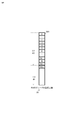
- the above storage space is managed by dividing it into a plurality of fixed-size storage areas called stripe blocks.
- FIG. 3 shows an example in which the RAID level of the RAID group 20 (representing a data redundancy method in the RAID technology and generally having RAID1 to RAID6 types) is RAID5.
- boxes such as “0”, “1”, “P” in the RAID group 20 in FIG. 3 represent stripe blocks, and the size of each stripe block in one RAID group 20 (hereinafter “ Called “stripe size” is the same.
- the stripe size for example, 64 KB, 256 KB, 512 KB or the like is used.
- a number such as “1” assigned to each stripe block is referred to as a “stripe block number”.
- the stripe block described as “P” in the stripe block is a stripe block in which redundant data is stored, and this is called a “parity stripe”.
- a stripe block in which numbers (0, 1 etc.) are written is a stripe block in which data (data which is not redundant data) written from a host device such as the host 2 is stored. This stripe block is called “data stripe”.
- the stripe block located at the head of FMPK # 3 (200-3) is the parity stripe 301-3.
- the data stripe (stripe) positioned at the head of each FMPK 200 (FMPK # 0 (200-0) to FMPK # 2 (200-2)) is stored. Redundant data is generated by performing a predetermined operation (for example, exclusive OR (XOR) or the like) on the data stored in the blocks 301-0, 301-1 and 301-2).
- a predetermined operation for example, exclusive OR (XOR) or the like
- a parity stripe and a set of data stripes (for example, element 300 in FIG. 3) used to generate redundant data stored in the parity stripe are referred to as “strip lines”.
- strip lines a parity stripe and a set of data stripes used to generate redundant data stored in the parity stripe.
- each stripe block belonging to one stripe line has the same position in the storage space of the FMPKs 200-0 to 200-3 ( The stripe line is formed based on the rule that the address exists.
- the stripe block number described above is a number assigned to the data stripe, and is a unique number within the RAID group. As shown in FIG. 3, the DKC 10 assigns numbers 0, 1 and 2 to the data stripes located at the head of each FMPK 200 constituting the RAID group. . .
- the data stripe is managed by assigning a serial number.
- a data stripe whose stripe block number is n (n is an integer value of 0 or more) is referred to as “data stripe n”.
- the storage system 1 manages each storage device 200 (200 ') belonging to the RAID group by assigning a unique number within the RAID group. This unique number is called a “position number in the RAID group” or “position number”. Specifically, when the first stripe line in the RAID group includes data stripe 0 to data stripe k (k> 0), the storage device 200 in which the data stripe m (0 ⁇ m ⁇ k) is stored. The position number of (200 ′) is defined as “m”.
- the position number of the storage device 200 (200 ') in which the parity stripe is stored is determined as "k + 1". Further, in the case of a RAID configuration in which two parity stripes exist within one stripe line as in RAID 6, the position numbers of the two storage devices 200 (200 ′) in which the parity stripes are stored are “k + 1” and “k + 2”, respectively.
- the position numbers of the three storage devices 200 (200 ') in which the data stripes 0 to 2 in the leading stripe line 300 are stored are defined as 0, 1, and 2.
- the position number of the storage device 200 (200 ') in which redundant data (parity) in the same stripe line as the data stripes 0 to 2 is stored is determined to be 3.
- the DKC 10 provides one or more storage spaces called logical units (LU) to the host device such as the host 2.
- LU logical units
- the storage space of the RAID group is a storage space formed by arranging only data stripes in order from the data stripe 0 in the area in the RAID group shown in FIG.
- the DKC 10 can define a continuous area on the storage space of one RAID group as a logical unit.
- a plurality of logical units may be defined on the storage space of one RAID group, or the entire storage space of one RAID group may be defined as one logical unit.
- FIG. 4 shows an example in which two logical units (LU # 0, LU # 1) are defined in the storage space of the RAID group.
- LU # 0 is defined in the RAID group shown in FIG.
- the DKC 10 divides the data for three stripe blocks received together with the write command for each stripe block.
- the three pieces of data generated by the division are referred to as “data 0”, “data 1”, and “data 2”, respectively.
- the DKC 10 generates redundant data (parity) using the data 0 to data 2 and stores the data 0 to data 2 and the generated parity in different storage devices 200, respectively.
- LU # is defined in the RAID group shown in FIG. 3
- data 0 to data 2 and parity are stored in FMPK (200-0) to FMPK (200-3), respectively.
- the parity can be generated by calculating the exclusive OR (XOR) of data 0 to data 2. Parity calculation is performed using the parity calculation circuit 15 of the DKC 10. However, when the storage device 200 constituting the RAID group has a parity generation function such as the parity calculation circuit 205 as shown in FIG. 2, the parity may be generated using the parity generation function of the storage device 200. it can.
- the DKC 10 has three types of management information in the memory 14: a device management table, a RAID group management table (RG management table), and an LU management table.
- FIG. 5 shows an example of the device management table T1000.
- the device management table T1000 is a table for managing information about each storage device 200 (or 200 ') mounted in the storage system 1. Information of each storage device 200 (200 ') mounted in the storage system 1 is stored in each row in the device management table T1000 (hereinafter, the row in the table is referred to as "record").
- the record of the device management table T1000 includes device # (T1001), device type (T1002), affiliation RG # (T1003), device status (T1004), compression function support (T1005), parity operation function support (T1006), size ( T1007).
- the DKC 10 manages each storage device 200 (or 200 ′) mounted in the storage system 1 with a unique identification number, and this identification number is “device number” (or “device #”). be called.
- Device # (T1001) stores device # of storage device 200 (200 ').
- the device type (T1002) is an item for storing information about the type of the storage device 200 (200 ').
- the device type (T1002) stores either “FMPK” or “HDD” information.
- FMPK is stored in the device type (T1002) of a record
- “HDD” is stored, the record This indicates that the storage device managed by is HDD 200 ′.
- the affiliation RG # (T1003) will be described later.
- the device status (T1004) stores the state of the storage device. When “normal” is stored in the device status (T1004), this indicates that the storage device managed by the record is operating normally. When “blocked” is stored in the device status (T1004), this indicates that the storage device managed in the record is not operating (is blocked) due to a failure or the like. .
- failure recovery in progress (recovery source)” or “failure recovery in progress (recovery destination)” is stored in the device status (T1004)
- data recovery processing is performed for the RAID group to which the storage device managed by the record belongs. Indicates what is being done. Although details will be described later, for example, when a failure occurs in one storage device, a device that replaces the failed storage device in the data recovery process (hereinafter referred to as “spare device”) is prepared. To do.
- the DKC 10 stores “failure recovery in progress (recovery source)” in the device status (T1004) of the storage device in which the failure has occurred.
- the DKC 10 stores “failure recovery in progress (recovery destination)” in the device status (T1004) of the storage device to be a spare device. Then, the data stored in the storage device in which the failure has occurred is recovered, and the data is restored by writing to the spare device.
- the compression function support (T1005) and the parity calculation function support (T1006) information on whether or not the compression function is supported and whether the parity calculation function is supported is stored in the storage device managed by the record.
- “support” is stored in the compression function support (T1005), this means that the storage device managed by the record has the compression function, and “unsupported” is stored. Means that the storage device managed by the record does not have a compression function.
- the parity calculation function support (T1006) stores either “support” or “unsupported” information. If “support” is stored, the storage device managed by the record is It means that it has a parity operation function.
- Information stored in the compression function support (T1005) and the parity calculation function support (T1006) may be set by the administrator of the storage system 1 using the management terminal.
- the DKC 10 inquires whether each storage device has a compression function and / or a parity calculation function by issuing a command for inquiring the function of each storage device to each storage device.
- the DKC 10 may reflect the inquiry result to the compression function support (T1005) and the parity calculation function support (T1006).
- the size (T1007) stores the capacity of the storage device, specifically the size of the storage space provided to the DKC 10 by the storage device 200 (200 ').
- the information about the size of the storage space is information that can be acquired from the storage device 200 (200 ') when the DKC 10 issues a command for inquiring the size to the storage device 200 (200').
- the size of the storage space may be larger than the total size of the storage medium (for example, the FM chip 210) included in the storage device 200 itself.
- FIG. 6 shows an example of the RG management table T1100. Similar to the device management table T1000, information about a RAID group is stored in each of a plurality of records in the RG management table T1100.
- the DKC 10 manages each RAID group defined in the storage system 1 with a unique identification number, and this identification number is called “RAID group number” or “RG #”.
- a RAID group number (RG #) is stored in RG # (T1101).
- the belonging device # (T1102) stores the device # of the storage device 200 (200 ′) included in the RAID group.
- the DKC 10 stores RG # (T1101).
- "0", "0, 1, 2, 3, 4" are stored in the column of belonging device # (T1102) of the record with 0.
- the RG # (T1003) of each record in the device management table T1000 in FIG. 5 stores the RAID group number to which each storage device belongs.
- the storage system 1 manages each storage device 200 (200 ') belonging to the RAID group in association with a position number. Therefore, each FMPK 200 registered in the belonging device # (T1102) is associated with a position number (T1102 ').
- the FMPK 200 with device numbers 8 to 15 belongs to the RAID group (RG # (T1101) is 1) managed by the record T1100-1, but each FMPK 200 has a position number 0. Numbers 7 to 7 are associated.
- the RAID configuration (T1103) is an item in which information about the configuration of the RAID group is stored.
- the RAID configuration (T1103) includes at least a RAID level that represents a data protection method using RAID technology and the number of data stripes used when generating redundant data. Information on the number of parity stripes to be stored is stored.
- the RAID configuration (T1103) of the record T1100-1 is “RAID5 (3D + 1P)”. This is a RAID configuration in which the RAID level is 5, and one parity is generated from three data stripes. It represents something.
- the RG capacity (T1104) and stripe size (T1105) store the amount of data (size) and stripe size that can be stored in the RAID group, respectively.
- the capacity stored in the RG capacity (T1104) is the total size of all data stripes in the RAID group, and does not include the size of parity.
- a capacity including the size of the parity may be stored.
- the status of the RAID group (any state of “normal”, “failure recovery”, “failure recovery failure”) is stored.
- the meaning of the status of the RAID group is the same as that of the device status (T1004), and when “normal” is stored in the RG status (T1106), it indicates that the RAID group is operating normally. . If “failure recovery” is stored, it indicates that the RAID group recovery processing is being performed. If “failure recovery failure” is stored, the RAID group is blocked. It represents something.
- Compressed (T1107) and parity calculation (T1108) store “executed” or “unexecuted” information, respectively.
- execution is stored in the compression (T1107)
- the RAID group managed by the record performs data compression using the compression function of the storage device (FMPK200), and the compressed data is stored in the FMPK200.
- FMPK200 compression function of the storage device
- the parity calculation (T1108) it indicates that the parity stored in the RAID group managed by the record is calculated using the parity calculation function provided in the FMPK 200.
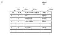
- FIG. 7 shows an example of the LU management table T1200. Similar to the device management table T1000, information about one LU is stored in each record in the LU management table T1200. Each LU has a unique identification number called a logical unit number (LUN), and the logical unit number of the LU is stored in LU # (T1201).
- LUN logical unit number
- the DKC 10 defines a continuous area in the RAID group as an LU.
- the LU management table T1200 stores the RG # (T1202) of the RAID group in which the LU is defined, the offset address (T1203) in the RAID group in which the LU is defined, and the LU size (T1204).
- the FMPK 200 manages the storage space (logical address space) provided to the DKC 10 in units of areas of a predetermined size called logical pages. In order to identify each logical page, each page is given a unique number. This number is called a “logical page number”. The logical page number of the logical page located at the head of the logical address space is 0, and successive logical pages are assigned consecutive numbers. As an example, the size of the logical page is 16 sectors (8 KB).
- the storage area existing in the FM chip 210 in the FMPK 200 is called a “physical page”.
- a physical page is a minimum unit of access (read, write) in the flash memory. Therefore, when the FM controller 201 reads / writes data from / to the FM chip 210, it reads / writes in units of physical pages.
- the FMPK 200 includes a plurality of FM chips 210, and each FM chip 210 has a plurality of physical pages. In the FMPK 200, a unique number is assigned to each physical page in all the FM chips 210. I manage. This number is called a “physical page number”. If the physical page number of the physical page in which the data to be accessed is stored is specified, the FM chip 210 in which the physical page exists and the position in the FM chip 210 can be uniquely specified.
- the physical page size and logical page size may be the same or different.
- the reason why the size is 256 bytes larger than the size of the logical page (8 KB) is that a DIF and ECC described later are added to each data.
- FMPK200 has a compression function.
- the FMPK 200 compresses and stores data
- the FMPK 200 performs compression in units of logical pages.
- data generated by compressing data on one logical page is referred to as a “compressed page”.
- the size of the compressed page is a multiple of 520 bytes, with a minimum of 520 bytes and a maximum of (520 ⁇ 16) bytes.
- Compressed pages will be smaller than physical pages due to compression. Therefore, a plurality of compressed pages can be stored in one physical page.
- One compressed page may be stored across a plurality of physical pages.
- the size of the compressed page described above is the size when no ECC is assigned.
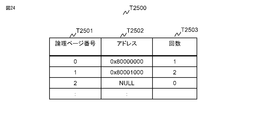
- FIG. 9 shows an example of the mapping table T2100 managed by the FMPK 200.
- Each row (record) stores information about each logical page.
- the record includes items of logical page number (T2101), physical page number (T2102), size (T2103), and offset (T2104).
- the mapping table T2100 is stored on the memory 202.
- the logical page number (T2101) stores the logical page number of the logical page managed by the record.
- the physical page number (T2102) stores the physical page number of the physical page to which the logical page managed by the record is mapped.
- the mapping table T2100 also manages information for specifying the area in the physical page where the compressed page is stored.
- the information is a size (T2103) and an offset (T2104).
- the offset (T2104) stores a relative address when the top address of the physical page is 0.
- the compressed page is stored in the area specified by the offset (T2104) and the size (T2103).
- a logical page with a logical page number of 1000 is mapped to a physical page with a physical page number (T2102) of 10, and this logical
- the page data (compressed page) is compressed to 2 KB, and the physical page number (T2102) is stored in an area of 2 KB starting from the position of 4 KB from the top of the 10th physical page. Represents.
- a record T2100-1 (a record with a logical page number T2101 of 1) represents an example in which a logical page is mapped to two physical pages.
- the logical page (logical page number T2101 is number 1) specified by the record T2100-1 is mapped to the physical page with the physical page number (T2102) numbered 500 and the physical page numbered 42.
- the physical page number (T2102) is an area of 1 KB size starting from the position of 7 KB from the top of the 500th physical page
- the physical page number ( T2102) is stored across an area of size 1 KB starting from the position of 0 KB from the top of the 42nd physical page.
- a record T2100-0 represents an example of a record when a physical page is not allocated to a logical page (T2101 is number 2) (physical page number T2102 is NULL).
- the FMPK 200 maps a physical page to a logical page for the first time when access to the logical page is received from the DKC 10.
- FIG. 10 shows the contents of the state management table T2000.
- the state management table T2000 includes items of physical capacity T2001, data compression T2002, logical capacity T2003, connection DKC type T2004, belonging RAID group configuration T2005, RAID group position T2006, and belonging RAID group number (affiliation RG #) T2007. ing.
- the physical capacity T2001 is the total storage capacity of the FM chip 210 that the FMPK 200 has.
- the data compression T2002 stores either “Yes” or “No” information. If “Yes” is stored, the FMPK 200 compresses the write data from the DKC 10 and stores it in the FM chip 210. .
- the data compression T2002 is set such that the DKC 10 (or the administrator) sets “present” or “not present” when the DKC 10 uses the FMPK 200 to define a RAID group.
- the logical capacity T2003 is the capacity of the address space provided by the FMPK 200 to the DKC 10.
- the value of the physical capacity T2001 and the value of the logical capacity T2003 are equal.
- the value of the logical capacity T2003 is larger than the physical capacity T2001.
- the FMPK 200 stores a temporary value (for example, a value that is eight times the physical capacity T2001) in the logical capacity T2003.
- a storage space having a size equal to the temporary value is provided.
- the size of the logical capacity T2003 may be reduced. Conversely, if the FMPK 200 determines that a larger amount of data than the logical capacity T2003 can be stored because the data size has become smaller than expected due to compression, processing such as increasing the size of the logical capacity T2003 may be performed. .
- connection DKC type T2004 stores the type (model name, etc.) of the storage system 1 to which the FMPK 200 is connected.
- information about the type of the storage system 1 is passed from the DKC 10 to the FMPK 200.
- the FMPK 200 stores the passed information in the connection DKC type T2004.
- the belonging RAID group configuration T2005, the RAID group internal position T2006, and the belonging RG # (T2007) are information about the RAID group to which the FMPK belongs, and the RAID configuration T1003 and the belonging device # (T1102) stored in the RG management information T1100. , Information similar to the information of RG # (T1101) is stored. These pieces of information are notified from the DKC 10 to the FMPK 200 when the DKC 10 uses the FMPK 200 to define the RAID group.
- the storage controller (DKC) 10 adds verification information that is error detection information, and stores the data and the verification information in the drive 121. To do.
- This verification information is one disk block (also called one sector) which is the minimum access unit when the host 2 accesses the logical unit.
- the size of one disk block (sector) is generally 512 bytes. In the storage system 1 of this embodiment, the size of one disk block (sector) is 512 bytes).
- this verification information is referred to as DIF.
- processing for adding further verification information to the data is also performed in the FMPK 200.
- the verification information added to the data by the DKC 10 is called “DKC-DIF”
- the verification information added to the data by the FMPK 200 in the FMPK 200 is called “PK-DIF”.
- DIF the verification information added to the data by the FMPK 200 in the FMPK 200
- ECC the verification information added to the FMPK 200 in the FMPK 200.
- FIG. 11 is a conceptual diagram showing a process in which DIF is added to write data from the host 2.
- the DKC (storage controller) 10 adds a DKC-DIF 511 before transmitting the write data to the FMPK 200.
- Write data 501 represents the state of the write data (the state in which the DKC-DIF 511 is added) immediately before being transmitted to the FMPK 200.
- the DKC 10 adds a DKC-DIF 511 for each sector (512 bytes), and transmits the write data 501 with the DKC-DIF 511 added to the FMPK 200.
- the data flow in the FMPK 200 will be described.
- the data (write data 501) arriving at the SAS-CTL 206 is passed to the compression / decompression circuit 204.
- Write data 502 represents the format of data passed from the SAS-CTL 206 to the compression / decompression circuit 204.
- the SAS-CTL 206 delivers data to the compression / decompression circuit 204, a PK-DIF 521 is added for each write data of one sector.
- the size of the DKC-DIF 511 attached to the data of one sector is 8 bytes.
- the DKC-DIF 511 includes a CRC (Cyclic Redundancy Check), a RAID group number, a sequence number, and address information.
- CRC is information generated by performing a predetermined operation on the data 510.
- the SAS-CTL 206 receives the write data 501 to which the DKC-DIF 511 is added from the DKC 10, it performs a predetermined operation on the data 510 to calculate a CRC. Then, it is determined whether the calculated CRC matches the CRC in the DKC-DIF 511 (hereinafter, this determination is referred to as “CRC check”). If they do not match, it means that the data content has been changed due to a failure or the like in the process of transferring data from the DKC 10 to the SAS-CTL 206. For this reason, if they do not match, an error is returned to the DKC 10 and the write processing of the write data 501 is interrupted.
- the address information is an address in the logical storage space on the FMPK 200 in which the data 510 is written (or a part of the address is included in the address information. For example, when the address exceeds 4 bytes, the lower 4 bytes of the address Only used as address information).
- the SAS-CTL 206 receives the write data 501 to which the DKC-DIF 511 is added from the DKC 10, it also receives a command (so-called WRITE command) instructing to store the write data 501 in the FMPK 200. Since the WRITE command also includes address information in the logical storage space on the FMPK 200 that is the write destination of the data 510, the SAS-CTL 206 is included in the address information included in the DIF and the WRITE command. It is determined whether the address information matches. If they do not match, the FMPK 200 returns an error to the DKC 10 and interrupts the write processing of the write data 501.
- the RAID group number is a RAID group number (RG #) to which the FMPK 200 to which the data 510 is written belongs.
- the FMPK 200 has previously received information on the number of the RAID group to which the FMPK 200 belongs from the DKC 10. Therefore, when the SAS-CTL 206 receives the write data 501 to which the DKC-DIF 511 is added from the DKC 10, it can compare the RAID group number included in the DKC-DIF 511 with the RAID group number received in advance. it can. If they do not match, the FMPK 200 returns an error to the DKC 10 and interrupts the write processing of the write data 501.
- the sequence number is a kind of serial number.
- consecutive sequence numbers are stored in the DKC-DIF 511 attached to the adjacent data 510.
- the sequence number 0 is stored in the DKC-DIF 511 assigned to the first data 510
- the sequence number 1 is stored in the DKC-DIF 511 assigned to the next data 510. Is stored. Therefore, when data of a plurality of consecutive sectors is written (or read), the SAS-CTL 206 determines whether the sequence numbers of adjacent sectors are consecutive numbers. If the serial number is not assigned, the FMPK 200 returns an error to the DKC 10 and interrupts the write processing of the write data 501.
- the PK-DIF 521 includes a CRC calculated from the data.
- the CRC included in the PK-DIF 521 is a CRC calculated from 520-byte data composed of the data 510 and the DKC-DIF 511.
- the compression / decompression circuit 204 performs data compression. As described above, the compression is performed for each data of one logical page. At the time of compression, the DKC-DIF 511 and the PK-DIF 521 added to the data 510 are also compressed. That is, the compression / decompression circuit 204 compresses 16 sets of “data 510, DKC-DIF 511, and PK-DIF 521” together. The compression / decompression circuit 204 generates the compressed data so that the size is a multiple of 520 bytes.
- the compression / decompression circuit 204 adds the PK-DIF 531 to the compressed data 530-0.
- the PK-DIF 531 is attached for each 520-byte data (compressed data). Similar to the PK-DIF 521, the PK-DIF 531 includes a CRC calculated from the data (compressed data 530-0).
- the compression / decompression circuit 204 calculates a CRC from the data 510 and the DKC-DIF 511 before performing compression. Then, it is determined whether the calculated CRC matches the CRC included in the PK-DIF 521. If they do not match, an error is returned to the DKC 10 and the write processing of the write data 501 is interrupted.
- the compressed data 530-0 and its PK-DIF 531 generated by the compression / decompression circuit 204 are written into the FM chip 210 via the FM-IF 207.
- the FM-IF 207 checks the CRC included in the PK-DIF 531. The check method is the same as that performed by the compression / decompression circuit 204. CRC is calculated from the compressed data 530-0, and it is determined whether the calculated CRC matches the CRC included in the PK-DIF531. If they do not match, an error is returned to the DKC 10 and the write processing of the write data 501 is interrupted.
- the FM-IF 207 removes the PK-DIF 531 attached to the compressed data 530-0. Then, another error check code is generated from the compressed data 530-0. This error check code is called “ECC”.
- ECC error check code
- the ECC 541 is provided for each 520-byte compressed data 530-0, as in the PK-DIF 531.
- the FM-IF 207 writes the compressed data 530-0 assigned with the ECC 541 to the FM chip 210.
- the FM-IF 207 reads the compressed data 530-0 to which the ECC 541 is added from the FM chip 210, and checks the ECC 541 (compares the ECC calculated from the compressed data 530-0 with the ECC 541). Thereafter, the ECC 541 is removed from the compressed data 530-0, the PK-DIF 531 is added, and the compressed data 530-0 to which the PK-DIF 531 is added is passed to the compression / decompression circuit 204.
- the compression / decompression circuit 204 checks the CRC included in the PK-DIF 531, and then decompresses the compressed data 530-0 to generate a set (one or a plurality) of “data 510, DKC-DIF 511, and PK-DIF 521”. .
- the SAS-CTL 206 checks the CRC included in the PK-DIF 521, Thereafter, the PK-DIF 521 is removed from the set of “data 510, DKC-DIF 511, and PK-DIF 521”, and the data 510 and DKC-DIF 511 are transferred to the DKC 10.
- the data flow described above is an example when the data is compressed by the compression / decompression circuit 204.
- the FMPK 200 can store the data in the FM chip 210 without compressing the data.
- the data 510 to which the PK-DIF 521 is added by the SAS-CTL 206 is passed to the FM-IF 207 without passing through the compression / decompression circuit 204.
- the FM-IF 207 checks the CRC included in the PK-DIF 521. The checking method is the same as described above.
- the FM-IF 207 removes the PK-DIF 521 from the data 510 to which the PK-DIF 521 is added, generates an ECC, and adds it.
- the ECC here is generated from 520-byte data composed of data 510 and DKC-DIF 511. Then, the data 510 with the ECC added and the DKC-DIF 511 are stored in the FM chip 210.
- the information included in the DKC-DIF 511, PK-DIF 521, and PK-DIF 531 described above is an example, and verification information other than that described above may be included.
- the DKC-DIF 511 is information added by the DKC 10 to which the FMPK 200 is connected
- the format of the DKC-DIF 511 may differ depending on the type (model) of the DKC 10.
- the length of CRC or address information may vary depending on the type of DKC 10.
- the address information, sequence number, and CRC arrangement order in the DKC-DIF 511 may differ depending on the type of the DKC 10.
- the FMPK 200 grasps information about the DKC-DIF format of each model (DKC) (such as a location where CRC and address information are stored). Further, by receiving DKC type (model) information from the connected DKC, the storage location of the CRC, address information, sequence number, and RAID group number can be recognized.
- DKC model
- the FMPK 200 receives a command from a higher-level device such as the DKC 10, and performs processing (data read, write, etc.) according to the content of the instruction information (parameter) included in the received command.
- the FMPK 200 supports a read command for instructing data reading and a write command for instructing data writing, as well as known storage devices such as SSDs and HDDs, but also supports other commands.
- the contents of commands used in the data recovery process performed in the present embodiment will be described.
- description will be made on the assumption that the issuing device that issues a command to the FMPK 200 is the DKC 10.
- This command is a command for instructing the command issuer such as the DKC 10 to return the read data in a compressed state.
- the parameters included in the compressed Read command will be described with reference to FIG.
- the compressed read command 3000 includes parameters of an opcode 3001, a read start offset 3002, a read size 3003, a buffer address 3004, and a transfer size 3005.
- the operation code (Opcode) 3001 is information included in all commands supported by the FMPK 200 (however, the content of the information included in the operation code 3001 varies depending on the command).
- the FMPK 200 stores the operation code 3001 of the received command. By referring, the type of the received command is identified. Of course, the opcode 3001 included in the compressed read command 3000 stores information that can be identified as the compressed read command.
- the Read start offset 3002 and the Read size 3003 are information for specifying an area in the logical address space on the FMPK 200 in which data (read target data) that the DKC 10 wants to read is stored.
- the read start offset 3002 specifies the start address of the logical address space area on the FMPK 200 where the read target data is stored
- the read size 3003 specifies the size of the read target data.
- a logical block address (LBA) is used as information for specifying an address.
- a logical page number may be used as information for specifying an address.
- the read size 3003 specifies the number of sectors. However, as another embodiment, other units (for example, the number of logical pages, the number of bytes, etc.) may be specified.
- the read size 3003 specifies the data size at the time of non-compression regardless of whether the data is compressed and stored in the FMPK 200.
- the buffer address 3004 and the transfer size 3005 are information for specifying the transfer destination area (the start address of the area and the size of the area) of the read target data.
- the buffer address The address 3004 designates the address of the buffer 131.
- the FMPK 200 When the FMPK 200 receives the compressed Read command 3000 from the DKC 10, the FMPK 200 transfers the compressed read data to the DKC 10 (transfers it to the area on the buffer 131 specified by the buffer address 3004 and the transfer size 3005 of the DKC 10), and response information. Return to DKC10.
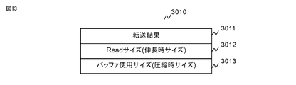
- the response information includes information indicating whether or not the processing related to the received command has been normally performed, and information about the size. The format of response information for the compressed Read command 3000 will be described with reference to FIG.
- the response information to the compressed read command 3000 includes a transfer result 3011, a read size 3012, and a buffer use size 3013.
- the transfer result 3011 includes information of “success” or “error”. When the transfer result 3011 is “success”, it means that the processing related to the compressed read command 3000 has been normally performed. .
- the read size 3012 stores the size of the read target data (when not compressed). In principle, the same value as the read size 3003 of the compressed read command 3000 is stored. In the buffer use size 3013, the size of the read data in the compressed state transferred to the DKC 10 is stored.
- the compressed copy write command 3100 includes parameters of an opcode 3101, a write start offset 3102, a write size 3103, a transfer source address 3104, and a transfer size 3105.
- the operation code (Opcode) 3101 includes information for the FMPK 200 to identify the type of the received command as described in the description of the compressed Read command.
- the write start offset 3102 and the write size 3103 are information for specifying the write destination area of the write target data.
- the write start offset 3102 is a logical address (provided by the FMPK 200) that is the write destination of the write target data.
- the space start address is the write size 3103, and the write target data size is specified. Note that when the compressed copy write command 3100 is issued, the compressed data is transmitted from the DKC 10 to the FMPK 200.
- the write start offset 3102 and the write size 3103 specified here are used to store write data when not compressed. Area (area on the logical address space) is designated.
- the transfer source address 3104 and the transfer size 3105 are information for specifying an area in which the compressed write target data to be transferred to the FMPK 200 is stored. Normally, when the DKC 10 issues the compressed copy write command 3100 to the FMPK 200, the write target data is stored in the buffer 131. For this reason, the source address 3104 and the transfer size 3105 specify the start address of the area where the write target data in the compressed state in the buffer 131 is stored and the size of the write target data in the compressed state, respectively.
- the response information to the compressed copy write command 3100 includes only the transfer result 3011 as shown in FIG.
- the transfer result 3011 is the same as the transfer result 3011 included in the response information for the compressed Read command 3000. That is, “success” or “error” information is included.
- the transfer result 3011 is “successful”, it means that the processing related to the compressed copy write command 3100 has been normally performed.
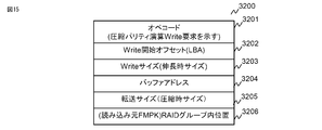
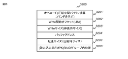
- the compressed parity calculation write command 3200 includes parameters of an opcode 3201, a write start offset 3202, a write size 3203, a buffer address 3204, a transfer size 3205, and a RAID group position 3206.
- the operation code (Opcode) 3201 includes information for the FMPK 200 to identify the type of the received command.
- the write start offset 3202 and the write size 3203 are information for specifying the storage destination of data generated by performing the parity calculation (hereinafter referred to as a parity calculation result).
- the write start offset 3202 includes the parity calculation.
- the start address of the logical address space (provided by the FMPK 200), which is the result writing destination, is designated as the write size 3203, and the size of the parity operation result is designated.
- the write start offset 3202 and the write size 3203 specified here specify an area for storing the parity calculation result at the time of non-compression (area on the logical address space). .
- the buffer address 3204 and transfer size 3205 are the same as the transfer source address 3104 and transfer size 3105 of the compressed copy write command. That is, it is information for specifying the area where the write target data is stored. Normally, when the DKC 10 issues the compressed parity operation write command 3200 to the FMPK 200, the write target data is stored in the buffer 131. Therefore, the buffer address 3204 and the transfer size 3205 respectively specify the top address of the area on the buffer 131 in which the write target data is stored and the size of the write target data data (compressed size).
- the position number of the FMPK 200 where the write target data (in a compressed state) was originally stored is stored.
- the RAID group 20 shown in FIG. 3 will be described as an example.
- the DKC 10 stores the compressed data in the RAID group position 3206.
- a compressed parity operation write command storing the stored FMPK # 0 position number (that is, No. 0) is created, and the created command is issued to FMPK # 3.
- the response information for the compressed parity operation write command 3200 is the same as the response information for the compressed copy write command 3100. That is, as shown in FIG. 16, only the transfer result 3011 is included.
- the FMPK 200 in addition to the compressed read command, compressed copy write command, and compressed parity calculation write described above, is a command for setting information in the state management table T2000 (hereinafter referred to as an “information setting command”). ), A failure part diagnosis command of the FMPK 200 is also prepared. Since the command for setting information in the state management table T2000 only transmits information to be set in the state management table T2000, such as the belonging RAID group configuration (T2005), the details are omitted. Further, the failure part diagnosis command of the FMPK 200 is a command issued by the DKC 10 to the FMPK 200 in which a failure has occurred. The FMPK 200 that has received this command displays a list of logical pages that the DKC 10 cannot access (read or write) because a failure has occurred in the storage address space provided by the FMPK 200 to the DKC 10. Return to the command issuer (DKC10).
- DKC10 command issuer
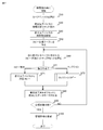
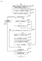
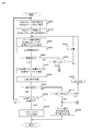
- FIG. 17 is a flowchart showing the overall flow of data recovery processing executed by the DKC 10.
- the DKC 10 accesses (reads or writes) the FMPK 200 and the access fails (an error is returned)
- the DKC 10 starts the data recovery process of FIG.
- the memory 14 of the storage system 1 stores a program for executing data recovery processing (data recovery program), and the data recovery processing is executed by the processor 11 executing this data recovery program.
- the spare device is selected first.
- the processor 11 refers to the device management table T1000 and selects one FMPK 200 whose RG # (T1003) is “unallocated (spare)” (S20).
- the selected FMPK 200 is referred to as a “recovery destination device” or a “spare device”.
- an FMPK 200 equivalent to the FMPK 200 in which a failure has occurred hereinafter, this FMPK 200 is referred to as a “recovery source device” is selected.
- the FMPK 200 having the same contents of the compression function support T1005, the parity operation function support T1006, and the size T1007 is selected.
- the same number as the RAID group number to which the failed FMPK 200 belongs is stored in the affiliation RG # (T1003). Recovery destination) ". Further, “failure recovery (recovery source)” is stored in the device status T1004 of the record for the FMPK 200 in which the failure has occurred.
- the FMPK 200 whose device # is No. 4 hereinafter, the FMPK 200 whose device # is x (x is an integer value) is selected as “FMPK # x”) is selected as the recovery destination device
- the device management table T1000 Will be in the state shown in FIG.
- the first method is a method of reading data from the recovery source device and writing (copying) the data to the recovery destination device.
- the first method is a method of reading data from the recovery source device and writing (copying) the data to the recovery destination device.
- the first method is a method of reading data from the recovery source device and writing (copying) the data to the recovery destination device.
- the entire storage area is rarely inaccessible. Therefore, there may be an area accessible (readable) from the DKC 10 in the storage space of the recovery source device.
- data recovery is performed by reading data from this readable area and copying it to the recovery destination device.
- This method is hereinafter referred to as “copy recovery”.
- this method cannot be used for an area inaccessible (unreadable) from the DKC 10.
- data is read from each device in the RAID group to which the recovery source device belongs, and is stored in the recovery source device by performing a predetermined operation using each read data. It is a method to regenerate the data. This method is hereinafter referred to as “collection” or “collection copy”. As a data regeneration method, for example, an operation described in Patent Document 1 may be performed. When performing collection, the storage system 1 according to the present embodiment can employ three methods, which will be described later.
- the processor 11 transmits an information setting command to the recovery destination device, so that the status management table T2000 of the recovery destination device includes the belonging RAID group configuration (T2005), the position in the RAID group (T2006), and the data compression. (T2002) is set.
- the belonging RAID group configuration (T2005) the same RAID configuration (information stored in T1103 in the RG management table T1100) as that of the RAID group to which the recovery destination device belongs is set.
- the RAID group internal position (T2006) the RAID group internal position (information stored in T1102 in the RG management table T1100) of the FMPK 200 in which the failure has occurred is set.
- data compression T2002
- the same information as the FMPK 200 in which a failure has occurred is set.
- the processor 11 issues a failure location diagnosis command to the recovery source device.
- the recovery source device that has received this command returns a diagnosis result to the processor 11.
- the diagnosis result includes a list of inaccessible logical pages.
- the copy management table is a table that collects information that should be grasped when the processor 11 performs data recovery processing.
- the contents of information managed in the copy management table T1500 will be described with reference to FIG.
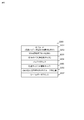
- the copy management table T1500 includes a failure RG # (T1501), a recovery source device (T1502), a recovery destination device (T1503), a collection method (T1504), a recovery device capacity (T1505), a copy method bitmap (T1506), a recovery The item of completed offset (T1507) is included.
- the failure RG # (T1501) stores the RG # of the RAID group that is the recovery target by the data recovery process.
- the recovery source device (T1502) and the recovery destination device (T1503) store the device # of the recovery source device and the device # of the recovery destination device, respectively.
- the collection method (T1504) stores information about the collection method implemented in the data recovery process. In the storage system 1 according to the present embodiment, the following three collection methods can be selected.
- the first method (hereinafter referred to as “method 1”) is the same as the collection method implemented in a known storage device. Specifically, the DKC 10 reads data from a normal FMPK 200 other than the recovery source FMPK 200 in the RAID group, and stores the data from the read data in the recovery source device using the parity calculation circuit 15 in the DKC 10. Regenerate the data. The DKC 10 writes the regenerated data to the recovery destination.
- the second method (hereinafter referred to as “method 2”) is a method that can be applied when the recovery destination FMPK 200 has a parity operation function, and is also disclosed in Patent Document 1.
- the DKC 10 reads data from a normal FMPK 200 other than the recovery source FMPK 200 in the RAID group, and transmits the read data to the recovery destination FMPK 200.
- the recovery destination FMPK 200 regenerates the data by calculating the parity from the data transmitted from the DKC 200 using its own parity calculation function (parity calculation circuit 205).
- parity calculation circuit 205 since the method 1 and the method 2 are publicly known methods, description thereof is omitted in this embodiment.
- the third method (hereinafter referred to as “method 3”) is a method applicable when the recovery destination FMPK 200 has a parity calculation function and a compression function.
- method 3 is a method applicable when the recovery destination FMPK 200 has a parity calculation function and a compression function.
- description will be made on the assumption that data restoration by method 3 is performed. Therefore, the specific contents of method 3 will also be described in the course of explaining the flow of processing after FIG.
- One of “method 1”, “method 2”, and “method 3” described above is stored in the collection method (T1504). Whether “method 1”, “method 2”, or “method 3” is stored is determined by whether or not the FMPK 200 belonging to the data recovery target RAID group has a parity calculation function and a data compression function. Is done.
- the processor 11 sets “method 3” in the collection method (T1504).
- the processor 11 sets “method 2” in the collection method (T1504).
- the processor 11 sets “method 1” as the collection method (T1504).
- the DKC 10 prepares a bit map having a size of n bits as a copy method bitmap (T1506).
- the k-th bit (1 ⁇ k ⁇ n) of the copy method bitmap (T1506) indicates whether collection is performed for the k-th logical page in the logical address space of the recovery source FMPK 200.
- 1 is stored in the k-th bit of the copy method bitmap (T1506) (that is, k).
- the second logical page is recovered by collection data).
- the processor 11 determines the next process to be performed based on the contents of the bitmap.
- the address of the logical address space where the data recovery is completed is stored.
- a logical page number is used as an address stored in the recovery completed offset (T1507).
- other address information for example, LBA may be used.
- data recovery is performed in order from the start address (logical page with logical page number 0) of the logical space of the recovery source device. Therefore, in S50, the processor 11 stores 0 as an initial value in the recovery completed offset (T1507). When the data recovery for one logical page is completed, the processor 11 adds the page number (1) of the logical page for which the data recovery is completed to the recovery completed offset (T1507).
- the processor 11 causes the failure RG # (T1501), the recovery source device (T1502), the recovery destination device (T1503), the collection method (T1504), the recovery device capacity (T1505), the copy method bitmap (in the copy management table T1500).
- T1506) information is stored in the recovery completed offset (T1507). If a failure occurs in the FMPK 200 with the device number # 1 belonging to the RAID group with the RAID group number 0, the processor 11 sets 0 to the failure RG # (T1501) and 1 (FMPK # 1) to the recovery source device (T1502). ). When FMPK # 4 is selected as the recovery destination device, 4 (FMPK # 4) is stored in the recovery destination device (T1503).
- RG # 0 When the state of the RAID group (RG # 0) in which the failure has occurred is the one shown in FIG. 6, and the attribute of FMPK # 4 that is the recovery destination device (particularly compression function support T1005, parity operation function support T1006) Is the case shown in FIG. In this case, RG # 0 performs compression, and performs parity generation using the parity calculation function of FMPK200. FMPK # 4 supports both a compression function and a parity calculation function. Therefore, the processor 11 stores “method 3” as the collection method T1504.
- the recovery device capacity (T1505) stores the size of the recovery destination device.
- the copy method bitmap (T1506) is set based on the result of diagnosis in S40.
- 1 is stored in the kth bit of the copy method bitmap (T1506). If the kth logical page is accessible, 0 is stored in the kth bit of the copy method bitmap (T1506).
- the processor 11 initializes the restoration completed offset (T1507) (stores 0).
- the processor 11 selects the (restoration completed offset (T1507) +1) -th bit of the copy method bitmap (T1506), and in S70, determines a logical page recovery method for performing data recovery. If the selected bit is 0 (S70: copy recovery), copy recovery is performed (S71). If the selected bit is 1 (S70: collection), collection copy is performed (S72). The processing contents of S71 and S72 will be described later.
- the processor 11 When the processing of S71 or S72 is completed, the processor 11 performs the processing of S80.
- the processor 11 adds the size of the recovered data to the recovery completed offset (T1507). In the case of recovery in units of logical pages, 1 is added.
- the processor determines whether the data recovery is completed for all areas of the recovery source device. The determination of data restoration completion is obtained from the restoration device capacity (T1505) by obtaining the terminal logical page number of the restoration source device (dividing the restoration device capacity (T1505) by the logical page size) and indicated by the restoration completed offset (T1507). It may be determined whether the logical page number has reached the terminal logical page number of the recovery source device.
- the processor 11 performs the processing after S60 again.
- the processor 11 updates the management information. Specifically, the device status (T1004) is changed to “blocked” for the record of the recovery source device in the device management table T1000. Further, the device status (T1004) is changed to “normal” for the record of the recovery destination device in the device management table T1000. Further, the processor 11 changes the information of the belonging device (T1102) in the RG management table T1100. Specifically, the device # of the recovery source device is deleted from the information registered in the belonging device (T1102), and the device # of the recovery destination device is added (S100).
- the above is the overall flow of data recovery processing.
- the unit of data recovery is not restricted to a logical page.
- Data recovery may be performed in a unit larger than the logical page (for example, an integer multiple of the logical page), or data recovery can be performed even if data recovery is performed in a unit smaller than the logical page.
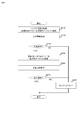
- the processor 11 secures an area for one logical page as an area for storing read data in the buffer 131.
- a compressed Read command is issued to the recovery source device (S210).
- a value obtained by converting the recovery completed offset T1507 (logical page number) to LBA is set in the Read start offset 3002.
- the read size 3003 uses a size for one logical page. For the buffer address 3004 and the transfer size 3005, the information of the area on the buffer 131 previously secured is used.
- the processor 11 After issuing the compressed Read command, the processor 11 receives response information for the compressed Read command from the recovery source device (S220). When the transfer result 3011 included in the response information is “error” (S230: NO), the processor 11 performs a correction copy (S280) and ends the process. Details of processing performed in the collection copy will be described later.
- the transfer result 3011 included in the response information is “successful” (S230: YES)
- the data read in S210 and S220 is written to the recovery destination device.
- the parameters of the compressed copy write command issued here that is, the write start offset 3102, write size 3103, and transfer source address 3104 are the parameters of the compressed read command issued in S210, that is, the read start offset 3002, read.
- the same value as the size 3003 and the buffer address 3004 is designated.
- the value of the buffer use size 3013 included in the response information received in S220 is designated as the transfer size 3105 of the compressed copy write command.
- the processor 11 receives response information for the compressed copy write command from the recovery destination device. If the transfer result 3011 included in the response information is “success” (S270: YES), the process is terminated. When the transfer result 3011 included in the response information is “error” (S270: NO), the processor 11 performs a correction copy (S280) and ends the process.
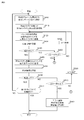
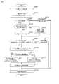
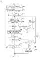
- the processor 11 selects one normal FMPK 200 from among the FMPKs 200 that have not yet performed the processing after S410 in the recovery target RAID group (S400). Subsequently, variables r and w are prepared, and initialization is performed by substituting 0 for both variables (S410). Note that the variable r is used to record the number of times of retry when data reading from the FMPK 200 fails. The variable w is used for recording the number of times of retry when data writing to the recovery destination device fails.
- the processor 11 secures an area for one logical page in the buffer 131 as an area for storing read data, and further issues a compression Read command to the FMPK 200 selected in S400.
- the contents specified as the parameter of the compressed Read command are the same as those specified in S210.
- the processor 11 receives response information from the FMPK 200 that has issued the compressed Read command.
- the transfer result 3011 included in the response information is “error” (S440: NO)
- the processor 11 performs the process of S450.
- the transfer result 3011 included in the response information is “success” (S440: YES)
- the processor 11 executes the process of S480.
- the processor 11 determines whether the variable r is greater than or equal to a certain value (S450). If the variable r is not yet greater than a certain value (S450: NO), 1 is added to r (S460), and the process of S420 is executed again. If the variable r is greater than or equal to a certain value (S450: YES), the processor 11 performs the process of S540. In S540, the RAID group status (RG status T1106) is changed to “failure recovery failure”, and the data recovery processing is interrupted. In addition, the fact that data recovery has failed is displayed on the management terminal. Alternatively, the host 2 may be notified that data recovery has failed.
- the processor 11 issues a compressed parity operation write command to the recovery destination device, thereby returning the data read in S420 and S430 to the recovery destination device. Is written (S480).
- the write start offset 3202, write size 3203, and buffer address 3204 are the parameters of the compressed read command issued in S420, that is, the read start offset 3002, read size, respectively.
- the same value as 3003 and buffer address 3004 is designated.
- the transfer size 3205 specifies the value of the buffer usage size 3013 included in the response information received in S430.
- the RAID group internal position 3206 can be identified by referring to the position number of the FMPK 200 selected in S400 (that is, the FMPK 200 that issued the compression Read command in S420) (position number (T1102 ′) in the RG management table T1100). ) Is specified.
- the processor 11 receives response information for the compressed parity operation write command from the recovery destination device. If the transfer result 3011 included in the response information is “success” (S500: YES), it is determined whether the processes of S410 to S500 have been performed for all normal FMPKs 200 constituting the RAID group (S550). If the process is completed for the normal FMPK 200 (S550: YES), the process ends. If there is an FMPK 200 that has not yet been subjected to the processing of S410 to S500 among all normal FMPKs 200 constituting the RAID group (S550: NO), the processor 11 performs the processing after S400 again.
- the processor 11 determines whether the variable w is greater than or equal to a certain value (S510), and if the variable w is not yet greater than a certain value (S510: NO), 1 is added to w (S520), and the process of S420 is executed again. If the variable w is greater than or equal to a certain value (S510: YES), the processor 11 performs the process of S540. In S540, the RAID group status (RG status T1106) is changed to “failure recovery failure”, and the data recovery processing is interrupted.
- the processing described above is data recovery processing for a RAID group in which the number of parity stripes in one stripe line is 1. Therefore, in S550, the processing in S410 to S500 is performed for all normal FMPKs 200 constituting the RAID group. It is determined whether or not On the other hand, when data recovery processing is performed for a RAID group (for example, RAID 6 as an example) in which n data stripes and a plurality of (for example, two in the case of RAID 6) parity stripes exist in one stripe line, in S550, It may be determined whether the processing of S410 to S500 has been performed for n FMPKs 200.
- RAID group for example, RAID 6 as an example
- the above is the flow of processing performed by the DKC 10 in the data recovery processing.
- a flow of processing executed by the FMPK 200 when the DKC 10 issues a command such as a compressed Read command to the FMPK 200 will be described.
- the processor 203 executes a command processing program stored in the memory 202 of the FMPK 202, so that processing related to the command is performed.
- the processor 203 prepares variables u and c, and initializes these variables (substitutes 0) (S1020).
- the variable u is mainly used for calculating the Read size 3012 included in the response information returned from the FMPK 200 to the DKC 10, and the variable c is used for calculating the buffer usage size 3013.
- the processor 203 calculates the address on the FM chip 210 (more precisely, the physical page number of the physical page and the offset within the physical page) in which the read target data specified by the compressed Read command is stored. .
- the logical page number is calculated from the address calculated by adding the value of the variable u to the Read start offset 3002 included in the parameter of the compressed Read command.
- the mapping table T2100 the physical page number (T2102), physical page offset (T2104), and size (T2103) of the physical page to which the calculated logical page number is mapped are obtained.
- the processor 203 reads data from an area (an area on the FM chip 210) specified by the physical page number (T2102), the physical page offset (T2104), and the size (T2103) obtained in S1030 (S1040). .
- the ECC stored in the FM chip 210 is appended with ECC for every 520 bytes of data.
- the FM-IF 207 checks data using ECC. If no error occurs in the data check (when the ECC attached to the data matches the ECC calculated from the data), the FM-IF 207 determines that every 520 bytes of data. Remove the attached ECC.
- the FM-IF 207 creates a PK-DIF for every 520 bytes of data and appends it to the data, and stores the data with the PK-DIF added in the memory 202. Thereafter, the processor 203 is notified of the successful reading.
- the minimum access (read, write) unit of the FM chip 210 is a physical page
- data is read in physical page units in S1040. Therefore, when one logical page is stored across multiple physical pages, the logical page is stored in a physical page in a compressed state, and data of another logical page is stored in the physical page.
- information other than the logical page to be accessed (or the compressed page in which the logical page data is compressed) is also read. In this case, after reading the physical page data and storing it in the memory 202, information other than the logical page to be accessed is deleted from the memory 202.
- the FM-IF 207 informs the processor 203 that the reading has failed. Notice.
- the processor 203 When the processor 203 receives a reading failure from the FM-IF 207 (S1050: NO), the processor 203 creates response information to be returned to the DKC 10 (S1160).
- the response information created here is response information in which “error” is stored in the transfer result 3011. Then, the processor 203 returns the created response information to the DKC 10 (S1150), and ends the process.
- the processor 203 determines whether or not the read data is compressed. Whether or not the read data is compressed can be determined by referring to whether or not the size (T2103) obtained in S1030 is the same as the size of the logical page.
- the processor 203 uses the compression / decompression circuit 204 to compress the read data. In the compression / decompression circuit 204, after the data is compressed, PK-DIF is added to the compressed data and stored in the memory 202.
- the size of the read data compressed in S1070 (or the size of the read data read in S1040 when S1070 is not executed) is set as c ′.
- the processor 203 determines whether c + c ′ is equal to or smaller than the transfer size 3005 specified by the parameter of the compressed Read command. If c + c ′ exceeds the transfer size 3005 (S1080: NO), the processor 203 creates response information in which “success” is stored in the transfer result 3011 (S1140), and sends the created response information to the DKC 10 Returning (S1150), the process is terminated. When c + c ′ is equal to or smaller than the transfer size 3005 (S1080: YES), the processing after S1090 is performed.
- the variable c stores the total amount of transferred data in the buffer 131 of the DKC 10 when S1030 to S1070 have been executed several times so far.
- c ′ is the size of data to be transferred to the buffer 131 of the DKC 10 from now on. Therefore, when c + c ′ exceeds the transfer size 3005, if the data read in S1040 (or the data compressed in S1070) is transferred, the data exceeding the size of the area on the buffer 131 secured by the DKC 10 is transferred. It will be. Therefore, the FMPK 200 makes the determination in S1080 so that the amount of data returned to the DKC 10 does not exceed the transfer size 3005 specified by the parameter of the compressed Read command. As a general rule, when the DKC 10 issues a compressed Read command, an area of a larger size (an area having the same amount as the read data size at the time of expansion) is secured on the buffer 131.
- the processor 203 transfers the data read in S1040 (the data compressed in S1070 when S1070 is executed) to the buffer 131 of the DKC 10.
- the SAS-CTL 206 checks the PK-DIF attached to the data during the transfer process. If the check result is normal, the SAS-CTL 206 removes the PK-DIF attached to the data and transfers the data from which the PK-DIF has been removed to the DKC 10. If the check result is not normal, the response information including “error” in the transfer result 3011 is returned to the DKC 10 and the process is terminated.
- the processor 203 adds c ′ to the variable c (S1100).
- the processor 203 adds the size of the data read in S1040 (size at the time of non-compression) to the variable u.
- the data for a plurality of logical pages may be read out in the processes of S1030 and S1040, or the data may be read out in units unrelated to the logical page.
- the size of the read data (however, the uncompressed size) is added to the variable u.
- the processor 203 determines whether or not the variable u is less than the Read size 3003. If u is less than the Read size 3003 (S1120: YES), the processor 203 performs the processing from S1030 again. If u is not less than the Read size 3003 (S1120: NO), the processor 203 creates response information (S1140). The response information created here is obtained by storing “success” in the transfer result 3011, the value of the variable u in the read size 3012, and the value of the variable c in the buffer use size 3013. Thereafter, the processor 203 returns the response information to the DKC 10 and ends the processing.
- the processor 203 receives the write data (the write data from the area on the buffer 131 specified by the transfer source address 3104 and the transfer size 3105, which are parameters of the compressed copy write command). To get).
- the received write data is stored in the memory 202.
- the processor 203 uses the compression / decompression circuit 204 to decompress the write data, and also stores the decompressed data in the memory 202 (S1520).
- the compressed copy write command is used when the DKC 10 uses the compressed read command 3000 to store data (compressed state) read from the FMPK 200 in the FMPK 200. Therefore, the data to be written by the compressed copy write command arrives at the FMPK 200 in a compressed state.
- the processor 203 verifies the data using the DIF (DKC-DIF) (hereinafter, the verification using the DIF is referred to as “DIF check”). Data verification using DKC-DIF is called “DKC-DIF check”, and data verification using PK-DIF is called “PK-DIF check”. I do.
- the processor 203 verifies (checks) data using the PK-DIF and DKC-DIF added to the decompressed data (S1540).
- the PK-DIF check the CRC generated from the decompressed data is compared with the CRC included in the PK-DIF to determine whether or not they match.
- the following checks are mainly performed. a) Check whether the CRC generated from the decompressed data matches the CRC in the DKC-DIF added to the decompressed data. b) Check whether the write start offset 3102 included in the parameter of the compressed copy write command (or the compressed parity operation write command) matches the address information included in the DKC-DIF. c) Check whether the RG # (T2007) stored in the status management table T2000 of the FMPK 200 is the same as the RAID group number included in the DKC-DIF. d) When a plurality of 512-byte data is included in the decompressed data, it is checked whether the sequence numbers in the DKC-DIF added to each 512-byte data are consecutive numbers.
- the DKC-DIF format may differ depending on the type of the storage system 1 to which the FMPK 200 is connected. That is, the position in the DKC-DIF in which the CRC and address information are stored may differ depending on the type of the storage system 1. Therefore, the processor 203 identifies the position in the DKC-DIF where the CRC, address information, and sequence number are stored based on the contents of the connection DKC type T2004 stored in the state management table T2000 of the FMPK 200. .
- the processor 203 If the DIF check result is not normal as a result of the processing in S1540 (S1550: NO), the processor 203 creates response information including “error” in the transfer result 3011 (S1590), and creates the created response information. It returns to DKC10 (S1580), and a process is complete
- the FM chip 210 When “present” is stored in the data compression (T2002) (S1560: YES), the FM chip 210 writes compressed data out of the write data (compressed data) and the decompressed data stored in the memory 202. Is performed (S1561). In S1561, the processor 203 checks the PK-DIF added to the compressed data, and deletes the PK-DIF when the check is completed. However, if the PK-DIF check result is not normal, similar to S1550 and S1590, the response information indicating that the transfer result 3011 is “error” is returned to the DKC 10, and the process is terminated. Thereafter, the compressed data is written into the FM chip 210.
- the processor 203 selects an unused physical page (a physical page that is not mapped to any logical page T2101 in the mapping table T2100). Write data to the physical page. This processing is the same as that performed in a known flash memory.
- the FM-IF 207 In the process of writing the compressed data to the FM chip 210, the FM-IF 207 generates an ECC from the compressed data, adds an ECC to the compressed data, and writes the compressed data to which the ECC is added to the FM chip 210. Note that ECC generation and assignment are performed for every 520 bytes of data, as described above. When the data writing to the FM chip 210 is completed, the contents of the mapping table T2100 are updated.
- mapping table T2100 The outline of the update of the mapping table T2100 is as follows. A logical page number is calculated from the write start offset 3102. Of the records in the mapping table T2100, a record having the same logical page number as the calculated logical page number (T2101) is a record to be updated. Mapping is performed by writing the physical page number in which the compressed data is written, the offset in the physical page, and the size of the compressed data to the physical page number (T2102), offset (T2104), and size (T2103) of this record. The table T2100 is updated.
- the processor 203 creates response information including “success” in the transfer result 3011 (S1570), returns the created response information to the DKC 10 (S1580), and ends the processing. Further, both the decompressed data and the compressed data are stored in the memory 202, but both data are deleted at the end of processing.
- the processor 203 deletes the PK-DIF added to the decompressed data, and writes the decompressed data to the FM chip 210.
- the FM-IF 207 generates an ECC from the decompressed data, adds an ECC to the decompressed data, and writes the decompressed data with the ECC added to the FM chip 210, as in S1561.
- the point of updating the contents of the mapping table T2100 is the same as S1561.
- the processor 203 creates response information including “success” in the transfer result 3011 (S1570), returns the created response information to the DKC 10 (S1580), and ends the processing. Further, both the decompressed data and the compressed data stored in the memory 202 are deleted at the end of processing.
- the compressed data when the process of writing the compressed data to the FM chip 210 is performed (S1561), the compressed data (compressed page) is generally smaller than the size of the physical page. Therefore, the storage area can be used more efficiently by writing a plurality of compressed data in one physical page.
- the minimum writing unit of the FM chip 210 is a physical page, every time a compressed copy write command is received, a process of writing the compressed data to the physical page is performed even if an unused area remains in the physical page. Can't write.
- the compressed data is not written to the FM chip (physical page) in S1561, but when the ECC is given to the compressed data on the memory 202, the DKC 10 The response information may be returned to (S1570, S1580), and the process may be terminated.
- the compressed copy write command a plurality of times, when the amount of compressed data equal to (or larger than) the physical page size is accumulated, the compressed data is stored in the physical page. In this way, the storage area of the FM chip 210 can be used efficiently. In this case, if the power supply to the FMPK 200 is interrupted due to a power failure or the like, the data stored in the memory 202 may be lost.
- the FMPK 200 be provided with a battery so that the contents of the memory 202 are not volatilized even when power supply is interrupted. Even when the processing of S1562 is performed (when decompressed data is written into the FM chip 210), a plurality of data may be written into the FM chip 210 (for example, for one physical block).
- write data as much as possible to the physical page size may be transmitted. Since the DKC 10 recognizes the size of each compressed data (in order to receive the size of the compressed data from the FMPK 200 as response information at the end of the compressed Read command), as much as possible when issuing the compressed copy Write command in S250. A plurality of pieces of compressed data having an amount equal to the physical page size may be collectively transmitted to the FMPK 200. In this way, every time the FMPK 200 receives a compressed copy write command, even if the compressed data is written in the FM chip (physical page) in S1561, the compressed data can be efficiently stored in the physical page.
- write target data data transmitted to the FMPK 200 together with the compressed parity calculation Write command (compressed data read from the normal FMPK 200) is referred to as “write target data”.
- S2020 to S2050 are the same as S1520 to S1550 in FIG. S2150 is the same as S1590. However, after the execution of S1520 in FIG. 22, both the decompressed data and the compressed data are stored in the memory 202. However, in S2020, only the decompressed data is stored in the memory 202 and the compressed data received from the DKC 10 is stored. May be deleted from the memory 202.
- step S2060 the processor 203 determines whether a compressed parity calculation write command has been received before for the current write target area. This determination method will be described later.
- the compressed parity calculation write command for the current write target area is received for the first time (S2060: NO)
- an area for storing the write target data is secured on the memory 202, and the data expanded in S2020 is stored in the secured memory 202.
- the processor 203 performs the processing after S2090.
- the processor 203 manages the staging information management as shown in FIG. 24 with respect to the relationship between the write target area and the area on the memory 202 in which the write target data (or parity generated from the write target data) is stored.
- table T2500 In the staging information management table T2500, write target data (or parity generated using the write target data) for the logical page specified by the logical page number T2501 is stored in an area on the memory 202 specified by the address T2502. It is a table that manages that it is in a state.
- the number of times T2503 records the number of times a compressed parity operation write command has been received specifying the logical page specified by the logical page number T2501 as the write target area.
- an invalid value (NULL) is stored in the address T2502, and 0 is stored in the number of times T2503.
- the processor 203 stores the secured address on the memory 202 at an address T2502. Then, 1 is added to the number of times T2503.
- an invalid value (NULL) is stored in the address T2502 corresponding to the logical page.
- T2503, 0 is stored.
- the processor 203 refers to the value of the number of times T2503 (may refer to the value of the address T2502), and determines whether a compressed parity calculation write command has been received in the past for the current write target area. To do. If the number of times T2503 is a value other than 0, it is determined that a compressed parity operation write command has been received in the past.
- the parity is calculated from the data stored in the memory 202 and the data expanded in S2020 (S2080).
- the processor 203 uses the parity calculation circuit 205 to calculate the data stored in the area specified by the address T2502 on the memory 202 and the decompressed data generated in S2020. Then, this calculation result (hereinafter referred to as “intermediate parity”) is stored in the area on the memory 202 specified by the address T2502, and 1 is added to the number of times T2503 (S2080).
- intermediate parity is stored in the area on the memory 202 specified by the address T2502
- 1 is added to the number of times T2503 (S2080).
- the operation performed by the parity operation circuit 205 is exclusive OR (XOR) when the RAID level of the RAID group to which the FMPK 200 belongs is RAID5, for example.
- RAID5 the RAID level of the RAID group to which the FMPK 200 belongs
- RAID 6 an exclusive OR may be calculated or a Reed-Solomon code (a Galois field polynomial operation) may be calculated. Which calculation is to be performed depends on which FMPK 200 data in the RAID group needs to be regenerated.
- the processor 203 when calculating Reed-Solomon codes, for example, as described in Patent Document 1, it is necessary to perform a product operation that multiplies data by a predetermined coefficient.
- the value of the predetermined coefficient to be multiplied also depends on the position in the RAID group. Therefore, in S2080, the processor 203 also stores the assigned RAID group configuration T2005, the RAID group position T2006, and the RAID group position 3206 included in the parameters of the compressed parity calculation Write command, which are stored in the state management table T2000.
- a data regeneration method exclusive OR or Reed-Solomon code
- a coefficient used in product operation are determined, and parity generation is performed using the coefficient.
- the processor 203 determines whether the data restoration is completed. For example, when the configuration of the RAID group to which the FMPK 200 that has received the compressed parity operation write command belongs is RAID 5 (3D + 1P) (when the stripe line is configured by four stripe blocks), the data read from the three FMPK 200 Once XOR is calculated, the data can be regenerated. That is, when the compressed parity operation Write command is received three times and the XOR operation is performed three times, the data restoration is completed (the restored data is stored in the area on the memory 202 specified by the address T2502). Stored).
- the processor 203 in step S2090, refers to the number of times of receiving the compressed parity operation write command for the write target address recorded in the number of times T2503. Determine whether or not. For example, if the configuration of the RAID group to which the FMPK 200 that has received the compressed parity operation write command belongs is RAID 5 (nD + 1P) (n is an integer value of 1 or more), it is determined whether the compressed parity operation write command has been received n times.
- the RAID group to which the FMPK 200 belongs has a RAID configuration that stores a plurality of parity stripes, such as RAID 6 (nD + 2P), it is possible to determine whether or not the n times compressed parity operation write command has been received. It can be determined whether or not the data restoration is completed.
- the processor 203 When the data restoration is not completed (S2090: NO), that is, when the compressed parity calculation Write command has not been received for a predetermined number of times, the processor 203 returns a response in which “success” is stored in the transfer result 3011. Information is created (S2170), the created response information is returned to the DKC 10 (S2130), and the process is terminated.
- the data stored in the memory 202 in S2070 or S2080 may be stored in the FM chip 210 in order to prevent the data from being lost due to a power failure or the like.
- the processor 203 determines whether the data stored in the memory 202 (referred to as restored data) is DKC. -Giving a DIF and giving a PK-DIF (S2100).
- the processor 203 refers to the data compression (T2002) of the state management table T2000 to determine whether or not the FMPK 200 is to perform data compression. This is the same processing as S1560.
- the processor 203 creates response information in which “success” is stored in the transfer result 3011 (S2120), returns the created response information to the DKC 10 (S2130), and ends the processing.
- the storage system 1 at the time of data recovery, data is compressed in a compressed state from a storage device that is a recovery source (a storage device that has failed or a storage device that belongs to the same RAID group as the storage device that has failed) Since data is read and transmitted to the recovery destination storage device (spare device), the transmission time of data for recovery can be shortened.
- the load on the storage controller can be reduced compared to the case where data collection is performed on the storage controller side.
- the DIF check is performed by decompressing the data in the recovery destination storage device, it is possible to detect an error related to data transfer.
- the configuration of the storage system 1 according to the second embodiment is the same as that of the storage system 1 according to the first embodiment.
- the difference between the storage systems according to the first embodiment and the second embodiment is that there is a difference in commands issued to the FMPK 200 during data recovery processing, particularly during collection.
- the storage system 1 according to the first embodiment only one type of command called the compressed parity operation write command is issued to the recovery destination device during collection.
- the storage system 1 according to the second embodiment issues two types of commands, that is, a compressed intermediate parity operation command and a parity commit command, to the recovery destination device during collection.
- the compressed intermediate parity calculation command uses the compressed read command 3000 described in the first embodiment by the DKC 10 to transmit data (compressed state) read from the FMPK 200 to the FMPK 200, and to the FMPK 200, to the transmitted data and the FMPK 200. It is similar to the compressed parity operation Write command in that it is a command for instructing to calculate parity from stored data.
- the FMPK 200 that has received the compressed parity operation write command eventually stores the generated data in the FM chip 210 (and updates the mapping table T2100), but the compressed intermediate parity operation command is issued to the FMPK 200. In this case, the FMPK 200 does not store the generated data in the FM chip 210.
- the FMPK 200 stores the generated data in the FM chip 210 only when it receives a parity commit command.
- the command format of the compressed intermediate parity operation command and the parity commit command will be described with reference to FIGS.
- the parameters included in the compressed intermediate parity operation command are the same as the parameters included in the compressed parity operation Write command.
- the operation code (Opcode) 3201 ′, Write start offset 3202 ′, Write size 3203 ′, buffer address 3204 ′, and transfer size 3205 are included.
- ' A RAID group position 3206'.
- the contents of each parameter are compressed parity operations. Since the parameters are the same as those included in the Write command, description thereof is omitted.
- FIG. 26 shows a command format of the parity commit command.
- the parity commit command includes an operation code 3301, a write start offset 3302, and a write size 3303.
- the flow of processing performed by the FMPK 200 that has received the parity commit command will be described later.
- the format of the response information for the compressed intermediate parity operation command and the parity commit command is the same as that of the response information such as the compressed parity operation Write command, and a description thereof is omitted here.
- the processor 203 creates response information in which “success” is stored in the transfer result 3011 (S2170), returns the created response information to the DKC 10 (S2130), and performs processing. finish. That is, in the processing of the compressed parity calculation write command, the difference between the compressed intermediate parity calculation command and the compressed parity calculation write command is that S2090, S2100, S2110, S2111, S2112, and S2120 in FIG. 23 are not performed. The processing corresponding to S2090, S2100, S2110, S2111, S2112 and S2120 in FIG. 23 is performed when the FMPK 200 receives a parity commit command.
- the processor 203 calculates a logical page number of an area to be processed by the received parity commit (hereinafter, this area is referred to as a commit target area) from the write start offset 3302 and the write size 3303 included in the command parameters. (S2010).
- the processor 203 refers to the staging information management table T2500 and determines whether data (intermediate parity) corresponding to the commit target area is stored in the memory 202 (S2060 '). This determines whether a valid value (a value other than NULL) is stored in the address (T2502) for a record in which the logical page number (T2501) in the staging information management table T2500 is equal to the logical page number specified in S2010. do it.
- NULL is stored in the address (T2502) (S2060 ′: NO), it means that no compressed intermediate parity operation command for the commit target area has been received so far (intermediate parity has not been generated). means. Therefore, the processor 203 creates response information including “error” in the transfer result 3011 (S2150), returns the created response information to the DKC 10 (S2130), and ends the processing.
- the processor 11 of the DKC 10 issues a compressed parity operation write command to the recovery destination device (S480).
- a compressed intermediate parity operation command is issued to the recovery destination device (S480 ′).
- the restoration destination device stores the number of times of receiving the compressed parity calculation write command for each area (logical page number and the like), and the number of times of receiving the compressed parity calculation write command is a predetermined number of times.
- the recovery destination device itself determines that (the number of normal FMPKs 200 constituting the RAID group) has been reached, and the restoration data is stored in the FMPKs 200.
- the FMPK 200 stores the number of times the compressed parity operation write command (compressed intermediate parity operation command) has been received in order for the DKC 10 to notify the recovery destination device of the timing for storing the restored data in the FMPK 200. There is no need to keep it. Therefore, in the FMPK 200 according to the second embodiment, it is not always necessary to manage the number of times (T2503) in the staging information management table T2500.
- the configuration of the storage system 1 according to the third embodiment is the same as the storage system 1 according to the first embodiment.
- the storage system 1 according to the first embodiment it is assumed that all stripe blocks belonging to the same stripe line are stored in the same position (address) on each storage device 200 (200 ').
- the storage system 1 according to the third embodiment allows a configuration in which stripe blocks belonging to the same stripe line are stored at different positions (addresses) on the respective storage devices 200 (200 ').
- a configuration example of stripe lines supported by the storage system 1 according to the third embodiment will be described with reference to FIG.
- the configuration in which all the stripe blocks belonging to the same stripe line are stored at the same position (address) on the storage device 200 (200 ′) enables data recovery in the event of a failure of the storage device 200 (200 ′). Is not a prerequisite. From the viewpoint of data recovery, all the stripe blocks belonging to the same stripe line may be arranged so as to be stored in different storage devices 200 (200 '). In the storage system 1 according to the third embodiment, each stripe block in each stripe line is arranged in the storage device 200 (200 ') so that this rule is observed. There are no other restrictions.
- a stripe line 300-1 is defined across FMPK 200-1, 200-2, 200-3, 200-4.
- the positions of the stripe blocks in the stripe line 300-1 on the FMPK 200 are all different.
- the stripe line 300-2 is defined across the FMPKs 200-3, 200-4, 200-5, 200-6, and 200-7.
- the positions of the stripe blocks in the stripe line 300-2 on the FMPK 200 may be the same (for example, the stripe block on the FMPK 200-3 and the stripe block on the FMPK 200-7), or may be different.
- each stripe line is arbitrary as long as the rule that all the stripe blocks belonging to the same stripe line are arranged to be stored in different storage devices 200 (200 ′) is observed.
- the storage device 200 (200 ′) may exist.
- FMPK 200-1, 200-2, 200-4 Since access is possible, the stripe line 300-1 can be collected from stripe blocks existing in the FMPKs 200-1, 200-2, and 200-4. Similarly, the stripe line 300-2 can also be collected from stripe blocks existing in the FMPKs 200-4, 200-5, 200-6, and 200-7.
- the data recovery process executed by the DKC 10 according to the third embodiment will be described. Since this process is common in many parts to that performed in the storage system 1 according to the first embodiment (or the second embodiment), the flow of the process will be described with reference to FIGS. Further, the description of the portions where the same processing as the data recovery processing in the first embodiment is performed will be omitted, and differences from the first embodiment will be mainly described.
- collection or copy recovery is performed in units of logical pages.
- the third embodiment an example in which collection or copy recovery is performed in units of stripe blocks will be described.
- the storage system 1 according to the third embodiment can also perform collection or copy recovery in units of logical pages.
- stripe blocks belonging to the same stripe line are stored in the same position (address) on the storage device 200 (200 '). For this reason, data recovery processing has also been performed on that premise.
- stripe blocks belonging to the same stripe line may exist at different positions on the storage device 200 (200 ′). Therefore, when the data of the recovery source device is regenerated by collection, It is necessary to specify at which address of which storage device the necessary data is stored.
- a plurality of storage devices 200 are collectively managed by the concept of one RAID group.
- a stripe line is not defined across storage devices existing in different RAID groups.
- the stripe block belonging to the stripe line may exist in any storage device as long as it follows the rules described above, so there is no concept of a RAID group. That is, the RG management table T1100 according to the first or second embodiment does not exist in the storage system 1 according to the third embodiment.
- the DKC 10 has a table for managing information on the storage device 200 (200 ′) in which the stripe block belonging to the stripe line exists and the address in the storage device, and the RAID configuration of the stripe line for each stripe line (hereinafter, referred to as “the stripe configuration”).
- the stripe configuration This is referred to as a stripe line management table, and the content of the stripe line management table is similar to that of the RG management table T1100, and thus detailed description thereof is omitted).
- the RAID group information (affiliation RG # (T1003)) to which the storage device belongs is stored in the device management table T1000.
- the device management table T1000 stores and manages a list of information (such as stripe line identification numbers) about the stripe line to which the stripe block stored in the storage device belongs.
- the stripe line (one or more) belonging to the storage device 200 (200 ′) that has become inaccessible is specified. Then, the plurality of storage devices 200 (200 ′) and positions in the storage device 200 (200 ′) where the stripe blocks constituting the specified stripe line exist are specified.
- the data recovery process according to the third embodiment is not significantly different from the data recovery process according to the first embodiment except that this process is performed.
- the processing in FIG. 17 (the entire flow of data recovery processing) described in the first embodiment is performed in the same manner as in the third embodiment, but as described above, the storage system 1 according to the first embodiment is also implemented.
- the management table being managed is different, and the management information update (S100) processing is different.
- one bit of the copy method bitmap T1506 in the copy management table T1500 corresponds to one stripe block, and the recovery is completed in the process of S80.
- T1507 stripe size / logical page size
- processing similar to that described in the first embodiment is performed.
- processing (collection copy) performed in S72 is slightly different from that described in the first embodiment.
- the flow of the collection copy process performed in the storage system 1 according to the third embodiment will be described with reference to FIG.
- the processor 11 specifies a stripe line (hereinafter referred to as a recovery target stripe line) to which the area specified by the recovery completed offset T1507 (logical page number) in the recovery source device belongs, and sets the recovery target stripe line as the recovery target stripe line.
- a stripe line hereinafter referred to as a recovery target stripe line
- the device # of the normal storage device and all addresses where the stripe blocks belonging to the recovery target stripe line in the normal storage device are stored are specified. (S400 '). This can be specified by referring to the stripe line management table and the device management table T1000.
- the processor 11 selects one of the set of “device #, address” specified in S400 ′ (S405 ′). Thereafter, S410 (initialization of variables r and w) is executed.
- step S420 ′ the processor 11 secures an area for one stripe block as an area for storing read data in the buffer 131, and for the FMPK 200 of the device # selected in step S405 ′, in step S405 ′.
- a compressed Read command is issued specifying the selected address as a parameter (Read start offset 3002).
- the size of one stripe block is designated as the read size 3003 of the compressed read command.
- the processor issues a compressed parity operation write command to the recovery destination device.
- the parameters included in the compressed parity operation write command supported by the storage system 1 according to the third embodiment will be described with reference to FIG. Among the parameters, the parameters from the operation code 3201 to the RAID group position 3206 are the same as those described in the first embodiment.
- a parameter specified by the compressed parity operation write command issued in S480 ' is set in the write start offset 3202.
- a value obtained by converting the recovery completed offset T1507 (logical page number) to LBA is set in the write start offset 3202.
- a write size 3203 specifies the size of one stripe block.
- the transfer size 3205 specifies the size of the data read in S420 ′ and S430 (this is included in the response information (buffer use size 3013) of the compressed Read command received in S430). .
- a read source data address 3207 is added to the compressed parity calculation Write command supported by the storage system 1 according to the third embodiment.
- the compressed parity calculation write command transmits data (compressed state) read by the DKC 10 using the compressed read command 3000 to the recovery destination FMPK 200 and instructs the recovery destination FMPK 200 to perform parity calculation. It is a command for.
- the read source data address 3207 the address where the read data (compressed state) was stored (the address where the normal stripe block was stored) is designated.
- the processor 11 determines whether or not the processing in S405 'to S500 has been performed on all the stripe blocks specified in S400' (S550 '). If there is still a stripe block that has not been subjected to the processing of S405 'to S500 (S550': NO), the processor 11 repeats the processing from S405 'again. If the processing of S405 'to S500 is performed for all stripe blocks (S550': YES), the processing is terminated.
- the processing related to the compressed parity calculation write command performed by the FMPK 200 according to the third embodiment is different only in the processing related to the DKC-DIF check (S2040), and is the same thereafter.
- the DKC-DIF check in the FMPK 200 according to the third embodiment is mainly performed as follows. a) Check whether the CRC generated from the decompressed data matches the CRC in the DKC-DIF added to the decompressed data. b ′) It is checked whether the read source data address 3207 included in the parameter of the compressed parity calculation Write command matches the address information included in the DKC-DIF. d) When a plurality of 512-byte data is included in the decompressed data, it is checked whether the sequence numbers in the DKC-DIF added to each 512-byte data are consecutive.
- the above a) and d) are the same as the DKC-DIF check performed in the first embodiment.
- the write start offset 3102 included in the parameter of the compressed copy write command (or the compressed parity calculation write command) and the address information included in the DKC-DIF are included. I was checking for a match.
- stripe blocks belonging to the same stripe line may exist at different positions on the storage device 200 (200 ′), and thus are included in the write start offset 3102 and the DKC-DIF. There is no point in comparing the existing address information.
- the read source data address 3207 is included in the parameters of the compressed parity calculation Write command used in the storage system 1 according to the third embodiment.
- the address information included in the DKC-DIF is compared with the read source data address 3207.
- Other points are the same as those described in the first embodiment.
- the amount of data that can be stored in the storage device differs depending on the content of the stored data. If the storage device where the stripe block is stored and the position (address) in the storage device are fixed, even if the capacity that can be stored in the storage device increases due to compression, the increased storage area cannot be used effectively. is there.
- stripe blocks are stored in any storage device as long as the rule that all stripe blocks belonging to the same stripe line are stored in different storage devices 200 (200 ′) is observed. Therefore, when the storable capacity of a specific storage device is increased by compression, it becomes easy to effectively use the storage area increased by compression by means such as storing many stripe blocks in the storage device.
- the embodiment of the present invention has been described above, but this is an example for explaining the present invention, and is not intended to limit the present invention to the embodiment described above.
- the present invention can be implemented in various other forms.
- the configuration in which the final storage medium that stores the write data from the host computer (host 2) is FMPK that is a storage device using a flash memory has been described.
- FMPK that is a storage device using a flash memory
- a storage device that employs a nonvolatile memory such as Phase Change RAM or Resistance RAM may be used.
- the storage system 1 has been described on the assumption that the storage area of one RAID group is associated with one or more logical units.
- the present invention is not limited to this configuration.
- a configuration in which one logical volume is associated with a plurality of RAID groups can be adopted.
- the storage area of the logical unit and the storage area of the RAID group provided to the host computer are statically mapped (RAID to which each storage area of the logical unit is mapped at the time of definition).
- the present invention is not limited to a configuration in which the relationship between the storage area of the logical unit and the storage area of the RAID group (or stripe line) is fixed.
- a logical unit is defined using a well-known technique, Thin-Provisioning technology, and only when a write request is received from a host computer to a storage area on the logical unit, a RAID group (or It is also possible to adopt a configuration in which a storage area (striped line) is allocated.
- each program in the embodiment may be realized by hardware using hard wired logic or the like.
- each program in the embodiment may be stored in a storage medium such as a CD-ROM or DVD and provided.
- Storage system 2 Host 3: SAN 10: Storage controller (DKC) 11: Processor 12: Host IF 13: Disk IF 14: Memory 15: Parity operation circuit 16: Mutual coupling switch 20: RAID group 200: Storage device (FMPK) 200 ': Storage device (HDD) 201: FM controller 202: Memory 203: Processor 204: Compression / decompression circuit 205: Parity operation circuit 206: SAS-CTL 207: FM-IF207 208: Internal connection switch 210: FM chip
Abstract
La présente invention concerne un système de stockage qui comprend un contrôleur et une pluralité de dispositifs de stockage. (n +m) dispositifs de stockage constituent un groupe RAID, des données d'écriture d'un ordinateur hôte sont stockées dans les n dispositifs de stockage et des données redondantes générées à partir des n données sont stockées dans les m dispositifs de stockage. Lorsqu'une quelconque défaillance s'est produite dans au moins l'un des dispositifs de stockage, le contrôleur lit des données compressées et des données redondantes à partir de chacun des dispositifs de stockage dans lesquels aucune défaillance ne s'est produite parmi les dispositifs de stockage constituant le groupe RAID, et transmet les données comprimées lues au dispositif de stockage pour lequel une restauration des données doit être effectuée.
Priority Applications (2)
| Application Number | Priority Date | Filing Date | Title |
|---|---|---|---|
| PCT/JP2014/070224 WO2016017002A1 (fr) | 2014-07-31 | 2014-07-31 | Système de stockage |
| US15/124,040 US10067833B2 (en) | 2014-07-31 | 2014-07-31 | Storage system |
Applications Claiming Priority (1)
| Application Number | Priority Date | Filing Date | Title |
|---|---|---|---|
| PCT/JP2014/070224 WO2016017002A1 (fr) | 2014-07-31 | 2014-07-31 | Système de stockage |
Publications (1)
| Publication Number | Publication Date |
|---|---|
| WO2016017002A1 true WO2016017002A1 (fr) | 2016-02-04 |
Family
ID=55216940
Family Applications (1)
| Application Number | Title | Priority Date | Filing Date |
|---|---|---|---|
| PCT/JP2014/070224 WO2016017002A1 (fr) | 2014-07-31 | 2014-07-31 | Système de stockage |
Country Status (2)
| Country | Link |
|---|---|
| US (1) | US10067833B2 (fr) |
| WO (1) | WO2016017002A1 (fr) |
Cited By (3)
| Publication number | Priority date | Publication date | Assignee | Title |
|---|---|---|---|---|
| WO2017212514A1 (fr) * | 2016-06-06 | 2017-12-14 | 株式会社日立製作所 | Système de stockage et procédé de commande de stockage |
| WO2018078741A1 (fr) * | 2016-10-26 | 2018-05-03 | 株式会社日立製作所 | Appareil de stockage |
| JP2019212175A (ja) * | 2018-06-07 | 2019-12-12 | 株式会社日立製作所 | 記憶制御システム及び記憶制御方法 |
Families Citing this family (4)
| Publication number | Priority date | Publication date | Assignee | Title |
|---|---|---|---|---|
| US10585764B2 (en) | 2017-10-02 | 2020-03-10 | International Business Machines Corporation | Data storage system comprising primary and secondary storage systems |
| US11372548B2 (en) * | 2020-05-29 | 2022-06-28 | Nvidia Corporation | Techniques for accessing and utilizing compressed data and its state information |
| US11579781B2 (en) * | 2020-10-23 | 2023-02-14 | Red Hat, Inc. | Pooling distributed storage nodes that have specialized hardware |
| US20230082636A1 (en) * | 2021-09-16 | 2023-03-16 | Micron Technology, Inc. | Parity data modification for partial stripe data update |
Citations (4)
| Publication number | Priority date | Publication date | Assignee | Title |
|---|---|---|---|---|
| JPH0511934A (ja) * | 1991-07-05 | 1993-01-22 | Nec Corp | 周辺機器制御装置 |
| JPH07311661A (ja) * | 1994-05-18 | 1995-11-28 | Fujitsu Ltd | 半導体ディスク装置 |
| JPH10254634A (ja) * | 1997-03-14 | 1998-09-25 | Hitachi Ltd | 記憶装置および記憶装置の復旧手段 |
| JP2012519319A (ja) * | 2009-05-25 | 2012-08-23 | 株式会社日立製作所 | ストレージサブシステム |
Family Cites Families (3)
| Publication number | Priority date | Publication date | Assignee | Title |
|---|---|---|---|---|
| US5574952A (en) * | 1994-05-11 | 1996-11-12 | International Business Machines Corporation | Data storage system and method for operating a disk controller including allocating disk space for compressed data |
| CN104246707B (zh) * | 2012-04-27 | 2018-03-27 | 株式会社日立制作所 | 存储系统和存储装置 |
| US9122399B2 (en) * | 2013-04-18 | 2015-09-01 | Hitachi, Ltd. | Storage system and storage control method |
-
2014
- 2014-07-31 US US15/124,040 patent/US10067833B2/en active Active
- 2014-07-31 WO PCT/JP2014/070224 patent/WO2016017002A1/fr active Application Filing
Patent Citations (4)
| Publication number | Priority date | Publication date | Assignee | Title |
|---|---|---|---|---|
| JPH0511934A (ja) * | 1991-07-05 | 1993-01-22 | Nec Corp | 周辺機器制御装置 |
| JPH07311661A (ja) * | 1994-05-18 | 1995-11-28 | Fujitsu Ltd | 半導体ディスク装置 |
| JPH10254634A (ja) * | 1997-03-14 | 1998-09-25 | Hitachi Ltd | 記憶装置および記憶装置の復旧手段 |
| JP2012519319A (ja) * | 2009-05-25 | 2012-08-23 | 株式会社日立製作所 | ストレージサブシステム |
Cited By (3)
| Publication number | Priority date | Publication date | Assignee | Title |
|---|---|---|---|---|
| WO2017212514A1 (fr) * | 2016-06-06 | 2017-12-14 | 株式会社日立製作所 | Système de stockage et procédé de commande de stockage |
| WO2018078741A1 (fr) * | 2016-10-26 | 2018-05-03 | 株式会社日立製作所 | Appareil de stockage |
| JP2019212175A (ja) * | 2018-06-07 | 2019-12-12 | 株式会社日立製作所 | 記憶制御システム及び記憶制御方法 |
Also Published As
| Publication number | Publication date |
|---|---|
| US20170017550A1 (en) | 2017-01-19 |
| US10067833B2 (en) | 2018-09-04 |
Similar Documents
| Publication | Publication Date | Title |
|---|---|---|
| WO2016017002A1 (fr) | Système de stockage | |
| US7386758B2 (en) | Method and apparatus for reconstructing data in object-based storage arrays | |
| JP3266277B2 (ja) | 階層記憶管理システムのための変換式raid | |
| JP6240071B2 (ja) | ストレージシステムにおけるマッピングテーブルを効果的に管理するコンピューターシステムおよびその方法 | |
| JP5112003B2 (ja) | ストレージ装置及びこれを用いたデータ格納方法 | |
| WO2017119091A1 (fr) | Système de stockage distribué, procédé de stockage de données et programme logiciel | |
| US20170192865A1 (en) | Rebuilding process for storage array | |
| JP2008204041A (ja) | ストレージ装置及びデータ配置制御方法 | |
| JP5816303B2 (ja) | フラッシュメモリを含むストレージシステム、及び記憶制御方法 | |
| JP6677740B2 (ja) | ストレージシステム | |
| US7849258B2 (en) | Storage apparatus and data verification method for the same | |
| JPH08249132A (ja) | ディスクアレイ装置 | |
| JP2009098996A (ja) | ストレージシステム | |
| CN112596673B (zh) | 具有双重raid数据保护的多活多控存储系统 | |
| WO2016142998A1 (fr) | Système informatique | |
| JP2018508073A (ja) | データ除去、割り当て、及び再構築 | |
| JP4884721B2 (ja) | 記憶装置のフォーマットを不要としたストレージシステム及び記憶制御方法 | |
| US7346733B2 (en) | Storage apparatus, system and method using a plurality of object-based storage devices | |
| JP6653370B2 (ja) | ストレージシステム | |
| JP2006331076A (ja) | データ記憶システム及び記憶方法 | |
| US8433949B2 (en) | Disk array apparatus and physical disk restoration method | |
| JP5549249B2 (ja) | ストレージ装置、ストレージ装置のデータ復元方法及びストレージコントローラ | |
| US20180307427A1 (en) | Storage control apparatus and storage control method | |
| JP2006178926A (ja) | 複数のオブジェクトベースのストレージ装置を使用したストレージ装置、システム、および方法 | |
| US10133640B2 (en) | Storage apparatus and storage system |
Legal Events
| Date | Code | Title | Description |
|---|---|---|---|
| 121 | Ep: the epo has been informed by wipo that ep was designated in this application |
Ref document number: 14898372 Country of ref document: EP Kind code of ref document: A1 |
|
| WWE | Wipo information: entry into national phase |
Ref document number: 15124040 Country of ref document: US |
|
| NENP | Non-entry into the national phase |
Ref country code: DE |
|
| 122 | Ep: pct application non-entry in european phase |
Ref document number: 14898372 Country of ref document: EP Kind code of ref document: A1 |
|
| NENP | Non-entry into the national phase |
Ref country code: JP |