WO2016017002A1 - Storage system - Google Patents
Storage system Download PDFInfo
- Publication number
- WO2016017002A1 WO2016017002A1 PCT/JP2014/070224 JP2014070224W WO2016017002A1 WO 2016017002 A1 WO2016017002 A1 WO 2016017002A1 JP 2014070224 W JP2014070224 W JP 2014070224W WO 2016017002 A1 WO2016017002 A1 WO 2016017002A1
- Authority
- WO
- WIPO (PCT)
- Prior art keywords
- data
- compressed
- storage
- parity
- fmpk
- Prior art date
Links
Images


Classifications
-
- G—PHYSICS
- G06—COMPUTING; CALCULATING OR COUNTING
- G06F—ELECTRIC DIGITAL DATA PROCESSING
- G06F11/00—Error detection; Error correction; Monitoring
- G06F11/07—Responding to the occurrence of a fault, e.g. fault tolerance
- G06F11/14—Error detection or correction of the data by redundancy in operation
- G06F11/1402—Saving, restoring, recovering or retrying
- G06F11/1415—Saving, restoring, recovering or retrying at system level
-
- G—PHYSICS
- G06—COMPUTING; CALCULATING OR COUNTING
- G06F—ELECTRIC DIGITAL DATA PROCESSING
- G06F11/00—Error detection; Error correction; Monitoring
- G06F11/07—Responding to the occurrence of a fault, e.g. fault tolerance
- G06F11/08—Error detection or correction by redundancy in data representation, e.g. by using checking codes
- G06F11/10—Adding special bits or symbols to the coded information, e.g. parity check, casting out 9's or 11's
- G06F11/1076—Parity data used in redundant arrays of independent storages, e.g. in RAID systems
-
- G—PHYSICS
- G06—COMPUTING; CALCULATING OR COUNTING
- G06F—ELECTRIC DIGITAL DATA PROCESSING
- G06F11/00—Error detection; Error correction; Monitoring
- G06F11/07—Responding to the occurrence of a fault, e.g. fault tolerance
- G06F11/16—Error detection or correction of the data by redundancy in hardware
- G06F11/20—Error detection or correction of the data by redundancy in hardware using active fault-masking, e.g. by switching out faulty elements or by switching in spare elements
- G06F11/2053—Error detection or correction of the data by redundancy in hardware using active fault-masking, e.g. by switching out faulty elements or by switching in spare elements where persistent mass storage functionality or persistent mass storage control functionality is redundant
- G06F11/2094—Redundant storage or storage space
-
- G—PHYSICS
- G06—COMPUTING; CALCULATING OR COUNTING
- G06F—ELECTRIC DIGITAL DATA PROCESSING
- G06F3/00—Input arrangements for transferring data to be processed into a form capable of being handled by the computer; Output arrangements for transferring data from processing unit to output unit, e.g. interface arrangements
- G06F3/06—Digital input from, or digital output to, record carriers, e.g. RAID, emulated record carriers or networked record carriers
-
- G—PHYSICS
- G06—COMPUTING; CALCULATING OR COUNTING
- G06F—ELECTRIC DIGITAL DATA PROCESSING
- G06F2201/00—Indexing scheme relating to error detection, to error correction, and to monitoring
- G06F2201/805—Real-time
Landscapes
- Engineering & Computer Science (AREA)
- Theoretical Computer Science (AREA)
- Physics & Mathematics (AREA)
- General Engineering & Computer Science (AREA)
- General Physics & Mathematics (AREA)
- Quality & Reliability (AREA)
- Human Computer Interaction (AREA)
- Information Retrieval, Db Structures And Fs Structures Therefor (AREA)
Abstract
A storage system according to the present invention comprises a controller and a plurality of storage devices, wherein (n + m) storage devices constitute a RAID group, write data from a host computer is stored in the n storage devices, and redundant data generated from n data is stored in the m storage devices. When any fault has occurred in at least one of the storage devices, the controller reads compressed data and redundant data from each of the storage devices in which no fault has occurred among the storage devices constituting the RAID group, and transmits the read compressed data to the storage device for which data restoration is to be performed.
Description
本発明は、ストレージシステムにおけるデータ復旧技術に関する。
The present invention relates to a data recovery technique in a storage system.
ストレージシステムの中には、いわゆるRAID(Redundant Arrays of Inexpensive/Independent Disks)技術を用いて、システムを高可用化しているものが多い。RAID技術とは、ホスト計算機などの上位装置から受け付けたライトデータからパリティなどの冗長データを算出し、ライトデータとパリティとをそれぞれ異なる記憶デバイスに分散格納する技術である。RAID技術を採用することで、一部の記憶デバイスに障害が発生し、その記憶デバイスからデータを読み出せなくなった場合でも、その他の記憶デバイスに格納されている情報を用いて、データを再生成することができる。
Many storage systems use a so-called RAID (Redundant Arrays of Inexpensive / Independent Disks) technology to make the system highly available. The RAID technology is a technology for calculating redundant data such as parity from write data received from a host device such as a host computer, and distributing and storing the write data and parity in different storage devices. By adopting RAID technology, even if a failure occurs in some storage devices and data cannot be read from the storage devices, data is regenerated using information stored in other storage devices. can do.
RAID技術ではパリティ算出のために、ストレージシステムに搭載されるコントローラ(ストレージコントローラ)の処理負荷、あるいはストレージシステム内の構成要素間(たとえばストレージコントローラと記憶デバイス間)のデータ転送量が増加する。処理負荷やデータ転送量の増加を抑止するために、従来から様々な技術が考えられてきた。たとえば特許文献1には、ストレージコントローラと記憶デバイスの間で発生するデータ転送量を抑制するために、記憶デバイス側にパリティ生成等の機能を有するストレージシステムが開示されている。
In RAID technology, the processing load of a controller (storage controller) installed in a storage system or the amount of data transferred between components in the storage system (for example, between a storage controller and a storage device) increases for parity calculation. Conventionally, various techniques have been considered in order to suppress an increase in processing load and data transfer amount. For example, Patent Literature 1 discloses a storage system having a function such as parity generation on the storage device side in order to suppress a data transfer amount generated between the storage controller and the storage device.
RAID技術の特徴として、先に述べたとおり、障害が発生した記憶デバイスに格納されていたデータを復旧(再生)できる点が挙げられる。ただしデータの復旧のためには、障害が発生していない記憶デバイスに格納されているデータをすべて読み出し、読み出されたデータに対して所定の演算を施すことでデータを再生成し、再生成されたデータを、新たな記憶デバイス(スペアドライブまたはスペアデバイス)に書き込む、という処理を行う必要があり、これらの処理の過程では、ストレージコントローラと記憶デバイスの間で大量のデータ転送が発生する。
As a characteristic of RAID technology, it is possible to recover (reproduce) data stored in a storage device in which a failure has occurred, as described above. However, for data recovery, all the data stored in the storage device where no failure has occurred is read, and the data is regenerated by performing a specified operation on the read data. It is necessary to perform a process of writing the recorded data to a new storage device (spare drive or spare device). In the course of these processes, a large amount of data transfer occurs between the storage controller and the storage device.
特に近年、記憶デバイスの記憶容量が増大しており、記憶デバイス内のデータをすべて読み出すだけでも、長時間を要する。そのため、RAID技術を用いたデータ復旧処理も長時間化する傾向がある。データ復旧処理中は冗長性がない状態であるため、復旧処理中に別の記憶デバイスに障害が発生した場合、データ復旧が不可能になる。特許文献1には、記憶デバイス側に設けられたパリティ生成機能を用いてデータ復旧を行うことが開示されているが、記憶デバイス内のデータをすべて読み出す必要があることには変わりはなく、データ復旧処理の時間を大幅に削減することは困難である。
Especially in recent years, the storage capacity of storage devices has increased, and it takes a long time to read all the data in the storage device. Therefore, data recovery processing using RAID technology also tends to take a long time. Since there is no redundancy during the data recovery process, data recovery becomes impossible if a failure occurs in another storage device during the recovery process. Patent Document 1 discloses that data recovery is performed using a parity generation function provided on the storage device side. However, it is still necessary to read out all data in the storage device. It is difficult to significantly reduce the time for recovery processing.
本発明の一態様に係るストレージシステムは、コントローラと、複数の記憶デバイスとを備え、(n+m)台の記憶デバイスによりRAIDグループを構成し、ホスト計算機からのライトデータをn台の記憶デバイスに、n個のデータから生成された冗長データをm個の記憶デバイスに格納している。少なくとも1台の記憶デバイスに障害が発生した場合、コントローラはRAIDグループを構成する記憶デバイスの中で障害の発生していない記憶デバイスの各々から、圧縮された状態のデータと冗長データを読み出して、読み出された圧縮状態のデータを、データ復旧先の記憶デバイスに送信する。
A storage system according to an aspect of the present invention includes a controller and a plurality of storage devices, and configures a RAID group with (n + m) storage devices, and write data from a host computer is stored in n storage devices. Redundant data generated from n data is stored in m storage devices. When a failure occurs in at least one storage device, the controller reads the compressed data and redundant data from each of the storage devices in the RAID group that do not have a failure, The read compressed data is transmitted to the data recovery destination storage device.
本発明により、データ復旧時の転送データ量を削減することができ、データ復旧時間を短縮することができる。
According to the present invention, the amount of data transferred at the time of data recovery can be reduced, and the data recovery time can be shortened.
以下、図面を参照して、本発明の一実施形態に係るストレージシステムについて説明する。なお、本発明は、以下に説明する実施形態に限定されるものではない。
Hereinafter, a storage system according to an embodiment of the present invention will be described with reference to the drawings. Note that the present invention is not limited to the embodiments described below.
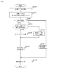
図1は、実施例1に係るストレージシステム1の構成を示す。ストレージシステム1は、ストレージコントローラ(DKC)10と、ストレージコントローラ10に接続された複数の記憶デバイス(200、200’)を有する。
FIG. 1 shows a configuration of a storage system 1 according to the first embodiment. The storage system 1 includes a storage controller (DKC) 10 and a plurality of storage devices (200, 200 ') connected to the storage controller 10.
記憶デバイス200、200’は、ホスト2などの上位装置からのライトデータを格納するための最終記憶媒体である。本実施例のストレージシステム1は、最終記憶装置として、磁気ディスクを記録媒体とするHDD(Hard Disk Drive)200’の他、フラッシュメモリなどの不揮発性半導体メモリを記憶媒体として用いるFMPK(Flash Memory PacKage)200を用いることができる。ただしその他の記憶デバイスを用いることも可能である。また、記憶デバイス200、200’は一例として、SAS(Serial Attached SCSI)規格に従って、ストレージコントローラ10(以下、「DKC10」と略記する)との通信を行う。
The storage devices 200 and 200 'are final storage media for storing write data from a host device such as the host 2. The storage system 1 according to the present embodiment uses an FMPK (Flash Memory PacKage) that uses a nonvolatile semiconductor memory such as a flash memory as a storage medium in addition to an HDD (Hard Disk Drive) 200 ′ that uses a magnetic disk as a recording medium as a final storage device. ) 200 can be used. However, other storage devices can be used. Further, as an example, the storage devices 200 and 200 ′ communicate with the storage controller 10 (hereinafter abbreviated as “DKC 10”) according to the SAS (Serial Attached SCSI) standard.
DKC10は複数のFMPKを、1又は複数のRAID(Redundant Arrays of Inexpensive/Independent Disks)グループ145として管理する。
The DKC 10 manages a plurality of FMPKs as one or a plurality of RAID (Redundant Arrays of Independent / Independent Disks) groups 145.
DKC10には、1以上のホスト2と、管理端末4が接続される。DKC100とホスト2とは、一例としてファイバチャネルを用いて形成されるSAN(Storage Area Network)1を介して接続される。DKC10と管理端末4とは、一例としてイーサネットを用いて形成されるネットワーク150を介して接続される。
One or more hosts 2 and a management terminal 4 are connected to the DKC 10. The DKC 100 and the host 2 are connected via a SAN (Storage Area Network) 1 formed using a fiber channel as an example. The DKC 10 and the management terminal 4 are connected via a network 150 formed using Ethernet as an example.
DKC10は少なくとも、プロセッサ11、ホストインタフェース(図中では「ホストIF」と表記)12、ディスクインタフェース(図中では「ディスクIF」と表記)13、メモリ14、パリティ演算回路15を有する。そしてプロセッサ11、ホストIF12、ディスクIF13、メモリ14、パリティ演算回路15は、相互結合スイッチ(相互結合SW)16を介して相互接続されている。これらの構成要素は、高性能化及び高可用性の確保のため、DKC10内に複数搭載されている。ただしこれらの構成要素が1つだけDKC10内に設けられている構成でもよい。
The DKC 10 includes at least a processor 11, a host interface (denoted as “host IF” in the figure) 12, a disk interface (denoted as “disk IF” in the figure) 13, a memory 14, and a parity operation circuit 15. The processor 11, the host IF 12, the disk IF 13, the memory 14, and the parity calculation circuit 15 are interconnected via a mutual coupling switch (mutual coupling SW) 16. A plurality of these components are mounted in the DKC 10 in order to ensure high performance and high availability. However, a configuration in which only one of these components is provided in the DKC 10 may be used.
ディスクIF13は少なくとも、バッファ131、記憶デバイス200、200’と通信するためのインタフェースコントローラ132(図中では「SAS-CTL」と表記されている)、及び転送回路(非図示)を有する。インタフェースコントローラ132は、記憶デバイス200、200’の用いているプロトコル(一例ではSAS)を、DKC10内部で用いられている通信プロトコル(一例としてPCI-Express)に変換するためのものである。本実施例では、記憶デバイス200、200’がSAS規格に従った通信を行うため、インタフェースコントローラ132にはSASコントローラ(以下、「SAS-CTL」と略記する)が用いられる。図1では、1つのディスクIF13にSAS-CTL132が1つのみ記載されているが、1つのディスクIF13に複数のSAS-CTL132が存在する構成を採用してもよい。
The disk IF 13 has at least an interface controller 132 (indicated as “SAS-CTL” in the drawing) for communicating with the buffer 131, the storage devices 200 and 200 ', and a transfer circuit (not shown). The interface controller 132 is for converting a protocol (SAS in one example) used by the storage devices 200 and 200 'into a communication protocol (PCI-Express as an example) used in the DKC 10. In this embodiment, since the storage devices 200 and 200 ′ perform communication in accordance with the SAS standard, a SAS controller (hereinafter abbreviated as “SAS-CTL”) is used as the interface controller 132. In FIG. 1, only one SAS-CTL 132 is described in one disk IF 13, but a configuration in which a plurality of SAS-CTLs 132 exist in one disk IF 13 may be adopted.
ディスクIF13は、たとえばFMPK200からデータを読み出し、読み出したデータをバッファ131に一時的に格納する。バッファ143に格納されたデータは、転送回路によって、メモリ14あるいは他のディスクIF13のバッファへと送信される。バッファ131はたとえば揮発性の半導体メモリから構成されるが、不揮発メモリを用いて構成されていても良い。
The disk IF 13 reads data from the FMPK 200, for example, and temporarily stores the read data in the buffer 131. The data stored in the buffer 143 is transmitted to the memory 14 or another buffer of the disk IF 13 by the transfer circuit. The buffer 131 is composed of a volatile semiconductor memory, for example, but may be composed of a nonvolatile memory.
ホストIF12は、ディスクIF13と同様に、インタフェースコントローラとバッファ、転送回路(非図示)を少なくとも有する。インタフェースコントローラは、ホスト2とDKC10間で用いられている通信プロトコル(たとえばファイバチャネル)と、DKC10内部で用いられている通信プロトコルを変換するためのものである。バッファはホスト2からのデータを一時的に格納するためのものである(逆にメモリ14からホスト2に転送するべきデータを一時的に格納するために用いられることもある)。
The host IF 12, like the disk IF 13, has at least an interface controller, a buffer, and a transfer circuit (not shown). The interface controller is for converting a communication protocol (for example, fiber channel) used between the host 2 and the DKC 10 and a communication protocol used inside the DKC 10. The buffer is for temporarily storing data from the host 2 (inversely, it may be used for temporarily storing data to be transferred from the memory 14 to the host 2).
パリティ演算回路15は、RAID技術で必要とされる冗長データの生成を行うハードウェアである。パリティ演算回路15により生成される冗長データの例としては、排他的論理和(XOR)、リードソロモン符号等がある。
The parity operation circuit 15 is hardware that generates redundant data required for RAID technology. Examples of redundant data generated by the parity operation circuit 15 include exclusive OR (XOR) and Reed-Solomon code.
プロセッサ11は、ホストIF12から到来するI/O要求の処理を行う。メモリ14は、プロセッサ11が実行するプログラムや、プロセッサが使用するストレージシステム1の各種管理情報を記憶するために用いられる。またメモリ14は、記憶デバイス200、200’に対するI/O対象データを一時的に記憶するためにも用いられる。以下、記憶デバイス200、200’に対するI/O対象データを一時的に記憶するために用いられる、メモリ14中の記憶領域を、「キャッシュ」と呼ぶ。メモリ14はDRAM、SRAM等の揮発性記憶媒体で構成されるが、別の実施形態として、不揮発性メモリを用いてメモリ14を構成してもよい。
The processor 11 processes an I / O request coming from the host IF 12. The memory 14 is used to store programs executed by the processor 11 and various management information of the storage system 1 used by the processor. The memory 14 is also used for temporarily storing I / O target data for the storage devices 200 and 200 '. Hereinafter, a storage area in the memory 14 that is used to temporarily store I / O target data for the storage devices 200 and 200 ′ is referred to as “cache”. The memory 14 is configured by a volatile storage medium such as DRAM or SRAM. However, as another embodiment, the memory 14 may be configured by using a nonvolatile memory.
ストレージシステム1は、先にも述べたとおり、FMPK200、HDD200’等の、複数種類の記憶デバイスを搭載できる。ただし以下では特に断りのない限り、ストレージシステム1にFMPK200のみが搭載されている構成を前提として説明する。
As described above, the storage system 1 can be equipped with a plurality of types of storage devices such as the FMPK 200 and the HDD 200 '. However, the following description is based on the assumption that only the FMPK 200 is mounted in the storage system 1 unless otherwise specified.
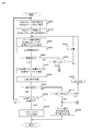
図2を用いて、FMPK200の構成について説明する。FMPK200は、デバイスコントローラ(FMコントローラ)201と複数のFMチップ210から構成される。FMコントローラ201は、メモリ202、プロセッサ203、データの圧縮伸長を行うための圧縮伸長回路204、パリティを計算するためのパリティ演算回路205、SAS-CTL206、FM-IF207を備える。メモリ202、プロセッサ203、圧縮伸長回路204、パリティ演算回路205、SAS-CTL206、FM-IF207は、内部接続スイッチ(内部接続SW)208を介して相互接続されている。
The configuration of the FMPK 200 will be described with reference to FIG. The FMPK 200 includes a device controller (FM controller) 201 and a plurality of FM chips 210. The FM controller 201 includes a memory 202, a processor 203, a compression / decompression circuit 204 for compressing / decompressing data, a parity operation circuit 205 for calculating parity, a SAS-CTL 206, and an FM-IF 207. The memory 202, the processor 203, the compression / decompression circuit 204, the parity operation circuit 205, the SAS-CTL 206, and the FM-IF 207 are interconnected via an internal connection switch (internal connection SW) 208.
SAS-CTL206は、FMPK200とDKC10間の通信を行うためのインタフェースコントローラである。SAS-CTL206は、伝送線(SASリンク)を介して、DKC10のSAS-CTL132に接続される。またFM-IF207は、FMコントローラ201とFMチップ210間の通信を行うためのインタフェースコントローラである。
SAS-CTL 206 is an interface controller for performing communication between the FMPK 200 and the DKC 10. The SAS-CTL 206 is connected to the SAS-CTL 132 of the DKC 10 via a transmission line (SAS link). The FM-IF 207 is an interface controller for performing communication between the FM controller 201 and the FM chip 210.
プロセッサ203は、DKC10から到来する各種コマンドに係る処理を行う。メモリ202には、プロセッサ203が実行するプログラムや、各種管理情報が記憶される。メモリ202には、DRAM等の揮発性メモリが用いられる。ただしメモリ202に不揮発性メモリを使用しても良い。
The processor 203 performs processing related to various commands coming from the DKC 10. The memory 202 stores programs executed by the processor 203 and various management information. For the memory 202, a volatile memory such as a DRAM is used. However, a nonvolatile memory may be used for the memory 202.
圧縮伸長回路204は、データの圧縮、または圧縮されたデータの伸長を行う機能を備えたハードウェアである。またパリティ演算回路205は、DKC10が備えるパリティ演算回路15と同様の機能を持つハードウェア、つまりRAID技術で必要とされる冗長データの生成機能を有する。
The compression / decompression circuit 204 is hardware having a function of compressing data or decompressing the compressed data. The parity operation circuit 205 has hardware having a function similar to that of the parity operation circuit 15 included in the DKC 10, that is, a redundant data generation function required in the RAID technology.
FMチップ210は、不揮発性半導体メモリチップで、一例としてNAND型フラッシュメモリである。フラッシュメモリは周知のとおり、ページ単位でデータの読み出し・書き込みが行われ、またデータ消去は、複数ページの集合であるブロック単位で行われる。そして一度書き込みが行われたページは上書きが出来ず、一度書き込みが行われたページに対して再度書き込みを行うためには、当該ページを含むブロック全体を消去する必要がある。そのため、FMPK200は、FMPK200が接続されるDKC10に対しては、FMチップ210の有する記憶領域をそのまま提供することはせず、論理的な記憶空間を提供する。
The FM chip 210 is a nonvolatile semiconductor memory chip, and is a NAND flash memory as an example. As is well known, data is read / written in units of pages in the flash memory, and data erasure is performed in units of blocks that are a set of a plurality of pages. A page once written cannot be overwritten, and in order to rewrite a page once written, it is necessary to erase the entire block including the page. Therefore, the FMPK 200 does not directly provide the storage area of the FM chip 210 to the DKC 10 to which the FMPK 200 is connected, but provides a logical storage space.
なお、FMPK200は、圧縮伸長回路204により、DKC10からのライトデータを圧縮してFMチップ210に格納することができる。ただし、DKC10に対しては原則として、透過的にデータ圧縮を行う。FMPK200はDKC10に対し、所定のサイズの記憶空間(論理アドレス空間)を提供する。DKC10がFMPK200にデータを書き込む際には、この論理アドレス空間上のアドレスとライト対象データのサイズを指定したライトコマンドを発行する。一例として、DKC10がFMPK200に対し、論理アドレス空間の先頭(アドレス0)に48KBのデータを書き込むライトコマンド(及び48KBのライトデータ)を送信したとする。またFMPK200がこの48KBのデータを圧縮した結果、8KBの圧縮データになり、この8KBの圧縮データがFMチップ210に格納されたとする。この状態において、DKC10がこのデータを読み出す場合には、論理アドレス空間の先頭(アドレス0)とリードデータサイズ(たとえば48KB)を指定したリードコマンドを発行することで、先ほど格納した48KBのデータを読み出すことができる。読み出しの過程で、FMPK200は圧縮伸長回路204により、8KBの圧縮データを48KBに伸長(復元)し、伸長されたデータをDKC10に返送するよう動作するからである。そのためDKC10は、(実際にはデータが圧縮されて格納されている場合でも)論理アドレス空間上にデータが非圧縮状態で格納されているかのように認識する。
The FMPK 200 can compress the write data from the DKC 10 and store it in the FM chip 210 by the compression / decompression circuit 204. However, for DKC 10, in principle, data compression is performed transparently. The FMPK 200 provides a storage space (logical address space) of a predetermined size to the DKC 10. When the DKC 10 writes data to the FMPK 200, it issues a write command specifying the address in the logical address space and the size of the write target data. As an example, it is assumed that the DKC 10 transmits to the FMPK 200 a write command (and 48 KB write data) for writing 48 KB data at the head (address 0) of the logical address space. Further, it is assumed that the FMPK 200 compresses the 48 KB data to result in 8 KB compressed data, and the 8 KB compressed data is stored in the FM chip 210. In this state, when the DKC 10 reads this data, the 48 KB data stored earlier is read by issuing a read command designating the head of the logical address space (address 0) and the read data size (eg, 48 KB). be able to. This is because, in the reading process, the FMPK 200 operates to expand (restore) 8 KB of compressed data to 48 KB by the compression / decompression circuit 204 and return the expanded data to the DKC 10. Therefore, the DKC 10 recognizes as if the data is stored in the uncompressed state in the logical address space (even if the data is actually compressed and stored).
上では、データの圧縮、伸長が、圧縮伸長回路204というハードウェアで行われる例について説明したが、必ずしもデータの圧縮、伸長を、ハードウェアを用いて行わなければならないわけではない。プロセッサ203が圧縮、伸長を行うプログラムを実行することによって、データの圧縮、伸長を行うようにしてもよい。またパリティ演算回路205についても同様で、パリティ演算回路205というハードウェアでパリティの演算を行わなければならないわけではない。プロセッサ203がパリティ演算を行うプログラムを実行することによって、パリティ演算を行うようにしてもよい。
In the above, an example in which data compression / decompression is performed by hardware such as the compression / decompression circuit 204 has been described. However, data compression / decompression is not necessarily performed using hardware. Data may be compressed and decompressed by the processor 203 executing a program that performs compression and decompression. The same applies to the parity operation circuit 205, and the parity operation circuit 205 does not have to perform the parity operation with hardware. The processor 203 may execute the parity calculation by executing a program that performs the parity calculation.
さらに、上ではFMPK200が圧縮/伸長機能、パリティ演算機能を備えている例を説明したが、圧縮/伸長機能、またはパリティ演算機能を有していないFMPK200がストレージシステム1内に存在してもよい。FMPK200が圧縮/伸長機能を有していない場合には、データは圧縮して格納されない。またFMPK200がパリティ演算機能を有していない場合には、DKC10がパリティの生成を行う。
Further, the example in which the FMPK 200 has the compression / decompression function and the parity calculation function has been described above. However, the FMPK 200 that does not have the compression / decompression function or the parity calculation function may exist in the storage system 1. . If the FMPK 200 does not have a compression / decompression function, the data is not compressed and stored. When the FMPK 200 does not have a parity calculation function, the DKC 10 generates a parity.
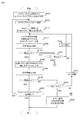
続いて、ストレージシステム1で用いられる記憶領域の概念について説明する。ストレージシステム1は、複数のFMPK200を1つのRAID(Redundant Arrays of Inexpensive/Independent Disks)グループとして管理する。そしてRAIDグループ内で1つ(あるいは2つ)のFMPK200に障害が発生してデータアクセスできなくなった場合に、残りのFMPK200内のデータを用いて、障害が発生したFMPK200に格納されていたデータを復旧できるようにしている。また、RAIDグループ内の一部の記憶領域(あるいは全記憶領域)を、ホスト2などの上位装置に提供する。
Next, the concept of storage areas used in the storage system 1 will be described. The storage system 1 manages a plurality of FMPKs 200 as a single RAID (Redundant Arrays of Independent / Independent Disks) group. When one (or two) FMPK 200 in the RAID group fails and data access becomes impossible, the data stored in the failed FMPK 200 is used by using the remaining data in the FMPK 200. I am trying to recover. Further, a part of the storage area (or all storage areas) in the RAID group is provided to a host device such as the host 2.
RAIDグループ内の記憶領域について、図3を用いて説明する。図3において、FMPK#x(xは0~3の数値)は、FMPK200がDKC10に提供している記憶空間を表している。DKC10は、複数(図3の例では4つ)のFMPK200から1つのRAIDグループ20を構成し、RAIDグループ20に所属する各FMPK(FMPK#0(200-0)~FMPK#3(200-3))上の記憶空間を、ストライプブロックと呼ぶ複数の固定サイズの記憶領域に分割して管理している。
The storage area in the RAID group will be described with reference to FIG. In FIG. 3, FMPK # x (x is a numerical value from 0 to 3) represents a storage space provided by the FMPK 200 to the DKC 10. The DKC 10 constitutes one RAID group 20 from a plurality (four in the example of FIG. 3) of FMPKs 200, and FMPKs (FMPK # 0 (200-0) to FMPK # 3 (200-3) belonging to the RAID group 20 are included. )) The above storage space is managed by dividing it into a plurality of fixed-size storage areas called stripe blocks.
また図3では、RAIDグループ20のRAIDレベル(RAID技術におけるデータ冗長化方式を表すもので、一般的にはRAID1~RAID6の種類がある)がRAID5である場合の例を表している。DKC10は、図3においてRAIDグループ20内の、「0」、「1」、「P」などのボックスがストライプブロックを表しており、1つのRAIDグループ20内の各ストライプブロックのサイズ(以下では「ストライプサイズ」と呼ばれる)は同じである。ストライプサイズとしては、たとえば64KB、256KB、512KBなどが用いられる。また、各ストライプブロックに付されている、「1」等の番号のことを、「ストライプブロック番号」と呼ぶ。
FIG. 3 shows an example in which the RAID level of the RAID group 20 (representing a data redundancy method in the RAID technology and generally having RAID1 to RAID6 types) is RAID5. In the DKC 10, boxes such as “0”, “1”, “P” in the RAID group 20 in FIG. 3 represent stripe blocks, and the size of each stripe block in one RAID group 20 (hereinafter “ Called “stripe size” is the same. As the stripe size, for example, 64 KB, 256 KB, 512 KB or the like is used. A number such as “1” assigned to each stripe block is referred to as a “stripe block number”.
図3で、ストライプブロックのうち、「P」と記載されているストライプブロックは、冗長データの格納されるストライプブロックであり、これを「パリティストライプ」と呼ぶ。一方、数字(0、1等)が記載されているストライプブロックは、ホスト2等の上位装置から書き込まれるデータ(冗長データではないデータ)が格納されるストライプブロックである。このストライプブロックのことは、「データストライプ」と呼ばれる。
In FIG. 3, the stripe block described as “P” in the stripe block is a stripe block in which redundant data is stored, and this is called a “parity stripe”. On the other hand, a stripe block in which numbers (0, 1 etc.) are written is a stripe block in which data (data which is not redundant data) written from a host device such as the host 2 is stored. This stripe block is called “data stripe”.
図3に示されたRAIDグループ20では、たとえばFMPK#3(200-3)の先頭に位置するストライプブロックはパリティストライプ301-3である。そしてDKC10がこのパリティストライプ301-3に格納される冗長データを作成する際、各FMPK200(FMPK#0(200-0)~FMPK#2(200-2))の先頭に位置するデータストライプ(ストライプブロック301-0、301-1、301-2)に格納されるデータに対して所定の演算(たとえば排他的論理和(XOR)等)を施すことによって、冗長データを生成する。
In the RAID group 20 shown in FIG. 3, for example, the stripe block located at the head of FMPK # 3 (200-3) is the parity stripe 301-3. When the DKC 10 creates redundant data stored in the parity stripe 301-3, the data stripe (stripe) positioned at the head of each FMPK 200 (FMPK # 0 (200-0) to FMPK # 2 (200-2)) is stored. Redundant data is generated by performing a predetermined operation (for example, exclusive OR (XOR) or the like) on the data stored in the blocks 301-0, 301-1 and 301-2).
以下、パリティストライプと、当該パリティストライプに格納される冗長データを生成するために用いられるデータストライプのセット(たとえば図3中の要素300)のことを、「ストライプライン」と呼ぶ。実施例1に係るストレージシステム1の場合、図3に示されているストライプライン300のように、1つのストライプラインに属する各ストライプブロックは、FMPK200-0~200-3の記憶空間の同じ位置(アドレス)に存在するという規則に基づいて、ストライプラインが構成される。
Hereinafter, a parity stripe and a set of data stripes (for example, element 300 in FIG. 3) used to generate redundant data stored in the parity stripe are referred to as “strip lines”. In the case of the storage system 1 according to the first embodiment, like the stripe line 300 shown in FIG. 3, each stripe block belonging to one stripe line has the same position in the storage space of the FMPKs 200-0 to 200-3 ( The stripe line is formed based on the rule that the address exists.
なお、先に説明したストライプブロック番号は、データストライプに付される番号で、RAIDグループ内で一意な番号である。図3に示されているように、DKC10は、RAIDグループを構成する各FMPK200の先頭に位置するデータストライプに0、1、2の番号を付し、以下順に、3、4、5...の連続番号を付して、データストライプを管理している。以下、ストライプブロック番号がn番(nは0以上の整数値)であるデータストライプのことを、「データストライプn」と表記する。
The stripe block number described above is a number assigned to the data stripe, and is a unique number within the RAID group. As shown in FIG. 3, the DKC 10 assigns numbers 0, 1 and 2 to the data stripes located at the head of each FMPK 200 constituting the RAID group. . . The data stripe is managed by assigning a serial number. Hereinafter, a data stripe whose stripe block number is n (n is an integer value of 0 or more) is referred to as “data stripe n”.
またストレージシステム1では、RAIDグループに属する各記憶デバイス200(200’)に対し、RAIDグループ内で一意な番号を付して管理する。この一意な番号は「RAIDグループ内位置番号」または「位置番号」と呼ばれる。具体的には、RAIDグループ内の先頭ストライプラインに、データストライプ0~データストライプk(k>0)が含まれている場合、データストライプm(0≦m≦k)が格納される記憶デバイス200(200’)の位置番号が「m」と定められる。
The storage system 1 manages each storage device 200 (200 ') belonging to the RAID group by assigning a unique number within the RAID group. This unique number is called a “position number in the RAID group” or “position number”. Specifically, when the first stripe line in the RAID group includes data stripe 0 to data stripe k (k> 0), the storage device 200 in which the data stripe m (0 ≦ m ≦ k) is stored. The position number of (200 ′) is defined as “m”.
そしてRAID5のように1ストライプライン内に1つのパリティストライプが存在するRAID構成の場合、パリティストライプが格納される記憶デバイス200(200’)の位置番号が「k+1」と定められる。さらにRAID6のように、1ストライプライン内に2つのパリティストライプが存在するRAID構成の場合、パリティストライプが格納される2つの記憶デバイス200(200’)の位置番号はそれぞれ、「k+1」及び「k+2」と定められる。
In the case of a RAID configuration in which one parity stripe exists within one stripe line as in RAID 5, the position number of the storage device 200 (200 ') in which the parity stripe is stored is determined as "k + 1". Further, in the case of a RAID configuration in which two parity stripes exist within one stripe line as in RAID 6, the position numbers of the two storage devices 200 (200 ′) in which the parity stripes are stored are “k + 1” and “k + 2”, respectively. "
図3に示されているRAIDグループの場合、先頭ストライプライン300内のデータストライプ0~2が格納される3つの記憶デバイス200(200’)の位置番号は0、1、2と定められる。そしてデータストライプ0~2と同一ストライプライン内の冗長データ(パリティ)の格納される記憶デバイス200(200’)の位置番号は3と定められる。
In the case of the RAID group shown in FIG. 3, the position numbers of the three storage devices 200 (200 ') in which the data stripes 0 to 2 in the leading stripe line 300 are stored are defined as 0, 1, and 2. The position number of the storage device 200 (200 ') in which redundant data (parity) in the same stripe line as the data stripes 0 to 2 is stored is determined to be 3.
また、DKC10は、ホスト2等の上位装置に対し、論理ユニット(LU)と呼ばれる記憶空間を、1以上提供する。RAIDグループにより形成される記憶空間(以下、「RAIDグループの記憶空間」と呼ぶ)と、論理ユニットの関係について、図4を用いて説明する。RAIDグループの記憶空間とは、図3に示されているRAIDグループ内の領域のうち、データストライプ0から順に、データストライプのみを並べることによって形成される記憶空間である。DKC10は、1つのRAIDグループの記憶空間上の連続領域を論理ユニットと定義することができる。1つのRAIDグループの記憶空間上に複数の論理ユニットを定義してもよいし、1つのRAIDグループの記憶空間全体を1つの論理ユニットとして定義することもできる。図4では、RAIDグループの記憶空間上に2つの論理ユニット(LU#0、LU#1)が定義されている例を表している。
Also, the DKC 10 provides one or more storage spaces called logical units (LU) to the host device such as the host 2. A relationship between a storage space formed by a RAID group (hereinafter referred to as “RAID group storage space”) and a logical unit will be described with reference to FIG. The storage space of the RAID group is a storage space formed by arranging only data stripes in order from the data stripe 0 in the area in the RAID group shown in FIG. The DKC 10 can define a continuous area on the storage space of one RAID group as a logical unit. A plurality of logical units may be defined on the storage space of one RAID group, or the entire storage space of one RAID group may be defined as one logical unit. FIG. 4 shows an example in which two logical units (LU # 0, LU # 1) are defined in the storage space of the RAID group.
一例として、ストレージシステム1が、ホスト2からLU#0の先頭から3ストライプブロック分の領域に対するデータ書き込み要求(ライトコマンド)を受け付けた場合に行われる処理の概要を説明する。なお、LU#0は図3に示されているRAIDグループに定義されているものとする。この場合、DKC10はライトコマンドとともに受信した3ストライプブロック分のデータを、1ストライプブロックごとに分割する。以下、分割されて生成された3つのデータをそれぞれ、「データ0」、「データ1」、「データ2」と呼ぶ。DKC10はデータ0~データ2を用いて冗長データ(パリティ)を生成し、データ0~データ2及び生成されたパリティをそれぞれ、異なる記憶デバイス200に格納する。LU#が図3に示されているRAIDグループ内に定義されている場合、データ0~データ2及びパリティはそれぞれ、FMPK(200-0)~FMPK(200-3)に格納される。
As an example, an outline of processing performed when the storage system 1 receives a data write request (write command) for an area corresponding to three stripe blocks from the head of LU # 0 from the host 2 will be described. It is assumed that LU # 0 is defined in the RAID group shown in FIG. In this case, the DKC 10 divides the data for three stripe blocks received together with the write command for each stripe block. Hereinafter, the three pieces of data generated by the division are referred to as “data 0”, “data 1”, and “data 2”, respectively. The DKC 10 generates redundant data (parity) using the data 0 to data 2 and stores the data 0 to data 2 and the generated parity in different storage devices 200, respectively. When LU # is defined in the RAID group shown in FIG. 3, data 0 to data 2 and parity are stored in FMPK (200-0) to FMPK (200-3), respectively.
LU#0が定義されているRAIDグループのRAIDレベルが、図3のようにRAID5である場合、パリティはデータ0~データ2の排他的論理和(XOR)を計算することで生成できる。パリティの計算は、DKC10のパリティ演算回路15を用いて行われる。ただしRAIDグループを構成する記憶デバイス200が図2のように、パリティ演算回路205等のパリティ生成機能を備えている場合には、記憶デバイス200の有するパリティ生成機能を用いてパリティを生成することもできる。
When the RAID level of the RAID group in which LU # 0 is defined is RAID 5 as shown in FIG. 3, the parity can be generated by calculating the exclusive OR (XOR) of data 0 to data 2. Parity calculation is performed using the parity calculation circuit 15 of the DKC 10. However, when the storage device 200 constituting the RAID group has a parity generation function such as the parity calculation circuit 205 as shown in FIG. 2, the parity may be generated using the parity generation function of the storage device 200. it can.
RAIDグループ、論理ユニット(LU)を管理するために、DKC10はメモリ14に、デバイス管理テーブル、RAIDグループ管理テーブル(RG管理テーブル)、LU管理テーブルという3種類の管理情報を有する。図5は、デバイス管理テーブルT1000の例を示している。
In order to manage RAID groups and logical units (LUs), the DKC 10 has three types of management information in the memory 14: a device management table, a RAID group management table (RG management table), and an LU management table. FIG. 5 shows an example of the device management table T1000.
デバイス管理テーブルT1000は、ストレージシステム1に搭載された各記憶デバイス200(または200’)についての情報を管理するためのテーブルである。デバイス管理テーブルT1000内の各行(以下では、テーブル内の行のことを「レコード」と呼ぶ)に、ストレージシステム1に搭載された各記憶デバイス200(200’)の情報が格納される。デバイス管理テーブルT1000のレコードは、デバイス#(T1001)、デバイス種別(T1002)、所属RG#(T1003)、デバイスステータス(T1004)、圧縮機能サポート(T1005)、パリティ演算機能サポート(T1006)、サイズ(T1007)の項目を有する。
The device management table T1000 is a table for managing information about each storage device 200 (or 200 ') mounted in the storage system 1. Information of each storage device 200 (200 ') mounted in the storage system 1 is stored in each row in the device management table T1000 (hereinafter, the row in the table is referred to as "record"). The record of the device management table T1000 includes device # (T1001), device type (T1002), affiliation RG # (T1003), device status (T1004), compression function support (T1005), parity operation function support (T1006), size ( T1007).
DKC10は、ストレージシステム1に搭載された各記憶デバイス200(または200’)に、一意な識別番号を付して管理しており、この識別番号は「デバイス番号」(または「デバイス#」)と呼ばれる。デバイス#(T1001)には、記憶デバイス200(200’)のデバイス#が格納される。デバイス種別(T1002)は、記憶デバイス200(200’)の種類についての情報を格納するための項目である。本実施例の場合、デバイス種別(T1002)には、「FMPK」または「HDD」のいずれかの情報が格納される。あるレコードのデバイス種別(T1002)に「FMPK」が格納されている場合、当該レコードで管理される記憶デバイスがFMPK200であることを表しており、また「HDD」が格納されている場合、当該レコードで管理される記憶デバイスがHDD200’であることを表している。所属RG#(T1003)については後述する。
The DKC 10 manages each storage device 200 (or 200 ′) mounted in the storage system 1 with a unique identification number, and this identification number is “device number” (or “device #”). be called. Device # (T1001) stores device # of storage device 200 (200 '). The device type (T1002) is an item for storing information about the type of the storage device 200 (200 '). In this embodiment, the device type (T1002) stores either “FMPK” or “HDD” information. When “FMPK” is stored in the device type (T1002) of a record, this indicates that the storage device managed by the record is FMPK200, and when “HDD” is stored, the record This indicates that the storage device managed by is HDD 200 ′. The affiliation RG # (T1003) will be described later.
デバイスステータス(T1004)には、記憶デバイスの状態が格納される。デバイスステータス(T1004)に「正常」が格納されている場合、当該レコードで管理される記憶デバイスは正常に稼働していることを表している。デバイスステータス(T1004)に「閉塞」が格納されている場合、当該レコードで管理される記憶デバイスは、障害が発生した等の理由により、稼働していない(閉塞状態にある)ことを表している。
The device status (T1004) stores the state of the storage device. When “normal” is stored in the device status (T1004), this indicates that the storage device managed by the record is operating normally. When “blocked” is stored in the device status (T1004), this indicates that the storage device managed in the record is not operating (is blocked) due to a failure or the like. .
デバイスステータス(T1004)に「障害復旧中(復旧元)」または「障害復旧中(復旧先)」が格納されている場合、当該レコードで管理される記憶デバイスの所属するRAIDグループについてデータ復旧処理が行われていることを表している。詳細は後述するが、たとえば1台の記憶デバイスに障害が発生した場合、データ復旧処理では障害が発生した記憶デバイスの代わりとなるデバイス(以下、これを「スペアデバイス」と呼ぶ)を1台用意する。そしてDKC10は、障害が発生した記憶デバイスのデバイスステータス(T1004)には「障害復旧中(復旧元)」を格納する。またDKC10は、スペアデバイスとされる記憶デバイスのデバイスステータス(T1004)に「障害復旧中(復旧先)」を格納する。そして障害が発生した記憶デバイスに格納されていたデータを復旧し、スペアデバイスに書き込むことで、データ復旧を行う。
If “failure recovery in progress (recovery source)” or “failure recovery in progress (recovery destination)” is stored in the device status (T1004), data recovery processing is performed for the RAID group to which the storage device managed by the record belongs. Indicates what is being done. Although details will be described later, for example, when a failure occurs in one storage device, a device that replaces the failed storage device in the data recovery process (hereinafter referred to as “spare device”) is prepared. To do. The DKC 10 stores “failure recovery in progress (recovery source)” in the device status (T1004) of the storage device in which the failure has occurred. In addition, the DKC 10 stores “failure recovery in progress (recovery destination)” in the device status (T1004) of the storage device to be a spare device. Then, the data stored in the storage device in which the failure has occurred is recovered, and the data is restored by writing to the spare device.
圧縮機能サポート(T1005)、パリティ演算機能サポート(T1006)にはそれぞれ、当該レコードで管理される記憶デバイスの、圧縮機能のサポート有無、パリティ演算機能のサポート有無についての情報が格納される。圧縮機能サポート(T1005)に「サポート」が格納されている場合には、当該レコードで管理される記憶デバイスが圧縮機能を有していることを意味し、「未サポート」が格納されている場合には、当該レコードで管理される記憶デバイスが圧縮機能を有していないことを意味する。パリティ演算機能サポート(T1006)にも同様に、「サポート」または「未サポート」のいずれかの情報が格納され、「サポート」が格納されている場合には、当該レコードで管理される記憶デバイスがパリティ演算機能を有していることを意味する。
In the compression function support (T1005) and the parity calculation function support (T1006), information on whether or not the compression function is supported and whether the parity calculation function is supported is stored in the storage device managed by the record. When “support” is stored in the compression function support (T1005), this means that the storage device managed by the record has the compression function, and “unsupported” is stored. Means that the storage device managed by the record does not have a compression function. Similarly, the parity calculation function support (T1006) stores either “support” or “unsupported” information. If “support” is stored, the storage device managed by the record is It means that it has a parity operation function.
圧縮機能サポート(T1005)、パリティ演算機能サポート(T1006)に格納される情報は、ストレージシステム1の管理者が、管理端末を用いて設定してもよい。あるいは別の実施形態として、DKC10が各記憶デバイスに対して、各記憶デバイスが有する機能を問い合わせるコマンドを発行することによって、各記憶デバイスが圧縮機能及び/またはパリティ演算機能を有しているか問い合わせ、DKC10がこの問い合わせ結果を圧縮機能サポート(T1005)、パリティ演算機能サポート(T1006)に反映するようにしてもよい。
Information stored in the compression function support (T1005) and the parity calculation function support (T1006) may be set by the administrator of the storage system 1 using the management terminal. Alternatively, as another embodiment, the DKC 10 inquires whether each storage device has a compression function and / or a parity calculation function by issuing a command for inquiring the function of each storage device to each storage device. The DKC 10 may reflect the inquiry result to the compression function support (T1005) and the parity calculation function support (T1006).
サイズ(T1007)には、記憶デバイスの容量、具体的には記憶デバイス200(200’)がDKC10に対して提供している記憶空間のサイズが格納される。この記憶空間のサイズについての情報は、DKC10が記憶デバイス200(200’)に対して、サイズの問い合わせを行うコマンドを発行することで、記憶デバイス200(200’)から取得可能な情報である。なお、記憶デバイス200がFMPK200のように圧縮機能を有する場合、記憶空間のサイズは、記憶デバイス200自身が有する記憶媒体(たとえばFMチップ210)の合計サイズよりも大きいこともある。
The size (T1007) stores the capacity of the storage device, specifically the size of the storage space provided to the DKC 10 by the storage device 200 (200 '). The information about the size of the storage space is information that can be acquired from the storage device 200 (200 ') when the DKC 10 issues a command for inquiring the size to the storage device 200 (200'). When the storage device 200 has a compression function like the FMPK 200, the size of the storage space may be larger than the total size of the storage medium (for example, the FM chip 210) included in the storage device 200 itself.
図6は、RG管理テーブルT1100の例を示している。デバイス管理テーブルT1000と同様、RG管理テーブルT1100内の複数のレコードの各々に、RAIDグループについての情報が格納されている。
FIG. 6 shows an example of the RG management table T1100. Similar to the device management table T1000, information about a RAID group is stored in each of a plurality of records in the RG management table T1100.
DKC10は、ストレージシステム1内に定義された各RAIDグループに一意な識別番号を付して管理しており、この識別番号は「RAIDグループ番号」または「RG#」と呼ばれる。RG#(T1101)には、RAIDグループ番号(RG#)が格納される。
所属デバイス#(T1102)は、RAIDグループに含まれている記憶デバイス200(200’)のデバイス#が記憶される。たとえばDKC10が、デバイス#が0、1、2、3、4番の記憶デバイスを用いてRAIDグループを形成した時(仮にそのRG#が0番であったとする)、DKC10は、RG#(T1101)が0のレコードの、所属デバイス#(T1102)の欄に、「0、1、2、3、4」を格納する。また、図5のデバイス管理テーブルT1000内の各レコードの所属RG#(T1003)には、各記憶デバイスの所属しているRAIDグループ番号が格納される。 TheDKC 10 manages each RAID group defined in the storage system 1 with a unique identification number, and this identification number is called “RAID group number” or “RG #”. A RAID group number (RG #) is stored in RG # (T1101).
The belonging device # (T1102) stores the device # of the storage device 200 (200 ′) included in the RAID group. For example, when theDKC 10 forms a RAID group using the storage devices with device numbers 0, 1, 2, 3, and 4 (assuming that RG # is number 0), the DKC 10 stores RG # (T1101). "0", "0, 1, 2, 3, 4" are stored in the column of belonging device # (T1102) of the record with 0. Further, the RG # (T1003) of each record in the device management table T1000 in FIG. 5 stores the RAID group number to which each storage device belongs.
所属デバイス#(T1102)は、RAIDグループに含まれている記憶デバイス200(200’)のデバイス#が記憶される。たとえばDKC10が、デバイス#が0、1、2、3、4番の記憶デバイスを用いてRAIDグループを形成した時(仮にそのRG#が0番であったとする)、DKC10は、RG#(T1101)が0のレコードの、所属デバイス#(T1102)の欄に、「0、1、2、3、4」を格納する。また、図5のデバイス管理テーブルT1000内の各レコードの所属RG#(T1003)には、各記憶デバイスの所属しているRAIDグループ番号が格納される。 The
The belonging device # (T1102) stores the device # of the storage device 200 (200 ′) included in the RAID group. For example, when the
先にも述べたが、ストレージシステム1は、RAIDグループに属する各記憶デバイス200(200’)に、位置番号を対応付けて管理する。そのため、所属デバイス#(T1102)に登録された各FMPK200には、位置番号(T1102’)が対応付けられる。図6において、レコードT1100-1で管理されているRAIDグループ(RG#(T1101)が1)にはデバイス#が8~15番のFMPK200が所属しているが、各FMPK200には、位置番号0~7の番号が対応付けられている。
As described above, the storage system 1 manages each storage device 200 (200 ') belonging to the RAID group in association with a position number. Therefore, each FMPK 200 registered in the belonging device # (T1102) is associated with a position number (T1102 '). In FIG. 6, the FMPK 200 with device numbers 8 to 15 belongs to the RAID group (RG # (T1101) is 1) managed by the record T1100-1, but each FMPK 200 has a position number 0. Numbers 7 to 7 are associated.
RAID構成(T1103)は、RAIDグループの構成についての情報が格納される項目であり、少なくとも、RAID技術によるデータ保護方式を表すRAIDレベル、冗長データを生成する時に用いられるデータストライプの数、生成されるパリティストライプの数の情報が格納される。図6の例では、レコードT1100-1のRAID構成(T1103)は「RAID5(3D+1P)」だが、これはRAIDレベルが5であること、そして3つのデータストライプから1つのパリティを生成するRAID構成であることを表している。
The RAID configuration (T1103) is an item in which information about the configuration of the RAID group is stored. The RAID configuration (T1103) includes at least a RAID level that represents a data protection method using RAID technology and the number of data stripes used when generating redundant data. Information on the number of parity stripes to be stored is stored. In the example of FIG. 6, the RAID configuration (T1103) of the record T1100-1 is “RAID5 (3D + 1P)”. This is a RAID configuration in which the RAID level is 5, and one parity is generated from three data stripes. It represents something.
RG容量(T1104)、ストライプサイズ(T1105)にはそれぞれ、RAIDグループに格納できるデータの量(サイズ)、ストライプサイズが格納される。本実施例では、RG容量(T1104)に格納される容量は、RAIDグループ内全データストライプの合計サイズであり、パリティのサイズは含まれない。ただし別の実施形態として、パリティのサイズを含んだ容量が格納されるようにしてもよい。
The RG capacity (T1104) and stripe size (T1105) store the amount of data (size) and stripe size that can be stored in the RAID group, respectively. In this embodiment, the capacity stored in the RG capacity (T1104) is the total size of all data stripes in the RAID group, and does not include the size of parity. However, as another embodiment, a capacity including the size of the parity may be stored.
RGステータス(T1106)には、RAIDグループの状態(「正常」、「障害復旧中」、「障害復旧失敗」のいずれかの状態)が格納される。RAIDグループの状態の意味は、デバイスステータス(T1004)と同様であり、RGステータス(T1106)に「正常」が格納されている場合には、RAIDグループが正常に稼働していることを表している。また「障害復旧中」が格納されている場合には、RAIDグループの復旧処理が行われていることを表しており、「障害復旧失敗」が格納されている場合にはRAIDグループが閉塞状態にあることを表している。
In the RG status (T1106), the status of the RAID group (any state of “normal”, “failure recovery”, “failure recovery failure”) is stored. The meaning of the status of the RAID group is the same as that of the device status (T1004), and when “normal” is stored in the RG status (T1106), it indicates that the RAID group is operating normally. . If “failure recovery” is stored, it indicates that the RAID group recovery processing is being performed. If “failure recovery failure” is stored, the RAID group is blocked. It represents something.
圧縮(T1107)、パリティ演算(T1108)にはそれぞれ、「実施」または「未実施」の情報が格納される。圧縮(T1107)に「実施」が格納されている場合、当該レコードで管理されるRAIDグループでは、記憶デバイス(FMPK200)が備える圧縮機能を用いたデータ圧縮が行われ、圧縮データがFMPK200に格納されていることを表している(逆に「未実施」が格納されている場合には、FMPK200がデータ圧縮を行っていないことを意味する)。パリティ演算(T1108)に「実施」が格納されている場合、当該レコードで管理されるRAIDグループに格納されるパリティは、FMPK200が備えるパリティ演算機能を用いて算出されることを表している。
Compressed (T1107) and parity calculation (T1108) store “executed” or “unexecuted” information, respectively. When “execution” is stored in the compression (T1107), the RAID group managed by the record performs data compression using the compression function of the storage device (FMPK200), and the compressed data is stored in the FMPK200. (Conversely, when “not yet executed” is stored, it means that the FMPK 200 is not performing data compression). When “execution” is stored in the parity calculation (T1108), it indicates that the parity stored in the RAID group managed by the record is calculated using the parity calculation function provided in the FMPK 200.
DKC10は各RAIDグループについて、RAIDグループに所属する全記憶デバイスが圧縮機能をサポートしている場合(所属デバイス#(T1102)で特定される全記憶デバイスの、圧縮機能サポート(T1005)が「サポート」である場合)、圧縮(T1107)に「実施」を設定する。同様に、RAIDグループに所属する全記憶デバイスがパリティ演算機能をサポートしている場合(所属デバイス#(T1102)で特定される全記憶デバイスの、パリティ演算機能サポート(T1006)が「サポート」である場合)、パリティ演算(T1108)に「実施」を設定する。また別の実施形態として、ストレージシステム1の管理者が、管理端末を用いて圧縮(T1107)、パリティ演算(T1108)に「実施」または「未実施」を設定するようにしてもよい。
In the DKC 10, for all RAID groups, when all storage devices belonging to the RAID group support the compression function (the compression function support (T1005) of all storage devices specified by the belonging device # (T1102) is “supported”). ), “Execution” is set in the compression (T1107). Similarly, when all the storage devices belonging to the RAID group support the parity calculation function (the parity calculation function support (T1006) of all the storage devices specified by the belonging device # (T1102) is “support”). ), “Execution” is set in the parity calculation (T1108). As another embodiment, the administrator of the storage system 1 may set “performed” or “not performed” in the compression (T1107) and the parity calculation (T1108) using the management terminal.
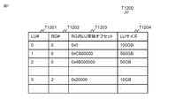
図7は、LU管理テーブルT1200の例を示している。デバイス管理テーブルT1000と同様、LU管理テーブルT1200内の各レコードそれぞれに、1つのLUについての情報が格納されている。各LUは論理ユニット番号(LUN)という一意な識別番号を有しており、LU#(T1201)にはLUの論理ユニット番号が格納される。
FIG. 7 shows an example of the LU management table T1200. Similar to the device management table T1000, information about one LU is stored in each record in the LU management table T1200. Each LU has a unique identification number called a logical unit number (LUN), and the logical unit number of the LU is stored in LU # (T1201).
先に述べたとおり、DKC10は、RAIDグループ内の連続領域をLUとして定義する。LU管理テーブルT1200には、LUが定義されているRAIDグループのRG#(T1202)、LUが定義されているRAIDグループ内のオフセットアドレス(T1203)、LUのサイズ(T1204)が格納される。
As described above, the DKC 10 defines a continuous area in the RAID group as an LU. The LU management table T1200 stores the RG # (T1202) of the RAID group in which the LU is defined, the offset address (T1203) in the RAID group in which the LU is defined, and the LU size (T1204).
続いて、FMPK200内の記憶領域の管理方法について、図8を用いて説明する。FMPK200は、DKC10に提供する記憶空間(論理アドレス空間)を、論理ページと呼ばれる所定サイズの領域単位で管理する。各論理ページを特定するために、各ページには一意な番号が付されている。この番号のことを「論理ページ番号」と呼ぶ。論理アドレス空間上の先頭に位置する論理ページの論理ページ番号が0番で、それ以降に続く論理ページには、連続した番号が付されている。論理ページのサイズは一例として、16セクタ(8KB)である。
Subsequently, a management method of the storage area in the FMPK 200 will be described with reference to FIG. The FMPK 200 manages the storage space (logical address space) provided to the DKC 10 in units of areas of a predetermined size called logical pages. In order to identify each logical page, each page is given a unique number. This number is called a “logical page number”. The logical page number of the logical page located at the head of the logical address space is 0, and successive logical pages are assigned consecutive numbers. As an example, the size of the logical page is 16 sectors (8 KB).
また、本実施例では、FMPK200内のFMチップ210に存在する記憶領域は「物理ページ」と呼ばれる。物理ページは、フラッシュメモリにおける、アクセス(リード、ライト)の最小単位である。そのためFMコントローラ201がFMチップ210に対してデータの読み書きを行う場合には、物理ページ単位での読み書きを行う。FMPK200には複数のFMチップ210が搭載され、各FMチップ210に複数の物理ページが存在しているが、FMPK200では全FMチップ210内の各物理ページに対して、ユニークな番号を付して管理している。この番号のことを「物理ページ番号」と呼ぶ。アクセス対象のデータが格納されている物理ページの物理ページ番号が特定されれば、当該物理ページが存在するFMチップ210、及びFMチップ210内位置が一意に特定できる。
In this embodiment, the storage area existing in the FM chip 210 in the FMPK 200 is called a “physical page”. A physical page is a minimum unit of access (read, write) in the flash memory. Therefore, when the FM controller 201 reads / writes data from / to the FM chip 210, it reads / writes in units of physical pages. The FMPK 200 includes a plurality of FM chips 210, and each FM chip 210 has a plurality of physical pages. In the FMPK 200, a unique number is assigned to each physical page in all the FM chips 210. I manage. This number is called a “physical page number”. If the physical page number of the physical page in which the data to be accessed is stored is specified, the FM chip 210 in which the physical page exists and the position in the FM chip 210 can be uniquely specified.
物理ページのサイズと論理ページのサイズは、同一でも良いし異なっていてもよい。本実施例では、物理ページのサイズは、528×16バイト(=8KB+256バイト)とする。論理ページのサイズ(8KB)よりも256バイト大きい理由は、各データには後述するDIF、及びECCが付加されるためである。
The physical page size and logical page size may be the same or different. In this embodiment, the size of the physical page is 528 × 16 bytes (= 8 KB + 256 bytes). The reason why the size is 256 bytes larger than the size of the logical page (8 KB) is that a DIF and ECC described later are added to each data.
先にも述べたが、FMPK200は圧縮機能を有する。FMPK200がデータを圧縮して格納する場合、FMPK200は論理ページ単位で圧縮を行う。以下、1つの論理ページ上のデータを圧縮することで生成されるデータのことを、「圧縮ページ」と呼ぶ。圧縮ページのサイズは520バイトの倍数であり、最小で520バイト、最大で(520×16)バイトである。
As described above, FMPK200 has a compression function. When the FMPK 200 compresses and stores data, the FMPK 200 performs compression in units of logical pages. Hereinafter, data generated by compressing data on one logical page is referred to as a “compressed page”. The size of the compressed page is a multiple of 520 bytes, with a minimum of 520 bytes and a maximum of (520 × 16) bytes.
圧縮により、圧縮ページのサイズは物理ページ以下になる。そのため、1つの物理ページに複数の圧縮ページを格納することが可能である。また、1つの圧縮ページが複数の物理ページに跨って格納されることもある。なお、後述するように、圧縮ページがFMチップ210に格納される際、実際には8バイトのECCが1または複数付与された状態で格納される。上で説明している圧縮ページのサイズは、ECCが付与されていない状態でのサイズである。
Compressed pages will be smaller than physical pages due to compression. Therefore, a plurality of compressed pages can be stored in one physical page. One compressed page may be stored across a plurality of physical pages. As will be described later, when a compressed page is stored in the FM chip 210, it is actually stored in a state where one or more 8-byte ECCs are assigned. The size of the compressed page described above is the size when no ECC is assigned.
図9に、FMPK200が管理するマッピングテーブルT2100の一例を示す。各行(レコード)には、各論理ページについての情報が格納される。レコードには、論理ページ番号(T2101)、物理ページ番号(T2102)、サイズ(T2103)、オフセット(T2104)の項目が含まれる。マッピングテーブルT2100は、メモリ202上に格納されている。
FIG. 9 shows an example of the mapping table T2100 managed by the FMPK 200. Each row (record) stores information about each logical page. The record includes items of logical page number (T2101), physical page number (T2102), size (T2103), and offset (T2104). The mapping table T2100 is stored on the memory 202.
論理ページ番号(T2101)には、当該レコードで管理される論理ページの論理ページ番号が格納される。物理ページ番号(T2102)には、当該レコードで管理される論理ページがマッピングされた物理ページの物理ページ番号が格納される。
The logical page number (T2101) stores the logical page number of the logical page managed by the record. The physical page number (T2102) stores the physical page number of the physical page to which the logical page managed by the record is mapped.
物理ページには、圧縮されたデータ(圧縮ページ)が格納されるため、マッピングテーブルT2100では、圧縮ページの格納されている、物理ページ内の領域を特定する情報も管理される。その情報が、サイズ(T2103)とオフセット(T2104)である。オフセット(T2104)は物理ページの先頭アドレスを0としたときの、相対アドレスが格納される。そしてオフセット(T2104)とサイズ(T2103)で特定される領域に圧縮ページが格納されることを表している。
Since the compressed data (compressed page) is stored in the physical page, the mapping table T2100 also manages information for specifying the area in the physical page where the compressed page is stored. The information is a size (T2103) and an offset (T2104). The offset (T2104) stores a relative address when the top address of the physical page is 0. The compressed page is stored in the area specified by the offset (T2104) and the size (T2103).
たとえば図9において、レコードT2100-2(論理ページ番号T2101が1000のレコード)は、論理ページ番号が1000の論理ページは、物理ページ番号(T2102)が10番の物理ページにマッピングされ、かつこの論理ページのデータ(圧縮ページ)は2KBに圧縮されていること、そして物理ページ番号(T2102)が10番の物理ページの先頭から4KBの位置から始まる2KBの大きさの領域に格納されていることを表している。
For example, in FIG. 9, in a record T2100-2 (a record with a logical page number T2101 of 1000), a logical page with a logical page number of 1000 is mapped to a physical page with a physical page number (T2102) of 10, and this logical The page data (compressed page) is compressed to 2 KB, and the physical page number (T2102) is stored in an area of 2 KB starting from the position of 4 KB from the top of the 10th physical page. Represents.
また、1つの圧縮ページが複数の物理ページに跨って格納されることもある。図9において、レコードT2100-1(論理ページ番号T2101が1のレコード)は、論理ページが、2つの物理ページにマッピングされている例を表している。レコードT2100-1で特定される論理ページ(論理ページ番号T2101が1番)は、物理ページ番号(T2102)が500番の物理ページと42番の物理ページにマッピングされている。且つ論理ページのデータは、2KB(=1KB+1KB)に圧縮されており、物理ページ番号(T2102)が500番の物理ページの先頭から7KBの位置から始まる1KBの大きさの領域、及び物理ページ番号(T2102)が42番の物理ページの先頭から0KBの位置から始まる1KBの大きさの領域に跨って格納されていることを表している。
Also, one compressed page may be stored across multiple physical pages. In FIG. 9, a record T2100-1 (a record with a logical page number T2101 of 1) represents an example in which a logical page is mapped to two physical pages. The logical page (logical page number T2101 is number 1) specified by the record T2100-1 is mapped to the physical page with the physical page number (T2102) numbered 500 and the physical page numbered 42. The logical page data is compressed to 2 KB (= 1 KB + 1 KB), the physical page number (T2102) is an area of 1 KB size starting from the position of 7 KB from the top of the 500th physical page, and the physical page number ( T2102) is stored across an area of size 1 KB starting from the position of 0 KB from the top of the 42nd physical page.
また、論理ページに対するアクセス(リード、ライト)がなかった場合には、物理ページへのマッピングは行われない。図9において、レコードT2100-0は、論理ページ(T2101が2番)に物理ページが割り当てられていない(物理ページ番号T2102がNULL)場合の、レコードの例を表している。FMPK200は、DKC10から論理ページに対するアクセスを受け付けた時点で、初めて論理ページに対して物理ページをマッピングする。
In addition, when there is no access (read, write) to the logical page, mapping to the physical page is not performed. In FIG. 9, a record T2100-0 represents an example of a record when a physical page is not allocated to a logical page (T2101 is number 2) (physical page number T2102 is NULL). The FMPK 200 maps a physical page to a logical page for the first time when access to the logical page is received from the DKC 10.
続いて、マッピングテーブルT2100以外にFMPK200が管理している情報について説明する。図10は状態管理テーブルT2000の内容を示している。状態管理テーブルT2000は、物理容量T2001、データ圧縮T2002、論理容量T2003、接続DKC種別T2004、所属RAIDグループ構成T2005、RAIDグループ内位置T2006、所属RAIDグループ番号(所属RG#)T2007の項目を有している。
Subsequently, information managed by the FMPK 200 in addition to the mapping table T2100 will be described. FIG. 10 shows the contents of the state management table T2000. The state management table T2000 includes items of physical capacity T2001, data compression T2002, logical capacity T2003, connection DKC type T2004, belonging RAID group configuration T2005, RAID group position T2006, and belonging RAID group number (affiliation RG #) T2007. ing.
物理容量T2001は、FMPK200の有するFMチップ210の合計記憶容量である。データ圧縮T2002には「有」または「無」のいずれかの情報が格納され、「有」が格納されている場合には、FMPK200はDKC10からのライトデータを圧縮してFMチップ210に格納する。データ圧縮T2002の設定は、DKC10がFMPK200を用いてRAIDグループを定義する時等に、DKC10(または管理者)が「有」または「無」を設定する。
The physical capacity T2001 is the total storage capacity of the FM chip 210 that the FMPK 200 has. The data compression T2002 stores either “Yes” or “No” information. If “Yes” is stored, the FMPK 200 compresses the write data from the DKC 10 and stores it in the FM chip 210. . The data compression T2002 is set such that the DKC 10 (or the administrator) sets “present” or “not present” when the DKC 10 uses the FMPK 200 to define a RAID group.
論理容量T2003は、FMPK200がDKC10に提供しているアドレス空間の容量である。FMPK200にデータが圧縮されずに格納される場合には、原則として物理容量T2001の値と論理容量T2003の値は等しい。FMPK200にデータが圧縮されて格納される場合には、論理容量T2003の値は物理容量T2001より大きくなる。DKC10(または管理者)により、データ圧縮T2002には「有」が設定されると、FMPK200は論理容量T2003に仮の値(たとえば物理容量T2001の8倍の値等)を格納し、DKC10に対して、仮の値と等しいサイズの記憶空間を提供する。またデータがFMチップ210に格納されていくにしたがって、論理容量T2003に等しい量のデータを格納できないとFMPK200が判断した場合には、論理容量T2003のサイズを小さくする等を行ってよい。逆に、圧縮によりデータサイズが予想以上に小さくなったために、論理容量T2003よりも多い量のデータを格納できるとFMPK200が判断した場合、論理容量T2003のサイズを大きくする等の処理を行ってよい。
The logical capacity T2003 is the capacity of the address space provided by the FMPK 200 to the DKC 10. When data is stored in the FMPK 200 without being compressed, in principle, the value of the physical capacity T2001 and the value of the logical capacity T2003 are equal. When data is compressed and stored in the FMPK 200, the value of the logical capacity T2003 is larger than the physical capacity T2001. When “present” is set in the data compression T2002 by the DKC 10 (or the administrator), the FMPK 200 stores a temporary value (for example, a value that is eight times the physical capacity T2001) in the logical capacity T2003. Thus, a storage space having a size equal to the temporary value is provided. If the FMPK 200 determines that the amount of data equal to the logical capacity T2003 cannot be stored as the data is stored in the FM chip 210, the size of the logical capacity T2003 may be reduced. Conversely, if the FMPK 200 determines that a larger amount of data than the logical capacity T2003 can be stored because the data size has become smaller than expected due to compression, processing such as increasing the size of the logical capacity T2003 may be performed. .
接続DKC種別T2004は、FMPK200が接続されているストレージシステム1の種別(機種名等)が格納される。FMPK200がストレージシステム1に接続されたことを契機に、DKC10からストレージシステム1の種別についての情報がFMPK200に渡される。FMPK200は渡された情報を接続DKC種別T2004に格納する。
The connection DKC type T2004 stores the type (model name, etc.) of the storage system 1 to which the FMPK 200 is connected. When the FMPK 200 is connected to the storage system 1, information about the type of the storage system 1 is passed from the DKC 10 to the FMPK 200. The FMPK 200 stores the passed information in the connection DKC type T2004.
所属RAIDグループ構成T2005、RAIDグループ内位置T2006、所属RG#(T2007)は、FMPKが所属するRAIDグループについての情報で、RG管理情報T1100に格納されているRAID構成T1003,所属デバイス#(T1102)、RG#(T1101)の情報と同様の情報が格納される。これらの情報は、DKC10がFMPK200を用いてRAIDグループを定義する際に、DKC10からFMPK200に通知される。
The belonging RAID group configuration T2005, the RAID group internal position T2006, and the belonging RG # (T2007) are information about the RAID group to which the FMPK belongs, and the RAID configuration T1003 and the belonging device # (T1102) stored in the RG management information T1100. , Information similar to the information of RG # (T1101) is stored. These pieces of information are notified from the DKC 10 to the FMPK 200 when the DKC 10 uses the FMPK 200 to define the RAID group.
続いて、保証コードについて説明する。ストレージコントローラ(DKC)10は、ホスト2から受信したライトデータをFMPK200に格納する過程で、エラー検出用の情報である検証用情報を付加して、データとこの検証用情報とをドライブ121に格納する。なお、この検証用情報は、ホスト2が論理ユニットにアクセスする際の最小アクセス単位である、1ディスクブロック(1セクタともいう。また1ディスクブロック(セクタ)のサイズは、一般的には512バイトであり、本実施例のストレージシステム1においても、1ディスクブロック(セクタ)のサイズは512バイトとする)ごとに付加される。以下ではこの検証用情報のことをDIFと呼ぶ。
Next, the warranty code will be explained. In the process of storing the write data received from the host 2 in the FMPK 200, the storage controller (DKC) 10 adds verification information that is error detection information, and stores the data and the verification information in the drive 121. To do. This verification information is one disk block (also called one sector) which is the minimum access unit when the host 2 accesses the logical unit. The size of one disk block (sector) is generally 512 bytes. In the storage system 1 of this embodiment, the size of one disk block (sector) is 512 bytes). Hereinafter, this verification information is referred to as DIF.
さらにFMPK200内でも、データに更なる検証用情報を付加する処理が行われる。以下では、DKC10がデータに付加する検証用情報の事を「DKC-DIF」と呼び、FMPK200内でFMPK200がデータに付加する検証用情報のことを「PK-DIF」と呼ぶ。また両者を区別せずに呼ぶ場合には、「DIF」と表記される。また、FMPK200がFMチップ210にデータを格納する際にも、更なる検証用情報を付加するが、この検証用情報のことは「ECC」と呼ばれる。
Further, processing for adding further verification information to the data is also performed in the FMPK 200. Hereinafter, the verification information added to the data by the DKC 10 is called “DKC-DIF”, and the verification information added to the data by the FMPK 200 in the FMPK 200 is called “PK-DIF”. Also, when calling the two without distinction, “DIF” is written. Further, when the FMPK 200 stores data in the FM chip 210, further verification information is added. This verification information is called “ECC”.
図11を用いて、DKC-DIF、PK-DIFについて説明する。図11は、ホスト2からのライトデータにDIFが付加される過程を表した概念図である。ホスト2からライトデータ500がストレージシステム1に到来すると、DKC(ストレージコントローラ)10はFMPK200に当該ライトデータを送信する前に、DKC-DIF511を付加する。ライトデータ501は、FMPK200に送信される直前の、ライトデータの状態(DKC-DIF511が付加されている状態)を表している。DKC10は1セクタ(512バイト)毎にDKC-DIF511を付加し、FMPK200に対して、DKC-DIF511の付加されたライトデータ501を送信する。
DKC-DIF and PK-DIF will be described with reference to FIG. FIG. 11 is a conceptual diagram showing a process in which DIF is added to write data from the host 2. When write data 500 arrives at the storage system 1 from the host 2, the DKC (storage controller) 10 adds a DKC-DIF 511 before transmitting the write data to the FMPK 200. Write data 501 represents the state of the write data (the state in which the DKC-DIF 511 is added) immediately before being transmitted to the FMPK 200. The DKC 10 adds a DKC-DIF 511 for each sector (512 bytes), and transmits the write data 501 with the DKC-DIF 511 added to the FMPK 200.
続いてFMPK200内でのデータの流れについて説明する。以下では特に、FMPK200でデータが圧縮される場合について説明する。この場合、SAS-CTL206に到着したデータ(ライトデータ501)は、圧縮伸長回路204へと渡される。ライトデータ502は、SAS-CTL206から圧縮伸長回路204に渡されるデータの形式を表している。SAS-CTL206が圧縮伸長回路204にデータを渡す際、1セクタ分のライトデータ毎に、PK-DIF521を付加する。
Next, the data flow in the FMPK 200 will be described. Hereinafter, a case where data is compressed by the FMPK 200 will be described in particular. In this case, the data (write data 501) arriving at the SAS-CTL 206 is passed to the compression / decompression circuit 204. Write data 502 represents the format of data passed from the SAS-CTL 206 to the compression / decompression circuit 204. When the SAS-CTL 206 delivers data to the compression / decompression circuit 204, a PK-DIF 521 is added for each write data of one sector.
ここで、DKC-DIF及びPK-DIFに含まれる情報について説明する。1セクタ(512バイト)のデータに対して付されるDKC-DIF511のサイズは、8バイトである。DKC-DIF511には、CRC(Cyclic Redundancy Check)、RAIDグループ番号、シーケンス番号、アドレス情報が含まれる。
Here, information included in DKC-DIF and PK-DIF will be described. The size of the DKC-DIF 511 attached to the data of one sector (512 bytes) is 8 bytes. The DKC-DIF 511 includes a CRC (Cyclic Redundancy Check), a RAID group number, a sequence number, and address information.
CRCは、データ510に所定の演算を施して生成される情報である。SAS-CTL206がDKC10から、DKC-DIF511の付加されたライトデータ501を受信すると、データ510に所定の演算を施してCRCを算出する。そして算出されたCRCと、DKC-DIF511内のCRCとが一致するか判定する(以下、この判定のことを「CRCチェック」と呼ぶ)。両者が一致しない場合、DKC10からSAS-CTL206にデータが転送されてくる過程で、障害等の要因でデータ内容が変更されたことを意味する。そのため両者が一致しなかった場合には、DKC10にエラーを返却し、ライトデータ501の書き込み処理を中断する。
CRC is information generated by performing a predetermined operation on the data 510. When the SAS-CTL 206 receives the write data 501 to which the DKC-DIF 511 is added from the DKC 10, it performs a predetermined operation on the data 510 to calculate a CRC. Then, it is determined whether the calculated CRC matches the CRC in the DKC-DIF 511 (hereinafter, this determination is referred to as “CRC check”). If they do not match, it means that the data content has been changed due to a failure or the like in the process of transferring data from the DKC 10 to the SAS-CTL 206. For this reason, if they do not match, an error is returned to the DKC 10 and the write processing of the write data 501 is interrupted.
アドレス情報は、データ510の書き込まれるFMPK200上の論理記憶空間上のアドレスである(またはアドレスの一部がアドレス情報に含まれる。たとえばアドレスが4バイトを超えるものである場合、アドレスの下位4バイトのみがアドレス情報として用いられる)。SAS-CTL206が、DKC10からDKC-DIF511の付加されたライトデータ501を受信する場合、それとともにライトデータ501をFMPK200に格納することを指示する命令(いわゆるWRITEコマンド)も受信する。WRITEコマンドにも、データ510の書き込み先である、FMPK200上の論理記憶空間上のアドレス情報が含まれているので、SAS-CTL206はDIFに含まれる内のアドレス情報と、WRITEコマンドに含まれているアドレス情報とが一致するか判定する。両者が一致しない場合には、FMPK200はDKC10にエラーを返却し、ライトデータ501の書き込み処理を中断する。
The address information is an address in the logical storage space on the FMPK 200 in which the data 510 is written (or a part of the address is included in the address information. For example, when the address exceeds 4 bytes, the lower 4 bytes of the address Only used as address information). When the SAS-CTL 206 receives the write data 501 to which the DKC-DIF 511 is added from the DKC 10, it also receives a command (so-called WRITE command) instructing to store the write data 501 in the FMPK 200. Since the WRITE command also includes address information in the logical storage space on the FMPK 200 that is the write destination of the data 510, the SAS-CTL 206 is included in the address information included in the DIF and the WRITE command. It is determined whether the address information matches. If they do not match, the FMPK 200 returns an error to the DKC 10 and interrupts the write processing of the write data 501.
RAIDグループ番号は、データ510の書き込まれるFMPK200が所属するRAIDグループの番号(RG#)である。FMPK200はDKC10からあらかじめ、自身が所属するRAIDグループの番号の情報を受信している。そのため、SAS-CTL206が、DKC10からDKC-DIF511の付加されたライトデータ501を受信すると、DKC-DIF511に含まれているRAIDグループ番号と、あらかじめ受信しているRAIDグループ番号とを比較することができる。両者が一致しない場合、FMPK200はDKC10にエラーを返却し、ライトデータ501の書き込み処理を中断する。
The RAID group number is a RAID group number (RG #) to which the FMPK 200 to which the data 510 is written belongs. The FMPK 200 has previously received information on the number of the RAID group to which the FMPK 200 belongs from the DKC 10. Therefore, when the SAS-CTL 206 receives the write data 501 to which the DKC-DIF 511 is added from the DKC 10, it can compare the RAID group number included in the DKC-DIF 511 with the RAID group number received in advance. it can. If they do not match, the FMPK 200 returns an error to the DKC 10 and interrupts the write processing of the write data 501.
シーケンス番号は一種の連続番号である。DKC10がFMPK200に複数セクタ分のデータを書き込む際、隣り合うデータ510に付されるDKC-DIF511には、連続したシーケンス番号が格納されている。たとえばDKC10が10セクタ分のデータを書き込む場合、先頭のデータ510に付与されるDKC-DIF511には、シーケンス番号0が格納され、次のデータ510に付与されるDKC-DIF511には、シーケンス番号1が格納されている。そのため、連続した複数セクタのデータがライト(またはリード)される時、SAS-CTL206は隣り合ったセクタのシーケンス番号が連続番号であるか判定する。連続番号が付されていない場合には、FMPK200はDKC10にエラーを返却し、ライトデータ501の書き込み処理を中断する。
The sequence number is a kind of serial number. When the DKC 10 writes data for a plurality of sectors to the FMPK 200, consecutive sequence numbers are stored in the DKC-DIF 511 attached to the adjacent data 510. For example, when the DKC 10 writes data for 10 sectors, the sequence number 0 is stored in the DKC-DIF 511 assigned to the first data 510, and the sequence number 1 is stored in the DKC-DIF 511 assigned to the next data 510. Is stored. Therefore, when data of a plurality of consecutive sectors is written (or read), the SAS-CTL 206 determines whether the sequence numbers of adjacent sectors are consecutive numbers. If the serial number is not assigned, the FMPK 200 returns an error to the DKC 10 and interrupts the write processing of the write data 501.
PK-DIF521にも同様に、データから算出されたCRCが含まれる。PK-DIF521に含まれるCRCは、データ510とDKC-DIF511で構成される520バイトのデータから算出されるCRCである。
Similarly, the PK-DIF 521 includes a CRC calculated from the data. The CRC included in the PK-DIF 521 is a CRC calculated from 520-byte data composed of the data 510 and the DKC-DIF 511.
図11の説明に戻る。圧縮伸長回路204に対して、DKC-DIF511、PK-DIF521の付加されたデータが渡されると、圧縮伸長回路204はデータ圧縮を行う。なお、先に述べたとおり、圧縮は1論理ページ分のデータ毎に行われる。また圧縮の際、データ510に付加されているDKC-DIF511とPK-DIF521も併せて圧縮される。つまり圧縮伸長回路204は、「データ510とDKC-DIF511とPK-DIF521」のセットを16個まとめて圧縮する。なお圧縮伸長回路204は、サイズが520バイトの倍数になるように圧縮データを生成する。
Returning to the explanation of FIG. When the data to which the DKC-DIF 511 and the PK-DIF 521 are added is passed to the compression / decompression circuit 204, the compression / decompression circuit 204 performs data compression. As described above, the compression is performed for each data of one logical page. At the time of compression, the DKC-DIF 511 and the PK-DIF 521 added to the data 510 are also compressed. That is, the compression / decompression circuit 204 compresses 16 sets of “data 510, DKC-DIF 511, and PK-DIF 521” together. The compression / decompression circuit 204 generates the compressed data so that the size is a multiple of 520 bytes.
圧縮データ530-0が生成されると、圧縮伸長回路204は圧縮データ530-0にPK-DIF531を付加する。PK-DIF531は、520バイトのデータ(圧縮されたデータ)ごとに付される。PK-DIF531はPK-DIF521と同様に、データ(圧縮データ530-0)から算出されたCRCを含んでいる。また圧縮伸長回路204は、圧縮を行う前に、データ510とDKC-DIF511からCRCを算出する。そして算出されたCRCとPK-DIF521に含まれるCRCとが一致するか判定する。両者が一致しない場合にはDKC10にエラーを返却し、ライトデータ501の書き込み処理を中断する。
When the compressed data 530-0 is generated, the compression / decompression circuit 204 adds the PK-DIF 531 to the compressed data 530-0. The PK-DIF 531 is attached for each 520-byte data (compressed data). Similar to the PK-DIF 521, the PK-DIF 531 includes a CRC calculated from the data (compressed data 530-0). The compression / decompression circuit 204 calculates a CRC from the data 510 and the DKC-DIF 511 before performing compression. Then, it is determined whether the calculated CRC matches the CRC included in the PK-DIF 521. If they do not match, an error is returned to the DKC 10 and the write processing of the write data 501 is interrupted.
圧縮伸長回路204により生成された、圧縮データ530-0及びそのPK-DIF531は、FM-IF207を経由してFMチップ210に書き込まれる。FM-IF207に圧縮データ530-0及びそのPK-DIF531が到来すると、FM-IF207はPK-DIF531に含まれているCRCのチェックを行う。チェック方法は圧縮伸長回路204で行われているものと同様で、圧縮データ530-0からCRCを算出し、算出されたCRCとPK-DIF531に含まれているCRCが一致するか判定する。両者が一致しない場合、DKC10にエラーを返却し、ライトデータ501の書き込み処理を中断する。
The compressed data 530-0 and its PK-DIF 531 generated by the compression / decompression circuit 204 are written into the FM chip 210 via the FM-IF 207. When the compressed data 530-0 and its PK-DIF 531 arrive at the FM-IF 207, the FM-IF 207 checks the CRC included in the PK-DIF 531. The check method is the same as that performed by the compression / decompression circuit 204. CRC is calculated from the compressed data 530-0, and it is determined whether the calculated CRC matches the CRC included in the PK-DIF531. If they do not match, an error is returned to the DKC 10 and the write processing of the write data 501 is interrupted.
CRCのチェックでエラーが発生しなかった場合には、FM-IF207は圧縮データ530-0に付与されているPK-DIF531を除去する。そして圧縮データ530-0から別のエラーチェックコードを生成する。このエラーチェックコードは「ECC」と呼ばれる。ECC541はPK-DIF531と同様、520バイトの圧縮データ530-0毎に付与される。そしてFM-IF207は、ECC541の付与された圧縮データ530-0をFMチップ210に書き込む。
If no error occurs in the CRC check, the FM-IF 207 removes the PK-DIF 531 attached to the compressed data 530-0. Then, another error check code is generated from the compressed data 530-0. This error check code is called “ECC”. The ECC 541 is provided for each 520-byte compressed data 530-0, as in the PK-DIF 531. The FM-IF 207 writes the compressed data 530-0 assigned with the ECC 541 to the FM chip 210.
データがFMチップ210から読み出される場合には、上で説明した処理と逆の処理が行われる。FM-IF207がFMチップ210から、ECC541の付加された圧縮データ530-0を読み出し、ECC541のチェックを行う(圧縮データ530-0から算出されたECCと、ECC541の比較を行う)。その後ECC541を圧縮データ530-0から除去して、PK-DIF531を付与し、圧縮伸長回路204へPK-DIF531の付与された圧縮データ530-0が渡される。圧縮伸長回路204では、PK-DIF531に含まれるCRCのチェックを行い、その後圧縮データ530-0を伸長し、「データ510とDKC-DIF511とPK-DIF521」のセットを(1または複数)生成する。
When data is read from the FM chip 210, the reverse process to the process described above is performed. The FM-IF 207 reads the compressed data 530-0 to which the ECC 541 is added from the FM chip 210, and checks the ECC 541 (compares the ECC calculated from the compressed data 530-0 with the ECC 541). Thereafter, the ECC 541 is removed from the compressed data 530-0, the PK-DIF 531 is added, and the compressed data 530-0 to which the PK-DIF 531 is added is passed to the compression / decompression circuit 204. The compression / decompression circuit 204 checks the CRC included in the PK-DIF 531, and then decompresses the compressed data 530-0 to generate a set (one or a plurality) of “data 510, DKC-DIF 511, and PK-DIF 521”. .
生成された「データ510とDKC-DIF511とPK-DIF521」のセットが、SAS-CTL206を経由してDKC10に転送される際、SAS-CTL206は、PK-DIF521に含まれるCRCのチェックを行い、その後「データ510とDKC-DIF511とPK-DIF521」のセットからPK-DIF521を除去し、データ510とDKC-DIF511をDKC10へと転送する。
When the generated set of “data 510, DKC-DIF 511, and PK-DIF 521” is transferred to the DKC 10 via the SAS-CTL 206, the SAS-CTL 206 checks the CRC included in the PK-DIF 521, Thereafter, the PK-DIF 521 is removed from the set of “data 510, DKC-DIF 511, and PK-DIF 521”, and the data 510 and DKC-DIF 511 are transferred to the DKC 10.
上で説明したデータの流れは、データが圧縮伸長回路204によって圧縮される場合の例である。ただしFMPK200は、データを圧縮せずにFMチップ210に格納することもできる。その場合には、SAS-CTL206でPK-DIF521の付加されたデータ510は圧縮伸長回路204を経由せずにFM-IF207に渡される。FM-IF207では、データ510及びそのDKC-DIF511とPK-DIF521が到来すると、PK-DIF521に含まれているCRCのチェックを行う。チェック方法は上で説明したものと同様である。
The data flow described above is an example when the data is compressed by the compression / decompression circuit 204. However, the FMPK 200 can store the data in the FM chip 210 without compressing the data. In that case, the data 510 to which the PK-DIF 521 is added by the SAS-CTL 206 is passed to the FM-IF 207 without passing through the compression / decompression circuit 204. When the data 510 and its DKC-DIF 511 and PK-DIF 521 arrive, the FM-IF 207 checks the CRC included in the PK-DIF 521. The checking method is the same as described above.
その後FM-IF207は、PK-DIF521の付加されたデータ510からPK-DIF521を除去し、ECCを生成して付加する。ここでのECCは、データ510とDKC-DIF511で構成される520バイトのデータから生成されるものである。そしてECCの付加されたデータ510及びDKC-DIF511をFMチップ210に格納する。
After that, the FM-IF 207 removes the PK-DIF 521 from the data 510 to which the PK-DIF 521 is added, generates an ECC, and adds it. The ECC here is generated from 520-byte data composed of data 510 and DKC-DIF 511. Then, the data 510 with the ECC added and the DKC-DIF 511 are stored in the FM chip 210.
なお、上で説明したDKC-DIF511、PK-DIF521、PK-DIF531に含まれる情報は一例であって、上で説明した以外の検証用情報が含まれるようにしてもよい。またDKC-DIF511は、FMPK200が接続されるDKC10によって付加される情報であるので、DKC10の種類(機種)によって、DKC-DIF511のフォーマットが異なる場合がある。たとえばCRCやアドレス情報の長さがDKC10の種類によって異なっている場合があり得る。またDKC-DIF511内における、アドレス情報、シーケンス番号、CRCの並び順がDKC10の種類によって異なっていることもあり得る。本実施例に係るFMPK200は、各機種(DKC)のDKC-DIFのフォーマットについての情報(CRCやアドレス情報の格納されている位置など)を把握している。また接続されるDKCから、DKCの種類(機種)情報を受信することで、CRC,アドレス情報、シーケンス番号、RAIDグループ番号の格納位置を認識可能に構成されている。
Note that the information included in the DKC-DIF 511, PK-DIF 521, and PK-DIF 531 described above is an example, and verification information other than that described above may be included. Since the DKC-DIF 511 is information added by the DKC 10 to which the FMPK 200 is connected, the format of the DKC-DIF 511 may differ depending on the type (model) of the DKC 10. For example, the length of CRC or address information may vary depending on the type of DKC 10. Further, the address information, sequence number, and CRC arrangement order in the DKC-DIF 511 may differ depending on the type of the DKC 10. The FMPK 200 according to the present embodiment grasps information about the DKC-DIF format of each model (DKC) (such as a location where CRC and address information are stored). Further, by receiving DKC type (model) information from the connected DKC, the storage location of the CRC, address information, sequence number, and RAID group number can be recognized.
続いて、FMPK200がサポートするコマンドの種類と、コマンドのフォーマットについて説明する。FMPK200は、DKC10等の上位装置からコマンドを受信し、受信したコマンドに含まれている指示情報(パラメータ)の内容に従った処理(データのリード、ライト等)を行う。FMPK200は、SSDやHDD等の周知の記憶デバイスと同様、データの読み出しを指示するリードコマンド、データの書き込みを指示するライトコマンドもサポートしているが、それ以外のコマンドもサポートしている。ここではFMPK200でサポートされているコマンドのうち、本実施例で行われるデータ復旧処理で用いられるコマンドの内容について説明する。以下、FMPK200にコマンドを発行する発行元の装置は、DKC10であるという前提で説明する。
Next, the types of commands supported by the FMPK 200 and the command format will be described. The FMPK 200 receives a command from a higher-level device such as the DKC 10, and performs processing (data read, write, etc.) according to the content of the instruction information (parameter) included in the received command. The FMPK 200 supports a read command for instructing data reading and a write command for instructing data writing, as well as known storage devices such as SSDs and HDDs, but also supports other commands. Here, of the commands supported by the FMPK 200, the contents of commands used in the data recovery process performed in the present embodiment will be described. Hereinafter, description will be made on the assumption that the issuing device that issues a command to the FMPK 200 is the DKC 10.
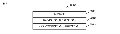
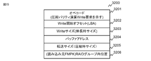
[圧縮Readコマンド]
このコマンドは、リードデータを圧縮された状態で、DKC10等のコマンド発行元に対して返却することを指示するためのコマンドである。圧縮Readコマンドに含まれているパラメータについて図12を用いて説明する。 [Compressed Read command]
This command is a command for instructing the command issuer such as theDKC 10 to return the read data in a compressed state. The parameters included in the compressed Read command will be described with reference to FIG.
このコマンドは、リードデータを圧縮された状態で、DKC10等のコマンド発行元に対して返却することを指示するためのコマンドである。圧縮Readコマンドに含まれているパラメータについて図12を用いて説明する。 [Compressed Read command]
This command is a command for instructing the command issuer such as the
圧縮Readコマンド3000には、オペコード(Opcode)3001、Read開始オフセット3002、Readサイズ3003、バッファアドレス3004、転送サイズ3005、のパラメータが含まれる。オペコード(Opcode)3001は、FMPK200がサポートする全コマンドに共通に含まれている情報で(ただしオペコード3001に含まれている情報の内容は、コマンドによって異なる)、FMPK200は受信したコマンドのオペコード3001を参照することで、受信したコマンドの種類を識別する。当然ながら、圧縮Readコマンド3000に含まれているオペコード3001には、圧縮Readコマンドであることが識別できる情報が格納されている。
The compressed read command 3000 includes parameters of an opcode 3001, a read start offset 3002, a read size 3003, a buffer address 3004, and a transfer size 3005. The operation code (Opcode) 3001 is information included in all commands supported by the FMPK 200 (however, the content of the information included in the operation code 3001 varies depending on the command). The FMPK 200 stores the operation code 3001 of the received command. By referring, the type of the received command is identified. Of course, the opcode 3001 included in the compressed read command 3000 stores information that can be identified as the compressed read command.
Read開始オフセット3002、Readサイズ3003は、DKC10がリードしたいデータ(リード対象データ)が格納されている、FMPK200上の論理アドレス空間上の領域を特定するための情報である。Read開始オフセット3002には、リード対象データの格納されている、FMPK200上の論理アドレス空間上領域の先頭アドレスが、Readサイズ3003にはリード対象データのサイズが指定される。本実施例では、アドレスを特定する情報として、論理ブロックアドレス(LBA)が用いられる。ただし別の実施形態として、アドレスを特定する情報として、論理ページ番号を用いてもよい。またReadサイズ3003には、セクタ数が指定される。ただし別の実施形態として、他の単位(たとえば論理ページ数、バイト数等)が指定されるようにしてもよい。またReadサイズ3003には、FMPK200内でデータが圧縮されて格納されている、いないにかかわらず、非圧縮時のデータサイズが指定される。
The Read start offset 3002 and the Read size 3003 are information for specifying an area in the logical address space on the FMPK 200 in which data (read target data) that the DKC 10 wants to read is stored. The read start offset 3002 specifies the start address of the logical address space area on the FMPK 200 where the read target data is stored, and the read size 3003 specifies the size of the read target data. In this embodiment, a logical block address (LBA) is used as information for specifying an address. However, as another embodiment, a logical page number may be used as information for specifying an address. Also, the read size 3003 specifies the number of sectors. However, as another embodiment, other units (for example, the number of logical pages, the number of bytes, etc.) may be specified. In addition, the read size 3003 specifies the data size at the time of non-compression regardless of whether the data is compressed and stored in the FMPK 200.
バッファアドレス3004、転送サイズ3005は、リード対象データの転送先の領域(領域の先頭アドレスと領域のサイズ)を特定する情報であり、DKC10がFMPK200に圧縮Readコマンド3000を発行する場合には、バッファアドレス3004にはバッファ131のアドレスを指定する。
The buffer address 3004 and the transfer size 3005 are information for specifying the transfer destination area (the start address of the area and the size of the area) of the read target data. When the DKC 10 issues the compressed Read command 3000 to the FMPK 200, the buffer address The address 3004 designates the address of the buffer 131.
FMPK200は、DKC10から圧縮Readコマンド3000を受信すると、圧縮状態のリードデータをDKC10に転送(DKC10の、バッファアドレス3004、転送サイズ3005で特定されるバッファ131上領域に転送)するとともに、応答情報をDKC10に返却する。応答情報には、受信したコマンドに係る処理が正常に行われたか否かを表す情報や、サイズについての情報が含まれる。圧縮Readコマンド3000に対する応答情報のフォーマットについて、図13を用いて説明する。
When the FMPK 200 receives the compressed Read command 3000 from the DKC 10, the FMPK 200 transfers the compressed read data to the DKC 10 (transfers it to the area on the buffer 131 specified by the buffer address 3004 and the transfer size 3005 of the DKC 10), and response information. Return to DKC10. The response information includes information indicating whether or not the processing related to the received command has been normally performed, and information about the size. The format of response information for the compressed Read command 3000 will be described with reference to FIG.
圧縮Readコマンド3000に対する応答情報には、転送結果3011、Readサイズ3012、バッファ使用サイズ3013が含まれる。転送結果3011には、「成功」または「エラー」の情報が含まれており、転送結果3011が「成功」の場合には、圧縮Readコマンド3000に係る処理が正常に行われたことを意味する。
The response information to the compressed read command 3000 includes a transfer result 3011, a read size 3012, and a buffer use size 3013. The transfer result 3011 includes information of “success” or “error”. When the transfer result 3011 is “success”, it means that the processing related to the compressed read command 3000 has been normally performed. .
Readサイズ3012には、リード対象データのサイズ(非圧縮時)が格納される。原則として、圧縮Readコマンド3000のReadサイズ3003と同じ値が格納されている。またバッファ使用サイズ3013には、DKC10に転送された、圧縮状態のリードデータのサイズが格納される。
The read size 3012 stores the size of the read target data (when not compressed). In principle, the same value as the read size 3003 of the compressed read command 3000 is stored. In the buffer use size 3013, the size of the read data in the compressed state transferred to the DKC 10 is stored.
[圧縮コピーWriteコマンド]
このコマンドは、DKC10が先に説明した圧縮Readコマンド3000を用いて、FMPK200から読み出したデータ(圧縮状態)を、FMPK200に格納する際に用いられる。圧縮コピーWriteコマンドに含まれているパラメータについて、図14を用いて説明する。 [Compressed copy write command]
This command is used when the data (compressed state) read from theFMPK 200 is stored in the FMPK 200 by using the compression read command 3000 described above by the DKC 10. The parameters included in the compressed copy write command will be described with reference to FIG.
このコマンドは、DKC10が先に説明した圧縮Readコマンド3000を用いて、FMPK200から読み出したデータ(圧縮状態)を、FMPK200に格納する際に用いられる。圧縮コピーWriteコマンドに含まれているパラメータについて、図14を用いて説明する。 [Compressed copy write command]
This command is used when the data (compressed state) read from the
圧縮コピーWriteコマンド3100には、オペコード(Opcode)3101、Write開始オフセット3102、Writeサイズ3103、転送元アドレス3104、転送サイズ3105、のパラメータが含まれる。オペコード(Opcode)3101は、圧縮Readコマンドの説明の際に述べたとおり、受信したコマンドの種類をFMPK200が識別するための情報が含まれている。
The compressed copy write command 3100 includes parameters of an opcode 3101, a write start offset 3102, a write size 3103, a transfer source address 3104, and a transfer size 3105. The operation code (Opcode) 3101 includes information for the FMPK 200 to identify the type of the received command as described in the description of the compressed Read command.
Write開始オフセット3102、Writeサイズ3103は、ライト対象データの書き込み先の領域を特定するための情報で、Write開始オフセット3102には、ライト対象データの書き込み先となる、(FMPK200が提供する)論理アドレス空間の先頭アドレスが、Writeサイズ3103にはライト対象データのサイズが指定される。なお、圧縮コピーWriteコマンド3100が発行される時、DKC10から圧縮されたデータがFMPK200に送信されるが、ここで指定されるWrite開始オフセット3102、Writeサイズ3103は、非圧縮時のライトデータの格納される領域(論理アドレス空間上の領域)が指定される。
The write start offset 3102 and the write size 3103 are information for specifying the write destination area of the write target data. The write start offset 3102 is a logical address (provided by the FMPK 200) that is the write destination of the write target data. The space start address is the write size 3103, and the write target data size is specified. Note that when the compressed copy write command 3100 is issued, the compressed data is transmitted from the DKC 10 to the FMPK 200. The write start offset 3102 and the write size 3103 specified here are used to store write data when not compressed. Area (area on the logical address space) is designated.
転送元アドレス3104、転送サイズ3105は、FMPK200に転送すべき、圧縮状態のライト対象データが格納されている領域を特定するための情報である。通常、DKC10が圧縮コピーWriteコマンド3100をFMPK200に発行する際、ライト対象データはバッファ131に格納されている。そのため転送元アドレス3104、転送サイズ3105にはそれぞれ、バッファ131上の圧縮状態のライト対象データが格納されている領域の先頭アドレス、圧縮状態のライト対象データのサイズが指定される。
The transfer source address 3104 and the transfer size 3105 are information for specifying an area in which the compressed write target data to be transferred to the FMPK 200 is stored. Normally, when the DKC 10 issues the compressed copy write command 3100 to the FMPK 200, the write target data is stored in the buffer 131. For this reason, the source address 3104 and the transfer size 3105 specify the start address of the area where the write target data in the compressed state in the buffer 131 is stored and the size of the write target data in the compressed state, respectively.
圧縮コピーWriteコマンド3100に対する応答情報は、図16に示されているように、転送結果3011のみが含まれている。転送結果3011は、圧縮Readコマンド3000に対する応答情報に含まれている転送結果3011と同じである。つまり「成功」または「エラー」の情報が含まれている。転送結果3011が「成功」の場合には、圧縮コピーWriteコマンド3100に係る処理が正常に行われたことを意味する。
The response information to the compressed copy write command 3100 includes only the transfer result 3011 as shown in FIG. The transfer result 3011 is the same as the transfer result 3011 included in the response information for the compressed Read command 3000. That is, “success” or “error” information is included. When the transfer result 3011 is “successful”, it means that the processing related to the compressed copy write command 3100 has been normally performed.
[圧縮パリティ演算Writeコマンド]
このコマンドは、DKC10が先に説明した圧縮Readコマンド3000を用いて、FMPK200から読み出したデータ(圧縮状態)を、FMPK200に送信するとともに、FMPK200に対し、送信したデータを用いて冗長データ(パリティ)を算出することを指示するためのコマンドである。なお、以下では、圧縮パリティ演算WriteコマンドとともにFMPK200に送信されるデータ(FMPK200から読み出した圧縮状態のデータ)のことを「ライト対象データ」と呼ぶ。圧縮パリティ演算Writeコマンドに含まれているパラメータについて、図15を用いて説明する。 [Compressed parity operation Write command]
This command transmits data (compressed state) read from theFMPK 200 to the FMPK 200 using the compressed read command 3000 described earlier by the DKC 10 and redundant data (parity) using the transmitted data to the FMPK 200. This is a command for instructing to calculate. Hereinafter, data transmitted to the FMPK 200 together with the compressed parity calculation Write command (compressed data read from the FMPK 200) is referred to as “write target data”. The parameters included in the compressed parity calculation Write command will be described with reference to FIG.
このコマンドは、DKC10が先に説明した圧縮Readコマンド3000を用いて、FMPK200から読み出したデータ(圧縮状態)を、FMPK200に送信するとともに、FMPK200に対し、送信したデータを用いて冗長データ(パリティ)を算出することを指示するためのコマンドである。なお、以下では、圧縮パリティ演算WriteコマンドとともにFMPK200に送信されるデータ(FMPK200から読み出した圧縮状態のデータ)のことを「ライト対象データ」と呼ぶ。圧縮パリティ演算Writeコマンドに含まれているパラメータについて、図15を用いて説明する。 [Compressed parity operation Write command]
This command transmits data (compressed state) read from the
圧縮パリティ演算Writeコマンド3200には、オペコード(Opcode)3201、Write開始オフセット3202、Writeサイズ3203、バッファアドレス3204、転送サイズ3205、RAIDグループ内位置3206、のパラメータが含まれる。
The compressed parity calculation write command 3200 includes parameters of an opcode 3201, a write start offset 3202, a write size 3203, a buffer address 3204, a transfer size 3205, and a RAID group position 3206.
オペコード(Opcode)3201は、受信したコマンドの種類をFMPK200が識別するための情報が含まれている。
The operation code (Opcode) 3201 includes information for the FMPK 200 to identify the type of the received command.
Write開始オフセット3202、Writeサイズ3203は、パリティ演算を行って生成されたデータ(以下、これをパリティ演算結果と呼ぶ)の格納先を特定するための情報で、Write開始オフセット3202には、パリティ演算結果の書き込み先となる、(FMPK200が提供する)論理アドレス空間の先頭アドレスが、Writeサイズ3203にはパリティ演算結果のサイズが指定される。なお、圧縮コピーWriteコマンド3100と同様、ここで指定されるWrite開始オフセット3202、Writeサイズ3203には、非圧縮時のパリティ演算結果の格納される領域(論理アドレス空間上の領域)が指定される。
The write start offset 3202 and the write size 3203 are information for specifying the storage destination of data generated by performing the parity calculation (hereinafter referred to as a parity calculation result). The write start offset 3202 includes the parity calculation. The start address of the logical address space (provided by the FMPK 200), which is the result writing destination, is designated as the write size 3203, and the size of the parity operation result is designated. Similar to the compressed copy write command 3100, the write start offset 3202 and the write size 3203 specified here specify an area for storing the parity calculation result at the time of non-compression (area on the logical address space). .
バッファアドレス3204、転送サイズ3205は、圧縮コピーWriteコマンドの転送元アドレス3104、転送サイズ3105と同様である。つまりライト対象データが格納されている領域を特定するための情報である。通常、DKC10が圧縮パリティ演算Writeコマンド3200をFMPK200に発行する際、ライト対象データはバッファ131に格納されている。そのためバッファアドレス3204、転送サイズ3205にはそれぞれ、ライト対象データが格納されているバッファ131上領域の先頭アドレス、ライト対象データデータのサイズ(圧縮状態のサイズ)が指定される。
The buffer address 3204 and transfer size 3205 are the same as the transfer source address 3104 and transfer size 3105 of the compressed copy write command. That is, it is information for specifying the area where the write target data is stored. Normally, when the DKC 10 issues the compressed parity operation write command 3200 to the FMPK 200, the write target data is stored in the buffer 131. Therefore, the buffer address 3204 and the transfer size 3205 respectively specify the top address of the area on the buffer 131 in which the write target data is stored and the size of the write target data data (compressed size).
RAIDグループ内位置3206には、(圧縮状態の)ライト対象データが、本来格納されていたFMPK200の位置番号が格納される。たとえば図3に示されているRAIDグループ20を例にとって説明する。FMPK#0(位置番号0番)から読み出した圧縮状態のデータを、圧縮パリティ演算Writeコマンドを発行することによってFMPK#3に送信する場合、DKC10はRAIDグループ内位置3206に、圧縮状態のデータが格納されていたFMPK#0の位置番号(つまり0番)が格納された、圧縮パリティ演算Writeコマンドを作成して、FMPK#3に作成したコマンドを発行する。
In the RAID group position 3206, the position number of the FMPK 200 where the write target data (in a compressed state) was originally stored is stored. For example, the RAID group 20 shown in FIG. 3 will be described as an example. When the compressed data read from FMPK # 0 (position number 0) is transmitted to FMPK # 3 by issuing a compressed parity operation Write command, the DKC 10 stores the compressed data in the RAID group position 3206. A compressed parity operation write command storing the stored FMPK # 0 position number (that is, No. 0) is created, and the created command is issued to FMPK # 3.
圧縮パリティ演算Writeコマンド3200に対する応答情報は、圧縮コピーWriteコマンド3100に対する応答情報と同じである。つまり図16に示されているように、転送結果3011のみが含まれている。
The response information for the compressed parity operation write command 3200 is the same as the response information for the compressed copy write command 3100. That is, as shown in FIG. 16, only the transfer result 3011 is included.
なお、FMPK200は、上で説明した圧縮Readコマンド、圧縮コピーWriteコマンド、圧縮パリティ演算Writeの他に、状態管理テーブルT2000への情報設定を行うためのコマンド(以下では、「情報設定コマンド」と呼ぶ)、FMPK200の故障部位診断コマンドも用意されている。状態管理テーブルT2000への情報設定を行うためのコマンドは、所属RAIDグループ構成(T2005)等の、状態管理テーブルT2000に設定すべき情報を送信するだけであるため、詳細は省略する。また、FMPK200の故障部位の診断用コマンドは、DKC10が、障害の発生したFMPK200に対して発行するコマンドである。このコマンドを受信したFMPK200は、FMPK200がDKC10に対して提供している記憶アドレス空間の中で、障害が発生しているためDKC10がアクセス不可能(リード、ライト不可能)な論理ページの一覧を、コマンド発行元(DKC10)に返却する。
The FMPK 200, in addition to the compressed read command, compressed copy write command, and compressed parity calculation write described above, is a command for setting information in the state management table T2000 (hereinafter referred to as an “information setting command”). ), A failure part diagnosis command of the FMPK 200 is also prepared. Since the command for setting information in the state management table T2000 only transmits information to be set in the state management table T2000, such as the belonging RAID group configuration (T2005), the details are omitted. Further, the failure part diagnosis command of the FMPK 200 is a command issued by the DKC 10 to the FMPK 200 in which a failure has occurred. The FMPK 200 that has received this command displays a list of logical pages that the DKC 10 cannot access (read or write) because a failure has occurred in the storage address space provided by the FMPK 200 to the DKC 10. Return to the command issuer (DKC10).
続いて、FMPK200に障害が発生した時に、ストレージシステム1で行われるデータ復旧処理について説明する。以下では一例として、RAIDグループ番号が0のRAIDグループに属する、デバイス#が1番のFMPK200に障害が発生した場合を例にとって説明する。
Subsequently, data recovery processing performed in the storage system 1 when a failure occurs in the FMPK 200 will be described. Hereinafter, as an example, a case where a failure occurs in the FMPK 200 with the device number # 1 belonging to the RAID group with the RAID group number 0 will be described.
図17は、DKC10が実行するデータ復旧処理の全体の流れを表したフローチャートである。DKC10は、FMPK200にアクセス(リードまたはライト)した際に、アクセスが失敗した(エラーが返却された)場合に、図17のデータ復旧処理を開始する。ストレージシステム1のメモリ14には、データ復旧処理を実行するためのプログラム(データ復旧プログラム)が格納されており、プロセッサ11がこのデータ復旧プログラムを実行することにより、データ復旧処理が実行される。
FIG. 17 is a flowchart showing the overall flow of data recovery processing executed by the DKC 10. When the DKC 10 accesses (reads or writes) the FMPK 200 and the access fails (an error is returned), the DKC 10 starts the data recovery process of FIG. The memory 14 of the storage system 1 stores a program for executing data recovery processing (data recovery program), and the data recovery processing is executed by the processor 11 executing this data recovery program.
データ復旧処理では最初にスペアデバイスの選択が行われる。プロセッサ11は、デバイス管理テーブルT1000を参照し、所属RG#(T1003)が「未割当(スペア)」であるFMPK200を1つ選択する(S20)。以下この選択されたFMPK200を、「復旧先デバイス」または「スペアデバイス」と呼ぶ。なお、復旧先デバイスの選択の際、障害が発生したFMPK200(以下、このFMPK200を「復旧元デバイス」と呼ぶ)と同等のFMPK200を選択する。具体的には、圧縮機能サポートT1005、パリティ演算機能サポートT1006、サイズT1007の内容が同じFMPK200を選択する。
In the data recovery process, the spare device is selected first. The processor 11 refers to the device management table T1000 and selects one FMPK 200 whose RG # (T1003) is “unallocated (spare)” (S20). Hereinafter, the selected FMPK 200 is referred to as a “recovery destination device” or a “spare device”. When selecting a recovery destination device, an FMPK 200 equivalent to the FMPK 200 in which a failure has occurred (hereinafter, this FMPK 200 is referred to as a “recovery source device”) is selected. Specifically, the FMPK 200 having the same contents of the compression function support T1005, the parity operation function support T1006, and the size T1007 is selected.
ただし、復旧元デバイスで、圧縮機能サポートT1005またはパリティ演算機能サポートT1006が「サポート」であったが、圧縮機能サポートT1005またはパリティ演算機能サポートT1006が「サポート」されているスペアデバイスが存在しない場合には、圧縮機能サポートT1005またはパリティ演算機能サポートT1006が「未サポート」であるFMPK200をスペアデバイスとして選択する。ただしこの場合、FMPK200が有する圧縮機能、パリティ演算機能を用いたデータ復旧処理を行うことができず、周知のストレージ装置で行われている、ストレージコントローラによるデータ復旧処理を行う。
However, when the compression function support T1005 or the parity calculation function support T1006 is “supported” in the recovery source device, but there is no spare device for which the compression function support T1005 or the parity calculation function support T1006 is “supported”. Selects FMPK200 whose compression function support T1005 or parity calculation function support T1006 is “unsupported” as a spare device. However, in this case, data recovery processing using the compression function and parity calculation function of the FMPK 200 cannot be performed, and data recovery processing by a storage controller, which is performed in a known storage device, is performed.
また、デバイス管理テーブルT1000内の、復旧先デバイスのレコードについて、所属RG#(T1003)に、障害の発生したFMPK200の属するRAIDグループ番号と同じ番号を格納し、デバイスステータスT1004に「障害復旧中(復旧先)」を格納する。さらに障害の発生したFMPK200についてのレコードのデバイスステータスT1004に「障害復旧中(復旧元)」を格納する。復旧先デバイスとして、デバイス#が4番のFMPK200(以下、デバイス#がx(xは整数値)のFMPK200のことを、「FMPK#x」と表記する)が選択された場合、デバイス管理テーブルT1000は、図5に示された状態になる。
In addition, for the record of the recovery destination device in the device management table T1000, the same number as the RAID group number to which the failed FMPK 200 belongs is stored in the affiliation RG # (T1003). Recovery destination) ". Further, “failure recovery (recovery source)” is stored in the device status T1004 of the record for the FMPK 200 in which the failure has occurred. When the FMPK 200 whose device # is No. 4 (hereinafter, the FMPK 200 whose device # is x (x is an integer value) is selected as “FMPK # x”) is selected as the recovery destination device, the device management table T1000 Will be in the state shown in FIG.
本実施例におけるデータ復旧処理では、復旧元デバイスのデータを復旧するために、大きくは以下の2通りの方法が用いられる。1つ目の方法は、復旧元デバイスからデータを読み出し、それを復旧先デバイスに書き込む(コピーする)方法である。復旧元デバイスに障害が発生した場合、全記憶領域がアクセス不可能な状態になることは少ない。そのため、復旧元デバイスの記憶空間の中でも、DKC10からアクセス可能(リード可能)な領域が存在することがある。その場合、復旧元デバイスの記憶空間のうち、DKC10からリード可能な領域については、このリード可能な領域からデータを読み出して復旧先デバイスにコピーすることによってデータ復旧を行う。この方法のことを、以下では「コピー復旧」と呼ぶ。ただしこの方法は、DKC10からアクセス不可能(リード不可能)な領域については利用できない。
In the data recovery process in the present embodiment, the following two methods are generally used to recover the data of the recovery source device. The first method is a method of reading data from the recovery source device and writing (copying) the data to the recovery destination device. When a failure occurs in the recovery source device, the entire storage area is rarely inaccessible. Therefore, there may be an area accessible (readable) from the DKC 10 in the storage space of the recovery source device. In that case, for the area readable from the DKC 10 in the storage space of the recovery source device, data recovery is performed by reading data from this readable area and copying it to the recovery destination device. This method is hereinafter referred to as “copy recovery”. However, this method cannot be used for an area inaccessible (unreadable) from the DKC 10.
2つ目の方法は、復旧元デバイスが所属しているRAIDグループ内の各デバイスからデータを読み出し、読み出された各データを用いて所定の演算を行うことで、復旧元デバイスに格納されていたデータを再生成する方法である。この方法のことは、以下では「コレクション(correction)」あるいは「コレクションコピー」と呼ばれる。データの再生成方法は、たとえば特許文献1に記載の演算を行えばよい。コレクションを行う場合、本実施例に係るストレージシステム1では3つの方式を採り得るが、この3つの方式については後述する。
In the second method, data is read from each device in the RAID group to which the recovery source device belongs, and is stored in the recovery source device by performing a predetermined operation using each read data. It is a method to regenerate the data. This method is hereinafter referred to as “collection” or “collection copy”. As a data regeneration method, for example, an operation described in Patent Document 1 may be performed. When performing collection, the storage system 1 according to the present embodiment can employ three methods, which will be described later.
S30では、プロセッサ11は復旧先デバイスに対して、情報設定コマンドを送信することにより、復旧先デバイスの状態管理テーブルT2000に、所属RAIDグループ構成(T2005),RAIDグループ内位置(T2006)、データ圧縮(T2002)の設定を行う。所属RAIDグループ構成(T2005)には、復旧先デバイスが所属するRAIDグループのRAID構成と同じもの(RG管理テーブルT1100内のT1103に格納されている情報)が設定される。RAIDグループ内位置(T2006)には、障害が発生したFMPK200のRAIDグループ内位置(RG管理テーブルT1100内のT1102に格納されている情報)が設定される。またデータ圧縮(T2002)についても、障害が発生したFMPK200と同じ情報が設定される。つまり障害が発生したFMPK200(の所属しているRAIDグループ)がデータ圧縮を行っていた場合には、データ圧縮(T2002)に「有」が設定される。障害が発生したFMPK200でデータ圧縮が行われていなかった場合には、データ圧縮(T2002)に「無」が設定される。
In S30, the processor 11 transmits an information setting command to the recovery destination device, so that the status management table T2000 of the recovery destination device includes the belonging RAID group configuration (T2005), the position in the RAID group (T2006), and the data compression. (T2002) is set. In the belonging RAID group configuration (T2005), the same RAID configuration (information stored in T1103 in the RG management table T1100) as that of the RAID group to which the recovery destination device belongs is set. In the RAID group internal position (T2006), the RAID group internal position (information stored in T1102 in the RG management table T1100) of the FMPK 200 in which the failure has occurred is set. For data compression (T2002), the same information as the FMPK 200 in which a failure has occurred is set. That is, if the FMPK 200 in which a failure has occurred (the RAID group to which the FMPK 200 belongs) is performing data compression, “present” is set in the data compression (T2002). When data compression has not been performed on the FMPK 200 in which the failure has occurred, “none” is set in the data compression (T2002).
S40では、プロセッサ11は復旧元デバイスに対して、故障部位診断コマンドを発行する。このコマンドを受信した復旧元デバイスは、プロセッサ11に対して診断結果を返送する。診断結果には先に述べたとおり、アクセス不可能な論理ページの一覧が含まれている。
In S40, the processor 11 issues a failure location diagnosis command to the recovery source device. The recovery source device that has received this command returns a diagnosis result to the processor 11. As described above, the diagnosis result includes a list of inaccessible logical pages.
S50では、プロセッサ11はコピー管理テーブルを作成する。コピー管理テーブルは、プロセッサ11がデータ復旧処理を行う際に把握しておくべき情報を集約しているテーブルである。図18を用いてコピー管理テーブルT1500で管理される情報の内容を説明する。コピー管理テーブルT1500には、障害RG#(T1501)、復旧元デバイス(T1502)、復旧先デバイス(T1503)、コレクション方式(T1504),復旧デバイス容量(T1505)、コピー方法ビットマップ(T1506)、復旧完了済みオフセット(T1507)、の項目が含まれる。
In S50, the processor 11 creates a copy management table. The copy management table is a table that collects information that should be grasped when the processor 11 performs data recovery processing. The contents of information managed in the copy management table T1500 will be described with reference to FIG. The copy management table T1500 includes a failure RG # (T1501), a recovery source device (T1502), a recovery destination device (T1503), a collection method (T1504), a recovery device capacity (T1505), a copy method bitmap (T1506), a recovery The item of completed offset (T1507) is included.
障害RG#(T1501)には、データ復旧処理による復旧対象であるRAIDグループのRG#が格納される。復旧元デバイス(T1502)、復旧先デバイス(T1503)にはそれぞれ、復旧元デバイスのデバイス#、復旧先デバイスのデバイス#が格納される。コレクション方式(T1504)には、データ復旧処理で実施されるコレクション方式についての情報が格納される。本実施例に係るストレージシステム1では、以下で説明する3通りのコレクション方式が選択可能である。
The failure RG # (T1501) stores the RG # of the RAID group that is the recovery target by the data recovery process. The recovery source device (T1502) and the recovery destination device (T1503) store the device # of the recovery source device and the device # of the recovery destination device, respectively. The collection method (T1504) stores information about the collection method implemented in the data recovery process. In the storage system 1 according to the present embodiment, the following three collection methods can be selected.
1つ目の方式(以下では「方式1」と呼ぶ)は、周知のストレージ装置で実施されるコレクション方法と同じものである。具体的にはDKC10が、RAIDグループ内の、復旧元FMPK200以外の正常なFMPK200からデータを読み出し、読み出されたデータからDKC10内のパリティ演算回路15を用いて、復旧元デバイスに格納されていたデータを再生成する。そしてDKC10は再生成されたデータを復旧先に書き出す。
The first method (hereinafter referred to as “method 1”) is the same as the collection method implemented in a known storage device. Specifically, the DKC 10 reads data from a normal FMPK 200 other than the recovery source FMPK 200 in the RAID group, and stores the data from the read data in the recovery source device using the parity calculation circuit 15 in the DKC 10. Regenerate the data. The DKC 10 writes the regenerated data to the recovery destination.
2つ目の方式(以下では「方式2」と呼ぶ)は、復旧先FMPK200がパリティ演算機能を有している場合に適用可能な方法で、特許文献1にも開示されている方法である。具体的にはDKC10が、RAIDグループ内の復旧元FMPK200以外の正常なFMPK200からデータを読み出し、読み出されたデータを復旧先FMPK200に送信する。復旧先FMPK200では、自身の有するパリティ演算機能(パリティ演算回路205)を用いて、DKC200から送信されたデータからパリティを算出することでデータを再生成する。なお、方式1、方式2は公知の方法であるので、本実施例では説明を省略する。
The second method (hereinafter referred to as “method 2”) is a method that can be applied when the recovery destination FMPK 200 has a parity operation function, and is also disclosed in Patent Document 1. Specifically, the DKC 10 reads data from a normal FMPK 200 other than the recovery source FMPK 200 in the RAID group, and transmits the read data to the recovery destination FMPK 200. The recovery destination FMPK 200 regenerates the data by calculating the parity from the data transmitted from the DKC 200 using its own parity calculation function (parity calculation circuit 205). In addition, since the method 1 and the method 2 are publicly known methods, description thereof is omitted in this embodiment.
3つ目の方式(以下では「方式3」と呼ぶ)は、復旧先FMPK200がパリティ演算機能、及び圧縮機能を有している場合に適用可能な方法である。以下では、方式3によるデータ復旧が行われるという前提で説明を行う。そのため方式3の具体的な内容についても、図17以降の処理の流れを説明する過程で説明する。
The third method (hereinafter referred to as “method 3”) is a method applicable when the recovery destination FMPK 200 has a parity calculation function and a compression function. In the following, description will be made on the assumption that data restoration by method 3 is performed. Therefore, the specific contents of method 3 will also be described in the course of explaining the flow of processing after FIG.
コピー管理テーブルT1500の説明に戻る。コレクション方式(T1504)には、上で説明した「方式1」、「方式2」、「方式3」のいずれかが格納される。「方式1」、「方式2」、「方式3」のいずれが格納されるかは、データ復旧対象のRAIDグループに所属するFMPK200が、パリティ演算機能、データ圧縮機能を備えているか否かで決定される。FMPK200が、パリティ演算機能、データ圧縮機能の両方を備えている場合には、プロセッサ11は、コレクション方式(T1504)に「方式3」を設定する。FMPK200が、パリティ演算機能を有し、データ圧縮機能を有していない場合には、プロセッサ11はコレクション方式(T1504)に「方式2」を設定する。FMPK200が、パリティ演算機能、データ圧縮機能のいずれも有していない場合には、プロセッサ11はコレクション方式(T1504)に「方式1」を設定する。
Returning to the description of the copy management table T1500. One of “method 1”, “method 2”, and “method 3” described above is stored in the collection method (T1504). Whether “method 1”, “method 2”, or “method 3” is stored is determined by whether or not the FMPK 200 belonging to the data recovery target RAID group has a parity calculation function and a data compression function. Is done. When the FMPK 200 has both a parity calculation function and a data compression function, the processor 11 sets “method 3” in the collection method (T1504). When the FMPK 200 has a parity calculation function and does not have a data compression function, the processor 11 sets “method 2” in the collection method (T1504). When the FMPK 200 has neither a parity calculation function nor a data compression function, the processor 11 sets “method 1” as the collection method (T1504).
コピー方法ビットマップ(T1506)には、データ復旧処理を実施するデータについての情報が格納される。先にも述べたが、FMPK200に障害が発生した時、FMPK200内の全論理ページがアクセス不可能(具体的にはリード不可能)になっていないこともある。そのため、本実施例に係るストレージシステム1では、S40における診断の結果に基づいて、復旧元FMPK200の中で、DKC10がアクセス不可能な論理ページについてのみ、コレクションを行い、アクセス可能な論理ページについては、コピー復旧によるデータ復旧を行う。
In the copy method bitmap (T1506), information about data to be subjected to data recovery processing is stored. As described above, when a failure occurs in the FMPK 200, all logical pages in the FMPK 200 may not be inaccessible (specifically, unreadable). Therefore, in the storage system 1 according to the present embodiment, collection is performed only for logical pages that cannot be accessed by the DKC 10 in the recovery source FMPK 200 based on the result of the diagnosis in S40. Perform data recovery by copy recovery.
復旧元FMPK200の論理アドレス空間の大きさが、n論理ページ分である場合、DKC10はコピー方法ビットマップ(T1506)として、nビットのサイズのビットマップを用意する。そしてコピー方法ビットマップ(T1506)のkビット目(1≦k≦n)のビットは、復旧元FMPK200の論理アドレス空間の、k番目の論理ページについて、コレクションを行うか否かを表している。S40における診断の結果、復旧元FMPK200の論理アドレス空間の、k番目の論理ページがアクセス不可能である場合、コピー方法ビットマップ(T1506)のkビット目のビットに1が格納される(つまりk番目の論理ページについては、コレクションによるデータ復旧が行われる)。k番目の論理ページがアクセス可能である場合は、コピー方法ビットマップ(T1506)のkビット目のビットに0が格納される(つまりk番目の論理ページについては、コピー復旧が行われる)。プロセッサ11は、S70において、このビットマップの内容に基づいて、次に行うべき処理を決定する。
When the size of the logical address space of the restoration source FMPK 200 is n logical pages, the DKC 10 prepares a bit map having a size of n bits as a copy method bitmap (T1506). The k-th bit (1 ≦ k ≦ n) of the copy method bitmap (T1506) indicates whether collection is performed for the k-th logical page in the logical address space of the recovery source FMPK 200. As a result of the diagnosis in S40, when the k-th logical page in the logical address space of the recovery source FMPK 200 is inaccessible, 1 is stored in the k-th bit of the copy method bitmap (T1506) (that is, k). The second logical page is recovered by collection data). If the kth logical page is accessible, 0 is stored in the kth bit of the copy method bitmap (T1506) (that is, the kth logical page is copied and restored). In S70, the processor 11 determines the next process to be performed based on the contents of the bitmap.
復旧完了済みオフセット(T1507)には、データ復旧が完了した、論理アドレス空間のアドレスが格納される。本実施例では復旧完了済みオフセット(T1507)に格納するアドレスとして、論理ページ番号を用いる。ただしその他のアドレス情報(たとえばLBA等)を用いてもよい。
In the recovery completed offset (T1507), the address of the logical address space where the data recovery is completed is stored. In this embodiment, a logical page number is used as an address stored in the recovery completed offset (T1507). However, other address information (for example, LBA) may be used.
また本実施例では、データ復旧は、復旧元デバイスの論理空間の先頭アドレス(論理ページ番号が0の論理ページ)から順に、データ復旧を行う。そのためS50では、プロセッサ11は復旧完了済みオフセット(T1507)に、初期値として0を格納する。そして1論理ページ分のデータ復旧が完了したら、プロセッサ11は復旧完了済みオフセット(T1507)に、データ復旧の完了した論理ページのページ数(1)を加算する。
In this embodiment, data recovery is performed in order from the start address (logical page with logical page number 0) of the logical space of the recovery source device. Therefore, in S50, the processor 11 stores 0 as an initial value in the recovery completed offset (T1507). When the data recovery for one logical page is completed, the processor 11 adds the page number (1) of the logical page for which the data recovery is completed to the recovery completed offset (T1507).
S50の説明に戻る。S50でプロセッサ11は、コピー管理テーブルT1500の障害RG#(T1501)、復旧元デバイス(T1502)、復旧先デバイス(T1503)、コレクション方式(T1504),復旧デバイス容量(T1505)、コピー方法ビットマップ(T1506)、復旧完了済みオフセット(T1507)に、情報を格納する。RAIDグループ番号が0のRAIDグループに属する、デバイス#が1番のFMPK200に障害が発生した場合、プロセッサ11は障害RG#(T1501)に0を、復旧元デバイス(T1502)に1(FMPK#1)を格納する。また復旧先デバイスとしてFMPK#4が選択された場合には、復旧先デバイス(T1503)には4(FMPK#4)が格納される。
Return to the explanation of S50. In S50, the processor 11 causes the failure RG # (T1501), the recovery source device (T1502), the recovery destination device (T1503), the collection method (T1504), the recovery device capacity (T1505), the copy method bitmap (in the copy management table T1500). T1506), information is stored in the recovery completed offset (T1507). If a failure occurs in the FMPK 200 with the device number # 1 belonging to the RAID group with the RAID group number 0, the processor 11 sets 0 to the failure RG # (T1501) and 1 (FMPK # 1) to the recovery source device (T1502). ). When FMPK # 4 is selected as the recovery destination device, 4 (FMPK # 4) is stored in the recovery destination device (T1503).
障害が発生したRAIDグループ(RG#0)の状態が図6に示されたものであった場合、そして復旧先デバイスであるFMPK#4の属性(特に圧縮機能サポートT1005,パリティ演算機能サポートT1006)が図5に示されたものであった場合を想定する。この場合、RG#0は圧縮を実施しており、またFMPK200の有するパリティ演算機能を用いたパリティ生成を行っている。またFMPK#4は、圧縮機能、パリティ演算機能のいずれもサポートしている。そのため、プロセッサ11はコレクション方式T1504として「方式3」を格納する。また、復旧デバイス容量(T1505)には、復旧先デバイスのサイズが格納される。
When the state of the RAID group (RG # 0) in which the failure has occurred is the one shown in FIG. 6, and the attribute of FMPK # 4 that is the recovery destination device (particularly compression function support T1005, parity operation function support T1006) Is the case shown in FIG. In this case, RG # 0 performs compression, and performs parity generation using the parity calculation function of FMPK200. FMPK # 4 supports both a compression function and a parity calculation function. Therefore, the processor 11 stores “method 3” as the collection method T1504. The recovery device capacity (T1505) stores the size of the recovery destination device.
コピー方法ビットマップ(T1506)には、上で説明したとおり、S40における診断の結果に基づいて設定が行われる。復旧元FMPK200の論理アドレス空間の、k番目の論理ページがアクセス不可能である場合、コピー方法ビットマップ(T1506)のkビット目のビットに1が格納される。k番目の論理ページがアクセス可能である場合は、コピー方法ビットマップ(T1506)のkビット目のビットに0が格納される。
As described above, the copy method bitmap (T1506) is set based on the result of diagnosis in S40. When the kth logical page in the logical address space of the recovery source FMPK 200 is not accessible, 1 is stored in the kth bit of the copy method bitmap (T1506). If the kth logical page is accessible, 0 is stored in the kth bit of the copy method bitmap (T1506).
またS50では、プロセッサ11は復旧完了済みオフセット(T1507)を初期化(0を格納)する。
In S50, the processor 11 initializes the restoration completed offset (T1507) (stores 0).
S60ではプロセッサ11は、コピー方法ビットマップ(T1506)の、(復旧完了済みオフセット(T1507)+1)番目のビットを選択し、S70ではデータ復旧を実施する論理ページの復旧方法を決定する。選択されたビットが0であれば(S70:コピー復旧)、コピー復旧を行う(S71)。選択されたビットが1であれば(S70:コレクション)、コレクションコピーを行う(S72)。S71、S72の処理内容については後述する。
In S60, the processor 11 selects the (restoration completed offset (T1507) +1) -th bit of the copy method bitmap (T1506), and in S70, determines a logical page recovery method for performing data recovery. If the selected bit is 0 (S70: copy recovery), copy recovery is performed (S71). If the selected bit is 1 (S70: collection), collection copy is performed (S72). The processing contents of S71 and S72 will be described later.
S71またはS72の処理が完了すると、プロセッサ11はS80の処理を行う。S80ではプロセッサ11は、復旧完了済みオフセット(T1507)に、復旧されたデータのサイズを加算する。論理ページ単位での復旧の場合、1が加算される。S90でプロセッサは、復旧元デバイスの全領域について、データ復旧が完了したか判断する。データ復旧完了の判断は、復旧デバイス容量(T1505)から復旧元デバイスの終端論理ページ番号を求め(復旧デバイス容量(T1505)を論理ページサイズで除算する)、復旧完了済みオフセット(T1507)で示される論理ページ番号が、復旧元デバイスの終端論理ページ番号に達したか判断すればよい。
When the processing of S71 or S72 is completed, the processor 11 performs the processing of S80. In S80, the processor 11 adds the size of the recovered data to the recovery completed offset (T1507). In the case of recovery in units of logical pages, 1 is added. In S90, the processor determines whether the data recovery is completed for all areas of the recovery source device. The determination of data restoration completion is obtained from the restoration device capacity (T1505) by obtaining the terminal logical page number of the restoration source device (dividing the restoration device capacity (T1505) by the logical page size) and indicated by the restoration completed offset (T1507). It may be determined whether the logical page number has reached the terminal logical page number of the recovery source device.
データ復旧が完了していない場合(S90:NO)、プロセッサ11は再びS60以降の処理を実施する。データ復旧が完了した場合(S90:YES)、プロセッサ11は管理情報の更新を行う。具体的には、デバイス管理テーブルT1000内の復旧元デバイスのレコードについて、デバイスステータス(T1004)を「閉塞」に変更する。またデバイス管理テーブルT1000内の、復旧先デバイスのレコードについて、デバイスステータス(T1004)を「正常」に変更する。またプロセッサ11は、RG管理テーブルT1100内の、所属デバイス(T1102)の情報を変更する。具体的には所属デバイス(T1102)に登録されている情報の中から、復旧元デバイスのデバイス#を削除し、復旧先デバイスのデバイス#を追加する(S100)。
If the data recovery has not been completed (S90: NO), the processor 11 performs the processing after S60 again. When the data recovery is completed (S90: YES), the processor 11 updates the management information. Specifically, the device status (T1004) is changed to “blocked” for the record of the recovery source device in the device management table T1000. Further, the device status (T1004) is changed to “normal” for the record of the recovery destination device in the device management table T1000. Further, the processor 11 changes the information of the belonging device (T1102) in the RG management table T1100. Specifically, the device # of the recovery source device is deleted from the information registered in the belonging device (T1102), and the device # of the recovery destination device is added (S100).
以上がデータ復旧処理の全体の流れである。なお、上では原則として、論理ページごとにデータ復旧を行う例を説明したが、データ復旧の単位は論理ページに限られない。論理ページよりも大きい単位(たとえば論理ページの整数倍単位)でデータ復旧を行うようにしてもよいし、論理ページより小さい単位でデータ復旧を行っても、データ復旧を行うことができる。
The above is the overall flow of data recovery processing. In addition, although the example which performs data recovery for every logical page was demonstrated above in principle, the unit of data recovery is not restricted to a logical page. Data recovery may be performed in a unit larger than the logical page (for example, an integer multiple of the logical page), or data recovery can be performed even if data recovery is performed in a unit smaller than the logical page.
続いて、S71の処理(つまり復旧元デバイスから復旧先デバイスにデータをコピーすることによる復旧処理)の詳細を図19を用いて説明する。以下では、論理ページ単位でデータをコピーする場合について説明する。最初にプロセッサ11は、バッファ131にリードデータを格納するための領域として、1論理ページ分の領域を確保する。そして、復旧元デバイスに対して圧縮Readコマンドを発行する(S210)。圧縮Readコマンドのパラメータとして、復旧完了済みオフセットT1507(論理ページ番号)をLBAに変換した値をRead開始オフセット3002に設定する。またReadサイズ3003には1論理ページ分のサイズを用いる。そしてバッファアドレス3004、転送サイズ3005には、先に確保したバッファ131上の領域の情報を用いる。
Subsequently, details of the processing of S71 (that is, recovery processing by copying data from the recovery source device to the recovery destination device) will be described with reference to FIG. Hereinafter, a case where data is copied in units of logical pages will be described. First, the processor 11 secures an area for one logical page as an area for storing read data in the buffer 131. Then, a compressed Read command is issued to the recovery source device (S210). As a parameter of the compressed Read command, a value obtained by converting the recovery completed offset T1507 (logical page number) to LBA is set in the Read start offset 3002. The read size 3003 uses a size for one logical page. For the buffer address 3004 and the transfer size 3005, the information of the area on the buffer 131 previously secured is used.
圧縮Readコマンドを発行した後、プロセッサ11は復旧元デバイスから圧縮Readコマンドに対する応答情報を受信する(S220)。応答情報に含まれる転送結果3011が「エラー」であった場合(S230:NO)、プロセッサ11はコレクションコピーを実施して(S280)、処理を終了する。コレクションコピーで行われる処理の詳細は後述する。
After issuing the compressed Read command, the processor 11 receives response information for the compressed Read command from the recovery source device (S220). When the transfer result 3011 included in the response information is “error” (S230: NO), the processor 11 performs a correction copy (S280) and ends the process. Details of processing performed in the collection copy will be described later.
応答情報に含まれる転送結果3011が「成功」であった場合(S230:YES)、圧縮コピーWriteコマンドを復旧先デバイスに発行することにより、S210、S220で読み出したデータの復旧先デバイスへの書き込みを指示する(S250)。ここで発行される圧縮コピーWriteコマンドのパラメータである、Write開始オフセット3102、Writeサイズ3103、転送元アドレス3104にはそれぞれ、S210で発行された圧縮Readコマンドのパラメータ、つまり、Read開始オフセット3002、Readサイズ3003、バッファアドレス3004と同じ値が指定される。また圧縮コピーWriteコマンドの転送サイズ3105には、S220で受信した応答情報に含まれているバッファ使用サイズ3013の値が指定される。
When the transfer result 3011 included in the response information is “successful” (S230: YES), by issuing a compressed copy write command to the recovery destination device, the data read in S210 and S220 is written to the recovery destination device. (S250). The parameters of the compressed copy write command issued here, that is, the write start offset 3102, write size 3103, and transfer source address 3104 are the parameters of the compressed read command issued in S210, that is, the read start offset 3002, read. The same value as the size 3003 and the buffer address 3004 is designated. In addition, the value of the buffer use size 3013 included in the response information received in S220 is designated as the transfer size 3105 of the compressed copy write command.
S260でプロセッサ11は、復旧先デバイスから圧縮コピーWriteコマンドに対する応答情報を受信する。応答情報に含まれる転送結果3011が「成功」であった場合(S270:YES)には、処理を終了する。応答情報に含まれる転送結果3011が「エラー」であった場合(S270:NO)、プロセッサ11はコレクションコピーを実施して(S280)、処理を終了する。
In S260, the processor 11 receives response information for the compressed copy write command from the recovery destination device. If the transfer result 3011 included in the response information is “success” (S270: YES), the process is terminated. When the transfer result 3011 included in the response information is “error” (S270: NO), the processor 11 performs a correction copy (S280) and ends the process.
続いて、S72(またはS280)の処理(コレクションコピー)の詳細を図20を用いて説明する。なお、先にも述べたが、本実施例に係るストレージシステム1では、コレクションとして3つの方式が選択可能であるが、以下では方式3におけるコレクション方式のみ説明する。つまり復旧対象RAIDグループに属するFMPK200が、パリティ演算機能、データ圧縮機能を備えていることが前提である。また、特に断りのない限り、RAID構成がRAID4やRAID5のように、1ストライプライン内のパリティストライプ数が1であるRAIDグループに係るコレクション方法を説明する。また、図19の処理と同様、以下では、論理ページ単位でコレクションコピーを行う場合について説明する。
Subsequently, details of the processing (collection copy) in S72 (or S280) will be described with reference to FIG. As described above, in the storage system 1 according to the present embodiment, three methods can be selected as the collection, but only the collection method in the method 3 will be described below. That is, it is assumed that the FMPK 200 belonging to the recovery target RAID group has a parity calculation function and a data compression function. Unless otherwise specified, a collection method related to a RAID group in which the number of parity stripes in one stripe line is one, such as RAID 4 or RAID 5, will be described. Similarly to the processing of FIG. 19, a case where collection copy is performed in units of logical pages will be described below.
まずプロセッサ11は、復旧対象RAIDグループの中で、まだS410以降の処理を行っていないFMPK200のうち、正常なFMPK200を1つ選択する(S400)。続いて変数r、wを用意し、両方の変数に0を代入することで初期化を行う(S410)。なお変数rは、FMPK200からのデータ読み出しに失敗した場合に、再試行を行った回数を記録するために用いられる。また変数wは復旧先デバイスへのデータ書き込みに失敗した場合に、再試行を行った回数を記録するために用いられる。
First, the processor 11 selects one normal FMPK 200 from among the FMPKs 200 that have not yet performed the processing after S410 in the recovery target RAID group (S400). Subsequently, variables r and w are prepared, and initialization is performed by substituting 0 for both variables (S410). Note that the variable r is used to record the number of times of retry when data reading from the FMPK 200 fails. The variable w is used for recording the number of times of retry when data writing to the recovery destination device fails.
S420でプロセッサ11は、リードデータを格納するための領域として、1論理ページ分の領域をバッファ131に確保し、さらにS400で選択したFMPK200に対して圧縮Readコマンドを発行する。圧縮Readコマンドのパラメータとして指定する内容は、S210で指定されたものと同様である。
In S420, the processor 11 secures an area for one logical page in the buffer 131 as an area for storing read data, and further issues a compression Read command to the FMPK 200 selected in S400. The contents specified as the parameter of the compressed Read command are the same as those specified in S210.
S430では、プロセッサ11は圧縮Readコマンドを発行したFMPK200から応答情報を受信する。応答情報に含まれる転送結果3011が「エラー」であった場合(S440:NO)、プロセッサ11はS450の処理を行う。応答情報に含まれる転送結果3011が「成功」であった場合(S440:YES)、プロセッサ11はS480の処理を実行する。
In S430, the processor 11 receives response information from the FMPK 200 that has issued the compressed Read command. When the transfer result 3011 included in the response information is “error” (S440: NO), the processor 11 performs the process of S450. When the transfer result 3011 included in the response information is “success” (S440: YES), the processor 11 executes the process of S480.
転送結果3011が「エラー」であった場合(S440:NO)、プロセッサ11は変数rが一定値以上であるか判定し(S450)、変数rがまだ一定値以上でない場合(S450:NO)、rに1を加算し(S460),再びS420の処理を実行する。変数rが一定値以上である場合(S450:YES)、プロセッサ11はS540の処理を行う。S540では、RAIDグループの状態(RGステータスT1106)を「障害復旧失敗」に変更し、データ復旧処理を中断する。また管理端末に、データ復旧が失敗した旨を表示する。あるいはホスト2に、データ復旧が失敗した旨を通知するようにしてもよい。
When the transfer result 3011 is “error” (S440: NO), the processor 11 determines whether the variable r is greater than or equal to a certain value (S450). If the variable r is not yet greater than a certain value (S450: NO), 1 is added to r (S460), and the process of S420 is executed again. If the variable r is greater than or equal to a certain value (S450: YES), the processor 11 performs the process of S540. In S540, the RAID group status (RG status T1106) is changed to “failure recovery failure”, and the data recovery processing is interrupted. In addition, the fact that data recovery has failed is displayed on the management terminal. Alternatively, the host 2 may be notified that data recovery has failed.
S440の判定で、転送結果3011が「成功」の場合(S440:YES)、プロセッサ11は圧縮パリティ演算Writeコマンドを復旧先デバイスに発行することにより、S420,S430で読み出したデータの復旧先デバイスへの書き込みを指示する(S480)。ここで発行される圧縮パリティ演算Writeコマンドのパラメータとして、Write開始オフセット3202、Writeサイズ3203、バッファアドレス3204にはそれぞれ、S420で発行された圧縮Readコマンドのパラメータ、つまり、Read開始オフセット3002、Readサイズ3003、バッファアドレス3004と同じ値が指定される。また転送サイズ3205には、S430で受信した応答情報に含まれているバッファ使用サイズ3013の値が指定される。そしてRAIDグループ内位置3206には、S400で選択したFMPK200(つまりS420で圧縮Readコマンドを発行したFMPK200)の位置番号(RG管理テーブルT1100の位置番号(T1102’)を参照することで特定可能である)が指定される。
If it is determined in S440 that the transfer result 3011 is “success” (S440: YES), the processor 11 issues a compressed parity operation write command to the recovery destination device, thereby returning the data read in S420 and S430 to the recovery destination device. Is written (S480). As parameters of the compressed parity operation write command issued here, the write start offset 3202, write size 3203, and buffer address 3204 are the parameters of the compressed read command issued in S420, that is, the read start offset 3002, read size, respectively. The same value as 3003 and buffer address 3004 is designated. In addition, the transfer size 3205 specifies the value of the buffer usage size 3013 included in the response information received in S430. The RAID group internal position 3206 can be identified by referring to the position number of the FMPK 200 selected in S400 (that is, the FMPK 200 that issued the compression Read command in S420) (position number (T1102 ′) in the RG management table T1100). ) Is specified.
S490でプロセッサ11は、復旧先デバイスから圧縮パリティ演算Writeコマンドに対する応答情報を受信する。応答情報に含まれる転送結果3011が「成功」であった場合(S500:YES)には、RAIDグループを構成する全ての正常なFMPK200についてS410~S500の処理を行ったか判定し(S550)、全ての正常なFMPK200に対して処理が完了している場合(S550:YES)には、処理を終了する。RAIDグループを構成する全ての正常なFMPK200のうち、まだS410~S500の処理が行われていないFMPK200が存在する場合には(S550:NO)、プロセッサ11は再びS400以降の処理を実施する。
In S490, the processor 11 receives response information for the compressed parity operation write command from the recovery destination device. If the transfer result 3011 included in the response information is “success” (S500: YES), it is determined whether the processes of S410 to S500 have been performed for all normal FMPKs 200 constituting the RAID group (S550). If the process is completed for the normal FMPK 200 (S550: YES), the process ends. If there is an FMPK 200 that has not yet been subjected to the processing of S410 to S500 among all normal FMPKs 200 constituting the RAID group (S550: NO), the processor 11 performs the processing after S400 again.
S500の判定で、転送結果3011が「エラー」の場合(S500:NO)、プロセッサ11は変数wが一定値以上であるか判定し(S510)、変数wがまだ一定値以上でない場合(S510:NO)、wに1を加算し(S520),再びS420の処理を実行する。変数wが一定値以上である場合(S510:YES)、プロセッサ11はS540の処理を行う。S540では、RAIDグループの状態(RGステータスT1106)を「障害復旧失敗」に変更し、データ復旧処理を中断する。
If it is determined in S500 that the transfer result 3011 is “error” (S500: NO), the processor 11 determines whether the variable w is greater than or equal to a certain value (S510), and if the variable w is not yet greater than a certain value (S510: NO), 1 is added to w (S520), and the process of S420 is executed again. If the variable w is greater than or equal to a certain value (S510: YES), the processor 11 performs the process of S540. In S540, the RAID group status (RG status T1106) is changed to “failure recovery failure”, and the data recovery processing is interrupted.
なお、上で説明した処理は、1ストライプライン内のパリティストライプ数が1であるRAIDグループについてのデータ復旧処理であるため、S550ではRAIDグループを構成する全ての正常なFMPK200についてS410~S500の処理を行ったかの判定が行われている。一方、1ストライプライン内にn個のデータストライプと複数(たとえばRAID6の場合には2個)のパリティストライプが存在するRAIDグループ(一例としてRAID6)についてのデータ復旧処理が行われる場合、S550では、n個のFMPK200についてS410~S500の処理を行ったか判定されればよい。
Note that the processing described above is data recovery processing for a RAID group in which the number of parity stripes in one stripe line is 1. Therefore, in S550, the processing in S410 to S500 is performed for all normal FMPKs 200 constituting the RAID group. It is determined whether or not On the other hand, when data recovery processing is performed for a RAID group (for example, RAID 6 as an example) in which n data stripes and a plurality of (for example, two in the case of RAID 6) parity stripes exist in one stripe line, in S550, It may be determined whether the processing of S410 to S500 has been performed for n FMPKs 200.
以上が、データ復旧処理において、DKC10で実施される処理の流れである。次に、DKC10がFMPK200に対して圧縮Readコマンド等のコマンドを発行した時に、FMPK200が実行する処理の流れについて説明する。なお、FMPK200がDKC10等の上位装置からコマンドを受信した時、FMPK202のメモリ202に格納されているコマンド処理用プログラムをプロセッサ203が実行することによって、そのコマンドに係る処理が行われる。
The above is the flow of processing performed by the DKC 10 in the data recovery processing. Next, a flow of processing executed by the FMPK 200 when the DKC 10 issues a command such as a compressed Read command to the FMPK 200 will be described. When the FMPK 200 receives a command from a higher-level device such as the DKC 10, the processor 203 executes a command processing program stored in the memory 202 of the FMPK 202, so that processing related to the command is performed.
まずFMPK200がDKC10から、圧縮Readコマンドを受信した時に行われる処理の流れを、図21を用いて説明する。FMPK200がDKC10から圧縮Readコマンドを受信すると、プロセッサ203は変数u、cを用意し、これらの変数を初期化(0を代入)する(S1020)。なお、変数uは主として、FMPK200がDKC10に返却する応答情報に含まれる、Readサイズ3012の算出のために用いられ、変数cはバッファ使用サイズ3013の算出のために用いられる。
First, the flow of processing performed when the FMPK 200 receives a compressed Read command from the DKC 10 will be described with reference to FIG. When the FMPK 200 receives the compressed Read command from the DKC 10, the processor 203 prepares variables u and c, and initializes these variables (substitutes 0) (S1020). The variable u is mainly used for calculating the Read size 3012 included in the response information returned from the FMPK 200 to the DKC 10, and the variable c is used for calculating the buffer usage size 3013.
続いてS1030でプロセッサ203は、圧縮Readコマンドで指定されたリード対象データの格納されている、FMチップ210上アドレス(正確には、物理ページの物理ページ番号及び物理ページ内オフセット)の算出を行う。具体的には圧縮Readコマンドのパラメータに含まれている、Read開始オフセット3002に変数uの値を加算して算出されるアドレスから、論理ページ番号を算出する。そしてマッピングテーブルT2100を参照することによって、算出された論理ページ番号がマッピングされている物理ページの物理ページ番号(T2102)、物理ページ内オフセット(T2104)、そしてサイズ(T2103)を求める。1論理ページが複数の物理ページに跨って格納されている場合には、物理ページ番号(T2102)、物理ページ内オフセット(T2104)、サイズ(T2103)のセットが複数求められる。
Subsequently, in S1030, the processor 203 calculates the address on the FM chip 210 (more precisely, the physical page number of the physical page and the offset within the physical page) in which the read target data specified by the compressed Read command is stored. . Specifically, the logical page number is calculated from the address calculated by adding the value of the variable u to the Read start offset 3002 included in the parameter of the compressed Read command. Then, by referring to the mapping table T2100, the physical page number (T2102), physical page offset (T2104), and size (T2103) of the physical page to which the calculated logical page number is mapped are obtained. When one logical page is stored across a plurality of physical pages, a plurality of sets of physical page number (T2102), physical page offset (T2104), and size (T2103) are obtained.
続いてプロセッサ203は、S1030で求められた物理ページ番号(T2102)、物理ページ内オフセット(T2104)、サイズ(T2103)で特定される領域(FMチップ210上の領域)からデータを読み出す(S1040)。先にも述べたが、FMチップ210に格納されているデータには、520バイトのデータ毎にECCが付されている。データ読み出しの過程において、FM-IF207は、ECCを用いてデータのチェックを行う。データのチェックにおいて、エラーが発生しなかった場合(データに付されているECCと、データから算出されるECCとが一致している場合)には、FM-IF207は、520バイトのデータ毎に付されているECCを除去する。代わりにFM-IF207が520バイトのデータ毎にPK-DIFを作成してデータに付加し、PK-DIFの付加されたデータを、メモリ202上に格納する。その後プロセッサ203に読み込みが成功した旨を通知する。
Subsequently, the processor 203 reads data from an area (an area on the FM chip 210) specified by the physical page number (T2102), the physical page offset (T2104), and the size (T2103) obtained in S1030 (S1040). . As described above, the ECC stored in the FM chip 210 is appended with ECC for every 520 bytes of data. In the process of reading data, the FM-IF 207 checks data using ECC. If no error occurs in the data check (when the ECC attached to the data matches the ECC calculated from the data), the FM-IF 207 determines that every 520 bytes of data. Remove the attached ECC. Instead, the FM-IF 207 creates a PK-DIF for every 520 bytes of data and appends it to the data, and stores the data with the PK-DIF added in the memory 202. Thereafter, the processor 203 is notified of the successful reading.
また、FMチップ210の最小アクセス(リード、ライト)単位は、物理ページであるので、S1040では物理ページ単位でのデータ読み出しが行われる。そのため、1論理ページが複数物理ページに跨って格納されている場合、論理ページが圧縮された状態で物理ページに格納され、かつその物理ページに他の論理ページのデータが格納されている場合などには、アクセス対象の論理ページ(あるいは論理ページのデータが圧縮された、圧縮ページ)以外の情報も一緒に読み出される。その場合には、物理ページのデータを読み出してメモリ202に格納したあと、アクセス対象の論理ページ以外の情報をメモリ202から削除する。
In addition, since the minimum access (read, write) unit of the FM chip 210 is a physical page, data is read in physical page units in S1040. Therefore, when one logical page is stored across multiple physical pages, the logical page is stored in a physical page in a compressed state, and data of another logical page is stored in the physical page. In addition, information other than the logical page to be accessed (or the compressed page in which the logical page data is compressed) is also read. In this case, after reading the physical page data and storing it in the memory 202, information other than the logical page to be accessed is deleted from the memory 202.
一方データのチェックにおいて、エラーが発生した場合(データに付されているECCと、データから算出されるECCとが一致しない場合)には、FM-IF207はプロセッサ203に、読み込みが失敗した旨を通知する。
On the other hand, if an error occurs in the data check (when the ECC attached to the data does not match the ECC calculated from the data), the FM-IF 207 informs the processor 203 that the reading has failed. Notice.
プロセッサ203は、FM-IF207から読み込みが失敗した旨を受信した場合(S1050:NO)、DKC10に返却する応答情報の作成を行う(S1160)。ここで作成される応答情報は、転送結果3011に「エラー」が格納された応答情報である。そしてプロセッサ203は、作成された応答情報をDKC10に返却し(S1150)、処理を終了する。
When the processor 203 receives a reading failure from the FM-IF 207 (S1050: NO), the processor 203 creates response information to be returned to the DKC 10 (S1160). The response information created here is response information in which “error” is stored in the transfer result 3011. Then, the processor 203 returns the created response information to the DKC 10 (S1150), and ends the process.
一方FM-IF207から読み込みが成功した旨をプロセッサ203が受信した場合(S1050:YES)、S1060以降の処理が行われる。S1060でプロセッサ203は、リードデータが圧縮されているか否かであるか判定する。リードデータが圧縮されているか否かの判定は、S1030で求められたサイズ(T2103)が論理ページのサイズと同じか否かを参照することで判定できる。リードデータが圧縮されていない場合(サイズ(T2103)が論理ページのサイズと同じ場合)、プロセッサ203は圧縮伸長回路204を用いて、リードデータを圧縮する。圧縮伸長回路204ではデータの圧縮後、圧縮されたデータにPK-DIFを付与し、メモリ202に格納する。
On the other hand, when the processor 203 receives information that the reading from the FM-IF 207 is successful (S1050: YES), the processing after S1060 is performed. In S1060, the processor 203 determines whether or not the read data is compressed. Whether or not the read data is compressed can be determined by referring to whether or not the size (T2103) obtained in S1030 is the same as the size of the logical page. When the read data is not compressed (when the size (T2103) is the same as the size of the logical page), the processor 203 uses the compression / decompression circuit 204 to compress the read data. In the compression / decompression circuit 204, after the data is compressed, PK-DIF is added to the compressed data and stored in the memory 202.
リードデータが圧縮されていた場合(S1060:NO)には、S1070は実行せず、S1080以降の処理が行われる。なお、以下では、S1070で圧縮されたリードデータのサイズ(S1070が実行されなかった場合には、S1040で読み出されたリードデータのサイズ)をc’とする。
If the read data is compressed (S1060: NO), S1070 is not executed, and the processing after S1080 is performed. Hereinafter, the size of the read data compressed in S1070 (or the size of the read data read in S1040 when S1070 is not executed) is set as c ′.
S1080でプロセッサ203は、c+c’が、圧縮Readコマンドのパラメータで指定されている転送サイズ3005以下であるかを判定する。c+c’が転送サイズ3005を超過している場合(S1080:NO)、プロセッサ203は、転送結果3011に「成功」が格納された応答情報を作成し(S1140)、作成された応答情報をDKC10に返却し(S1150)、処理を終了する。c+c’が転送サイズ3005以下である場合(S1080:YES)、S1090以降の処理が行われる。
In S1080, the processor 203 determines whether c + c ′ is equal to or smaller than the transfer size 3005 specified by the parameter of the compressed Read command. If c + c ′ exceeds the transfer size 3005 (S1080: NO), the processor 203 creates response information in which “success” is stored in the transfer result 3011 (S1140), and sends the created response information to the DKC 10 Returning (S1150), the process is terminated. When c + c ′ is equal to or smaller than the transfer size 3005 (S1080: YES), the processing after S1090 is performed.
変数cには、これまでに何回かS1030~S1070が実行されている場合、DKC10のバッファ131に転送済みのデータの合計量が格納されている。一方c’は、これからDKC10のバッファ131に転送すべきデータのサイズである。そのためc+c’が転送サイズ3005を超過している場合に、S1040で読み出したデータ(またはS1070で圧縮したデータ)を転送すると、DKC10で確保したバッファ131上領域のサイズを超えたデータが転送されることになる。そのためFMPK200では、S1080の判定を行うことにより、DKC10に返送されるデータの量が、圧縮Readコマンドのパラメータで指定された転送サイズ3005を超過しないようにしている。また原則として、DKC10が圧縮Readコマンドを発行する時、バッファ131上に大き目のサイズの領域(伸長時のリードデータサイズと同量の領域等)を確保する。
The variable c stores the total amount of transferred data in the buffer 131 of the DKC 10 when S1030 to S1070 have been executed several times so far. On the other hand, c ′ is the size of data to be transferred to the buffer 131 of the DKC 10 from now on. Therefore, when c + c ′ exceeds the transfer size 3005, if the data read in S1040 (or the data compressed in S1070) is transferred, the data exceeding the size of the area on the buffer 131 secured by the DKC 10 is transferred. It will be. Therefore, the FMPK 200 makes the determination in S1080 so that the amount of data returned to the DKC 10 does not exceed the transfer size 3005 specified by the parameter of the compressed Read command. As a general rule, when the DKC 10 issues a compressed Read command, an area of a larger size (an area having the same amount as the read data size at the time of expansion) is secured on the buffer 131.
S1090では、プロセッサ203は、S1040で読み出されたデータ(S1070が実行されている場合には、S1070で圧縮されたデータ)をDKC10のバッファ131に転送する。なお、図示を省略しているが、SAS-CTL206は転送の過程で、データに付されたPK-DIFのチェックを行う。チェック結果が正常な場合には、SAS-CTL206はデータに付されたPK-DIFを除去して、PK-DIFの除去されたデータをDKC10に転送する。チェック結果が正常でない場合には、転送結果3011に「エラー」が含まれた応答情報をDKC10に返却して、処理を終了する。
In S1090, the processor 203 transfers the data read in S1040 (the data compressed in S1070 when S1070 is executed) to the buffer 131 of the DKC 10. Although not shown, the SAS-CTL 206 checks the PK-DIF attached to the data during the transfer process. If the check result is normal, the SAS-CTL 206 removes the PK-DIF attached to the data and transfers the data from which the PK-DIF has been removed to the DKC 10. If the check result is not normal, the response information including “error” in the transfer result 3011 is returned to the DKC 10 and the process is terminated.
S1090が終了した後、プロセッサ203は変数cにc’を加算する(S1100)。またS1110ではプロセッサ203は、変数uに対し、S1040で読み出したデータのサイズ(非圧縮時のサイズ)を加算する。なお、ここで説明している処理では、S1030、S1040の処理において、1論理ページ分のデータを読み出しているので、S1110では1論理ページサイズがuに加算される。ただし別の実施形態として、S1030、S1040の処理で、複数論理ページ分のデータを読み出す、あるいは論理ページとは関係のない単位でデータを読み出すようにしてもよい。その場合、S1110では読み出したデータのサイズ(ただし非圧縮時サイズ)を変数uに加算する。
After S1090 ends, the processor 203 adds c ′ to the variable c (S1100). In S1110, the processor 203 adds the size of the data read in S1040 (size at the time of non-compression) to the variable u. In the processing described here, since data for one logical page is read in the processing of S1030 and S1040, one logical page size is added to u in S1110. However, as another embodiment, the data for a plurality of logical pages may be read out in the processes of S1030 and S1040, or the data may be read out in units unrelated to the logical page. In this case, in S1110, the size of the read data (however, the uncompressed size) is added to the variable u.
S1120ではプロセッサ203は、変数uがReadサイズ3003未満であるか判定する。uがReadサイズ3003未満の場合(S1120:YES)、プロセッサ203は再びS1030からの処理を行う。uがReadサイズ3003未満でない場合(S1120:NO)、プロセッサ203は応答情報を作成する(S1140)。ここで作成する応答情報は、転送結果3011に「成功」が、Readサイズ3012に変数uの値が、バッファ使用サイズ3013には変数cの値が格納されたものである。その後プロセッサ203は応答情報をDKC10に返却して、処理を終了する。
In S1120, the processor 203 determines whether or not the variable u is less than the Read size 3003. If u is less than the Read size 3003 (S1120: YES), the processor 203 performs the processing from S1030 again. If u is not less than the Read size 3003 (S1120: NO), the processor 203 creates response information (S1140). The response information created here is obtained by storing “success” in the transfer result 3011, the value of the variable u in the read size 3012, and the value of the variable c in the buffer use size 3013. Thereafter, the processor 203 returns the response information to the DKC 10 and ends the processing.
次に、FMPK200がDKC10から、圧縮コピーWriteコマンドを受信した時に行われる処理の流れを、図22を用いて説明する。FMPK200がDKC10から圧縮コピーWriteコマンドを受信すると、プロセッサ203はライトデータを受信する(圧縮コピーWriteコマンドのパラメータである、転送元アドレス3104及び転送サイズ3105で特定される、バッファ131上領域からライトデータを取得する)。そして受信したライトデータを、メモリ202に格納する。さらにプロセッサ203は圧縮伸長回路204を用いて、ライトデータを伸長し、伸長されたデータもメモリ202に格納する(S1520)。先に述べたが、圧縮コピーWriteコマンドは、DKC10が圧縮Readコマンド3000を用いて、FMPK200から読み出したデータ(圧縮状態)をFMPK200に格納する際に用いられる。そのため、圧縮コピーWriteコマンドによってライト対象となるデータは、圧縮された状態でFMPK200に到来する。プロセッサ203は圧縮された状態のデータをFMチップ210に格納する前に、DIF(DKC-DIF)を用いたデータの検証(以下、DIFを用いた検証のことを「DIFのチェック」と呼ぶ。また、DKC-DIFを用いたデータの検証は「DKC-DIFのチェック」と呼び、PK-DIFを用いたデータの検証は「PK-DIFのチェック」と呼ぶ)を行うため、一旦データの伸長を行う。
Next, a flow of processing performed when the FMPK 200 receives a compressed copy write command from the DKC 10 will be described with reference to FIG. When the FMPK 200 receives the compressed copy write command from the DKC 10, the processor 203 receives the write data (the write data from the area on the buffer 131 specified by the transfer source address 3104 and the transfer size 3105, which are parameters of the compressed copy write command). To get). The received write data is stored in the memory 202. Further, the processor 203 uses the compression / decompression circuit 204 to decompress the write data, and also stores the decompressed data in the memory 202 (S1520). As described above, the compressed copy write command is used when the DKC 10 uses the compressed read command 3000 to store data (compressed state) read from the FMPK 200 in the FMPK 200. Therefore, the data to be written by the compressed copy write command arrives at the FMPK 200 in a compressed state. Before storing the compressed data in the FM chip 210, the processor 203 verifies the data using the DIF (DKC-DIF) (hereinafter, the verification using the DIF is referred to as “DIF check”). Data verification using DKC-DIF is called “DKC-DIF check”, and data verification using PK-DIF is called “PK-DIF check”. I do.
続いてプロセッサ203は、伸長データに付加されているPK-DIFとDKC-DIFを用いたデータの検証(チェック)を行う(S1540)。PK-DIFのチェックでは、伸長データから生成したCRCと、PK-DIFに含まれているCRCとを比較し、両者が一致しているか否かを判定する処理が行われる。
Subsequently, the processor 203 verifies (checks) data using the PK-DIF and DKC-DIF added to the decompressed data (S1540). In the PK-DIF check, the CRC generated from the decompressed data is compared with the CRC included in the PK-DIF to determine whether or not they match.
DKC-DIFのチェックでは、主に以下のチェックを行う。
a) 伸長されたデータから生成されるCRCと、伸長されたデータに付加されているDKC-DIF内のCRCが一致するかチェックする。
b) 圧縮コピーWriteコマンド(または圧縮パリティ演算Writeコマンド)のパラメータに含まれているWrite開始オフセット3102と、DKC-DIFに含まれているアドレス情報が一致するかチェックする。
c) FMPK200の状態管理テーブルT2000に格納されている所属RG#(T2007)と、DKC-DIFに含まれているRAIDグループ番号が同一かチェックする。
d) 伸長されたデータに複数の512バイトデータが含まれている場合、各512バイトデータに付加されているDKC-DIF内のシーケンス番号が、連続した番号であるかチェックする。 In the DKC-DIF check, the following checks are mainly performed.
a) Check whether the CRC generated from the decompressed data matches the CRC in the DKC-DIF added to the decompressed data.
b) Check whether the write start offset 3102 included in the parameter of the compressed copy write command (or the compressed parity operation write command) matches the address information included in the DKC-DIF.
c) Check whether the RG # (T2007) stored in the status management table T2000 of theFMPK 200 is the same as the RAID group number included in the DKC-DIF.
d) When a plurality of 512-byte data is included in the decompressed data, it is checked whether the sequence numbers in the DKC-DIF added to each 512-byte data are consecutive numbers.
a) 伸長されたデータから生成されるCRCと、伸長されたデータに付加されているDKC-DIF内のCRCが一致するかチェックする。
b) 圧縮コピーWriteコマンド(または圧縮パリティ演算Writeコマンド)のパラメータに含まれているWrite開始オフセット3102と、DKC-DIFに含まれているアドレス情報が一致するかチェックする。
c) FMPK200の状態管理テーブルT2000に格納されている所属RG#(T2007)と、DKC-DIFに含まれているRAIDグループ番号が同一かチェックする。
d) 伸長されたデータに複数の512バイトデータが含まれている場合、各512バイトデータに付加されているDKC-DIF内のシーケンス番号が、連続した番号であるかチェックする。 In the DKC-DIF check, the following checks are mainly performed.
a) Check whether the CRC generated from the decompressed data matches the CRC in the DKC-DIF added to the decompressed data.
b) Check whether the write start offset 3102 included in the parameter of the compressed copy write command (or the compressed parity operation write command) matches the address information included in the DKC-DIF.
c) Check whether the RG # (T2007) stored in the status management table T2000 of the
d) When a plurality of 512-byte data is included in the decompressed data, it is checked whether the sequence numbers in the DKC-DIF added to each 512-byte data are consecutive numbers.
なお、FMPK200が接続されるストレージシステム1の種類によって、DKC-DIFのフォーマットが異なる場合がある。つまりストレージシステム1の種類によって、CRCやアドレス情報の格納されているDKC-DIF内の位置が異なる場合がある。そのためプロセッサ203は、FMPK200の状態管理テーブルT2000に格納されている、接続DKC種別T2004の内容に基づいて、DKC-DIF内のどの位置にCRC、アドレス情報、シーケンス番号が格納されているかを特定する。
Note that the DKC-DIF format may differ depending on the type of the storage system 1 to which the FMPK 200 is connected. That is, the position in the DKC-DIF in which the CRC and address information are stored may differ depending on the type of the storage system 1. Therefore, the processor 203 identifies the position in the DKC-DIF where the CRC, address information, and sequence number are stored based on the contents of the connection DKC type T2004 stored in the state management table T2000 of the FMPK 200. .
S1540の処理の結果、DIFのチェック結果が正常でなかった場合(S1550:NO)、プロセッサ203は転送結果3011に「エラー」が含まれた応答情報を作成し(S1590)、作成した応答情報をDKC10に返却して(S1580)、処理を終了する。DIFのチェック結果が正常であった場合(S1550:YES)、プロセッサ203は状態管理テーブルT2000のデータ圧縮(T2002)を参照することで、FMPK200でデータ圧縮を行うことになっているか否か判断する(S1560)。
If the DIF check result is not normal as a result of the processing in S1540 (S1550: NO), the processor 203 creates response information including “error” in the transfer result 3011 (S1590), and creates the created response information. It returns to DKC10 (S1580), and a process is complete | finished. If the DIF check result is normal (S1550: YES), the processor 203 refers to the data compression (T2002) in the state management table T2000 to determine whether or not the FMPK 200 is to perform data compression. (S1560).
データ圧縮(T2002)に「有」が格納されている場合(S1560:YES)、FMチップ210には、メモリ202に格納されたライトデータ(圧縮データ)と伸長データのうち、圧縮データを書き込む処理を行う(S1561)。S1561では、プロセッサ203は圧縮データに付加されているPK-DIFのチェックを行い、チェックが終了したらPK-DIFを削除する。ただしPK-DIFのチェック結果が正常でなかった場合には、S1550,S1590と同様に、DKC10に対して転送結果3011が「エラー」である応答情報を返却して処理を終了する。その後FMチップ210に圧縮データを書き込む。なお、FMチップ210にデータ(圧縮データ)を書き込む際、プロセッサ203は未使用の物理ページ(マッピングテーブルT2100において、どの論理ページT2101にもマッピングされていない物理ページ)を選択して、この選択された物理ページにデータを書き込む。この処理は周知のフラッシュメモリで行われている処理と同じである。
When “present” is stored in the data compression (T2002) (S1560: YES), the FM chip 210 writes compressed data out of the write data (compressed data) and the decompressed data stored in the memory 202. Is performed (S1561). In S1561, the processor 203 checks the PK-DIF added to the compressed data, and deletes the PK-DIF when the check is completed. However, if the PK-DIF check result is not normal, similar to S1550 and S1590, the response information indicating that the transfer result 3011 is “error” is returned to the DKC 10, and the process is terminated. Thereafter, the compressed data is written into the FM chip 210. Note that when writing data (compressed data) to the FM chip 210, the processor 203 selects an unused physical page (a physical page that is not mapped to any logical page T2101 in the mapping table T2100). Write data to the physical page. This processing is the same as that performed in a known flash memory.
FMチップ210に圧縮データを書き込む過程で、FM-IF207は、圧縮データからECCを生成し、圧縮データにECCを付加し、ECCの付加された圧縮データをFMチップ210に書き込む。なおECCの生成と付与は、先に述べたとおり、520バイトのデータ毎に行われる。FMチップ210へのデータ書き込みが終了した時点で、マッピングテーブルT2100の内容を更新する。
In the process of writing the compressed data to the FM chip 210, the FM-IF 207 generates an ECC from the compressed data, adds an ECC to the compressed data, and writes the compressed data to which the ECC is added to the FM chip 210. Note that ECC generation and assignment are performed for every 520 bytes of data, as described above. When the data writing to the FM chip 210 is completed, the contents of the mapping table T2100 are updated.
マッピングテーブルT2100の更新の概略は以下の通りである。Write開始オフセット3102から論理ページ番号を算出する。マッピングテーブルT2100中のレコードのうち、算出された論理ページ番号と論理ページ番号(T2101)が等しいレコードが、更新されるべきレコードである。このレコードの物理ページ番号(T2102)、オフセット(T2104)、サイズ(T2103)に対して、圧縮データの書き込まれた物理ページ番号、物理ページ内のオフセット、及び圧縮データのサイズを書き込むことで、マッピングテーブルT2100の更新が行われる。
The outline of the update of the mapping table T2100 is as follows. A logical page number is calculated from the write start offset 3102. Of the records in the mapping table T2100, a record having the same logical page number as the calculated logical page number (T2101) is a record to be updated. Mapping is performed by writing the physical page number in which the compressed data is written, the offset in the physical page, and the size of the compressed data to the physical page number (T2102), offset (T2104), and size (T2103) of this record. The table T2100 is updated.
その後、プロセッサ203は転送結果3011に「成功」が含まれた応答情報を作成し(S1570)、作成した応答情報をDKC10に返却して(S1580)、処理を終了する。また、伸長されたデータ及び圧縮状態のデータの両方が、メモリ202に格納されているが、処理終了時に両方のデータを削除する。
After that, the processor 203 creates response information including “success” in the transfer result 3011 (S1570), returns the created response information to the DKC 10 (S1580), and ends the processing. Further, both the decompressed data and the compressed data are stored in the memory 202, but both data are deleted at the end of processing.
一方データ圧縮(T2002)に「無」が格納されている場合(S1560:NO)、FMPK200でデータ圧縮を行わないことを意味する。そのため、伸長データがFMチップ210に書き込まれる(S1562)。S1562では、プロセッサ203は伸長データに付加されているPK-DIFを削除し、FMチップ210に伸長データを書き込む。FMチップ210に伸長データを書き込む過程では、S1561と同様、FM-IF207は、伸長データからECCを生成し、伸長データにECCを付加し、ECCの付加された伸長データをFMチップ210に書き込む。またマッピングテーブルT2100の内容の更新を行う点は、S1561と同様である。
On the other hand, when “none” is stored in the data compression (T2002) (S1560: NO), it means that the data compression is not performed by the FMPK200. Therefore, the decompressed data is written into the FM chip 210 (S1562). In S1562, the processor 203 deletes the PK-DIF added to the decompressed data, and writes the decompressed data to the FM chip 210. In the process of writing the decompressed data to the FM chip 210, the FM-IF 207 generates an ECC from the decompressed data, adds an ECC to the decompressed data, and writes the decompressed data with the ECC added to the FM chip 210, as in S1561. The point of updating the contents of the mapping table T2100 is the same as S1561.
その後、プロセッサ203は転送結果3011に「成功」が含まれた応答情報を作成し(S1570)、作成した応答情報をDKC10に返却して(S1580)、処理を終了する。また、メモリ202に格納されている、伸長されたデータ及び圧縮状態のデータの両方を、処理終了時に削除する。
After that, the processor 203 creates response information including “success” in the transfer result 3011 (S1570), returns the created response information to the DKC 10 (S1580), and ends the processing. Further, both the decompressed data and the compressed data stored in the memory 202 are deleted at the end of processing.
なお、上の処理でFMチップ210に圧縮データを書き込む処理を行う場合(S1561)、圧縮データ(圧縮ページ)は概して物理ページのサイズより小さい。そのため1物理ページに複数の圧縮データを書き込む方が、記憶領域を効率的に使用できる。しかしFMチップ210の最小書き込み単位は物理ページであるため、圧縮コピーWriteコマンドを受信する毎に、圧縮データを物理ページに書き込む処理を行うと、その物理ページに未使用の領域が残っていても、書き込みができない。
In the above process, when the process of writing the compressed data to the FM chip 210 is performed (S1561), the compressed data (compressed page) is generally smaller than the size of the physical page. Therefore, the storage area can be used more efficiently by writing a plurality of compressed data in one physical page. However, since the minimum writing unit of the FM chip 210 is a physical page, every time a compressed copy write command is received, a process of writing the compressed data to the physical page is performed even if an unused area remains in the physical page. Can't write.
そのため、別の実施形態として、圧縮コピーWriteコマンドを受信するたびに、S1561においてFMチップ(物理ページ)に圧縮データを書き込むのではなく、メモリ202上で圧縮データにECCを付与した時点で、DKC10に応答情報を返却して(S1570,S1580)、処理を終了してもよい。そして圧縮コピーWriteコマンドを複数回受信した結果、物理ページサイズに等しい(あるいはそれ以上の)量の圧縮データが蓄積された時点で、圧縮データを物理ページに格納する。このようにすると、FMチップ210の記憶領域を効率的に使用できる。この場合、停電などによりFMPK200への電源供給が途絶すると、メモリ202に蓄積されたデータが消失する可能性がある。そのため、FMPK200にバッテリを備える等して、電源供給の途絶時にもメモリ202の内容が揮発しないように構成することが望ましい。また、S1562の処理を行う場合(伸長データをFMチップ210に書き込む場合)でも、複数のデータを(たとえば1物理ブロック分まとめて)FMチップ210に書き込むようにしてもよい。
Therefore, as another embodiment, every time a compressed copy write command is received, the compressed data is not written to the FM chip (physical page) in S1561, but when the ECC is given to the compressed data on the memory 202, the DKC 10 The response information may be returned to (S1570, S1580), and the process may be terminated. As a result of receiving the compressed copy write command a plurality of times, when the amount of compressed data equal to (or larger than) the physical page size is accumulated, the compressed data is stored in the physical page. In this way, the storage area of the FM chip 210 can be used efficiently. In this case, if the power supply to the FMPK 200 is interrupted due to a power failure or the like, the data stored in the memory 202 may be lost. Therefore, it is desirable that the FMPK 200 be provided with a battery so that the contents of the memory 202 are not volatilized even when power supply is interrupted. Even when the processing of S1562 is performed (when decompressed data is written into the FM chip 210), a plurality of data may be written into the FM chip 210 (for example, for one physical block).
さらに別の実施形態として、DKC10が圧縮コピーWriteコマンドをFMPK200に発行する際に、できるだけ物理ページサイズと等しい量のライトデータを送信するようにしてもよい。DKC10は、各圧縮データのサイズを認識しているので(圧縮Readコマンドの終了時に、応答情報としてFMPK200から圧縮データのサイズを受領するため)、S250において圧縮コピーWriteコマンドを発行する際に、できるだけ物理ページサイズと等しい量の複数の圧縮データをまとめてFMPK200に送信するとよい。このようにすると、FMPK200では圧縮コピーWriteコマンドを受信するたびに、S1561においてFMチップ(物理ページ)に圧縮データを書き込んだとしても、物理ページに効率的に圧縮データを格納できる。
As yet another embodiment, when the DKC 10 issues a compressed copy write command to the FMPK 200, write data as much as possible to the physical page size may be transmitted. Since the DKC 10 recognizes the size of each compressed data (in order to receive the size of the compressed data from the FMPK 200 as response information at the end of the compressed Read command), as much as possible when issuing the compressed copy Write command in S250. A plurality of pieces of compressed data having an amount equal to the physical page size may be collectively transmitted to the FMPK 200. In this way, every time the FMPK 200 receives a compressed copy write command, even if the compressed data is written in the FM chip (physical page) in S1561, the compressed data can be efficiently stored in the physical page.
次に、FMPK200がDKC10から、圧縮パリティ演算Writeコマンドを受信した時に行われる処理の流れを、図23を用いて説明する。以下では、圧縮パリティ演算WriteコマンドとともにFMPK200に送信されるデータ(正常なFMPK200から読み出した圧縮状態のデータ)のことを「ライト対象データ」と呼ぶ。また、圧縮パリティ演算Writeコマンドのパラメータである、「Write開始オフセット3202及びWriteサイズ3203」で特定される領域のことを「ライト対象領域」と呼ぶ。
Next, the flow of processing performed when the FMPK 200 receives a compressed parity calculation write command from the DKC 10 will be described with reference to FIG. Hereinafter, data transmitted to the FMPK 200 together with the compressed parity calculation Write command (compressed data read from the normal FMPK 200) is referred to as “write target data”. An area specified by “Write start offset 3202 and Write size 3203”, which is a parameter of the compressed parity calculation Write command, is referred to as a “write target area”.
S2020~S2050は、図22のS1520~S1550と同じである。またS2150は、S1590と同じである。ただし図22のS1520の実行後には、伸長データと圧縮状態のデータの両方がメモリ202に格納されていたが、S2020では、伸長データのみをメモリ202に格納し、DKC10から受信した圧縮状態のデータは、メモリ202から削除してもよい。
S2020 to S2050 are the same as S1520 to S1550 in FIG. S2150 is the same as S1590. However, after the execution of S1520 in FIG. 22, both the decompressed data and the compressed data are stored in the memory 202. However, in S2020, only the decompressed data is stored in the memory 202 and the compressed data received from the DKC 10 is stored. May be deleted from the memory 202.
S2050の判定の後、DIFのチェック結果が正常であった場合(S2050:YES)、S2060以降の処理が行われる。S2060ではプロセッサ203は、今回のライト対象領域に対して、以前にも圧縮パリティ演算Writeコマンドを受信しているか判定する。この判定方法は後述する。今回のライト対象領域に対する圧縮パリティ演算Writeコマンドを初めて受信した場合(S2060:NO)、ライト対象データを格納する領域をメモリ202上に確保し、S2020で伸長されたデータを、確保されたメモリ202上領域に格納する(S2070)。その後プロセッサ203はS2090以降の処理を行う。
If the DIF check result is normal after the determination in S2050 (S2050: YES), the processing after S2060 is performed. In step S2060, the processor 203 determines whether a compressed parity calculation write command has been received before for the current write target area. This determination method will be described later. When the compressed parity calculation write command for the current write target area is received for the first time (S2060: NO), an area for storing the write target data is secured on the memory 202, and the data expanded in S2020 is stored in the secured memory 202. Store in the upper area (S2070). Thereafter, the processor 203 performs the processing after S2090.
プロセッサ203は、ライト対象領域と、ライト対象データ(またはライト対象データから生成されたパリティ)が格納されているメモリ202上の領域との関係を、図24に示されているようなステージング情報管理テーブルT2500で管理する。ステージング情報管理テーブルT2500は、論理ページ番号T2501で特定される論理ページに対するライト対象データ(あるいはライト対象データを用いて生成されるパリティ)が、アドレスT2502で特定されるメモリ202上領域に格納された状態にあることを管理するテーブルである。また、回数T2503には、論理ページ番号T2501で特定される論理ページをライト対象領域として指定した圧縮パリティ演算Writeコマンドを受信した回数が記録される。
The processor 203 manages the staging information management as shown in FIG. 24 with respect to the relationship between the write target area and the area on the memory 202 in which the write target data (or parity generated from the write target data) is stored. Managed by table T2500. In the staging information management table T2500, write target data (or parity generated using the write target data) for the logical page specified by the logical page number T2501 is stored in an area on the memory 202 specified by the address T2502. It is a table that manages that it is in a state. The number of times T2503 records the number of times a compressed parity operation write command has been received specifying the logical page specified by the logical page number T2501 as the write target area.
初期状態では、アドレスT2502には無効値(NULL)が、回数T2503には0が格納されている。そしてライト対象データを格納する領域がメモリ202上に確保されると、プロセッサ203は確保されたメモリ202上のアドレスを、アドレスT2502に格納する。そして回数T2503に1を加算する。
In the initial state, an invalid value (NULL) is stored in the address T2502, and 0 is stored in the number of times T2503. When an area for storing write target data is secured on the memory 202, the processor 203 stores the secured address on the memory 202 at an address T2502. Then, 1 is added to the number of times T2503.
そのため、過去に論理ページ番号T2501で特定される論理ページをライト対象領域とする圧縮パリティ演算Writeコマンドを受信していない場合、その論理ページに対応するアドレスT2502には無効値(NULL)が、回数T2503には0が格納された状態にある。S2060では、プロセッサ203は回数T2503の値を参照することにより(アドレスT2502の値を参照してもよい)、今回のライト対象領域に対して、過去に圧縮パリティ演算Writeコマンドを受信しているか判定する。回数T2503が0以外の値であれば、過去に圧縮パリティ演算Writeコマンドを受信していると判定する。
For this reason, when a compressed parity operation write command that uses the logical page specified by the logical page number T2501 in the past as a write target area has not been received, an invalid value (NULL) is stored in the address T2502 corresponding to the logical page. In T2503, 0 is stored. In S2060, the processor 203 refers to the value of the number of times T2503 (may refer to the value of the address T2502), and determines whether a compressed parity calculation write command has been received in the past for the current write target area. To do. If the number of times T2503 is a value other than 0, it is determined that a compressed parity operation write command has been received in the past.
過去に圧縮パリティ演算Writeコマンドを受信している場合(S2060:YES)、メモリ202に格納されているデータと、S2020で伸長されたデータとから、パリティが計算される(S2080)。S2080ではプロセッサ203は、メモリ202上のアドレスT2502で特定される領域に格納されているデータと、S2020で生成された伸長データとを、パリティ演算回路205によって演算する。そしてこの演算結果(以下ではこれを「中間パリティ」と呼ぶ)を、アドレスT2502で特定されるメモリ202上領域に格納し、回数T2503に1を加算する(S2080)。なお、上の説明で分かる通り、パリティ生成は伸長されたデータに対して行われる。圧縮されたデータからパリティを計算しても、データの再生成はできないからである。
When a compressed parity calculation write command has been received in the past (S2060: YES), the parity is calculated from the data stored in the memory 202 and the data expanded in S2020 (S2080). In S2080, the processor 203 uses the parity calculation circuit 205 to calculate the data stored in the area specified by the address T2502 on the memory 202 and the decompressed data generated in S2020. Then, this calculation result (hereinafter referred to as “intermediate parity”) is stored in the area on the memory 202 specified by the address T2502, and 1 is added to the number of times T2503 (S2080). As can be seen from the above description, parity generation is performed on the decompressed data. This is because data cannot be regenerated even if the parity is calculated from the compressed data.
S2080で、パリティ演算回路205によって行われる演算は、たとえばFMPK200が所属するRAIDグループのRAIDレベルがRAID5の場合、排他的論理和(XOR)である。一方FMPK200が所属するRAIDグループのRAIDレベルがRAID6の場合、排他的論理和が計算されることもあれば、リードソロモン符号(ガロア体の多項式演算)の計算を行うこともある。いずれの計算を行うべきかは、RAIDグループ内のどのFMPK200のデータを再生成する必要があるか、に依存する。
In S2080, the operation performed by the parity operation circuit 205 is exclusive OR (XOR) when the RAID level of the RAID group to which the FMPK 200 belongs is RAID5, for example. On the other hand, when the RAID level of the RAID group to which the FMPK 200 belongs is RAID 6, an exclusive OR may be calculated or a Reed-Solomon code (a Galois field polynomial operation) may be calculated. Which calculation is to be performed depends on which FMPK 200 data in the RAID group needs to be regenerated.
またリードソロモン符号の計算を行う場合、たとえば特許文献1に記載されているように、データに所定の係数を乗じる積演算を行う必要がある。そしてこの乗じるべき所定の係数の値も、RAIDグループ内の位置に依存する。そのため、S2080ではプロセッサ203は、状態管理テーブルT2000に格納されている、所属RAIDグループ構成T2005、RAIDグループ内位置T2006、及び圧縮パリティ演算Writeコマンドのパラメータに含まれているRAIDグループ内位置3206をもとに、データ再生成方法(排他的論理和、またはリードソロモン符号)、及び積演算で用いられる係数を決定し、それを用いたパリティ生成を行う。
Further, when calculating Reed-Solomon codes, for example, as described in Patent Document 1, it is necessary to perform a product operation that multiplies data by a predetermined coefficient. The value of the predetermined coefficient to be multiplied also depends on the position in the RAID group. Therefore, in S2080, the processor 203 also stores the assigned RAID group configuration T2005, the RAID group position T2006, and the RAID group position 3206 included in the parameters of the compressed parity calculation Write command, which are stored in the state management table T2000. In addition, a data regeneration method (exclusive OR or Reed-Solomon code) and a coefficient used in product operation are determined, and parity generation is performed using the coefficient.
S2090で、プロセッサ203はデータの復元が完了したか判定する。たとえば圧縮パリティ演算Writeコマンドを受領したFMPK200の所属するRAIDグループの構成が、RAID5(3D+1P)だった場合(ストライプラインが4ストライプブロックで構成される場合)、3つのFMPK200から読み出されたデータのXORを計算すると、データを再生成できる。つまり圧縮パリティ演算Writeコマンドを3回受信し、XOR演算を3回行った場合には、データの復元が完了している(アドレスT2502で特定されるメモリ202上領域には、復元されたデータが格納されている)、と判定可能である。
In S2090, the processor 203 determines whether the data restoration is completed. For example, when the configuration of the RAID group to which the FMPK 200 that has received the compressed parity operation write command belongs is RAID 5 (3D + 1P) (when the stripe line is configured by four stripe blocks), the data read from the three FMPK 200 Once XOR is calculated, the data can be regenerated. That is, when the compressed parity operation Write command is received three times and the XOR operation is performed three times, the data restoration is completed (the restored data is stored in the area on the memory 202 specified by the address T2502). Stored).
そのため本実施例のFMPK200では、プロセッサ203はS2090において、回数T2503に記録されている、ライト対象アドレスに対する圧縮パリティ演算Writeコマンドを受信している回数を参照することによって、データの復元が完了したか否かを判定する。たとえば圧縮パリティ演算Writeコマンドを受領したFMPK200の所属するRAIDグループの構成がRAID5(nD+1P)の場合(nは1以上の整数値)には、n回圧縮パリティ演算Writeコマンドを受信したか判定する。またFMPK200の所属するRAIDグループが、RAID6(nD+2P)のように、複数のパリティストライプを格納するRAID構成であった場合も、n回圧縮パリティ演算Writeコマンドを受信したか否かを判定することで、データの復元が完了しているか否かを判定可能である。
Therefore, in the FMPK 200 according to the present embodiment, in step S2090, the processor 203 refers to the number of times of receiving the compressed parity operation write command for the write target address recorded in the number of times T2503. Determine whether or not. For example, if the configuration of the RAID group to which the FMPK 200 that has received the compressed parity operation write command belongs is RAID 5 (nD + 1P) (n is an integer value of 1 or more), it is determined whether the compressed parity operation write command has been received n times. Further, even when the RAID group to which the FMPK 200 belongs has a RAID configuration that stores a plurality of parity stripes, such as RAID 6 (nD + 2P), it is possible to determine whether or not the n times compressed parity operation write command has been received. It can be determined whether or not the data restoration is completed.
データの復元が完了していない場合(S2090:NO)、つまりまだ圧縮パリティ演算Writeコマンドを所定回数分受信していない場合には、プロセッサ203は、転送結果3011に「成功」が格納された応答情報を作成し(S2170)、作成された応答情報をDKC10に返却し(S2130)、処理を終了する。なおこの場合、S2070またはS2080でメモリ202に格納したデータが、停電などの要因で消失することを防ぐために、FMチップ210に格納するようにしても良い。
When the data restoration is not completed (S2090: NO), that is, when the compressed parity calculation Write command has not been received for a predetermined number of times, the processor 203 returns a response in which “success” is stored in the transfer result 3011. Information is created (S2170), the created response information is returned to the DKC 10 (S2130), and the process is terminated. In this case, the data stored in the memory 202 in S2070 or S2080 may be stored in the FM chip 210 in order to prevent the data from being lost due to a power failure or the like.
データの復元が完了した場合(S2090:YES)、つまり圧縮パリティ演算Writeコマンドを所定回数分受信した場合には、プロセッサ203は、メモリ202に格納されているデータ(復元データと呼ぶ)に、DKC-DIFを付与し、さらにPK-DIFの付与を行う(S2100)。
When the data restoration is completed (S2090: YES), that is, when the compressed parity operation Write command is received for a predetermined number of times, the processor 203 determines whether the data stored in the memory 202 (referred to as restored data) is DKC. -Giving a DIF and giving a PK-DIF (S2100).
S2110では、プロセッサ203は状態管理テーブルT2000のデータ圧縮(T2002)を参照することで、FMPK200でデータ圧縮を行うことになっているか否か判断する。これはS1560と同様の処理である。
In S2110, the processor 203 refers to the data compression (T2002) of the state management table T2000 to determine whether or not the FMPK 200 is to perform data compression. This is the same processing as S1560.
データ圧縮(T2002)に「有」が格納されている場合(S2110:YES)、FMPK200でデータ圧縮を行うことになっているので、S2110の処理によってDIFが付与されたデータを圧縮し、その後FMチップ210に圧縮されたデータを書き込む(S2111)。なお、FMチップ210へのデータ書き込み後、マッピングテーブルT2100の更新も行う。
When “present” is stored in the data compression (T2002) (S2110: YES), the data compression is to be performed by the FMPK200, and therefore the data to which the DIF is added by the processing of S2110 is compressed, and then FM The compressed data is written to the chip 210 (S2111). Note that after writing data to the FM chip 210, the mapping table T2100 is also updated.
その後プロセッサ203は、転送結果3011に「成功」が格納された応答情報を作成し(S2120)、作成された応答情報をDKC10に返却し(S2130)、処理を終了する。
After that, the processor 203 creates response information in which “success” is stored in the transfer result 3011 (S2120), returns the created response information to the DKC 10 (S2130), and ends the processing.
データ圧縮(T2002)に「無」が格納されている場合(S2110:NO)、FMPK200でデータ圧縮を行わない。そのため、S2110においてDIFの付与されたデータをそのままFMチップ210に書き込む(S2112)。なおFMチップ210へのデータ書き込み後、マッピングテーブルT2100の更新も行う点は、S2111の処理と同様である。その後プロセッサ203は、転送結果3011に「成功」が格納された応答情報を作成し(S2120)、作成された応答情報をDKC10に返却し(S2130)、処理を終了する。
When “none” is stored in the data compression (T2002) (S2110: NO), the data compression is not performed by the FMPK200. For this reason, the data to which the DIF is added in S2110 is directly written in the FM chip 210 (S2112). The point that the mapping table T2100 is also updated after the data is written to the FM chip 210 is the same as the processing of S2111. Thereafter, the processor 203 creates response information in which “success” is stored in the transfer result 3011 (S2120), returns the created response information to the DKC 10 (S2130), and ends the processing.
実施例1に係るストレージシステム1では、データ復旧時に、復旧元となる記憶デバイス(障害の発生した記憶デバイス、あるいは障害が発生した記憶デバイスと同一RAIDグループに属する記憶デバイス)から圧縮状態でデータを読み出して、復旧先の記憶デバイス(スペアデバイス)にデータを送信するので、復旧用のデータの送信時間を短縮することができる。また、復旧先の記憶デバイスでコレクションを行うため、ストレージコントローラ側でデータコレクションを行う場合に比べて、ストレージコントローラの負荷を低減することができる。さらに、復旧先の記憶デバイスでデータを伸長してDIFのチェックを行うため、データ転送に係るエラーの検出も可能である。
In the storage system 1 according to the first embodiment, at the time of data recovery, data is compressed in a compressed state from a storage device that is a recovery source (a storage device that has failed or a storage device that belongs to the same RAID group as the storage device that has failed) Since data is read and transmitted to the recovery destination storage device (spare device), the transmission time of data for recovery can be shortened. In addition, since collection is performed by the storage device at the recovery destination, the load on the storage controller can be reduced compared to the case where data collection is performed on the storage controller side. Furthermore, since the DIF check is performed by decompressing the data in the recovery destination storage device, it is possible to detect an error related to data transfer.
続いて実施例2に係るストレージシステムについて説明する。実施例2に係るストレージシステム1の構成は、実施例1に係るストレージシステム1と同じである。
Subsequently, a storage system according to the second embodiment will be described. The configuration of the storage system 1 according to the second embodiment is the same as that of the storage system 1 according to the first embodiment.
実施例1と実施例2に係るストレージシステムの違いは、データ復旧処理時、特にコレクション時にFMPK200に対して発行されるコマンドに違いがある。実施例1に係るストレージシステム1では、コレクション時に復旧先デバイスに対して圧縮パリティ演算Writeコマンドという、1種類のコマンドのみを発行していた。一方実施例2に係るストレージシステム1では、コレクション時に復旧先デバイスに対して、圧縮中間パリティ演算コマンド、そしてパリティコミットコマンドという、2種類のコマンドを発行する。以下、実施例2に係るストレージシステム1で行われる、コレクション時の処理の流れについて説明していく。
The difference between the storage systems according to the first embodiment and the second embodiment is that there is a difference in commands issued to the FMPK 200 during data recovery processing, particularly during collection. In the storage system 1 according to the first embodiment, only one type of command called the compressed parity operation write command is issued to the recovery destination device during collection. On the other hand, the storage system 1 according to the second embodiment issues two types of commands, that is, a compressed intermediate parity operation command and a parity commit command, to the recovery destination device during collection. Hereinafter, the flow of processing at the time of collection performed in the storage system 1 according to the second embodiment will be described.
まず、圧縮中間パリティ演算コマンド、そしてパリティコミットコマンドという、2種類のコマンドについて説明する。圧縮中間パリティ演算コマンドは、DKC10が実施例1で説明した圧縮Readコマンド3000を用いて、FMPK200から読み出したデータ(圧縮状態)を、FMPK200に送信するとともに、FMPK200に対し、送信したデータとFMPK200に格納されているデータとからパリティを算出することを指示するためのコマンドであるという点で、圧縮パリティ演算Writeコマンドと類似している。
First, two types of commands, a compressed intermediate parity operation command and a parity commit command, will be described. The compressed intermediate parity calculation command uses the compressed read command 3000 described in the first embodiment by the DKC 10 to transmit data (compressed state) read from the FMPK 200 to the FMPK 200, and to the FMPK 200, to the transmitted data and the FMPK 200. It is similar to the compressed parity operation Write command in that it is a command for instructing to calculate parity from stored data.
ただし圧縮パリティ演算Writeコマンドを受信したFMPK200は、最終的には生成されたデータをFMチップ210に格納する(かつマッピングテーブルT2100の更新を行う)が、圧縮中間パリティ演算コマンドがFMPK200に発行された場合、FMPK200は生成されたデータをFMチップ210に格納することは行わない。FMPK200はパリティコミットコマンドを受信した時にはじめて、生成されたデータをFMチップ210に格納する。
However, the FMPK 200 that has received the compressed parity operation write command eventually stores the generated data in the FM chip 210 (and updates the mapping table T2100), but the compressed intermediate parity operation command is issued to the FMPK 200. In this case, the FMPK 200 does not store the generated data in the FM chip 210. The FMPK 200 stores the generated data in the FM chip 210 only when it receives a parity commit command.
圧縮中間パリティ演算コマンド、そしてパリティコミットコマンドのコマンドフォーマットを、図25、図26を用いて説明する。圧縮中間パリティ演算コマンドに含まれるパラメータは、圧縮パリティ演算Writeコマンドに含まれるパラメータと同じで、オペコード(Opcode)3201’、Write開始オフセット3202’、Writeサイズ3203’、バッファアドレス3204’、転送サイズ3205’、RAIDグループ内位置3206’、のパラメータが含まれる。オペコード3201’の値を除き(圧縮中間パリティ演算コマンドのオペコード3201’の値は当然、圧縮パリティ演算Writeコマンド等の他のコマンドのオペコードとは異なる値である)、各パラメータの内容は圧縮パリティ演算Writeコマンドに含まれるパラメータと同じであるため、説明は省略する。
The command format of the compressed intermediate parity operation command and the parity commit command will be described with reference to FIGS. The parameters included in the compressed intermediate parity operation command are the same as the parameters included in the compressed parity operation Write command. The operation code (Opcode) 3201 ′, Write start offset 3202 ′, Write size 3203 ′, buffer address 3204 ′, and transfer size 3205 are included. ', A RAID group position 3206'. Except for the value of the operation code 3201 ′ (the value of the operation code 3201 ′ of the compressed intermediate parity operation command is naturally a value different from the operation code of other commands such as the compressed parity operation Write command), the contents of each parameter are compressed parity operations. Since the parameters are the same as those included in the Write command, description thereof is omitted.
図26はパリティコミットコマンドのコマンドフォーマットを示している。パリティコミットコマンドにはオペコード3301、Write開始オフセット3302、Writeサイズ3303が含まれる。パリティコミットコマンドを受信したFMPK200で行われる処理の流れは後述する。また圧縮中間パリティ演算コマンドとパリティコミットコマンドに対する応答情報のフォーマットは、圧縮パリティ演算Writeコマンド等の応答情報と同じものであるため、ここでの説明は省略する。
FIG. 26 shows a command format of the parity commit command. The parity commit command includes an operation code 3301, a write start offset 3302, and a write size 3303. The flow of processing performed by the FMPK 200 that has received the parity commit command will be described later. The format of the response information for the compressed intermediate parity operation command and the parity commit command is the same as that of the response information such as the compressed parity operation Write command, and a description thereof is omitted here.
続いて、FMPK200がDKC10から、圧縮中間パリティ演算コマンドを受信した時に行われる処理の流れを、図27を用いて説明する。S2020~S2080までの処理は、図23のS2020~S2080と同じである。つまり中間パリティを生成して、メモリ202に格納する処理が行われる。
Subsequently, a flow of processing performed when the FMPK 200 receives a compressed intermediate parity operation command from the DKC 10 will be described with reference to FIG. The processing from S2020 to S2080 is the same as S2020 to S2080 in FIG. That is, processing for generating an intermediate parity and storing it in the memory 202 is performed.
S2080またはS2070の処理が終了した後、プロセッサ203は、転送結果3011に「成功」が格納された応答情報を作成し(S2170)、作成された応答情報をDKC10に返却し(S2130)、処理を終了する。つまり、圧縮パリティ演算Writeコマンドの処理のうち、図23のS2090、S2100、S2110、S2111,S2112,S2120が行われない点が、圧縮中間パリティ演算コマンドと圧縮パリティ演算Writeコマンドの違いである。図23のS2090、S2100、S2110、S2111,S2112,S2120に相当する処理は、FMPK200がパリティコミットコマンドを受信した時に行われる。
After the processing of S2080 or S2070 is completed, the processor 203 creates response information in which “success” is stored in the transfer result 3011 (S2170), returns the created response information to the DKC 10 (S2130), and performs processing. finish. That is, in the processing of the compressed parity calculation write command, the difference between the compressed intermediate parity calculation command and the compressed parity calculation write command is that S2090, S2100, S2110, S2111, S2112, and S2120 in FIG. 23 are not performed. The processing corresponding to S2090, S2100, S2110, S2111, S2112 and S2120 in FIG. 23 is performed when the FMPK 200 receives a parity commit command.
続いて、FMPK200がDKC10から、パリティコミットコマンドを受信した時に行われる処理の流れを、図28を用いて説明する。まずプロセッサ203は、コマンドのパラメータに含まれる、Write開始オフセット3302、Writeサイズ3303から、受信したパリティコミットによって処理対象となる領域(以下、この領域をコミット対象領域と呼ぶ)の論理ページ番号を算出する(S2010)。
Subsequently, a flow of processing performed when the FMPK 200 receives a parity commit command from the DKC 10 will be described with reference to FIG. First, the processor 203 calculates a logical page number of an area to be processed by the received parity commit (hereinafter, this area is referred to as a commit target area) from the write start offset 3302 and the write size 3303 included in the command parameters. (S2010).
続いてプロセッサ203はステージング情報管理テーブルT2500を参照し、コミット対象領域に対応するデータ(中間パリティ)が、メモリ202上に格納されているか判定する(S2060’)。これはステージング情報管理テーブルT2500内の論理ページ番号(T2501)が、S2010で特定された論理ページ番号と等しいレコードについて、アドレス(T2502)に有効値(NULL以外の値)が格納されているかを判定すればよい。
Subsequently, the processor 203 refers to the staging information management table T2500 and determines whether data (intermediate parity) corresponding to the commit target area is stored in the memory 202 (S2060 '). This determines whether a valid value (a value other than NULL) is stored in the address (T2502) for a record in which the logical page number (T2501) in the staging information management table T2500 is equal to the logical page number specified in S2010. do it.
アドレス(T2502)にNULLが格納されている場合(S2060’:NO)、これまでに、コミット対象領域に対する圧縮中間パリティ演算コマンドを受信していない(中間パリティの生成が行われていない)ことを意味する。そのためプロセッサ203は、転送結果3011に「エラー」が含まれた応答情報を作成し(S2150)、作成した応答情報をDKC10に返却して(S2130)、処理を終了する。
If NULL is stored in the address (T2502) (S2060 ′: NO), it means that no compressed intermediate parity operation command for the commit target area has been received so far (intermediate parity has not been generated). means. Therefore, the processor 203 creates response information including “error” in the transfer result 3011 (S2150), returns the created response information to the DKC 10 (S2130), and ends the processing.
アドレス(T2502)に有効値が格納されている場合(S2060’:YES)、メモリ202に格納されているデータ(コミット対象領域に対応するデータ(中間パリティ))にPK-DIFとDKC-DIFを付与する(S2100’)。これは図23のS2100と同じ処理である。以下、S2110’、S2111’、S2112’、S2120’、S2130’は、図23のS2110~S2130と同じ処理である。つまりPK-DIFとDKC-DIFの付与されたデータを、(必要があれば圧縮した後)FMチップ210に書き込み、DKC10に処理が成功した旨の応答情報を返却する。
When a valid value is stored in the address (T2502) (S2060 ': YES), PK-DIF and DKC-DIF are added to data stored in the memory 202 (data corresponding to the commit target area (intermediate parity)). (S2100 ′). This is the same processing as S2100 in FIG. Hereinafter, S2110 ', S2111', S2112 ', S2120', and S2130 'are the same processes as S2110 to S2130 in FIG. That is, the data to which the PK-DIF and DKC-DIF are added is written into the FM chip 210 (after being compressed if necessary), and response information indicating that the processing is successful is returned to the DKC 10.
次に、実施例2に係るストレージシステム1で行われるコレクションコピーの処理の流れを、図29を用いて説明する。この処理は、実施例1におけるコレクションコピー(図20)とほとんど同じであるので、相違点のみを説明する。
まず実施例1におけるコレクションコピー(図20)では、DKC10のプロセッサ11は、圧縮パリティ演算Writeコマンドを復旧先デバイスに発行していた(S480)。実施例2におけるコレクションコピー処理では、圧縮中間パリティ演算コマンドを復旧先デバイスに発行する(S480’)。 Next, the flow of collection copy processing performed in thestorage system 1 according to the second embodiment will be described with reference to FIG. Since this process is almost the same as the collection copy in the first embodiment (FIG. 20), only the differences will be described.
First, in the correction copy (FIG. 20) in the first embodiment, theprocessor 11 of the DKC 10 issues a compressed parity operation write command to the recovery destination device (S480). In the correction copy process according to the second embodiment, a compressed intermediate parity operation command is issued to the recovery destination device (S480 ′).
まず実施例1におけるコレクションコピー(図20)では、DKC10のプロセッサ11は、圧縮パリティ演算Writeコマンドを復旧先デバイスに発行していた(S480)。実施例2におけるコレクションコピー処理では、圧縮中間パリティ演算コマンドを復旧先デバイスに発行する(S480’)。 Next, the flow of collection copy processing performed in the
First, in the correction copy (FIG. 20) in the first embodiment, the
また実施例2におけるコレクションコピー処理では、RAIDグループを構成する全ての正常なFMPK200についてS410~S500の処理を行った場合に、復旧先デバイスにパリティコミットコマンドを発行し(S600)、その後処理を終了する。それ以外の点は、実施例1におけるコレクションコピー処理と同じである。また、実施例1で説明した、図17、図19、図21、図22の処理は、実施例2に係るストレージシステム1でも同じである。
In the collection copy process according to the second embodiment, when the processes of S410 to S500 are performed for all the normal FMPKs 200 constituting the RAID group, a parity commit command is issued to the recovery destination device (S600), and then the process is terminated. To do. The other points are the same as the collection copy process in the first embodiment. Further, the processing of FIGS. 17, 19, 21, and 22 described in the first embodiment is the same in the storage system 1 according to the second embodiment.
実施例1におけるコレクションコピー処理では、復旧先デバイスは圧縮パリティ演算Writeコマンドを受信した回数を、領域(論理ページ番号等)毎に記憶しておき、圧縮パリティ演算Writeコマンドを受信した回数が所定回数(RAIDグループを構成する正常なFMPK200の数)に達したことを、復旧先デバイス自身が判断して、FMPK200に復元データを格納していた。実施例2におけるコレクションコピー処理では、DKC10が復旧先デバイスに、FMPK200に復元データを格納する契機を通知するため、FMPK200では圧縮パリティ演算Writeコマンド(圧縮中間パリティ演算コマンド)を受信した回数を記憶しておく必要がない。そのため、実施例2に係るFMPK200では、ステージング情報管理テーブルT2500で、必ずしも回数(T2503)を管理しておく必要はない。
In the collection copy process according to the first embodiment, the restoration destination device stores the number of times of receiving the compressed parity calculation write command for each area (logical page number and the like), and the number of times of receiving the compressed parity calculation write command is a predetermined number of times. The recovery destination device itself determines that (the number of normal FMPKs 200 constituting the RAID group) has been reached, and the restoration data is stored in the FMPKs 200. In the collection copy process according to the second embodiment, the FMPK 200 stores the number of times the compressed parity operation write command (compressed intermediate parity operation command) has been received in order for the DKC 10 to notify the recovery destination device of the timing for storing the restored data in the FMPK 200. There is no need to keep it. Therefore, in the FMPK 200 according to the second embodiment, it is not always necessary to manage the number of times (T2503) in the staging information management table T2500.
続いて実施例3に係るストレージシステムについて説明する。実施例3に係るストレージシステム1の構成は、実施例1に係るストレージシステム1と同じである。
Subsequently, a storage system according to the third embodiment will be described. The configuration of the storage system 1 according to the third embodiment is the same as the storage system 1 according to the first embodiment.
実施例1に係るストレージシステム1では、同一ストライプラインに属するストライプブロックはすべて、各記憶デバイス200(200’)上の同じ位置(アドレス)に格納されることが前提であった。実施例3に係るストレージシステム1では、同一ストライプラインに属するストライプブロックがそれぞれ、各記憶デバイス200(200’)上の異なる位置(アドレス)に格納される構成を許すものである。
In the storage system 1 according to the first embodiment, it is assumed that all stripe blocks belonging to the same stripe line are stored in the same position (address) on each storage device 200 (200 '). The storage system 1 according to the third embodiment allows a configuration in which stripe blocks belonging to the same stripe line are stored at different positions (addresses) on the respective storage devices 200 (200 ').
実施例3に係るストレージシステム1でサポートされる、ストライプラインの構成例について、図30を用いて説明する。同一ストライプラインに属するストライプブロックが、すべて記憶デバイス200(200’)上の同じ位置(アドレス)に格納されるという構成は、記憶デバイス200(200’)の障害時におけるデータ復旧を可能にするための必須条件ではない。データ復旧の観点からすれば、同一ストライプラインに属する各ストライプブロックがすべて、異なる記憶デバイス200(200’)に格納されるように配置されていればよい。実施例3に係るストレージシステム1では、この規則が守られるように、各ストライプライン内の各ストライプブロックを記憶デバイス200(200’)に配置する。それ以外の制約はない。
A configuration example of stripe lines supported by the storage system 1 according to the third embodiment will be described with reference to FIG. The configuration in which all the stripe blocks belonging to the same stripe line are stored at the same position (address) on the storage device 200 (200 ′) enables data recovery in the event of a failure of the storage device 200 (200 ′). Is not a prerequisite. From the viewpoint of data recovery, all the stripe blocks belonging to the same stripe line may be arranged so as to be stored in different storage devices 200 (200 '). In the storage system 1 according to the third embodiment, each stripe block in each stripe line is arranged in the storage device 200 (200 ') so that this rule is observed. There are no other restrictions.
図30において、ストライプライン300-1は、FMPK200-1,200-2,200-3,200-4に跨って定義されている。そしてストライプライン300-1内の各ストライプブロックのFMPK200上の位置は、いずれも異なっている。またストライプライン300-2は、FMPK200-3,200-4,200-5,200-6、200-7に跨って定義されている。そしてストライプライン300-2内の各ストライプブロックのFMPK200上の位置は、同じものもあれば(たとえばFMPK200-3上のストライプブロックとFMPK200-7上のストライプブロック)、異なっているものもある。
In FIG. 30, a stripe line 300-1 is defined across FMPK 200-1, 200-2, 200-3, 200-4. The positions of the stripe blocks in the stripe line 300-1 on the FMPK 200 are all different. The stripe line 300-2 is defined across the FMPKs 200-3, 200-4, 200-5, 200-6, and 200-7. The positions of the stripe blocks in the stripe line 300-2 on the FMPK 200 may be the same (for example, the stripe block on the FMPK 200-3 and the stripe block on the FMPK 200-7), or may be different.
実施例3に係るストレージシステム1では、同一ストライプラインに属する各ストライプブロックがすべて、異なる記憶デバイス200(200’)に格納されるように配置されるという規則さえ守られれば、各ストライプラインは任意の記憶デバイス200(200’)に存在してもよい。
In the storage system 1 according to the third embodiment, each stripe line is arbitrary as long as the rule that all the stripe blocks belonging to the same stripe line are arranged to be stored in different storage devices 200 (200 ′) is observed. The storage device 200 (200 ′) may exist.
この場合、1つのFMPK200,たとえばFMPK200-3に障害が発生してアクセスできなくなったとしても(その他のFMPKは正常に動作しているとする)、FMPK200-1,200-2,200-4がアクセス可能であるため、ストライプライン300-1については、FMPK200-1,200-2,200-4に存在するストライプブロックからコレクションが可能である。同様に、ストライプライン300-2についても、FMPK200-4,200-5,200-6、200-7に存在するストライプブロックからコレクションが可能である。
In this case, even if one FMPK 200, for example, FMPK 200-3, becomes inaccessible and cannot be accessed (assuming other FMPKs are operating normally), FMPK 200-1, 200-2, 200-4 Since access is possible, the stripe line 300-1 can be collected from stripe blocks existing in the FMPKs 200-1, 200-2, and 200-4. Similarly, the stripe line 300-2 can also be collected from stripe blocks existing in the FMPKs 200-4, 200-5, 200-6, and 200-7.
以下で、実施例3に係るDKC10が実行するデータ復旧処理について説明する。この処理は、実施例1(または実施例2)に係るストレージシステム1で行われるものと多くの部分で共通するので、図17~24を用いて処理の流れを説明する。また、実施例1におけるデータ復旧処理と同じ処理が行われる箇所については説明を省略し、実施例1と相違する点について中心に説明する。なお、実施例1、2では、論理ページ単位にコレクションまたはコピー復旧を行っていたが、実施例3では、ストライプブロック単位でコレクションまたはコピー復旧を行う例について説明する。ただし実施例3に係るストレージシステム1でも、論理ページ単位にコレクションまたはコピー復旧を行うことは可能である。
Hereinafter, the data recovery process executed by the DKC 10 according to the third embodiment will be described. Since this process is common in many parts to that performed in the storage system 1 according to the first embodiment (or the second embodiment), the flow of the process will be described with reference to FIGS. Further, the description of the portions where the same processing as the data recovery processing in the first embodiment is performed will be omitted, and differences from the first embodiment will be mainly described. In the first and second embodiments, collection or copy recovery is performed in units of logical pages. In the third embodiment, an example in which collection or copy recovery is performed in units of stripe blocks will be described. However, the storage system 1 according to the third embodiment can also perform collection or copy recovery in units of logical pages.
先にも述べたが、実施例1または2に係るストレージシステム1では、同一ストライプラインに属するストライプブロックが、すべて記憶デバイス200(200’)上の同じ位置(アドレス)に格納される。そのためデータ復旧処理もその前提で行われていた。実施例3に係るストレージシステムでは、同一ストライプラインに属するストライプブロックが、記憶デバイス200(200’)上の異なる位置に存在し得るため、復旧元デバイスのデータをコレクションにより再生成する際、コレクションに必要なデータが、どの記憶デバイスのどのアドレスに格納されているか、特定する必要がある。
As described above, in the storage system 1 according to the first or second embodiment, all stripe blocks belonging to the same stripe line are stored in the same position (address) on the storage device 200 (200 '). For this reason, data recovery processing has also been performed on that premise. In the storage system according to the third embodiment, stripe blocks belonging to the same stripe line may exist at different positions on the storage device 200 (200 ′). Therefore, when the data of the recovery source device is regenerated by collection, It is necessary to specify at which address of which storage device the necessary data is stored.
実施例1または2に係るストレージシステム1では、複数の記憶デバイス200(200’)を1つのRAIDグループという概念でまとめて管理している。そして、異なるRAIDグループ内に存在する記憶デバイスに跨ってストライプラインが定義されることはなかった。実施例3に係るストレージシステム1では、ストライプラインに属するストライプブロックは、上で述べた規則に従っている限り、任意の記憶デバイスに存在して良いため、RAIDグループという概念はない。つまり、実施例1または2における、RG管理テーブルT1100は、実施例3に係るストレージシステム1には存在しない。
In the storage system 1 according to the first or second embodiment, a plurality of storage devices 200 (200 ') are collectively managed by the concept of one RAID group. A stripe line is not defined across storage devices existing in different RAID groups. In the storage system 1 according to the third embodiment, the stripe block belonging to the stripe line may exist in any storage device as long as it follows the rules described above, so there is no concept of a RAID group. That is, the RG management table T1100 according to the first or second embodiment does not exist in the storage system 1 according to the third embodiment.
代わりにDKC10は、ストライプラインごとに、ストライプラインに属するストライプブロックの存在する記憶デバイス200(200’)及び記憶デバイス内アドレス、及びストライプラインのRAID構成についての情報を管理するテーブルを有する(以下、これをストライプライン管理テーブルと呼ぶ。またストライプライン管理テーブルの内容はRG管理テーブルT1100と類似するため、詳細説明は省略する)。また実施例1に係るストレージシステム1では、デバイス管理テーブルT1000に、記憶デバイスの所属するRAIDグループの情報(所属RG#(T1003))が格納されていたが、実施例3に係るストレージシステム1では所属RG#(T1003)に代えて、デバイス管理テーブルT1000に、記憶デバイスに格納されているストライプブロックが属するストライプラインについての情報(ストライプラインの識別番号等)のリストを格納して管理する。
Instead, the DKC 10 has a table for managing information on the storage device 200 (200 ′) in which the stripe block belonging to the stripe line exists and the address in the storage device, and the RAID configuration of the stripe line for each stripe line (hereinafter, referred to as “the stripe configuration”). This is referred to as a stripe line management table, and the content of the stripe line management table is similar to that of the RG management table T1100, and thus detailed description thereof is omitted). In the storage system 1 according to the first embodiment, the RAID group information (affiliation RG # (T1003)) to which the storage device belongs is stored in the device management table T1000. However, in the storage system 1 according to the third embodiment, Instead of the affiliation RG # (T1003), the device management table T1000 stores and manages a list of information (such as stripe line identification numbers) about the stripe line to which the stripe block stored in the storage device belongs.
これにより、ストライプラインを構成する1(または2)の記憶デバイス200(200’)にアクセスできなくなった場合、アクセスできなくなった記憶デバイス200(200’)に属するストライプライン(1または複数)を特定し、特定されたストライプラインを構成するストライプブロックが存在する、複数の記憶デバイス200(200’)及び記憶デバイス200(200’)内位置を特定する。実施例3に係るデータ復旧処理では、この処理が行われる以外は、実施例1に係るデータ復旧処理と大きな違いはない。
As a result, when one (or two) storage device 200 (200 ′) constituting the stripe line becomes inaccessible, the stripe line (one or more) belonging to the storage device 200 (200 ′) that has become inaccessible is specified. Then, the plurality of storage devices 200 (200 ′) and positions in the storage device 200 (200 ′) where the stripe blocks constituting the specified stripe line exist are specified. The data recovery process according to the third embodiment is not significantly different from the data recovery process according to the first embodiment except that this process is performed.
実施例1で説明した図17の処理(データ復旧処理の全体の流れ)は、実施例3においても同様の処理が行われるが、上でも述べたとおり、実施例1に係るストレージシステム1と実施例3に係るストレージシステム1では、管理している管理テーブルに違いがあるため、管理情報の更新(S100)の処理が異なる。また実施例3では、ストライプブロック単位でコレクションまたはコピー復旧を行うため、コピー管理テーブルT1500の、コピー方法ビットマップT1506の1ビットは、1ストライプブロックに相当する点、そしてS80の処理で、復旧完了済オフセット(T1507)に復旧されたデータサイズを加算する際、(ストライプサイズ÷論理ページサイズ)を加算する点が、実施例1で説明したものとは異なる。それ以外の点は、実施例1で説明したものと同様の処理が行われる。
The processing in FIG. 17 (the entire flow of data recovery processing) described in the first embodiment is performed in the same manner as in the third embodiment, but as described above, the storage system 1 according to the first embodiment is also implemented. In the storage system 1 according to Example 3, the management table being managed is different, and the management information update (S100) processing is different. In the third embodiment, since collection or copy recovery is performed in units of stripe blocks, one bit of the copy method bitmap T1506 in the copy management table T1500 corresponds to one stripe block, and the recovery is completed in the process of S80. When adding the restored data size to the completed offset (T1507), (stripe size / logical page size) is added, which is different from that described in the first embodiment. In other respects, processing similar to that described in the first embodiment is performed.
また、S72で行われる処理(コレクションコピー)も、実施例1で説明したものとは若干の違いがある。以下では、実施例3に係るストレージシステム1で行われるコレクションコピーの処理の流れについて、図31を用いて説明する。
Also, the processing (collection copy) performed in S72 is slightly different from that described in the first embodiment. Hereinafter, the flow of the collection copy process performed in the storage system 1 according to the third embodiment will be described with reference to FIG.
まずプロセッサ11は、復旧元デバイス内の、復旧完了済みオフセットT1507(論理ページ番号)で特定される領域が属するストライプライン(以下、復旧対象ストライプラインと呼ぶ)を特定し、及び復旧対象ストライプラインに属する全ストライプブロックが存在する記憶デバイス(FMPK200)のうち、正常な記憶デバイスのデバイス#、及び当該正常な記憶デバイス内の、復旧対象ストライプラインに属するストライプブロックが格納されているアドレスをすべて特定する(S400’)。これはストライプライン管理テーブル及びデバイス管理テーブルT1000を参照することで特定可能である。
First, the processor 11 specifies a stripe line (hereinafter referred to as a recovery target stripe line) to which the area specified by the recovery completed offset T1507 (logical page number) in the recovery source device belongs, and sets the recovery target stripe line as the recovery target stripe line. Among the storage devices (FMPK200) in which all stripe blocks belong, the device # of the normal storage device and all addresses where the stripe blocks belonging to the recovery target stripe line in the normal storage device are stored are specified. (S400 '). This can be specified by referring to the stripe line management table and the device management table T1000.
続いてプロセッサ11は、S400’で特定された「デバイス#、アドレス」のセットのうち1つを選択する(S405’)。その後S410(変数r、wの初期化)を実行する。
Subsequently, the processor 11 selects one of the set of “device #, address” specified in S400 ′ (S405 ′). Thereafter, S410 (initialization of variables r and w) is executed.
続いてプロセッサ11はS420’で、バッファ131にリードデータを格納するための領域として、1ストライプブロック分の領域を確保するとともに、S405’で選択されたデバイス#のFMPK200に対し、同じくS405’で選択されたアドレスをパラメータ(Read開始オフセット3002)として指定した圧縮Readコマンドを発行する。またこの時、圧縮ReadコマンドのReadサイズ3003には、1ストライプブロックのサイズが指定される。続いて行われるS430~S460の処理は、実施例1で説明したものと同じである。
Subsequently, in step S420 ′, the processor 11 secures an area for one stripe block as an area for storing read data in the buffer 131, and for the FMPK 200 of the device # selected in step S405 ′, in step S405 ′. A compressed Read command is issued specifying the selected address as a parameter (Read start offset 3002). At this time, the size of one stripe block is designated as the read size 3003 of the compressed read command. The subsequent processing of S430 to S460 is the same as that described in the first embodiment.
S480’でプロセッサは、圧縮パリティ演算Writeコマンドを復旧先デバイスに発行する。実施例3に係るストレージシステム1でサポートされる圧縮パリティ演算Writeコマンドに含まれるパラメータについて、図32を用いて説明する。パラメータのうち、オペコード3201~RAIDグループ内位置3206までのパラメータは、実施例1で説明したものと同じである。
In S480 ', the processor issues a compressed parity operation write command to the recovery destination device. The parameters included in the compressed parity operation write command supported by the storage system 1 according to the third embodiment will be described with reference to FIG. Among the parameters, the parameters from the operation code 3201 to the RAID group position 3206 are the same as those described in the first embodiment.
S480’で発行される、圧縮パリティ演算Writeコマンドで指定されるパラメータであるが、Write開始オフセット3202には、復旧完了済みオフセットT1507(論理ページ番号)をLBAに変換した値が設定される。またWriteサイズ3203には1ストライプブロック分のサイズが指定される。そしてバッファアドレス3204には、S420’で確保されたバッファ131上の領域の情報が指定される。また、転送サイズ3205には、S420’、S430で読み出されたデータのサイズ(これはS430で受信した、圧縮Readコマンドの応答情報(バッファ使用サイズ3013)に含まれている)が指定される。
A parameter specified by the compressed parity operation write command issued in S480 '. In the write start offset 3202, a value obtained by converting the recovery completed offset T1507 (logical page number) to LBA is set. A write size 3203 specifies the size of one stripe block. In the buffer address 3204, information on the area on the buffer 131 secured in S420 'is designated. The transfer size 3205 specifies the size of the data read in S420 ′ and S430 (this is included in the response information (buffer use size 3013) of the compressed Read command received in S430). .
図32に示されているとおり、実施例3に係るストレージシステム1でサポートされる圧縮パリティ演算Writeコマンドには、リード元データアドレス3207が追加されている。実施例1で説明したとおり、圧縮パリティ演算Writeコマンドは、DKC10が圧縮Readコマンド3000を用いて読み出したデータ(圧縮状態)を、復旧先FMPK200に送信するとともに、パリティ算出を復旧先FMPK200に指示するためのコマンドである。リード元データアドレス3207には、この読み出したデータ(圧縮状態)の格納されていたアドレス(正常なストライプブロックの格納されていたアドレス)が指定される。
32, a read source data address 3207 is added to the compressed parity calculation Write command supported by the storage system 1 according to the third embodiment. As described in the first embodiment, the compressed parity calculation write command transmits data (compressed state) read by the DKC 10 using the compressed read command 3000 to the recovery destination FMPK 200 and instructs the recovery destination FMPK 200 to perform parity calculation. It is a command for. In the read source data address 3207, the address where the read data (compressed state) was stored (the address where the normal stripe block was stored) is designated.
S480’の後に行われる、S490~S520、S540の処理は、実施例1で説明したものと同じであるので、ここでの説明は省略する。S500の判定の後、プロセッサ11は、S400’で特定されたすべてのストライプブロックに対して、S405’~S500の処理を実施したか判定する(S550’)。まだS405’~S500の処理が実施されていないストライプブロックが残っている場合(S550’:NO)、プロセッサ11は再びS405’からの処理を繰り返す。すべてのストライプブロックに対して、S405’~S500の処理を実施している場合(S550’:YES)は、処理を終了する、
Since the processing of S490 to S520 and S540 performed after S480 'is the same as that described in the first embodiment, description thereof is omitted here. After the determination in S500, the processor 11 determines whether or not the processing in S405 'to S500 has been performed on all the stripe blocks specified in S400' (S550 '). If there is still a stripe block that has not been subjected to the processing of S405 'to S500 (S550': NO), the processor 11 repeats the processing from S405 'again. If the processing of S405 'to S500 is performed for all stripe blocks (S550': YES), the processing is terminated.
次に、実施例3に係るFMPK200が、DKC10から圧縮パリティ演算Writeコマンドを受信した時に行われる処理の流れを説明する。この処理は、実施例1において説明したものとほとんど同じであるため、図23を用いて相違点についてのみ説明する。
Next, the flow of processing performed when the FMPK 200 according to the third embodiment receives a compressed parity operation Write command from the DKC 10 will be described. Since this process is almost the same as that described in the first embodiment, only differences will be described with reference to FIG.
実施例3に係るFMPK200で行われる、圧縮パリティ演算Writeコマンドに係る処理は、DKC-DIFのチェック(S2040)に関する処理のみが異なり、後は同じである。
The processing related to the compressed parity calculation write command performed by the FMPK 200 according to the third embodiment is different only in the processing related to the DKC-DIF check (S2040), and is the same thereafter.
実施例3に係るFMPK200でのDKC-DIFのチェックは、主に以下のチェックを行う。
a) 伸長されたデータから生成されるCRCと、伸長されたデータに付加されているDKC-DIF内のCRCが一致するかチェックする。
b’) 圧縮パリティ演算Writeコマンドのパラメータに含まれている、リード元データアドレス3207と、DKC-DIFに含まれているアドレス情報が一致するかチェックする。
d) 伸長されたデータに複数の512バイトデータが含まれている場合、各512バイトデータに付加されているDKC-DIF内のシーケンス番号が、連続しているかチェックする。 The DKC-DIF check in theFMPK 200 according to the third embodiment is mainly performed as follows.
a) Check whether the CRC generated from the decompressed data matches the CRC in the DKC-DIF added to the decompressed data.
b ′) It is checked whether the read source data address 3207 included in the parameter of the compressed parity calculation Write command matches the address information included in the DKC-DIF.
d) When a plurality of 512-byte data is included in the decompressed data, it is checked whether the sequence numbers in the DKC-DIF added to each 512-byte data are consecutive.
a) 伸長されたデータから生成されるCRCと、伸長されたデータに付加されているDKC-DIF内のCRCが一致するかチェックする。
b’) 圧縮パリティ演算Writeコマンドのパラメータに含まれている、リード元データアドレス3207と、DKC-DIFに含まれているアドレス情報が一致するかチェックする。
d) 伸長されたデータに複数の512バイトデータが含まれている場合、各512バイトデータに付加されているDKC-DIF内のシーケンス番号が、連続しているかチェックする。 The DKC-DIF check in the
a) Check whether the CRC generated from the decompressed data matches the CRC in the DKC-DIF added to the decompressed data.
b ′) It is checked whether the read source data address 3207 included in the parameter of the compressed parity calculation Write command matches the address information included in the DKC-DIF.
d) When a plurality of 512-byte data is included in the decompressed data, it is checked whether the sequence numbers in the DKC-DIF added to each 512-byte data are consecutive.
上のa)、d)は、実施例1において行われるDKC-DIFのチェックと同じである。一方b’)に関して、実施例1に係るFMPK200では、圧縮コピーWriteコマンド(または圧縮パリティ演算Writeコマンド)のパラメータに含まれているWrite開始オフセット3102と、DKC-DIFに含まれているアドレス情報が一致するかチェックしていた。ただし実施例3に係るストレージシステム1では、同一ストライプラインに属するストライプブロックが、記憶デバイス200(200’)上の異なる位置に存在し得るため、Write開始オフセット3102と、DKC-DIFに含まれているアドレス情報を比較することに意味がない。そのため、実施例3に係るストレージシステム1で用いられる圧縮パリティ演算Writeコマンドのパラメータには、リード元データアドレス3207が含められている。そしてS2040で行われるDKC-DIFのチェックの際、DKC-DIFに含まれているアドレス情報とリード元データアドレス3207を比較するようにしている。その他の点は、実施例1で説明した処理と同じである。
The above a) and d) are the same as the DKC-DIF check performed in the first embodiment. On the other hand, regarding b ′), in the FMPK 200 according to the first embodiment, the write start offset 3102 included in the parameter of the compressed copy write command (or the compressed parity calculation write command) and the address information included in the DKC-DIF are included. I was checking for a match. However, in the storage system 1 according to the third embodiment, stripe blocks belonging to the same stripe line may exist at different positions on the storage device 200 (200 ′), and thus are included in the write start offset 3102 and the DKC-DIF. There is no point in comparing the existing address information. For this reason, the read source data address 3207 is included in the parameters of the compressed parity calculation Write command used in the storage system 1 according to the third embodiment. In the DKC-DIF check performed in S2040, the address information included in the DKC-DIF is compared with the read source data address 3207. Other points are the same as those described in the first embodiment.
以上が実施例3に係るストレージシステム1で行われるデータ復旧処理の説明である。実施例3に係るストレージシステム1では、同一ストライプラインに属するストライプブロックがそれぞれ、記憶デバイス200(200’)上の異なる位置(アドレス)に格納される構成を許しているため、データ配置の自由度が高まる。
The above is the description of the data recovery processing performed in the storage system 1 according to the third embodiment. In the storage system 1 according to the third embodiment, since the stripe blocks belonging to the same stripe line are allowed to be stored at different positions (addresses) on the storage device 200 (200 ′), the degree of freedom of data arrangement Will increase.
特に記憶デバイスが圧縮機能を備える場合、格納されるデータの内容によって、記憶デバイスに格納可能なデータ量が異なる。ストライプブロックの格納される記憶デバイス及び記憶デバイス内の位置(アドレス)が固定されていると、圧縮によって記憶デバイスに格納可能な容量が増加したとしても、増加した記憶領域を有効に活用できないことがある。
Especially when the storage device has a compression function, the amount of data that can be stored in the storage device differs depending on the content of the stored data. If the storage device where the stripe block is stored and the position (address) in the storage device are fixed, even if the capacity that can be stored in the storage device increases due to compression, the increased storage area cannot be used effectively. is there.
実施例3に係るストレージシステムの場合、同一ストライプラインに属する各ストライプブロックがすべて、異なる記憶デバイス200(200’)に格納されるという規則が守られる限り、任意の記憶デバイスにストライプブロックを格納することができるため、圧縮によって特定の記憶デバイスの格納可能容量が増加した場合、その記憶デバイスに多くのストライプブロックを格納する等の工夫により、圧縮によって増加した記憶領域を有効に活用しやすくなる。
In the case of the storage system according to the third embodiment, stripe blocks are stored in any storage device as long as the rule that all stripe blocks belonging to the same stripe line are stored in different storage devices 200 (200 ′) is observed. Therefore, when the storable capacity of a specific storage device is increased by compression, it becomes easy to effectively use the storage area increased by compression by means such as storing many stripe blocks in the storage device.
以上、本発明の実施例を説明してきたが、これは本発明の説明のための例示であって、本発明を上で説明した実施例に限定する趣旨ではない。本発明は、他の種々の形態でも実施可能である。たとえば実施例に記載のストレージシステム1では、ホスト計算機(ホスト2)からのライトデータを格納する最終記憶媒体が、フラッシュメモリを用いた記憶装置であるFMPKである構成について説明したが、最終記憶媒体はフラッシュメモリを用いた記憶装置に限定されるものではない。たとえばPhase Change RAMやResistance RAM等の不揮発メモリを採用した記憶装置であってもよい。
The embodiment of the present invention has been described above, but this is an example for explaining the present invention, and is not intended to limit the present invention to the embodiment described above. The present invention can be implemented in various other forms. For example, in the storage system 1 described in the embodiment, the configuration in which the final storage medium that stores the write data from the host computer (host 2) is FMPK that is a storage device using a flash memory has been described. Is not limited to a storage device using a flash memory. For example, a storage device that employs a nonvolatile memory such as Phase Change RAM or Resistance RAM may be used.
また、上の説明において、実施例1または2に係るストレージシステム1では、1つのRAIDグループの記憶領域が、1または複数の論理ユニットに対応付けられている構成であるという前提で説明したが、本発明はこの構成に限定されるものではない。たとえば1つの論理ボリュームが、複数のRAIDグループに対応付けられる構成を採用することもできる。
In the above description, the storage system 1 according to the first or second embodiment has been described on the assumption that the storage area of one RAID group is associated with one or more logical units. The present invention is not limited to this configuration. For example, a configuration in which one logical volume is associated with a plurality of RAID groups can be adopted.
また、実施例の説明において、ホスト計算機に提供する論理ユニットの記憶領域とRAIDグループの記憶領域とは、静的にマッピングされている(定義時点で、論理ユニットの各記憶領域がマッピングされるRAIDグループ上の記憶領域が一意に決定される)ものとして説明したが、論理ユニットの記憶領域とRAIDグループ(またはストライプライン)の記憶領域の関係が固定的である構成に限定されるものではない。たとえば周知の技術であるThin-Provisioning技術を用いて論理ユニットを定義し、ホスト計算機から論理ユニット上の記憶領域に対してライト要求を受け付けた時点ではじめて、当該記憶領域に対してRAIDグループ(またはストライプライン)の記憶領域を割り当てる等の構成を採用することもできる。
In the description of the embodiment, the storage area of the logical unit and the storage area of the RAID group provided to the host computer are statically mapped (RAID to which each storage area of the logical unit is mapped at the time of definition). However, the present invention is not limited to a configuration in which the relationship between the storage area of the logical unit and the storage area of the RAID group (or stripe line) is fixed. For example, a logical unit is defined using a well-known technique, Thin-Provisioning technology, and only when a write request is received from a host computer to a storage area on the logical unit, a RAID group (or It is also possible to adopt a configuration in which a storage area (striped line) is allocated.
また実施例においてプログラムとして記載されている構成物は、ハードワイヤードロジックなどを用いたハードウェアによって実現してもよい。また実施例中の各プログラムを、CD-ROM、DVD等の記憶媒体に格納して提供する形態をとることも可能である。
Further, the components described as programs in the embodiments may be realized by hardware using hard wired logic or the like. In addition, each program in the embodiment may be stored in a storage medium such as a CD-ROM or DVD and provided.
1: ストレージシステム
2: ホスト
3: SAN
10: ストレージコントローラ(DKC)
11: プロセッサ
12: ホストIF
13: ディスクIF
14: メモリ
15: パリティ演算回路
16: 相互結合スイッチ
20: RAIDグループ
200: 記憶デバイス(FMPK)
200’: 記憶デバイス(HDD)
201: FMコントローラ
202: メモリ
203: プロセッサ
204: 圧縮伸長回路
205: パリティ演算回路
206: SAS-CTL
207: FM-IF207
208: 内部接続スイッチ
210: FMチップ 1: Storage system 2: Host 3: SAN
10: Storage controller (DKC)
11: Processor 12: Host IF
13: Disk IF
14: Memory 15: Parity operation circuit 16: Mutual coupling switch 20: RAID group 200: Storage device (FMPK)
200 ': Storage device (HDD)
201: FM controller 202: Memory 203: Processor 204: Compression / decompression circuit 205: Parity operation circuit 206: SAS-CTL
207: FM-IF207
208: Internal connection switch 210: FM chip
Claims (15)
- ホスト計算機と接続されるストレージコントローラと、前記ストレージコントローラに接続される複数の記憶デバイスとを有するストレージシステムにおいて、
前記ストレージシステムは、前記複数の記憶デバイスの中の(n+m)台の記憶デバイスからRAIDグループを構成しており、
前記ホスト計算機からのライト要求とともに受け取ったn個のデータから、該n個のデータを復元するためのm個の冗長データを生成し、前記n個のデータと前記m個の冗長データを、前記RAIDグループを構成する(n+m)台の前記記憶デバイスに格納するよう構成されており、
前記RAIDグループを構成する記憶デバイスの1つに障害が発生した時、前記ストレージコントローラは、
前記複数の記憶デバイスの中から1台の復旧先記憶デバイスを選択し、
前記RAIDグループの中で障害の発生していない記憶デバイスのそれぞれから、前記データ及び冗長データを圧縮状態で読み出し、
前記読み出された圧縮状態の前記データ及び冗長データを前記復旧先記憶デバイスに送信する、
ことを特徴とする、ストレージシステム。 In a storage system having a storage controller connected to a host computer and a plurality of storage devices connected to the storage controller,
The storage system comprises a RAID group from (n + m) storage devices of the plurality of storage devices,
From the n data received together with the write request from the host computer, m redundant data for restoring the n data is generated, and the n data and the m redundant data are It is configured to store in (n + m) storage devices that constitute a RAID group,
When a failure occurs in one of the storage devices constituting the RAID group, the storage controller
Select one recovery destination storage device from the plurality of storage devices,
Read the data and redundant data in a compressed state from each of the storage devices in the RAID group that have not failed,
Transmitting the read compressed data and redundant data to the recovery destination storage device;
A storage system characterized by that. - 前記記憶デバイスは、記憶媒体とデバイスコントローラを有し、
前記RAIDグループを構成する記憶デバイスの1つに障害が発生した時、前記ストレージコントローラは前記RAIDグループの中で障害の発生していない記憶デバイスのそれぞれに圧縮Readコマンドを発行し、
前記デバイスコントローラは、前記ストレージコントローラから前記圧縮Readコマンドを受信すると、前記記憶デバイスに格納されているデータを圧縮状態で読み出して、前記ストレージコントローラに前記圧縮状態のデータを転送する、
ことを特徴とする、請求項1に記載のストレージシステム。 The storage device has a storage medium and a device controller,
When a failure occurs in one of the storage devices constituting the RAID group, the storage controller issues a compressed Read command to each of the storage devices in the RAID group that have not failed,
When the device controller receives the compressed Read command from the storage controller, the device controller reads the data stored in the storage device in a compressed state, and transfers the compressed data to the storage controller.
The storage system according to claim 1, wherein: - 前記記憶媒体に前記データが非圧縮状態で格納されている場合、
前記デバイスコントローラは、前記ストレージコントローラから前記圧縮Readコマンドを受信すると、前記記憶媒体に格納されているデータを圧縮した後、前記ストレージコントローラに前記圧縮状態のデータを転送する、
ことを特徴とする、請求項2に記載のストレージシステム。 When the storage medium stores the data in an uncompressed state,
When the device controller receives the compressed Read command from the storage controller, the device controller compresses the data stored in the storage medium, and then transfers the compressed data to the storage controller.
The storage system according to claim 2, wherein: - 前記ストレージシステムは、前記n個のデータと前記m個の冗長データを圧縮状態で、前記(n+m)台の記憶デバイスに格納するよう構成されており、
前記デバイスコントローラは、前記ストレージコントローラから前記圧縮Readコマンドを受信すると、前記記憶媒体に格納されている圧縮状態のデータを前記ストレージコントローラに転送する、
ことを特徴とする、請求項2に記載のストレージシステム。 The storage system is configured to store the n data and the m redundant data in a compressed state in the (n + m) storage devices,
When the device controller receives the compressed Read command from the storage controller, the device controller transfers the compressed data stored in the storage medium to the storage controller.
The storage system according to claim 2, wherein: - 前記ストレージコントローラは、前記圧縮状態のデータまたは冗長データを前記復旧先記憶デバイスに送信する際、圧縮パリティ演算Writeコマンドを前記復旧先記憶デバイスに発行し、
前記圧縮パリティ演算Writeコマンドを受信した前記復旧先記憶デバイスは、前記圧縮状態のデータまたは冗長データを伸長し、前記伸長されたデータまたは冗長データと過去に前記圧縮パリティ演算Writeコマンドを受信した際に生成された中間パリティとから、新たなパリティを算出し、前記新たなパリティを中間パリティとして前記記憶デバイスに格納する、
ことを特徴とする、請求項2に記載のストレージシステム。 The storage controller issues a compressed parity operation write command to the recovery destination storage device when transmitting the compressed data or redundant data to the recovery destination storage device,
The recovery destination storage device that has received the compressed parity operation write command expands the compressed data or redundant data and receives the expanded data or redundant data and the compressed parity operation write command in the past. A new parity is calculated from the generated intermediate parity, and the new parity is stored in the storage device as an intermediate parity.
The storage system according to claim 2, wherein: - 前記圧縮パリティ演算Writeコマンドを受信した前記復旧先記憶デバイスは、過去に前記圧縮パリティ演算Writeコマンドを受信していなかった場合、前記圧縮パリティ演算Writeコマンドとともに受信した前記圧縮状態のデータ又は冗長データを伸長し、前記伸長されたデータを前記中間パリティとして前記記憶デバイスに格納する、
ことを特徴とする、請求項5に記載のストレージシステム。 If the recovery destination storage device that has received the compressed parity calculation write command has not received the compressed parity calculation write command in the past, the restoration state storage device receives the compressed state data or redundant data received together with the compressed parity calculation write command. Decompressing and storing the decompressed data as the intermediate parity in the storage device;
The storage system according to claim 5, wherein: - 前記圧縮パリティ演算Writeコマンドを受信した前記復旧先記憶デバイスは、前記圧縮パリティ演算Writeコマンドを受信した回数を記憶しており、前記圧縮パリティ演算Writeコマンドを受信した回数が所定回数に達した時点で、前記新たなパリティを復元されたデータとして、前記記憶媒体に格納する、
ことを特徴とする、請求項5に記載のストレージシステム。 The recovery destination storage device that has received the compressed parity calculation write command stores the number of times the compressed parity calculation write command has been received, and when the number of times the compressed parity calculation write command has been received reaches a predetermined number. Storing the new parity in the storage medium as restored data;
The storage system according to claim 5, wherein: - 前記復旧先記憶デバイスは、コミットコマンドを受信すると、
前記記憶デバイスに格納された中間パリティを復元されたデータとして、前記記憶媒体に格納する、
ことを特徴とする、請求項5に記載のストレージシステム。 When the recovery destination storage device receives a commit command,
Storing the intermediate parity stored in the storage device as the restored data in the storage medium;
The storage system according to claim 5, wherein: - 前記ストレージコントローラは、前記ホスト計算機からのライト要求とともに受け取ったデータに検証用情報を付加して、前記記憶デバイスに格納するよう構成されており、
前記圧縮パリティ演算Writeコマンドを受信した前記復旧先記憶デバイスは、前記圧縮状態のデータまたは冗長データを伸長し、前記伸長されたデータに付加されている前記検証用情報を用いてデータの検証を行い、
前記検証結果が正常でなかった場合、前記ストレージコントローラにエラーを返却する、
ことを特徴とする、請求項5に記載のストレージシステム。 The storage controller is configured to add verification information to data received together with a write request from the host computer and store the data in the storage device.
The recovery destination storage device that has received the compressed parity operation write command decompresses the compressed data or redundant data, and performs data verification using the verification information added to the decompressed data. ,
If the verification result is not normal, an error is returned to the storage controller.
The storage system according to claim 5, wherein: - 前記ストレージコントローラは、前記ホスト計算機からのライト要求とともに受け取ったデータに前記検証用情報を付加する際、前記検証用情報に前記記憶デバイス上のアドレス情報を格納するよう構成されており、
前記圧縮パリティ演算Writeコマンドには、前記圧縮状態のデータまたは冗長データの格納されていた、前記記憶デバイス上のアドレス情報が含まれており、
前記圧縮パリティ演算Writeコマンドを受信した前記復旧先記憶デバイスは、前記圧縮状態のデータまたは冗長データを伸長し、前記伸長されたデータに付加されている前記検証用情報に含まれている前記アドレス情報と、前記圧縮パリティ演算Writeコマンドに含まれている前記アドレス情報とが一致していない場合、前記ストレージコントローラにエラーを返却する、
ことを特徴とする、請求項9に記載のストレージシステム。 The storage controller is configured to store address information on the storage device in the verification information when adding the verification information to data received together with a write request from the host computer,
The compressed parity operation Write command includes address information on the storage device in which the compressed data or redundant data was stored,
The recovery destination storage device that has received the compressed parity operation write command decompresses the compressed data or redundant data, and the address information included in the verification information added to the decompressed data And an error is returned to the storage controller if the address information included in the compressed parity operation write command does not match.
The storage system according to claim 9, wherein: - 前記ストレージコントローラは、前記RAIDグループを構成する記憶デバイスの1つに障害が発生した時、
前記障害が発生した記憶デバイスの記憶領域のうち、アクセス可能な記憶領域が存在する場合、前記RAIDグループの中で障害の発生していない記憶デバイスのそれぞれから前記データ及び冗長データを読み出すことに代えて、
前記アクセス可能な記憶領域からデータを圧縮状態で読み出し、
前記読み出された圧縮状態の前記データを復旧先記憶デバイスに格納する、
ことを特徴とする、請求項1に記載のストレージシステム。 The storage controller, when a failure occurs in one of the storage devices constituting the RAID group,
If there is an accessible storage area among the storage areas of the storage device in which the failure has occurred, instead of reading the data and redundant data from each of the storage devices in the RAID group that have not failed And
Read data from the accessible storage area in a compressed state,
Storing the read data in the compressed state in a recovery destination storage device;
The storage system according to claim 1, wherein: - 記憶媒体とデバイスコントローラを有し、ストレージコントローラからのデータアクセス要求を受け付ける記憶デバイスであって、
前記記憶デバイスは、前記ストレージコントローラから圧縮パリティ演算Writeコマンドと圧縮状態のデータを受信すると、
前記圧縮状態のデータを伸長し、前記伸長されたデータと、過去に前記圧縮パリティ演算Writeコマンドを受信した際に生成された中間パリティとから、新たなパリティを算出し、前記新たなパリティを中間パリティとして前記記憶デバイスに格納する、
ことを特徴とする、記憶デバイス。 A storage device having a storage medium and a device controller and receiving a data access request from the storage controller,
When the storage device receives a compressed parity operation write command and compressed data from the storage controller,
The compressed data is decompressed, a new parity is calculated from the decompressed data and the intermediate parity generated when the compressed parity operation Write command was received in the past, and the new parity is Storing in the storage device as parity;
A storage device. - 前記デバイスコントローラは、前記ストレージコントローラから前記圧縮Readコマンドを受信すると、前記記憶デバイスに格納されているデータを圧縮状態で読み出して、前記ストレージコントローラに前記圧縮状態のデータを転送する、
ことを特徴とする、請求項12に記載の記憶デバイス。 When the device controller receives the compressed Read command from the storage controller, the device controller reads the data stored in the storage device in a compressed state, and transfers the compressed data to the storage controller.
The storage device according to claim 12, wherein: - 前記圧縮パリティ演算Writeコマンドを受信した前記記憶デバイスは、前記圧縮パリティ演算Writeコマンドを受信した回数を記憶しており、前記圧縮パリティ演算Writeコマンドを受信した回数が所定回数に達した時点で、前記新たなパリティを復元されたデータとして、前記記憶媒体に格納する、
ことを特徴とする、請求項12に記載の記憶デバイス。 The storage device that has received the compressed parity calculation write command stores the number of times the compressed parity calculation write command has been received, and when the number of times the compressed parity calculation write command has been received reaches a predetermined number, Storing new parity as restored data in the storage medium;
The storage device according to claim 12, wherein: - 前記復旧先記憶デバイスは、コミットコマンドを受信すると、
前記記憶デバイスに格納された中間パリティを復元されたデータとして、前記記憶媒体に格納する、
ことを特徴とする、請求項12に記載の記憶デバイス。 When the recovery destination storage device receives a commit command,
Storing the intermediate parity stored in the storage device as the restored data in the storage medium;
The storage device according to claim 12, wherein:
Priority Applications (2)
| Application Number | Priority Date | Filing Date | Title |
|---|---|---|---|
| PCT/JP2014/070224 WO2016017002A1 (en) | 2014-07-31 | 2014-07-31 | Storage system |
| US15/124,040 US10067833B2 (en) | 2014-07-31 | 2014-07-31 | Storage system |
Applications Claiming Priority (1)
| Application Number | Priority Date | Filing Date | Title |
|---|---|---|---|
| PCT/JP2014/070224 WO2016017002A1 (en) | 2014-07-31 | 2014-07-31 | Storage system |
Publications (1)
| Publication Number | Publication Date |
|---|---|
| WO2016017002A1 true WO2016017002A1 (en) | 2016-02-04 |
Family
ID=55216940
Family Applications (1)
| Application Number | Title | Priority Date | Filing Date |
|---|---|---|---|
| PCT/JP2014/070224 WO2016017002A1 (en) | 2014-07-31 | 2014-07-31 | Storage system |
Country Status (2)
| Country | Link |
|---|---|
| US (1) | US10067833B2 (en) |
| WO (1) | WO2016017002A1 (en) |
Cited By (3)
| Publication number | Priority date | Publication date | Assignee | Title |
|---|---|---|---|---|
| WO2017212514A1 (en) * | 2016-06-06 | 2017-12-14 | 株式会社日立製作所 | Storage system and storage control method |
| WO2018078741A1 (en) * | 2016-10-26 | 2018-05-03 | 株式会社日立製作所 | Storage apparatus |
| JP2019212175A (en) * | 2018-06-07 | 2019-12-12 | 株式会社日立製作所 | Storage control system, and storage control method |
Families Citing this family (4)
| Publication number | Priority date | Publication date | Assignee | Title |
|---|---|---|---|---|
| US10585764B2 (en) | 2017-10-02 | 2020-03-10 | International Business Machines Corporation | Data storage system comprising primary and secondary storage systems |
| US11372548B2 (en) * | 2020-05-29 | 2022-06-28 | Nvidia Corporation | Techniques for accessing and utilizing compressed data and its state information |
| US11579781B2 (en) * | 2020-10-23 | 2023-02-14 | Red Hat, Inc. | Pooling distributed storage nodes that have specialized hardware |
| US20230082636A1 (en) * | 2021-09-16 | 2023-03-16 | Micron Technology, Inc. | Parity data modification for partial stripe data update |
Citations (4)
| Publication number | Priority date | Publication date | Assignee | Title |
|---|---|---|---|---|
| JPH0511934A (en) * | 1991-07-05 | 1993-01-22 | Nec Corp | Peripheral equipment controller |
| JPH07311661A (en) * | 1994-05-18 | 1995-11-28 | Fujitsu Ltd | Semiconductor disk device |
| JPH10254634A (en) * | 1997-03-14 | 1998-09-25 | Hitachi Ltd | Storage device and restoration means for storage device |
| JP2012519319A (en) * | 2009-05-25 | 2012-08-23 | 株式会社日立製作所 | Storage subsystem |
Family Cites Families (3)
| Publication number | Priority date | Publication date | Assignee | Title |
|---|---|---|---|---|
| US5574952A (en) * | 1994-05-11 | 1996-11-12 | International Business Machines Corporation | Data storage system and method for operating a disk controller including allocating disk space for compressed data |
| EP2831735A1 (en) * | 2012-04-27 | 2015-02-04 | Hitachi, Ltd. | Storage system and storage apparatus |
| WO2014170984A1 (en) * | 2013-04-18 | 2014-10-23 | 株式会社日立製作所 | Storage system and method for controlling storage |
-
2014
- 2014-07-31 US US15/124,040 patent/US10067833B2/en active Active
- 2014-07-31 WO PCT/JP2014/070224 patent/WO2016017002A1/en active Application Filing
Patent Citations (4)
| Publication number | Priority date | Publication date | Assignee | Title |
|---|---|---|---|---|
| JPH0511934A (en) * | 1991-07-05 | 1993-01-22 | Nec Corp | Peripheral equipment controller |
| JPH07311661A (en) * | 1994-05-18 | 1995-11-28 | Fujitsu Ltd | Semiconductor disk device |
| JPH10254634A (en) * | 1997-03-14 | 1998-09-25 | Hitachi Ltd | Storage device and restoration means for storage device |
| JP2012519319A (en) * | 2009-05-25 | 2012-08-23 | 株式会社日立製作所 | Storage subsystem |
Cited By (3)
| Publication number | Priority date | Publication date | Assignee | Title |
|---|---|---|---|---|
| WO2017212514A1 (en) * | 2016-06-06 | 2017-12-14 | 株式会社日立製作所 | Storage system and storage control method |
| WO2018078741A1 (en) * | 2016-10-26 | 2018-05-03 | 株式会社日立製作所 | Storage apparatus |
| JP2019212175A (en) * | 2018-06-07 | 2019-12-12 | 株式会社日立製作所 | Storage control system, and storage control method |
Also Published As
| Publication number | Publication date |
|---|---|
| US10067833B2 (en) | 2018-09-04 |
| US20170017550A1 (en) | 2017-01-19 |
Similar Documents
| Publication | Publication Date | Title |
|---|---|---|
| WO2016017002A1 (en) | Storage system | |
| US7386758B2 (en) | Method and apparatus for reconstructing data in object-based storage arrays | |
| JP3266277B2 (en) | Conversion RAID for Hierarchical Storage Management System | |
| JP6240071B2 (en) | Computer system and method for effectively managing mapping table in storage system | |
| JP5112003B2 (en) | Storage device and data storage method using the same | |
| WO2017119091A1 (en) | Distrubuted storage system, data storage method, and software program | |
| US20170192865A1 (en) | Rebuilding process for storage array | |
| JP2008204041A (en) | Storage device and data arrangement control method | |
| JP5816303B2 (en) | Storage system including flash memory and storage control method | |
| JP6677740B2 (en) | Storage system | |
| US7849258B2 (en) | Storage apparatus and data verification method for the same | |
| JPH08249132A (en) | Disk array device | |
| JP2009098996A (en) | Storage system | |
| CN112596673B (en) | Multiple-active multiple-control storage system with dual RAID data protection | |
| WO2016142998A1 (en) | Computer system | |
| JP2018508073A (en) | Data removal, allocation and reconstruction | |
| JP4884721B2 (en) | Storage system and storage control method that do not require storage device format | |
| US7346733B2 (en) | Storage apparatus, system and method using a plurality of object-based storage devices | |
| JP6653370B2 (en) | Storage system | |
| JP2006331076A (en) | Data storage system and storage method | |
| US8433949B2 (en) | Disk array apparatus and physical disk restoration method | |
| JP5549249B2 (en) | Storage device, storage device data restoration method, and storage controller | |
| US20180307427A1 (en) | Storage control apparatus and storage control method | |
| JP2006178926A (en) | Storage apparatus, system and method using a plurality of object-based storage devices | |
| US10133640B2 (en) | Storage apparatus and storage system |
Legal Events
| Date | Code | Title | Description |
|---|---|---|---|
| 121 | Ep: the epo has been informed by wipo that ep was designated in this application |
Ref document number: 14898372 Country of ref document: EP Kind code of ref document: A1 |
|
| WWE | Wipo information: entry into national phase |
Ref document number: 15124040 Country of ref document: US |
|
| NENP | Non-entry into the national phase |
Ref country code: DE |
|
| 122 | Ep: pct application non-entry in european phase |
Ref document number: 14898372 Country of ref document: EP Kind code of ref document: A1 |
|
| NENP | Non-entry into the national phase |
Ref country code: JP |