WO2016016931A1 - Energy management controller, energy management method, and program - Google Patents
Energy management controller, energy management method, and program Download PDFInfo
- Publication number
- WO2016016931A1 WO2016016931A1 PCT/JP2014/069844 JP2014069844W WO2016016931A1 WO 2016016931 A1 WO2016016931 A1 WO 2016016931A1 JP 2014069844 W JP2014069844 W JP 2014069844W WO 2016016931 A1 WO2016016931 A1 WO 2016016931A1
- Authority
- WO
- WIPO (PCT)
- Prior art keywords
- power
- energy management
- power line
- measurement
- management controller
- Prior art date
Links
Images


Classifications
-
- H—ELECTRICITY
- H02—GENERATION; CONVERSION OR DISTRIBUTION OF ELECTRIC POWER
- H02J—CIRCUIT ARRANGEMENTS OR SYSTEMS FOR SUPPLYING OR DISTRIBUTING ELECTRIC POWER; SYSTEMS FOR STORING ELECTRIC ENERGY
- H02J13/00—Circuit arrangements for providing remote indication of network conditions, e.g. an instantaneous record of the open or closed condition of each circuitbreaker in the network; Circuit arrangements for providing remote control of switching means in a power distribution network, e.g. switching in and out of current consumers by using a pulse code signal carried by the network
- H02J13/00032—Systems characterised by the controlled or operated power network elements or equipment, the power network elements or equipment not otherwise provided for
- H02J13/00034—Systems characterised by the controlled or operated power network elements or equipment, the power network elements or equipment not otherwise provided for the elements or equipment being or involving an electric power substation
-
- H—ELECTRICITY
- H02—GENERATION; CONVERSION OR DISTRIBUTION OF ELECTRIC POWER
- H02J—CIRCUIT ARRANGEMENTS OR SYSTEMS FOR SUPPLYING OR DISTRIBUTING ELECTRIC POWER; SYSTEMS FOR STORING ELECTRIC ENERGY
- H02J13/00—Circuit arrangements for providing remote indication of network conditions, e.g. an instantaneous record of the open or closed condition of each circuitbreaker in the network; Circuit arrangements for providing remote control of switching means in a power distribution network, e.g. switching in and out of current consumers by using a pulse code signal carried by the network
- H02J13/00001—Circuit arrangements for providing remote indication of network conditions, e.g. an instantaneous record of the open or closed condition of each circuitbreaker in the network; Circuit arrangements for providing remote control of switching means in a power distribution network, e.g. switching in and out of current consumers by using a pulse code signal carried by the network characterised by the display of information or by user interaction, e.g. supervisory control and data acquisition systems [SCADA] or graphical user interfaces [GUI]
-
- H—ELECTRICITY
- H02—GENERATION; CONVERSION OR DISTRIBUTION OF ELECTRIC POWER
- H02J—CIRCUIT ARRANGEMENTS OR SYSTEMS FOR SUPPLYING OR DISTRIBUTING ELECTRIC POWER; SYSTEMS FOR STORING ELECTRIC ENERGY
- H02J7/00—Circuit arrangements for charging or depolarising batteries or for supplying loads from batteries
- H02J7/0068—Battery or charger load switching, e.g. concurrent charging and load supply
-
- G—PHYSICS
- G01—MEASURING; TESTING
- G01R—MEASURING ELECTRIC VARIABLES; MEASURING MAGNETIC VARIABLES
- G01R21/00—Arrangements for measuring electric power or power factor
- G01R21/133—Arrangements for measuring electric power or power factor by using digital technique
-
- Y—GENERAL TAGGING OF NEW TECHNOLOGICAL DEVELOPMENTS; GENERAL TAGGING OF CROSS-SECTIONAL TECHNOLOGIES SPANNING OVER SEVERAL SECTIONS OF THE IPC; TECHNICAL SUBJECTS COVERED BY FORMER USPC CROSS-REFERENCE ART COLLECTIONS [XRACs] AND DIGESTS
- Y02—TECHNOLOGIES OR APPLICATIONS FOR MITIGATION OR ADAPTATION AGAINST CLIMATE CHANGE
- Y02E—REDUCTION OF GREENHOUSE GAS [GHG] EMISSIONS, RELATED TO ENERGY GENERATION, TRANSMISSION OR DISTRIBUTION
- Y02E10/00—Energy generation through renewable energy sources
- Y02E10/50—Photovoltaic [PV] energy
- Y02E10/56—Power conversion systems, e.g. maximum power point trackers
-
- Y—GENERAL TAGGING OF NEW TECHNOLOGICAL DEVELOPMENTS; GENERAL TAGGING OF CROSS-SECTIONAL TECHNOLOGIES SPANNING OVER SEVERAL SECTIONS OF THE IPC; TECHNICAL SUBJECTS COVERED BY FORMER USPC CROSS-REFERENCE ART COLLECTIONS [XRACs] AND DIGESTS
- Y04—INFORMATION OR COMMUNICATION TECHNOLOGIES HAVING AN IMPACT ON OTHER TECHNOLOGY AREAS
- Y04S—SYSTEMS INTEGRATING TECHNOLOGIES RELATED TO POWER NETWORK OPERATION, COMMUNICATION OR INFORMATION TECHNOLOGIES FOR IMPROVING THE ELECTRICAL POWER GENERATION, TRANSMISSION, DISTRIBUTION, MANAGEMENT OR USAGE, i.e. SMART GRIDS
- Y04S10/00—Systems supporting electrical power generation, transmission or distribution
- Y04S10/40—Display of information, e.g. of data or controls
Abstract
Description
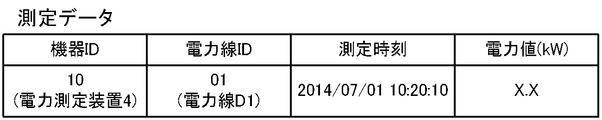
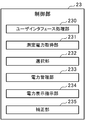
需要地における複数の電力線のそれぞれにおいて、1又は複数の機器により測定された電力値に関する測定データを各機器から取得し、記憶部に保存する測定電力取得手段と、
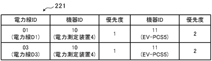
同一の電力線で測定された複数の電力値がある場合、当該電力線で測定された電力値として、前記複数の電力値から、予め各機器に付与されている優先度に基づいて一の電力値を選択する選択手段と、
各電力線で測定された電力値を用いて前記需要地で消費される電力の管理を行う電力管理手段と、
各電力線で測定された電力値を示す情報を予め定めた態様で表示装置に表示させる電力表示指示手段と、を備える。 In order to achieve the above object, an energy management controller according to the present invention provides:
In each of the plurality of power lines in the demand area, the measurement power acquisition means for acquiring the measurement data related to the power value measured by one or a plurality of devices from each device and storing it in the storage unit;
When there are a plurality of power values measured on the same power line, the power value measured on the power line is determined based on the priority given to each device in advance from the plurality of power values. A selection means to select;
Power management means for managing power consumed in the demand area using the power value measured in each power line;
Power display instruction means for displaying information indicating the power value measured on each power line on the display device in a predetermined manner.
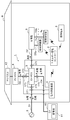
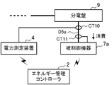
図1は、本発明の実施形態1に係るエネルギー管理システム1の全体構成を示す図である。このエネルギー管理システム1は、一般家庭で使用される電力の管理を行う、いわゆる、HEMS(Home Energy Management System)と呼ばれるシステムである。エネルギー管理システム1は、エネルギー管理コントローラ2と、操作端末3と、電力測定装置4と、EV-PCS5と、PV-PCS6と、複数の被制御機器7(被制御機器7a,7b,…)と、を備える。 (Embodiment 1)
FIG. 1 is a diagram showing an overall configuration of an
続いて、本発明の実施形態2について説明する。なお、以下の説明において、実施形態1と共通する構成要素等については、同一の符号を付し、その説明を省略する。 (Embodiment 2)
Subsequently,
Claims (9)
- 需要地における複数の電力線のそれぞれにおいて、1又は複数の機器により測定された電力値に関する測定データを各機器から取得し、記憶部に保存する測定電力取得手段と、
同一の電力線で測定された複数の電力値がある場合、当該電力線で測定された電力値として、前記複数の電力値から、予め各機器に付与されている優先度に基づいて一の電力値を選択する選択手段と、
各電力線で測定された電力値を用いて前記需要地で消費される電力の管理を行う電力管理手段と、
各電力線で測定された電力値を示す情報を予め定めた態様で表示装置に表示させる電力表示指示手段と、を備える、エネルギー管理コントローラ。 In each of the plurality of power lines in the demand area, the measurement power acquisition means for acquiring the measurement data related to the power value measured by one or a plurality of devices from each device and storing it in the storage unit;
When there are a plurality of power values measured on the same power line, the power value measured on the power line is determined based on the priority given to each device in advance from the plurality of power values. A selection means to select;
Power management means for managing power consumed in the demand area using the power value measured in each power line;
An energy management controller, comprising: power display instruction means for displaying information indicating a power value measured on each power line on a display device in a predetermined manner. - 前記優先度は、各機器の測定精度に基づいて決定され、最も測定精度が高い機器に対して最も高い優先度が付与されている、請求項1に記載のエネルギー管理コントローラ。 The energy management controller according to claim 1, wherein the priority is determined based on measurement accuracy of each device, and the highest priority is given to a device having the highest measurement accuracy.
- 前記優先度は、各機器における測定対象の電力線の数に基づいて決定され、最も測定対象の電力線の数が多い機器に対して最も高い優先度が付与されている、請求項1に記載のエネルギー管理コントローラ。 The energy according to claim 1, wherein the priority is determined based on the number of power lines to be measured in each device, and the highest priority is given to a device having the largest number of power lines to be measured. Management controller.
- 前記優先度は、各機器における電力測定のサンプリング間隔に基づいて決定され、最も前記サンプリング間隔が短い機器に対して最も高い優先度が付与されている、請求項1に記載のエネルギー管理コントローラ。 The energy management controller according to claim 1, wherein the priority is determined based on a sampling interval of power measurement in each device, and the highest priority is given to a device having the shortest sampling interval.
- 各電力線で測定された電力値の測定時刻のずれを補正する補正手段をさらに備える、請求項1から4の何れか1項に記載のエネルギー管理コントローラ。 The energy management controller according to any one of claims 1 to 4, further comprising correction means for correcting a shift in measurement time of the power value measured on each power line.
- 前記補正手段は、前記記憶部から予め定めた期間分の測定データを読み出し、読み出した各測定データから電力の立ち上がり時刻を検出し、検出した時刻を異なる電力線における測定データ同士で比較することで前記測定時刻のずれを補正する、請求項5に記載のエネルギー管理コントローラ。 The correction means reads the measurement data for a predetermined period from the storage unit, detects the power rise time from each read measurement data, and compares the detected time between the measurement data in different power lines. The energy management controller according to claim 5, wherein a deviation in measurement time is corrected.
- 前記補正手段は、前記記憶部から予め定めた期間分の測定データを読み出し、読み出した電力線毎の複数の測定データに対して、予め定めた時間間隔での平均化処理を施すことで前記測定時刻のずれを補正する、請求項5に記載のエネルギー管理コントローラ。 The correction means reads the measurement data for a predetermined period from the storage unit, and performs the averaging process at a predetermined time interval on the plurality of measurement data for each read power line, thereby measuring the measurement time. The energy management controller according to claim 5, wherein the deviation is corrected.
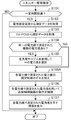
- 測定電力取得手段が、需要地における複数の電力線のそれぞれにおいて、1又は複数の機器により測定された電力値に関する測定データを各機器から取得し、
選択手段が、同一の電力線で測定された複数の電力値がある場合、当該電力線で測定された電力値として、前記複数の電力値から、予め各機器に付与されている優先度に基づいて一の電力値を選択し、
電力管理手段が、各電力線で測定された電力値を用いて前記需要地で消費される電力の管理を行い、
電力表示指示手段が、各電力線で測定された電力値を示す情報を予め定めた態様で表示装置に表示させる、エネルギー管理方法。 The measurement power acquisition means acquires measurement data related to the power value measured by one or more devices in each of the plurality of power lines in the demand area from each device,
When the selection unit has a plurality of power values measured on the same power line, the power value measured on the power line is determined based on the priority given to each device in advance from the plurality of power values. Select the power value for
The power management means manages the power consumed in the demand area using the power value measured on each power line,
An energy management method in which the power display instruction means causes the display device to display information indicating the power value measured on each power line in a predetermined manner. - コンピュータを、
需要地における複数の電力線のそれぞれにおいて、1又は複数の機器により測定された電力値に関する測定データを各機器から取得し、記憶部に保存する測定電力取得手段、
同一の電力線で測定された複数の電力値がある場合、当該電力線で測定された電力値として、前記複数の電力値から、予め各機器に付与されている優先度に基づいて一の電力値を選択する選択手段、
各電力線で測定された電力値を用いて前記需要地で消費される電力の管理を行う電力管理手段、
各電力線で測定された電力値を示す情報を予め定めた態様で表示装置に表示させる電力表示指示手段、として機能させるためのプログラム。 Computer
In each of the plurality of power lines in the demand area, the measurement power acquisition means for acquiring the measurement data related to the power value measured by one or a plurality of devices from each device and storing it in the storage unit,
When there are a plurality of power values measured on the same power line, the power value measured on the power line is determined based on the priority given to each device in advance from the plurality of power values. Selection means to select,
A power management means for managing power consumed in the demand area using a power value measured in each power line;
A program for functioning as power display instruction means for displaying information indicating a power value measured on each power line on a display device in a predetermined manner.
Priority Applications (5)
| Application Number | Priority Date | Filing Date | Title |
|---|---|---|---|
| EP14898422.2A EP3176907B1 (en) | 2014-07-28 | 2014-07-28 | Energy management controller, energy management method, and program |
| PCT/JP2014/069844 WO2016016931A1 (en) | 2014-07-28 | 2014-07-28 | Energy management controller, energy management method, and program |
| US15/127,129 US10424932B2 (en) | 2014-07-28 | 2014-07-28 | Energy management controller, energy management method, and program |
| CN201480079395.7A CN106464007B (en) | 2014-07-28 | 2014-07-28 | Energy management controller and energy management method |
| JP2016537624A JP6161822B2 (en) | 2014-07-28 | 2014-07-28 | Energy management controller, energy management method and program |
Applications Claiming Priority (1)
| Application Number | Priority Date | Filing Date | Title |
|---|---|---|---|
| PCT/JP2014/069844 WO2016016931A1 (en) | 2014-07-28 | 2014-07-28 | Energy management controller, energy management method, and program |
Publications (1)
| Publication Number | Publication Date |
|---|---|
| WO2016016931A1 true WO2016016931A1 (en) | 2016-02-04 |
Family
ID=55216877
Family Applications (1)
| Application Number | Title | Priority Date | Filing Date |
|---|---|---|---|
| PCT/JP2014/069844 WO2016016931A1 (en) | 2014-07-28 | 2014-07-28 | Energy management controller, energy management method, and program |
Country Status (5)
| Country | Link |
|---|---|
| US (1) | US10424932B2 (en) |
| EP (1) | EP3176907B1 (en) |
| JP (1) | JP6161822B2 (en) |
| CN (1) | CN106464007B (en) |
| WO (1) | WO2016016931A1 (en) |
Cited By (7)
| Publication number | Priority date | Publication date | Assignee | Title |
|---|---|---|---|---|
| JP2017102087A (en) * | 2015-12-04 | 2017-06-08 | 東芝ライテック株式会社 | Measurement management system |
| WO2017130327A1 (en) * | 2016-01-27 | 2017-08-03 | 三菱電機株式会社 | Energy management device, electric power information display method, and program |
| WO2017183232A1 (en) * | 2016-04-19 | 2017-10-26 | 日本電気株式会社 | Control device, control system, control method, and program |
| JPWO2017130326A1 (en) * | 2016-01-27 | 2018-04-26 | 三菱電機株式会社 | Energy management apparatus, power information display method and program |
| JP2018182853A (en) * | 2017-04-07 | 2018-11-15 | 河村電器産業株式会社 | Power monitoring device |
| JP2021125939A (en) * | 2020-02-04 | 2021-08-30 | トヨタ自動車株式会社 | Electric energy measurement system, electric energy measurement method, and electric energy measurement device |
| WO2024069851A1 (en) * | 2022-09-29 | 2024-04-04 | 住友電気工業株式会社 | Measurement accuracy management system, management device, management method, management program, and charging/discharging device |
Families Citing this family (2)
| Publication number | Priority date | Publication date | Assignee | Title |
|---|---|---|---|---|
| US10671946B2 (en) * | 2016-02-28 | 2020-06-02 | Quabbin Patent Holdings, Inc. | Multinodal power sensing, aggregation, and transmission |
| US11411429B2 (en) * | 2016-03-29 | 2022-08-09 | Kyocera Corporation | Management system, management method, power conversion device, and management device |
Citations (3)
| Publication number | Priority date | Publication date | Assignee | Title |
|---|---|---|---|---|
| JP2011004544A (en) * | 2009-06-19 | 2011-01-06 | Panasonic Electric Works Denro Co Ltd | Power monitoring system |
| JP2011244621A (en) * | 2010-05-19 | 2011-12-01 | Toshiba Corp | Accident analyzer for electric power system |
| JP2014039362A (en) * | 2012-08-13 | 2014-02-27 | Kyocera Corp | Energy management device, energy management method, and energy management system |
Family Cites Families (10)
| Publication number | Priority date | Publication date | Assignee | Title |
|---|---|---|---|---|
| JP2001109781A (en) * | 1999-10-13 | 2001-04-20 | Toshiba Corp | System for collecting data |
| JP2004020284A (en) * | 2002-06-13 | 2004-01-22 | Mitsubishi Electric Corp | Device for orienting accident point |
| JP4649397B2 (en) * | 2006-12-01 | 2011-03-09 | 中国電力株式会社 | Waveform recording apparatus and waveform recording method |
| JP2012145466A (en) * | 2011-01-13 | 2012-08-02 | Sharp Corp | Current measurement system and power measurement system |
| WO2013069671A1 (en) * | 2011-11-11 | 2013-05-16 | シャープ株式会社 | Power management device, control method and control program for power management device |
| US8417391B1 (en) * | 2011-12-15 | 2013-04-09 | Restore Nv | Automated demand response energy management system |
| JP6179048B2 (en) | 2012-03-30 | 2017-08-16 | パナソニックIpマネジメント株式会社 | Power measuring device |
| JP5814979B2 (en) * | 2013-06-13 | 2015-11-17 | 三菱電機株式会社 | Power measurement apparatus, determination method, and program |
| JP6126499B2 (en) * | 2013-08-30 | 2017-05-10 | 株式会社東芝 | Power conversion apparatus, cooperative control method, and program |
| WO2015159388A1 (en) * | 2014-04-16 | 2015-10-22 | 三菱電機株式会社 | Control apparatus, control system, control method, and program |
-
2014
- 2014-07-28 JP JP2016537624A patent/JP6161822B2/en active Active
- 2014-07-28 CN CN201480079395.7A patent/CN106464007B/en active Active
- 2014-07-28 EP EP14898422.2A patent/EP3176907B1/en active Active
- 2014-07-28 US US15/127,129 patent/US10424932B2/en active Active
- 2014-07-28 WO PCT/JP2014/069844 patent/WO2016016931A1/en active Application Filing
Patent Citations (3)
| Publication number | Priority date | Publication date | Assignee | Title |
|---|---|---|---|---|
| JP2011004544A (en) * | 2009-06-19 | 2011-01-06 | Panasonic Electric Works Denro Co Ltd | Power monitoring system |
| JP2011244621A (en) * | 2010-05-19 | 2011-12-01 | Toshiba Corp | Accident analyzer for electric power system |
| JP2014039362A (en) * | 2012-08-13 | 2014-02-27 | Kyocera Corp | Energy management device, energy management method, and energy management system |
Cited By (9)
| Publication number | Priority date | Publication date | Assignee | Title |
|---|---|---|---|---|
| JP2017102087A (en) * | 2015-12-04 | 2017-06-08 | 東芝ライテック株式会社 | Measurement management system |
| WO2017130327A1 (en) * | 2016-01-27 | 2017-08-03 | 三菱電機株式会社 | Energy management device, electric power information display method, and program |
| JPWO2017130327A1 (en) * | 2016-01-27 | 2018-04-12 | 三菱電機株式会社 | Energy management apparatus, power information display method and program |
| JPWO2017130326A1 (en) * | 2016-01-27 | 2018-04-26 | 三菱電機株式会社 | Energy management apparatus, power information display method and program |
| WO2017183232A1 (en) * | 2016-04-19 | 2017-10-26 | 日本電気株式会社 | Control device, control system, control method, and program |
| JP2018182853A (en) * | 2017-04-07 | 2018-11-15 | 河村電器産業株式会社 | Power monitoring device |
| JP2021125939A (en) * | 2020-02-04 | 2021-08-30 | トヨタ自動車株式会社 | Electric energy measurement system, electric energy measurement method, and electric energy measurement device |
| JP7294172B2 (en) | 2020-02-04 | 2023-06-20 | トヨタ自動車株式会社 | Electric energy measuring system, electric energy measuring method, and electric energy measuring device |
| WO2024069851A1 (en) * | 2022-09-29 | 2024-04-04 | 住友電気工業株式会社 | Measurement accuracy management system, management device, management method, management program, and charging/discharging device |
Also Published As
| Publication number | Publication date |
|---|---|
| US10424932B2 (en) | 2019-09-24 |
| CN106464007A (en) | 2017-02-22 |
| US20170207632A1 (en) | 2017-07-20 |
| CN106464007B (en) | 2019-10-11 |
| JP6161822B2 (en) | 2017-07-12 |
| JPWO2016016931A1 (en) | 2017-04-27 |
| EP3176907A4 (en) | 2018-01-24 |
| EP3176907A1 (en) | 2017-06-07 |
| EP3176907B1 (en) | 2019-10-02 |
Similar Documents
| Publication | Publication Date | Title |
|---|---|---|
| JP6161822B2 (en) | Energy management controller, energy management method and program | |
| JP6261721B2 (en) | Energy management system | |
| US10886755B2 (en) | Power control system, method, and power control apparatus | |
| US9893533B2 (en) | Server apparatus, electrical power control apparatus, and electrical power control system | |
| JP6198970B2 (en) | Control device, device control system, device control method and program | |
| JP6250077B2 (en) | Determination device, determination system, determination method, and program | |
| WO2017009909A1 (en) | Control device, control system, control method, and program | |
| JP6289502B2 (en) | Energy management system, system controller, and energy management method | |
| WO2016088289A1 (en) | Controlling device and controlling method | |
| US10291033B2 (en) | Power storage management system, power storage apparatus and power storage management method | |
| JP6373513B2 (en) | Control device, charging information display method and program | |
| US20160241033A1 (en) | Control device, control method, and program | |
| JP6385599B2 (en) | Energy management apparatus, power information display method and program | |
| JP6261755B2 (en) | Control device, device control method, and program | |
| WO2015159431A1 (en) | Energy management system, controller, energy management method and program | |
| JP6440873B2 (en) | Energy management apparatus, power information display method and program | |
| WO2017134788A1 (en) | Power consumption prediction device, power consumption prediction system, power consumption prediction method, and program | |
| WO2016084234A1 (en) | Communication device, communication adaptor, communication system, communication parameter response method, and program | |
| JP6698365B2 (en) | Power adjustment system, electric device, communication adapter, power adjustment method and program | |
| JP2018027010A (en) | Power measurement device, suppression level notification method, and program | |
| JP6173600B2 (en) | Electrical device, energy management system, consumable power acquisition method and program | |
| JP6746012B2 (en) | Control device, control system, control method, and program | |
| JPWO2018069958A1 (en) | Control device, power management system, power management method and program | |
| WO2016147411A1 (en) | Control device, control method, and program |
Legal Events
| Date | Code | Title | Description |
|---|---|---|---|
| 121 | Ep: the epo has been informed by wipo that ep was designated in this application |
Ref document number: 14898422 Country of ref document: EP Kind code of ref document: A1 |
|
| ENP | Entry into the national phase |
Ref document number: 2016537624 Country of ref document: JP Kind code of ref document: A |
|
| WWE | Wipo information: entry into national phase |
Ref document number: 15127129 Country of ref document: US |
|
| REEP | Request for entry into the european phase |
Ref document number: 2014898422 Country of ref document: EP |
|
| WWE | Wipo information: entry into national phase |
Ref document number: 2014898422 Country of ref document: EP |
|
| NENP | Non-entry into the national phase |
Ref country code: DE |