WO2017183232A1 - Control device, control system, control method, and program - Google Patents
Control device, control system, control method, and program Download PDFInfo
- Publication number
- WO2017183232A1 WO2017183232A1 PCT/JP2016/087378 JP2016087378W WO2017183232A1 WO 2017183232 A1 WO2017183232 A1 WO 2017183232A1 JP 2016087378 W JP2016087378 W JP 2016087378W WO 2017183232 A1 WO2017183232 A1 WO 2017183232A1
- Authority
- WO
- WIPO (PCT)
- Prior art keywords
- time
- series data
- clock
- control device
- control signal
- Prior art date
Links
Images


Classifications
-
- H—ELECTRICITY
- H02—GENERATION; CONVERSION OR DISTRIBUTION OF ELECTRIC POWER
- H02J—CIRCUIT ARRANGEMENTS OR SYSTEMS FOR SUPPLYING OR DISTRIBUTING ELECTRIC POWER; SYSTEMS FOR STORING ELECTRIC ENERGY
- H02J7/00—Circuit arrangements for charging or depolarising batteries or for supplying loads from batteries
- H02J7/00032—Circuit arrangements for charging or depolarising batteries or for supplying loads from batteries characterised by data exchange
-
- H—ELECTRICITY
- H02—GENERATION; CONVERSION OR DISTRIBUTION OF ELECTRIC POWER
- H02J—CIRCUIT ARRANGEMENTS OR SYSTEMS FOR SUPPLYING OR DISTRIBUTING ELECTRIC POWER; SYSTEMS FOR STORING ELECTRIC ENERGY
- H02J13/00—Circuit arrangements for providing remote indication of network conditions, e.g. an instantaneous record of the open or closed condition of each circuitbreaker in the network; Circuit arrangements for providing remote control of switching means in a power distribution network, e.g. switching in and out of current consumers by using a pulse code signal carried by the network
Definitions
- the present invention relates to a control device, a control system, a control method, and a program.
- Patent Document 1 discloses a technique for realizing time synchronization between a plurality of devices that perform power supply and demand adjustment based on a GPS (Global Positioning System) receiver included in each device.
- the power supply / demand adjustment is a process of maintaining the supply / demand balance of the power system. For example, in the case of excessive demand, the power supply from the power generation device or storage battery to the power system is increased. In the case of excessive supply, the power supply from the power generation device or storage battery to the power system is reduced, or the power is charged to the storage battery. To do.
- Time synchronization between devices that cooperate to execute a predetermined process is necessary to execute the process normally.
- An object of the present invention is to provide a new technique for realizing time synchronization between apparatuses.
- the first time-series data in which the time information at the time of measurement is associated with the measured value of the predetermined item of the power system, and the first time-series data used in the second device.
- First acquisition means for acquiring second time-series data in which time information at the time of measurement is associated with a measurement value of the predetermined item of the power system, based on a clock of 2;
- a time lag calculating means for calculating a time lag between the first clock and the second clock based on the first time series data and the second time series data;
- a control device is provided.
- Third time series data indicating the content of the control signal and the transmission time from the first device attached based on the first clock used in the first device, and the operation based on the control signal Second acquisition means for acquiring fourth time-series data indicating an operation content of the second device and an operation time attached based on a second clock used in the second device; Response time calculation means for calculating a response time from a transmission time of the control signal to an operation time at which an operation corresponding to the control signal is performed based on the third time series data and the fourth time series data
- a control device is provided.
- a first device that transmits a control signal to a second device; and the second device that operates based on the control signal;
- the first device includes: Means for transmitting, to the second device, first time-series data in which time information at the time of measurement is associated with a measured value of a predetermined item of the power system based on a first clock used in the first device.
- the second device includes: Means for receiving the first time-series data; Means for acquiring second time-series data in which time information at the time of measurement is associated with measurement values of the predetermined item of the power system based on a second clock used in the second device; Means for calculating a time lag between the first clock and the second clock based on the first time-series data and the second time-series data; A control system is provided.
- a first device that transmits a control signal to a second device; and the second device that operates based on the control signal;
- the second device includes: Means for transmitting, to the first device, second time-series data in which time information at the time of measurement is associated with a measured value of a predetermined item of the electric power system based on a second clock used in the second device.
- the first device includes: Means for receiving the second time-series data; Means for acquiring first time-series data in which time information at the time of measurement is associated with a measurement value of the predetermined item of the power system based on a first clock used in the first device; Means for calculating a time lag between the first clock and the second clock based on the first time-series data and the second time-series data; A control system is provided.
- the first time-series data in which the time information at the time of measurement is associated with the measured value of the predetermined item of the power system, and the first time-series data used in the second device.
- First acquisition means for acquiring second time-series data in which time information at the time of measurement is associated with a measurement value of the predetermined item of the power system based on a clock of 2;
- a time lag calculating means for calculating a time lag between the first clock and the second clock based on the first time series data and the second time series data;
- Each unit included in the apparatus of the present embodiment is stored in a CPU (Central Processing Unit), a memory, a program loaded into the memory, a storage unit such as a hard disk storing the program (from the stage of shipping the apparatus in advance).
- a storage unit such as a hard disk storing the program (from the stage of shipping the apparatus in advance).
- storage media such as CDs (Compact Discs) and programs downloaded from servers on the Internet can also be stored.) Realized by any combination of hardware and software, centering on the network connection interface Is done. It will be understood by those skilled in the art that there are various modifications to the implementation method and apparatus.
- FIG. 1 is a block diagram illustrating the hardware configuration of the apparatus according to the present embodiment.
- the apparatus includes a processor 1A, a memory 2A, an input / output interface 3A, a peripheral circuit 4A, and a bus 5A.
- the peripheral circuit includes various modules.
- the bus 5A is a data transmission path through which the processor 1A, the memory 2A, the peripheral circuit 4A, and the input / output interface 3A transmit / receive data to / from each other.
- the processor 1A is an arithmetic processing device such as a CPU (Central Processing Unit) or a GPU (Graphics Processing Unit).
- the memory 2A is a memory such as a RAM (Random Access Memory) or a ROM (Read Only Memory).
- the input / output interface 3A includes an interface for acquiring information from an external device, an external server, an external sensor, and the like.
- the processor 1A issues a command to each module and performs a calculation based on the calculation result.
- the control system of the present embodiment includes a first device 10 and a second device 20.
- the first device 10 and the second device 20 cooperate to execute a predetermined process.
- the 1st apparatus 10 is a central control apparatus which transmits a storage battery control signal
- the 2nd apparatus 20 is a terminal side control apparatus which controls a storage battery based on a storage battery control signal, it is not limited to this.
- the first device 10 has a function of inputting / outputting data, a function of storing data, and a function of performing arithmetic processing.
- the second device 20 has a function of inputting / outputting data, a function of storing data, and a function of arithmetic processing.
- the first device 10 and the second device 20 are connected to each other via a communication line 30 and can transmit and receive information.
- the first device 10 acquires first time series data.
- the first time series data includes values of predetermined items (eg, frequency, current value, voltage value, power factor, etc.) of the power system (power line 40) continuously measured by the measurement sensor 60 every predetermined time. Time-series data).
- the first time series data is associated with time information at the time of measurement of each value based on the first clock used in the first device 10.
- the first device 10 may have a measurement sensor 60.
- the first device 10 may have a first timepiece.
- the second device 20 acquires second time series data.
- the second time-series data is a value of a predetermined item (eg, frequency, current value, voltage value, power factor, etc.) of the power system (power line 40) continuously measured by the measurement sensor 70 every predetermined time. Time-series data).
- the second time series data is associated with time information at the time of measurement of each value based on the second clock used in the second device 20.
- the second device 20 may have a measurement sensor 70.
- the second device 20 may include a second timepiece.
- the measurement position of the measurement sensor 60 and the measurement position of the measurement sensor 70 are substantially the same as the time changes of the values of the predetermined items of the power system (eg, frequency, current value, voltage value, power factor, values normalized by these). Satisfies the relationship of “same state at timing”. For example, in the case of Japan, the system frequency is different between West Japan and East Japan, but both the measurement sensor 60 and the measurement sensor 70 can use the same system frequency area as the measurement position. More preferably, the measurement sensor 60 and the measurement sensor 70 can be located in the same power company jurisdiction. More preferably, the measurement sensor 60 and the measurement sensor 70 can set the measurement position to a region of the same new power jurisdiction within the same power company jurisdiction, a section to receive power supply from the same distribution station, or the like.
- the measurement sensor 60 and the measurement sensor 70 can be located in the same power company jurisdiction. More preferably, the measurement sensor 60 and the measurement sensor 70 can set the measurement position to a region of the same new power jurisdiction within the same power company jurisdiction, a section to receive power
- the control device (not shown in FIG. 2) of the present embodiment includes a first timepiece used in the first device 10 and a second time series based on the first time-series data and the second time-series data. The time difference from the second clock used in the device 20 is calculated.
- the first device 10 or the second device 20 includes a control device.
- the configuration of the control device will be described in detail.
- FIG. 3 shows an example of a functional block diagram of the control device 100.
- the control device 100 includes a first acquisition unit 101 and a time shift calculation unit 102.
- the first acquisition unit 101 acquires first time series data and second time series data.
- the first time-series data is time-series data in which time information at the time of measurement is associated with measurement values of predetermined items of the power system based on a first clock used in the first device 10.
- the second time-series data is time-series data in which time information at the time of measurement is associated with measured values of predetermined items of the power system based on a second clock used in the second device 20.
- the first time series data and the second time series data are as described above.
- the first time series data and the second time series data are preferably time series data measured at the same time in the same sampling period.
- the time interval of one waveform is 0.02 seconds. Therefore, the sampling period of the first time-series data and the second time-series data is less than 0.02 seconds when the measurement target is current, voltage, and power factor, and is 0. 0 when the measurement target is the system frequency. It is preferably about 02 seconds. Similarly, in a region where the reference value of the system frequency is 60 Hz, the time interval of one waveform is about 0.017 seconds. Therefore, the sampling period of the first time-series data and the second time-series data is less than 0.017 seconds when the measurement target is current, voltage and power factor, and is 0. 0 when the measurement target is the system frequency. It is preferable that the time be around 017 seconds.
- FIG. 4 schematically shows an example of the first time series data.
- the first time series data is data in which measurement values of predetermined items are associated with times at the time of measurement of the respective measurement values.
- the time at the time of measurement is a value specified based on the first clock.
- FIG. 5 schematically shows an example of the second time-series data.
- the second time series data is also data in which the measurement values of the predetermined items are associated with the times at the time of measurement of the respective measurement values.
- the time at the time of measurement is a value specified based on the second clock.
- Examples of the measured value of the predetermined item of the power system include, but are not limited to, a frequency (system frequency), a current value, a voltage value, a power factor, a value obtained by standardizing these, and the like.
- the control device 100 When the first device 10 shown in FIG. 2 includes the control device 100, the control device 100 generates first time series data and receives the second time series data from the second device 20.
- the second device 20 may transmit measurement values measured at a cycle of several seconds to the first device 10 (the control device 100) at a cycle of several seconds.
- the second device 20 accumulates the measured values measured, for example, in a cycle of several seconds, collects the accumulated measured values, and, for example, the first device 10 (control device 100) in a cycle of several tens of minutes to several hours. May be sent to. This assumption is the same in all the following embodiments.
- the control device 100 generates second time-series data and receives the first time-series data from the first device 10.
- the first device 10 may transmit measurement values measured at a cycle of several seconds to the second device 20 (the control device 100) at a cycle of several seconds.
- the first device 10 accumulates measurement values measured, for example, in a cycle of several seconds, and collects the accumulated measurement values, for example, the second device 20 (control device 100) in a cycle of several tens of minutes to several hours. May be sent to. This assumption is the same in all the following embodiments.
- the time lag calculation unit 102 calculates the time lag between the first clock and the second clock based on the first time series data and the second time series data.
- the time lag calculation unit 102 calculates the time lag based on the similarity between the waveform of the first time series data and the waveform of the second time series data.
- time lag calculation unit 102 is based on the waveform similarity based on the predetermined time data in the first time series data and the waveform similarity based on the predetermined time data in the second time series data.
- the time lag can be calculated.
- the predetermined time is a design matter that can be determined within a range in which a rough tendency of the waveform (a trend component excluding noise) can be understood.
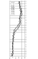
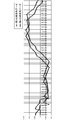
- FIG. 6 shows a diagram in which the first time series data and the second time series data are plotted on a graph.
- the horizontal axis is time, and the vertical axis is system frequency.
- the time shift calculation unit 102 calculates the similarity between two waveforms while shifting (moving) one waveform on the time axis.
- the shifting time is a value obtained by multiplying the sampling period of the first time series data and the second time series data by an integer. Then, the time shift calculation unit 102 calculates the shifted time t when the similarity is equal to or higher than a predetermined level as the time shift between the first clock and the second clock.
- the time lag calculation unit 102 may calculate the correlation coefficient of the first time series data and the second time series data as the similarity. In this case, the time shift calculation unit 102 calculates the shifted time t when the correlation coefficient is equal to or greater than a predetermined value as the time shift between the first clock and the second clock.
- the time-series data of the difference obtained by subtracting the other time-series data from one time-series data (the data obtained by arranging the difference obtained by subtracting the other value from one value in time series for each corresponding timing)
- the similarity may be calculated.
- the time lag calculation unit 102 calculates the shifted time t when a statistical value (eg, maximum value, average value) of a plurality of values included in the time series data of the difference is equal to or less than a predetermined value, You may calculate as a time gap between the 1st timepiece and the 2nd timepiece.
- the time shift calculation unit 102 may calculate the similarity corresponding to each while gradually increasing or decreasing the shift time tn and compare the similarity with a predetermined value. In this case, the number of times of similarity calculation and comparison tends to increase.
- the time lag calculation unit 102 may employ the following algorithm.
- the time lag calculation unit 102 calculates the degree of similarity corresponding to each representative member (eg, t3 and t8) of each group. If any one of the calculated similarities is equal to or greater than a predetermined value, the time shift calculation unit 102 sets the shifted time as the time shift.
- the time lag calculation unit 102 identifies the group with the higher similarity. Then, the degree of similarity is calculated for each member belonging to the specified group and compared with a predetermined value. The degree of similarity of each member of the specified group may be calculated, or the members of the specified group may be grouped in the same manner as described above and the same processing may be performed. According to this method, the number of similarity calculations and comparisons can be reduced.
- first device 10 and the second device 20 may be one-to-one or may be one-to-multiple. This assumption is the same in all the following embodiments.
- the first acquisition unit 101 associates time information at the time of measurement with measurement values of predetermined items of the power system based on the first timepiece used in the first device 10. Based on the time-series data and the plurality of second clocks used in each of the plurality of second devices 20, a plurality of second times in which time information at the time of measurement is associated with measured values of predetermined items of the power system. And time-series data. Then, the time lag calculation unit 102 calculates a time lag between the first clock and each of the plurality of second clocks based on the first time series data and each of the plurality of second time series data. calculate.
- the first device 10 may be provided with a GPS receiver, and may have a function of correcting the time of the first clock based on the GPS signal.
- the time difference between the one or more second timepieces can be accurately calculated. This assumption is the same in all the following embodiments.
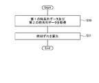
- the first acquisition unit 101 is based on a first clock used in the first device 10, and first time-series data in which time information at the time of measurement is associated with measurement values of predetermined items of the power system. And based on the 2nd timepiece used with the 2nd apparatus 20, the 2nd time series data which matched time information at the time of measurement with the measured value of the predetermined item of an electric power system is acquired (S10). .
- the time lag calculation unit 102 calculates the time lag between the first clock and the second clock based on the first time series data and the second time series data.
- a new technique for calculating the time lag between devices is realized.
- time synchronization between the devices is realized.
- a new time synchronization technique is realized.
- each device it is not necessary for each device to include an expensive device such as a GPS receiver. For this reason, the time synchronization realization method of this embodiment is excellent in cost.
- the time lag can be calculated based on the similarity between the waveform of the first time series data and the waveform of the second time series data.
- the measured value of the predetermined item of the power system may be the same value continuously. For this reason, when the similarity between the first time-series data and the second time-series data is calculated using only measured values at a certain time point, and a time lag is calculated, there is a possibility of calculating an incorrect time lag.
- the time lag calculation accuracy can be increased.
- a third device that is physically and / or logically separated from the first device 10 and the second device 20 may include the control device 100.
- the third device receives the first time-series data and the second time-series data from the first device 10 and the second device 20, and based on them, the first timepiece and the second timepiece The time difference between them is calculated.
- the control device 100 has a function of correcting the first time series data and the second time series data. For example, when the sampling period of the first time-series data and the second time-series data is larger than the minimum value of the time shift to be detected, a desired time shift cannot be detected.
- the control device 100 corrects the sampling period by interpolating the data into the first time series data and the second time series data so that a desired time lag can be detected. This will be described below.
- FIG. 8 shows an example of a functional block diagram of the control device 100 of the present embodiment.
- the control device 100 includes a first acquisition unit 101, a time shift calculation unit 102, and a correction unit 103.
- the configurations of the first acquisition unit 101 and the time shift calculation unit 102 are the same as those in the first embodiment.
- the correction unit 103 interpolates data into the first time series data and the second time series data.
- the first acquisition unit 101 inputs the first time series data and the second time series data to the correction unit 103.
- the correction unit 103 determines whether interpolation is necessary based on a reference value of a sampling period that is held in advance.
- the correction unit 103 determines that the interpolation for the first time-series data and the second time-series data is unnecessary when the “sampling period is equal to or less than the reference value”. Then, the correction unit 103 inputs the first time series data and the second time series data to the time shift calculation unit 102 as they are.
- the correction unit 103 determines that interpolation for the first time series data and the second time series data is necessary. Then, the correction unit 103 performs an interpolation process on the first time-series data and the second time-series data, and then converts the first time-series data and the second time-series data after the interpolation process to a time Input to the deviation calculation unit 102.
- the correction unit 103 can employ any technique to interpolate data. For example, spline interpolation is exemplified. For example, the correcting unit 103 may estimate the data value between the preceding and subsequent data values and interpolate the estimated value.
- the time lag calculation unit 102 calculates the time lag between the first clock and the second clock based on the data input from the correction unit 103.
- the same operational effects as those of the first embodiment can be realized. Further, according to the present embodiment, by interpolating data into the first time-series data and the second time-series data, it becomes possible to increase the resolution of the detectable time lag and calculate the desired time lag. .
- the control system of the present embodiment further has a function of correcting the second clock based on the calculated time lag and synchronizing the first clock and the second clock. This will be described below. In the present embodiment, it is assumed that the first device 10 shown in FIG.
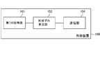
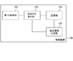
- FIG. 9 shows an example of a functional block diagram of the control device 100 of the present embodiment.
- the control device 100 includes a first acquisition unit 101, a time shift calculation unit 102, and a transmission unit 104.
- the control device 100 may further include a correction unit 103.
- the configurations of the first acquisition unit 101, the time shift calculation unit 102, and the correction unit 103 are the same as those in the first and second embodiments.
- the transmission unit 104 transmits to the second device 20 a correction instruction for correcting the second clock based on the calculated time difference.
- the correction instruction includes the contents of the time lag (the progress time or the delay time).
- the second device 20 that has received the correction instruction corrects the second clock according to the correction instruction, and eliminates the time lag with respect to the first clock.
- the same operational effects as those of the first and second embodiments can be realized. Further, according to the present embodiment, the first clock and the second clock can be synchronized by correcting the second clock.
- the control system of the present embodiment further has a function of correcting the second clock based on the calculated time lag and synchronizing the first clock and the second clock. This will be described below. In the present embodiment, it is assumed that the second device 20 shown in FIG.
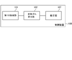
- FIG. 10 shows an example of a functional block diagram of the control device 100 of the present embodiment.
- the control device 100 includes a first acquisition unit 101, a time lag calculation unit 102, and a correction unit 107.
- the control device 100 may further include a correction unit 103.
- the configurations of the first acquisition unit 101, the time shift calculation unit 102, and the correction unit 103 are the same as those in the first to third embodiments.
- the correction unit 107 corrects the second clock based on the calculated time lag, and eliminates the time lag with the first clock.
- the same operational effects as those of the first and second embodiments can be realized. Further, according to the present embodiment, the first clock and the second clock can be synchronized by correcting the second clock.
- the control system according to the present embodiment further has a function of generating estimation information for calculating the time shift from the elapsed time based on the past performance indicating the elapsed time and the time shift generated during that time. This will be described below.
- the first device 10 shown in FIG. it is assumed that the first device 10 shown in FIG. That is, the first device 10 generates estimation information. Then, the first device 10 calculates a time lag based on the estimated information and the elapsed time.
- FIG. 11 shows an example of a functional block diagram of the control device 100 of the present embodiment.
- the control device 100 includes a first acquisition unit 101, a time shift calculation unit 102, a transmission unit 104, and an estimated information generation unit 105.
- the control device 100 may further include a correction unit 103.
- the configurations of the first acquisition unit 101, the time shift calculation unit 102, the correction unit 103, and the transmission unit 104 are the same as those in the first to fourth embodiments.
- the estimated information generation unit 105 generates estimated information for calculating the time lag from the elapsed time based on the elapsed time and the past results indicating the time lag generated during the elapsed time.
- the time lag calculation unit 102 repeatedly calculates the time lag between the first clock and the second clock at a predetermined cycle (a cycle of several tens of minutes to several hours). Then, the transmission unit 104 transmits a correction instruction based on the calculated time lag to the second device 20 each time.
- the elapsed time is an elapsed time from the nth process to the (n + 1) th process.
- the time lag occurring during the elapsed time is the time lag calculated in the (n + 1) th process.
- the timing at which the correction instruction is transmitted to the second device 20 in the n-th process may be set as the starting point of the elapsed time.
- the first device 10 may receive a completion notification indicating that the correction of the second clock has been completed from the second device 20.
- the 1st apparatus 10 is good also considering the said reception timing as the starting point of elapsed time.
- the timing at which the time lag is calculated in the (n + 1) th process may be the end point of the elapsed time.
- Such past results are stored in the control device 100 or in an external device configured to be able to communicate with the control device 100.
- the relationship between the first device 10 and the second device 20 is one-to-multiple, past results are accumulated in association with each of the plurality of second devices 20.
- the estimation information generation unit 105 generates estimation information (eg, estimation formula) for calculating a time lag from the elapsed time based on such past results.
- estimation information eg, estimation formula
- the generation method of the estimation information is a design matter, and for example, a method such as regression analysis can be adopted.
- the time lag calculating unit 102 can calculate the time lag between the first clock and the second clock based on the estimated information and the elapsed time after the estimated information is generated.
- the same operational effects as those of the first to fourth embodiments can be realized. Further, according to the present embodiment, it is possible to calculate the time difference between the first clock and the second clock based on the elapsed time and the estimated information. After the estimation information is generated, the calculation method based on the first time series data and the second time series data is replaced with a calculation method based on the elapsed time and the estimation information, so that the calculation burden on the computer can be reduced.
- the relationship between the first device 10 and the second device 20 is one-to-multiple.
- the control system of the present embodiment groups a plurality of second clocks used in each of the plurality of second devices 20 based on the past results described in the fifth embodiment. And it has further the function which produces
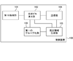
- FIG. 12 shows an example of a functional block diagram of the control device 100 of the present embodiment.
- the control device 100 includes a first acquisition unit 101, a time lag calculation unit 102, a transmission unit 104, an estimated information generation unit 105, and a first grouping unit 106.
- the control device 100 may further include a correction unit 103.
- the configurations of the first acquisition unit 101, the time shift calculation unit 102, the correction unit 103, and the transmission unit 104 are the same as those in the first to fifth embodiments.
- the first grouping unit 106 groups a plurality of second clocks used in each of the plurality of second devices 20 based on past results.
- the past performance is data indicating the elapsed time and the time lag generated between the elapsed times.
- the first grouping unit 106 creates a group of second clocks having similar time shift trends.
- the grouping method is a design matter.
- the time lag at the elapsed time m may be divided into a group having a predetermined value or more and a group having a predetermined value or less.
- the number of groups is not limited to two and may be more than that.
- the estimation information generation unit 105 generates estimation information common to each group for each group. That is, the estimated information generation unit 105 does not generate estimated information for each second clock, but generates estimated information for each group.
- the estimation information generation unit 105 estimates, for each group, estimation information that calculates a time lag from the elapsed time based on all or part of past results of a plurality of members (second clocks) of each group (example: estimation) Expression).
- the generation method of the estimation information is a design matter, and for example, a method such as regression analysis can be adopted.
- the time lag calculating unit 102 can calculate the time lag between the first clock and the second clock based on the estimated information and the elapsed time after the estimated information is generated.
- the time lag calculation unit 102 calculates the time lag of each of the second clocks based on the estimation information generated corresponding to the group to which each of the second clocks belongs.
- the same operational effects as those of the first to fifth embodiments can be realized.
- the control system of the present embodiment further has a function of generating estimation information for calculating a time shift from the elapsed time based on past results indicating the elapsed time and the time shift therebetween. This will be described below.
- the second device 20 shown in FIG. it is assumed that the second device 20 shown in FIG. That is, the second device 20 generates estimation information. Then, the second device 20 calculates a time lag based on the estimated information and the elapsed time.
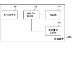
- FIG. 13 shows an example of a functional block diagram of the control device 100 of the present embodiment.
- the control device 100 includes a first acquisition unit 101, a time lag calculation unit 102, an estimated information generation unit 105, and a correction unit 107.
- the control device 100 may further include a correction unit 103.
- the configurations of the first acquisition unit 101, the time shift calculation unit 102, the correction unit 103, and the correction unit 107 are the same as those in the first to sixth embodiments.
- the estimated information generation unit 105 generates estimated information for calculating the time lag from the elapsed time based on the elapsed time and the past results indicating the time lag generated during the elapsed time.
- the time lag calculation unit 102 repeatedly calculates the time lag between the first clock and the second clock at a predetermined cycle (a cycle of several tens of minutes to several hours). Then, the correction unit 107 corrects the second timepiece based on the calculated time difference each time.
- the elapsed time is an elapsed time from the nth process to the (n + 1) th process.
- the time lag occurring during the elapsed time is the time lag calculated in the (n + 1) th process.
- the timing at which the second clock is corrected in the n-th process may be set as the starting point of the elapsed time.
- the timing at which the time lag is calculated in the (n + 1) th process may be the end point of the elapsed time.
- Such past results are stored in the control device 100 or in an external device configured to be able to communicate with the control device 100.
- each control device 100 included in each second device 20 or an external device configured to be able to communicate with each control device 100 Each past performance is accumulated in the inside.
- the estimation information generation unit 105 generates estimation information (eg, estimation formula) for calculating a time lag from the elapsed time based on such past results.
- estimation information eg, estimation formula
- the generation method of the estimation information is a design matter, and for example, a method such as regression analysis can be adopted.
- the time lag calculating unit 102 can calculate the time lag between the first clock and the second clock based on the estimated information and the elapsed time after the estimated information is generated.
- the same operational effects as those of the first to fourth embodiments can be realized. Further, according to the present embodiment, it is possible to calculate the time difference between the first clock and the second clock based on the elapsed time and the estimated information. After the estimation information is generated, the calculation method based on the first time series data and the second time series data is replaced with a calculation method based on the elapsed time and the estimation information, so that the calculation burden on the computer can be reduced.
- the first device 10 shown in FIG. 2 transmits a control signal to the second device 20.
- the second device 20 operates based on the control signal.
- the control device 100 further has a function of calculating a response time from the transmission of the control signal by the first device 10 until the operation according to the control signal by the second device 20 is performed. This will be described below.
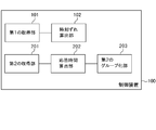
- FIG. 14 shows an example of a functional block diagram of the control device 100 of the present embodiment.
- the control device 100 includes a first acquisition unit 101, a time lag calculation unit 102, a second acquisition unit 201, and a response time calculation unit 202.
- the control apparatus 100 further includes one or more of a correction unit 103, a transmission unit 104, an estimation information generation unit 105, a first grouping unit 106, and a correction unit 107. Also good.
- the configurations of the first acquisition unit 101, time shift calculation unit 102, correction unit 103, transmission unit 104, estimation information generation unit 105, first grouping unit 106, and correction unit 107 are the first to seventh embodiments. It is the same.
- the second acquisition unit 201 acquires the third time series data and the fourth time series data.
- the third time series data indicates the content of the control signal transmitted from the first device 10 to the second device 20 and the transmission time from the first device 10 attached based on the first clock.
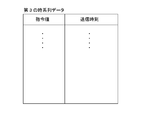
- the fourth time-series data indicates the operation content of the second device 20 and the operation time assigned based on the second clock.
- the first device 10 is a central control device that transmits a storage battery control signal (control signal) and the second device 20 is a terminal-side control device that controls the storage battery based on the storage battery control signal (control signal), the storage battery
- the content of the control signal (control signal) is, for example, a command value for the output power [W] or the charging power [W] of the storage battery.
- the operation content of the second device 20 is a measured value (response value) of the output power [W] or the charging power [W] of the storage battery operated under the control of the second device 20.
- FIGS. 15 and 16 schematically show examples of such third time-series data and fourth time-series data.
- the content of the storage battery control signal may be a value for calculating a command value for the output power [W] or the charging power [W] of the storage battery. For example, information for specifying the burden ratio is given to each of the plurality of second devices 20 in advance. Then, as the storage battery control signal (control signal), the value of the output power [W] or the charging power [W] of the entire plurality of storage batteries is transmitted to each second device 20.
- the contents transmitted to the plurality of second devices 20 are the same contents, they may be transmitted simultaneously by broadcast or the like.
- Each second device 20 calculates its own share of the output power [W] or charging power [W] of the plurality of storage batteries as a command value.
- control signal The premise regarding the contents of the storage battery control signal (control signal) is the same in all of the following embodiments. Even in such a case, it is possible to realize the same effect as the case where the content of the storage battery control signal (control signal) is a command value.
- the first device 10 generates third time series data
- the second device 20 generates fourth time series data.
- the control device 100 When the first device 10 shown in FIG. 2 includes the control device 100, the control device 100 generates third time series data and receives the fourth time series data from the second device 20.
- the second device 20 may transmit a response value measured at a cycle of several seconds to the first device 10 (the control device 100) at a cycle of several seconds.
- the second device 20 accumulates response values measured, for example, in a cycle of several seconds, and collects the accumulated response values, for example, the first device 10 (control device 100) in a cycle of several tens of minutes to several hours, for example. May be sent to. This assumption is the same in all the following embodiments.
- the control device 100 When the second device 20 includes the control device 100, the control device 100 generates fourth time-series data and receives the third time-series data from the first device 10.
- the response time calculation unit 202 calculates the response time from the transmission time of the control signal to the operation time when the operation corresponding to the control signal is performed based on the third time series data and the fourth time series data. .
- the response time calculation unit 202 calculates a response time based on the similarity between the waveform of the third time series data and the waveform of the fourth time series data.
- the response time calculation unit 202 is based on a waveform based on data for a predetermined time in the third time-series data and a waveform similarity based on the data for the predetermined time in the fourth time-series data.
- the time lag can be calculated.
- the predetermined time is a design matter that can be determined within a range in which a rough tendency of the waveform (a trend component excluding noise) can be understood.
- FIG. 17 shows a diagram in which the third time-series data and the fourth time-series data are plotted on a graph.
- the horizontal axis is time
- the vertical axis is a value obtained by standardizing command values and response values under predetermined conditions.
- the response time calculation unit 202 calculates the similarity between two waveforms while shifting one waveform on the time axis (moving).
- the shifting time is a value obtained by multiplying the sampling period of the third time series data and the fourth time series data by an integer. Then, the response time calculation unit 202 calculates the shifted time t ′ when the similarity is equal to or higher than a predetermined level as the response time.
- the response time calculation unit 202 may calculate the correlation coefficient of the third time series data and the fourth time series data as the similarity. In this case, the response time calculation unit 202 calculates the shifted time t ′ when the correlation coefficient is equal to or greater than a predetermined value as the response time.
- the time-series data of the difference obtained by subtracting the other time-series data from one time-series data (the data obtained by arranging the difference obtained by subtracting the other value from one value in time series for each corresponding timing)
- the similarity may be calculated.
- the response time calculation unit 202 calculates a shifted time t ′ when a statistical value (eg, maximum value, average value) of a plurality of values included in the time series data of the difference is equal to or less than a predetermined value.
- the response time may be calculated.
- the second acquisition unit 201 uses third time-series data based on the first clock used in the first device 10. And a plurality of fourth time series data based on each of the plurality of second clocks used in each of the plurality of second devices 20. Then, the response time calculation unit 202 calculates a response time corresponding to each of the plurality of second devices 20 based on the third time series data and each of the plurality of fourth time series data.
- the same operational effects as those of the first to seventh embodiments can be realized. Further, according to the present embodiment, the response time from the transmission time at which the control signal is transmitted from the first device 10 to the operation time at which the operation by the second device 20 corresponding to the control signal is performed is calculated. be able to. With the method described in the first to seventh embodiments, time synchronization between the first clock used in the first device 10 and the second clock used in the second device 20 is performed. Thus, the response time can be calculated with high accuracy.
- the response time can be calculated based on the similarity between the waveform of the third time series data and the waveform of the fourth time series data.
- the command value and the response value may be the same value in succession. For this reason, when the similarity between the third time-series data and the fourth time-series data is calculated using only the command value and the response value at a certain point in time and the response time is calculated, there is a possibility of calculating an incorrect response time. is there. In the case of this embodiment in which the response time can be calculated based on the similarity between the waveform of the third time series data and the waveform of the fourth time series data, the calculation accuracy of the response time can be increased.
- the first device 10 transmits a control signal to the second device 20.
- the second device 20 operates based on the control signal.
- the control device 100 that calculates the time difference between the first timepiece and the second timepiece and the control device 200 that is physically and / or logically separated responds to the control signal from the transmission time of the control signal. The response time until the operation time at which the operation is performed is calculated.
- control device 100 that calculates the time difference between the first timepiece and the second timepiece” and “the operation in which the operation according to the control signal is performed from the transmission time of the control signal”
- the control device 200 for calculating the response time up to the time is physically and / or logically separated.
- FIG. 3 shows an example of a functional block diagram of the control device 100.
- the control device 100 includes a first acquisition unit 101 and a time shift calculation unit 102.
- the control device 100 may further include one or more of a correction unit 103, a transmission unit 104, an estimation information generation unit 105, a first grouping unit 106, and a correction unit 107.
- the configurations of the first acquisition unit 101, the time shift calculation unit 102, the correction unit 103, the transmission unit 104, the estimation information generation unit 105, the first grouping unit 106, and the correction unit 107 are the first to eighth embodiments. It is the same.
- FIG. 18 shows an example of a functional block diagram of the control device 200.
- the control device 200 includes a second acquisition unit 201 and a response time calculation unit 202.
- the configurations of the second acquisition unit 201 and the response time calculation unit 202 are the same as those in the eighth embodiment.
- one of the first device 10 and the second device 20 shown in FIG. 2 has the control device 100, and the other has the control device 200.
- the first device 10 may include the control device 100 and the second device 20 may include the control device 200.
- the second device 20 may include the control device 100, and the second device 20 may include the control device 100.
- the same functions and effects as those of the first to eighth embodiments can be realized. Further, the calculation of the time lag and the calculation of the response time can be divided into the first device 10 and the second device 20. For this reason, the inconvenience that the processing load is concentrated on one side can be avoided.
- the control device 100 of the present embodiment is based on the configuration of the eighth embodiment, and further has a function of grouping a plurality of second devices 20 based on the calculated response time. This will be described below.
- FIG. 19 shows an example of a functional block diagram of the control device 100 of the present embodiment.
- the control device 100 includes a first acquisition unit 101, a time lag calculation unit 102, a second acquisition unit 201, a response time calculation unit 202, and a second grouping unit 203.
- the control apparatus 100 may further include one or more of a correction unit 103, a transmission unit 104, an estimation information generation unit 105, a first grouping unit 106, and a correction unit 107.
- the configuration 202 is the same as in the first to ninth embodiments.
- the second grouping unit 203 groups a plurality of second devices 20 based on the response time.
- the second grouping unit 203 generates a group of those having similar response times.
- the grouping method is a design matter.
- the response time may be divided into a group having a predetermined value or more and a group having a response time less than the predetermined value.
- the number of groups is not limited to two and may be more than that.
- the 1st apparatus 10 may select the 2nd apparatus 20 which belongs to a group whose response time is contained in a predetermined range among a plurality of groups as a candidate for a control object.
- This technique is disclosed in Patent Document 1, for example.
- a plurality of storage batteries are grouped based on communication characteristics (communication delay time, packet error rate in communication path, bit error rate in communication path, etc.) between the storage battery and the battery control system.
- a technique for selecting a storage battery included in a group having communication characteristics within a predetermined range as a candidate for an adjustment battery is disclosed.
- “communication characteristics” in the technique disclosed in Patent Document 1 can be replaced with “response time” of the present application.
- the second devices 20 can be grouped based on the response time based on the similar characteristics (response time). For example, the processing load on the first device 10 can be reduced by controlling the plurality of second devices 20 in units of groups rather than individually.
- the control device 100 of the present embodiment is based on the configuration of the ninth embodiment, and further has a function of grouping a plurality of second devices 20 based on response time. This will be described below.
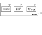
- FIG. 20 shows an example of a functional block diagram of the control device 100 of the present embodiment.
- the control device 100 includes a second acquisition unit 201, a response time calculation unit 202, and a second grouping unit 203.
- the configurations of the second acquisition unit 201, the response time calculation unit 202, and the second grouping unit 203 are the same as those in the first to tenth embodiments.
- the control device 100 of the tenth embodiment performs an operation according to the control signal from the “function for calculating the time difference between the first timepiece and the second timepiece” and “the transmission time of the control signal. It has a function of calculating a response time until the operation time and a function of grouping a plurality of second devices 20 based on the response time (see FIG. 19).
- the control device 100 according to the present embodiment does not have the “function of calculating the time lag between the first clock and the second clock”, that is, the first acquisition unit 101 and the time lag calculation unit 102 are included. It differs from the control apparatus 100 of 10th Embodiment by not having (refer FIG. 20).
- the second grouping unit 203 groups a plurality of second devices 20 based on the response time.
- the second grouping unit 203 generates a group of those having similar response times.
- the grouping method is a design matter.
- the response time may be divided into a group having a predetermined value or more and a group having a response time less than the predetermined value.
- the number of groups is not limited to two and may be more than that.
- the 1st apparatus 10 may select the 2nd apparatus 20 which belongs to a group whose response time is contained in a predetermined range among a plurality of groups as a candidate for a control object.
- This technique is disclosed in Patent Document 1, for example.
- a plurality of storage batteries are grouped based on communication characteristics (communication delay time, packet error rate in communication path, bit error rate in communication path, etc.) between the storage battery and the battery control system.
- a technique for selecting a storage battery included in a group having communication characteristics within a predetermined range as a candidate for an adjustment battery is disclosed.
- “communication characteristics” in the technique disclosed in Patent Document 1 can be replaced with “response time” of the present application.
- the second devices 20 can be grouped based on the response time based on the similar characteristics (response time). For example, the processing load on the first device 10 can be reduced by controlling the plurality of second devices 20 in units of groups rather than individually.
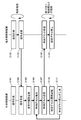
- FIG. 21 shows an overall view of the control system of the present embodiment.
- the control system includes a central control device 11 that transmits a storage battery control signal (eg, LFC (Load Frequency Control) signal, GF (Governor Free) signal), and a plurality of terminal-side control devices that control the storage battery 50 based on the storage battery control signal.
- a storage battery control signal eg, LFC (Load Frequency Control) signal, GF (Governor Free) signal
- the central control device 11 corresponds to the first device 10
- the terminal-side control device 21 corresponds to the second device 20.
- the configurations of the first device 10 and the second device 20 are the same as those in the first to eleventh embodiments.
- the central control device 11 and the plurality of terminal-side control devices 21 are connected via the communication line 30 and can transmit and receive information to and from each other.
- the central control device 11 transmits a storage battery control signal to each of the plurality of terminal-side control devices 21.
- the storage battery control signal is a signal for specifying a command value of output power [W] or charging power [W] of the storage battery, for example.
- the storage battery control signal may indicate the command value itself, or may be a value for calculating the command value. In the latter case, each terminal-side control device 21 calculates a command value based on the storage battery control signal.
- the storage battery control signal may include information (eg, time) indicating the timing of performing a response with the command value.
- Each of the plurality of terminal-side control devices 21 is connected to the corresponding storage battery 50 through a communication line, and inputs a control signal to the corresponding storage battery 50.
- the terminal-side control device 21 specifies a command value based on the storage battery control signal, and causes the storage battery 50 to respond with the specified command value.
- the terminal-side control device 21 sets the storage battery 50 so as to continue the response with the command value specified based on the previous storage battery control signal until the next storage battery control signal is received. You may control.
- the storage battery 50 is connected to the power line 40.
- the storage battery 50 supplies power to the power line 40 with a predetermined output power [W] (output) or receives power from the power line 40 and charges with a predetermined charging power [W] according to the control of the terminal-side control device 21. To do.
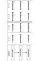
- FIG. 22 shows a basic flow of the control system of this embodiment. As illustrated, it includes “calculation of time lag”, “correction of time lag”, and “calculation of response time”.
- time lag between the first clock used for the central control device 11 and the plurality of second clocks used for each of the plurality of terminal-side control devices 21 is calculated.
- the central control device 11 includes a GPS receiver and can have a function of correcting the time of the first clock based on the GPS signal. In addition, it can also be set as the embodiment in which the central controller 11 does not include a GPS receiver.
- each of the plurality of second clocks used in each of the plurality of terminal-side control devices 21 is corrected to eliminate the time lag between the first clock and the second clock.
- response time is calculated corresponding to each of the plurality of terminal-side control devices 21.
- the response time is the time from the transmission time of the storage battery control signal to the operation time when the operation according to the storage battery control signal is performed.
- central control device 11 or the terminal-side control device 21 performs each of the above three steps, it can be divided into four cases.
- the central control device 11 performs “calculation of time lag”, each terminal side control device 21 performs “correction of time lag”, and each terminal side control device 21 performs “calculation of response time”.
- each terminal-side control device 21 performs “calculation of time lag”, each terminal-side control device 21 performs “correction of time lag”, and the central control device 11 performs “calculation of response time”.
- each terminal-side control device 21 performs “calculation of time lag”, each terminal-side control device 21 performs “correction of time lag”, and each terminal-side control device 21 performs “calculation of response time”. Do.
- FIG. 23 shows an example of a processing flow in which the central controller 11 executes “calculation of time lag”.
- time series data of measured values of predetermined items of the power system is measured.
- the time series data is associated with time information at the time of measurement of each measurement value based on the first clock used in the central controller 11 (first time series data).
- the central controller 11 includes a GPS receiver, and corrects the first clock (time synchronization) based on the GPS signal at a predetermined timing.
- time series data of measured values of predetermined items of the power system is measured.
- the time series data is associated with time information at the time of measurement of each measurement value based on the second clock used in each of the plurality of terminal-side control devices 21 (second time series data).
- the plurality of terminal-side control devices 21 transmit each second time-series data to the central control device 11.
- the central control device 11 receives second time-series data corresponding to each of the plurality of terminal-side control devices 21.
- the central controller 11 accumulates the first time series data and the second time series data.
- the processing from S101 to S105 is repeatedly executed at a cycle of several seconds.
- the processing of S106 to S111 is repeatedly executed at a cycle of several tens of minutes to several hours.
- the central controller 11 determines each of the first timepiece and the plurality of second timepieces based on the first time series data accumulated so far and each of the plurality of second time series data. The time difference with is calculated.
- the central control device 11 transmits a correction instruction including the calculated time lag to each of the plurality of terminal-side control devices 21.
- each terminal-side control device 21 receives a correction instruction including the calculated time lag.
- each terminal-side control device 21 corrects the second clock according to the correction instruction, and eliminates the time lag with respect to the first clock.
- the central control apparatus 11 accumulates the transmission timing (transmission date and time) of the correction instruction and the time lag for each terminal-side control apparatus 21.
- the central controller 11 In S111, the central controller 11 generates estimated information for calculating a time lag from the elapsed time based on the information accumulated in S110.
- the terminal-side control device 21 measures the signal at a cycle of several seconds (S102), and instead of the process of transmitting the signal to the central control device 11 at a cycle of several seconds (S103), measures the signal at a cycle of several seconds.
- the signals may be accumulated, and the accumulated signals may be collectively transmitted to the central controller 11 with a period of several tens of minutes to several hours. Other processing can be the same as described above.
- FIG. 24 shows an example of a processing flow in which each terminal-side control device 21 executes “calculation of time lag”.
- time series data of measured values of predetermined items of the power system is measured.
- the time series data is associated with time information at the time of measurement of each measurement value based on the first clock used in the central controller 11 (first time series data).
- the central controller 11 includes a GPS receiver, and corrects the first clock (time synchronization) based on the GPS signal at a predetermined timing.
- time series data of measured values of predetermined items of the power system is measured.
- the time series data is associated with time information at the time of measurement of each measurement value based on the second clock used in each of the plurality of terminal-side control devices 21 (second time series data).
- the central control device 11 transmits the first time-series data to each of the plurality of terminal-side control devices 21.
- each terminal-side control device 21 receives the first time-series data.
- each terminal-side control device 21 accumulates the first time-series data and the second time-series data.
- the processing from S201 to S205 is repeatedly executed at a cycle of several seconds.
- the processing from S206 to S209 is repeatedly executed at a cycle of several tens of minutes to several hours.
- each terminal-side control device 21 shifts the time between the first clock and the second clock based on the first time-series data and the second time-series data accumulated so far. Is calculated.
- each terminal-side control device 21 corrects the second clock based on the calculated time lag and eliminates the time lag with respect to the first clock.
- each terminal-side control device 21 stores the correction timing (correction date and time) and the time lag.
- each terminal-side control device 21 generates estimated information for calculating a time lag from the elapsed time based on the information accumulated in S208.
- a time lag is calculated based on the estimated information generated in S209 and the elapsed time. Thereafter, the same processing is repeated.
- the central control device 11 measures the signal at a cycle of several seconds (S201), and instead of the process of transmitting the signal to the terminal-side control device 21 at a cycle of several seconds (S203), measures the signal at a cycle of several seconds.
- the signals may be accumulated, and the accumulated signals may be collectively transmitted to the terminal-side control device 21 with a period of several tens of minutes to several hours. Other processing can be the same as described above.
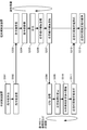
- FIG. 25 shows an example of a processing flow in which the central controller 11 executes “calculation of response time”.
- the central controller 11 calculates a command value.
- the central control device 11 transmits a command value to each terminal-side control device 21.
- the central controller 11 stores the command value and the transmission time in association with each other (third time-series data).
- each terminal-side control device 21 receives the command value.
- each terminal-side control device 21 accumulates the command value.
- each terminal-side control device 21 transmits a control signal to the storage battery 50 and makes it respond with a command value.
- each terminal-side control device 21 measures and accumulates the response value (output power or charging power) of each storage battery 50.
- the response value is stored in association with the time of measurement (fourth time series data).
- S306 is executed after S305, but S306 may be a flow independent of S303 to S305. That is, in S306, regardless of the processing in S303 to S305, the output power or the charging power of each storage battery 50 may be repeatedly measured and stored in association with the time of measurement.
- the processing from S301 to S306 is repeatedly executed at a cycle of several seconds.
- the processing from S307 to S313 is repeatedly executed at a cycle of several tens of minutes to several hours.
- each terminal-side control device 21 transmits the fourth time-series data in which the response value is associated with the measurement time to the central control device 11.
- the central control device 11 receives and accumulates the fourth time-series data from each terminal-side control device 21.
- the central control device 11 determines the response time corresponding to each terminal-side control device 21 based on the third time-series data and each of the fourth time-series data received from each terminal-side control device 21. Calculate an estimate.
- the central controller 11 accumulates the estimated response time calculated for each terminal-side controller 21.
- the central control device 11 transmits an estimated value of the response time calculated corresponding to each terminal-side control device 21 to each terminal-side control device 21.
- each terminal-side control device 21 receives an estimated value of response time.
- each terminal-side control device 21 accumulates the estimated response time.
- the terminal-side control device 21 measures the response value at a cycle of several seconds (S306), and instead of the process of transmitting the response value to the central control device 11 at a cycle of several seconds (S307), measures the response value at a cycle of several seconds,
- the measured response values may be accumulated, and the response values accumulated in a period of several tens of minutes to several hours may be collectively transmitted to the central controller 11.
- Other processing can be the same as described above.
- the terminal-side control device 21 when receiving the command value (S303), the terminal-side control device 21 causes the storage battery 50 to execute a response with the command value without delay in response to the reception (S305).
- a response time may be associated with the command value.
- the terminal side control apparatus 21 may make the storage battery 50 perform the response by a command value, if it detects that it became the response time or the time (time or time) before the response time.
- the terminal-side control device 21 keeps the storage battery 50 at the previous command value until it detects that the response time of the next command value or a time (time or time) a predetermined time before the response time is reached. The response may be continued.
- the central control device 11 calculates a command value corresponding to each terminal-side control device 21 (S301), and executes the following process instead of the process of transmitting the command value (S302). Also good. That is, as described in the eighth embodiment, the central control device 11 may calculate a value for calculating the command value instead of the command value and transmit the value to the terminal-side control device 21. And each terminal side control apparatus 21 may calculate the command value corresponding to self.
- a burden ratio is given to each of the plurality of terminal-side control devices 21 in advance.
- the central control device 11 calculates the value of the output power [W] or the charging power [W] across the plurality of storage batteries 50 in S301, and transmits the value to each terminal-side control device 21 in S302.
- Each terminal-side control device 21 receives the value transmitted in S302 (S303). Then, each terminal-side control device 21 calculates a share ratio given in advance among the values received in S303 as a command value corresponding to itself.
- S311 to S313 may be omitted from the flow.
- a consumer side user who manages the terminal side control apparatus 21
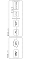
- FIG. 26 shows an example of a processing flow in which each terminal-side control device 21 executes “response time calculation”.
- the central controller 11 calculates a command value.
- the central control device 11 transmits a command value to each terminal-side control device 21.
- the information transmitted here includes the transmission time at which the central controller 11 transmits the command value.
- each terminal-side control device 21 receives the command value.
- each terminal-side control device 21 accumulates the command value and the transmission time (third time-series data).
- each terminal-side control device 21 transmits a control signal to the storage battery 50 and makes it respond with a command value.
- each terminal-side control device 21 measures and stores the response value (output power or charging power) of each storage battery 50.
- the response value is stored in association with the time of measurement (fourth time series data).
- S406 is executed after S405, but S406 may be a flow independent from S403 to S405. That is, in S406, regardless of the processing in S403 to S405, the output power or the charging power of each storage battery 50 may be repeatedly measured and stored in association with the time of measurement.
- the processing from S401 to S406 is repeatedly executed at a cycle of several seconds.
- the processing from S407 to S410 is repeatedly executed at a cycle of several tens of minutes to several hours.
- each terminal-side control device 21 calculates an estimated value of the response time of each terminal-side control device 21 based on the third time-series data and the fourth time-series data.
- each terminal-side control device 21 transmits the calculated estimated response time value to the central control device 11.
- the central controller 11 receives the estimated response time from each terminal-side controller 21.
- the central control device 11 stores the estimated response time in association with each terminal-side control device 21.
- the terminal-side control device 21 when receiving the command value (S403), the terminal-side control device 21 causes the storage battery 50 to execute a response with the command value without delay (S405).
- a response time may be associated with the command value.
- the terminal side control apparatus 21 may make the storage battery 50 perform the response by a command value, if it detects that it became the response time or the time (time or time) before the response time.
- the terminal-side control device 21 keeps the storage battery 50 at the previous command value until it detects that the response time of the next command value or a time (time or time) a predetermined time before the response time is reached. The response may be continued.
- the central control device 11 calculates a command value corresponding to each terminal-side control device 21 (S401), and executes the following process instead of the process of transmitting the command value (S402). Also good. That is, as described in the eighth embodiment, the central control device 11 may calculate a value for calculating the command value instead of the command value and transmit the value to the terminal-side control device 21. And each terminal side control apparatus 21 may calculate the command value corresponding to self.
- a burden ratio is given to each of the plurality of terminal-side control devices 21 in advance.
- the central control device 11 calculates the value of the output power [W] or the charging power [W] for the entire plurality of storage batteries 50 in S401, and transmits the value to each terminal-side control device 21 in S402.
- Each terminal-side control device 21 receives the value transmitted in S402 (S403).
- each terminal-side control device 21 calculates a share ratio given in advance among the values received in S403 as a command value corresponding to itself.
- the control system of the application example has a central system and a terminal system.
- the central system and the terminal system can communicate with each other.
- one terminal side system is shown, but the relationship between the central side system and the terminal side system may be one to plural.
- the central system has a central controller 11, and the terminal system has a terminal controller 21.
- the central system has a central power supply command center system and a cloud server.
- the terminal side system includes a GW (gateway), a local terminal, and an ESS (Energy Storage System).
- the ESS includes a system controller (syscon), a PCS (Power Conditioning System), and a storage battery.
- the central power supply command center system has a central controller 11.
- the system of the central power supply command station calculates a command value or a value for calculating the command value. Then, the central power supply command station system transmits the calculated command value or a storage battery control signal including a value for calculating the command value to the terminal-side system via the cloud server.
- the storage battery control signal may further include a response time.
- the system of the central power supply command station may grasp the current time based on the first clock and determine the response time based on the current time.
- the central power supply command may determine a response time and a command value at that time or a value for calculating the command value based on the response time. For example, the system of the central power supply command station specifies the maximum value Tmax in the response time T corresponding to each of the plurality of terminal-side control devices 21, and the time when Tmax has elapsed from the current time determined based on the first clock. A later time may be determined as the response time.
- the storage battery of the terminal-side system is connected to the power system, and performs power output (reverse power flow) to the power system and power reception (charging) from the power system.
- the PCS controls power output from the storage battery and charging to the storage battery in accordance with a control signal from the system controller.
- the control signal includes a command value (output power [W] / charging power [W]). For example, when receiving a command value from the system controller, the PCS causes the storage battery to execute a response with the command value without delay.
- System controller controls ESS operation.
- the system controller may include the terminal side control device 21.
- the storage battery control signal transmitted from the central system is input to the system controller via the GW and the local terminal.
- you may input into a system controller from GW not via a local terminal.
- the system controller that acquired the storage battery control signal specifies the command value based on the storage battery control signal. Further, the system controller specifies a response time based on the storage battery control signal. Then, the system controller detects that the response time or the time (time or time) that is a predetermined time before the response time is reached based on the current time determined based on the second clock.
- the predetermined time here may be determined based on, for example, the time required from the transmission of the control signal from the system controller to the response of the storage battery.
- the system controller transmits to the PCS a control signal to respond (output / charge) with the command value.
- the PCS When receiving the command value from the system controller, the PCS causes the storage battery to execute a response with the command value without delay.
- the system controller can recognize the command value of the storage battery control signal from the response time based on the storage battery control signal or the current time based on the second clock, a predetermined time before the response time. Until the system controller and PCS detect that the next response time or the time (time or time) a predetermined time before the next response time is detected, the battery controller continues the response with the previous command value. Also good.
- the storage battery control signal may not include the response time.
- the system controller repeatedly receives the storage battery control signal at a predetermined cycle (eg, a cycle of several seconds).
- a predetermined cycle e.g, a cycle of several seconds.
- the system controller specifies the command value without delay and transmits a control signal for responding with the command value to the PCS.
- the PCS causes the storage battery to execute a response with the command value without delay.
- the local terminal may have the terminal-side control device 21.
- the storage battery control signal transmitted from the central system is input to the local terminal via the GW.
- the local terminal that has acquired the storage battery control signal specifies a command value based on the storage battery control signal.
- the local terminal specifies the response time based on the storage battery control signal.
- the local terminal detects that the response time or the time (time or time) before the response time is reached based on the current time determined based on the second clock.
- the predetermined time here may be determined based on, for example, the time required from the transmission of the control signal from the local terminal to the response of the storage battery.
- the local terminal transmits a control signal to respond (output / charge) with the command value to the system controller.
- the system controller When receiving a command value from the local terminal, the system controller transmits a control signal to respond to the command value to the PCS without delay in response to the command value.
- the PCS When receiving the command value from the system controller, the PCS causes the storage battery to execute a response with the command value without delay.
- the system controller can recognize the command value of the storage battery control signal from the response time based on the storage battery control signal or the current time based on the second clock, a predetermined time before the response time.
- the system controller, the PCS, and the local terminal send a response at the previous command value to the storage battery until it detects that the next response time or a time (time or time) a predetermined time before the next response time is reached. It may be continued.
- the storage battery control signal may not include the response time.
- the local terminal repeatedly receives the storage battery control signal at a predetermined cycle (eg, a cycle of several seconds).
- the local terminal specifies a command value without delay and transmits a control signal for responding with the command value to the system controller.
- the system controller receives a control signal including a command value from the local terminal, the system controller transmits a control signal to respond to the command value to the PCS without delay.
- the PCS causes the storage battery to execute a response with the command value without delay.
- the PCS may have the terminal-side control device 21.
- the storage battery control signal transmitted from the central system is input to the PCS via the GW, the local terminal, and the system controller.
- the PCS may be input without going through one or both of the local terminal and the system controller.
- the PCS that has acquired the storage battery control signal specifies a command value based on the storage battery control signal. Moreover, PCS specifies a response time based on the storage battery control signal. Then, the PCS detects that the time (time or time) that is a predetermined time before the response time or the response time is reached based on the current time grasped based on the second clock.
- the predetermined time here may be determined based on, for example, the time required from the start of control by the PCS to the response of the storage battery.
- the PCS causes the storage battery to execute a response with the command value without delay.
- the PCS can recognize the command value of the storage battery control signal from the response time based on the storage battery control signal or the current time based on the second clock, a predetermined time before the response time.
- the PCS may cause the storage battery to continue the response with the previous command value until it detects that the next response time or the time (time or time) before the next response time has come.
- the storage battery control signal may not include the response time.
- the PCS repeatedly receives the storage battery control signal at a predetermined cycle (eg, a cycle of several seconds).
- a predetermined cycle eg, a cycle of several seconds.
- the storage battery control signal is repeatedly transmitted and received at intervals of, for example, 5 seconds.
- the sampling period of the first time series data and the second time series data is preferably 5 seconds or less. Note that the sampling period can be longer than 5 seconds, but in this case, the accuracy of time deviation calculation is degraded.
- control system can be applied to power supply and demand adjustment.
- the control system When the control system is applied to power supply and demand adjustment, the time of the central system and the terminal system can be synchronized. By performing supply and demand adjustment in this state, it is possible to reduce the inconvenience that the terminal side system operates (output / charge) at a timing different from the timing intended by the central system.
- the response time corresponding to each of the plurality of terminal control devices 21 (the operation corresponding to the control signal is performed from the transmission time of the storage battery control signal)
- the response time can be calculated with high accuracy.
- the response time can be determined based on the response time. For example, the maximum value Tmax in the response time T corresponding to each of the plurality of terminal-side control devices 21 is specified, and the time after the time Tlapsed from the current time determined based on the first clock is determined as the response time. can do.
- Tmax in the response time T corresponding to each of the plurality of terminal-side control devices 21 is specified, and the time after the time Tlapsed from the current time determined based on the first clock is determined as the response time. can do.
- the power supply and demand adjustment it is conceivable to pay incentives to the storage battery manager controlled for the adjustment.
- the incentive may be based on the controlled time, controlled power, controlled number of times, etc., but in addition to the storage battery manager who responded accurately (output / charge) at the specified response time.
- a method of paying a higher incentive than the administrator of the storage battery that responds (output / charges) at a timing different from the designated response time can be considered.
- Such a payment method is a motivation for the storage battery manager to adjust its own system so that it can respond according to the response time. As a result, the number of terminal-side systems that respond according to the response time increases, and the accuracy of power supply and demand adjustment improves.
- a first device that transmits a control signal to a second device; and the second device that operates based on the control signal;
- the first device includes: Means for transmitting, to the second device, first time-series data in which time information at the time of measurement is associated with a measured value of a predetermined item of the power system based on a first clock used in the first device.
- the second device includes: Means for receiving the first time-series data; Means for acquiring second time-series data in which time information at the time of measurement is associated with measurement values of the predetermined item of the power system based on a second clock used in the second device; Means for calculating a time lag between the first clock and the second clock based on the first time-series data and the second time-series data; Having a control system.
- ⁇ Second control system> A first device that transmits a control signal to a second device; and the second device that operates based on the control signal;
- the second device includes: Means for transmitting, to the first device, second time-series data in which time information at the time of measurement is associated with a measured value of a predetermined item of the electric power system based on a second clock used in the second device.
- the first device includes: Means for receiving the second time-series data; Means for acquiring first time-series data in which time information at the time of measurement is associated with a measurement value of the predetermined item of the power system based on a first clock used in the first device; Means for calculating a time lag between the first clock and the second clock based on the first time-series data and the second time-series data; Having a control system.
- the first device includes: Means for transmitting, to the second device, third time-series data indicating the content of the control signal and the transmission time from the first device attached based on the first clock;
- the second device includes: Means for receiving the third time-series data; Means for acquiring fourth time-series data indicating the operation content of the second device and the operation time assigned based on the second clock; Means for calculating a response time from a transmission time of the control signal to an operation time at which an operation corresponding to the control signal is performed based on the third time-series data and the fourth time-series data; Having a control system.
- the second device includes: Means for transmitting, to the first device, fourth time-series data indicating an operation content of the second device and an operation time given based on the second clock;
- the first device includes: Means for receiving the fourth time-series data; Means for obtaining third time-series data indicating the content of the control signal and the transmission time from the first device attached based on the first clock; Means for calculating a response time from a transmission time of the control signal to an operation time at which an operation corresponding to the control signal is performed based on the third time-series data and the fourth time-series data; Having a control system.
- the first system is a central control device that transmits a storage battery control signal
- the second device is a terminal-side control device that controls the storage battery based on the storage battery control signal.
- acquisition means that the device itself obtains data or information stored in another device or a storage medium (active acquisition), for example, requests from other devices or Inquiring and receiving, accessing and reading other devices and storage media, etc., and inputting data or information output from other devices to the device (passive acquisition), eg, distribution It includes at least one of receiving data or information (or transmission, push notification, etc.). It also includes selecting and acquiring from received data or information, or selecting and receiving distributed data or information.
- the first time-series data in which the time information at the time of measurement is associated with the measured value of the predetermined item of the power system, and the first time-series data used in the second device.
- First acquisition means for acquiring second time-series data in which time information at the time of measurement is associated with a measurement value of the predetermined item of the power system, based on a clock of 2;
- a time lag calculating means for calculating a time lag between the first clock and the second clock based on the first time series data and the second time series data; Control device.
- control device for calculating the time lag based on the similarity between the waveform of the first time series data and the waveform of the second time series data.
- control device according to The time shift calculation means is a control device that calculates the similarity by moving one waveform on a time axis. 4).
- a control device further comprising correction means for interpolating data into the first time series data and the second time series data. 5).
- the control apparatus which further has an estimation information production
- the first acquisition means acquires a plurality of second time-series data based on a plurality of second clocks used in each of the plurality of second devices,
- the time lag calculating means is configured to calculate a time between the first clock and each of the plurality of second clocks based on the first time series data and each of the plurality of second time series data.
- generation means is a control apparatus which produces
- the time lag calculating means is a control device that calculates the time lag based on the estimation information. 8).
- the control apparatus which further has a transmission means which transmits the correction instruction
- the first device transmits a control signal to the second device; the second device operates based on the control signal; Third time-series data indicating the content of the control signal and the transmission time from the first device attached based on the first clock, the operation content of the second device, and the first Second acquisition means for acquiring fourth time-series data indicating an operation time attached based on the clock of 2; Response time calculation means for calculating a response time from a transmission time of the control signal to an operation time at which an operation corresponding to the control signal is performed based on the third time series data and the fourth time series data
- a control device further comprising: 11.
- Third time series data indicating the content of the control signal and the transmission time from the first device attached based on the first clock used in the first device, and the operation based on the control signal
- Second acquisition means for acquiring fourth time-series data indicating an operation content of the second device and an operation time attached based on a second clock used in the second device
- Response time calculation means for calculating a response time from a transmission time of the control signal to an operation time at which an operation corresponding to the control signal is performed based on the third time series data and the fourth time series data
- Control device. 12 In the control device according to 10 or 11, The control device that calculates the response time based on a similarity between the waveform of the third time series data and the waveform of the fourth time series data. 13.
- the control device is a control apparatus which calculates the said similarity by moving one waveform on a time axis.
- the second acquisition means acquires a plurality of the fourth time-series data based on each of a plurality of second watches used in each of the plurality of second devices,
- the response time calculating means calculates the response time corresponding to each of the second devices based on the third time series data and each of the plurality of fourth time series data. 15.
- a control device further comprising second grouping means for grouping a plurality of the second devices based on the response time. 16.
- the first device is a central control device that transmits a storage battery control signal
- the second device is a terminal-side control device that controls the storage battery based on the storage battery control signal.
- the first device includes: Means for transmitting, to the second device, first time-series data in which time information at the time of measurement is associated with a measured value of a predetermined item of the power system based on a first clock used in the first device.
- the second device includes: Means for receiving the first time-series data; Means for acquiring second time-series data in which time information at the time of measurement is associated with measurement values of the predetermined item of the power system based on a second clock used in the second device; Means for calculating a time lag between the first clock and the second clock based on the first time-series data and the second time-series data; Having a control system. 18.
- the second device includes: Means for transmitting, to the first device, second time-series data in which time information at the time of measurement is associated with a measured value of a predetermined item of the electric power system based on a second clock used in the second device.
- the first device includes: Means for receiving the second time-series data; Means for acquiring first time-series data in which time information at the time of measurement is associated with a measurement value of the predetermined item of the power system based on a first clock used in the first device; Means for calculating a time lag between the first clock and the second clock based on the first time-series data and the second time-series data; Having a control system. 19.
- the first device includes: Means for transmitting, to the second device, third time-series data indicating the content of the control signal and the transmission time from the first device attached based on the first clock;
- the second device includes: Means for receiving the third time-series data; Means for acquiring fourth time-series data indicating the operation content of the second device and the operation time assigned based on the second clock; Means for calculating a response time from a transmission time of the control signal to an operation time at which an operation corresponding to the control signal is performed based on the third time-series data and the fourth time-series data; Having a control system.
- the second device includes: Means for transmitting, to the first device, fourth time-series data indicating an operation content of the second device and an operation time given based on the second clock;
- the first device includes: Means for receiving the fourth time-series data; Means for obtaining third time-series data indicating the content of the control signal and the transmission time from the first device attached based on the first clock; Means for calculating a response time from a transmission time of the control signal to an operation time at which an operation corresponding to the control signal is performed based on the third time-series data and the fourth time-series data; Having a control system. 21.
- the first system is a central control device that transmits a storage battery control signal
- the second device is a terminal-side control device that controls the storage battery based on the storage battery control signal.
- 22. Computer Based on the first clock used in the first device, the first time-series data in which the time information at the time of measurement is associated with the measured value of the predetermined item of the power system, and the first time-series data used in the second device.
- Computer Based on the first clock used in the first device, the first time-series data in which the time information at the time of measurement is associated with the measured value of the predetermined item of the power system, and the first time-series data used in the second device.
- First acquisition means for acquiring second time-series data in which time information at the time of measurement is associated with a measurement value of the predetermined item of the power system based on a clock of 2;
- a time lag calculating means for calculating a time lag between the first clock and the second clock based on the first time series data and the second time series data; Program to function as.
Landscapes
- Engineering & Computer Science (AREA)
- Power Engineering (AREA)
- Electric Clocks (AREA)
- Remote Monitoring And Control Of Power-Distribution Networks (AREA)
Abstract
Provided is a control device (100) having: a first acquisition unit (101) for acquiring first time-series data, wherein measured values of predetermined items of a power system are associated with time information about the times of measurement thereof on the basis of a first clock used by a first device, and second time-series data, wherein measured values of the predetermined items of the power system are associated with time information about the times of measurement thereof on the basis of a second clock used by a second device; and a time lag calculation unit (102) for calculating the time lag between the first clock and the second clock on the basis of the first time-series data and the second time-series data.
Description
本発明は、制御装置、制御システム、制御方法、及びプログラムに関する。
The present invention relates to a control device, a control system, a control method, and a program.
関連する技術が、特許文献1に開示されている。特許文献1には、電力需給調整を行う複数の装置間の時刻同期を、各装置が備えるGPS(Global Positioning System)受信機に基づき実現する技術が開示されている。電力需給調整は、電力系統の需給バランスを保つ処理である。例えば、需要過多の場合には発電装置や蓄電池から電力系統への電力供給を増やし、供給過多の場合には発電装置や蓄電池から電力系統への電力供給を減らしたり、電力を蓄電池に充電したりする。
Related technology is disclosed in Patent Document 1. Patent Document 1 discloses a technique for realizing time synchronization between a plurality of devices that perform power supply and demand adjustment based on a GPS (Global Positioning System) receiver included in each device. The power supply / demand adjustment is a process of maintaining the supply / demand balance of the power system. For example, in the case of excessive demand, the power supply from the power generation device or storage battery to the power system is increased. In the case of excessive supply, the power supply from the power generation device or storage battery to the power system is reduced, or the power is charged to the storage battery. To do.
協働して所定の処理を実行する装置間の時刻同期は、正常に処理を実行する上で必要である。
時刻 Time synchronization between devices that cooperate to execute a predetermined process is necessary to execute the process normally.
例えば、電力需給調整に関わる複数の装置間の時刻同期がなされていないと、需給バランスを保つことができなくなる恐れがある。時刻ずれに起因して、電力系統への電力供給を増やしたいタイミングで電力供給を減らす動作を行ったり、その逆を行ったりということが起こり得る。
For example, if time synchronization between a plurality of devices related to power supply and demand adjustment is not performed, there is a risk that the supply and demand balance cannot be maintained. Due to the time lag, an operation of reducing the power supply may be performed at a timing when the power supply to the power system is to be increased, or vice versa.
近年、電力系統に、自然エネルギー(例:太陽光、風力、地熱等)を利用して発電を行う発電装置が多数接続されている。これらの発電装置の出力は、自然エネルギーの状況に応じ、短時間に変動し得る。このため、電力需給調整の制御内容も短時間に変動し得る。結果、時刻ずれに起因した上述のような不都合が起こりやすくなっている。
In recent years, a large number of power generation devices that generate power using natural energy (eg, sunlight, wind power, geothermal heat, etc.) are connected to the power system. The outputs of these power generators can vary in a short time depending on the state of natural energy. For this reason, the control content of power supply and demand adjustment can also change in a short time. As a result, the above-mentioned inconvenience due to the time lag is likely to occur.
本発明は、装置間の時刻同期を実現するための新たな技術を提供することを課題とする。
An object of the present invention is to provide a new technique for realizing time synchronization between apparatuses.
本発明によれば、
第1の装置で使用される第1の時計に基づき、電力系統の所定項目の測定値に測定時の時刻情報を対応付けた第1の時系列データと、第2の装置で使用される第2の時計に基づき、前記電力系統の前記所定項目の測定値に測定時の時刻情報を対応付けた第2の時系列データと、を取得する第1の取得手段と、
前記第1の時系列データと前記第2の時系列データとに基づき、前記第1の時計と前記第2の時計との間の時刻ずれを算出する時刻ずれ算出手段と、
を有する制御装置が提供される。 According to the present invention,
Based on the first clock used in the first device, the first time-series data in which the time information at the time of measurement is associated with the measured value of the predetermined item of the power system, and the first time-series data used in the second device. First acquisition means for acquiring second time-series data in which time information at the time of measurement is associated with a measurement value of the predetermined item of the power system, based on a clock of 2;
A time lag calculating means for calculating a time lag between the first clock and the second clock based on the first time series data and the second time series data;
A control device is provided.
また、本発明によれば、
制御信号の内容と、第1の装置で使用される第1の時計に基づき付された前記第1の装置からの送信時刻とを示す第3の時系列データ、及び、前記制御信号に基づき動作する第2の装置の動作内容と、前記第2の装置で使用される第2の時計に基づき付された動作時刻とを示す第4の時系列データを取得する第2の取得手段と、
前記第3の時系列データ、及び、前記第4の時系列データに基づき、前記制御信号の送信時刻から当該制御信号に応じた動作が行われる動作時刻までの応答時間を算出する応答時間算出手段と、
を有する制御装置が提供される。 Moreover, according to the present invention,
Third time series data indicating the content of the control signal and the transmission time from the first device attached based on the first clock used in the first device, and the operation based on the control signal Second acquisition means for acquiring fourth time-series data indicating an operation content of the second device and an operation time attached based on a second clock used in the second device;
Response time calculation means for calculating a response time from a transmission time of the control signal to an operation time at which an operation corresponding to the control signal is performed based on the third time series data and the fourth time series data When,
A control device is provided.
また、本発明によれば、
制御信号を第2の装置に送信する第1の装置と、前記制御信号に基づき動作する前記第2の装置とを有し、
前記第1の装置は、
前記第1の装置で使用される第1の時計に基づき、電力系統の所定項目の測定値に測定時の時刻情報を対応付けた第1の時系列データを前記第2の装置に送信する手段を有し、
前記第2の装置は、
前記第1の時系列データを受信する手段と、
前記第2の装置で使用される第2の時計に基づき、電力系統の前記所定項目の測定値に測定時の時刻情報を対応付けた第2の時系列データを取得する手段と、
前記第1の時系列データと前記第2の時系列データとに基づき、前記第1の時計と前記第2の時計との間の時刻ずれを算出する手段と、
を有する制御システムが提供される。 Moreover, according to the present invention,
A first device that transmits a control signal to a second device; and the second device that operates based on the control signal;
The first device includes:
Means for transmitting, to the second device, first time-series data in which time information at the time of measurement is associated with a measured value of a predetermined item of the power system based on a first clock used in the first device. Have
The second device includes:
Means for receiving the first time-series data;
Means for acquiring second time-series data in which time information at the time of measurement is associated with measurement values of the predetermined item of the power system based on a second clock used in the second device;
Means for calculating a time lag between the first clock and the second clock based on the first time-series data and the second time-series data;
A control system is provided.
また、本発明によれば、
制御信号を第2の装置に送信する第1の装置と、前記制御信号に基づき動作する前記第2の装置とを有し、
前記第2の装置は、
前記第2の装置で使用される第2の時計に基づき、電力系統の所定項目の測定値に測定時の時刻情報を対応付けた第2の時系列データを前記第1の装置に送信する手段を有し、
前記第1の装置は、
前記第2の時系列データを受信する手段と、
前記第1の装置で使用される第1の時計に基づき、電力系統の前記所定項目の測定値に測定時の時刻情報を対応付けた第1の時系列データを取得する手段と、
前記第1の時系列データと前記第2の時系列データとに基づき、前記第1の時計と前記第2の時計との間の時刻ずれを算出する手段と、
を有する制御システムが提供される。 Moreover, according to the present invention,
A first device that transmits a control signal to a second device; and the second device that operates based on the control signal;
The second device includes:
Means for transmitting, to the first device, second time-series data in which time information at the time of measurement is associated with a measured value of a predetermined item of the electric power system based on a second clock used in the second device. Have
The first device includes:
Means for receiving the second time-series data;
Means for acquiring first time-series data in which time information at the time of measurement is associated with a measurement value of the predetermined item of the power system based on a first clock used in the first device;
Means for calculating a time lag between the first clock and the second clock based on the first time-series data and the second time-series data;
A control system is provided.
また、本発明によれば、
コンピュータが、
第1の装置で使用される第1の時計に基づき、電力系統の所定項目の測定値に測定時の時刻情報を対応付けた第1の時系列データと、第2の装置で使用される第2の時計に基づき、前記電力系統の前記所定項目の測定値に測定時の時刻情報を対応付けた第2の時系列データと、を取得する第1の取得工程と、
前記第1の時系列データと前記第2の時系列データとに基づき、前記第1の時計と前記第2の時計との間の時刻ずれを算出する時刻ずれ算出工程と、
を実行する制御方法が提供される。 Moreover, according to the present invention,
Computer
Based on the first clock used in the first device, the first time-series data in which the time information at the time of measurement is associated with the measured value of the predetermined item of the power system, and the first time-series data used in the second device. A first acquisition step of acquiring second time-series data in which time information at the time of measurement is associated with a measurement value of the predetermined item of the power system, based on a clock of 2;
A time lag calculating step for calculating a time lag between the first clock and the second clock based on the first time series data and the second time series data;
Is provided.
また、本発明によれば、
コンピュータを、
第1の装置で使用される第1の時計に基づき、電力系統の所定項目の測定値に測定時の時刻情報を対応付けた第1の時系列データと、第2の装置で使用される第2の時計に基づき、前記電力系統の前記所定項目の測定値に測定時の時刻情報を対応付けた第2の時系列データと、を取得する第1の取得手段、
前記第1の時系列データと前記第2の時系列データとに基づき、前記第1の時計と前記第2の時計との間の時刻ずれを算出する時刻ずれ算出手段、
として機能させるプログラムが提供される。 Moreover, according to the present invention,
Computer
Based on the first clock used in the first device, the first time-series data in which the time information at the time of measurement is associated with the measured value of the predetermined item of the power system, and the first time-series data used in the second device. First acquisition means for acquiring second time-series data in which time information at the time of measurement is associated with a measurement value of the predetermined item of the power system based on a clock of 2;
A time lag calculating means for calculating a time lag between the first clock and the second clock based on the first time series data and the second time series data;
A program is provided that functions as:
本発明によれば、装置間の時刻ずれが発生するのを抑制することができる。
According to the present invention, it is possible to suppress time lag between devices.
上述した目的、およびその他の目的、特徴および利点は、以下に述べる好適な実施の形態、およびそれに付随する以下の図面によってさらに明らかになる。
The above-described object and other objects, features, and advantages will be further clarified by a preferred embodiment described below and the following drawings attached thereto.
まず、本実施形態の装置(制御装置)のハードウエア構成の一例について説明する。本実施形態の装置が備える各部は、任意のコンピュータのCPU(Central Processing Unit)、メモリ、メモリにロードされるプログラム、そのプログラムを格納するハードディスク等の記憶ユニット(あらかじめ装置を出荷する段階から格納されているプログラムのほか、CD(Compact Disc)等の記憶媒体やインターネット上のサーバ等からダウンロードされたプログラムをも格納できる)、ネットワーク接続用インターフェイスを中心にハードウエアとソフトウエアの任意の組合せによって実現される。そして、その実現方法、装置にはいろいろな変形例があることは、当業者には理解されるところである。
First, an example of the hardware configuration of the device (control device) of this embodiment will be described. Each unit included in the apparatus of the present embodiment is stored in a CPU (Central Processing Unit), a memory, a program loaded into the memory, a storage unit such as a hard disk storing the program (from the stage of shipping the apparatus in advance). In addition to existing programs, storage media such as CDs (Compact Discs) and programs downloaded from servers on the Internet can also be stored.) Realized by any combination of hardware and software, centering on the network connection interface Is done. It will be understood by those skilled in the art that there are various modifications to the implementation method and apparatus.
図1は、本実施形態の装置のハードウエア構成を例示するブロック図である。図1に示すように、装置は、プロセッサ1A、メモリ2A、入出力インターフェイス3A、周辺回路4A、バス5Aを有する。周辺回路には、様々なモジュールが含まれる。
FIG. 1 is a block diagram illustrating the hardware configuration of the apparatus according to the present embodiment. As shown in FIG. 1, the apparatus includes a processor 1A, a memory 2A, an input / output interface 3A, a peripheral circuit 4A, and a bus 5A. The peripheral circuit includes various modules.
バス5Aは、プロセッサ1A、メモリ2A、周辺回路4A及び入出力インターフェイス3Aが相互にデータを送受信するためのデータ伝送路である。プロセッサ1Aは、例えばCPU(Central Processing Unit) やGPU(Graphics Processing Unit)などの演算処理装置である。メモリ2Aは、例えばRAM(Random Access Memory)やROM(Read Only Memory)などのメモリである。入出力インターフェイス3Aは、外部装置、外部サーバ、外部センサ等から情報を取得するためのインターフェイスなどを含む。プロセッサ1Aは、各モジュールに指令を出し、それらの演算結果をもとに演算を行う。
The bus 5A is a data transmission path through which the processor 1A, the memory 2A, the peripheral circuit 4A, and the input / output interface 3A transmit / receive data to / from each other. The processor 1A is an arithmetic processing device such as a CPU (Central Processing Unit) or a GPU (Graphics Processing Unit). The memory 2A is a memory such as a RAM (Random Access Memory) or a ROM (Read Only Memory). The input / output interface 3A includes an interface for acquiring information from an external device, an external server, an external sensor, and the like. The processor 1A issues a command to each module and performs a calculation based on the calculation result.
以下、本実施の形態について説明する。なお、以下の実施形態の説明において利用する機能ブロック図は、ハードウエア単位の構成ではなく、機能単位のブロックを示している。これらの図においては、各装置は1つの機器により実現されるよう記載されているが、その実現手段はこれに限定されない。すなわち、物理的に分かれた構成であっても、論理的に分かれた構成であっても構わない。なお、同一の構成要素には同一の符号を付し、適宜説明を省略する。
Hereinafter, this embodiment will be described. Note that the functional block diagram used in the following description of the embodiment shows functional unit blocks rather than hardware unit configurations. In these drawings, each device is described as being realized by one device, but the means for realizing it is not limited to this. That is, it may be a physically separated configuration or a logically separated configuration. In addition, the same code | symbol is attached | subjected to the same component and description is abbreviate | omitted suitably.
<第1の実施形態>
まず、図2を用いて、本実施形態の制御システムの全体像及び概要を説明する。本実施形態の制御システムは、第1の装置10と第2の装置20とを有する。第1の装置10及び第2の装置20は、協働して所定の処理を実行する。例えば、第1の装置10は蓄電池制御信号を送信する中央制御装置であり、第2の装置20は蓄電池制御信号に基づき蓄電池を制御する端末側制御装置であるが、これに限定されない。 <First Embodiment>
First, an overview and an outline of the control system of this embodiment will be described with reference to FIG. The control system of the present embodiment includes afirst device 10 and a second device 20. The first device 10 and the second device 20 cooperate to execute a predetermined process. For example, although the 1st apparatus 10 is a central control apparatus which transmits a storage battery control signal, and the 2nd apparatus 20 is a terminal side control apparatus which controls a storage battery based on a storage battery control signal, it is not limited to this.
まず、図2を用いて、本実施形態の制御システムの全体像及び概要を説明する。本実施形態の制御システムは、第1の装置10と第2の装置20とを有する。第1の装置10及び第2の装置20は、協働して所定の処理を実行する。例えば、第1の装置10は蓄電池制御信号を送信する中央制御装置であり、第2の装置20は蓄電池制御信号に基づき蓄電池を制御する端末側制御装置であるが、これに限定されない。 <First Embodiment>
First, an overview and an outline of the control system of this embodiment will be described with reference to FIG. The control system of the present embodiment includes a
第1の装置10は、データを入出力する機能と、データを記憶する機能と、演算処理する機能とを有する。第2の装置20は、同様に、データを入出力する機能と、データを記憶する機能と、演算処理する機能とを有する。第1の装置10及び第2の装置20は、通信線30で互いに繋がり、情報の送受信が可能な状態となっている。
The first device 10 has a function of inputting / outputting data, a function of storing data, and a function of performing arithmetic processing. Similarly, the second device 20 has a function of inputting / outputting data, a function of storing data, and a function of arithmetic processing. The first device 10 and the second device 20 are connected to each other via a communication line 30 and can transmit and receive information.
第1の装置10は、第1の時系列データを取得する。第1の時系列データは、測定センサ60により、所定時間おきに連続的に測定された電力系統(電力線40)の所定項目の値(例:周波数、電流値、電圧値、力率、これらを規格化した値)の時系列データである。第1の時系列データには、第1の装置10で使用される第1の時計に基づき、各値の測定時の時刻情報が対応付けられる。第1の装置10は測定センサ60を有してもよい。また、第1の装置10は第1の時計を有してもよい。
The first device 10 acquires first time series data. The first time series data includes values of predetermined items (eg, frequency, current value, voltage value, power factor, etc.) of the power system (power line 40) continuously measured by the measurement sensor 60 every predetermined time. Time-series data). The first time series data is associated with time information at the time of measurement of each value based on the first clock used in the first device 10. The first device 10 may have a measurement sensor 60. The first device 10 may have a first timepiece.
第2の装置20は、第2の時系列データを取得する。第2の時系列データは、測定センサ70により所定時間おきに連続的に測定された電力系統(電力線40)の所定項目の値(例:周波数、電流値、電圧値、力率、これらを規格化した値)の時系列データである。第2の時系列データには、第2の装置20で使用される第2の時計に基づき、各値の測定時の時刻情報が対応付けられる。第2の装置20は測定センサ70を有してもよい。また、第2の装置20は第2の時計を有してもよい。
The second device 20 acquires second time series data. The second time-series data is a value of a predetermined item (eg, frequency, current value, voltage value, power factor, etc.) of the power system (power line 40) continuously measured by the measurement sensor 70 every predetermined time. Time-series data). The second time series data is associated with time information at the time of measurement of each value based on the second clock used in the second device 20. The second device 20 may have a measurement sensor 70. The second device 20 may include a second timepiece.
測定センサ60の測定位置及び測定センサ70の測定位置は、「電力系統の所定項目の値(例:周波数、電流値、電圧値、力率、これらを規格化した値)の時間変化が概ね同じタイミングで同じ状態となる」という関係を満たす。例えば、日本の場合、西日本と東日本で系統周波数が異なるが、測定センサ60及び測定センサ70は、いずれも、同じ系統周波数のエリアを測定位置とすることができる。より好ましくは、測定センサ60及び測定センサ70は、同じ電力会社管内を測定位置とすることができる。より好ましくは、測定センサ60及び測定センサ70は、同じ電力会社管内における同じ新電力管轄の地域や、同じ配電所から電力供給を受ける区分等を測定位置とすることができる。
The measurement position of the measurement sensor 60 and the measurement position of the measurement sensor 70 are substantially the same as the time changes of the values of the predetermined items of the power system (eg, frequency, current value, voltage value, power factor, values normalized by these). Satisfies the relationship of “same state at timing”. For example, in the case of Japan, the system frequency is different between West Japan and East Japan, but both the measurement sensor 60 and the measurement sensor 70 can use the same system frequency area as the measurement position. More preferably, the measurement sensor 60 and the measurement sensor 70 can be located in the same power company jurisdiction. More preferably, the measurement sensor 60 and the measurement sensor 70 can set the measurement position to a region of the same new power jurisdiction within the same power company jurisdiction, a section to receive power supply from the same distribution station, or the like.
本実施形態の制御装置(図2中、不図示)は、第1の時系列データと第2の時系列データとに基づき、第1の装置10で使用される第1の時計と、第2の装置20で使用される第2の時計との時刻ずれを算出する。本実施形態では、第1の装置10又は第2の装置20が、制御装置を含む。以下、制御装置の構成を詳細に説明する。
The control device (not shown in FIG. 2) of the present embodiment includes a first timepiece used in the first device 10 and a second time series based on the first time-series data and the second time-series data. The time difference from the second clock used in the device 20 is calculated. In the present embodiment, the first device 10 or the second device 20 includes a control device. Hereinafter, the configuration of the control device will be described in detail.
図3に、制御装置100の機能ブロック図の一例を示す。図示するように、制御装置100は、第1の取得部101と、時刻ずれ算出部102とを有する。
FIG. 3 shows an example of a functional block diagram of the control device 100. As illustrated, the control device 100 includes a first acquisition unit 101 and a time shift calculation unit 102.
第1の取得部101は、第1の時系列データと第2の時系列データとを取得する。第1の時系列データは、第1の装置10で使用される第1の時計に基づき、電力系統の所定項目の測定値に測定時の時刻情報を対応付けた時系列データである。第2の時系列データは、第2の装置20で使用される第2の時計に基づき、電力系統の所定項目の測定値に測定時の時刻情報を対応付けた時系列データである。
The first acquisition unit 101 acquires first time series data and second time series data. The first time-series data is time-series data in which time information at the time of measurement is associated with measurement values of predetermined items of the power system based on a first clock used in the first device 10. The second time-series data is time-series data in which time information at the time of measurement is associated with measured values of predetermined items of the power system based on a second clock used in the second device 20.
第1の時系列データ及び第2の時系列データの詳細は、上述の通りである。第1の時系列データ及び第2の時系列データは、同じサンプリング周期で同じ時刻に測定された時系列データであるのが好ましい。
Details of the first time series data and the second time series data are as described above. The first time series data and the second time series data are preferably time series data measured at the same time in the same sampling period.
系統周波数の基準値が50Hzの地域では、1波形の時間間隔が0.02秒である。このため、第1の時系列データ及び第2の時系列データの上記サンプリング周期は、測定対象が電流、電圧及び力率の場合は0.02秒未満、測定対象が系統周波数の場合は0.02秒前後とするのが好ましい。同様に、系統周波数の基準値が60Hzの地域では、1波形の時間間隔が約0.017秒である。このため、第1の時系列データ及び第2の時系列データの上記サンプリング周期は、測定対象が電流、電圧及び力率の場合は0.017秒未満、測定対象が系統周波数の場合は0.017秒前後とするのが好ましい。
In the region where the reference value of the system frequency is 50 Hz, the time interval of one waveform is 0.02 seconds. Therefore, the sampling period of the first time-series data and the second time-series data is less than 0.02 seconds when the measurement target is current, voltage, and power factor, and is 0. 0 when the measurement target is the system frequency. It is preferably about 02 seconds. Similarly, in a region where the reference value of the system frequency is 60 Hz, the time interval of one waveform is about 0.017 seconds. Therefore, the sampling period of the first time-series data and the second time-series data is less than 0.017 seconds when the measurement target is current, voltage and power factor, and is 0. 0 when the measurement target is the system frequency. It is preferable that the time be around 017 seconds.
図4に、第1の時系列データの一例を模式的に示す。図示するように、第1の時系列データは、所定項目の測定値と、各測定値の測定時の時刻とを対応付けたデータである。測定時の時刻は、第1の時計に基づき特定された値である。図5に、第2の時系列データの一例を模式的に示す。図示するように、第2の時系列データも同様に、所定項目の測定値と、各測定値の測定時の時刻とを対応付けたデータである。測定時の時刻は、第2の時計に基づき特定された値である。
FIG. 4 schematically shows an example of the first time series data. As shown in the drawing, the first time series data is data in which measurement values of predetermined items are associated with times at the time of measurement of the respective measurement values. The time at the time of measurement is a value specified based on the first clock. FIG. 5 schematically shows an example of the second time-series data. As shown in the figure, the second time series data is also data in which the measurement values of the predetermined items are associated with the times at the time of measurement of the respective measurement values. The time at the time of measurement is a value specified based on the second clock.
電力系統の所定項目の測定値は、例えば、周波数(系統周波数)、電流値、電圧値、力率、これらを規格化した値等が例示されるが、これらに限定されない。
Examples of the measured value of the predetermined item of the power system include, but are not limited to, a frequency (system frequency), a current value, a voltage value, a power factor, a value obtained by standardizing these, and the like.
図2に示す第1の装置10が制御装置100を有する場合、制御装置100は、第1の時系列データを生成し、第2の装置20から第2の時系列データを受信する。第2の装置20は、例えば数秒周期で測定された測定値を、数秒周期で第1の装置10(制御装置100)に送信してもよい。その他、第2の装置20は、例えば数秒周期で測定された測定値を蓄積し、蓄積された測定値をまとめて、例えば数10分から数時間の周期で第1の装置10(制御装置100)に送信してもよい。当該前提は、以下のすべての実施形態において同様である。
When the first device 10 shown in FIG. 2 includes the control device 100, the control device 100 generates first time series data and receives the second time series data from the second device 20. For example, the second device 20 may transmit measurement values measured at a cycle of several seconds to the first device 10 (the control device 100) at a cycle of several seconds. In addition, the second device 20 accumulates the measured values measured, for example, in a cycle of several seconds, collects the accumulated measured values, and, for example, the first device 10 (control device 100) in a cycle of several tens of minutes to several hours. May be sent to. This assumption is the same in all the following embodiments.
また、図2に示す第2の装置20が制御装置100を有する場合、制御装置100は、第2の時系列データを生成し、第1の装置10から第1の時系列データを受信する。第1の装置10は、例えば数秒周期で測定された測定値を、数秒周期で第2の装置20(制御装置100)に送信してもよい。その他、第1の装置10は、例えば数秒周期で測定された測定値を蓄積し、蓄積された測定値をまとめて、例えば数10分から数時間の周期で第2の装置20(制御装置100)に送信してもよい。当該前提は、以下のすべての実施形態において同様である。
2 has the control device 100, the control device 100 generates second time-series data and receives the first time-series data from the first device 10. For example, the first device 10 may transmit measurement values measured at a cycle of several seconds to the second device 20 (the control device 100) at a cycle of several seconds. In addition, the first device 10 accumulates measurement values measured, for example, in a cycle of several seconds, and collects the accumulated measurement values, for example, the second device 20 (control device 100) in a cycle of several tens of minutes to several hours. May be sent to. This assumption is the same in all the following embodiments.
図3に戻り、時刻ずれ算出部102は、第1の時系列データと第2の時系列データとに基づき、第1の時計と第2の時計との間の時刻ずれを算出する。
Referring back to FIG. 3, the time lag calculation unit 102 calculates the time lag between the first clock and the second clock based on the first time series data and the second time series data.
時刻ずれ算出部102は、第1の時系列データの波形、及び、第2の時系列データの波形の類似度に基づき、時刻ずれを算出する。
The time lag calculation unit 102 calculates the time lag based on the similarity between the waveform of the first time series data and the waveform of the second time series data.
なお、時刻ずれ算出部102は、第1の時系列データの中の所定時間分のデータによる波形、及び、第2の時系列データの中の上記所定時間分のデータによる波形の類似度に基づき、時刻ずれを算出することができる。上記所定時間は、波形の大まかな傾向(ノイズを除くトレンド成分)が分かる範囲で定めることができる設計的事項である。
Note that the time lag calculation unit 102 is based on the waveform similarity based on the predetermined time data in the first time series data and the waveform similarity based on the predetermined time data in the second time series data. The time lag can be calculated. The predetermined time is a design matter that can be determined within a range in which a rough tendency of the waveform (a trend component excluding noise) can be understood.
図6に、第1の時系列データ、及び、第2の時系列データをグラフ上にプロットした図を示す。横軸は時刻であり、縦軸は系統周波数である。
FIG. 6 shows a diagram in which the first time series data and the second time series data are plotted on a graph. The horizontal axis is time, and the vertical axis is system frequency.
時刻ずれ算出部102は、一方の波形を時間軸上でずらしながら(移動しながら)、2つの波形間の類似度を算出する。ずらす時間は、第1の時系列データ、及び、第2の時系列データのサンプリング周期を整数倍した値である。そして、時刻ずれ算出部102は、類似度が所定レベル以上となった時のずらした時間tを、第1の時計と第2の時計との間の時刻ずれとして算出する。
The time shift calculation unit 102 calculates the similarity between two waveforms while shifting (moving) one waveform on the time axis. The shifting time is a value obtained by multiplying the sampling period of the first time series data and the second time series data by an integer. Then, the time shift calculation unit 102 calculates the shifted time t when the similarity is equal to or higher than a predetermined level as the time shift between the first clock and the second clock.
時刻ずれ算出部102は、第1の時系列データ、及び、第2の時系列データの相関係数を、上記類似度として算出してもよい。この場合、時刻ずれ算出部102は、相関係数が所定値以上となった時のずらした時間tを、第1の時計と第2の時計との間の時刻ずれとして算出する。
The time lag calculation unit 102 may calculate the correlation coefficient of the first time series data and the second time series data as the similarity. In this case, the time shift calculation unit 102 calculates the shifted time t when the correlation coefficient is equal to or greater than a predetermined value as the time shift between the first clock and the second clock.
その他、一方の時系列データから他方の時系列データを引いた差の時系列データ(対応するタイミング毎に、一方の値から他方の値を引いた差を時系列に並べたデータ)を、上記類似度として算出してもよい。この場合、時刻ずれ算出部102は、例えば、差の時系列データに含まれる複数の値の統計値(例:最大値、平均値)が所定値以下となった時のずらした時間tを、第1の時計と第2の時計との間の時刻ずれとして算出してもよい。
In addition, the time-series data of the difference obtained by subtracting the other time-series data from one time-series data (the data obtained by arranging the difference obtained by subtracting the other value from one value in time series for each corresponding timing) The similarity may be calculated. In this case, for example, the time lag calculation unit 102 calculates the shifted time t when a statistical value (eg, maximum value, average value) of a plurality of values included in the time series data of the difference is equal to or less than a predetermined value, You may calculate as a time gap between the 1st timepiece and the 2nd timepiece.
時刻ずれ算出部102は、ずらす時間tnを徐々に大きくしながら、または、小さくしながら、各々に対応する類似度を算出し、類似度と所定値との比較を行ってもよい。この場合、類似度算出及び比較の回数が多くなる傾向となる。そこで、例えば、時刻ずれ算出部102は、次のようなアルゴリズムを採用してもよい。
The time shift calculation unit 102 may calculate the similarity corresponding to each while gradually increasing or decreasing the shift time tn and compare the similarity with a predetermined value. In this case, the number of times of similarity calculation and comparison tends to increase. Thus, for example, the time lag calculation unit 102 may employ the following algorithm.
例えば、ずらす時間の候補がt1からt10の10通りある場合(t1<t2<t3・・・<t9<t10)、これらを、値の順に複数のグループに分けてもよい。ここでは、t1乃至t5のグループと、t6乃至t10の2つのグループに分けるとする。そして、時刻ずれ算出部102は、各グループの1つの代表メンバー(例:t3及びt8)各々に対応する類似度を算出する。算出した類似度のうちのいずれか一方が所定値以上である場合、時刻ずれ算出部102は、そのずらした時間を時刻ずれとする。
For example, when there are ten candidates for the shift time from t1 to t10 (t1 <t2 <t3... <T9 <t10), these may be divided into a plurality of groups in the order of the values. Here, it is assumed that the group is divided into t1 to t5 groups and two groups t6 to t10. Then, the time lag calculation unit 102 calculates the degree of similarity corresponding to each representative member (eg, t3 and t8) of each group. If any one of the calculated similarities is equal to or greater than a predetermined value, the time shift calculation unit 102 sets the shifted time as the time shift.
一方、いずれの類似度も所定値未満である場合、時刻ずれ算出部102は、類似度がより高い方のグループを特定する。そして、特定したグループに属するメンバー各々に対して類似度の算出、及び、所定値との比較を行う。特定したグループのメンバー各々の類似度を算出してもよいし、特定したグループのメンバーを上記と同様にグループ化し、同様の処理を行ってもよい。当該方法によれば、類似度算出及び比較の回数を減らすことができる。
On the other hand, if any of the similarities is less than the predetermined value, the time lag calculation unit 102 identifies the group with the higher similarity. Then, the degree of similarity is calculated for each member belonging to the specified group and compared with a predetermined value. The degree of similarity of each member of the specified group may be calculated, or the members of the specified group may be grouped in the same manner as described above and the same processing may be performed. According to this method, the number of similarity calculations and comparisons can be reduced.
なお、第1の装置10と第2の装置20との関係は、1対1でもよく、又は、1対複数であってもよい。当該前提は、以下のすべての実施形態において同様である。
Note that the relationship between the first device 10 and the second device 20 may be one-to-one or may be one-to-multiple. This assumption is the same in all the following embodiments.
1対複数の場合、第1の取得部101は、第1の装置10で使用される第1の時計に基づき、電力系統の所定項目の測定値に測定時の時刻情報を対応付けた第1の時系列データと、複数の第2の装置20各々で使用される複数の第2の時計各々に基づき、電力系統の所定項目の測定値に測定時の時刻情報を対応付けた複数の第2の時系列データと、を取得する。そして、時刻ずれ算出部102は、第1の時系列データと、複数の第2の時系列データ各々とに基づき、第1の時計と、複数の第2の時計各々との間の時刻ずれを算出する。
In the case of one-to-multiple, the first acquisition unit 101 associates time information at the time of measurement with measurement values of predetermined items of the power system based on the first timepiece used in the first device 10. Based on the time-series data and the plurality of second clocks used in each of the plurality of second devices 20, a plurality of second times in which time information at the time of measurement is associated with measured values of predetermined items of the power system. And time-series data. Then, the time lag calculation unit 102 calculates a time lag between the first clock and each of the plurality of second clocks based on the first time series data and each of the plurality of second time series data. calculate.
また、第1の装置10のみGPS受信機を備え、GPS信号に基づき第1の時計の時刻補正を行う機能を備えてもよい。当該第1の時計と、1つ又は複数の第2の時計との時刻ずれを算出することで、1つ又は複数の第2の時計の時刻ずれを正確に算出することができる。当該前提は、以下のすべての実施形態において同様である。
Further, only the first device 10 may be provided with a GPS receiver, and may have a function of correcting the time of the first clock based on the GPS signal. By calculating the time difference between the first timepiece and one or more second timepieces, the time difference between the one or more second timepieces can be accurately calculated. This assumption is the same in all the following embodiments.
次に、図7のフローチャートを用いて、本実施形態の制御装置100の処理の流れの一例を説明する。
Next, an example of the flow of processing of the control device 100 of this embodiment will be described using the flowchart of FIG.
まず、第1の取得部101は、第1の装置10で使用される第1の時計に基づき、電力系統の所定項目の測定値に測定時の時刻情報を対応付けた第1の時系列データと、第2の装置20で使用される第2の時計に基づき、電力系統の所定項目の測定値に測定時の時刻情報を対応付けた第2の時系列データと、を取得する(S10)。
First, the first acquisition unit 101 is based on a first clock used in the first device 10, and first time-series data in which time information at the time of measurement is associated with measurement values of predetermined items of the power system. And based on the 2nd timepiece used with the 2nd apparatus 20, the 2nd time series data which matched time information at the time of measurement with the measured value of the predetermined item of an electric power system is acquired (S10). .
次に、時刻ずれ算出部102は、第1の時系列データと第2の時系列データとに基づき、第1の時計と第2の時計との間の時刻ずれを算出する。
Next, the time lag calculation unit 102 calculates the time lag between the first clock and the second clock based on the first time series data and the second time series data.
以上説明した本実施形態によれば、装置間の時刻ずれを算出する新たな技術が実現される。このようにして算出した時刻ずれに基づき時計の時刻の修正を行うことで、当該装置間の時刻同期が実現される。本実施形態によれば、新たな時刻同期の技術が実現される。
According to the present embodiment described above, a new technique for calculating the time lag between devices is realized. By correcting the time of the clock based on the time lag calculated in this way, time synchronization between the devices is realized. According to the present embodiment, a new time synchronization technique is realized.
本実施形態の場合、各装置がGPS受信機等の高価な装置を備える必要がない。このため、本実施形態の時刻同期実現方法は、コスト面で優れる。
In the case of this embodiment, it is not necessary for each device to include an expensive device such as a GPS receiver. For this reason, the time synchronization realization method of this embodiment is excellent in cost.
また、本実施形態では、第1の時系列データの波形と、第2の時系列データの波形との類似度に基づき、時刻ずれを算出することができる。電力系統の所定項目の測定値は、同じ値が連続する場合がある。このため、ある時点の測定値のみで第1の時系列データと第2の時系列データの類似度を算出し、時刻ずれを算出した場合、誤った時刻ずれを算出する可能性がある。第1の時系列データの波形と、第2の時系列データの波形との類似度に基づき時刻ずれを算出することができる本実施形態の場合、時刻ずれの算出精度を高めることができる。
In this embodiment, the time lag can be calculated based on the similarity between the waveform of the first time series data and the waveform of the second time series data. The measured value of the predetermined item of the power system may be the same value continuously. For this reason, when the similarity between the first time-series data and the second time-series data is calculated using only measured values at a certain time point, and a time lag is calculated, there is a possibility of calculating an incorrect time lag. In the present embodiment in which the time lag can be calculated based on the similarity between the waveform of the first time-series data and the waveform of the second time-series data, the time lag calculation accuracy can be increased.
本実施形態の変形例として、第1の装置10及び第2の装置20と物理的及び/又は論理的に分かれた第3の装置が、制御装置100を有してもよい。第3の装置は、第1の装置10及び第2の装置20から第1の時系列データ及び第2の時系列データを受信し、それらに基づき、第1の時計と第2の時計との間の時刻ずれを算出する。
As a modification of the present embodiment, a third device that is physically and / or logically separated from the first device 10 and the second device 20 may include the control device 100. The third device receives the first time-series data and the second time-series data from the first device 10 and the second device 20, and based on them, the first timepiece and the second timepiece The time difference between them is calculated.
<第2の実施形態>
本実施形態の制御装置100は、第1の時系列データ及び第2の時系列データを補正する機能を有する。例えば、第1の時系列データ及び第2の時系列データのサンプリング周期が検出したい時刻ずれの最小値より大きい場合、所望の時刻ずれを検出できない。制御装置100は、第1の時系列データ及び第2の時系列データにデータを補間することでサンプリング周期を補正し、所望の時刻ずれを検出できるようにする。以下、説明する。 <Second Embodiment>
Thecontrol device 100 according to the present embodiment has a function of correcting the first time series data and the second time series data. For example, when the sampling period of the first time-series data and the second time-series data is larger than the minimum value of the time shift to be detected, a desired time shift cannot be detected. The control device 100 corrects the sampling period by interpolating the data into the first time series data and the second time series data so that a desired time lag can be detected. This will be described below.
本実施形態の制御装置100は、第1の時系列データ及び第2の時系列データを補正する機能を有する。例えば、第1の時系列データ及び第2の時系列データのサンプリング周期が検出したい時刻ずれの最小値より大きい場合、所望の時刻ずれを検出できない。制御装置100は、第1の時系列データ及び第2の時系列データにデータを補間することでサンプリング周期を補正し、所望の時刻ずれを検出できるようにする。以下、説明する。 <Second Embodiment>
The
図8に、本実施形態の制御装置100の機能ブロック図の一例を示す。図示するように、制御装置100は、第1の取得部101と、時刻ずれ算出部102と、補正部103とを有する。第1の取得部101及び時刻ずれ算出部102の構成は、第1の実施形態と同様である。
FIG. 8 shows an example of a functional block diagram of the control device 100 of the present embodiment. As illustrated, the control device 100 includes a first acquisition unit 101, a time shift calculation unit 102, and a correction unit 103. The configurations of the first acquisition unit 101 and the time shift calculation unit 102 are the same as those in the first embodiment.
補正部103は、第1の時系列データ及び第2の時系列データにデータを補間する。
The correction unit 103 interpolates data into the first time series data and the second time series data.
第1の取得部101は、第1の時系列データ及び第2の時系列データを補正部103に入力する。補正部103は、予め保持しているサンプリング周期の基準値に基づき、補間が必要か否かを判断する。
The first acquisition unit 101 inputs the first time series data and the second time series data to the correction unit 103. The correction unit 103 determines whether interpolation is necessary based on a reference value of a sampling period that is held in advance.
補正部103は、「サンプリング周期が基準値以下」を満たす場合、当該第1の時系列データ及び第2の時系列データに対する補間は不要と判断する。そして、補正部103は、当該第1の時系列データ及び第2の時系列データを、そのまま、時刻ずれ算出部102に入力する。
The correction unit 103 determines that the interpolation for the first time-series data and the second time-series data is unnecessary when the “sampling period is equal to or less than the reference value”. Then, the correction unit 103 inputs the first time series data and the second time series data to the time shift calculation unit 102 as they are.
一方、補正部103は、「サンプリング周期が基準値以下」を満たさない場合、当該第1の時系列データ及び第2の時系列データに対する補間は必要と判断する。そして、補正部103は、当該第1の時系列データ及び第2の時系列データに対して補間処理を行った後、補間処理後の第1の時系列データ及び第2の時系列データを時刻ずれ算出部102に入力する。
On the other hand, when the “sampling period does not satisfy the reference value or less”, the correction unit 103 determines that interpolation for the first time series data and the second time series data is necessary. Then, the correction unit 103 performs an interpolation process on the first time-series data and the second time-series data, and then converts the first time-series data and the second time-series data after the interpolation process to a time Input to the deviation calculation unit 102.
補正部103は、あらゆる技術を採用して、データを補間することができる。例えば、スプライン補間等が例示される。補正部103は、例えば、前後のデータの値に基づきその間のデータの値を推測し、推測値を補間してもよい。
The correction unit 103 can employ any technique to interpolate data. For example, spline interpolation is exemplified. For example, the correcting unit 103 may estimate the data value between the preceding and subsequent data values and interpolate the estimated value.
時刻ずれ算出部102は、補正部103から入力されたデータに基づき、第1の時計と第2の時計との間の時刻ずれを算出する。
The time lag calculation unit 102 calculates the time lag between the first clock and the second clock based on the data input from the correction unit 103.
以上説明した本実施形態によれば、第1の実施形態と同様な作用効果を実現できる。また、本実施形態によれば、第1の時系列データ及び第2の時系列データにデータを補間することで、検出可能な時刻ずれの分解能を高め、所望の時刻ずれを算出できるようになる。
According to the present embodiment described above, the same operational effects as those of the first embodiment can be realized. Further, according to the present embodiment, by interpolating data into the first time-series data and the second time-series data, it becomes possible to increase the resolution of the detectable time lag and calculate the desired time lag. .
また、類似性の統計指標(相関、誤差)を計算する際に、第1の時系列データ及び第2の時系列データいずれかの波形データに欠損(例えば、データ送受信時)が生じると、双方のサンプリング数が一致せず、類似性を計算できなくなる。本実施形態で説明したようにデータの補間を行うことで、欠損部分を補うことができる。結果、データの欠損が発生した場合であっても、類似性の計算が可能になる。
In addition, when calculating the statistical index (correlation, error) of similarity, if there is a defect (for example, at the time of data transmission / reception) in the waveform data of either the first time-series data or the second time-series data, both The sampling numbers of do not match, and similarity cannot be calculated. By performing data interpolation as described in the present embodiment, a missing portion can be compensated. As a result, even if data loss occurs, similarity can be calculated.
<第3の実施形態>
本実施形態の制御システムは、算出した時刻ずれに基づき第2の時計を補正し、第1の時計と第2の時計とを同期させる機能をさらに有する。以下、説明する。なお、本実施形態では、図2に示す第1の装置10が制御装置100を有するものとする。 <Third Embodiment>
The control system of the present embodiment further has a function of correcting the second clock based on the calculated time lag and synchronizing the first clock and the second clock. This will be described below. In the present embodiment, it is assumed that thefirst device 10 shown in FIG.
本実施形態の制御システムは、算出した時刻ずれに基づき第2の時計を補正し、第1の時計と第2の時計とを同期させる機能をさらに有する。以下、説明する。なお、本実施形態では、図2に示す第1の装置10が制御装置100を有するものとする。 <Third Embodiment>
The control system of the present embodiment further has a function of correcting the second clock based on the calculated time lag and synchronizing the first clock and the second clock. This will be described below. In the present embodiment, it is assumed that the
図9に、本実施形態の制御装置100の機能ブロック図の一例を示す。図示するように、制御装置100は、第1の取得部101と、時刻ずれ算出部102と、送信部104とを有する。なお、図示しないが、制御装置100は、さらに、補正部103を有してもよい。第1の取得部101、時刻ずれ算出部102及び補正部103の構成は、第1及び第2の実施形態と同様である。
FIG. 9 shows an example of a functional block diagram of the control device 100 of the present embodiment. As illustrated, the control device 100 includes a first acquisition unit 101, a time shift calculation unit 102, and a transmission unit 104. Although not shown, the control device 100 may further include a correction unit 103. The configurations of the first acquisition unit 101, the time shift calculation unit 102, and the correction unit 103 are the same as those in the first and second embodiments.
送信部104は、算出された時刻ずれに基づき第2の時計を修正させる修正指示を第2の装置20に送信する。修正指示は、時刻ずれの内容(進んでいる時間、又は、遅れている時間)を含む。
The transmission unit 104 transmits to the second device 20 a correction instruction for correcting the second clock based on the calculated time difference. The correction instruction includes the contents of the time lag (the progress time or the delay time).
修正指示を受信した第2の装置20は、修正指示に従い第2の時計を修正し、第1の時計との間の時刻ずれを解消する。
The second device 20 that has received the correction instruction corrects the second clock according to the correction instruction, and eliminates the time lag with respect to the first clock.
以上説明した本実施形態によれば、第1及び第2の実施形態と同様な作用効果を実現できる。また、本実施形態によれば、第2の時計を修正することで、第1の時計と第2の時計とを同期させることができる。
According to the present embodiment described above, the same operational effects as those of the first and second embodiments can be realized. Further, according to the present embodiment, the first clock and the second clock can be synchronized by correcting the second clock.
<第4の実施形態>
本実施形態の制御システムは、算出した時刻ずれに基づき第2の時計を補正し、第1の時計と第2の時計とを同期させる機能をさらに有する。以下、説明する。なお、本実施形態では、図2に示す第2の装置20が制御装置100を有するものとする。 <Fourth Embodiment>
The control system of the present embodiment further has a function of correcting the second clock based on the calculated time lag and synchronizing the first clock and the second clock. This will be described below. In the present embodiment, it is assumed that thesecond device 20 shown in FIG.
本実施形態の制御システムは、算出した時刻ずれに基づき第2の時計を補正し、第1の時計と第2の時計とを同期させる機能をさらに有する。以下、説明する。なお、本実施形態では、図2に示す第2の装置20が制御装置100を有するものとする。 <Fourth Embodiment>
The control system of the present embodiment further has a function of correcting the second clock based on the calculated time lag and synchronizing the first clock and the second clock. This will be described below. In the present embodiment, it is assumed that the
図10に、本実施形態の制御装置100の機能ブロック図の一例を示す。図示するように、制御装置100は、第1の取得部101と、時刻ずれ算出部102と、修正部107とを有する。なお、図示しないが、制御装置100は、さらに、補正部103を有してもよい。第1の取得部101、時刻ずれ算出部102及び補正部103の構成は、第1乃至第3の実施形態と同様である。
FIG. 10 shows an example of a functional block diagram of the control device 100 of the present embodiment. As illustrated, the control device 100 includes a first acquisition unit 101, a time lag calculation unit 102, and a correction unit 107. Although not shown, the control device 100 may further include a correction unit 103. The configurations of the first acquisition unit 101, the time shift calculation unit 102, and the correction unit 103 are the same as those in the first to third embodiments.
修正部107は、算出された時刻ずれに基づき第2の時計を修正し、第1の時計との間の時刻ずれを解消する。
The correction unit 107 corrects the second clock based on the calculated time lag, and eliminates the time lag with the first clock.
以上説明した本実施形態によれば、第1及び第2の実施形態と同様な作用効果を実現できる。また、本実施形態によれば、第2の時計を補正することで、第1の時計と第2の時計とを同期させることができる。
According to the present embodiment described above, the same operational effects as those of the first and second embodiments can be realized. Further, according to the present embodiment, the first clock and the second clock can be synchronized by correcting the second clock.
<第5の実施形態>
本実施形態の制御システムは、経過時間及びその間に生じた時刻ずれを示す過去実績に基づき、経過時間から時刻ずれを算出する推定情報を生成する機能をさらに有する。以下、説明する。なお、本実施形態では、図2に示す第1の装置10が制御装置100を有するものとする。すなわち、第1の装置10が、推定情報を生成する。そして、第1の装置10が、推定情報と経過時間とに基づき、時刻ずれを算出する。 <Fifth Embodiment>
The control system according to the present embodiment further has a function of generating estimation information for calculating the time shift from the elapsed time based on the past performance indicating the elapsed time and the time shift generated during that time. This will be described below. In the present embodiment, it is assumed that thefirst device 10 shown in FIG. That is, the first device 10 generates estimation information. Then, the first device 10 calculates a time lag based on the estimated information and the elapsed time.
本実施形態の制御システムは、経過時間及びその間に生じた時刻ずれを示す過去実績に基づき、経過時間から時刻ずれを算出する推定情報を生成する機能をさらに有する。以下、説明する。なお、本実施形態では、図2に示す第1の装置10が制御装置100を有するものとする。すなわち、第1の装置10が、推定情報を生成する。そして、第1の装置10が、推定情報と経過時間とに基づき、時刻ずれを算出する。 <Fifth Embodiment>
The control system according to the present embodiment further has a function of generating estimation information for calculating the time shift from the elapsed time based on the past performance indicating the elapsed time and the time shift generated during that time. This will be described below. In the present embodiment, it is assumed that the
図11に、本実施形態の制御装置100の機能ブロック図の一例を示す。図示するように、制御装置100は、第1の取得部101と、時刻ずれ算出部102と、送信部104と、推定情報生成部105とを有する。なお、図示しないが、制御装置100は、さらに、補正部103を有してもよい。第1の取得部101、時刻ずれ算出部102、補正部103及び送信部104の構成は、第1乃至第4の実施形態と同様である。
FIG. 11 shows an example of a functional block diagram of the control device 100 of the present embodiment. As illustrated, the control device 100 includes a first acquisition unit 101, a time shift calculation unit 102, a transmission unit 104, and an estimated information generation unit 105. Although not shown, the control device 100 may further include a correction unit 103. The configurations of the first acquisition unit 101, the time shift calculation unit 102, the correction unit 103, and the transmission unit 104 are the same as those in the first to fourth embodiments.
推定情報生成部105は、経過時間、及び、経過時間の間に生じた時刻ずれを示す過去実績に基づき、経過時間から時刻ずれを算出する推定情報を生成する。
The estimated information generation unit 105 generates estimated information for calculating the time lag from the elapsed time based on the elapsed time and the past results indicating the time lag generated during the elapsed time.
時刻ずれ算出部102は、所定周期(数10分から数時間の周期)で繰り返し第1の時計と第2の時計との時刻ずれを算出する。そして、送信部104は、その都度、算出された時刻ずれに基づく修正指示を第2の装置20に送信する。
The time lag calculation unit 102 repeatedly calculates the time lag between the first clock and the second clock at a predetermined cycle (a cycle of several tens of minutes to several hours). Then, the transmission unit 104 transmits a correction instruction based on the calculated time lag to the second device 20 each time.
上記経過時間は、n回目の上記処理から(n+1)回目の上記処理までの経過時間である。経過時間の間に生じた時刻ずれは、(n+1)回目の上記処理で算出された時刻ずれである。
The elapsed time is an elapsed time from the nth process to the (n + 1) th process. The time lag occurring during the elapsed time is the time lag calculated in the (n + 1) th process.
経過時間の始点及び終点をどのタイミングにするかは設計的事項である。上記例の場合、例えば、n回目の上記処理で修正指示を第2の装置20に送信したタイミングを、経過時点の始点としてもよい。その他、第1の装置10は、修正指示を第2の装置20に送信した後、第2の時計の修正を完了したことを示す完了通知を第2の装置20から受信してもよい。そして、第1の装置10は、当該受信タイミングを、経過時点の始点としてもよい。
It is a design matter to determine the timing of the start and end points of elapsed time. In the case of the above example, for example, the timing at which the correction instruction is transmitted to the second device 20 in the n-th process may be set as the starting point of the elapsed time. In addition, after transmitting the correction instruction to the second device 20, the first device 10 may receive a completion notification indicating that the correction of the second clock has been completed from the second device 20. And the 1st apparatus 10 is good also considering the said reception timing as the starting point of elapsed time.
また、(n+1)回目の上記処理で時刻ずれを算出するタイミングを、経過時間の終点としてもよい。
Also, the timing at which the time lag is calculated in the (n + 1) th process may be the end point of the elapsed time.
このような過去実績が、制御装置100内、又は、制御装置100と通信可能に構成された外部装置内に蓄積される。第1の装置10と第2の装置20の関係が1対複数である場合、複数の第2の装置20各々に対応付けて、過去実績が蓄積される。
Such past results are stored in the control device 100 or in an external device configured to be able to communicate with the control device 100. When the relationship between the first device 10 and the second device 20 is one-to-multiple, past results are accumulated in association with each of the plurality of second devices 20.
推定情報生成部105は、このような過去実績に基づき、経過時間から時刻ずれを算出する推定情報(例:推定式)を生成する。推定情報の生成方法は設計的事項であり、例えば、回帰分析等の手法を採用することができる。
The estimation information generation unit 105 generates estimation information (eg, estimation formula) for calculating a time lag from the elapsed time based on such past results. The generation method of the estimation information is a design matter, and for example, a method such as regression analysis can be adopted.
時刻ずれ算出部102は、推定情報が生成された後、推定情報と、上記経過時間とに基づき、第1の時計と第2の時計との間の時刻ずれを算出することができる。
The time lag calculating unit 102 can calculate the time lag between the first clock and the second clock based on the estimated information and the elapsed time after the estimated information is generated.
以上説明した本実施形態によれば、第1乃至第4の実施形態と同様の作用効果を実現できる。また、本実施形態によれば、経過時間と推定情報とに基づき、第1の時計と第2の時計との間の時刻ずれを算出することができる。推定情報生成後、第1の時系列データ及び第2の時系列データに基づく算出方法を、経過時間及び推定情報に基づく算出方法に置き代えることで、コンピュータの演算負担を軽減することができる。
According to the present embodiment described above, the same operational effects as those of the first to fourth embodiments can be realized. Further, according to the present embodiment, it is possible to calculate the time difference between the first clock and the second clock based on the elapsed time and the estimated information. After the estimation information is generated, the calculation method based on the first time series data and the second time series data is replaced with a calculation method based on the elapsed time and the estimation information, so that the calculation burden on the computer can be reduced.
<第6の実施形態>
本実施形態の制御システムは、第1の装置10と第2の装置20の関係が1対複数である。本実施形態の制御システムは、第5の実施形態で説明した過去実績に基づき、複数の第2の装置20各々で使用される複数の第2の時計をグループ化する。そして、グループ毎に、各グループ内で共通の推定情報を生成する機能をさらに有する。以下、説明する。なお、本実施形態では、図2に示す第1の装置10が制御装置100を有するものとする。 <Sixth Embodiment>
In the control system of this embodiment, the relationship between thefirst device 10 and the second device 20 is one-to-multiple. The control system of the present embodiment groups a plurality of second clocks used in each of the plurality of second devices 20 based on the past results described in the fifth embodiment. And it has further the function which produces | generates the estimation information common within each group for every group. This will be described below. In the present embodiment, it is assumed that the first device 10 shown in FIG.
本実施形態の制御システムは、第1の装置10と第2の装置20の関係が1対複数である。本実施形態の制御システムは、第5の実施形態で説明した過去実績に基づき、複数の第2の装置20各々で使用される複数の第2の時計をグループ化する。そして、グループ毎に、各グループ内で共通の推定情報を生成する機能をさらに有する。以下、説明する。なお、本実施形態では、図2に示す第1の装置10が制御装置100を有するものとする。 <Sixth Embodiment>
In the control system of this embodiment, the relationship between the
図12に、本実施形態の制御装置100の機能ブロック図の一例を示す。図示するように、制御装置100は、第1の取得部101と、時刻ずれ算出部102と、送信部104と、推定情報生成部105と、第1のグループ化部106とを有する。なお、図示しないが、制御装置100は、さらに、補正部103を有してもよい。第1の取得部101、時刻ずれ算出部102、補正部103及び送信部104の構成は、第1乃至第5の実施形態と同様である。
FIG. 12 shows an example of a functional block diagram of the control device 100 of the present embodiment. As illustrated, the control device 100 includes a first acquisition unit 101, a time lag calculation unit 102, a transmission unit 104, an estimated information generation unit 105, and a first grouping unit 106. Although not shown, the control device 100 may further include a correction unit 103. The configurations of the first acquisition unit 101, the time shift calculation unit 102, the correction unit 103, and the transmission unit 104 are the same as those in the first to fifth embodiments.
第1のグループ化部106は、過去実績に基づき、複数の第2の装置20各々で使用される複数の第2の時計をグループ化する。過去実績は、第5の実施形態で説明した通り、経過時間と、経過時間の間に生じた時刻ずれと、を示すデータである。
The first grouping unit 106 groups a plurality of second clocks used in each of the plurality of second devices 20 based on past results. As described in the fifth embodiment, the past performance is data indicating the elapsed time and the time lag generated between the elapsed times.
第1のグループ化部106は、時刻ずれの傾向が似ている第2の時計どうしでグループを作成する。グループ化の手法は設計的事項である。例えば、経過時間mの際の時刻ずれが所定値以上のグループと、所定値未満のグループに分けてもよい。なお、グループの数は、2つに限定されず、それ以上であってもよい。
The first grouping unit 106 creates a group of second clocks having similar time shift trends. The grouping method is a design matter. For example, the time lag at the elapsed time m may be divided into a group having a predetermined value or more and a group having a predetermined value or less. The number of groups is not limited to two and may be more than that.
推定情報生成部105は、グループ毎に、各グループ内で共通の推定情報を生成する。すなわち、推定情報生成部105は、第2の時計ごとに推定情報を生成するのでなく、グループ毎に推定情報を生成する。
The estimation information generation unit 105 generates estimation information common to each group for each group. That is, the estimated information generation unit 105 does not generate estimated information for each second clock, but generates estimated information for each group.
例えば、推定情報生成部105は、グループ毎に、各グループの複数のメンバー(第2の時計)の過去実績のすべて又は一部に基づき、経過時間から時刻ずれを算出する推定情報(例:推定式)を生成する。推定情報の生成方法は設計的事項であり、例えば、回帰分析等の手法を採用することができる。
For example, the estimation information generation unit 105 estimates, for each group, estimation information that calculates a time lag from the elapsed time based on all or part of past results of a plurality of members (second clocks) of each group (example: estimation) Expression). The generation method of the estimation information is a design matter, and for example, a method such as regression analysis can be adopted.
時刻ずれ算出部102は、推定情報が生成された後、推定情報と、上記経過時間とに基づき、第1の時計と第2の時計との間の時刻ずれを算出することができる。時刻ずれ算出部102は、第2の時計各々の時刻ずれを、第2の時計各々が属するグループに対応して生成された推定情報に基づき、算出する。
The time lag calculating unit 102 can calculate the time lag between the first clock and the second clock based on the estimated information and the elapsed time after the estimated information is generated. The time lag calculation unit 102 calculates the time lag of each of the second clocks based on the estimation information generated corresponding to the group to which each of the second clocks belongs.
以上説明した本実施形態によれば、第1乃至第5の実施形態と同様な作用効果を実現できる。また、本実施形態によれば、第2の時計を、時刻ずれの生じ方が似ているものどうしでグループ化し、グループ毎に、推定情報を生成することができる。このため、複数の第2の時計各々に対応して推定情報を生成する場合に比べて、コンピュータの処理負担を軽減できる。
According to the present embodiment described above, the same operational effects as those of the first to fifth embodiments can be realized. In addition, according to the present embodiment, it is possible to group the second clocks with similar time shifts and generate estimation information for each group. For this reason, compared with the case where estimation information is produced | generated corresponding to each of several 2nd timepiece, the processing burden of a computer can be reduced.
<第7の実施形態>
本実施形態の制御システムは、経過時間及びその間の時刻ずれを示す過去実績に基づき、経過時間から時刻ずれを算出する推定情報を生成する機能をさらに有する。以下、説明する。なお、本実施形態では、図2に示す第2の装置20が制御装置100を有するものとする。すなわち、第2の装置20が、推定情報を生成する。そして、第2の装置20が、推定情報と経過時間とに基づき、時刻ずれを算出する。 <Seventh Embodiment>
The control system of the present embodiment further has a function of generating estimation information for calculating a time shift from the elapsed time based on past results indicating the elapsed time and the time shift therebetween. This will be described below. In the present embodiment, it is assumed that thesecond device 20 shown in FIG. That is, the second device 20 generates estimation information. Then, the second device 20 calculates a time lag based on the estimated information and the elapsed time.
本実施形態の制御システムは、経過時間及びその間の時刻ずれを示す過去実績に基づき、経過時間から時刻ずれを算出する推定情報を生成する機能をさらに有する。以下、説明する。なお、本実施形態では、図2に示す第2の装置20が制御装置100を有するものとする。すなわち、第2の装置20が、推定情報を生成する。そして、第2の装置20が、推定情報と経過時間とに基づき、時刻ずれを算出する。 <Seventh Embodiment>
The control system of the present embodiment further has a function of generating estimation information for calculating a time shift from the elapsed time based on past results indicating the elapsed time and the time shift therebetween. This will be described below. In the present embodiment, it is assumed that the
図13に、本実施形態の制御装置100の機能ブロック図の一例を示す。図示するように、制御装置100は、第1の取得部101と、時刻ずれ算出部102と、推定情報生成部105と、修正部107とを有する。なお、図示しないが、制御装置100は、さらに、補正部103を有してもよい。第1の取得部101、時刻ずれ算出部102、補正部103及び修正部107の構成は、第1乃至第6の実施形態と同様である。
FIG. 13 shows an example of a functional block diagram of the control device 100 of the present embodiment. As illustrated, the control device 100 includes a first acquisition unit 101, a time lag calculation unit 102, an estimated information generation unit 105, and a correction unit 107. Although not shown, the control device 100 may further include a correction unit 103. The configurations of the first acquisition unit 101, the time shift calculation unit 102, the correction unit 103, and the correction unit 107 are the same as those in the first to sixth embodiments.
推定情報生成部105は、経過時間、及び、経過時間の間に生じた時刻ずれを示す過去実績に基づき、経過時間から時刻ずれを算出する推定情報を生成する。
The estimated information generation unit 105 generates estimated information for calculating the time lag from the elapsed time based on the elapsed time and the past results indicating the time lag generated during the elapsed time.
時刻ずれ算出部102は、所定周期(数10分から数時間の周期)で繰り返し第1の時計と第2の時計との時刻ずれを算出する。そして、修正部107は、その都度、算出された時刻ずれに基づき第2の時計を修正する。
The time lag calculation unit 102 repeatedly calculates the time lag between the first clock and the second clock at a predetermined cycle (a cycle of several tens of minutes to several hours). Then, the correction unit 107 corrects the second timepiece based on the calculated time difference each time.
上記経過時間は、n回目の上記処理から(n+1)回目の上記処理までの経過時間である。経過時間の間に生じた時刻ずれは、(n+1)回目の上記処理で算出された時刻ずれである。
The elapsed time is an elapsed time from the nth process to the (n + 1) th process. The time lag occurring during the elapsed time is the time lag calculated in the (n + 1) th process.
経過時間の始点及び終点をどのタイミングにするかは設計的事項である。上記例の場合、例えば、n回目の上記処理で第2の時計を修正したタイミングを、経過時点の始点としてもよい。そして、(n+1)回目の上記処理で時刻ずれを算出するタイミングを、経過時間の終点としてもよい。
It is a design matter to determine the timing of the start and end points of elapsed time. In the case of the above example, for example, the timing at which the second clock is corrected in the n-th process may be set as the starting point of the elapsed time. The timing at which the time lag is calculated in the (n + 1) th process may be the end point of the elapsed time.
このような過去実績が、制御装置100内、又は、制御装置100と通信可能に構成された外部装置内に蓄積される。第1の装置10と第2の装置20の関係が1対複数である場合、第2の装置20各々が備える各制御装置100内、又は、各制御装置100と通信可能に構成された外部装置内に各々の過去実績が蓄積される。
Such past results are stored in the control device 100 or in an external device configured to be able to communicate with the control device 100. When the relationship between the first device 10 and the second device 20 is one-to-multiple, each control device 100 included in each second device 20 or an external device configured to be able to communicate with each control device 100 Each past performance is accumulated in the inside.
推定情報生成部105は、このような過去実績に基づき、経過時間から時刻ずれを算出する推定情報(例:推定式)を生成する。推定情報の生成方法は設計的事項であり、例えば、回帰分析等の手法を採用することができる。
The estimation information generation unit 105 generates estimation information (eg, estimation formula) for calculating a time lag from the elapsed time based on such past results. The generation method of the estimation information is a design matter, and for example, a method such as regression analysis can be adopted.
時刻ずれ算出部102は、推定情報が生成された後、推定情報と、上記経過時間とに基づき、第1の時計と第2の時計との間の時刻ずれを算出することができる。
The time lag calculating unit 102 can calculate the time lag between the first clock and the second clock based on the estimated information and the elapsed time after the estimated information is generated.
以上説明した本実施形態によれば、第1乃至第4の実施形態と同様の作用効果を実現できる。また、本実施形態によれば、経過時間と推定情報とに基づき、第1の時計と第2の時計との間の時刻ずれを算出することができる。推定情報生成後、第1の時系列データ及び第2の時系列データに基づく算出方法を、経過時間及び推定情報に基づく算出方法に置き代えることで、コンピュータの演算負担を軽減することができる。
According to the present embodiment described above, the same operational effects as those of the first to fourth embodiments can be realized. Further, according to the present embodiment, it is possible to calculate the time difference between the first clock and the second clock based on the elapsed time and the estimated information. After the estimation information is generated, the calculation method based on the first time series data and the second time series data is replaced with a calculation method based on the elapsed time and the estimation information, so that the calculation burden on the computer can be reduced.
<第8の実施形態>
本実施形態の制御システムでは、図2に示す第1の装置10は制御信号を第2の装置20に送信する。そして、第2の装置20は制御信号に基づき動作する。そして、制御装置100は、第1の装置10による制御信号の送信から、第2の装置20による制御信号に応じた動作が行われるまでの応答時間を算出する機能をさらに有する。以下、説明する。 <Eighth Embodiment>
In the control system of the present embodiment, thefirst device 10 shown in FIG. 2 transmits a control signal to the second device 20. The second device 20 operates based on the control signal. The control device 100 further has a function of calculating a response time from the transmission of the control signal by the first device 10 until the operation according to the control signal by the second device 20 is performed. This will be described below.
本実施形態の制御システムでは、図2に示す第1の装置10は制御信号を第2の装置20に送信する。そして、第2の装置20は制御信号に基づき動作する。そして、制御装置100は、第1の装置10による制御信号の送信から、第2の装置20による制御信号に応じた動作が行われるまでの応答時間を算出する機能をさらに有する。以下、説明する。 <Eighth Embodiment>
In the control system of the present embodiment, the
図14に、本実施形態の制御装置100の機能ブロック図の一例を示す。図示するように、制御装置100は、第1の取得部101と、時刻ずれ算出部102と、第2の取得部201と、応答時間算出部202とを有する。なお、図示しないが、制御装置100は、さらに、補正部103、送信部104、推定情報生成部105、第1のグループ化部106及び修正部107の中の1つ又は複数をさらに有してもよい。第1の取得部101、時刻ずれ算出部102、補正部103、送信部104、推定情報生成部105、第1のグループ化部106及び修正部107の構成は、第1乃至第7の実施形態と同様である。
FIG. 14 shows an example of a functional block diagram of the control device 100 of the present embodiment. As illustrated, the control device 100 includes a first acquisition unit 101, a time lag calculation unit 102, a second acquisition unit 201, and a response time calculation unit 202. Although not shown, the control apparatus 100 further includes one or more of a correction unit 103, a transmission unit 104, an estimation information generation unit 105, a first grouping unit 106, and a correction unit 107. Also good. The configurations of the first acquisition unit 101, time shift calculation unit 102, correction unit 103, transmission unit 104, estimation information generation unit 105, first grouping unit 106, and correction unit 107 are the first to seventh embodiments. It is the same.
第2の取得部201は、第3の時系列データ及び第4の時系列データを取得する。第3の時系列データは、第1の装置10から第2の装置20に送信される制御信号の内容と、第1の時計に基づき付された第1の装置10からの送信時刻とを示す。第4の時系列データは、第2の装置20の動作内容と、第2の時計に基づき付された動作時刻とを示す。
The second acquisition unit 201 acquires the third time series data and the fourth time series data. The third time series data indicates the content of the control signal transmitted from the first device 10 to the second device 20 and the transmission time from the first device 10 attached based on the first clock. . The fourth time-series data indicates the operation content of the second device 20 and the operation time assigned based on the second clock.
第1の装置10が蓄電池制御信号(制御信号)を送信する中央制御装置であり、第2の装置20が蓄電池制御信号(制御信号)に基づき蓄電池を制御する端末側制御装置である場合、蓄電池制御信号(制御信号)の内容は、例えば、蓄電池の出力電力[W]又は充電電力[W]の指令値である。そして、第2の装置20の動作内容は、第2の装置20の制御で動作した蓄電池の出力電力[W]又は充電電力[W]の測定値(応答値)である。図15及び16に、このような第3の時系列データ及び第4の時系列データの一例を模式的に示す。
When the first device 10 is a central control device that transmits a storage battery control signal (control signal) and the second device 20 is a terminal-side control device that controls the storage battery based on the storage battery control signal (control signal), the storage battery The content of the control signal (control signal) is, for example, a command value for the output power [W] or the charging power [W] of the storage battery. The operation content of the second device 20 is a measured value (response value) of the output power [W] or the charging power [W] of the storage battery operated under the control of the second device 20. FIGS. 15 and 16 schematically show examples of such third time-series data and fourth time-series data.
なお、蓄電池制御信号(制御信号)の内容は、蓄電池の出力電力[W]又は充電電力[W]の指令値を算出するための値であってもよい。例えば、予め、複数の第2の装置20各々に負担割合を特定するための情報が与えられる。そして、蓄電池制御信号(制御信号)として、複数の蓄電池全体での出力電力[W]又は充電電力[W]の値が各第2の装置20に送信される。ここで複数の第2の装置20に送信される内容は同じ内容であるので、例えばブロードキャスト等で一斉送信してもよい。各第2の装置20は、複数の蓄電池全体での出力電力[W]又は充電電力[W]の値の中の自身の負担割合分を、指令値として算出する。蓄電池制御信号(制御信号)の内容に関する当該前提は、以下のすべての実施形態において同様である。このような場合であっても、蓄電池制御信号(制御信号)の内容が指令値の場合と、同様の作用効果を実現できる。
The content of the storage battery control signal (control signal) may be a value for calculating a command value for the output power [W] or the charging power [W] of the storage battery. For example, information for specifying the burden ratio is given to each of the plurality of second devices 20 in advance. Then, as the storage battery control signal (control signal), the value of the output power [W] or the charging power [W] of the entire plurality of storage batteries is transmitted to each second device 20. Here, since the contents transmitted to the plurality of second devices 20 are the same contents, they may be transmitted simultaneously by broadcast or the like. Each second device 20 calculates its own share of the output power [W] or charging power [W] of the plurality of storage batteries as a command value. The premise regarding the contents of the storage battery control signal (control signal) is the same in all of the following embodiments. Even in such a case, it is possible to realize the same effect as the case where the content of the storage battery control signal (control signal) is a command value.
第1の装置10が第3の時系列データを生成し、第2の装置20が第4の時系列データを生成する。
The first device 10 generates third time series data, and the second device 20 generates fourth time series data.
図2に示す第1の装置10が制御装置100を有する場合、制御装置100は、第3の時系列データを生成し、第2の装置20から第4の時系列データを受信する。第2の装置20は、例えば数秒周期で測定された応答値を、数秒周期で第1の装置10(制御装置100)に送信してもよい。その他、第2の装置20は、例えば数秒周期で測定された応答値を蓄積し、蓄積された応答値をまとめて、例えば数10分から数時間の周期で第1の装置10(制御装置100)に送信してもよい。当該前提は、以下のすべての実施形態において同様である。
When the first device 10 shown in FIG. 2 includes the control device 100, the control device 100 generates third time series data and receives the fourth time series data from the second device 20. For example, the second device 20 may transmit a response value measured at a cycle of several seconds to the first device 10 (the control device 100) at a cycle of several seconds. In addition, the second device 20 accumulates response values measured, for example, in a cycle of several seconds, and collects the accumulated response values, for example, the first device 10 (control device 100) in a cycle of several tens of minutes to several hours, for example. May be sent to. This assumption is the same in all the following embodiments.
第2の装置20が制御装置100を有する場合、制御装置100は、第4の時系列データを生成し、第1の装置10から第3の時系列データを受信する。
When the second device 20 includes the control device 100, the control device 100 generates fourth time-series data and receives the third time-series data from the first device 10.
応答時間算出部202は、第3の時系列データ、及び、第4の時系列データに基づき、制御信号の送信時刻から当該制御信号に応じた動作が行われる動作時刻までの応答時間を算出する。
The response time calculation unit 202 calculates the response time from the transmission time of the control signal to the operation time when the operation corresponding to the control signal is performed based on the third time series data and the fourth time series data. .
応答時間算出部202は、第3の時系列データの波形、及び、第4の時系列データの波形の類似度に基づき、応答時間を算出する。
The response time calculation unit 202 calculates a response time based on the similarity between the waveform of the third time series data and the waveform of the fourth time series data.
なお、応答時間算出部202は、第3の時系列データの中の所定時間分のデータによる波形、及び、第4の時系列データの中の上記所定時間分のデータによる波形の類似度に基づき、時刻ずれを算出することができる。上記所定時間は、波形の大まかな傾向(ノイズを除くトレンド成分)が分かる範囲で定めることができる設計的事項である。
Note that the response time calculation unit 202 is based on a waveform based on data for a predetermined time in the third time-series data and a waveform similarity based on the data for the predetermined time in the fourth time-series data. The time lag can be calculated. The predetermined time is a design matter that can be determined within a range in which a rough tendency of the waveform (a trend component excluding noise) can be understood.
図17に、第3の時系列データ、及び、第4の時系列データをグラフ上にプロットした図を示す。横軸は時刻であり、縦軸は指令値及び応答値を所定条件で規格化した値である。
FIG. 17 shows a diagram in which the third time-series data and the fourth time-series data are plotted on a graph. The horizontal axis is time, and the vertical axis is a value obtained by standardizing command values and response values under predetermined conditions.
応答時間算出部202は、一方の波形を時間軸上でずらしながら(移動しながら)、2つの波形間の類似度を算出する。ずらす時間は、第3の時系列データ、及び、第4の時系列データのサンプリング周期を整数倍した値である。そして、応答時間算出部202は、類似度が所定レベル以上となった時のずらした時間t´を、応答時間として算出する。
The response time calculation unit 202 calculates the similarity between two waveforms while shifting one waveform on the time axis (moving). The shifting time is a value obtained by multiplying the sampling period of the third time series data and the fourth time series data by an integer. Then, the response time calculation unit 202 calculates the shifted time t ′ when the similarity is equal to or higher than a predetermined level as the response time.
応答時間算出部202は、第3の時系列データ、及び、第4の時系列データの相関係数を、上記類似度として算出してもよい。この場合、応答時間算出部202は、相関係数が所定値以上となった時のずらした時間t´を、応答時間として算出する。
The response time calculation unit 202 may calculate the correlation coefficient of the third time series data and the fourth time series data as the similarity. In this case, the response time calculation unit 202 calculates the shifted time t ′ when the correlation coefficient is equal to or greater than a predetermined value as the response time.
その他、一方の時系列データから他方の時系列データを引いた差の時系列データ(対応するタイミング毎に、一方の値から他方の値を引いた差を時系列に並べたデータ)を、上記類似度として算出してもよい。この場合、応答時間算出部202は、例えば、差の時系列データに含まれる複数の値の統計値(例:最大値、平均値)が所定値以下となった時のずらした時間t´を、応答時間として算出してもよい。
In addition, the time-series data of the difference obtained by subtracting the other time-series data from one time-series data (the data obtained by arranging the difference obtained by subtracting the other value from one value in time series for each corresponding timing) The similarity may be calculated. In this case, for example, the response time calculation unit 202 calculates a shifted time t ′ when a statistical value (eg, maximum value, average value) of a plurality of values included in the time series data of the difference is equal to or less than a predetermined value. The response time may be calculated.
第1の装置10と第2の装置20との関係が1対複数の場合、第2の取得部201は、第1の装置10で使用される第1の時計に基づく第3の時系列データと、複数の第2の装置20各々で使用される複数の第2の時計各々に基づく複数の第4の時系列データと、を取得する。そして、応答時間算出部202は、第3の時系列データと、複数の第4の時系列データ各々とに基づき、複数の第2の装置20各々に対応して応答時間を算出する。
When the relationship between the first device 10 and the second device 20 is one-to-multiple, the second acquisition unit 201 uses third time-series data based on the first clock used in the first device 10. And a plurality of fourth time series data based on each of the plurality of second clocks used in each of the plurality of second devices 20. Then, the response time calculation unit 202 calculates a response time corresponding to each of the plurality of second devices 20 based on the third time series data and each of the plurality of fourth time series data.
以上説明した本実施形態によれば、第1乃至第7の実施形態と同様の作用効果を実現できる。また、本実施形態によれば、第1の装置10から制御信号が送信された送信時刻から、当該制御信号に応じた第2の装置20による動作が行われる動作時刻までの応答時間を算出することができる。第1乃至第7の実施形態で説明した手法で、第1の装置10で使用される第1の時計と、第2の装置20で使用される第2の時計との時刻同期を行っておくことで、応答時間を高精度に算出することができる。
According to the present embodiment described above, the same operational effects as those of the first to seventh embodiments can be realized. Further, according to the present embodiment, the response time from the transmission time at which the control signal is transmitted from the first device 10 to the operation time at which the operation by the second device 20 corresponding to the control signal is performed is calculated. be able to. With the method described in the first to seventh embodiments, time synchronization between the first clock used in the first device 10 and the second clock used in the second device 20 is performed. Thus, the response time can be calculated with high accuracy.
また、本実施形態では、第3の時系列データの波形と、第4の時系列データの波形との類似度に基づき、応答時間を算出することができる。指令値及び応答値は、同じ値が連続する場合がある。このため、ある時点の指令値及び応答値のみで第3の時系列データと第4の時系列データの類似度を算出し、応答時間を算出した場合、誤った応答時間を算出する可能性がある。第3の時系列データの波形と、第4の時系列データの波形との類似度に基づき応答時間を算出することができる本実施形態の場合、応答時間の算出精度を高めることができる。
In the present embodiment, the response time can be calculated based on the similarity between the waveform of the third time series data and the waveform of the fourth time series data. The command value and the response value may be the same value in succession. For this reason, when the similarity between the third time-series data and the fourth time-series data is calculated using only the command value and the response value at a certain point in time and the response time is calculated, there is a possibility of calculating an incorrect response time. is there. In the case of this embodiment in which the response time can be calculated based on the similarity between the waveform of the third time series data and the waveform of the fourth time series data, the calculation accuracy of the response time can be increased.
<第9の実施形態>
本実施形態の制御システムでは、第1の装置10は制御信号を第2の装置20に送信する。そして、第2の装置20は制御信号に基づき動作する。そして、第1の時計と第2の時計との間の時刻ずれを算出する制御装置100と物理的及び/又は論理的に分かれた制御装置200が、制御信号の送信時刻から当該制御信号に応じた動作が行われる動作時刻までの応答時間を算出する。すなわち、本実施形態では、「第1の時計と第2の時計との間の時刻ずれを算出する制御装置100」と、「制御信号の送信時刻から当該制御信号に応じた動作が行われる動作時刻までの応答時間を算出する制御装置200」とが、物理的及び/又は論理的に分かれている。 <Ninth Embodiment>
In the control system of the present embodiment, thefirst device 10 transmits a control signal to the second device 20. The second device 20 operates based on the control signal. Then, the control device 100 that calculates the time difference between the first timepiece and the second timepiece and the control device 200 that is physically and / or logically separated responds to the control signal from the transmission time of the control signal. The response time until the operation time at which the operation is performed is calculated. That is, in this embodiment, “the control device 100 that calculates the time difference between the first timepiece and the second timepiece” and “the operation in which the operation according to the control signal is performed from the transmission time of the control signal” The control device 200 "for calculating the response time up to the time is physically and / or logically separated.
本実施形態の制御システムでは、第1の装置10は制御信号を第2の装置20に送信する。そして、第2の装置20は制御信号に基づき動作する。そして、第1の時計と第2の時計との間の時刻ずれを算出する制御装置100と物理的及び/又は論理的に分かれた制御装置200が、制御信号の送信時刻から当該制御信号に応じた動作が行われる動作時刻までの応答時間を算出する。すなわち、本実施形態では、「第1の時計と第2の時計との間の時刻ずれを算出する制御装置100」と、「制御信号の送信時刻から当該制御信号に応じた動作が行われる動作時刻までの応答時間を算出する制御装置200」とが、物理的及び/又は論理的に分かれている。 <Ninth Embodiment>
In the control system of the present embodiment, the
図3に、制御装置100の機能ブロック図の一例を示す。図示するように、制御装置100は、第1の取得部101と、時刻ずれ算出部102とを有する。図示しないが、制御装置100は、さらに、補正部103、送信部104、推定情報生成部105、第1のグループ化部106及び修正部107の中の1つ又は複数をさらに有してもよい。第1の取得部101、時刻ずれ算出部102、補正部103、送信部104、推定情報生成部105、第1のグループ化部106及び修正部107の構成は、第1乃至第8の実施形態と同様である。
FIG. 3 shows an example of a functional block diagram of the control device 100. As illustrated, the control device 100 includes a first acquisition unit 101 and a time shift calculation unit 102. Although not shown, the control device 100 may further include one or more of a correction unit 103, a transmission unit 104, an estimation information generation unit 105, a first grouping unit 106, and a correction unit 107. . The configurations of the first acquisition unit 101, the time shift calculation unit 102, the correction unit 103, the transmission unit 104, the estimation information generation unit 105, the first grouping unit 106, and the correction unit 107 are the first to eighth embodiments. It is the same.
図18に、制御装置200の機能ブロック図の一例を示す。図示するように、制御装置200は、第2の取得部201と、応答時間算出部202とを有する。第2の取得部201及び応答時間算出部202の構成は、第8の実施形態と同様である。
FIG. 18 shows an example of a functional block diagram of the control device 200. As illustrated, the control device 200 includes a second acquisition unit 201 and a response time calculation unit 202. The configurations of the second acquisition unit 201 and the response time calculation unit 202 are the same as those in the eighth embodiment.
本実施形態では、図2に示す第1の装置10及び第2の装置20の一方が制御装置100を有し、他方が制御装置200を有する。例えば、第1の装置10が制御装置100を有し、第2の装置20が制御装置200を有してもよい。または、第2の装置20が制御装置100を有し、第2の装置20が制御装置100を有してもよい。
In the present embodiment, one of the first device 10 and the second device 20 shown in FIG. 2 has the control device 100, and the other has the control device 200. For example, the first device 10 may include the control device 100 and the second device 20 may include the control device 200. Alternatively, the second device 20 may include the control device 100, and the second device 20 may include the control device 100.
以上、説明した本実施形態によれば、第1乃至第8の実施形態と同様の作用効果を実現できる。また、時刻ずれの算出、及び、応答時間の算出を、第1の装置10と第2の装置20とに分けることができる。このため、一方に処理負担が集中する不都合を回避できる。
As described above, according to the present embodiment described above, the same functions and effects as those of the first to eighth embodiments can be realized. Further, the calculation of the time lag and the calculation of the response time can be divided into the first device 10 and the second device 20. For this reason, the inconvenience that the processing load is concentrated on one side can be avoided.
<第10の実施形態>
本実施形態の制御装置100は、第8の実施形態の構成を基本とし、さらに、算出した応答時間に基づき複数の第2の装置20をグループ化する機能を有する。以下、説明する。 <Tenth Embodiment>
Thecontrol device 100 of the present embodiment is based on the configuration of the eighth embodiment, and further has a function of grouping a plurality of second devices 20 based on the calculated response time. This will be described below.
本実施形態の制御装置100は、第8の実施形態の構成を基本とし、さらに、算出した応答時間に基づき複数の第2の装置20をグループ化する機能を有する。以下、説明する。 <Tenth Embodiment>
The
図19に、本実施形態の制御装置100の機能ブロック図の一例を示す。図示するように、制御装置100は、第1の取得部101と、時刻ずれ算出部102と、第2の取得部201と、応答時間算出部202と、第2のグループ化部203とを有する。図示しないが、制御装置100は、さらに、補正部103、送信部104、推定情報生成部105、第1のグループ化部106及び修正部107の中の1つ又は複数を有してもよい。第1の取得部101、時刻ずれ算出部102、補正部103、送信部104、推定情報生成部105、第1のグループ化部106、修正部107、第2の取得部201及び応答時間算出部202の構成は、第1乃至第9の実施形態と同様である。
FIG. 19 shows an example of a functional block diagram of the control device 100 of the present embodiment. As illustrated, the control device 100 includes a first acquisition unit 101, a time lag calculation unit 102, a second acquisition unit 201, a response time calculation unit 202, and a second grouping unit 203. . Although not shown, the control apparatus 100 may further include one or more of a correction unit 103, a transmission unit 104, an estimation information generation unit 105, a first grouping unit 106, and a correction unit 107. First acquisition unit 101, time shift calculation unit 102, correction unit 103, transmission unit 104, estimated information generation unit 105, first grouping unit 106, correction unit 107, second acquisition unit 201, and response time calculation unit The configuration 202 is the same as in the first to ninth embodiments.
第2のグループ化部203は、応答時間に基づき、複数の第2の装置20をグループ化する。第2のグループ化部203は、応答時間が類似するものどうしでグループを生成する。グループ化の手法は設計的事項である。例えば、応答時間が所定値以上のグループと、所定値未満のグループに分けてもよい。なお、グループの数は、2つに限定されず、それ以上であってもよい。
The second grouping unit 203 groups a plurality of second devices 20 based on the response time. The second grouping unit 203 generates a group of those having similar response times. The grouping method is a design matter. For example, the response time may be divided into a group having a predetermined value or more and a group having a response time less than the predetermined value. The number of groups is not limited to two and may be more than that.
そして、第1の装置10は、複数のグループの中の、応答時間が所定の範囲に含まれるグループに属する第2の装置20を、制御対象の候補として選択してもよい。当該技術は、例えば特許文献1に開示されている。特許文献1には、蓄電池と電池制御システムとの間の通信特性(通信遅延時間、通信経路でのパケット誤り率、通信経路でのビット誤り率等)に基づき複数の蓄電池をグループ化し、複数のグループのうち通信特性が所定の範囲内であるグループに含まれる蓄電池を調整用電池の候補として選択する技術が開示されている。本実施形態は、例えば、特許文献1に開示されている技術における「通信特性」を、本願の「応答時間」に置き代えたものとすることができる。
And the 1st apparatus 10 may select the 2nd apparatus 20 which belongs to a group whose response time is contained in a predetermined range among a plurality of groups as a candidate for a control object. This technique is disclosed in Patent Document 1, for example. In Patent Literature 1, a plurality of storage batteries are grouped based on communication characteristics (communication delay time, packet error rate in communication path, bit error rate in communication path, etc.) between the storage battery and the battery control system. A technique for selecting a storage battery included in a group having communication characteristics within a predetermined range as a candidate for an adjustment battery is disclosed. In the present embodiment, for example, “communication characteristics” in the technique disclosed in Patent Document 1 can be replaced with “response time” of the present application.
以上説明した本実施形態によれば、第1乃至第9の実施形態と同様の作用効果を実現できる。また、本実施形態によれば、応答時間に基づき、特性(応答時間)が似ているものどうしで第2の装置20をグループ化できる。例えば、複数の第2の装置20を個別に制御するのでなく、グループ単位で制御することで、第1の装置10の処理負担を軽減できる。
According to the present embodiment described above, the same functions and effects as those of the first to ninth embodiments can be realized. Further, according to the present embodiment, the second devices 20 can be grouped based on the response time based on the similar characteristics (response time). For example, the processing load on the first device 10 can be reduced by controlling the plurality of second devices 20 in units of groups rather than individually.
<第11の実施形態>
本実施形態の制御装置100は、第9の実施形態の構成を基本とし、さらに、応答時間に基づき複数の第2の装置20をグループ化する機能を有する。以下、説明する。 <Eleventh embodiment>
Thecontrol device 100 of the present embodiment is based on the configuration of the ninth embodiment, and further has a function of grouping a plurality of second devices 20 based on response time. This will be described below.
本実施形態の制御装置100は、第9の実施形態の構成を基本とし、さらに、応答時間に基づき複数の第2の装置20をグループ化する機能を有する。以下、説明する。 <Eleventh embodiment>
The
図20に、本実施形態の制御装置100の機能ブロック図の一例を示す。図示するように、制御装置100は、第2の取得部201と、応答時間算出部202と、第2のグループ化部203とを有する。第2の取得部201、応答時間算出部202及び第2のグループ化部203の構成は、第1乃至第10の実施形態と同様である。
FIG. 20 shows an example of a functional block diagram of the control device 100 of the present embodiment. As illustrated, the control device 100 includes a second acquisition unit 201, a response time calculation unit 202, and a second grouping unit 203. The configurations of the second acquisition unit 201, the response time calculation unit 202, and the second grouping unit 203 are the same as those in the first to tenth embodiments.
第10の実施形態の制御装置100は、「第1の時計と第2の時計との間の時刻ずれを算出する機能」、「制御信号の送信時刻から当該制御信号に応じた動作が行われる動作時刻までの応答時間を算出する機能」、及び、「応答時間に基づき複数の第2の装置20をグループ化する機能」を有した(図19参照)。本実施形態の制御装置100は、「第1の時計と第2の時計との間の時刻ずれを算出する機能」を有さない、すなわち、第1の取得部101及び時刻ずれ算出部102を有さない点で、第10の実施形態の制御装置100と異なる(図20参照)。
The control device 100 of the tenth embodiment performs an operation according to the control signal from the “function for calculating the time difference between the first timepiece and the second timepiece” and “the transmission time of the control signal. It has a function of calculating a response time until the operation time and a function of grouping a plurality of second devices 20 based on the response time (see FIG. 19). The control device 100 according to the present embodiment does not have the “function of calculating the time lag between the first clock and the second clock”, that is, the first acquisition unit 101 and the time lag calculation unit 102 are included. It differs from the control apparatus 100 of 10th Embodiment by not having (refer FIG. 20).
第2のグループ化部203は、応答時間に基づき、複数の第2の装置20をグループ化する。第2のグループ化部203は、応答時間が類似するものどうしでグループを生成する。グループ化の手法は設計的事項である。例えば、応答時間が所定値以上のグループと、所定値未満のグループに分けてもよい。なお、グループの数は、2つに限定されず、それ以上であってもよい。
The second grouping unit 203 groups a plurality of second devices 20 based on the response time. The second grouping unit 203 generates a group of those having similar response times. The grouping method is a design matter. For example, the response time may be divided into a group having a predetermined value or more and a group having a response time less than the predetermined value. The number of groups is not limited to two and may be more than that.
そして、第1の装置10は、複数のグループの中の、応答時間が所定の範囲に含まれるグループに属する第2の装置20を、制御対象の候補として選択してもよい。当該技術は、例えば特許文献1に開示されている。特許文献1には、蓄電池と電池制御システムとの間の通信特性(通信遅延時間、通信経路でのパケット誤り率、通信経路でのビット誤り率等)に基づき複数の蓄電池をグループ化し、複数のグループのうち通信特性が所定の範囲内であるグループに含まれる蓄電池を調整用電池の候補として選択する技術が開示されている。本実施形態は、例えば、特許文献1に開示されている技術における「通信特性」を、本願の「応答時間」に置き代えたものとすることができる。
And the 1st apparatus 10 may select the 2nd apparatus 20 which belongs to a group whose response time is contained in a predetermined range among a plurality of groups as a candidate for a control object. This technique is disclosed in Patent Document 1, for example. In Patent Literature 1, a plurality of storage batteries are grouped based on communication characteristics (communication delay time, packet error rate in communication path, bit error rate in communication path, etc.) between the storage battery and the battery control system. A technique for selecting a storage battery included in a group having communication characteristics within a predetermined range as a candidate for an adjustment battery is disclosed. In the present embodiment, for example, “communication characteristics” in the technique disclosed in Patent Document 1 can be replaced with “response time” of the present application.
以上説明した本実施形態によれば、第1乃至第10の実施形態と同様の作用効果を実現できる。また、本実施形態によれば、応答時間に基づき、特性(応答時間)が似ているものどうしで第2の装置20をグループ化できる。例えば、複数の第2の装置20を個別に制御するのでなく、グループ単位で制御することで、第1の装置10の処理負担を軽減できる。
According to the present embodiment described above, the same operational effects as those of the first to tenth embodiments can be realized. Further, according to the present embodiment, the second devices 20 can be grouped based on the response time based on the similar characteristics (response time). For example, the processing load on the first device 10 can be reduced by controlling the plurality of second devices 20 in units of groups rather than individually.
<第12の実施形態>
図21に、本実施形態の制御システムの全体図を示す。制御システムは、蓄電池制御信号(例:LFC(Load Frequency Control)信号、GF(Governor Free)信号)を送信する中央制御装置11と、蓄電池制御信号に基づき蓄電池50を制御する複数の端末側制御装置21とを有する。中央制御装置11が第1の装置10に対応し、端末側制御装置21が第2の装置20に対応する。第1の装置10及び第2の装置20の構成は、第1乃至第11の実施形態と同様である。 <Twelfth Embodiment>
FIG. 21 shows an overall view of the control system of the present embodiment. The control system includes acentral control device 11 that transmits a storage battery control signal (eg, LFC (Load Frequency Control) signal, GF (Governor Free) signal), and a plurality of terminal-side control devices that control the storage battery 50 based on the storage battery control signal. 21. The central control device 11 corresponds to the first device 10, and the terminal-side control device 21 corresponds to the second device 20. The configurations of the first device 10 and the second device 20 are the same as those in the first to eleventh embodiments.
図21に、本実施形態の制御システムの全体図を示す。制御システムは、蓄電池制御信号(例:LFC(Load Frequency Control)信号、GF(Governor Free)信号)を送信する中央制御装置11と、蓄電池制御信号に基づき蓄電池50を制御する複数の端末側制御装置21とを有する。中央制御装置11が第1の装置10に対応し、端末側制御装置21が第2の装置20に対応する。第1の装置10及び第2の装置20の構成は、第1乃至第11の実施形態と同様である。 <Twelfth Embodiment>
FIG. 21 shows an overall view of the control system of the present embodiment. The control system includes a
中央制御装置11と、複数の端末側制御装置21とは、通信線30を介して接続し、互いに情報の送受信が可能な状態となっている。中央制御装置11は、複数の端末側制御装置21各々に蓄電池制御信号を送信する。
The central control device 11 and the plurality of terminal-side control devices 21 are connected via the communication line 30 and can transmit and receive information to and from each other. The central control device 11 transmits a storage battery control signal to each of the plurality of terminal-side control devices 21.
蓄電池制御信号は、例えば、蓄電池の出力電力[W]又は充電電力[W]の指令値を特定するための信号である。蓄電池制御信号は、指令値そのものを示してもよいし、指令値を算出するための値であってもよい。後者の場合、各端末側制御装置21が、蓄電池制御信号に基づき、指令値を算出する。蓄電池制御信号は、その他、指令値での応答を行うタイミングを示す情報(例:時刻)を含んでもよい。
The storage battery control signal is a signal for specifying a command value of output power [W] or charging power [W] of the storage battery, for example. The storage battery control signal may indicate the command value itself, or may be a value for calculating the command value. In the latter case, each terminal-side control device 21 calculates a command value based on the storage battery control signal. In addition, the storage battery control signal may include information (eg, time) indicating the timing of performing a response with the command value.
複数の端末側制御装置21各々は、対応する蓄電池50と通信線で繋がり、対応する蓄電池50に制御信号を入力する。端末側制御装置21は、蓄電池制御信号に基づき指令値を特定し、特定した指令値での応答を蓄電池50に行わせる。なお、端末側制御装置21は、蓄電池制御信号を受信後、次の蓄電池制御信号を受信するまでの間、先の蓄電池制御信号に基づき特定した指令値での応答を継続するよう、蓄電池50を制御してもよい。
Each of the plurality of terminal-side control devices 21 is connected to the corresponding storage battery 50 through a communication line, and inputs a control signal to the corresponding storage battery 50. The terminal-side control device 21 specifies a command value based on the storage battery control signal, and causes the storage battery 50 to respond with the specified command value. In addition, after receiving the storage battery control signal, the terminal-side control device 21 sets the storage battery 50 so as to continue the response with the command value specified based on the previous storage battery control signal until the next storage battery control signal is received. You may control.
蓄電池50は、電力線40に接続している。蓄電池50は、端末側制御装置21の制御に従い、電力線40に所定の出力電力[W]で電力を供給したり(出力)、電力線40から電力を受電し、所定の充電電力[W]で充電したりする。
The storage battery 50 is connected to the power line 40. The storage battery 50 supplies power to the power line 40 with a predetermined output power [W] (output) or receives power from the power line 40 and charges with a predetermined charging power [W] according to the control of the terminal-side control device 21. To do.
図22に、本実施形態の制御システムの基本フローを示す。図示するように、「時刻ずれの算出」と、「時刻ずれの修正」と、「応答時間の算出」とを含む。
FIG. 22 shows a basic flow of the control system of this embodiment. As illustrated, it includes “calculation of time lag”, “correction of time lag”, and “calculation of response time”.
「時刻ずれの算出」では、中央制御装置11に用いられる第1の時計と、複数の端末側制御装置21各々に用いられる複数の第2の時計各々との時刻ずれを算出する。なお、中央制御装置11はGPS受信機を備え、GPS信号に基づき第1の時計の時刻補正を行う機能を備えることができる。なお、中央制御装置11がGPS受信機を備えない実施形態とすることもできる。
In “calculation of time lag”, time lag between the first clock used for the central control device 11 and the plurality of second clocks used for each of the plurality of terminal-side control devices 21 is calculated. The central control device 11 includes a GPS receiver and can have a function of correcting the time of the first clock based on the GPS signal. In addition, it can also be set as the embodiment in which the central controller 11 does not include a GPS receiver.
「時刻ずれの修正」では、複数の端末側制御装置21各々に用いられる複数の第2の時計各々を修正し、第1の時計と第2の時計との時刻ずれをなくす。
In “correction of time lag”, each of the plurality of second clocks used in each of the plurality of terminal-side control devices 21 is corrected to eliminate the time lag between the first clock and the second clock.
「応答時間算出」では、複数の端末側制御装置21各々に対応して応答時間を算出する。応答時間は、蓄電池制御信号の送信時刻から当該蓄電池制御信号に応じた動作が行われる動作時刻までの時間である。
In “response time calculation”, response time is calculated corresponding to each of the plurality of terminal-side control devices 21. The response time is the time from the transmission time of the storage battery control signal to the operation time when the operation according to the storage battery control signal is performed.
上記3つのステップ各々を中央制御装置11及び端末側制御装置21のいずれが行うかにより、4つのケースに分けることができる。
Depending on whether the central control device 11 or the terminal-side control device 21 performs each of the above three steps, it can be divided into four cases.
ケース1では、「時刻ずれの算出」を中央制御装置11が行い、「時刻ずれの修正」を各端末側制御装置21が行い、「応答時間の算出」を中央制御装置11が行う。
In Case 1, the central controller 11 performs “calculation of time lag”, the terminal-side control device 21 performs “correction of time lag”, and the central controller 11 performs “calculation of response time”.
ケース2では、「時刻ずれの算出」を中央制御装置11が行い、「時刻ずれの修正」を各端末側制御装置21が行い、「応答時間の算出」を各端末側制御装置21が行う。
In Case 2, the central control device 11 performs “calculation of time lag”, each terminal side control device 21 performs “correction of time lag”, and each terminal side control device 21 performs “calculation of response time”.
ケース3では、「時刻ずれの算出」を各端末側制御装置21が行い、「時刻ずれの修正」を各端末側制御装置21が行い、「応答時間の算出」を中央制御装置11が行う。
In Case 3, each terminal-side control device 21 performs “calculation of time lag”, each terminal-side control device 21 performs “correction of time lag”, and the central control device 11 performs “calculation of response time”.
ケース4では、「時刻ずれの算出」を各端末側制御装置21が行い、「時刻ずれの修正」を各端末側制御装置21が行い、「応答時間の算出」を各端末側制御装置21が行う。
In Case 4, each terminal-side control device 21 performs “calculation of time lag”, each terminal-side control device 21 performs “correction of time lag”, and each terminal-side control device 21 performs “calculation of response time”. Do.
図23乃至図26を用いて、「時刻ずれの算出」及び「応答時間の算出」を中央制御装置11及び端末側制御装置21各々が行う場合の処理フローの一例を説明する。
23 to 26, an example of a processing flow in the case where the central control device 11 and the terminal-side control device 21 respectively perform “time deviation calculation” and “response time calculation” will be described.
図23は、中央制御装置11が「時刻ずれの算出」を実行する処理フローの一例を示す。
FIG. 23 shows an example of a processing flow in which the central controller 11 executes “calculation of time lag”.
S101では、電力系統の所定項目の測定値の時系列データが計測される。当該時系列データには、中央制御装置11で使用される第1の時計に基づき、各測定値の測定時の時刻情報が対応付けられる(第1の時系列データ)。なお、中央制御装置11はGPS受信機を備え、所定のタイミングで、GPS信号に基づき第1の時計の修正(時刻同期)を行う。
In S101, time series data of measured values of predetermined items of the power system is measured. The time series data is associated with time information at the time of measurement of each measurement value based on the first clock used in the central controller 11 (first time series data). The central controller 11 includes a GPS receiver, and corrects the first clock (time synchronization) based on the GPS signal at a predetermined timing.
S102では、電力系統の所定項目の測定値の時系列データが計測される。当該時系列データには、複数の端末側制御装置21各々で使用される第2の時計に基づき、各測定値の測定時の時刻情報が対応付けられる(第2の時系列データ)。
In S102, time series data of measured values of predetermined items of the power system is measured. The time series data is associated with time information at the time of measurement of each measurement value based on the second clock used in each of the plurality of terminal-side control devices 21 (second time series data).
S103では、複数の端末側制御装置21が、各々の第2の時系列データを中央制御装置11に送信する。
In S103, the plurality of terminal-side control devices 21 transmit each second time-series data to the central control device 11.
S104では、中央制御装置11が、複数の端末側制御装置21各々に対応する第2の時系列データを受信する。
In S104, the central control device 11 receives second time-series data corresponding to each of the plurality of terminal-side control devices 21.
S105では、中央制御装置11が、第1の時系列データ及び第2の時系列データを蓄積する。
In S105, the central controller 11 accumulates the first time series data and the second time series data.
S101乃至S105の処理は、数秒周期で繰り返し実行される。
The processing from S101 to S105 is repeatedly executed at a cycle of several seconds.
S106乃至S111の処理は、数10分から数時間の周期で繰り返し実行される。
The processing of S106 to S111 is repeatedly executed at a cycle of several tens of minutes to several hours.
S106では、中央制御装置11は、それまでに蓄積されている第1の時系列データと、複数の第2の時系列データ各々とに基づき、第1の時計と、複数の第2の時計各々との時刻ずれを算出する。
In S <b> 106, the central controller 11 determines each of the first timepiece and the plurality of second timepieces based on the first time series data accumulated so far and each of the plurality of second time series data. The time difference with is calculated.
S107では、中央制御装置11は、算出した時刻ずれを含む修正指示を複数の端末側制御装置21各々に送信する。
In S107, the central control device 11 transmits a correction instruction including the calculated time lag to each of the plurality of terminal-side control devices 21.
S108では、各端末側制御装置21は、算出された時刻ずれを含む修正指示を受信する。
In S108, each terminal-side control device 21 receives a correction instruction including the calculated time lag.
S109では、各端末側制御装置21は、修正指示に従い第2の時計を修正し、第1の時計との間の時刻ずれをなくす。
In S109, each terminal-side control device 21 corrects the second clock according to the correction instruction, and eliminates the time lag with respect to the first clock.
S110では、中央制御装置11は、端末側制御装置21ごとに、修正指示の送信タイミング(送信日時)と、時刻ずれと、を蓄積する。
In S110, the central control apparatus 11 accumulates the transmission timing (transmission date and time) of the correction instruction and the time lag for each terminal-side control apparatus 21.
S111では、中央制御装置11は、S110で蓄積した情報に基づき、経過時間から時刻ずれを算出する推定情報を生成する。
In S111, the central controller 11 generates estimated information for calculating a time lag from the elapsed time based on the information accumulated in S110.
その後のS106では、S111で生成された推定情報と、経過時間とに基づき、時刻ずれを算出する。以降、同様の処理を繰り返す。
In subsequent S106, a time lag is calculated based on the estimation information generated in S111 and the elapsed time. Thereafter, the same processing is repeated.
ここで、図23に示すフローの変形例を説明する。端末側制御装置21は、数秒周期で信号を計測し(S102)、数秒周期で当該信号を中央制御装置11に送信(S103)する処理に代えて、数秒周期で信号を計測し、計測した当該信号を蓄積し、そして、数10分から数時間の周期で蓄積した信号をまとめて中央制御装置11に送信してもよい。その他の処理は上述と同様にすることができる。
Here, a modified example of the flow shown in FIG. 23 will be described. The terminal-side control device 21 measures the signal at a cycle of several seconds (S102), and instead of the process of transmitting the signal to the central control device 11 at a cycle of several seconds (S103), measures the signal at a cycle of several seconds. The signals may be accumulated, and the accumulated signals may be collectively transmitted to the central controller 11 with a period of several tens of minutes to several hours. Other processing can be the same as described above.
図24は、各端末側制御装置21が「時刻ずれの算出」を実行する処理フローの一例を示す。
FIG. 24 shows an example of a processing flow in which each terminal-side control device 21 executes “calculation of time lag”.
S201では、電力系統の所定項目の測定値の時系列データが計測される。当該時系列データには、中央制御装置11で使用される第1の時計に基づき、各測定値の測定時の時刻情報が対応付けられる(第1の時系列データ)。なお、中央制御装置11はGPS受信機を備え、所定のタイミングで、GPS信号に基づき第1の時計の修正(時刻同期)を行う。
In S201, time series data of measured values of predetermined items of the power system is measured. The time series data is associated with time information at the time of measurement of each measurement value based on the first clock used in the central controller 11 (first time series data). The central controller 11 includes a GPS receiver, and corrects the first clock (time synchronization) based on the GPS signal at a predetermined timing.
S202では、電力系統の所定項目の測定値の時系列データが計測される。当該時系列データには、複数の端末側制御装置21各々で使用される第2の時計に基づき、各測定値の測定時の時刻情報が対応付けられる(第2の時系列データ)。
In S202, time series data of measured values of predetermined items of the power system is measured. The time series data is associated with time information at the time of measurement of each measurement value based on the second clock used in each of the plurality of terminal-side control devices 21 (second time series data).
S203では、中央制御装置11が、複数の端末側制御装置21各々に、第1の時系列データを送信する。
In S203, the central control device 11 transmits the first time-series data to each of the plurality of terminal-side control devices 21.
S204では、各端末側制御装置21が、第1の時系列データを受信する。
In S204, each terminal-side control device 21 receives the first time-series data.
S205では、各端末側制御装置21が、第1の時系列データ及び第2の時系列データを蓄積する。
In S205, each terminal-side control device 21 accumulates the first time-series data and the second time-series data.
S201乃至S205の処理は、数秒周期で繰り返し実行される。
The processing from S201 to S205 is repeatedly executed at a cycle of several seconds.
S206乃至S209の処理は、数10分から数時間の周期で繰り返し実行される。
The processing from S206 to S209 is repeatedly executed at a cycle of several tens of minutes to several hours.
S206では、各端末側制御装置21は、それまでに蓄積されている第1の時系列データと、第2の時系列データとに基づき、第1の時計と、第2の時計との時刻ずれを算出する。
In S206, each terminal-side control device 21 shifts the time between the first clock and the second clock based on the first time-series data and the second time-series data accumulated so far. Is calculated.
S207では、各端末側制御装置21は、算出した時刻ずれに基づき第2の時計を修正し、第1の時計との間の時刻ずれをなくす。
In S207, each terminal-side control device 21 corrects the second clock based on the calculated time lag and eliminates the time lag with respect to the first clock.
S208では、各端末側制御装置21は、修正タイミング(修正日時)と、時刻ずれと、を蓄積する。
In S208, each terminal-side control device 21 stores the correction timing (correction date and time) and the time lag.
S209では、各端末側制御装置21は、S208で蓄積した情報に基づき、経過時間から時刻ずれを算出する推定情報を生成する。
In S209, each terminal-side control device 21 generates estimated information for calculating a time lag from the elapsed time based on the information accumulated in S208.
その後のS206では、S209で生成された推定情報と、経過時間とに基づき、時刻ずれを算出する。以降、同様の処理を繰り返す。
In subsequent S206, a time lag is calculated based on the estimated information generated in S209 and the elapsed time. Thereafter, the same processing is repeated.
ここで、図24に示すフローの変形例を説明する。中央制御装置11は、数秒周期で信号を計測し(S201)、数秒周期で当該信号を端末側制御装置21に送信(S203)する処理に代えて、数秒周期で信号を計測し、計測した当該信号を蓄積し、そして、数10分から数時間の周期で蓄積した信号をまとめて端末側制御装置21に送信してもよい。その他の処理は上述と同様にすることができる。
Here, a modified example of the flow shown in FIG. 24 will be described. The central control device 11 measures the signal at a cycle of several seconds (S201), and instead of the process of transmitting the signal to the terminal-side control device 21 at a cycle of several seconds (S203), measures the signal at a cycle of several seconds. The signals may be accumulated, and the accumulated signals may be collectively transmitted to the terminal-side control device 21 with a period of several tens of minutes to several hours. Other processing can be the same as described above.
図25は、中央制御装置11が「応答時間の算出」を実行する処理フローの一例を示す。
FIG. 25 shows an example of a processing flow in which the central controller 11 executes “calculation of response time”.
S301では、中央制御装置11が指令値を算出する。
In S301, the central controller 11 calculates a command value.
S302では、中央制御装置11が、各端末側制御装置21に指令値を送信する。中央制御装置11は、指令値と、送信時刻とを対応付けて蓄積する(第3の時系列データ)。
In S302, the central control device 11 transmits a command value to each terminal-side control device 21. The central controller 11 stores the command value and the transmission time in association with each other (third time-series data).
S303では、各端末側制御装置21が指令値を受信する。
In S303, each terminal-side control device 21 receives the command value.
S304では、各端末側制御装置21が、指令値を蓄積する。
In S304, each terminal-side control device 21 accumulates the command value.
S305では、各端末側制御装置21が、蓄電池50に制御信号を送信し、指令値で応答させる。
In S305, each terminal-side control device 21 transmits a control signal to the storage battery 50 and makes it respond with a command value.
S306では、各端末側制御装置21が、各蓄電池50の応答値(出力電力又は充電電力)を計測し、蓄積する。応答値は、測定時の時刻と対応付けて蓄積される(第4の時系列データ)。
In S306, each terminal-side control device 21 measures and accumulates the response value (output power or charging power) of each storage battery 50. The response value is stored in association with the time of measurement (fourth time series data).
なお、図では、S306はS305の後に実行することとなっているが、S306は、S303乃至S305から独立したフローであってもよい。すなわち、S306では、S303乃至S305の処理に関係なく、各蓄電池50の出力電力又は充電電力を繰り返し測定し、測定時の時刻と対応付けて蓄積してもよい。
In the figure, S306 is executed after S305, but S306 may be a flow independent of S303 to S305. That is, in S306, regardless of the processing in S303 to S305, the output power or the charging power of each storage battery 50 may be repeatedly measured and stored in association with the time of measurement.
S301乃至S306の処理は、数秒周期で繰り返し実行される。
The processing from S301 to S306 is repeatedly executed at a cycle of several seconds.
S307乃至S313の処理は、数10分から数時間の周期で繰り返し実行される。
The processing from S307 to S313 is repeatedly executed at a cycle of several tens of minutes to several hours.
S307では、各端末側制御装置21が、応答値と、測定時の時刻とを対応付けた第4の時系列データを中央制御装置11に送信する。
In S307, each terminal-side control device 21 transmits the fourth time-series data in which the response value is associated with the measurement time to the central control device 11.
S308では、中央制御装置11が、各端末側制御装置21から第4の時系列データを受信し、蓄積する。
In S308, the central control device 11 receives and accumulates the fourth time-series data from each terminal-side control device 21.
S309では、中央制御装置11が、第3の時系列データと、各端末側制御装置21から受信した第4の時系列データ各々とに基づき、各端末側制御装置21に対応して応答時間の推定値を算出する。
In S309, the central control device 11 determines the response time corresponding to each terminal-side control device 21 based on the third time-series data and each of the fourth time-series data received from each terminal-side control device 21. Calculate an estimate.
S310では、中央制御装置11が、各端末側制御装置21に対応して算出した応答時間の推定値を蓄積する。
In S310, the central controller 11 accumulates the estimated response time calculated for each terminal-side controller 21.
S311では、中央制御装置11が、各端末側制御装置21に、各端末側制御装置21に対応して算出した応答時間の推定値を送信する。S312では、各端末側制御装置21が、応答時間の推定値を受信する。S313では、各端末側制御装置21が、応答時間の推定値を蓄積する。
In S <b> 311, the central control device 11 transmits an estimated value of the response time calculated corresponding to each terminal-side control device 21 to each terminal-side control device 21. In S312, each terminal-side control device 21 receives an estimated value of response time. In S313, each terminal-side control device 21 accumulates the estimated response time.
ここで、図25に示すフローの変形例を説明する。端末側制御装置21は、数秒周期で応答値を計測し(S306)、数秒周期で当該応答値を中央制御装置11に送信(S307)する処理に代えて、数秒周期で応答値を計測し、計測した応答値を蓄積し、そして、数10分から数時間の周期で蓄積した応答値をまとめて中央制御装置11に送信してもよい。その他の処理は上述と同様にすることができる。
Here, a modified example of the flow shown in FIG. 25 will be described. The terminal-side control device 21 measures the response value at a cycle of several seconds (S306), and instead of the process of transmitting the response value to the central control device 11 at a cycle of several seconds (S307), measures the response value at a cycle of several seconds, The measured response values may be accumulated, and the response values accumulated in a period of several tens of minutes to several hours may be collectively transmitted to the central controller 11. Other processing can be the same as described above.
他の変形例を説明する。上記例では、端末側制御装置21は指令値を受信すると(S303)、当該受信に応じて、当該指令値での応答を遅滞なく蓄電池50に実行させた(S305)。変形例として、指令値には応答時刻が対応付けられていてもよい。そして、端末側制御装置21は、応答時刻又は応答時刻よりも所定時間前の時期(時間又は時刻)になったことを検出すると、指令値での応答を蓄電池50に実行させてもよい。この場合、端末側制御装置21は、次の指令値の応答時刻又は応答時刻よりも所定時間前の時期(時間又は時刻)になったことを検出するまで、蓄電池50に前の指令値での応答を継続させてもよい。
Other modifications will be described. In the above example, when receiving the command value (S303), the terminal-side control device 21 causes the storage battery 50 to execute a response with the command value without delay in response to the reception (S305). As a modification, a response time may be associated with the command value. And the terminal side control apparatus 21 may make the storage battery 50 perform the response by a command value, if it detects that it became the response time or the time (time or time) before the response time. In this case, the terminal-side control device 21 keeps the storage battery 50 at the previous command value until it detects that the response time of the next command value or a time (time or time) a predetermined time before the response time is reached. The response may be continued.
他の変形例として、中央制御装置11が各端末側制御装置21に対応した指令値を算出し(S301)、当該指令値を送信(S302)する処理に代えて、次の処理を実行してもよい。すなわち、第8の実施形態で説明した通り、中央制御装置11は、指令値に代えて、指令値を算出するための値を算出し、端末側制御装置21に送信してもよい。そして、各端末側制御装置21が自身に対応する指令値を算出してもよい。
As another modification, the central control device 11 calculates a command value corresponding to each terminal-side control device 21 (S301), and executes the following process instead of the process of transmitting the command value (S302). Also good. That is, as described in the eighth embodiment, the central control device 11 may calculate a value for calculating the command value instead of the command value and transmit the value to the terminal-side control device 21. And each terminal side control apparatus 21 may calculate the command value corresponding to self.
例えば、予め、複数の端末側制御装置21各々に負担割合が与えられる。そして、中央制御装置11は、S301で、複数の蓄電池50全体での出力電力[W]又は充電電力[W]の値を算出し、S302でその値を各端末側制御装置21に送信する。各端末側制御装置21は、S302で送信された値を受信する(S303)。そして、各端末側制御装置21は、S303で受信した値の中の事前に与えられた負担割合分を、自身に対応する指令値として算出する。
For example, a burden ratio is given to each of the plurality of terminal-side control devices 21 in advance. Then, the central control device 11 calculates the value of the output power [W] or the charging power [W] across the plurality of storage batteries 50 in S301, and transmits the value to each terminal-side control device 21 in S302. Each terminal-side control device 21 receives the value transmitted in S302 (S303). Then, each terminal-side control device 21 calculates a share ratio given in advance among the values received in S303 as a command value corresponding to itself.
他の変形例として、S311乃至S313をフローからなくしてもよい。S311乃至S313を実施することで、需要家側(端末側制御装置21を管理するユーザ)でも応答時間を把握することができる。需要家側での応答時間の把握が不要である場合、S311乃至S313をフローからなくしてもよい。
As another modification, S311 to S313 may be omitted from the flow. By implementing S311 thru | or S313, a consumer side (user who manages the terminal side control apparatus 21) can also grasp | ascertain response time. If it is not necessary to grasp the response time on the customer side, S311 to S313 may be omitted from the flow.
図26は、各端末側制御装置21が「応答時間の算出」を実行する処理フローの一例を示す。
FIG. 26 shows an example of a processing flow in which each terminal-side control device 21 executes “response time calculation”.
S401では、中央制御装置11が指令値を算出する。
In S401, the central controller 11 calculates a command value.
S402では、中央制御装置11が、各端末側制御装置21に指令値を送信する。ここで送信される情報には、中央制御装置11が指令値を送信した送信時刻が含まれる。
In S <b> 402, the central control device 11 transmits a command value to each terminal-side control device 21. The information transmitted here includes the transmission time at which the central controller 11 transmits the command value.
S403では、各端末側制御装置21が指令値を受信する。
In S403, each terminal-side control device 21 receives the command value.
S404では、各端末側制御装置21が、指令値及び送信時刻を蓄積する(第3の時系列データ)。
In S404, each terminal-side control device 21 accumulates the command value and the transmission time (third time-series data).
S405では、各端末側制御装置21が、蓄電池50に制御信号を送信し、指令値で応答させる。
In S405, each terminal-side control device 21 transmits a control signal to the storage battery 50 and makes it respond with a command value.
S406では、各端末側制御装置21が、各蓄電池50の応答値(出力電力又は充電電力)を計測し、蓄積する。応答値は、測定時の時刻と対応付けて蓄積される(第4の時系列データ)。
In S406, each terminal-side control device 21 measures and stores the response value (output power or charging power) of each storage battery 50. The response value is stored in association with the time of measurement (fourth time series data).
なお、図では、S406はS405の後に実行することとなっているが、S406は、S403乃至S405から独立したフローであってもよい。すなわち、S406では、S403乃至S405の処理に関係なく、各蓄電池50の出力電力又は充電電力を繰り返し測定し、測定時の時刻と対応付けて蓄積してもよい。
In the figure, S406 is executed after S405, but S406 may be a flow independent from S403 to S405. That is, in S406, regardless of the processing in S403 to S405, the output power or the charging power of each storage battery 50 may be repeatedly measured and stored in association with the time of measurement.
S401乃至S406の処理は、数秒周期で繰り返し実行される。
The processing from S401 to S406 is repeatedly executed at a cycle of several seconds.
S407乃至S410の処理は、数10分から数時間の周期で繰り返し実行される。
The processing from S407 to S410 is repeatedly executed at a cycle of several tens of minutes to several hours.
S407では、各端末側制御装置21が、第3の時系列データと、第4の時系列データとに基づき、各端末側制御装置21の応答時間の推定値を算出する。
In S407, each terminal-side control device 21 calculates an estimated value of the response time of each terminal-side control device 21 based on the third time-series data and the fourth time-series data.
S408では、各端末側制御装置21が、算出した応答時間の推定値を中央制御装置11に送信する。
In S408, each terminal-side control device 21 transmits the calculated estimated response time value to the central control device 11.
S409では、中央制御装置11が、応答時間の推定値を各端末側制御装置21から受信する。
In S409, the central controller 11 receives the estimated response time from each terminal-side controller 21.
S401では、中央制御装置11が、各端末側制御装置21に対応付けて、応答時間の推定値を蓄積する。
In S401, the central control device 11 stores the estimated response time in association with each terminal-side control device 21.
ここで、図26に示すフローの変形例を説明する。他の変形例を説明する。上記例では、端末側制御装置21は指令値を受信すると(S403)、当該受信に応じて、当該指令値での応答を遅滞なく蓄電池50に実行させた(S405)。変形例として、指令値には応答時刻が対応付けられていてもよい。そして、端末側制御装置21は、応答時刻又は応答時刻よりも所定時間前の時期(時間又は時刻)になったことを検出すると、指令値での応答を蓄電池50に実行させてもよい。この場合、端末側制御装置21は、次の指令値の応答時刻又は応答時刻よりも所定時間前の時期(時間又は時刻)になったことを検出するまで、蓄電池50に前の指令値での応答を継続させてもよい。
Here, a modified example of the flow shown in FIG. 26 will be described. Another modification will be described. In the above example, when receiving the command value (S403), the terminal-side control device 21 causes the storage battery 50 to execute a response with the command value without delay (S405). As a modification, a response time may be associated with the command value. And the terminal side control apparatus 21 may make the storage battery 50 perform the response by a command value, if it detects that it became the response time or the time (time or time) before the response time. In this case, the terminal-side control device 21 keeps the storage battery 50 at the previous command value until it detects that the response time of the next command value or a time (time or time) a predetermined time before the response time is reached. The response may be continued.
他の変形例として、中央制御装置11が各端末側制御装置21に対応した指令値を算出し(S401)、当該指令値を送信(S402)する処理に代えて、次の処理を実行してもよい。すなわち、第8の実施形態で説明した通り、中央制御装置11は、指令値に代えて、指令値を算出するための値を算出し、端末側制御装置21に送信してもよい。そして、各端末側制御装置21が自身に対応する指令値を算出してもよい。
As another modification, the central control device 11 calculates a command value corresponding to each terminal-side control device 21 (S401), and executes the following process instead of the process of transmitting the command value (S402). Also good. That is, as described in the eighth embodiment, the central control device 11 may calculate a value for calculating the command value instead of the command value and transmit the value to the terminal-side control device 21. And each terminal side control apparatus 21 may calculate the command value corresponding to self.
例えば、予め、複数の端末側制御装置21各々に負担割合が与えられる。そして、中央制御装置11は、S401で、複数の蓄電池50全体での出力電力[W]又は充電電力[W]の値を算出し、S402でその値を各端末側制御装置21に送信する。各端末側制御装置21は、S402で送信された値を受信する(S403)。そして、各端末側制御装置21は、S403で受信した値の中の事前に与えられた負担割合分を、自身に対応する指令値として算出する。
For example, a burden ratio is given to each of the plurality of terminal-side control devices 21 in advance. Then, the central control device 11 calculates the value of the output power [W] or the charging power [W] for the entire plurality of storage batteries 50 in S401, and transmits the value to each terminal-side control device 21 in S402. Each terminal-side control device 21 receives the value transmitted in S402 (S403). Then, each terminal-side control device 21 calculates a share ratio given in advance among the values received in S403 as a command value corresponding to itself.
次に、図27を用いて、本実施形態の制御システムの適用例の一例を説明する。
Next, an example of application of the control system of this embodiment will be described with reference to FIG.
当該適用例の制御システムは、中央側システムと、端末側システムとを有する。中央側システムと端末側システムとは通信可能となっている。図では、1つの端末側システムを示しているが、中央側システムと端末側システムとの関係は1対複数であってもよい。中央側システムが中央制御装置11を有し、端末側システムが端末側制御装置21を有する。
The control system of the application example has a central system and a terminal system. The central system and the terminal system can communicate with each other. In the figure, one terminal side system is shown, but the relationship between the central side system and the terminal side system may be one to plural. The central system has a central controller 11, and the terminal system has a terminal controller 21.
中央側システムは、中央給電指令所のシステムと、クラウドサーバとを有する。端末側システムは、GW(gateway)と、ローカル端末と、ESS(Energy Storage System)とを有する。ESSは、システムコントローラ(シスコン)と、PCS(Power Conditioning System)と、蓄電池とを有する。
The central system has a central power supply command center system and a cloud server. The terminal side system includes a GW (gateway), a local terminal, and an ESS (Energy Storage System). The ESS includes a system controller (syscon), a PCS (Power Conditioning System), and a storage battery.
中央給電指令所のシステムが、中央制御装置11を有する。中央給電指令所のシステムは、指令値、又は、指令値を算出するための値を算出する。そして、中央給電指令所のシステムは、クラウドサーバを介して、算出した指令値、又は、指令値を算出するための値を含む蓄電池制御信号を端末側システムに送信する。蓄電池制御信号は、応答時刻をさらに含んでもよい。中央給電指令所のシステムは、例えば、第1の時計に基づき現在時刻を把握し、現在時刻を基準に応答時刻を決定してもよい。
The central power supply command center system has a central controller 11. The system of the central power supply command station calculates a command value or a value for calculating the command value. Then, the central power supply command station system transmits the calculated command value or a storage battery control signal including a value for calculating the command value to the terminal-side system via the cloud server. The storage battery control signal may further include a response time. For example, the system of the central power supply command station may grasp the current time based on the first clock and determine the response time based on the current time.
なお、複数の端末側制御装置21各々に対応した応答時間(蓄電池制御信号の送信時刻から当該制御信号に応じた動作が行われる動作時刻までの応答時間)が算出されている場合、中央給電指令所のシステムは、当該応答時間に基づき、応答時刻及びその時の指令値、又は、指令値を算出するための値を決定してもよい。例えば、中央給電指令所のシステムは、複数の端末側制御装置21各々に対応した応答時間Tの中の最大値Tmaxを特定し、第1の時計に基づき把握した現在時刻からTmax経過時点の時刻より後を、応答時刻として決定してもよい。
When the response time corresponding to each of the plurality of terminal-side control devices 21 (response time from the transmission time of the storage battery control signal to the operation time at which the operation corresponding to the control signal is performed) is calculated, the central power supply command The system may determine a response time and a command value at that time or a value for calculating the command value based on the response time. For example, the system of the central power supply command station specifies the maximum value Tmax in the response time T corresponding to each of the plurality of terminal-side control devices 21, and the time when Tmax has elapsed from the current time determined based on the first clock. A later time may be determined as the response time.
端末側システムの蓄電池は、電力系統に繋がっており、電力系統への電力出力(逆潮流)及び電力系統からの電力受電(充電)を行う。PCSは、システムコントローラからの制御信号に従い、蓄電池からの電力出力及び蓄電池への充電を制御する。制御信号は、指令値(出力電力[W]/充電電力[W])を含む。例えば、PCSは、システムコントローラから指令値を受信すると、それに応じて遅滞なく、当該指令値での応答を蓄電池に実行させる。
The storage battery of the terminal-side system is connected to the power system, and performs power output (reverse power flow) to the power system and power reception (charging) from the power system. The PCS controls power output from the storage battery and charging to the storage battery in accordance with a control signal from the system controller. The control signal includes a command value (output power [W] / charging power [W]). For example, when receiving a command value from the system controller, the PCS causes the storage battery to execute a response with the command value without delay.
システムコントローラは、ESSの動作を制御する。システムコントローラが端末側制御装置21を有してもよい。この場合、中央側システムから送信された蓄電池制御信号が、GW及びローカル端末を介して、システムコントローラに入力される。なお、ローカル端末を介さず、GWからシステムコントローラに入力されてもよい。
System controller controls ESS operation. The system controller may include the terminal side control device 21. In this case, the storage battery control signal transmitted from the central system is input to the system controller via the GW and the local terminal. In addition, you may input into a system controller from GW not via a local terminal.
蓄電池制御信号を取得したシステムコントローラは、当該蓄電池制御信号に基づき指令値を特定する。また、システムコントローラは、当該蓄電池制御信号に基づき応答時刻を特定する。そして、システムコントローラは、第2の時計に基づき把握される現在時刻に基づき、応答時刻又は応答時刻よりも所定時間前の時期(時間又は時刻)になったことを検出する。ここでの所定時間は、例えば、システムコントローラからの制御信号の送信からそれに対する蓄電池の応答までに要する時間に基づき決定されてもよい。そして、応答時刻又は応答時刻よりも所定時間前の時期(時間又は時刻)になったことを検出すると、システムコントローラは、指令値で応答(出力/充電)させる制御信号をPCSに送信する。PCSは、システムコントローラから指令値を受信すると、それに応じて遅滞なく、当該指令値での応答を蓄電池に実行させる。システムコントローラは、蓄電池制御信号に基づく応答時刻又は応答時刻よりも所定時間前に、第2の時計に基づく現在時刻により蓄電池制御信号の指令値を認識することができる。システムコントローラおよびPCSは、次の応答時刻又は次の応答時刻よりも所定時間前の時期(時間又は時刻)になったことを検出するまで、その前の指令値での応答を蓄電池に継続させてもよい。
The system controller that acquired the storage battery control signal specifies the command value based on the storage battery control signal. Further, the system controller specifies a response time based on the storage battery control signal. Then, the system controller detects that the response time or the time (time or time) that is a predetermined time before the response time is reached based on the current time determined based on the second clock. The predetermined time here may be determined based on, for example, the time required from the transmission of the control signal from the system controller to the response of the storage battery. When detecting that the response time or the time (time or time) before the response time is reached, the system controller transmits to the PCS a control signal to respond (output / charge) with the command value. When receiving the command value from the system controller, the PCS causes the storage battery to execute a response with the command value without delay. The system controller can recognize the command value of the storage battery control signal from the response time based on the storage battery control signal or the current time based on the second clock, a predetermined time before the response time. Until the system controller and PCS detect that the next response time or the time (time or time) a predetermined time before the next response time is detected, the battery controller continues the response with the previous command value. Also good.
なお、蓄電池制御信号には、応答時刻が含まれていなくてもよい。この場合、システムコントローラは、蓄電池制御信号を所定周期(例:数秒周期)で繰り返し受信する。そして、システムコントローラは、蓄電池制御信号を受信すると、遅滞なく、指令値を特定し、当該指令値で応答させる制御信号をPCSに送信する。PCSは、システムコントローラから指令値を受信すると、それに応じて遅滞なく、当該指令値での応答を蓄電池に実行させる。
The storage battery control signal may not include the response time. In this case, the system controller repeatedly receives the storage battery control signal at a predetermined cycle (eg, a cycle of several seconds). When the system controller receives the storage battery control signal, the system controller specifies the command value without delay and transmits a control signal for responding with the command value to the PCS. When receiving the command value from the system controller, the PCS causes the storage battery to execute a response with the command value without delay.
なお、ローカル端末が端末側制御装置21を有してもよい。この場合、中央側システムから送信された蓄電池制御信号が、GWを介して、ローカル端末に入力される。
Note that the local terminal may have the terminal-side control device 21. In this case, the storage battery control signal transmitted from the central system is input to the local terminal via the GW.
蓄電池制御信号を取得したローカル端末は、当該蓄電池制御信号に基づき指令値を特定する。また、ローカル端末は、当該蓄電池制御信号に基づき応答時刻を特定する。そして、ローカル端末は、第2の時計に基づき把握される現在時刻に基づき、応答時刻又は応答時刻よりも所定時間前の時期(時間又は時刻)になったことを検出する。ここでの所定時間は、例えば、ローカル端末からの制御信号の送信からそれに対する蓄電池の応答までに要する時間に基づき決定されてもよい。そして、応答時刻又は応答時刻よりも所定時間前の時期(時間又は時刻)になったことを検出すると、ローカル端末は、指令値で応答(出力/充電)させる制御信号をシステムコントローラに送信する。システムコントローラは、ローカル端末から指令値を受信すると、それに応じて遅滞なく、当該指令値で応答させる制御信号をPCSに送信する。PCSは、システムコントローラから指令値を受信すると、それに応じて遅滞なく、当該指令値での応答を蓄電池に実行させる。システムコントローラは、蓄電池制御信号に基づく応答時刻又は応答時刻よりも所定時間前に、第2の時計に基づく現在時刻により蓄電池制御信号の指令値を認識することができる。システムコントローラ、PCS及びローカル端末は、次の応答時刻又は次の応答時刻よりも所定時間前の時期(時間又は時刻)になったことを検出するまで、その前の指令値での応答を蓄電池に継続させてもよい。
The local terminal that has acquired the storage battery control signal specifies a command value based on the storage battery control signal. In addition, the local terminal specifies the response time based on the storage battery control signal. Then, the local terminal detects that the response time or the time (time or time) before the response time is reached based on the current time determined based on the second clock. The predetermined time here may be determined based on, for example, the time required from the transmission of the control signal from the local terminal to the response of the storage battery. When detecting that the response time or the time (time or time) before the response time is reached, the local terminal transmits a control signal to respond (output / charge) with the command value to the system controller. When receiving a command value from the local terminal, the system controller transmits a control signal to respond to the command value to the PCS without delay in response to the command value. When receiving the command value from the system controller, the PCS causes the storage battery to execute a response with the command value without delay. The system controller can recognize the command value of the storage battery control signal from the response time based on the storage battery control signal or the current time based on the second clock, a predetermined time before the response time. The system controller, the PCS, and the local terminal send a response at the previous command value to the storage battery until it detects that the next response time or a time (time or time) a predetermined time before the next response time is reached. It may be continued.
なお、蓄電池制御信号には、応答時刻が含まれていなくてもよい。この場合、ローカル端末は、蓄電池制御信号を所定周期(例:数秒周期)で繰り返し受信する。そして、ローカル端末は、蓄電池制御信号を受信すると、遅滞なく、指令値を特定し、当該指令値で応答させる制御信号をシステムコントローラに送信する。システムコントローラは、ローカル端末から指令値を含む制御信号を受信すると、それに応じて遅滞なく、当該指令値で応答させる制御信号をPCSに送信する。PCSは、システムコントローラから指令値を受信すると、それに応じて遅滞なく、当該指令値での応答を蓄電池に実行させる。
The storage battery control signal may not include the response time. In this case, the local terminal repeatedly receives the storage battery control signal at a predetermined cycle (eg, a cycle of several seconds). When the local terminal receives the storage battery control signal, the local terminal specifies a command value without delay and transmits a control signal for responding with the command value to the system controller. When the system controller receives a control signal including a command value from the local terminal, the system controller transmits a control signal to respond to the command value to the PCS without delay. When receiving the command value from the system controller, the PCS causes the storage battery to execute a response with the command value without delay.
他の変形例として、PCSが端末側制御装置21を有してもよい。この場合、中央側システムから送信された蓄電池制御信号が、GW、ローカル端末及びシステムコントローラを介して、PCSに入力される。なお、ローカル端末及びシステムコントローラの一方又は両方を介さず、PCSに入力されてもよい。
As another modification, the PCS may have the terminal-side control device 21. In this case, the storage battery control signal transmitted from the central system is input to the PCS via the GW, the local terminal, and the system controller. The PCS may be input without going through one or both of the local terminal and the system controller.
蓄電池制御信号を取得したPCSは、当該蓄電池制御信号に基づき指令値を特定する。また、PCSは、当該蓄電池制御信号に基づき応答時刻を特定する。そして、PCSは、第2の時計に基づき把握される現在時刻に基づき、応答時刻又は応答時刻よりも所定時間前の時期(時間又は時刻)になったことを検出する。ここでの所定時間は、例えば、PCSによる制御開始からそれに対する蓄電池の応答までに要する時間に基づき決定されてもよい。そして、応答時刻又は応答時刻よりも所定時間前の時期(時間又は時刻)になったことを検出すると、PCSは、それに応じて遅滞なく、当該指令値での応答を蓄電池に実行させる。PCSは、蓄電池制御信号に基づく応答時刻又は応答時刻よりも所定時間前に、第2の時計に基づく現在時刻により蓄電池制御信号の指令値を認識することができる。PCSは、次の応答時刻又は次の応答時刻よりも所定時間前の時期(時間又は時刻)になったことを検出するまで、その前の指令値での応答を蓄電池に継続させてもよい。
The PCS that has acquired the storage battery control signal specifies a command value based on the storage battery control signal. Moreover, PCS specifies a response time based on the storage battery control signal. Then, the PCS detects that the time (time or time) that is a predetermined time before the response time or the response time is reached based on the current time grasped based on the second clock. The predetermined time here may be determined based on, for example, the time required from the start of control by the PCS to the response of the storage battery. When detecting that the response time or the time (time or time) before the response time is reached, the PCS causes the storage battery to execute a response with the command value without delay. The PCS can recognize the command value of the storage battery control signal from the response time based on the storage battery control signal or the current time based on the second clock, a predetermined time before the response time. The PCS may cause the storage battery to continue the response with the previous command value until it detects that the next response time or the time (time or time) before the next response time has come.
なお、蓄電池制御信号には、応答時刻が含まれていなくてもよい。この場合、PCSは、蓄電池制御信号を所定周期(例:数秒周期)で繰り返し受信する。そして、PCSは、蓄電池制御信号を受信すると、遅滞なく指令値を特定し、当該指令値での応答を蓄電池に実行させる。
The storage battery control signal may not include the response time. In this case, the PCS repeatedly receives the storage battery control signal at a predetermined cycle (eg, a cycle of several seconds). When the PCS receives the storage battery control signal, the PCS specifies the command value without delay, and causes the storage battery to execute a response with the command value.
ところで、図27を用いて説明した適用例の場合、蓄電池制御信号は、例えば5秒間隔で繰り返し送受信される。この場合、中央制御装置11で使用される第1の時計と、端末側制御装置21で使用される第2の時計との間では、5秒以上の時刻ずれが存在しないのが好ましい。そこで、第1の時系列データ及び第2の時系列データのサンプリング周期は5秒以下とするのが好ましい。なお、サンプリング周期を5秒より大とすることも可能であるが、この場合、時刻ずれの算出精度が悪くなる。
Incidentally, in the case of the application example described with reference to FIG. 27, the storage battery control signal is repeatedly transmitted and received at intervals of, for example, 5 seconds. In this case, it is preferable that there is no time difference of 5 seconds or more between the first clock used in the central control device 11 and the second clock used in the terminal-side control device 21. Therefore, the sampling period of the first time series data and the second time series data is preferably 5 seconds or less. Note that the sampling period can be longer than 5 seconds, but in this case, the accuracy of time deviation calculation is degraded.
以上説明した本実施形態によれば、第1乃至第11の実施形態と同様の作用効果を実現できる。また、本実施形態では、電力需給調整に制御システムを適用することができる。
According to the present embodiment described above, the same operational effects as those of the first to eleventh embodiments can be realized. In the present embodiment, the control system can be applied to power supply and demand adjustment.
電力需給調整に制御システムを適用した場合、中央側システムと端末側システムの時刻を同期させることができる。この状態で需給調整を行うことで、中央側システムが意図するタイミングと異なるタイミングで端末側システムが動作(出力/充電)する不都合を軽減できる。
When the control system is applied to power supply and demand adjustment, the time of the central system and the terminal system can be synchronized. By performing supply and demand adjustment in this state, it is possible to reduce the inconvenience that the terminal side system operates (output / charge) at a timing different from the timing intended by the central system.
また、中央側システムと端末側システムの時刻を同期させた状態で、複数の端末側制御装置21各々に対応した応答時間(蓄電池制御信号の送信時刻から当該制御信号に応じた動作が行われる動作時刻までの応答時間)を算出することで、高精度に当該応答時間を算出することができる。そして、上述の通り、当該応答時間に基づき応答時刻を決定することができる。例えば、複数の端末側制御装置21各々に対応した応答時間Tの中の最大値Tmaxを特定し、第1の時計に基づき把握した現在時刻からTmax経過時点の時刻より後を、応答時刻として決定することができる。このように応答時刻を決定することで、応答時刻に応答できない蓄電池の発生を軽減できる。結果、電力需給調整を精度よく行うことができる。
Further, in a state in which the time of the central system and the terminal system are synchronized, the response time corresponding to each of the plurality of terminal control devices 21 (the operation corresponding to the control signal is performed from the transmission time of the storage battery control signal) By calculating (response time until time), the response time can be calculated with high accuracy. As described above, the response time can be determined based on the response time. For example, the maximum value Tmax in the response time T corresponding to each of the plurality of terminal-side control devices 21 is specified, and the time after the time Tlapsed from the current time determined based on the first clock is determined as the response time. can do. By determining the response time in this way, it is possible to reduce the occurrence of storage batteries that cannot respond to the response time. As a result, power supply and demand can be adjusted with high accuracy.
また、電力需給調整においては、当該調整のために制御した蓄電池の管理者に対し、インセンティブを支払うことが考えられる。インセンティブは、制御した時間、制御した電力量、制御した回数等に応じたものとすることが考えられるが、さらに、指定した応答時刻に正確に応答(出力/充電)した蓄電池の管理者に対して、指定した応答時刻と異なるタイミングで応答(出力/充電)した蓄電池の管理者よりもより高いインセンティブを支払う手法が考えられる。このような支払手法は、蓄電池の管理者にとって、応答時刻通りに応答できるように自システムを調整するモチベーションとなる。結果、応答時刻通りに応答する端末側システムが増え、電力需給調整の精度が向上する。
Also, in the power supply and demand adjustment, it is conceivable to pay incentives to the storage battery manager controlled for the adjustment. The incentive may be based on the controlled time, controlled power, controlled number of times, etc., but in addition to the storage battery manager who responded accurately (output / charge) at the specified response time. Thus, a method of paying a higher incentive than the administrator of the storage battery that responds (output / charges) at a timing different from the designated response time can be considered. Such a payment method is a motivation for the storage battery manager to adjust its own system so that it can respond according to the response time. As a result, the number of terminal-side systems that respond according to the response time increases, and the accuracy of power supply and demand adjustment improves.
本実施形態の場合、中央側システムと端末側システムの時刻を同期させることができるので、端末側システムが中央側システムの意図通りのタイミングで応答しているか否かを精度よく特定することができる。このため、上記手法でのインセンティブの支払いを精度よく行うことができる。
In the case of this embodiment, since the time of the central system and the terminal system can be synchronized, it is possible to accurately specify whether or not the terminal system is responding at the timing as intended by the central system. . For this reason, the incentive payment by the said method can be performed accurately.
以上説明した第1乃至第12の実施形態によれば、以下の制御システムの説明がなされている。
According to the first to twelfth embodiments described above, the following control system is described.
<第1の制御システム>
制御信号を第2の装置に送信する第1の装置と、前記制御信号に基づき動作する前記第2の装置とを有し、
前記第1の装置は、
前記第1の装置で使用される第1の時計に基づき、電力系統の所定項目の測定値に測定時の時刻情報を対応付けた第1の時系列データを前記第2の装置に送信する手段を有し、
前記第2の装置は、
前記第1の時系列データを受信する手段と、
前記第2の装置で使用される第2の時計に基づき、電力系統の前記所定項目の測定値に測定時の時刻情報を対応付けた第2の時系列データを取得する手段と、
前記第1の時系列データと前記第2の時系列データとに基づき、前記第1の時計と前記第2の時計との間の時刻ずれを算出する手段と、
を有する制御システム。 <First control system>
A first device that transmits a control signal to a second device; and the second device that operates based on the control signal;
The first device includes:
Means for transmitting, to the second device, first time-series data in which time information at the time of measurement is associated with a measured value of a predetermined item of the power system based on a first clock used in the first device. Have
The second device includes:
Means for receiving the first time-series data;
Means for acquiring second time-series data in which time information at the time of measurement is associated with measurement values of the predetermined item of the power system based on a second clock used in the second device;
Means for calculating a time lag between the first clock and the second clock based on the first time-series data and the second time-series data;
Having a control system.
<第2の制御システム>
制御信号を第2の装置に送信する第1の装置と、前記制御信号に基づき動作する前記第2の装置とを有し、
前記第2の装置は、
前記第2の装置で使用される第2の時計に基づき、電力系統の所定項目の測定値に測定時の時刻情報を対応付けた第2の時系列データを前記第1の装置に送信する手段を有し、
前記第1の装置は、
前記第2の時系列データを受信する手段と、
前記第1の装置で使用される第1の時計に基づき、電力系統の前記所定項目の測定値に測定時の時刻情報を対応付けた第1の時系列データを取得する手段と、
前記第1の時系列データと前記第2の時系列データとに基づき、前記第1の時計と前記第2の時計との間の時刻ずれを算出する手段と、
を有する制御システム。 <Second control system>
A first device that transmits a control signal to a second device; and the second device that operates based on the control signal;
The second device includes:
Means for transmitting, to the first device, second time-series data in which time information at the time of measurement is associated with a measured value of a predetermined item of the electric power system based on a second clock used in the second device. Have
The first device includes:
Means for receiving the second time-series data;
Means for acquiring first time-series data in which time information at the time of measurement is associated with a measurement value of the predetermined item of the power system based on a first clock used in the first device;
Means for calculating a time lag between the first clock and the second clock based on the first time-series data and the second time-series data;
Having a control system.
<第3の制御システム>
第1又は第2の制御システムにおいて、
前記第1の装置は、
前記制御信号の内容と、前記第1の時計に基づき付された前記第1の装置からの送信時刻とを示す第3の時系列データを前記第2の装置に送信する手段を有し、
前記第2の装置は、
前記第3の時系列データを受信する手段と、
前記第2の装置の動作内容と、前記第2の時計に基づき付された動作時刻とを示す第4の時系列データを取得する手段と、
前記第3の時系列データ、及び、前記第4の時系列データに基づき、前記制御信号の送信時刻から当該制御信号に応じた動作が行われる動作時刻までの応答時間を算出する手段と、
を有する制御システム。 <Third control system>
In the first or second control system,
The first device includes:
Means for transmitting, to the second device, third time-series data indicating the content of the control signal and the transmission time from the first device attached based on the first clock;
The second device includes:
Means for receiving the third time-series data;
Means for acquiring fourth time-series data indicating the operation content of the second device and the operation time assigned based on the second clock;
Means for calculating a response time from a transmission time of the control signal to an operation time at which an operation corresponding to the control signal is performed based on the third time-series data and the fourth time-series data;
Having a control system.
<第4の制御システム>
第1又は第2の制御システムにおいて、
前記第2の装置は、
前記第2の装置の動作内容と、前記第2の時計に基づき付された動作時刻とを示す第4の時系列データを前記第1の装置に送信する手段を有し、
前記第1の装置は、
前記第4の時系列データを受信する手段と、
前記制御信号の内容と、前記第1の時計に基づき付された前記第1の装置からの送信時刻とを示す第3の時系列データを取得する手段と、
前記第3の時系列データ、及び、前記第4の時系列データに基づき、前記制御信号の送信時刻から当該制御信号に応じた動作が行われる動作時刻までの応答時間を算出する手段と、
を有する制御システム。 <Fourth control system>
In the first or second control system,
The second device includes:
Means for transmitting, to the first device, fourth time-series data indicating an operation content of the second device and an operation time given based on the second clock;
The first device includes:
Means for receiving the fourth time-series data;
Means for obtaining third time-series data indicating the content of the control signal and the transmission time from the first device attached based on the first clock;
Means for calculating a response time from a transmission time of the control signal to an operation time at which an operation corresponding to the control signal is performed based on the third time-series data and the fourth time-series data;
Having a control system.
<第5の制御システム>
第1乃至第4の制御システムにおいて、
前記第1の装置は、蓄電池制御信号を送信する中央制御装置であり、前記第2の装置は、前記蓄電池制御信号に基づき蓄電池を制御する端末側制御装置である制御システム。 <Fifth control system>
In the first to fourth control systems,
The first system is a central control device that transmits a storage battery control signal, and the second device is a terminal-side control device that controls the storage battery based on the storage battery control signal.
なお、本明細書において、「取得」とは、自装置が他の装置や記憶媒体に格納されているデータまたは情報を取りに行くこと(能動的な取得)、たとえば、他の装置にリクエストまたは問い合わせして受信すること、他の装置や記憶媒体にアクセスして読み出すこと等、および、自装置に他の装置から出力されるデータまたは情報を入力すること(受動的な取得)、たとえば、配信(または、送信、プッシュ通知等)されるデータまたは情報を受信すること等、の少なくともいずれか一方を含む。また、受信したデータまたは情報の中から選択して取得すること、または、配信されたデータまたは情報を選択して受信することも含む。
In this specification, “acquisition” means that the device itself obtains data or information stored in another device or a storage medium (active acquisition), for example, requests from other devices or Inquiring and receiving, accessing and reading other devices and storage media, etc., and inputting data or information output from other devices to the device (passive acquisition), eg, distribution It includes at least one of receiving data or information (or transmission, push notification, etc.). It also includes selecting and acquiring from received data or information, or selecting and receiving distributed data or information.
以下、参考形態の例を付記する。
1. 第1の装置で使用される第1の時計に基づき、電力系統の所定項目の測定値に測定時の時刻情報を対応付けた第1の時系列データと、第2の装置で使用される第2の時計に基づき、前記電力系統の前記所定項目の測定値に測定時の時刻情報を対応付けた第2の時系列データと、を取得する第1の取得手段と、
前記第1の時系列データと前記第2の時系列データとに基づき、前記第1の時計と前記第2の時計との間の時刻ずれを算出する時刻ずれ算出手段と、
を有する制御装置。
2. 1に記載の制御装置において、
前記時刻ずれ算出手段は、前記第1の時系列データの波形、及び、前記第2の時系列データの波形の類似度に基づき、前記時刻ずれを算出する制御装置。
3. 2に記載の制御装置において、
前記時刻ずれ算出手段は、一方の波形を時間軸上で移動することで、前記類似度を算出する制御装置。
4. 1から3のいずれかに記載の制御装置において、
前記第1の時系列データ及び前記第2の時系列データにデータを補間する補正手段をさらに有する制御装置。
5. 1から4のいずれかに記載の制御装置において、
経過時間、及び、前記経過時間の間に生じた前記時刻ずれを示す過去実績に基づき、前記経過時間から前記時刻ずれを算出する推定情報を生成する推定情報生成手段をさらに有する制御装置。
6. 5に記載の制御装置において、
前記第1の取得手段は、複数の前記第2の装置各々で使用される複数の第2の時計各々に基づく複数の前記第2の時系列データを取得し、
前記時刻ずれ算出手段は、前記第1の時系列データと、複数の前記第2の時系列データ各々とに基づき、前記第1の時計と、複数の前記第2の時計各々との間の時刻ずれを算出し、
前記過去実績に基づき複数の前記第2の時計をグループ化する第1のグループ化手段をさらに有し、
前記推定情報生成手段は、グループ毎に、各グループ内で共通の前記推定情報を生成する制御装置。
7. 5又は6に記載の制御装置において、
前記時刻ずれ算出手段は、前記推定情報に基づき、前記時刻ずれを算出する制御装置。
8. 1から7のいずれかに記載の制御装置において、
算出された前記時刻ずれに基づき前記第2の時計を修正させる修正指示を前記第2の装置に送信する送信手段をさらに有する制御装置。
9. 1から7のいずれかに記載の制御装置において、
算出された前記時刻ずれに基づき、前記第2の時計を修正する修正手段をさらに有する制御装置。
10. 1から9のいずれかに記載の制御装置において、
前記第1の装置は制御信号を前記第2の装置に送信し、前記第2の装置は前記制御信号に基づき動作し、
前記制御信号の内容と、前記第1の時計に基づき付された前記第1の装置からの送信時刻とを示す第3の時系列データ、及び、前記第2の装置の動作内容と、前記第2の時計に基づき付された動作時刻とを示す第4の時系列データを取得する第2の取得手段と、
前記第3の時系列データ、及び、前記第4の時系列データに基づき、前記制御信号の送信時刻から当該制御信号に応じた動作が行われる動作時刻までの応答時間を算出する応答時間算出手段と、
をさらに有する制御装置。
11. 制御信号の内容と、第1の装置で使用される第1の時計に基づき付された前記第1の装置からの送信時刻とを示す第3の時系列データ、及び、前記制御信号に基づき動作する第2の装置の動作内容と、前記第2の装置で使用される第2の時計に基づき付された動作時刻とを示す第4の時系列データを取得する第2の取得手段と、
前記第3の時系列データ、及び、前記第4の時系列データに基づき、前記制御信号の送信時刻から当該制御信号に応じた動作が行われる動作時刻までの応答時間を算出する応答時間算出手段と、
を有する制御装置。
12. 10又は11に記載の制御装置において、
前記応答時間算出手段は、前記第3の時系列データの波形、及び、前記第4の時系列データの波形の類似度に基づき、前記応答時間を算出する制御装置。
13. 12に記載の制御装置において、
前記応答時間算出手段は、一方の波形を時間軸上で移動することで、前記類似度を算出する制御装置。
14. 10から13のいずれかに記載の制御装置において、
前記第2の取得手段は、複数の前記第2の装置各々で使用される複数の第2の時計各々に基づく複数の前記第4の時系列データを取得し、
前記応答時間算出手段は、前記第3の時系列データと、複数の前記第4の時系列データ各々とに基づき、前記第2の装置各々に対応して前記応答時間を算出する制御装置。
15. 14に記載の制御装置において、
前記応答時間に基づき、複数の前記第2の装置をグループ化する第2のグループ化手段をさらに有する制御装置。
16. 1から15のいずれかに記載の制御装置において、
前記第1の装置は、蓄電池制御信号を送信する中央制御装置であり、前記第2の装置は、前記蓄電池制御信号に基づき蓄電池を制御する端末側制御装置である制御装置。
17. 制御信号を第2の装置に送信する第1の装置と、前記制御信号に基づき動作する前記第2の装置とを有し、
前記第1の装置は、
前記第1の装置で使用される第1の時計に基づき、電力系統の所定項目の測定値に測定時の時刻情報を対応付けた第1の時系列データを前記第2の装置に送信する手段を有し、
前記第2の装置は、
前記第1の時系列データを受信する手段と、
前記第2の装置で使用される第2の時計に基づき、電力系統の前記所定項目の測定値に測定時の時刻情報を対応付けた第2の時系列データを取得する手段と、
前記第1の時系列データと前記第2の時系列データとに基づき、前記第1の時計と前記第2の時計との間の時刻ずれを算出する手段と、
を有する制御システム。
18. 制御信号を第2の装置に送信する第1の装置と、前記制御信号に基づき動作する前記第2の装置とを有し、
前記第2の装置は、
前記第2の装置で使用される第2の時計に基づき、電力系統の所定項目の測定値に測定時の時刻情報を対応付けた第2の時系列データを前記第1の装置に送信する手段を有し、
前記第1の装置は、
前記第2の時系列データを受信する手段と、
前記第1の装置で使用される第1の時計に基づき、電力系統の前記所定項目の測定値に測定時の時刻情報を対応付けた第1の時系列データを取得する手段と、
前記第1の時系列データと前記第2の時系列データとに基づき、前記第1の時計と前記第2の時計との間の時刻ずれを算出する手段と、
を有する制御システム。
19. 17又は18に記載の制御システムにおいて、
前記第1の装置は、
前記制御信号の内容と、前記第1の時計に基づき付された前記第1の装置からの送信時刻とを示す第3の時系列データを前記第2の装置に送信する手段を有し、
前記第2の装置は、
前記第3の時系列データを受信する手段と、
前記第2の装置の動作内容と、前記第2の時計に基づき付された動作時刻とを示す第4の時系列データを取得する手段と、
前記第3の時系列データ、及び、前記第4の時系列データに基づき、前記制御信号の送信時刻から当該制御信号に応じた動作が行われる動作時刻までの応答時間を算出する手段と、
を有する制御システム。
20. 17又は18に記載の制御システムにおいて、
前記第2の装置は、
前記第2の装置の動作内容と、前記第2の時計に基づき付された動作時刻とを示す第4の時系列データを前記第1の装置に送信する手段を有し、
前記第1の装置は、
前記第4の時系列データを受信する手段と、
前記制御信号の内容と、前記第1の時計に基づき付された前記第1の装置からの送信時刻とを示す第3の時系列データを取得する手段と、
前記第3の時系列データ、及び、前記第4の時系列データに基づき、前記制御信号の送信時刻から当該制御信号に応じた動作が行われる動作時刻までの応答時間を算出する手段と、
を有する制御システム。
21. 17から20のいずれかに記載の制御システムにおいて、
前記第1の装置は、蓄電池制御信号を送信する中央制御装置であり、前記第2の装置は、前記蓄電池制御信号に基づき蓄電池を制御する端末側制御装置である制御システム。
22. コンピュータが、
第1の装置で使用される第1の時計に基づき、電力系統の所定項目の測定値に測定時の時刻情報を対応付けた第1の時系列データと、第2の装置で使用される第2の時計に基づき、前記電力系統の前記所定項目の測定値に測定時の時刻情報を対応付けた第2の時系列データと、を取得する第1の取得工程と、
前記第1の時系列データと前記第2の時系列データとに基づき、前記第1の時計と前記第2の時計との間の時刻ずれを算出する時刻ずれ算出工程と、
を実行する制御方法。
23. コンピュータを、
第1の装置で使用される第1の時計に基づき、電力系統の所定項目の測定値に測定時の時刻情報を対応付けた第1の時系列データと、第2の装置で使用される第2の時計に基づき、前記電力系統の前記所定項目の測定値に測定時の時刻情報を対応付けた第2の時系列データと、を取得する第1の取得手段、
前記第1の時系列データと前記第2の時系列データとに基づき、前記第1の時計と前記第2の時計との間の時刻ずれを算出する時刻ずれ算出手段、
として機能させるプログラム。 Hereinafter, examples of the reference form will be added.
1. Based on the first clock used in the first device, the first time-series data in which the time information at the time of measurement is associated with the measured value of the predetermined item of the power system, and the first time-series data used in the second device. First acquisition means for acquiring second time-series data in which time information at the time of measurement is associated with a measurement value of the predetermined item of the power system, based on a clock of 2;
A time lag calculating means for calculating a time lag between the first clock and the second clock based on the first time series data and the second time series data;
Control device.
2. In the control apparatus according to 1,
The control device for calculating the time lag based on the similarity between the waveform of the first time series data and the waveform of the second time series data.
3. 2, the control device according to
The time shift calculation means is a control device that calculates the similarity by moving one waveform on a time axis.
4). In the control device according to any one of 1 to 3,
A control device further comprising correction means for interpolating data into the first time series data and the second time series data.
5). In the control device according to any one of 1 to 4,
The control apparatus which further has an estimation information production | generation means which produces | generates the estimation information which calculates the said time shift from the said elapsed time based on the past performance which shows the elapsed time and the said time shift produced during the said elapsed time.
6). 5. The control device according to 5,
The first acquisition means acquires a plurality of second time-series data based on a plurality of second clocks used in each of the plurality of second devices,
The time lag calculating means is configured to calculate a time between the first clock and each of the plurality of second clocks based on the first time series data and each of the plurality of second time series data. Calculate the deviation,
A first grouping means for grouping a plurality of the second clocks based on the past results;
The said estimated information production | generation means is a control apparatus which produces | generates the said estimated information common within each group for every group.
7). In the control device according to 5 or 6,
The time lag calculating means is a control device that calculates the time lag based on the estimation information.
8). In the control device according to any one of 1 to 7,
The control apparatus which further has a transmission means which transmits the correction instruction | indication which corrects the said 2nd timepiece based on the calculated said time shift to the said 2nd apparatus.
9. In the control device according to any one of 1 to 7,
A control device further comprising correction means for correcting the second timepiece based on the calculated time lag.
10. In the control device according to any one of 1 to 9,
The first device transmits a control signal to the second device; the second device operates based on the control signal;
Third time-series data indicating the content of the control signal and the transmission time from the first device attached based on the first clock, the operation content of the second device, and the first Second acquisition means for acquiring fourth time-series data indicating an operation time attached based on the clock of 2;
Response time calculation means for calculating a response time from a transmission time of the control signal to an operation time at which an operation corresponding to the control signal is performed based on the third time series data and the fourth time series data When,
A control device further comprising:
11. Third time series data indicating the content of the control signal and the transmission time from the first device attached based on the first clock used in the first device, and the operation based on the control signal Second acquisition means for acquiring fourth time-series data indicating an operation content of the second device and an operation time attached based on a second clock used in the second device;
Response time calculation means for calculating a response time from a transmission time of the control signal to an operation time at which an operation corresponding to the control signal is performed based on the third time series data and the fourth time series data When,
Control device.
12 In the control device according to 10 or 11,
The control device that calculates the response time based on a similarity between the waveform of the third time series data and the waveform of the fourth time series data.
13. 12. The control device according to 12,
The said response time calculation means is a control apparatus which calculates the said similarity by moving one waveform on a time axis.
14 In the control device according to any one of 10 to 13,
The second acquisition means acquires a plurality of the fourth time-series data based on each of a plurality of second watches used in each of the plurality of second devices,
The response time calculating means calculates the response time corresponding to each of the second devices based on the third time series data and each of the plurality of fourth time series data.
15. 14. The control device according to 14,
A control device further comprising second grouping means for grouping a plurality of the second devices based on the response time.
16. In the control device according to any one of 1 to 15,
The first device is a central control device that transmits a storage battery control signal, and the second device is a terminal-side control device that controls the storage battery based on the storage battery control signal.
17. A first device that transmits a control signal to a second device; and the second device that operates based on the control signal;
The first device includes:
Means for transmitting, to the second device, first time-series data in which time information at the time of measurement is associated with a measured value of a predetermined item of the power system based on a first clock used in the first device. Have
The second device includes:
Means for receiving the first time-series data;
Means for acquiring second time-series data in which time information at the time of measurement is associated with measurement values of the predetermined item of the power system based on a second clock used in the second device;
Means for calculating a time lag between the first clock and the second clock based on the first time-series data and the second time-series data;
Having a control system.
18. A first device that transmits a control signal to a second device; and the second device that operates based on the control signal;
The second device includes:
Means for transmitting, to the first device, second time-series data in which time information at the time of measurement is associated with a measured value of a predetermined item of the electric power system based on a second clock used in the second device. Have
The first device includes:
Means for receiving the second time-series data;
Means for acquiring first time-series data in which time information at the time of measurement is associated with a measurement value of the predetermined item of the power system based on a first clock used in the first device;
Means for calculating a time lag between the first clock and the second clock based on the first time-series data and the second time-series data;
Having a control system.
19. In the control system according to 17 or 18,
The first device includes:
Means for transmitting, to the second device, third time-series data indicating the content of the control signal and the transmission time from the first device attached based on the first clock;
The second device includes:
Means for receiving the third time-series data;
Means for acquiring fourth time-series data indicating the operation content of the second device and the operation time assigned based on the second clock;
Means for calculating a response time from a transmission time of the control signal to an operation time at which an operation corresponding to the control signal is performed based on the third time-series data and the fourth time-series data;
Having a control system.
20. In the control system according to 17 or 18,
The second device includes:
Means for transmitting, to the first device, fourth time-series data indicating an operation content of the second device and an operation time given based on the second clock;
The first device includes:
Means for receiving the fourth time-series data;
Means for obtaining third time-series data indicating the content of the control signal and the transmission time from the first device attached based on the first clock;
Means for calculating a response time from a transmission time of the control signal to an operation time at which an operation corresponding to the control signal is performed based on the third time-series data and the fourth time-series data;
Having a control system.
21. In the control system according to any one of 17 to 20,
The first system is a central control device that transmits a storage battery control signal, and the second device is a terminal-side control device that controls the storage battery based on the storage battery control signal.
22. Computer
Based on the first clock used in the first device, the first time-series data in which the time information at the time of measurement is associated with the measured value of the predetermined item of the power system, and the first time-series data used in the second device. A first acquisition step of acquiring second time-series data in which time information at the time of measurement is associated with a measurement value of the predetermined item of the power system, based on a clock of 2;
A time lag calculating step for calculating a time lag between the first clock and the second clock based on the first time series data and the second time series data;
Control method to execute.
23. Computer
Based on the first clock used in the first device, the first time-series data in which the time information at the time of measurement is associated with the measured value of the predetermined item of the power system, and the first time-series data used in the second device. First acquisition means for acquiring second time-series data in which time information at the time of measurement is associated with a measurement value of the predetermined item of the power system based on a clock of 2;
A time lag calculating means for calculating a time lag between the first clock and the second clock based on the first time series data and the second time series data;
Program to function as.
この出願は、2016年4月19日に出願された日本出願特願2016-083577号を基礎とする優先権を主張し、その開示の全てをここに取り込む。
This application claims priority based on Japanese Patent Application No. 2016-083577 filed on Apr. 19, 2016, the entire disclosure of which is incorporated herein.
Claims (23)
- 第1の装置で使用される第1の時計に基づき、電力系統の所定項目の測定値に測定時の時刻情報を対応付けた第1の時系列データと、第2の装置で使用される第2の時計に基づき、前記電力系統の前記所定項目の測定値に測定時の時刻情報を対応付けた第2の時系列データと、を取得する第1の取得手段と、
前記第1の時系列データと前記第2の時系列データとに基づき、前記第1の時計と前記第2の時計との間の時刻ずれを算出する時刻ずれ算出手段と、
を有する制御装置。 Based on the first clock used in the first device, the first time-series data in which the time information at the time of measurement is associated with the measured value of the predetermined item of the power system, and the first time-series data used in the second device. First acquisition means for acquiring second time-series data in which time information at the time of measurement is associated with a measurement value of the predetermined item of the power system, based on a clock of 2;
A time lag calculating means for calculating a time lag between the first clock and the second clock based on the first time series data and the second time series data;
Control device. - 請求項1に記載の制御装置において、
前記時刻ずれ算出手段は、前記第1の時系列データの波形、及び、前記第2の時系列データの波形の類似度に基づき、前記時刻ずれを算出する制御装置。 The control device according to claim 1,
The control device for calculating the time lag based on the similarity between the waveform of the first time series data and the waveform of the second time series data. - 請求項2に記載の制御装置において、
前記時刻ずれ算出手段は、一方の波形を時間軸上で移動することで、前記類似度を算出する制御装置。 The control device according to claim 2,
The time shift calculation means is a control device that calculates the similarity by moving one waveform on a time axis. - 請求項1から3のいずれか1項に記載の制御装置において、
前記第1の時系列データ及び前記第2の時系列データにデータを補間する補正手段をさらに有する制御装置。 The control apparatus according to any one of claims 1 to 3,
A control device further comprising correction means for interpolating data into the first time series data and the second time series data. - 請求項1から4のいずれか1項に記載の制御装置において、
経過時間、及び、前記経過時間の間に生じた前記時刻ずれを示す過去実績に基づき、前記経過時間から前記時刻ずれを算出する推定情報を生成する推定情報生成手段をさらに有する制御装置。 In the control device according to any one of claims 1 to 4,
The control apparatus which further has an estimation information production | generation means which produces | generates the estimation information which calculates the said time shift from the said elapsed time based on the past performance which shows the elapsed time and the said time shift produced during the said elapsed time. - 請求項5に記載の制御装置において、
前記第1の取得手段は、複数の前記第2の装置各々で使用される複数の第2の時計各々に基づく複数の前記第2の時系列データを取得し、
前記時刻ずれ算出手段は、前記第1の時系列データと、複数の前記第2の時系列データ各々とに基づき、前記第1の時計と、複数の前記第2の時計各々との間の時刻ずれを算出し、
前記過去実績に基づき複数の前記第2の時計をグループ化する第1のグループ化手段をさらに有し、
前記推定情報生成手段は、グループ毎に、各グループ内で共通の前記推定情報を生成する制御装置。 The control device according to claim 5,
The first acquisition means acquires a plurality of second time-series data based on a plurality of second clocks used in each of the plurality of second devices,
The time lag calculating means is configured to calculate a time between the first clock and each of the plurality of second clocks based on the first time series data and each of the plurality of second time series data. Calculate the deviation,
A first grouping means for grouping a plurality of the second clocks based on the past results;
The said estimated information production | generation means is a control apparatus which produces | generates the said estimated information common within each group for every group. - 請求項5又は6に記載の制御装置において、
前記時刻ずれ算出手段は、前記推定情報に基づき、前記時刻ずれを算出する制御装置。 The control device according to claim 5 or 6,
The time lag calculating means is a control device that calculates the time lag based on the estimation information. - 請求項1から7のいずれか1項に記載の制御装置において、
算出された前記時刻ずれに基づき前記第2の時計を修正させる修正指示を前記第2の装置に送信する送信手段をさらに有する制御装置。 The control device according to any one of claims 1 to 7,
The control apparatus which further has a transmission means which transmits the correction instruction | indication which corrects the said 2nd timepiece based on the calculated said time shift to the said 2nd apparatus. - 請求項1から7のいずれか1項に記載の制御装置において、
算出された前記時刻ずれに基づき、前記第2の時計を修正する修正手段をさらに有する制御装置。 The control device according to any one of claims 1 to 7,
A control device further comprising correction means for correcting the second timepiece based on the calculated time lag. - 請求項1から9のいずれか1項に記載の制御装置において、
前記第1の装置は制御信号を前記第2の装置に送信し、前記第2の装置は前記制御信号に基づき動作し、
前記制御信号の内容と、前記第1の時計に基づき付された前記第1の装置からの送信時刻とを示す第3の時系列データ、及び、前記第2の装置の動作内容と、前記第2の時計に基づき付された動作時刻とを示す第4の時系列データを取得する第2の取得手段と、
前記第3の時系列データ、及び、前記第4の時系列データに基づき、前記制御信号の送信時刻から当該制御信号に応じた動作が行われる動作時刻までの応答時間を算出する応答時間算出手段と、
をさらに有する制御装置。 In the control device according to any one of claims 1 to 9,
The first device transmits a control signal to the second device; the second device operates based on the control signal;
Third time-series data indicating the content of the control signal and the transmission time from the first device attached based on the first clock, the operation content of the second device, and the first Second acquisition means for acquiring fourth time-series data indicating an operation time attached based on the clock of 2;
Response time calculation means for calculating a response time from a transmission time of the control signal to an operation time at which an operation corresponding to the control signal is performed based on the third time series data and the fourth time series data When,
A control device further comprising: - 制御信号の内容と、第1の装置で使用される第1の時計に基づき付された前記第1の装置からの送信時刻とを示す第3の時系列データ、及び、前記制御信号に基づき動作する第2の装置の動作内容と、前記第2の装置で使用される第2の時計に基づき付された動作時刻とを示す第4の時系列データを取得する第2の取得手段と、
前記第3の時系列データ、及び、前記第4の時系列データに基づき、前記制御信号の送信時刻から当該制御信号に応じた動作が行われる動作時刻までの応答時間を算出する応答時間算出手段と、
を有する制御装置。 Third time series data indicating the content of the control signal and the transmission time from the first device attached based on the first clock used in the first device, and the operation based on the control signal Second acquisition means for acquiring fourth time-series data indicating an operation content of the second device and an operation time attached based on a second clock used in the second device;
Response time calculation means for calculating a response time from a transmission time of the control signal to an operation time at which an operation corresponding to the control signal is performed based on the third time series data and the fourth time series data When,
Control device. - 請求項10又は11に記載の制御装置において、
前記応答時間算出手段は、前記第3の時系列データの波形、及び、前記第4の時系列データの波形の類似度に基づき、前記応答時間を算出する制御装置。 The control device according to claim 10 or 11,
The control device that calculates the response time based on a similarity between the waveform of the third time series data and the waveform of the fourth time series data. - 請求項12に記載の制御装置において、
前記応答時間算出手段は、一方の波形を時間軸上で移動することで、前記類似度を算出する制御装置。 The control device according to claim 12,
The said response time calculation means is a control apparatus which calculates the said similarity by moving one waveform on a time axis. - 請求項10から13のいずれか1項に記載の制御装置において、
前記第2の取得手段は、複数の前記第2の装置各々で使用される複数の第2の時計各々に基づく複数の前記第4の時系列データを取得し、
前記応答時間算出手段は、前記第3の時系列データと、複数の前記第4の時系列データ各々とに基づき、前記第2の装置各々に対応して前記応答時間を算出する制御装置。 The control device according to any one of claims 10 to 13,
The second acquisition means acquires a plurality of the fourth time-series data based on each of a plurality of second watches used in each of the plurality of second devices,
The response time calculating means calculates the response time corresponding to each of the second devices based on the third time series data and each of the plurality of fourth time series data. - 請求項14に記載の制御装置において、
前記応答時間に基づき、複数の前記第2の装置をグループ化する第2のグループ化手段をさらに有する制御装置。 The control device according to claim 14, wherein
A control device further comprising second grouping means for grouping a plurality of the second devices based on the response time. - 請求項1から15のいずれか1項に記載の制御装置において、
前記第1の装置は、蓄電池制御信号を送信する中央制御装置であり、前記第2の装置は、前記蓄電池制御信号に基づき蓄電池を制御する端末側制御装置である制御装置。 The control device according to any one of claims 1 to 15,
The first device is a central control device that transmits a storage battery control signal, and the second device is a terminal-side control device that controls the storage battery based on the storage battery control signal. - 制御信号を第2の装置に送信する第1の装置と、前記制御信号に基づき動作する前記第2の装置とを有し、
前記第1の装置は、
前記第1の装置で使用される第1の時計に基づき、電力系統の所定項目の測定値に測定時の時刻情報を対応付けた第1の時系列データを前記第2の装置に送信する手段を有し、
前記第2の装置は、
前記第1の時系列データを受信する手段と、
前記第2の装置で使用される第2の時計に基づき、電力系統の前記所定項目の測定値に測定時の時刻情報を対応付けた第2の時系列データを取得する手段と、
前記第1の時系列データと前記第2の時系列データとに基づき、前記第1の時計と前記第2の時計との間の時刻ずれを算出する手段と、
を有する制御システム。 A first device that transmits a control signal to a second device; and the second device that operates based on the control signal;
The first device includes:
Means for transmitting, to the second device, first time-series data in which time information at the time of measurement is associated with a measured value of a predetermined item of the power system based on a first clock used in the first device. Have
The second device includes:
Means for receiving the first time-series data;
Means for acquiring second time-series data in which time information at the time of measurement is associated with measurement values of the predetermined item of the power system based on a second clock used in the second device;
Means for calculating a time lag between the first clock and the second clock based on the first time-series data and the second time-series data;
Having a control system. - 制御信号を第2の装置に送信する第1の装置と、前記制御信号に基づき動作する前記第2の装置とを有し、
前記第2の装置は、
前記第2の装置で使用される第2の時計に基づき、電力系統の所定項目の測定値に測定時の時刻情報を対応付けた第2の時系列データを前記第1の装置に送信する手段を有し、
前記第1の装置は、
前記第2の時系列データを受信する手段と、
前記第1の装置で使用される第1の時計に基づき、電力系統の前記所定項目の測定値に測定時の時刻情報を対応付けた第1の時系列データを取得する手段と、
前記第1の時系列データと前記第2の時系列データとに基づき、前記第1の時計と前記第2の時計との間の時刻ずれを算出する手段と、
を有する制御システム。 A first device that transmits a control signal to a second device; and the second device that operates based on the control signal;
The second device includes:
Means for transmitting, to the first device, second time-series data in which time information at the time of measurement is associated with a measured value of a predetermined item of the electric power system based on a second clock used in the second device. Have
The first device includes:
Means for receiving the second time-series data;
Means for acquiring first time-series data in which time information at the time of measurement is associated with a measurement value of the predetermined item of the power system based on a first clock used in the first device;
Means for calculating a time lag between the first clock and the second clock based on the first time-series data and the second time-series data;
Having a control system. - 請求項17又は18に記載の制御システムにおいて、
前記第1の装置は、
前記制御信号の内容と、前記第1の時計に基づき付された前記第1の装置からの送信時刻とを示す第3の時系列データを前記第2の装置に送信する手段を有し、
前記第2の装置は、
前記第3の時系列データを受信する手段と、
前記第2の装置の動作内容と、前記第2の時計に基づき付された動作時刻とを示す第4の時系列データを取得する手段と、
前記第3の時系列データ、及び、前記第4の時系列データに基づき、前記制御信号の送信時刻から当該制御信号に応じた動作が行われる動作時刻までの応答時間を算出する手段と、
を有する制御システム。 The control system according to claim 17 or 18,
The first device includes:
Means for transmitting, to the second device, third time-series data indicating the content of the control signal and the transmission time from the first device attached based on the first clock;
The second device includes:
Means for receiving the third time-series data;
Means for acquiring fourth time-series data indicating the operation content of the second device and the operation time assigned based on the second clock;
Means for calculating a response time from a transmission time of the control signal to an operation time at which an operation corresponding to the control signal is performed based on the third time-series data and the fourth time-series data;
Having a control system. - 請求項17又は18に記載の制御システムにおいて、
前記第2の装置は、
前記第2の装置の動作内容と、前記第2の時計に基づき付された動作時刻とを示す第4の時系列データを前記第1の装置に送信する手段を有し、
前記第1の装置は、
前記第4の時系列データを受信する手段と、
前記制御信号の内容と、前記第1の時計に基づき付された前記第1の装置からの送信時刻とを示す第3の時系列データを取得する手段と、
前記第3の時系列データ、及び、前記第4の時系列データに基づき、前記制御信号の送信時刻から当該制御信号に応じた動作が行われる動作時刻までの応答時間を算出する手段と、
を有する制御システム。 The control system according to claim 17 or 18,
The second device includes:
Means for transmitting, to the first device, fourth time-series data indicating an operation content of the second device and an operation time given based on the second clock;
The first device includes:
Means for receiving the fourth time-series data;
Means for obtaining third time-series data indicating the content of the control signal and the transmission time from the first device attached based on the first clock;
Means for calculating a response time from a transmission time of the control signal to an operation time at which an operation corresponding to the control signal is performed based on the third time-series data and the fourth time-series data;
Having a control system. - 請求項17から20のいずれか1項に記載の制御システムにおいて、
前記第1の装置は、蓄電池制御信号を送信する中央制御装置であり、前記第2の装置は、前記蓄電池制御信号に基づき蓄電池を制御する端末側制御装置である制御システム。 The control system according to any one of claims 17 to 20,
The first system is a central control device that transmits a storage battery control signal, and the second device is a terminal-side control device that controls the storage battery based on the storage battery control signal. - コンピュータが、
第1の装置で使用される第1の時計に基づき、電力系統の所定項目の測定値に測定時の時刻情報を対応付けた第1の時系列データと、第2の装置で使用される第2の時計に基づき、前記電力系統の前記所定項目の測定値に測定時の時刻情報を対応付けた第2の時系列データと、を取得する第1の取得工程と、
前記第1の時系列データと前記第2の時系列データとに基づき、前記第1の時計と前記第2の時計との間の時刻ずれを算出する時刻ずれ算出工程と、
を実行する制御方法。 Computer
Based on the first clock used in the first device, the first time-series data in which the time information at the time of measurement is associated with the measured value of the predetermined item of the power system, and the first time-series data used in the second device. A first acquisition step of acquiring second time-series data in which time information at the time of measurement is associated with a measurement value of the predetermined item of the power system, based on a clock of 2;
A time lag calculating step for calculating a time lag between the first clock and the second clock based on the first time series data and the second time series data;
Control method to execute. - コンピュータを、
第1の装置で使用される第1の時計に基づき、電力系統の所定項目の測定値に測定時の時刻情報を対応付けた第1の時系列データと、第2の装置で使用される第2の時計に基づき、前記電力系統の前記所定項目の測定値に測定時の時刻情報を対応付けた第2の時系列データと、を取得する第1の取得手段、
前記第1の時系列データと前記第2の時系列データとに基づき、前記第1の時計と前記第2の時計との間の時刻ずれを算出する時刻ずれ算出手段、
として機能させるプログラム。 Computer
Based on the first clock used in the first device, the first time-series data in which the time information at the time of measurement is associated with the measured value of the predetermined item of the power system, and the first time-series data used in the second device. First acquisition means for acquiring second time-series data in which time information at the time of measurement is associated with a measurement value of the predetermined item of the power system based on a clock of 2;
A time lag calculating means for calculating a time lag between the first clock and the second clock based on the first time series data and the second time series data;
Program to function as.
Priority Applications (1)
| Application Number | Priority Date | Filing Date | Title |
|---|---|---|---|
| JP2018512776A JPWO2017183232A1 (en) | 2016-04-19 | 2016-12-15 | Control device, control system, control method, and program |
Applications Claiming Priority (2)
| Application Number | Priority Date | Filing Date | Title |
|---|---|---|---|
| JP2016-083577 | 2016-04-19 | ||
| JP2016083577 | 2016-04-19 |
Publications (1)
| Publication Number | Publication Date |
|---|---|
| WO2017183232A1 true WO2017183232A1 (en) | 2017-10-26 |
Family
ID=60115924
Family Applications (1)
| Application Number | Title | Priority Date | Filing Date |
|---|---|---|---|
| PCT/JP2016/087378 WO2017183232A1 (en) | 2016-04-19 | 2016-12-15 | Control device, control system, control method, and program |
Country Status (2)
| Country | Link |
|---|---|
| JP (1) | JPWO2017183232A1 (en) |
| WO (1) | WO2017183232A1 (en) |
Cited By (3)
| Publication number | Priority date | Publication date | Assignee | Title |
|---|---|---|---|---|
| JP2019145382A (en) * | 2018-02-22 | 2019-08-29 | トヨタ自動車株式会社 | Vehicle mounted with a plurality of fuel cell units |
| JP2019158689A (en) * | 2018-03-14 | 2019-09-19 | 株式会社日立製作所 | Time synchronization apparatus and method |
| JP2021511006A (en) * | 2018-01-22 | 2021-04-30 | アー・ベー・ベー・パワー・グリッズ・スウィツァーランド・アクチェンゲゼルシャフトAbb Power Grids Switzerland Ag | Methods and equipment for status classification of power grid assets |
Citations (6)
| Publication number | Priority date | Publication date | Assignee | Title |
|---|---|---|---|---|
| JP2008245126A (en) * | 2007-03-28 | 2008-10-09 | Fujifilm Corp | Imaging apparatus |
| JP2013048520A (en) * | 2011-08-29 | 2013-03-07 | Fujitsu Ltd | Method for associating apparatus and outlet, program, and information processing device |
| WO2013042474A1 (en) * | 2011-09-21 | 2013-03-28 | 日本電気株式会社 | Battery control system, battery control device, battery control method, and recording medium |
| WO2014091700A1 (en) * | 2012-12-14 | 2014-06-19 | パナソニック株式会社 | Charging and discharging control method, charging and discharging control system and charging and discharging control device |
| JP2015109039A (en) * | 2013-12-05 | 2015-06-11 | 株式会社東芝 | Control performance diagnostic device and control performance diagnostic program |
| WO2016016931A1 (en) * | 2014-07-28 | 2016-02-04 | 三菱電機株式会社 | Energy management controller, energy management method, and program |
-
2016
- 2016-12-15 WO PCT/JP2016/087378 patent/WO2017183232A1/en active Application Filing
- 2016-12-15 JP JP2018512776A patent/JPWO2017183232A1/en active Pending
Patent Citations (6)
| Publication number | Priority date | Publication date | Assignee | Title |
|---|---|---|---|---|
| JP2008245126A (en) * | 2007-03-28 | 2008-10-09 | Fujifilm Corp | Imaging apparatus |
| JP2013048520A (en) * | 2011-08-29 | 2013-03-07 | Fujitsu Ltd | Method for associating apparatus and outlet, program, and information processing device |
| WO2013042474A1 (en) * | 2011-09-21 | 2013-03-28 | 日本電気株式会社 | Battery control system, battery control device, battery control method, and recording medium |
| WO2014091700A1 (en) * | 2012-12-14 | 2014-06-19 | パナソニック株式会社 | Charging and discharging control method, charging and discharging control system and charging and discharging control device |
| JP2015109039A (en) * | 2013-12-05 | 2015-06-11 | 株式会社東芝 | Control performance diagnostic device and control performance diagnostic program |
| WO2016016931A1 (en) * | 2014-07-28 | 2016-02-04 | 三菱電機株式会社 | Energy management controller, energy management method, and program |
Cited By (3)
| Publication number | Priority date | Publication date | Assignee | Title |
|---|---|---|---|---|
| JP2021511006A (en) * | 2018-01-22 | 2021-04-30 | アー・ベー・ベー・パワー・グリッズ・スウィツァーランド・アクチェンゲゼルシャフトAbb Power Grids Switzerland Ag | Methods and equipment for status classification of power grid assets |
| JP2019145382A (en) * | 2018-02-22 | 2019-08-29 | トヨタ自動車株式会社 | Vehicle mounted with a plurality of fuel cell units |
| JP2019158689A (en) * | 2018-03-14 | 2019-09-19 | 株式会社日立製作所 | Time synchronization apparatus and method |
Also Published As
| Publication number | Publication date |
|---|---|
| JPWO2017183232A1 (en) | 2019-02-21 |
Similar Documents
| Publication | Publication Date | Title |
|---|---|---|
| US10305309B2 (en) | Electrical energy storage system with battery state-of-charge estimation | |
| US9118219B2 (en) | Methods and systems for determining an association between nodes and phases via a smart grid | |
| US9147909B2 (en) | Battery management system and method for synchronizing voltage and current of battery | |
| WO2013031394A1 (en) | Cell control system, cell control device, cell control method, and recording medium | |
| WO2017183232A1 (en) | Control device, control system, control method, and program | |
| JP2007020314A (en) | Power demand prediction system | |
| JP2011027608A (en) | System for monitoring state of battery pack | |
| JP6481942B2 (en) | Power management system, power management method, and program | |
| JP2016100956A (en) | Controller for dc power supply, dc power supply system, and control method for controller for dc power supply | |
| US9915928B2 (en) | Availability prediction apparatus for electric power storage device | |
| JP6128624B2 (en) | Power consumption estimation apparatus, power consumption estimation method and program | |
| EP2961031B1 (en) | Frequency control method and frequency control system | |
| JP2019004546A (en) | Control device, power management system, control method, and program | |
| US11733304B2 (en) | Determination apparatus | |
| JP2014020923A (en) | Measurement quantity monitoring device and program | |
| JP6763736B2 (en) | Signal time synchronization device and signal time synchronization method | |
| JP6805763B2 (en) | Storage battery control device, storage battery control system, storage battery control method, and program | |
| US11682916B2 (en) | Processing device, processing method, and non-transitory storage medium | |
| JP7020962B2 (en) | Measurement correction device and measurement correction method | |
| JP2021099898A (en) | Secondary battery management device and secondary battery management method | |
| WO2019131229A1 (en) | Power control device, power control method, and program | |
| JP2020183874A (en) | Measurement device, measurement device control method, and measurement device control program | |
| US20240097485A1 (en) | Power control device, power control method, and non-transitory computer-readable recording medium | |
| JP6746012B2 (en) | Control device, control system, control method, and program | |
| WO2023156556A1 (en) | Synchronization of frequency measurements in a demand response system |
Legal Events
| Date | Code | Title | Description |
|---|---|---|---|
| WWE | Wipo information: entry into national phase |
Ref document number: 2018512776 Country of ref document: JP |
|
| NENP | Non-entry into the national phase |
Ref country code: DE |
|
| 121 | Ep: the epo has been informed by wipo that ep was designated in this application |
Ref document number: 16899503 Country of ref document: EP Kind code of ref document: A1 |
|
| 122 | Ep: pct application non-entry in european phase |
Ref document number: 16899503 Country of ref document: EP Kind code of ref document: A1 |