WO2016013561A1 - 表面処理鋼板の製造方法 - Google Patents
表面処理鋼板の製造方法 Download PDFInfo
- Publication number
- WO2016013561A1 WO2016013561A1 PCT/JP2015/070780 JP2015070780W WO2016013561A1 WO 2016013561 A1 WO2016013561 A1 WO 2016013561A1 JP 2015070780 W JP2015070780 W JP 2015070780W WO 2016013561 A1 WO2016013561 A1 WO 2016013561A1
- Authority
- WO
- WIPO (PCT)
- Prior art keywords
- electrolytic treatment
- ions
- liquid
- steel sheet
- replenisher
- Prior art date
- Legal status (The legal status is an assumption and is not a legal conclusion. Google has not performed a legal analysis and makes no representation as to the accuracy of the status listed.)
- Ceased
Links
Images

Classifications
-
- B—PERFORMING OPERATIONS; TRANSPORTING
- B01—PHYSICAL OR CHEMICAL PROCESSES OR APPARATUS IN GENERAL
- B01D—SEPARATION
- B01D61/00—Processes of separation using semi-permeable membranes, e.g. dialysis, osmosis or ultrafiltration; Apparatus, accessories or auxiliary operations specially adapted therefor
- B01D61/02—Reverse osmosis; Hyperfiltration ; Nanofiltration
-
- B—PERFORMING OPERATIONS; TRANSPORTING
- B01—PHYSICAL OR CHEMICAL PROCESSES OR APPARATUS IN GENERAL
- B01D—SEPARATION
- B01D69/00—Semi-permeable membranes for separation processes or apparatus characterised by their form, structure or properties; Manufacturing processes specially adapted therefor
- B01D69/02—Semi-permeable membranes for separation processes or apparatus characterised by their form, structure or properties; Manufacturing processes specially adapted therefor characterised by their properties
-
- C—CHEMISTRY; METALLURGY
- C25—ELECTROLYTIC OR ELECTROPHORETIC PROCESSES; APPARATUS THEREFOR
- C25D—PROCESSES FOR THE ELECTROLYTIC OR ELECTROPHORETIC PRODUCTION OF COATINGS; ELECTROFORMING; APPARATUS THEREFOR
- C25D21/00—Processes for servicing or operating cells for electrolytic coating
- C25D21/12—Process control or regulation
- C25D21/14—Controlled addition of electrolyte components
-
- C—CHEMISTRY; METALLURGY
- C25—ELECTROLYTIC OR ELECTROPHORETIC PROCESSES; APPARATUS THEREFOR
- C25D—PROCESSES FOR THE ELECTROLYTIC OR ELECTROPHORETIC PRODUCTION OF COATINGS; ELECTROFORMING; APPARATUS THEREFOR
- C25D21/00—Processes for servicing or operating cells for electrolytic coating
- C25D21/16—Regeneration of process solutions
- C25D21/18—Regeneration of process solutions of electrolytes
-
- C—CHEMISTRY; METALLURGY
- C25—ELECTROLYTIC OR ELECTROPHORETIC PROCESSES; APPARATUS THEREFOR
- C25D—PROCESSES FOR THE ELECTROLYTIC OR ELECTROPHORETIC PRODUCTION OF COATINGS; ELECTROFORMING; APPARATUS THEREFOR
- C25D9/00—Electrolytic coating other than with metals
- C25D9/04—Electrolytic coating other than with metals with inorganic materials
- C25D9/08—Electrolytic coating other than with metals with inorganic materials by cathodic processes
- C25D9/10—Electrolytic coating other than with metals with inorganic materials by cathodic processes on iron or steel
Definitions
- the present invention relates to a method for producing a surface-treated steel sheet.
- chromate treatment has been known as a treatment for improving the adhesion between steel sheet and organic coating, and it has been widely used due to its excellent corrosion resistance and adhesion. Has been.
- chromate treatment There are two types of chromate treatment, one containing hexavalent chromium and the other containing no hexavalent chromium in the film.
- hexavalent chromium is used as a starting material, Regardless of the state, there is an increasing movement to ban the inclusion of hexavalent chromium in the starting material itself, and further, a large amount of money is required for wastewater treatment, exhaust treatment, waste treatment, etc. caused by chromate treatment Therefore, the development of a non-chromium surface treatment as an alternative to the chromate treatment is required.
- an oxygen compound film such as Zr (zirconium), Al (aluminum) or Ti (titanium) is formed on a steel plate as a substrate by electrolytic treatment.
- the method is known.
- a Zr oxygen compound film containing Zr is formed on a steel strip by performing cathode electrolytic treatment continuously on the steel strip in a treatment solution containing Zr ions and F ions.
- Zr ions are replenished in the treatment liquid by replenishing the treatment liquid with a solution containing two or more kinds of predetermined zirconium compounds, and the Zr oxygen compound film is continuously formed on the steel strip.
- Patent Document 2 discloses that when a Zr oxygen compound film is formed on a steel strip by electrolytic treatment using a treatment liquid containing Zr ions and F ions, a zirconium compound containing fluorine is added to the treatment liquid.
- a technique for replenishing Zr ions in a processing solution by replenishing a solution containing a fluorine-free zirconium compound is disclosed.
- a two-piece can can be manufactured by laminating a resin such as a PET film on a surface-treated steel sheet obtained by forming a Zr oxygen compound film on a steel sheet, and then molding the resin. Since the can side wall is thinly stretched during the process, the resin and the Zr oxygen compound film are broken to expose the steel sheet, which tends to lower the corrosion resistance. Therefore, in the two-piece can, compared with a three-piece can such as a welded can, the amount of Zr in the Zr oxygen compound film formed on the steel plate is increased in order to prevent the steel plate from being exposed (specifically, 30 mg / m 2 or more).
- the Zr amount of the Zr oxygen compound film formed on the steel sheet is set to a low value of about 8 mg / m 2 or 10 mg / m 2.
- the Zr concentration in the solution replenished to the electrolytic treatment solution is 17 to 25 g / L. Therefore, when the replenisher is applied when the amount of Zr in the Zr oxygen compound film formed on the steel sheet is large, it is necessary to increase the amount of solution to be replenished, and the increase in the amount of processing liquid due to replenishment may cause the electrolytic treatment. There is a problem that the amount of decrease due to carry-out of the treatment liquid by the steel plate and evaporation due to the steel plate is much larger and the electrolytic treatment cannot be performed continuously.
- the present invention has been made in view of such a situation, and Zr ions can be appropriately replenished to the electrolytic treatment liquid, and further, by controlling the concentration of free F ions in the treatment liquid, The amount of Zr oxygen compound film to be controlled can be appropriately controlled to prevent unnecessary components from eluting in the treatment liquid, and the surface can continuously and stably form the Zr oxygen compound film It aims at providing the manufacturing method of a treated steel plate.
- the present inventors adjust the Zr ion concentration and free F ion concentration in the electrolytic treatment solution when the steel plate is immersed in the electrolytic treatment solution containing Zr ions and F ions and the electrolytic treatment is continuously performed.
- the electrolytic treatment liquid by continuously replenishing the electrolytic treatment liquid with a predetermined first replenisher liquid containing a zirconium fluoride compound and a predetermined second replenisher liquid containing a fluorine-free zirconium compound, The inventors have found that the above object can be achieved and have completed the present invention.
- the steel sheet is immersed in an electrolytic treatment solution containing Zr ions and F ions, and the electrolytic treatment is continuously performed, whereby the oxygen compound containing Zr is a main component on the steel plate.
- a Zr ion concentration in the electrolytic treatment solution is 3,000 to 10,000 ppm by weight, wherein the Zr ion concentration in the electrolytic treatment solution is formed so that the Zr amount in the coating is 30 mg / m 2 or more.
- the pH is 2 to 4, and the zirconium fluoride compound (A) is contained in the Zr ion concentration in the range of 10,000 to 250,000 ppm by weight with respect to the electrolytic treatment solution, and the pH is 5 or less.
- zirconium ammonium fluoride as the zirconium fluoride compound (A).
- zirconium oxynitrate as the fluorine-free zirconium compound (B).
- concentration of free F ions in the electrolytic treatment solution is controlled in the range of 10 to 150 ppm by weight as measured by the ion electrode method at pH 3.0 and temperature of 25 ° C. It is preferable.
- the weight concentration ratio of Zr ions and nitrate ions in the electrolytic treatment solution may be controlled to be in a range of 0.45 or more by “weight concentration of Zr ions / weight concentration of nitrate ions”. preferable.
- membrane on the said steel plate shall be 70 mg / (m ⁇ 2 > * sec) or more in unit area and the amount of Zr per unit time.
- a reverse osmosis membrane treatment step of taking out a part of the electrolytic treatment liquid and separating it into a permeate and a concentrated liquid using a reverse osmosis membrane and returning the concentrated liquid to the electrolytic treatment liquid. It is preferable to have. Furthermore, in the production method of the present invention, the reverse osmosis membrane has a permeability of sodium ions and chloride ions of 60% by weight or more when a sodium chloride aqueous solution having a concentration of 2.0 g / L is permeated as the reverse osmosis membrane. It is preferable to use a membrane.
- the present invention it is possible to appropriately control the Zr ion concentration and free F ion concentration in the treatment liquid used for the electrolytic treatment, and to continuously and stably form a Zr oxygen compound film on the steel sheet.
- the manufacturing method of the surface treatment steel plate which can be provided can be provided.
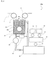
- FIG. 1 is a diagram illustrating a first example of a configuration of a surface treatment line according to the present embodiment.
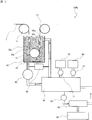
- FIG. 2 is a diagram illustrating a second example of the configuration of the surface treatment line according to the present embodiment.
- FIG. 3 is a diagram illustrating a third example of the configuration of the surface treatment line according to the present embodiment.
- FIG. 1 is a diagram showing a configuration of a surface treatment line 100 used in the manufacturing method of the present embodiment.
- the surface treatment line 100 of the present embodiment is a line for producing a surface-treated steel sheet formed by forming an oxygen compound film containing Zr (Zr oxygen compound film) on the substrate 1, as shown in FIG.
- the electrolytic treatment tank 30 and the circulation tank 50 are filled with an electrolytic treatment liquid 31 containing Zr ions and F ions. 1 is circulated between the electrolytic treatment tank 30 and the circulation tank 50 in the direction of the arrow shown in FIG.
- the conductor rolls 11 and 13 are energized by being electrically connected to an external power source (not shown), respectively, and can be energized while transporting the substrate 1.
- the anodes 20a to 20d are also electrically connected to each other by being electrically connected to the external power source, and function as electrodes when the base material 1 is subjected to electrolytic treatment.
- the power is supplied from the power supply via the conductor rolls 11 and 13 that are energized.
- the substrate 1 is continuously subjected to electrolytic treatment, and a Zr oxygen compound film is formed on the substrate 1.
- the substrate 1 may be anything as long as it is an iron-based substrate.
- a steel plate provided with a plating layer containing Cu, Al, etc. can be used in the form of a steel strip.
- the electrolytic treatment tank 30 is a treatment tank that is filled with an electrolytic treatment liquid 31 and forms a Zr oxygen compound film on the substrate 1 by electrolytic treatment.
- the base material 1 is sent into the electrolytic treatment tank 30 by the conductor roll 11, and the electrolytic treatment liquid 31 filled in the electrolytic treatment tank 30 is compared with the base material 1. Electrolysis is performed by the action of the anodes 20a to 20d.
- the measuring device 40 is provided in the flow path of the electrolytic treatment liquid 31 between the pump 60 and the circulation tank 50, and measures the free F ion concentration of the electrolytic treatment liquid 31.
- the pH of the electrolytic treatment liquid 31 is measured. Equipped with a pH meter and the like.
- the circulation tank 50 is filled with the electrolytic treatment liquid 31 similarly to the electrolytic treatment tank 30, and the electrolytic treatment liquid 31 can be supplied to the electrolytic treatment tank 30 by the pump 60.
- the circulation tank 50 is connected to the first replenishing liquid tank 70 and the second replenishing liquid tank 80, respectively.
- the first replenishing liquid described later from the first replenishing liquid tank 70 and the second replenishing liquid tank 80 to be described later.
- the second replenisher can be supplied.
- the first replenishing liquid tank 70 has therein a first replenishing liquid that is an aqueous solution in which the zirconium fluoride compound (A) is dissolved, and this first replenishing liquid is obtained by a pump 71 shown in FIG.
- the electrolytic treatment liquid 31 in the circulation tank 50 can be replenished at the timing of
- the second replenishing liquid tank 80 has a second replenishing liquid that is an aqueous solution in which the fluorine-free zirconium compound (B) is dissolved, and this second replenishing liquid is supplied by a pump 81 shown in FIG.
- the electrolytic treatment liquid 31 in the circulation tank 50 can be replenished at a desired timing.
- the first replenishment liquid containing the zirconium fluoride compound (A) from the first replenisher liquid tank 70 and the second replenisher liquid tank 80 with respect to the electrolytic treatment liquid 31 in the circulation tank 50, and fluorine Zr ion concentration and free F ion concentration can be adjusted for the electrolytic treatment liquid 31 circulating in the electrolytic treatment tank 30 and the circulation tank 50 by replenishing the second replenishment liquid containing the non-containing zirconium compound (B). It has become.
- the electrolytic treatment is performed in the electrolytic treatment liquid 31 of the electrolytic treatment tank 30, and the hydroxyl group generated by electrolysis on the substrate 1 and the fluorine of the zirconium fluoride compound are generated.
- a Zr oxygen compound film deposited by replacement is continuously formed.
- Zr ions in the electrolytic treatment liquid 31 are consumed as precipitated as Zr oxygen compounds, and the Zr ion concentration decreases. Go.
- the electrolytic treatment liquid 31 is fluorinated from the first replenishment liquid tank 70 and the second replenishment liquid tank 80 described above.
- Zr ions are replenished to the electrolytic treatment liquid 31, and the electrolytic treatment is performed.
- the Zr ion concentration in the liquid 31 is maintained.
- the Zr ions are consumed in the electrolytic treatment liquid 31, so that the F ions that have formed complex ions with the Zr ions are free F. As a result, the free F ion concentration in the electrolytic treatment liquid 31 increases.
- the free F ions in the electrolytic treatment liquid 31 act as a complexing agent that dissolves the Zr compound in the electrolytic treatment liquid 31 by forming complex ions with Zr ions, and therefore have a concentration above a certain level.
- the concentration increases too much, the base material 1 is excessively etched by free F ions, so that unnecessary Fe ions are eluted from the base material 1.
- the base material 1 Due to the excessive etching, the formability of the Zr oxygen compound film on the substrate 1 tends to be lowered.
- the supply amount of the first replenisher solution in which the fluorine-containing zirconium fluoride compound (A) is dissolved and the second non-fluorine-containing zirconium compound (B) not containing fluorine are dissolved.
- the concentration of free F ions in the electrolytic treatment liquid 31 in addition to the concentration of Zr ions is in an appropriate range. Can be controlled.
- each of the anodes 20a to 20d is electrically connected to an external power source (not shown).
- an external power source not shown.
- this When this is energized and the electrolytic treatment is performed, it acts on the base material 1 as an oxidation electrode (electrode from which electrons are extracted).
- the conductor rolls 11 and 13 provided around the electrolytic treatment tank 30 are also energized by being electrically connected to the external power source, and the substrate 1 is transported while the substrate 1 is transported. Works as a conductor roll that can flow. Therefore, the substrate 1 is energized by the carrier rolls 11 and 13 and is sent to the electrolysis treatment tank 30 in the energized state, so that the electrolysis is performed by the action of the anodes 20a to 20d, and the Zr oxygen compound is formed on the substrate 1 Is formed.
- the anodes 20a to 20d may be anything as long as they do not dissolve in the electrolytic treatment liquid 31 during the electrolytic treatment. However, iridium oxide or It is preferable to use a titanium plate coated with platinum.
- the electrolytic treatment liquid 31 contains Zr ions for forming a Zr oxygen compound film on the substrate 1 in a concentration range of 3,000 to 10,000 ppm by weight, F ions, and a pH of 2 It is an aqueous solution of 0.0 to 4.0.
- the electrolytic treatment liquid 31 is circulated in the electrolytic treatment tank 30 and the circulation tank 50 by the pump 60 in the direction of the arrow shown in FIG. Specifically, a pipe serving as a flow path for the electrolytic treatment liquid 31 is connected to the bottom and top of the electrolytic treatment tank 30, and the electrolytic treatment liquid 31 in the circulation tank 50 is fed by the pump 60 to the electrolytic treatment tank 30.
- the electrolytic treatment liquid 31 in the electrolytic treatment tank 30 is discharged from the pipe connected to the upper part of the electrolytic treatment tank 30 and supplied to the circulation tank 50.
- a part of the electrolytic treatment liquid 31 flowing from the pump 60 to the electrolytic treatment tank 30 is appropriately collected by the measuring device 40 and the free F ion concentration, pH, and the like are measured. .
- the electrolytic treatment liquid 31 circulates in the electrolytic treatment tank 30 and the circulation tank 50 as described above, and the first replenishment liquid tank 70 and the above-described electrolytic treatment liquid 31 in the circulation tank 50 are used.
- the first replenisher and the second replenisher are replenished from the second replenisher tank 80.
- the electrolytic treatment liquid 31 before receiving the replenishment of the first replenisher and the second replenisher is a Zr compound for forming Zr ions such as zirconium ammonium fluoride, potassium zirconium fluoride, Basic zirconium carbonates such as ammonium zirconium carbonate, zirconium oxynitrate, zirconium oxyacetate and the like can be used alone or in combination of two or more.
- Zr compound for forming Zr ions such as zirconium ammonium fluoride, potassium zirconium fluoride, Basic zirconium carbonates such as ammonium zirconium carbonate, zirconium oxynitrate, zirconium oxyacetate and the like can be used alone or in combination of two or more.
- a Zr compound that forms Zr ions of the electrolytic treatment liquid 31 from the viewpoint of easy management of components in the electrolytic treatment liquid 31, zirconium ammonium fluoride, zirconium oxynitrate It is preferable to use either or both. That is, when the electrolytic treatment is performed in the electrolytic treatment tank 30, an aqueous nitric acid solution, aqueous ammonia, or the like is appropriately added as a pH adjuster to the electrolytic treatment liquid 31.
- the counter ion of the Zr ion derived from the Zr compound is the same as the nitrate ion or ammonium ion derived from the pH adjuster. Therefore, management of the components in the electrolytic treatment liquid 31 is facilitated.
- the Zr ion concentration in the electrolytic treatment liquid 31 may be 3,000 to 10,000 ppm by weight, preferably 3,000 to 8,000 ppm by weight, and more preferably 4,000 to 8,000. 000 ppm by weight.
- the Zr concentration in the electrolytic treatment liquid 31 is less than 3,000 ppm by weight, the formation rate of the Zr oxygen compound film on the substrate 1 is reduced, so that the Zr oxygen compound film formed on the steel plate.
- an additional electrolytic treatment tank 30 and a line speed (base material) of the surface treatment line 100 1 transport speed) must be reduced, and the production efficiency of the surface-treated steel sheet will be reduced.
- the Zr concentration in the electrolytic treatment liquid 31 is more than 8,000 ppm by weight, the surface of the substrate 1 is easily etched by the Zr ions in the electrolytic treatment liquid 31, and the formation rate of the Zr oxygen compound film is increased. Decreases, and the production efficiency of the surface-treated steel sheet decreases.
- the electrolytic treatment liquid 31 contains F ions in addition to the Zr ions described above, and the F ions act as a complexing agent for increasing the solubility of Zr ions in the liquid.
- the fluoride for forming F ions is not particularly limited, but a Zr compound containing fluorine such as ammonium zirconium fluoride may be used as the above-mentioned Zr compound, or ammonium fluoride, aluminum fluoride, fluoride. Titanium, sodium fluoride, hydrofluoric acid, calcium fluoride, hexafluorosilicic acid, sodium hexafluorosilicate, and the like may be used, and among these, zirconium ammonium fluoride is preferable.
- a Zr compound containing fluorine such as ammonium zirconium fluoride
- titanium, sodium fluoride, hydrofluoric acid, calcium fluoride, hexafluorosilicic acid, sodium hexafluorosilicate, and the like may be used, and among these, zirconium ammonium fluoride is preferable.
- F ions include F ions forming complex ions with Zr ions and free F ions.
- the concentration of free F ions in the electrolytic treatment solution 31 is preferably 10 to 150 ppm by weight, more preferably 10 to 100 ppm by weight. If the concentration of free F ions in the electrolytic treatment liquid 31 is less than 10 ppm by weight, the solubility of Zr ions in the electrolytic treatment liquid 31 tends to decrease, and precipitation of Zr compounds tends to occur. On the other hand, if the concentration of free F ions in the electrolytic treatment liquid 31 exceeds 150 ppm by weight, the substrate 1 is excessively etched, so that Zr oxygen corresponding to the electrolytic treatment conditions (current density, treatment time, etc.). The deposition efficiency of the compound tends to be reduced, and further, unnecessary Fe ions and the like accumulate in the electrolytic treatment liquid 31 due to the etching of the base material 1.
- the concentration of free F ions in the electrolytic treatment liquid 31 is obtained by measuring the electrolytic treatment liquid 31 circulating in the electrolytic treatment tank 30 and the circulation tank 50 as shown in FIG. Can be measured by an ion electrode method using an F ion electrode using an ion measuring device provided in the measuring device 40. Since the concentration of free F ions fluctuates due to the influence of the pH and temperature of the electrolytic treatment solution 31, the measurement of the concentration of free F ions is constant, for example, at a pH of 3.0 and a temperature of 25 ° C. It is preferable to carry out under the conditions. Alternatively, the concentration of free F ions is converted in advance to the value measured at various conditions under the conditions of pH 3.0 and temperature 25 ° C. by the ion electrode method using the F ion electrode described above. A map may be prepared and the value of the actually measured free F ion concentration may be obtained by conversion using the map.
- the concentration of nitrate ions in the electrolytic treatment liquid 31 is preferably 0.45 or more in terms of the weight concentration ratio of Zr ions to nitrate ions, “weight concentration of Zr ions / weight concentration of nitrate ions”. If the weight concentration of Zr ions in the electrolytic treatment liquid 31 / the weight concentration of nitrate ions is less than 0.45, the substrate 1 is excessively etched, so that the conditions for the electrolytic treatment (current density, treatment time, etc.) Accordingly, the deposition efficiency of the Zr oxygen compound tends to decrease, and further, unnecessary Fe ions and the like are accumulated in the electrolytic treatment liquid 31 due to the etching of the base material 1.
- the electrolytic treatment liquid 31 as a complexing agent for enhancing the solubility of Zr ions, cyanide or the like may be further used in addition to the above-described fluoride.
- the electrolytic treatment liquid 31 includes calcium ions, lactate ions, chloride ions, sulfate ions, sodium ions, magnesium ions as long as the formation of the Zr oxygen compound film is not hindered.
- An electrolyte such as nitrate ion or ammonium ion may be added.
- ions similar to ions derived from the pH adjuster, that is, nitrate ions or ammonium ions are used from the viewpoint of easy management of components in the electrolytic treatment solution 31. preferable.
- the electrolytic treatment liquid 31 may include at least one or more of organic additives such as polyitaconic acid, polyacrylic acid, citric acid, lactic acid, tartaric acid, and glycolic acid, and resin additives such as phenol resin. Good.
- organic additives such as polyitaconic acid, polyacrylic acid, citric acid, lactic acid, tartaric acid, and glycolic acid
- resin additives such as phenol resin. Good.
- an organic resin layer such as a paint or film is formed on the Zr oxygen compound film by adding such an organic acid or resin additive to the electrolytic treatment liquid 31, the Zr oxygen compound film and the organic resin layer are formed. Can be further improved.
- the base material 1 is subjected to electrolytic processing as follows, and a Zr oxygen compound film is formed on the base material 1.
- the base material 1 is changed in the traveling direction by the sink roll 12, and faces the anodes 20c and 20d in the electrolytic treatment liquid 31, respectively.
- the electrolytic treatment is again performed, and a Zr oxygen compound film is further formed on the substrate 1.
- the substrate 1 is pulled up from the electrolytic treatment tank 30 by the conductor roll 13.
- the electrolytic treatment for the base material 1 by the electrolytic treatment tank 30 is performed in this manner.
- the amount of the Zr oxygen compound film may be 30 mg / m 2 or more in terms of the weight of Zr contained in the Zr oxygen compound film, preferably 50 mg / m 2 or more, more preferably 70 mg / m 2 or more.
- the coating amount of the Zr oxygen compound film is less than 30 mg / m 2 in terms of the weight of Zr
- the surface-treated steel sheet obtained by forming the Zr oxygen compound film on the substrate 1 is used as a two-piece can such as a DR can.
- the can side wall is thinly extended, so the base material is exposed at a part of the can side wall, and when the food or drink is filled in the can, it tends to become a starting point of corrosion and the corrosion resistance decreases. It tends to end up.
- the upper limit of the Zr amount of the Zr oxygen compound film is not particularly limited, but is preferably 300 mg / m 2 or less.
- the amount of Zr is excessively increased, when an organic resin layer is formed on the Zr oxygen compound film formed on the substrate 1, the work adhesion between the Zr oxygen compound film and the organic resin layer tends to be reduced. is there.
- the current density during the electrolytic treatment is not particularly limited, but is preferably 1 to 30 A / dm 2 . By setting the current density within the above range, a Zr oxygen compound film can be satisfactorily formed on the substrate 1.
- the rate of formation of the Zr oxygen compound film during the electrolytic treatment is not particularly limited, but the Zr amount per unit area and unit time is preferably 70 mg / (m 2 ⁇ sec) or more.
- the formation rate of the Zr oxygen compound film is less than 70 mg / (m 2 ⁇ sec)
- an electrolytic treatment tank 30 is added, or the surface treatment line 100 It is necessary to reduce the line speed, and the production efficiency of the surface-treated steel sheet is lowered.
- the electrolytic treatment is performed as described above. Next, a method for supplying the first supply liquid and the second supply liquid to the electrolytic treatment liquid 31 used in the surface treatment line 100 will be described.
- the first replenishment containing the zirconium fluoride compound (A) from the first replenisher liquid tank 70 to the electrolytic treatment liquid 31 in the circulation tank 50 by the pump 71.
- the second replenishment containing the fluorine-free zirconium compound (B) is replenished by the pump 81 from the second replenisher tank 80.
- the zirconium fluoride compound (A) contained in the first replenishment is not particularly limited, and for example, zirconium fluoride ammonium, hydrofluoric zirconate or the like can be used.
- the content of the zirconium fluoride compound (A) in the first replenisher may be 10,000-250,000 ppm by weight, preferably 25,000-100,000 in terms of the Zr ion concentration in the first replenisher. 000 ppm by weight.
- the pH of the first replenisher may be 5 or less, more preferably 3 or less.
- an aqueous nitric acid solution or hydrofluoric acid is added to the first replenishing solution in order to improve the solubility of the zirconium fluoride compound (A). Also good.
- the fluorine-free zirconium compound (B) contained in the second replenisher is not particularly limited, and for example, basic zirconium carbonate such as zirconium ammonium carbonate, zirconium oxynitrate, zirconium oxyacetate and the like can be used.
- the content of the fluorine-free zirconium compound (B) in the second replenishing solution may be 10,000 to 200,000 ppm by weight in terms of the Zr ion concentration in the second replenishing solution, but is preferably 100,000 to 200. 1,000 ppm by weight.
- the pH of the second replenisher may be 5 or less, more preferably 2 or less.
- a nitric acid aqueous solution or the like may be added to the second replenishing solution in order to improve the solubility of the fluorine-free zirconium compound (B).
- the first replenisher solution in which the fluorine-containing zirconium fluoride compound (A) is dissolved in the electrolytic treatment solution 31 and the fluorine-free zirconium compound (B) that does not contain fluorine are dissolved.
- the Zr ion concentration, free F ion or nitrate ion concentration in the electrolytic treatment liquid 31 during the electrolytic treatment in the surface treatment line 100 is appropriately adjusted. can do.
- the electrolytic treatment is continuously performed, so that the Zr ions in the electrolytic treatment liquid 31 are consumed as precipitated as a Zr oxygen compound, and the Zr ion concentration is reduced. The formability of the Zr oxygen compound film on the top is lowered.
- Zr ions are consumed, so that F ions that have formed complex ions with Zr ions become free F ions, and the concentration of free F ions in the electrolytic treatment liquid 31 increases. As a result, the substrate 1 is excessively etched, and the formability of the Zr oxygen compound film on the substrate 1 is further reduced.
- a method of supplying a replenisher solution in which a fluorine-free zirconium compound not containing fluorine is dissolved to the electrolytic treatment solution 31 is also conceivable, but in this method, Zr ions in the electrolytic treatment solution 31 are considered.
- the concentration of free F ions in the electrolytic treatment liquid 31 is excessively lowered by supplying the replenishing solution, but F ions that form complex ions with Zr ions in the electrolytic treatment liquid 31 can be adjusted.
- the amount of ions decreases and the solubility of Zr ions decreases, so that the formability of the Zr oxygen compound film on the substrate 1 decreases.
- a method of supplying a replenisher solution containing both such a zirconium fluoride compound and a fluorine-free zirconium compound to the electrolytic treatment solution 31 is also conceivable, but even if only such a replenisher solution is used, There is also a problem that it is difficult to simultaneously adjust the Zr ion concentration and the free F ion concentration in the electrolytic treatment liquid 31 to appropriate values during the electrolytic treatment.
- the first replenisher liquid in which the fluorine-containing zirconium compound (A) containing fluorine is dissolved and the second replenishment liquid in which the fluorine-free zirconium compound (B) containing no fluorine is dissolved The replenisher is supplied to the electrolytic treatment liquid 31, and the electrolytic treatment is performed on the surface treatment line 100 by adjusting and balancing the supply amounts of the first replenisher and the second replenisher.
- the Zr ion concentration and free F ion concentration in the electrolytic treatment liquid 31 during the process can be appropriately controlled, thereby improving the stability of the electrolytic treatment liquid 31 and obtaining Zr oxygen obtained by the electrolytic treatment.
- the stability of the compound film is also improved, and a Zr oxygen compound film can be formed continuously and stably on the substrate 1.
- a treatment liquid containing Zr ions at a high concentration of 3,000 to 10,000 ppm by weight is used as the electrolytic treatment liquid 31, and the first replenishing liquid and the electrolytic treatment liquid 31 are used.
- the Zr ion concentration in the electrolytic treatment liquid 31 can be controlled within the above range by replenishing the second replenisher, the line speed of the surface treatment line 100 (the conveyance speed of the substrate 1) is increased.
- the Zr oxygen compound film can be appropriately formed on the substrate 1, and the production efficiency of the surface-treated steel sheet can be improved.
- the Zr ion concentrations of the first replenisher and the second replenisher may be the above-described values, but the Zr ion concentration of the mixed solution of the first replenisher and the second replenisher, that is, the electrolytic treatment liquid 31.
- the Zr ion concentration of the mixed solution may be adjusted to be a value close to the Zr ion concentration in the electrolytic treatment liquid 31 before replenishment. preferable.
- zirconium fluoride compound (A) used for the first replenishing liquid and the fluorine-free zirconium compound (B) used for the second replenishing liquid electrolysis before replenishing the first replenishing liquid and the second replenishing liquid is performed.
- the same Zr compound contained in the treatment liquid 31 is preferably used.
- zirconium ammonium fluoride and zirconium oxynitrate were used as the Zr compound for forming Zr ions.
- zirconium ammonium fluoride as the zirconium fluoride compound (A) of the first replenisher
- zirconium oxynitrate is used as the fluorine-free zirconium compound (B) of the second replenisher.
- the solubility of the Zr compound replenished with the 1st replenishing liquid and the 2nd replenishing liquid can be improved.
- the replenishment amounts of the first replenisher and the second replenisher can be set based on the information on the free F ion concentration measured by the measuring device 40.
- the measuring device 40 can measure the free F ion concentration and the like of the electrolytic treatment liquid 31, so that while the electrolytic treatment is performed on the surface treatment line 100, the measurement device 40 Based on the information on the free F ion concentration measured by 40, the replenishment amounts of the first replenisher and the second replenisher can be set.
- FIG. 1 the example in which the measurement device 40 is installed between the pump 60 and the circulation tank 50 is shown, but the installation position of the measurement device 40 is not particularly limited. It may be installed directly at the position where the electrolytic treatment liquid 31 in the circulation tank 50 can be measured.
- the replenishment amounts of the first replenisher and the second replenisher may be set in advance based on the recorded decrease rates of the Zr ions and free F ions.
- the replenishment amounts of the first replenisher and the second replenisher are determined by taking out the electrolytic treatment liquid 31 when the electrolytic treatment is performed in the surface treatment line 100 (electrolytic treatment with the electrolytic treatment liquid 31 attached to the substrate 1). It is set in consideration of the amount of decrease caused by evaporation). For example, when the reduction amount of the electrolytic treatment liquid 31 is an amount of about 0.1 to 1.5 L / min, the total of the supplementary amounts of the first supplementary liquid and the second supplementary liquid is the electrolytic treatment liquid 31. Adjust to be the same as the amount of decrease. At this time, the Zr ion concentration and the free F ion concentration in the first replenisher and the second replenisher are adjusted in advance so that the decrease amount of the electrolytic treatment liquid 31 and the replenisher amount are approximately the same. To.
- the first replenisher can be replenished by extruding the first replenisher from the first replenisher tank 70 by the pump 71.
- the second replenisher can be replenished by extruding the second replenisher from the second replenisher tank 80 by the pump 81.
- Such replenishment of the first replenisher and the second replenisher is possible.
- the electrolytic treatment is being performed in the surface treatment line 100, it is continuously performed so that the Zr ion concentration and the free F ion concentration in the electrolytic treatment liquid 31 do not substantially vary.
- the replenishment of the first replenisher and the second replenisher may be performed continuously using a metering pump or the like as the pumps 71 and 81.
- the Zr ion concentration in the electrolytic treatment liquid 31 may be increased. While the fluctuation is within ⁇ 10% and the fluctuation of the free F ion concentration is controlled to be within ⁇ 50%, it may be performed intermittently, but the stability of the electrolytic treatment solution 31 and the formation of the Zr oxygen compound film It is preferable to carry out continuously from the viewpoint that the stability of the can be improved.
- a pH adjusting agent such as an aqueous nitric acid solution or aqueous ammonia to the electrolytic treatment solution 31.
- the pH of the electrolytic treatment solution 31 may be 2.0 to 4.0 as described above, but is preferably 2.5 to 4.0. By controlling the pH of the electrolytic treatment liquid 31 within the above range, the electrolytic treatment liquid 31 is excellent in the stability of the components in the aqueous solution and the deposition efficiency of the Zr oxygen compound.
- FIG. 1 As a form of replenishment of the first replenishing liquid and the second replenishing liquid, as shown in FIG. 1, it is assumed that the circulation tank 50 is replenished directly from the first replenishing liquid tank 70 and the second replenishing liquid tank 80.
- a mix tank that is a tank for mixing the first supply liquid and the second supply liquid from the first supply liquid tank 70 and the second supply liquid tank 80. It is good also as a form which replenishes the circulation tank 50 with the pump 91 through 90.
- FIG. Thereby, it becomes easy to mix the 1st replenishment liquid and the 2nd replenishment liquid, and the electrolytic treatment liquid 31, and it becomes possible to perform replenishment stably.
- the electrolytic treatment liquid 31 in the circulation tank 50 is obtained.
- the free F ions in the electrolytic treatment liquid 31 act as a complexing agent, and the Zr compound in the mixed solution can be dissolved.
- the pH of the first replenisher and the second replenisher is adjusted using a pH adjuster in order to suppress the precipitation of the Zr compound. May be adjusted as appropriate.
- the electrolytic treatment liquid 31 while circulating the electrolytic treatment liquid 31 between the electrolytic treatment tank 30 and the circulation tank 50, a part of the electrolytic treatment liquid 31 in the circulation tank 50 is obtained.
- the Zr ions are concentrated and excessively present by flowing into the reverse osmosis membrane treatment device 93 by the pump 92 and performing the reverse osmosis membrane treatment by the reverse osmosis membrane provided in the reverse osmosis membrane treatment device 93.
- the permeated liquid containing a component that inhibits the formation of the film is separated, and the permeated liquid is discarded by sending it to the permeated liquid tank 94. Only the concentrated liquid is returned to the circulation tank 50, and the electrolytic treatment tank 30 is disposed.
- the electrolytic treatment liquid 31 may be mixed with the electrolytic treatment liquid 31 circulating between the water and the circulation tank 50. Thereby, a part of the non-film forming component that may inhibit the formation of the Zr oxygen compound film in the electrolytic treatment liquid 31 can be separated and removed as a permeate by the reverse osmosis membrane treatment apparatus 93. If the nitrate ions contained in the replenisher or the pH adjuster are also accumulated in the electrolytic treatment liquid 31 by this removal, the substrate 1 is excessively etched as in the case where the free F ion concentration is increased. The problem that the formability of the Zr oxygen compound film on the substrate 1 is further lowered can be solved.
- a method for performing reverse osmosis membrane treatment by the reverse osmosis membrane treatment apparatus 93 in the surface treatment line 100b of the present embodiment will be described in detail.
- the electrolytic treatment liquid 31 circulates between the electrolytic treatment tank 30 and the circulation tank 50 as described above. At this time, the electrolytic treatment liquid 31 in the circulation tank 50 is used. A part of this is sent to the reverse osmosis membrane treatment device 93 by the pump 92, and the reverse osmosis membrane treatment device 93 performs the reverse osmosis membrane treatment.
- the electrolytic treatment liquid 31 extruded at a pressure equal to or higher than the osmotic pressure by the pump 92 permeates through the reverse osmosis membrane provided in the reverse osmosis membrane treatment device 93, so that the reverse osmosis membrane treatment is performed.
- the electrolytic treatment liquid 31 is separated into a concentrated liquid obtained by concentrating Zr ions necessary for the formation of the Zr oxygen compound film, and a permeated liquid containing a component that inhibits the formation of the film due to its excessive presence.
- the reverse osmosis membrane treatment device 93 returns the concentrated solution separated by the reverse osmosis membrane treatment to the circulation tank 50, while discarding the permeate separated by the reverse osmosis membrane treatment by sending it to the permeate tank 94.
- membrane when it exists excessively from the electrolytic treatment liquid 31 can be removed effectively, and formation of a Zr oxygen compound film
- Zr ions in the electrolytic treatment solution 31 can be reused, which is advantageous in terms of cost.
- nitrate ions that are counter ions of Zr ions are used in the electrolytic treatment liquid 31.
- ammonium ions are present as a component that inhibits the formation of the film due to the presence of the above-described excess.
- membrane when it exists in excess like this is hardly consumed even when a Zr oxygen compound film
- the concentration of the component that inhibits the formation increases with respect to the concentration of Zr ions consumed as the Zr oxygen compound film.
- the concentration of nitrate ions, which are components that inhibit the formation of the film due to the excessive presence thereof, in the electrolytic treatment solution 31 increases excessively with respect to Zr ions, the substrate 1 is excessively contained in the electrolytic treatment solution 31. As a result, it becomes difficult to form a Zr oxygen compound film on the substrate 1, and the formation of the Zr compound film tends to be inhibited.
- the electrolytic treatment liquid 31 contains a Zr oxygen compound film formed by the electrolytic treatment. While Zr ions are consumed one after another due to the formation, nitrate ions, ammonium ions, and the like, which are these counter ions and inhibit the formation of the film due to their excessive presence, are hardly consumed. As a result, the concentration of the component that inhibits the formation of the film due to the excessive presence thereof becomes larger than the concentration of Zr ions.
- the pH adjusting agent mentioned above and the electrolyte for improving the electrical conductivity of the electrolytic treatment liquid 31 are appropriately added to the electrolytic treatment liquid 31, nitrate ions and ammonium ions derived therefrom are excessive.
- the concentration of the component that inhibits the formation of the film increases when present in excess.
- the reverse osmosis membrane treatment apparatus 93 performs the reverse osmosis membrane treatment
- the treatment liquid 31 is separated into a permeate containing a large amount of components such as nitrate ions and ammonium ions that inhibit film formation, and a concentrate containing a large amount of Zr ions. While removing the concentrated liquid, the concentration of the component that inhibits the formation of the film due to the excessive presence of nitrate ions and ammonium ions in the electrolytic processing liquid 31 is reduced by returning the concentrated liquid to the electrolytic processing liquid 31. And the stability of the formation of the Zr oxygen compound film can be improved.
- the reverse osmosis membrane treatment apparatus 93 can appropriately separate the electrolytic treatment liquid 31 into the concentrated liquid and the permeated liquid described above by the reverse osmosis membrane provided inside.
- the reverse osmosis membrane in the reverse osmosis membrane treatment apparatus 93 preferably has a permeability of sodium ions and chloride ions when a sodium chloride aqueous solution having a concentration of 2.0 g / L is permeated. 60% by weight or more.
- the permeability of the reverse osmosis membrane is less than 60% by weight, Zr ions easily pass through the reverse osmosis membrane and are discarded as a permeate. The efficiency of will decrease.
- the commercially available reverse osmosis membrane (Brand name "NF membrane module PTW" (made by Polytex)) etc. can be used, for example.
- the shape of the reverse osmosis membrane treatment device 93 is not particularly limited, and for example, a shape in which a reverse osmosis membrane, a mesh spacer, and a permeate channel material are wound around a permeate water collection pipe can be used.
- the scale and filtration area of the reverse osmosis membrane treatment device 93 are not particularly limited, but depending on the concentration of the component that inhibits the formation of the film due to the excessive presence of nitrate ions, ammonium ions, etc. in the electrolytic treatment liquid 31, What is necessary is just to design suitably.
- the pressure when the reverse osmosis membrane treatment apparatus 93 performs the reverse osmosis membrane treatment is preferably 0.1 to 1. 0.0 MPa, more preferably 0.1 to 0.4 MPa. If the pressure during reverse osmosis membrane treatment is less than 0.1 MPa, separation may occur when the electrolytic treatment liquid 31 is separated into a permeate and a concentrated liquid. If present, the removal effect of components that inhibit the formation of the film tends to be reduced. If the pressure during the reverse osmosis membrane treatment exceeds 0.4 MPa, the pressure is too high, the reverse osmosis membrane treatment device 93 may be loaded, and the reverse osmosis membrane treatment device 93 may be damaged. is there.
- the amount of the permeate separated by the reverse osmosis membrane treatment changes depending on the pressure when performing the reverse osmosis membrane treatment, but if the amount of the permeate to be separated is too large, it exists in the electrolytic treatment liquid 31. As a result, the concentration change of each component increases, and the amount of Zr oxygen compound film formed by the electrolytic treatment tends to be uneven. On the other hand, if the amount of the permeated liquid to be separated is too small, the effect of removing components that inhibit the formation of the film due to the excessive presence of nitrate ions, ammonium ions and the like described above will be reduced.
- the reverse osmosis membrane treatment apparatus 93 can control the amount of permeate and concentrate separated by adjusting the pressure and filtration area when performing reverse osmosis membrane treatment.
- the change in the concentration of each component in the electrolytic treatment liquid 31 can be suppressed, and the formation amount of the Zr oxygen compound film can be made uniform.
- the electrolytic treatment liquid 31 supplied to the reverse osmosis membrane treatment device 93 is roughly filtered, Existing particulate impurities may be removed.
- the electrolytic treatment liquid 31 is roughly filtered by a coarse filtration device, whereby the life of the reverse osmosis membrane treatment device 93 can be extended, which is advantageous in terms of cost. become.
- a coarse filtration apparatus For example, a commercially available bag filter, a cartridge filter, an ultra filter (UF) etc. can be used individually or in combination.
- UF ultra filter
- the electrolytic treatment liquid 31 that has flowed from the electrolytic treatment tank 30 to the circulation tank 50 at a predetermined timing during the electrolytic treatment is measured by the measuring device 40.
- the rate (EC) was measured.
- the Zr ion concentration and the Fe ion concentration were measured by using an ICP emission spectrometer (ICPE-9000, manufactured by Shimadzu Corporation), and the total F ion concentration and nitrate ion concentration were measured by an ion chromatograph ( Nippon Dionex, DX-500), pH was measured using a pH meter (manufactured by Horiba Seisakusho), and conductivity was measured using a conductivity meter (manufactured by Nikko Hansen, CyberScan CON110).
- the electrolytic treatment liquid 31 that has flowed from the electrolytic treatment tank 30 to the circulation tank 50 at a predetermined timing during the electrolytic treatment is measured by the measuring device 40.
- the collected electrolytic treatment solution 31 was adjusted to pH 3.0 using a nitric acid aqueous solution or aqueous ammonia and the temperature was adjusted to 25 ° C., and then a portable ion meter (IM-32P (F-ion electrode: manufactured by Toa DKK Corporation) The free F ion concentration was measured by the ion electrode method using F-2010)).
- IM-32P F-ion electrode: manufactured by Toa DKK Corporation
- the organic resin-coated steel sheet obtained by forming an organic resin layer on one surface of the surface-treated steel sheet was evaluated for cross-cut corrosion resistance as follows. First, on the surface of the organic resin-coated steel sheet on which the organic resin layer was formed, a 4 cm long cross-cut wound was made using a cutter so as to reach the base steel sheet. Next, the organic resin-coated steel sheet with the cross cut wound was immersed in a commercially available coffee beverage (Ajinomoto General Foods, “Blendy Bottle Coffee Low Sugar”), temperature: 37 ° C., retention period: 1 month The condition was maintained. In this case, the coffee beverage was appropriately replaced with a new one so that mold did not occur in the coffee beverage.
- a commercially available coffee beverage Ajinomoto General Foods, “Blendy Bottle Coffee Low Sugar”
- the cross-cut corrosion resistance was evaluated by determining the range of the discolored portion of the organic resin-coated steel sheet in the cross-cut portion according to the following criteria.
- the cross-cut corrosion resistance indicates the adhesion of the organic resin layer in the organic resin-coated steel sheet, and the organic resin-coated steel sheet having three or more points has liquid in the scratched part even when the surface is scratched. It can prevent intrusion, has excellent corrosion resistance, and can be used particularly suitably for applications such as metal cans. Further, the cross-cut corrosion resistance was performed only for Reference Examples 6 to 9 among Examples, Comparative Examples and Reference Examples described later.
- Discolored portion has a radius of less than 0.5 mm from the cross-cut portion 4 points: Discolored portion has a radius of 0.5 mm or more and less than 1.0 mm from the cross-cut portion 3 points: Discolored portion has a radius of 1 from the cross-cut portion 0.0 mm or more and less than 2.0 mm 2 points: Discolored portion has a radius of 2.0 mm or more and less than 3.0 mm from the crosscut portion 1 point: Discolored portion has a radius of 3.0 mm or more from the crosscut portion
- Example 1 A low carbon cold-rolled steel sheet (thickness 0.2 mm, width 1,000 mm) was prepared as an original sheet.
- the prepared steel sheet was electrolytically degreased in an alkaline aqueous solution in which a commercially available degreasing agent (Nippon Quaker Chemical Co., Ltd., Formula 618-TK2) was dissolved, then washed with water, and then immersed in a sulfuric acid aqueous solution for pickling. Then, using the surface treatment line 100 shown in FIG. 1, electrolytic treatment was performed under the following conditions to form a Zr oxygen compound film on the steel plate. Next, the steel sheet on which the Zr oxygen compound film was formed was washed with water and dried to obtain a surface-treated steel sheet.
- a commercially available degreasing agent Naippon Quaker Chemical Co., Ltd., Formula 618-TK2
- Composition of electrolytic treatment solution 31 Zr ion concentration obtained by dissolving zirconium fluoride ammonium as a Zr compound and further adding a nitric acid aqueous solution, total F ion concentration 7,000 ppm by weight, nitrate ion concentration 2,000 ppm by weight aqueous solution pH of electrolytic treatment solution 31: 3.0 (pH adjustment with ammonia)
- Electrolytic treatment liquid 31 temperature 40 ° C.
- Current density in steel sheet 10 A / dm 3
- Energizing time 0.6 seconds Stopping time: 0.1 seconds
- the energization time mentioned above is the time during which the steel plate passes the vicinity of the anodes 20a and 20b or the vicinity of the anodes 20c and 20d in the surface treatment line 100, that is, the steel plate is subjected to the electrolytic treatment. Shows time.
- the stop time indicates the time from when the steel plate is subjected to the electrolytic treatment by the anodes 20a and 20b until the next electrolytic treatment by the anodes 20c and 20d is performed.
- the surface-treated steel sheet was continuously produced until the treatment area for the electrolytic treatment reached 40,000 m 2 .
- the first replenisher liquid 70 is supplied from the first replenisher liquid tank 70 to the second replenisher liquid tank 80 from the second replenisher liquid tank 80 under the following conditions.
- Each replenisher was replenished continuously.
- an aqueous nitric acid solution or aqueous ammonia was appropriately added to the electrolytic treatment liquid 31 so that the pH of the electrolytic treatment liquid 31 was around 3.0.
- First replenisher Aqueous solution in which ammonium zirconium fluoride is dissolved so as to have a Zr ion concentration of 50,000 ppm by weight
- Replenisher of the first replenisher 0.8 L / min
- Second replenisher Aqueous solution in which zirconium oxynitrate is dissolved at a Zr ion concentration of 150,000 ppm by weight
- Second replenisher replenisher 0.1 L / min
- the treatment area where the electrolytic treatment was performed was 4,500 m 2 , 7,000 m 2 , 20,000 m 2 , 40,000 m 2 .
- the Zr ion concentration, total F ion concentration, free F ion concentration, nitrate ion concentration, pH, and conductivity (EC) were measured according to the methods described above.
- the amount of Zr in a Zr oxygen compound film was measured according to the method mentioned above. The results are shown in Table 1.
- Example 2 A surface-treated steel sheet was prepared and evaluated in the same manner as in Example 1 except that the replenishment amount of the first replenisher was changed to 1.1 L / min and the replenisher of the second replenisher was changed to 0.09 L / min. Went. The results are shown in Table 2.
- the production of the surface-treated steel sheet was continuously performed until the treatment area of the electrolytic treatment reached 56,000 m 2, and the treatment area subjected to the electrolytic treatment was 6, as shown in Table 2. 000m 2, 16,000m 2, 42,000m 2 , were each evaluated by the timing became 56,000m 2.
- Comparative Example 1 The same as Example 1 except that only the first replenisher was supplied at a replenishment rate of 1.3 L / min without replenishing the second replenisher to the electrolytic treatment liquid 31 in the circulation tank 50. Then, a surface-treated steel sheet was produced and evaluated in the same manner. The results are shown in Table 3. In Comparative Example 1, the production of the surface-treated steel sheet was continuously performed until the treatment area of the electrolytic treatment reached 36,000 m 2, and the treatment area subjected to the electrolytic treatment was 8, as shown in Table 3. 200m 2, were each evaluated by the timing became 36,000m 2.
- Comparative Example 2 A first replenisher is replenished to the electrolytic treatment liquid 31 in the circulation tank 50 at a replenishment amount of 1.1 L / min, and instead of the second replenisher, powdered zirconium carbonate is used as a solid replenisher for 1 minute.
- a surface-treated steel sheet was produced in the same manner as in Example 1 except that 35 g per hit was replenished, and evaluated in the same manner. The results are shown in Table 4.
- the production of the surface-treated steel sheet was continuously performed until the treatment area of the electrolytic treatment reached 25,000 m 2, and the treatment area subjected to the electrolytic treatment was 16, as shown in Table 4, 000m 2, were each evaluated by the timing became 25,000m 2.
- Comparative Example 3 The first replenisher and the second replenisher are not continuously replenished, but are performed only once at the timing when the electrolytic treatment area reaches 10,000 m 2. Similarly, a surface-treated steel sheet was produced and evaluated in the same manner. The results are shown in Table 5. The replenishing amounts of the first replenishing solution and the second replenishing solution were such that the Zr ion concentration and free F ion concentration in the electrolytic treatment solution 31 were close to the values at the start of the electrolytic treatment. In Comparative Example 3, the preparation of the surface-treated steel sheet was continuously performed until the treatment area of the electrolytic treatment reached 20,000 m 2 . 000m 2, were each evaluated by the timing became 20,000m 2. Further, in Comparative Example 3, as shown in Table 5, the presence or absence of precipitation of the compound in the electrolytic treatment liquid 31 was confirmed by observing the appearance of the electrolytic treatment liquid 31.
- the first replenisher solution in which the zirconium fluoride compound (A) was dissolved and the second replenisher solution in which the fluorine-free zirconium compound (B) was dissolved were continuously replenished.
- the Zr ion concentration in the electrolytic treatment solution 31 was 3,000 to 10,000 ppm by weight
- the Zr ion concentration and the free F ion concentration in the electrolytic treatment solution were almost dependent on the treatment area of the electrolytic treatment. It was stable and stable.
- the Zr amount of the Zr oxygen compound film can be set to a sufficient amount of 125 to 135 mg / m 2 and the Zr oxygen compound calculated based on the Zr amount of the formed Zr oxygen compound film is used.
- the compound formation rate was as high as 70 mg / (m 2 ⁇ sec) or higher, and the Zr oxygen compound formation was excellent.
- the free F ion concentration was stable regardless of the treatment area of the electrolytic treatment, but a precipitate was seen at the bottom of the electrolytic treatment tank 30 and the circulation tank 50, and a part of the replenished zirconium carbonate was part of the electrolytic treatment liquid. 31 was found not to be dissolved. Further, as shown in Table 5, in Comparative Example 3 in which the first replenisher and the second replenisher were not continuously replenished, the free F ion concentration in the electrolytic treatment liquid 31 was such that the treatment area of the electrolytic treatment was increased. Increased, and the formation rate of the Zr oxygen compound calculated based on the Zr amount of the formed Zr oxygen compound film was as low as 40 mg / (m 2 ⁇ sec).
- Example 3 A low carbon cold-rolled steel sheet (thickness 0.2 mm, width 200 mm) was prepared as an original sheet.
- the prepared steel sheet was electrolytically degreased in an alkaline aqueous solution in which a commercially available degreasing agent (Nippon Quaker Chemical Co., Ltd., Formula 618-TK2) was dissolved, then washed with water, and then immersed in a sulfuric acid aqueous solution for pickling. Then, using the surface treatment line 100b shown in FIG. 3, electrolytic treatment was performed under the following conditions to form a Zr oxygen compound film on the steel plate.
- a commercially available degreasing agent Naippon Quaker Chemical Co., Ltd., Formula 618-TK2
- the electrolytic treatment was continuously performed until the Zr oxygen compound film formed on the steel sheet had a Zr amount of 80 mg / m 2 on one side and the treatment area of the electrolytic treatment was 2,000 m 2 .
- the steel sheet on which the Zr oxygen compound film was formed was washed with water and dried to obtain a surface-treated steel sheet.
- Composition of electrolytic treatment liquid 31 aqueous solution obtained by dissolving zirconium fluoride ammonium as a Zr compound and having a Zr ion concentration of 6000 ppm by weight, a total F ion concentration of 7600 ppm by weight, and a nitrate ion concentration of 13230 ppm by weight : 40 ° C
- Current density in steel sheet 10 A / dm 2
- Total electrolytic treatment time 1.8 seconds (total time of energization and energization stop when the cycle of energization of 0.6 seconds and energization of 1.2 seconds was repeated twice)
- an aqueous nitric acid solution or aqueous ammonia is appropriately added to the electrolytic treatment liquid 31 so that the pH of the electrolytic treatment liquid 31 is around 3.0 during the electrolytic treatment.
- the first replenisher tank 70 and the second replenisher tank 80 replenished the replenisher solution in which the Zr compound was dissolved.
- the first replenisher liquid 82 and the second replenisher liquid 84 were continuously supplied from the first replenisher liquid tank 82 and the second replenisher liquid tank 84, respectively, under the following conditions.
- First replenisher Aqueous solution in which ammonium zirconium fluoride is dissolved to a Zr ion concentration of 50 g / L
- First replenisher replenisher Equivalent to 0.03 g of Zr per 1 m 2 of electrolytic treatment area Replenish the amount to be.
- Second replenisher An aqueous solution in which zirconium nitrate is dissolved so as to have a Zr ion concentration of 150 g / L.
- Second replenisher replenisher Amount corresponding to 0.1 g of Zr per 1 m 2 of treatment area by electrolytic treatment Replenish.
- a part of the electrolytic treatment liquid 31 in the circulation tank 50 is treated with the circulation tank 50 and the reverse osmosis membrane by the pump 92.
- the reverse osmosis membrane treatment by the reverse osmosis membrane treatment device 93 was performed by circulating between the devices.
- Reverse osmosis membrane manufactured by Polytex Co., Ltd.
- PTW a reverse osmosis membrane having a sodium ion and chloride ion permeability of 60% by weight when a sodium chloride aqueous solution having a concentration of 2.0 g / L is permeated
- Reverse osmosis membrane area 6m 2
- Reverse osmosis membrane treatment temperature 20 ° C Pressure: 0.1 to 0.3 MPa
- Permeate flow rate 1.0 to 1.5 L / min
- the electrolytic treatment solution 31 in the circulation tank 50 is at the timing when the treatment area where the electrolytic treatment is performed becomes 1,000 m 2 and 2,000 m 2 , respectively. According to the method described above, component analysis and physical property measurement were performed. For the obtained surface-treated steel sheet, the amount of Zr in the Zr oxygen compound film was measured according to the method described above. The results are shown in Table 6.
- Example 3 in which a part of the electrolytic treatment liquid 31 was subjected to the reverse osmosis membrane treatment device 93 by the reverse osmosis membrane treatment device 93 during the electrolytic treatment, as shown in Table 6, any of the electrolytic treatment solutions 31 in the middle of the electrolytic treatment was used. Also for the electrolytic treatment liquid 31 measured at the timing, the Zr ion concentration, the nitrate ion concentration, the total F ion concentration, and the free F ion concentration were kept almost constant, and in addition, the Zr amount of the formed Zr oxygen compound film was almost constant, and it was confirmed that the electrolytic treatment was excellent.
- a low carbon cold-rolled steel sheet (thickness 0.2 mm, width 1,000 mm) was prepared as an original sheet.
- the prepared steel sheet was electrolytically degreased in an alkaline aqueous solution in which a commercially available degreasing agent (Nippon Quaker Chemical Co., Ltd., Formula 618-TK2) was dissolved, then washed with water, and then immersed in a sulfuric acid aqueous solution for pickling. Then, using the surface treatment line 100 shown in FIG. 1, electrolytic treatment was performed under the following conditions to form a Zr oxygen compound film on the steel plate. Next, the steel sheet on which the Zr oxygen compound film was formed was washed with water and dried to obtain a surface-treated steel sheet.
- a commercially available degreasing agent Naippon Quaker Chemical Co., Ltd., Formula 618-TK2
- Composition of electrolytic treatment solution 31 Zr ion concentration 5,500 ppm by weight, total F ion concentration 7,000 ppm by weight, nitrate ion concentration obtained by dissolving ammonium zirconium fluoride as a Zr compound and further adding a nitric acid aqueous solution Aqueous solution of 2,000 ppm by weight and free F ion concentration of 33 ppm by weight pH of electrolytic treatment solution 31: 3.0 (pH adjustment with ammonia)
- Current density in steel sheet 10 A / dm 3
- Energizing time 0.6 seconds Stopping time: 0.1 seconds
- Reference Example 2 Surface-treated steel sheet in the same manner as in Reference Example 1 except that the free F ion concentration in the electrolytic treatment liquid 31 is adjusted to 75 ppm by adjusting the free F ion concentration added to the electrolytic treatment liquid 31 used for the electrolytic treatment.
- the component analysis of the electrolytic treatment liquid 31 and the measurement of physical properties, the measurement of the Zr amount of the Zr oxygen compound film, and the evaluation of the treatment stability (Zr) of the electrolytic treatment were performed. The results are shown in Table 7.
- Reference Example 3 Surface-treated steel sheet in the same manner as in Reference Example 1 except that the free F ion concentration in the electrolytic treatment liquid 31 is adjusted to 115 ppm by weight by adjusting the free F ion concentration added to the electrolytic treatment liquid 31 used for the electrolytic treatment.
- the component analysis of the electrolytic treatment liquid 31 and the measurement of physical properties, the measurement of the Zr amount of the Zr oxygen compound film, and the evaluation of the treatment stability (Zr) of the electrolytic treatment were performed. The results are shown in Table 7.
- Reference Example 4 Surface-treated steel sheet in the same manner as in Reference Example 1 except that the free F ion concentration in the electrolytic treatment liquid 31 was adjusted to 145 ppm by adjusting the free F ion concentration added to the electrolytic treatment liquid 31 used for the electrolytic treatment.
- the component analysis of the electrolytic treatment liquid 31 and the measurement of physical properties, the measurement of the Zr amount of the Zr oxygen compound film, and the evaluation of the treatment stability (Zr) of the electrolytic treatment were performed. The results are shown in Table 7.
- Reference Example 5 Surface-treated steel sheet in the same manner as in Reference Example 1 except that the free F ion concentration in the electrolytic treatment liquid 31 is adjusted to 160 ppm by weight by adjusting the free F ion concentration added to the electrolytic treatment liquid 31 used for the electrolytic treatment.
- the component analysis of the electrolytic treatment liquid 31 and the measurement of physical properties, the measurement of the Zr amount of the Zr oxygen compound film, and the evaluation of the treatment stability (Zr) of the electrolytic treatment were performed. The results are shown in Table 7.
- Reference Example 5 in which the free F ion concentration in the electrolytic treatment liquid 31 was 160 ppm by weight was the same as in Reference Example 1 described above and the conditions for the electrolytic treatment (the pH and temperature of the electrolytic treatment liquid 31, Despite having the same current density and total electrolytic treatment time), the amount of Zr of the Zr oxygen compound film formed on the steel sheet was too small compared to Reference Example 1, so that Zr It was confirmed that the amount of the oxygen compound film formed was difficult to control, and the treatment stability of the electrolytic treatment was inferior.
- a low carbon cold-rolled steel sheet (thickness 0.2 mm, width 200 mm) was prepared as an original sheet.
- the prepared steel sheet was electrolytically degreased in an alkaline aqueous solution in which a commercially available degreasing agent (Nippon Quaker Chemical Co., Ltd., Formula 618-TK2) was dissolved, then washed with water, and then immersed in a sulfuric acid aqueous solution for pickling. Then, in the surface treatment line 100 shown in FIG. 1, the electrolytic treatment tank 30 in a state where the circulation tank 50 was not connected was subjected to an electrolytic treatment under the following conditions to form a Zr oxygen compound film on the steel plate.
- a commercially available degreasing agent Naippon Quaker Chemical Co., Ltd., Formula 618-TK2
- composition of electrolytic treatment liquid 31 Zirconium ammonium fluoride is dissolved as a Zr compound, the Zr ion concentration is 6,000 ppm by weight, the total F ion concentration is 7,600 ppm by weight, and the nitrate ion concentration is 2,000 ppm by weight.
- the aqueous solution in which the aqueous solution of nitric acid was added so that the “weight concentration of Zr ions / weight concentration of nitrate ions” was 3.0 pH of the electrolytic treatment solution 31: 3.0 (pH adjustment by adding aqueous ammonia)
- the obtained surface-treated steel sheet was heated to 250 ° C., and non-oriented polyethylene terephthalate (PET) formed by copolymerizing 15 mol% of isophthalic acid on one surface of the surface-treated steel sheet using a laminate roll.
- PET non-oriented polyethylene terephthalate
- a film thickness 20 ⁇ m
- the organic resin layer was formed only in one side of the surface treatment board, and the other side obtained the organic resin covering steel plate in which the Zr oxygen compound membrane was exposed.
- the organic resin-coated steel sheet thus obtained was evaluated for cross-cut corrosion resistance according to the method described above. The results are shown in Table 8.
- the nitrate ion concentration in the electrolytic treatment solution 31 is set to 12,000 ppm by weight, and the weight concentration of Zr ions / weight concentration of nitrate ions
- the surface-treated steel sheet and the organic resin-coated steel sheet were prepared in the same manner as in Reference Example 6 except that the value was changed to 0.5.
- component analysis and physical property measurement of the electrolytic treatment liquid 31, Zr of the Zr oxygen compound film Measurement of the amount, evaluation of the treatment stability (Zr) of the electrolytic treatment, and evaluation of cross-cut corrosion resistance were performed. The results are shown in Table 8.
- the nitrate ion concentration in the electrolytic treatment liquid 31 is set to 14,000 ppm by weight, and the weight concentration of Zr ions / weight concentration of nitrate ions
- a surface-treated steel sheet and an organic resin-coated steel sheet were prepared in the same manner as in Reference Example 6, and in the same manner, component analysis and physical property measurement of the electrolytic treatment liquid 31, Zr oxygen compound film Zr Measurement of the amount, evaluation of the treatment stability (Zr) of the electrolytic treatment, and evaluation of cross-cut corrosion resistance were performed. The results are shown in Table 8.
- Reference Example 9 Other than setting the total electrolytic treatment time at the time of electrolytic treatment to 5.2 seconds (the total time of energization and deenergization when the cycle of energization of 0.15 seconds and deactivation of 0.5 seconds is repeated 8 times).
- Reference Example 8 To prepare a surface-treated steel sheet and an organic resin-coated steel sheet, and similarly, component analysis and physical property measurement of the electrolytic treatment liquid 31, measurement of the Zr amount of the Zr oxygen compound film, and treatment of the electrolytic treatment Stability (Zr) and cross-cut corrosion resistance were evaluated. The results are shown in Table 8.
- the ratio of the weight concentration of Zr ions and nitrate ions in the electrolytic treatment liquid 31 was set to 0.5 or more in “weight concentration of Zr ions / weight concentration of nitrate ions”.
- the electrolytic treatment conditions pH and temperature of the electrolytic treatment solution 31, current density, total electrolytic treatment time
- the Zr amount of the Zr oxygen compound film formed on the steel plate is an equivalent value.
- the formation amount of the Zr oxygen compound film was easily controlled and the treatment stability of the electrolytic treatment was excellent.
- the organic resin-coated steel sheet obtained by forming an organic resin layer on the surface of the obtained surface-treated steel sheet has good evaluation results of cross-cut corrosion resistance and excellent corrosion resistance. confirmed.
- Reference Example 8 in which “weight concentration of Zr ions / weight concentration of nitrate ions” in the electrolytic treatment liquid 31 was less than 0.50 is the same as the above-described Reference Example 6 and the conditions of the electrolytic treatment. Despite having the same (pH and temperature of electrolytic treatment solution 31, current density, total electrolytic treatment time), the amount of Zr of the Zr oxygen compound film formed on the steel sheet is larger than that of Reference Example 1. Since it became too much, it became difficult to control the formation amount of the Zr oxygen compound film, and it was confirmed that the treatment stability of the electrolytic treatment was inferior.
- the formation of the electrolytic treatment liquid 31 by appropriately controlling the concentration of the component that inhibits the formation of the film by being excessively present relative to the concentration of Zr ions. It was confirmed that the amount of Zr oxygen compound film formed can be easily controlled and the treatment stability of the electrolytic treatment is improved.
- Example 3 during the electrolytic treatment, a part of the electrolytic treatment liquid 31 is subjected to the reverse osmosis membrane treatment by the reverse osmosis membrane treatment device 93, and the electrolytic treatment liquid 31
- the nitrate ion weight concentration if the "Zr ion weight concentration / nitrate ion weight concentration" can be 0.50 or more, the treatment stability of the electrolytic treatment is improved, and the resulting organic resin It was confirmed that the corrosion resistance of the coated steel sheet was improved.
- SYMBOLS 1 Base material 100, 100a, 100b ... Surface treatment line 11, 13 ... Conductor roll 12 ... Sink roll 20a, 20b, 20c, 20d ... Anode 30 ... Electrolytic treatment tank 31 ... Electrolytic treatment liquid 40 ... Measuring apparatus 50 ... Circulation tank DESCRIPTION OF SYMBOLS 60 ... Pump 70 ... 1st replenishment liquid tank 80 ... 2nd replenishment liquid tank 90 ... Mix tank 91 ... Pump 92 ... Pump 93 ... Reverse osmosis membrane processing apparatus 94 ... Permeate liquid tank
Landscapes
- Chemical & Material Sciences (AREA)
- Engineering & Computer Science (AREA)
- Chemical Kinetics & Catalysis (AREA)
- Organic Chemistry (AREA)
- Materials Engineering (AREA)
- Metallurgy (AREA)
- Electrochemistry (AREA)
- Water Supply & Treatment (AREA)
- Nanotechnology (AREA)
- Automation & Control Theory (AREA)
- Inorganic Chemistry (AREA)
- Separation Using Semi-Permeable Membranes (AREA)
- Chemical Treatment Of Metals (AREA)
Abstract
鋼板(1)を、ZrイオンおよびFイオンを含む電解処理液(31)に浸漬させ、電解処理(31)を連続的に行うことにより、前記鋼板(1)上に、Zr酸素化合物を主成分とする皮膜を、該皮膜中のZr量が30mg/m2以上となるように形成する表面処理鋼板の製造方法において、前記電解処理液(31)中のZrイオンの濃度が3,000~10,000重量ppm、pHが2~4であり、前記電解処理液(31)に対して、フッ化ジルコニウム化合物(A)をZrイオンの濃度で10,000~250,000重量ppmの範囲で含有し、かつ、pHが5以下である第1補給液と、フッ素非含有ジルコニウム化合物(B)をZrイオンの濃度で10,000~200,000重量ppmの範囲で含有し、かつ、pHが5以下である第2補給液とを、それぞれ継続的に補給することを特徴とする表面処理鋼板の製造方法を提供する。
Description
本発明は、表面処理鋼板の製造方法に関する。
家電製品や建材、車両、航空機、容器等の分野において,鋼板と有機被覆との密着性を向上させる処理として、クロメート処理が従来より知られており、その優れた耐食性と密着性から、幅広く用いられてきた。
クロメート処理には、皮膜中に6価クロムを含有するタイプと含有しないタイプがあるが、近年、環境および労働衛生の観点から、出発原料として6価クロムを使用するものであれば、最終製品の状態にかかわらず出発原料自体への6価クロム含有を禁止しようとする動きが強まっており、さらに、クロメート処理を行うことによって生じる排水処理、排気処理、廃棄物処理等に多額の費用を必要とすることから、クロメート処理の代替となるノンクロムの表面処理の開発が要求されている。
クロメート処理の代替となるノンクロムの表面処理方法としては、たとえば、基材としての鋼板上に、電解処理により、Zr(ジルコニウム)、Al(アルミニウム)またはTi(チタン)などの酸素化合物皮膜を形成する方法が知られている。
たとえば、特許文献1には、ZrイオンおよびFイオンを含む処理液中で、帯鋼に連続してカソード電解処理を行うことで、帯鋼上にZrを含有するZr酸素化合物皮膜を形成し、この際において、上記処理液に対して、2種類以上の所定のジルコニウム化合物を含む溶液を補給することにより、処理液中にZrイオンを補給し、連続的に帯鋼上にZr酸素化合物皮膜の形成を行う技術が開示されている。
また、特許文献2には、ZrイオンおよびFイオンを含む処理液を用いた電解処理により帯鋼上にZr酸素化合物皮膜を形成する際に、上記処理液に対して、フッ素を含むジルコニウム化合物と、フッ素非含有ジルコニウム化合物とを含有する溶液を補給することにより、処理液中にZrイオンを補給する技術が開示されている。
しかしながら、この特許文献1,2の技術では、鋼板上にZr酸素化合物皮膜を形成して得られる表面処理鋼板を、薄く成形加工されるツーピース缶などの用途に用いる場合に、次のような問題がある。
すなわち、ツーピース缶は、鋼板上にZr酸素化合物皮膜を形成して得た表面処理鋼板に、PETフィルムなどの樹脂をラミネートした後、これを成形加工することにより製造することができるが、成形加工を行う際に、缶側壁部が薄く延ばされるため、樹脂およびZr酸素化合物皮膜が破断して鋼板が露出し、これにより耐食性が低下し易くなる傾向にある。そのため、ツーピース缶においては、溶接缶などのスリーピース缶と比較して、鋼板の露出を防止するために、鋼板上に形成するZr酸素化合物皮膜中のZr量を多くする(具体的には30mg/m2以上まで多くする)必要がある。
これに対し、上述した特許文献1,2に記載されている実施例においては、鋼板上に形成するZr酸素化合物皮膜のZr量は、8mg/m2や10mg/m2程度と低い値を設定しており、また電解処理の処理液に補給する溶液中のZr濃度は17から25g/Lで行っている。そのため、上記補給剤を鋼板上に形成されるZr酸素化合物皮膜中のZr量が多い場合に適用すると、補給する溶液量を多くする必要があり、補給による処理液量の増加が、電解処理を行う際における鋼板による処理液の持ち出しや蒸発による減少量よりもはるかに多くなり、電解処理を連続で行うことができなくなってしまう問題がある。
また、上述した特許文献1および2においては、電解処理を行うための処理液に対して、フッ素を含むジルコニウム化合物を含有する溶液を補給するものであるため、処理液中の遊離Fイオンの濃度が増大しすぎる場合には、処理液中で電解処理を行う際に、遊離Fイオンにより鋼板が過度にエッチングされることで、鋼板から不要なFeイオンが溶出してしまい、加えて、鋼板の過度なエッチングの影響により、鋼板上に形成されるZr酸素化合物皮膜のZr量が低下(以下、「Zr酸素化合物皮膜の形成性が低下」といいかえる。)してしまうという問題もある。
本発明はこのような実状に鑑みてなされたものであり、電解処理の処理液に適切にZrイオンを補給することができ、さらに処理液中の遊離Fイオンの濃度を制御することで、形成するZr酸素化合物皮膜の量を適切に制御し、処理液中に不要な成分が溶出してしまうことを防止することができ、連続して安定的にZr酸素化合物皮膜を形成することができる表面処理鋼板の製造方法を提供することを目的とする。
本発明者等は、鋼板を、ZrイオンおよびFイオンを含む電解処理液に浸漬させ、電解処理を連続的に行う際に、電解処理液中のZrイオン濃度および遊離Fイオン濃度を調整するために、電解処理液に対して、フッ化ジルコニウム化合物を含有する所定の第1補給液と、フッ素非含有ジルコニウム化合物を含有する所定の第2補給液とを、それぞれ継続的に補給することにより、上記目的を達成できることを見出し、本発明を完成させるに至った。
すなわち、本発明によれば、鋼板を、ZrイオンおよびFイオンを含む電解処理液に浸漬させ、電解処理を連続的に行うことにより、前記鋼板上に、Zrを含有する酸素化合物を主成分とする皮膜を、該皮膜中のZr量が30mg/m2以上となるように形成する表面処理鋼板の製造方法において、前記電解処理液中のZrイオン濃度が3,000~10,000重量ppm、pHが2~4であり、前記電解処理液に対して、フッ化ジルコニウム化合物(A)をZrイオン濃度で10,000~250,000重量ppmの範囲で含有し、かつ、pHが5以下である第1補給液と、フッ素非含有ジルコニウム化合物(B)をZrイオン濃度で10,000~200,000重量ppmの範囲で含有し、かつ、pHが5以下である第2補給液とを、それぞれ継続的に補給することを特徴とする表面処理鋼板の製造方法が提供される。
本発明の製造方法において、前記フッ化ジルコニウム化合物(A)として、フッ化ジルコニウムアンモニウムを用いることが好ましい。
本発明の製造方法において、前記フッ素非含有ジルコニウム化合物(B)として、オキシ硝酸ジルコニウムを用いることが好ましい。
本発明の製造方法において、前記電解処理液中における遊離Fイオンの濃度を、イオン電極法によりpH3.0、温度25℃の条件にて測定した値で、10~150重量ppmの範囲に制御することが好ましい。
本発明の製造方法において、前記電解処理液中におけるZrイオンと硝酸イオンとの重量濃度比を、「Zrイオンの重量濃度/硝酸イオンの重量濃度」で0.45以上の範囲に制御することが好ましい。
本発明の製造方法において、前記鋼板上に前記皮膜を形成する際の形成速度を、単位面積および単位時間当たりのZr量で70mg/(m2・sec)以上とすることが好ましい。
また、本発明の製造方法において、前記電解処理液の一部を取り出し、逆浸透膜を用いて、透過液と濃縮液とに分離し濃縮液を前記電解処理液に戻す逆浸透膜処理工程を有することが好ましい。
さらに、本発明の製造方法において、前記逆浸透膜として、濃度2.0g/Lの塩化ナトリウム水溶液を透過させた場合に、ナトリウムイオンおよび塩化物イオンの透過率が60重量%以上である逆浸透膜を用いることが好ましい。
本発明の製造方法において、前記フッ素非含有ジルコニウム化合物(B)として、オキシ硝酸ジルコニウムを用いることが好ましい。
本発明の製造方法において、前記電解処理液中における遊離Fイオンの濃度を、イオン電極法によりpH3.0、温度25℃の条件にて測定した値で、10~150重量ppmの範囲に制御することが好ましい。
本発明の製造方法において、前記電解処理液中におけるZrイオンと硝酸イオンとの重量濃度比を、「Zrイオンの重量濃度/硝酸イオンの重量濃度」で0.45以上の範囲に制御することが好ましい。
本発明の製造方法において、前記鋼板上に前記皮膜を形成する際の形成速度を、単位面積および単位時間当たりのZr量で70mg/(m2・sec)以上とすることが好ましい。
また、本発明の製造方法において、前記電解処理液の一部を取り出し、逆浸透膜を用いて、透過液と濃縮液とに分離し濃縮液を前記電解処理液に戻す逆浸透膜処理工程を有することが好ましい。
さらに、本発明の製造方法において、前記逆浸透膜として、濃度2.0g/Lの塩化ナトリウム水溶液を透過させた場合に、ナトリウムイオンおよび塩化物イオンの透過率が60重量%以上である逆浸透膜を用いることが好ましい。
本発明によれば、電解処理に用いる処理液中のZrイオン濃度および遊離Fイオン濃度を適切に制御することができ、鋼板上に、連続して安定的にZr酸素化合物皮膜を形成することができる表面処理鋼板の製造方法を提供することができる。
以下、図面に基づいて、本発明の実施形態について説明する。
図1は、本実施形態の製造方法に用いられる表面処理ライン100の構成を示す図である。本実施形態の表面処理ライン100は、基材1上にZrを含有する酸素化合物皮膜(Zr酸素化合物皮膜)を形成してなる表面処理鋼板を製造するためのラインであり、図1に示すように、コンダクターロール11,13、シンクロール12、アノード20a~20d、電解処理槽30、計測装置40、循環槽50、ポンプ60、第1補給液槽70、および第2補給液槽80を備えている。
本実施形態の表面処理ライン100においては、電解処理槽30および循環槽50は、ZrイオンおよびFイオンを含む電解処理液31で満たされており、この電解処理液31が、ポンプ60によって、図1に示す矢印の方向に向かって、電解処理槽30と循環槽50との間を循環するようになっている。また、コンダクターロール11,13は、それぞれ外部電源(不図示)と電気的に接続されることにより通電しており、基材1を搬送しながら通電させることが可能となっている。さらに、アノード20a~20dも、それぞれ上記外部電源と電気的に接続されることにより通電し、基材1に対して電解処理を施す際に電極として作用する。これにより、本実施形態の表面処理ライン100においては、電解処理槽30内で、基材1と、アノード20a~20dとがそれぞれ対峙した際に、通電したコンダクターロール11,13を介して電源から印加された直流電流の作用により、基材1に対して連続的に電解処理が行われ、基材1上にZr酸素化合物皮膜が形成される。
基材1としては、鉄系の基材であれば何でもよく、たとえば、熱延鋼板、熱延鋼板を冷間圧延した冷延鋼板、これらの熱延鋼板や冷延鋼板にZn、Sn、Ni、Cu、Alなどを含むめっき層を備えた鋼板などを、鋼帯の形態で用いることができる。
電解処理槽30は、電解処理液31で満たされており、電解処理により基材1上にZr酸素化合物皮膜を形成するための処理槽である。電解処理槽30では、上述したように、コンダクターロール11により基材1が電解処理槽30内部に送られ、電解処理槽30内に満たされた電解処理液31中において、基材1に対して、アノード20a~20dの作用により電解処理が施される。
計測装置40は、ポンプ60と循環槽50との間における電解処理液31の流路に設けられており、電解処理液31の遊離Fイオン濃度を測定するイオン測定装置、電解処理液31のpHを測定するpH計などを備えている。
循環槽50は、電解処理槽30と同様に電解処理液31で満たされており、ポンプ60により、電解処理液31を電解処理槽30に供給できるようになっている。また、循環槽50は、第1補給液槽70および第2補給液槽80とそれぞれ接続されており、第1補給液槽70から後述する第1補給液を、第2補給液槽80から後述する第2補給液の供給を受けることができるようになっている。
第1補給液槽70は、フッ化ジルコニウム化合物(A)を溶解させた水溶液である第1補給液を内部に有しており、この第1補給液を、図1に示すポンプ71により、所望のタイミングで循環槽50の電解処理液31に補給することができる。
第2補給液槽80は、フッ素非含有ジルコニウム化合物(B)を溶解させた水溶液である第2補給液を内部に有しており、この第2補給液を、図1に示すポンプ81により、所望のタイミングで循環槽50の電解処理液31に補給することができる。
本実施形態においては、循環槽50内の電解処理液31に対し、第1補給液槽70および第2補給液槽80から、フッ化ジルコニウム化合物(A)を含有する第1補給液と、フッ素非含有ジルコニウム化合物(B)を含有する第2補給液とをそれぞれ補給することによって、電解処理槽30および循環槽50を循環する電解処理液31について、Zrイオン濃度および遊離Fイオン濃度を調整可能となっている。
すなわち、表面処理ライン100では、上述したように、電解処理槽30の電解処理液31内において電解処理が行われ、基材1上に電解により発生した水酸基と、フッ化ジルコニウム化合物のフッ素とが置き換わって析出したZr酸素化合物皮膜が連続的に形成される。この際においては、基材1上に連続的にZr酸素化合物皮膜を形成することにより、電解処理液31中のZrイオンがZr酸素化合物として析出することで消費され、Zrイオン濃度が低下していく。
そのため、本実施形態においては、表面処理ライン100にて電解処理を行っている間に、電解処理液31に対して、上述した第1補給液槽70および第2補給液槽80から、フッ化ジルコニウム化合物(A)を含有する第1補給液と、フッ素非含有ジルコニウム化合物(B)を含有する第2補給液とをそれぞれ供給することにより、電解処理液31にZrイオンを補給し、電解処理液31中のZrイオン濃度を維持するようにする。
一方、表面処理ライン100にて電解処理が行われている間には、電解処理液31内では、Zrイオンが消費されることで、Zrイオンと錯イオンを形成していたFイオンが遊離Fイオンとなり、これにより、電解処理液31中の遊離Fイオン濃度が上昇する。
ここで、電解処理液31中の遊離Fイオンは、Zrイオンと錯イオンを形成することでZr化合物を電解処理液31中に溶解させる錯化剤として作用するものであるため、一定以上の濃度であることが望ましいが、濃度が上昇しすぎると、遊離Fイオンにより基材1が過度にエッチングされることで、基材1から不要なFeイオンが溶出してしまい、加えて、基材1の過度なエッチングの影響により、基材1上へのZr酸素化合物皮膜の形成性が低下してしまう傾向にある。
そのため、本実施形態においては、フッ素を含有するフッ化ジルコニウム化合物(A)を溶解させた第1補給液の供給量と、フッ素を含有しないフッ素非含有ジルコニウム化合物(B)を溶解させた第2補給液の供給量とを調整することにより、表面処理ライン100にて電解処理を行っている間に、電解処理液31について、Zrイオンの濃度に加えて、遊離Fイオンの濃度を、適正範囲にコントロールすることができる。
ここで、本実施形態における電解処理槽30による電解処理、および電解処理液31への第1補給液および第2補給液の補給について詳細に説明する。
図1に示すように、電解処理槽30の電解処理液31には4本のアノード20a~20dが浸漬されており、アノード20a~20dは、それぞれ外部電源(不図示)と電気的に接続されることにより通電し、電解処理を施す際において、基材1に対して、酸化極(電子が引抜かれる極)として作用する。
また、電解処理槽30の周囲に設けられたコンダクターロール11,13も、それぞれ上記外部電源と電気的に接続されることにより通電しており、基材1を搬送しながら、基材1に電流を流すことができるコンダクターロールとして働く。そのため、基材1はキャリアロール11,13により通電し、通電した状態で電解処理槽30に送られることで、アノード20a~20dの作用により電解処理が行われ、基材1上にZr酸素化合物が形成される。
なお、アノード20a~20dとしては、電解処理を行っている間に電解処理液31に溶解しないものであれば何でもよいが、酸素過電圧が小さく電解処理液に溶解し難いという点より、酸化イリジウムあるいは白金で被覆されたチタン板を用いるのが好ましい。
電解処理液31は、基材1上にZr酸素化合物皮膜を形成するためのZrイオンを濃度3,000~10,000重量ppmの範囲で含有するとともに、Fイオンを含有し、さらにpHが2.0~4.0である水溶液である。
本実施形態の表面処理ライン100においては、電解処理液31は、図1に示す矢印の方向に向かって、ポンプ60により、電解処理槽30および循環槽50を循環している。具体的には、電解処理槽30の底面および上部には電解処理液31の流路となるパイプが接続されており、ポンプ60により、循環槽50内の電解処理液31が、電解処理槽30の底面に接続されたパイプから電解処理槽30内に供給されるとともに、電解処理槽30内の電解処理液31が、電解処理槽30の上部に接続されたパイプから排出され、循環槽50に戻る。この際においては、ポンプ60から電解処理槽30に流れる電解処理液31の一部は、計測装置40にて、適宜、一部が採取されて、遊離Fイオン濃度、pHなどの測定が行われる。
そして、本実施形態においては、このように電解処理液31が電解処理槽30および循環槽50を循環するとともに、循環槽50内の電解処理液31に対し、上述した第1補給液槽70および第2補給液槽80から、第1補給液および第2補給液が補給される。
本実施形態においては、第1補給液および第2補給液の補給を受ける前の電解処理液31は、Zrイオンを形成するためのZr化合物として、たとえば、フッ化ジルコニウムアンモニウム、フッ化ジルコニウムカリウム、炭酸ジルコニウムアンモニウムなどの塩基性炭酸ジルコニウム、オキシ硝酸ジルコニウム、オキシ酢酸ジルコニウムなどを、単独または2つ以上を組み合わせて用いることができる。
なお、本実施形態においては、このような電解処理液31のZrイオンを形成するZr化合物として、電解処理液31中の成分の管理が容易になるという観点より、フッ化ジルコニウムアンモニウム、オキシ硝酸ジルコニウムのいずれか、または両方を用いることが好ましい。すなわち、電解処理槽30にて電解処理を行う際には、通常、電解処理液31に対しては、pH調整剤として、硝酸水溶液やアンモニア水などが適宜添加される。そのため、上記Zr化合物として、フッ化ジルコニウムアンモニウムや、オキシ硝酸ジルコニウムを用いることにより、Zr化合物に由来するZrイオンの対イオンが、pH調整剤に由来する硝酸イオンや、アンモニウムイオンなどと同じものとなるため、電解処理液31中の成分の管理が容易になる。
電解処理液31におけるZrイオン濃度は、上述したように3,000~10,000重量ppmであればよいが、好ましくは3,000~8,000重量ppm、より好ましくは4,000~8,000重量ppmである。電解処理液31中のZr濃度が3,000重量ppm未満である場合には、基材1上へのZr酸素化合物皮膜の形成速度が低下してしまうため、鋼板上に形成するZr酸素化合物皮膜中のZr量を、ツーピース缶などの用途として十分な量(具体的には30mg/m2以上)とするためには、電解処理槽30の増設や、表面処理ライン100のライン速度(基材1の搬送速度)を低下させる必要があり、表面処理鋼板の生産効率が低下してしまう。一方、電解処理液31中のZr濃度が8,000重量ppm超である場合には、電解処理液31中のZrイオンにより基材1の表面がエッチングされ易くなり、Zr酸素化合物皮膜の形成速度が低下してしまい、表面処理鋼板の生産効率が低下してしまう。
また、電解処理液31は、上述したZrイオンに加えて、Fイオンを含むものであり、Fイオンは、液中におけるZrのイオンの溶解性を高めるための錯化剤などとして作用する。
Fイオンを形成するためのフッ化物としては、特に限定されないが、上述したZr化合物としてフッ化ジルコニウムアンモニウムなどのフッ素を含むZr化合物を用いてもよいし、フッ化アンモニウム、フッ化アルミニウム、フッ化チタン、フッ化ナトリウム、フッ化水素酸、フッ化カルシウム、ヘキサフルオロ珪酸、ヘキサフルオロ珪酸ナトリウムなどを用いてもよいが、これらのうち、フッ化ジルコニウムアンモニウムが好ましい。
なお、電解処理液31においては、Fイオンとしては、Zrイオンと錯イオンを形成しているFイオンと、遊離Fイオンとが存在する。
電解処理液31中の遊離Fイオンの濃度は、好ましくは10~150重量ppm、より好ましくは10~100重量ppmである。電解処理液31中の遊離Fイオンの濃度が10重量ppm未満であると、電解処理液31中においてZrイオンの溶解性が低下し、Zr化合物の沈殿が発生し易くなる傾向にある。一方、電解処理液31中の遊離Fイオンの濃度が150重量ppmを超えると、基材1が過度にエッチングされることで、電解処理の条件(電流密度や処理時間など)に応じたZr酸素化合物の析出効率が低下する傾向にあり、さらに、基材1のエッチングにより、電解処理液31中に不要なFeイオンなどが蓄積してしまうこととなる。
なお、本実施形態においては、電解処理液31中の遊離Fイオンの濃度は、図1に示すように、電解処理槽30および循環槽50を循環している電解処理液31を、計測装置40により採集し、計測装置40に備えられたイオン測定装置を用いて、Fイオン電極を用いたイオン電極法により測定することができる。遊離Fイオンの濃度は、電解処理液31のpHおよび温度の影響を受けて変動するものであるため、遊離Fイオンの濃度の測定は、たとえば、pH3.0、温度25℃の条件などの一定の条件にて行うようにすることが好ましい。あるいは、遊離Fイオンの濃度は、予め、様々な条件で測定した濃度の値を、上述したFイオン電極を用いたイオン電極法によりpH3.0、温度25℃の条件で測定した値に換算するマップを作成しておき、実際に測定した遊離Fイオン濃度の値を、上記マップを用いて換算することで得てもよい。
電解処理液31中の硝酸イオンの濃度は、Zrイオンと硝酸イオンとの重量濃度比、「Zrイオンの重量濃度/硝酸イオンの重量濃度」で0.45以上とすることが好ましい。電解処理液31中のZrイオンの重量濃度/硝酸イオンの重量濃度が0.45未満であると、基材1が過度にエッチングされることで、電解処理の条件(電流密度や処理時間など)に応じたZr酸素化合物の析出効率が低下する傾向にあり、さらに、基材1のエッチングにより、電解処理液31中に不要なFeイオンなどが蓄積してしまうこととなる。
また、電解処理液31には、Zrイオンの溶解性を高めるための錯化剤としては、上述したフッ化物に加えて、シアン化物などをさらに用いてもよい。
加えて、電解処理液31には、処理液中における導電率を向上させるため、Zr酸素化合物皮膜の形成を阻害しない範囲で、カルシウムイオン、乳酸イオン、塩素イオン、硫酸イオン、ナトリウムイオン、マグネシウムイオン、硝酸イオン、アンモニウムイオンなどの電解質を添加してもよい。なお、このような電解質としては、電解処理液31中の成分の管理が容易になるという観点より、pH調整剤に由来するイオンと同様のイオン、すなわち、硝酸イオンやアンモニウムイオンなどを用いることが好ましい。
あるいは、電解処理液31には、ポリイタコン酸、ポリアクリル酸、クエン酸、乳酸、酒石酸、グリコール酸などの有機酸、フェノール樹脂などの樹脂添加物のうち、少なくとも1種以上が添加されていてもよい。電解処理液31に、このような有機酸や樹脂添加物を添加することにより、Zr酸素化合物皮膜上に塗料やフィルムのような有機樹脂層を形成する場合に、Zr酸素化合物皮膜と有機樹脂層との密着性をより向上させることができる。
そして、本実施形態においては、上述した構成を有する電解処理槽30により、以下のようにして、基材1に電解処理が施され、基材1上にZr酸素化合物皮膜が形成される。
具体的には、電解処理においては、基材1とアノード20a,20bとの間に電流が流れることにより、基材1表面近傍において、電解処理液31中の水が電気分解されて水素が発生し、これにより、基材1表面近傍におけるpHが上昇し、pHが上昇することにより、電解処理液31中に含まれるZrイオンが酸化物となって析出することで、基材1上にZr酸素化合物皮膜が形成される。
そして、基材1は、アノード20a,20bの作用により電解処理が施された後、シンクロール12により進行方向を変えられ、電解処理液31中において、アノード20c,20dとそれぞれ対峙することで、再度、電解処理が施され、基材1上にさらにZr酸素化合物皮膜が形成される。その後、基材1は、コンダクターロール13により、電解処理槽30から引き上げられる。本実施形態では、このようにして、電解処理槽30による基材1に対する電解処理が行われる。
なお、本実施形態においては、Zr酸素化合物皮膜の皮膜量は、Zr酸素化合物皮膜に含まれるZrの重量で30mg/m2以上であればよいが、好ましくは50mg/m2以上、より好ましくは70mg/m2以上である。Zr酸素化合物皮膜の皮膜量をZrの重量で30mg/m2未満とした場合には、基材1上にZr酸素化合物皮膜を形成して得られる表面処理鋼板を、DR缶などのツーピース缶として成形加工する場合に、缶側壁部が薄く延ばされるため、缶側壁部の一部で基材が露出してしまい、飲食品物を缶に充填した際に腐食の起点になり易く、耐食性が低下してしまう傾向にある。
なお、Zr酸素化合物皮膜のZr量の上限は、特に限定されないが、好ましくは300mg/m2以下である。Zr量を増加させすぎると、基材1上に形成したZr酸素化合物皮膜の上に、有機樹脂層を形成する場合に、Zr酸素化合物皮膜と有機樹脂層との加工密着性が低下する傾向にある。
電解処理を行う際における電流密度としては、特に限定されないが、好ましくは1~30A/dm2である。電流密度を上記範囲とすることにより、基材1上に良好にZr酸素化合物皮膜を形成することができる。
電解処理を行う際におけるZr酸素化合物皮膜の形成速度としては、特に限定されないが、単位面積および単位時間当たりのZr量で、好ましくは70mg/(m2・sec)以上である。Zr酸素化合物皮膜の形成速度を70mg/(m2・sec)未満とした場合には、必要な量のZr酸素化合物皮膜を形成するために、電解処理槽30を増設したり、表面処理ライン100のライン速度を低下させる必要があり、表面処理鋼板の生産効率が低下してしまう。
本実施形態の表面処理ライン100においては、以上のようにして電解処理が行われる。次いで、表面処理ライン100で用いる電解処理液31に対して、第1補給液および第2補給液を補給する方法を説明する。
本実施形態においては、図1に示すように、循環槽50内の電解処理液31に対して、第1補給液槽70からポンプ71により、フッ化ジルコニウム化合物(A)を含有する第1補給が補給され、第2補給液槽80からポンプ81により、フッ素非含有ジルコニウム化合物(B)を含有する第2補給が補給される。
第1補給に含まれるフッ化ジルコニウム化合物(A)としては、特に限定されないが、たとえば、フッ化ジルコニウムアンモニウム、フッ化ジルコン水素酸などを用いることができる。
第1補給液におけるフッ化ジルコニウム化合物(A)の含有量は、第1補給液におけるZrイオンの濃度で10,000~250,000重量ppmとすればよいが、好ましくは25,000~100,000重量ppmである。
第1補給液のpHは、5以下であればよいが、より好ましくは3以下である。
また、第1補給液には、上述したフッ化ジルコニウム化合物(A)に加えて、フッ化ジルコニウム化合物(A)の溶解性を向上させるために、硝酸水溶液やフッ化水素酸などを添加してもよい。
第2補給液に含まれるフッ素非含有ジルコニウム化合物(B)としては、特に限定されないが、たとえば、炭酸ジルコニウムアンモニウムなどの塩基性炭酸ジルコニウム、オキシ硝酸ジルコニウム、オキシ酢酸ジルコニウムなどを用いることができる。
第2補給液におけるフッ素非含有ジルコニウム化合物(B)の含有量は、第2補給液におけるZrイオンの濃度で10,000~200,000重量ppmとすればよいが、好ましくは100,000~200,000重量ppmである。
第2補給液のpHは、5以下であればよいが、より好ましくは2以下である。
また、第2補給液には、上述したフッ素非含有ジルコニウム化合物(B)に加えて、フッ素非含有ジルコニウム化合物(B)の溶解性を向上させるために、硝酸水溶液などを添加してもよい。
本実施形態においては、電解処理液31に対して、フッ素を含有するフッ化ジルコニウム化合物(A)を溶解させた第1補給液と、フッ素を含有しないフッ素非含有ジルコニウム化合物(B)を溶解させた第2補給液とを別々に補給することにより、表面処理ライン100にて電解処理を行っている間における電解処理液31中のZrイオン濃度、遊離Fイオンあるいは硝酸イオン濃度を、適切に調整することができる。
すなわち、電解処理液31においては、電解処理が連続的に行われることで、電解処理液31中のZrイオンがZr酸素化合物として析出することで消費され、Zrイオン濃度が低下し、基材1上へのZr酸素化合物皮膜の形成性が低下していってしまう。加えて、電解処理液31においては、Zrイオンが消費されることで、Zrイオンと錯イオンを形成していたFイオンが遊離Fイオンとなり、電解処理液31中の遊離Fイオン濃度が上昇し、これにより、基材1が過度にエッチングされてしまい、基材1上へのZr酸素化合物皮膜の形成性がさらに低下してしまう。
そのため、連続して適切に電解処理を行うためには、電解処理液31中のZrイオン濃度、遊離Fイオン濃度あるいは硝酸イオン濃度を、適切に制御する必要がある。
ここで、従来においては、電解処理液31に対して、フッ素を含有するフッ化ジルコニウム化合物を溶解させた補給液を、単独で供給する方法が知られている。しかしながら、このような方法では、電解処理液31中のZrイオンの濃度の調整は行うことができるものの、補給液を供給することで電解処理液31中の遊離Fイオン濃度が増大しすぎてしまい、基材1上へのZr酸素化合物皮膜の形成性が低下してしまうという問題がある。
また、電解処理液31に対して、フッ素を含有しないフッ素非含有ジルコニウム化合物を溶解させた補給液を、単独で供給する方法も考えられるが、この方法においては、電解処理液31中のZrイオンの濃度の調整は行うことができるものの、補給液を供給することで電解処理液31中の遊離Fイオン濃度が低下しすぎてしまい、電解処理液31にてZrイオンと錯イオンを形成するFイオンの量が減少し、Zrイオンの溶解性が減少することで、基材1上へのZr酸素化合物皮膜の形成性が低下してしまうという問題がある。
あるいは、このようなフッ化ジルコニウム化合物と、フッ素非含有ジルコニウム化合物とをいずれも含有する補給液を電解処理液31に供給する方法も考えられるが、このような補給液のみを用いたとしても、電解処理を行っている間における電解処理液31中のZrイオン濃度および遊離Fイオン濃度を、同時に適切な値に調整することは困難であるという問題もある。
これに対し、本実施形態によれば、フッ素を含有するフッ化ジルコニウム化合物(A)を溶解させた第1補給液と、フッ素を含有しないフッ素非含有ジルコニウム化合物(B)を溶解させた第2補給液とを、電解処理液31に対して、それぞれ供給し、この第1補給液および第2補給液の供給量をそれぞれ調整してバランスさせることにより、表面処理ライン100にて電解処理を行っている間における電解処理液31中のZrイオン濃度および遊離Fイオン濃度を、適切に制御することができ、これにより、電解処理液31の安定性が向上するとともに、電解処理で得られるZr酸素化合物皮膜の安定性も向上し、基材1上に連続して安定的にZr酸素化合物皮膜を形成することができる。
特に、本実施形態においては、電解処理液31としてZrイオンを3,000~10,000重量ppmと高い濃度で含有する処理液を用い、この電解処理液31に対して上記第1補給液および第2補給液を補給することで、電解処理液31中のZrイオン濃度を上記範囲に制御することができるため、表面処理ライン100のライン速度(基材1の搬送速度)を高速にした場合においても、適切に基材1上にZr酸素化合物皮膜を形成することができ、表面処理鋼板の生産効率を向上させることができる。
なお、第1補給液および第2補給液のZrイオン濃度は、それぞれ上述した値とすればよいが、第1補給液および第2補給液の混合溶液のZrイオン濃度、すなわち、電解処理液31に補給する第1補給液および第2補給液を混合させたとした場合の混合溶液のZrイオン濃度は、補給前の電解処理液31におけるZrイオンの濃度に近い値となるように調整することが好ましい。
また、第1補給液に用いるフッ化ジルコニウム化合物(A)、および第2補給液に用いるフッ素非含有ジルコニウム化合物(B)としては、第1補給液および第2補給液の補給を行う前の電解処理液31に含有されているZr化合物と同じものを用いるのが好ましい。たとえば、第1補給液および第2補給液の補給を行う前の電解処理液31において、Zrイオンを形成するためのZr化合物としてフッ化ジルコニウムアンモニウム、オキシ硝酸ジルコニウムのいずれか、または両方を用いた場合には、第1補給液のフッ化ジルコニウム化合物(A)としてはフッ化ジルコニウムアンモニウムを用いることが好ましく、第2補給液のフッ素非含有ジルコニウム化合物(B)としてはオキシ硝酸ジルコニウムを用いることが好ましい。これにより、本実施形態においては、第1補給液および第2補給液により補給されるZr化合物の溶解性を向上させることができる。
第1補給液および第2補給液の補給量は、計測装置40により測定された遊離Fイオン濃度の情報に基づいて設定することができる。すなわち、計測装置40は、上述したように、電解処理液31の遊離Fイオン濃度などを測定することができるものであるため、表面処理ライン100にて電解処理を行っている間に、計測装置40によって測定された遊離Fイオン濃度の情報に基づき、第1補給液および第2補給液の補給量を設定することができる。なお、図1においては、計測装置40は、ポンプ60と循環槽50との間に設置されている例を示したが、計測装置40の設置位置は、特に限定されず、たとえば、循環槽50に直接接続され、循環槽50内の電解処理液31を測定できるような位置に設置してもよい。
あるいは、第1補給液および第2補給液の補給量としては、予め表面処理ライン100にて電解処理を行った際における電解処理液31中のZrイオンおよび遊離Fイオンの濃度の減少速度を記録しておき、記録したZrイオンおよび遊離Fイオンの濃度の減少速度に基づいて、第1補給液および第2補給液の補給量を予め設定しておいてもよい。
また、第1補給液および第2補給液の補給量は、表面処理ライン100にて電解処理を行う際における、電解処理液31の持出し(電解処理液31が基材1に付着したまま電解処理槽30外に持出されること)や蒸発などによる減少量を考慮して設定される。たとえば、電解処理液31の減少量が、0.1~1.5L/min程度の量である場合には、第1補給液および第2補給液の補給量の合計を、この電解処理液31の減少量と同程度となるように調整する。この際においては、電解処理液31の減少量と、補給量とが同程度となるように、第1補給液および第2補給液におけるZrイオン濃度および遊離Fイオン濃度を予め調整しておくようにする。
本実施形態の表面処理ライン100においては、図1に示すように、第1補給液の補給は、第1補給液槽70から第1補給液をポンプ71によって押出すことにより行うことができ、また、第2補給液の補給は、第2補給液槽80から第2補給液をポンプ81によって押出すことにより行うことができるが、このような第1補給液および第2補給液の補給は、表面処理ライン100にて電解処理が行われている間に、電解処理液31中のZrイオン濃度および遊離Fイオン濃度が実質的に変動しないように、継続的に行う。
具体的には、第1補給液および第2補給液の補給は、ポンプ71,81として定量ポンプなどを用いて連続的に行ってもよいし、たとえば、電解処理液31中のZrイオン濃度の変動が±10%以内であり、遊離Fイオン濃度の変動が±50%以内となるように制御しながら、断続的に行ってもよいが、電解処理液31の安定性およびZr酸素化合物皮膜形成の安定性を向上させることができるという観点より、連続的に行うことが好ましい。
また、第1補給液および第2補給液の補給を行う際には、補給により電解処理液31のpHが変動することとなるため、第1補給液および第2補給液の補給と併せて、電解処理液31に対して、硝酸水溶液やアンモニア水などのpH調整剤を添加することが好ましい。
電解処理液31のpHは、上述したように2.0~4.0であればよいが、好ましくは2.5~4.0である。電解処理液31のpHを上記範囲に制御することにより、電解処理液31は、水溶液中の成分の安定性、およびZr酸素化合物の析出効率に優れたものとなる。
また、第1補給液および第2補給液の補給の形態としては、図1に示すように、第1補給液槽70および第2補給液槽80から、直接、循環槽50に補給するものとしてもよいが、図2に示す表面処理ライン100aのように、第1補給液槽70および第2補給液槽80から、第1補給液および第2補給液を混合するための槽であるミックスタンク90を介して、ポンプ91により循環槽50に補給するような形態としてもよい。これにより、第1補給液および第2補給液と、電解処理液31とが混合し易くなり、補給を安定的に行うことができるようになる。
なお、電解処理液31に供給するための補給液に2種類以上のZr化合物を混合させる場合には、Zr化合物の組合せや、補給液のpHによっては、析出pHの違いやフッ素錯体構造が崩れるため補給液中でZr化合物の析出や沈殿が発生してしまうが、本実施形態においては、第1補給液および第2補給液を構成するフッ化ジルコニウム化合物(A)およびフッ素非含有ジルコニウム化合物(B)として、混合時における析出や沈殿を抑制することができるZr化合物を選択することにより、図2に示すように、ミックスタンク90を介した補給を行うことが可能となる。
この際においては、Zr化合物の析出の程度が小さく、第1補給液および第2補給液の混合溶液がミックスタンク90内でわずかに白濁する程度であれば、循環槽50内の電解処理液31に補給を行う際に、電解処理液31中の遊離Fイオンが錯化剤として作用して、混合溶液中のZr化合物を溶解させることができる。
また、第1補給液および第2補給液をミックスタンク90で混合する際においては、Zr化合物の沈殿を抑制するために、pH調整剤を用いて、第1補給液および第2補給液のpHを適宜調整してもよい。
さらに、図3の表面処理ライン100bに示されるように、電解処理液31を電解処理槽30と循環槽50との間で循環させながら、循環槽50内の電解処理液31の一部を、ポンプ92によって逆浸透膜処理装置93に流入させ、逆浸透膜処理装置93内に備えられた逆浸透膜によって逆浸透膜処理することで、Zrイオンを濃縮させた濃縮液と、過剰に存在することで皮膜の形成を阻害する成分を含む透過液とに分離し、この透過液を透過液槽94に送ることで廃棄し、上記濃縮液のみを、循環槽50内に戻し、電解処理槽30と循環槽50との間を循環している電解処理液31に混合してもよい。これにより、電解処理液31中のZr酸素化合物皮膜の形成を阻害する可能性のある非皮膜化成分の一部を、逆浸透膜処理装置93によって透過液として分離し、除去することが出来る。
この除去により、補給剤あるいはpH調整剤に含まれる硝酸イオンも電解処理液31中に蓄積していくと、遊離Fイオン濃度が上昇した場合と同様に、基材1が過度にエッチングされてしまい、基材1上へのZr酸素化合物皮膜の形成性がさらに低下してしまうという問題を解決することができる。
この除去により、補給剤あるいはpH調整剤に含まれる硝酸イオンも電解処理液31中に蓄積していくと、遊離Fイオン濃度が上昇した場合と同様に、基材1が過度にエッチングされてしまい、基材1上へのZr酸素化合物皮膜の形成性がさらに低下してしまうという問題を解決することができる。
本実施形態の表面処理ライン100bにおいて、逆浸透膜処理装置93により逆浸透膜処理を行う方法について詳細に説明する。
図3に示す表面処理ライン100bにおいて、電解処理液31は、上述したように、電解処理槽30と循環槽50との間を循環するが、この際に、循環槽50内の電解処理液31の一部が、ポンプ92により、逆浸透膜処理装置93に送られ、逆浸透膜処理装置93により、逆浸透膜処理が行われる。
具体的には、ポンプ92により、その浸透圧以上の圧力で押出された電解処理液31が、逆浸透膜処理装置93内に供えられた逆浸透膜を透過することにより、逆浸透膜処理が行われ、電解処理液31を、Zr酸素化合物皮膜の形成に必要なZrイオンを濃縮させた濃縮液と、過剰に存在することで皮膜の形成を阻害する成分を含む透過液とに分離する。そして、逆浸透膜処理装置93は、逆浸透膜処理により分離した濃縮液を循環槽50に戻し、一方、逆浸透膜処理により分離した透過液を透過液槽94に送ることで廃棄する。これにより、本実施形態においては、電解処理液31から、過剰に存在することで皮膜の形成を阻害する成分を有効に除去することができ、Zr酸素化合物皮膜の形成をさらに安定化させることができるとともに、電解処理液31中のZrイオンを再利用することができ、コスト的に有利になる。
たとえば、電解処理液31のZrイオンを形成するためのZr化合物として、オキシ酢酸ジルコニウムや、フッ化ジルコニウムアンモニウムを用いた際には、電解処理液31には、Zrイオンの対イオンである硝酸イオンや、アンモニウムイオンが、上述した過剰に存在することで皮膜の形成を阻害する成分として存在することとなる。そして、このような過剰に存在することで皮膜の形成を阻害する成分は、Zr酸素化合物皮膜が形成される際においてもほとんど消費されないため、電解処理液31中における過剰に存在することで皮膜の形成を阻害する成分の濃度は、Zr酸素化合物皮膜として消費されていくZrイオンの濃度に対して大きくなっていく。
このような過剰に存在することで皮膜の形成を阻害する成分である硝酸イオンは、電解処理液31中において、Zrイオンに対する濃度が上昇しすぎると、電解処理液31中で基材1を過度にエッチングさせてしまい、これにより、基材1上にZr酸素化合物皮膜が形成され難くなり、Zr化合物皮膜の形成を阻害する傾向にある。
すなわち、表面処理ライン100にて連続的に電解処理を行いながら、電解処理液31に対して上述した補給剤を供給していくと、電解処理液31中では、電解処理によるZr酸素化合物皮膜の形成によって、Zrイオンが次々に消費される一方、これらの対イオンであり、過剰に存在することで皮膜の形成を阻害する成分である硝酸イオンや、アンモニウムイオンなどは、ほとんど消費されず、これにより、過剰に存在することで皮膜の形成を阻害する成分の濃度が、Zrイオンの濃度に対してより大きくなってしまう。
また、電解処理液31には、上述したpH調整剤や、電解処理液31の導電率を向上させるための電解質が、適宜添加されるため、これらに由来する硝酸イオンやアンモニウムイオンなども、過剰に存在することで皮膜の形成を阻害する成分として電解処理液31中に加わり、より過剰に存在することで皮膜の形成を阻害する成分の濃度が大きくなる。
そのため、本実施形態においては、表面処理ライン100bにて電解処理を行っている間に、電解処理液31の一部を取り出し、逆浸透膜処理装置93によって逆浸透膜処理を行うことにより、電解処理液31を、上記硝酸イオンおよびアンモニウムイオンのような過剰に存在することで皮膜の形成を阻害する成分を多く含む透過液と、Zrイオンを多く含む濃縮液とに分離し、この透過液を除去するとともに、この濃縮液を電解処理液31に戻すことにより、電解処理液31中における上記硝酸イオンおよびアンモニウムイオンのような過剰に存在することで皮膜の形成を阻害する成分の濃度を低下させることができ、Zr酸素化合物皮膜の形成の安定性を向上させることができる。
本実施形態においては、逆浸透膜処理装置93としては、内部に備えられている逆浸透膜により、電解処理液31を、上述した濃縮液と透過液とに適切に分離することができるものであれば何でもよいが、逆浸透膜処理装置93内の逆浸透膜は、濃度2.0g/Lの塩化ナトリウム水溶液を透過させた場合における、ナトリウムイオンおよび塩化物イオンそれぞれの透過率が、好ましくは60重量%以上である。逆浸透膜の上記透過率が60重量%未満である場合には、Zrイオンが、逆浸透膜を透過し易くなってしまい、透過液として廃棄されてしまうこととなるため、Zrイオンの再利用の効率が低下してしまう。なお、逆浸透膜としては、たとえば、市販されている逆浸透膜(商品名「NF膜モジュールPTW」(ポリテックス社製))などを用いることができる。
逆浸透膜処理装置93の形状としては、特に限定されないが、たとえば、逆浸透膜、メッシュスペーサ、透過液流路材を、透過液集水パイプに巻き付けた形状のものを用いることができる。
逆浸透膜処理装置93の規模やろ過面積については、特に限定されないが、電解処理液31における硝酸イオンやアンモニウムイオンなどの過剰に存在することで皮膜の形成を阻害する成分の濃度に応じて、適宜設計すればよい。
また、逆浸透膜処理装置93により逆浸透膜処理を行う際の圧力(すなわち、電解処理液31により、逆浸透膜処理装置93の逆浸透膜に加える圧力)は、好ましくは0.1~1.0MPa、より好ましくは0.1~0.4MPaである。逆浸透膜処理を行う際の圧力が0.1MPaに満たない場合には、電解処理液31を透過液および濃縮液に分離する際の分離が不十分となってしまう場合があり、上述した過剰に存在することで皮膜の形成を阻害する成分の除去効果が低下してしまう傾向にある。逆浸透膜処理を行う際の圧力が0.4MPaを超える場合には、圧力が高すぎることにより逆浸透膜処理装置93に負荷がかかり、逆浸透膜処理装置93が破損してしまう可能性がある。
なお、逆浸透膜処理によって分離される透過液の量は、逆浸透膜処理を行う際の圧力に応じて変化するが、分離させる透過液の量が大きすぎると、電解処理液31中に存在する各成分の濃度変化が大きくなり、これにより、電解処理によるZr酸素化合物皮膜の形成量が不均一になり易くなる。一方、分離させる透過液の量が少なすぎると、上述した硝酸イオンやアンモニウムイオンなどの過剰に存在することで皮膜の形成を阻害する成分の除去効果が低下してしまうこととなる。
本実施形態では、逆浸透膜処理装置93において、逆浸透膜処理を行う際の圧力およびろ過面積を調整することで、分離される透過液および濃縮液の量を制御することができ、これにより、電解処理液31中の各成分の濃度変化を抑制し、Zr酸素化合物皮膜の形成量を均一なものとすることができる。
なお、本実施形態においては、逆浸透膜処理装置93による逆浸透膜処理の前処理として、逆浸透膜処理装置93に供給される電解処理液31を、粗ろ過し、電解処理液31中に存在する粒子状の不純物を除去してもよい。
逆浸透膜処理装置93による逆浸透膜処理の前処理として、粗ろ過装置により、電解処理液31を粗ろ過することにより、逆浸透膜処理装置93の寿命を延ばすことができ、コスト的に有利になる。
逆浸透膜処理装置93による逆浸透膜処理の前処理として、粗ろ過装置により、電解処理液31を粗ろ過することにより、逆浸透膜処理装置93の寿命を延ばすことができ、コスト的に有利になる。
粗ろ過装置としては、特に限定されないが、たとえば、市販のバグフィルター、カートリッジフィルター、ウルトラフィルター(UF)などを、単独または組み合わせて用いることができる。
以下に、実施例を挙げて、本発明についてより具体的に説明するが、本発明は、これら実施例に限定されない。
なお、各特性の評価方法は、以下のとおりである。
なお、各特性の評価方法は、以下のとおりである。
<電解処理液31の成分分析および物性測定>
各実施例および各比較例で用いた電解処理液31について、電解処理を行っている間の所定のタイミングで、電解処理槽30から循環槽50に流れた電解処理液31を、計測装置40により採取し、採取した電解処理液31のZrイオン濃度、全Fイオン濃度(錯イオンを形成しているFイオン、および遊離Fイオンを合計した濃度)、Feイオン濃度、硝酸イオン濃度、pH、導電率(EC)を測定した。なお、Zrイオン濃度およびFeイオン濃度はICP発光分析装置(島津製作所社製、ICPE-9000)を用いて元素としての濃度を測定し、全Fイオン濃度および硝酸イオン濃度の測定はイオンクロマトグラフ(日本ダイオネクス社製、DX-500)を、pHはpHメーター(堀場製作所社製)を、導電率は導電率計(ニッコー・ハンセン社製、CyberScan CON110)をそれぞれ用いて行った。
各実施例および各比較例で用いた電解処理液31について、電解処理を行っている間の所定のタイミングで、電解処理槽30から循環槽50に流れた電解処理液31を、計測装置40により採取し、採取した電解処理液31のZrイオン濃度、全Fイオン濃度(錯イオンを形成しているFイオン、および遊離Fイオンを合計した濃度)、Feイオン濃度、硝酸イオン濃度、pH、導電率(EC)を測定した。なお、Zrイオン濃度およびFeイオン濃度はICP発光分析装置(島津製作所社製、ICPE-9000)を用いて元素としての濃度を測定し、全Fイオン濃度および硝酸イオン濃度の測定はイオンクロマトグラフ(日本ダイオネクス社製、DX-500)を、pHはpHメーター(堀場製作所社製)を、導電率は導電率計(ニッコー・ハンセン社製、CyberScan CON110)をそれぞれ用いて行った。
<電解処理液31の遊離Fイオン濃度の測定>
各実施例および各比較例で用いた電解処理液31について、電解処理を行っている間の所定のタイミングで、電解処理槽30から循環槽50に流れた電解処理液31を、計測装置40により採取し、採取した電解処理液31を、硝酸水溶液またはアンモニア水を用いてpH3.0とし、温度を25℃に調整した後、ポータブルイオン計(東亜ディーケーケー社製、IM-32P(Fイオン電極:F-2010))を用いて、イオン電極法により遊離Fイオン濃度を測定した。
各実施例および各比較例で用いた電解処理液31について、電解処理を行っている間の所定のタイミングで、電解処理槽30から循環槽50に流れた電解処理液31を、計測装置40により採取し、採取した電解処理液31を、硝酸水溶液またはアンモニア水を用いてpH3.0とし、温度を25℃に調整した後、ポータブルイオン計(東亜ディーケーケー社製、IM-32P(Fイオン電極:F-2010))を用いて、イオン電極法により遊離Fイオン濃度を測定した。
<Zr酸素化合物皮膜中のZr量の測定>
鋼板上にZr酸素化合物皮膜を形成して得られた表面処理鋼板の表面について、蛍光X線分析装置(リガク社製、ZSX100e)により、Zr酸素化合物皮膜に含まれるZr元素としての量を測定した。
鋼板上にZr酸素化合物皮膜を形成して得られた表面処理鋼板の表面について、蛍光X線分析装置(リガク社製、ZSX100e)により、Zr酸素化合物皮膜に含まれるZr元素としての量を測定した。
<電解処理の処理安定性(Zr)>
Zrイオンを含む電解処理液31を用いて電解処理を行う際に、後述する参考例1の条件を基準として、電解処理液31中の遊離Fイオン濃度あるいは硝酸イオン濃度を変化させた際におけるZr酸素化合物皮膜の形成性を以下の基準で判定し、電解処理の処理安定性(Zr)を評価した。なお、電解処理の処理安定性(Zr)の評価は、後述する実施例、比較例および参考例のうち、参考例1~9についてのみ行った。
○:形成されたZr酸素化合物皮膜のZr量が100mg/m2±20%の範囲であった。
×:形成されたZr酸素化合物皮膜のZr量が100mg/m2±20%の範囲を超えていた。
Zrイオンを含む電解処理液31を用いて電解処理を行う際に、後述する参考例1の条件を基準として、電解処理液31中の遊離Fイオン濃度あるいは硝酸イオン濃度を変化させた際におけるZr酸素化合物皮膜の形成性を以下の基準で判定し、電解処理の処理安定性(Zr)を評価した。なお、電解処理の処理安定性(Zr)の評価は、後述する実施例、比較例および参考例のうち、参考例1~9についてのみ行った。
○:形成されたZr酸素化合物皮膜のZr量が100mg/m2±20%の範囲であった。
×:形成されたZr酸素化合物皮膜のZr量が100mg/m2±20%の範囲を超えていた。
<クロスカット耐食性の評価>
表面処理鋼板の一方の面上に有機樹脂層を形成して得られた有機樹脂被覆鋼板について、以下のようにしてクロスカット耐食性の評価を行った。まず、有機樹脂被覆鋼板の有機樹脂層が形成された面に対し、カッターを用いて、素地である鋼板まで達するようにして長さ4cmのクロスカット傷を入れた。次いで、クロスカット傷を入れた有機樹脂被覆鋼板を、市販のコーヒー飲料(味の素ゼネラルフーヅ社製、「Blendy・ボトルコーヒー 低糖」)に浸漬させた状態で、温度:37℃、保持期間:1ヶ月の条件にて保持した。なお、この際においては、コーヒー飲料にカビが発生しないように、コーヒー飲料を適宜新しいものに取り替えた。その後、クロスカット部分における有機樹脂被覆鋼板の変色部分の範囲を以下の基準で判定することにより、クロスカット耐食性を評価した。なお、クロスカット耐食性は、有機樹脂被覆鋼板における有機樹脂層の密着性を示すものであり、3点以上である有機樹脂被覆鋼板は、表面に傷が入った際においても、傷部分における液体の侵入を防ぐことができるものであり、耐食性に優れ、金属缶などの用途に特に好適に用いることができることを示している。また、クロスカット耐食性は、後述する実施例、比較例および参考例のうち、参考例6~9についてのみ行った。
5点:変色部分が、クロスカット部分から半径0.5mm未満
4点:変色部分が、クロスカット部分から半径0.5mm以上、1.0mm未満
3点:変色部分が、クロスカット部分から半径1.0mm以上、2.0mm未満
2点:変色部分が、クロスカット部分から半径2.0mm以上、3.0mm未満
1点:変色部分が、クロスカット部分から半径3.0mm以上
表面処理鋼板の一方の面上に有機樹脂層を形成して得られた有機樹脂被覆鋼板について、以下のようにしてクロスカット耐食性の評価を行った。まず、有機樹脂被覆鋼板の有機樹脂層が形成された面に対し、カッターを用いて、素地である鋼板まで達するようにして長さ4cmのクロスカット傷を入れた。次いで、クロスカット傷を入れた有機樹脂被覆鋼板を、市販のコーヒー飲料(味の素ゼネラルフーヅ社製、「Blendy・ボトルコーヒー 低糖」)に浸漬させた状態で、温度:37℃、保持期間:1ヶ月の条件にて保持した。なお、この際においては、コーヒー飲料にカビが発生しないように、コーヒー飲料を適宜新しいものに取り替えた。その後、クロスカット部分における有機樹脂被覆鋼板の変色部分の範囲を以下の基準で判定することにより、クロスカット耐食性を評価した。なお、クロスカット耐食性は、有機樹脂被覆鋼板における有機樹脂層の密着性を示すものであり、3点以上である有機樹脂被覆鋼板は、表面に傷が入った際においても、傷部分における液体の侵入を防ぐことができるものであり、耐食性に優れ、金属缶などの用途に特に好適に用いることができることを示している。また、クロスカット耐食性は、後述する実施例、比較例および参考例のうち、参考例6~9についてのみ行った。
5点:変色部分が、クロスカット部分から半径0.5mm未満
4点:変色部分が、クロスカット部分から半径0.5mm以上、1.0mm未満
3点:変色部分が、クロスカット部分から半径1.0mm以上、2.0mm未満
2点:変色部分が、クロスカット部分から半径2.0mm以上、3.0mm未満
1点:変色部分が、クロスカット部分から半径3.0mm以上
《実施例1》
原板として、低炭素冷延鋼板(厚さ0.2mm、幅1,000mm)を準備した。そして、準備した鋼板について、市販の脱脂剤(日本クエーカーケミカル社製、フォーミュラー 618-TK2)を溶解させたアルカリ水溶液中で電解脱脂した後、水洗し、続いて硫酸水溶液に浸漬して酸洗した後、図1に示す表面処理ライン100を用いて、下記条件にて電解処理を行い、鋼板上にZr酸素化合物皮膜を形成した。次いで、Zr酸素化合物皮膜を形成した鋼板を水洗し、乾燥させることで表面処理鋼板を得た。
電解処理液31の組成:Zr化合物としてフッ化ジルコニウムアンモニウムを溶解させ、さらに硝酸水溶液を添加して得た、Zrイオン濃度6,000重量ppm、全Fイオン濃度7,000重量ppm、硝酸イオン濃度2,000重量ppmの水溶液
電解処理液31のpH:3.0(アンモニアにてpH調整を実施)
電解処理液31の温度:40℃
ライン速度(鋼板の移動速度):150m/min
鋼板における電流密度:10A/dm3
通電時間:0.6秒
停止時間:0.1秒
原板として、低炭素冷延鋼板(厚さ0.2mm、幅1,000mm)を準備した。そして、準備した鋼板について、市販の脱脂剤(日本クエーカーケミカル社製、フォーミュラー 618-TK2)を溶解させたアルカリ水溶液中で電解脱脂した後、水洗し、続いて硫酸水溶液に浸漬して酸洗した後、図1に示す表面処理ライン100を用いて、下記条件にて電解処理を行い、鋼板上にZr酸素化合物皮膜を形成した。次いで、Zr酸素化合物皮膜を形成した鋼板を水洗し、乾燥させることで表面処理鋼板を得た。
電解処理液31の組成:Zr化合物としてフッ化ジルコニウムアンモニウムを溶解させ、さらに硝酸水溶液を添加して得た、Zrイオン濃度6,000重量ppm、全Fイオン濃度7,000重量ppm、硝酸イオン濃度2,000重量ppmの水溶液
電解処理液31のpH:3.0(アンモニアにてpH調整を実施)
電解処理液31の温度:40℃
ライン速度(鋼板の移動速度):150m/min
鋼板における電流密度:10A/dm3
通電時間:0.6秒
停止時間:0.1秒
なお、上述した通電時間は、表面処理ライン100において、鋼板がアノード20a,20bの近傍、またはアノード20c,20dの近傍を通過している時間、すなわち、鋼板に対して電解処理が施されている時間を示している。停止時間は、鋼板に対してアノード20a,20bにより電解処理が施された後、次のアノード20c,20dによる電解処理が行われるまでの時間を示している。
また、表面処理鋼板の作製は、電解処理の処理面積が40,000m2となるまで連続して行った。本実施例においては、電解処理を行っている間に、電解処理液31に対して、下記条件にて、第1補給液槽70から第1補給液を、第2補給液槽80から第2補給液をそれぞれ連続的に補給した。また、電解処理液31に対しては、電解処理液31のpHが3.0付近となるように、硝酸水溶液またはアンモニア水を適宜添加した。
第1補給液:フッ化ジルコニウムアンモニウムをZrイオン濃度で50,000重量ppmとなるように溶解させた水溶液
第1補給液の補給量:0.8L/min
第2補給液:オキシ硝酸ジルコニウムをZrイオン濃度で150,000重量ppmとなるように溶解させた水溶液
第2補給液の補給量:0.1L/min
第1補給液:フッ化ジルコニウムアンモニウムをZrイオン濃度で50,000重量ppmとなるように溶解させた水溶液
第1補給液の補給量:0.8L/min
第2補給液:オキシ硝酸ジルコニウムをZrイオン濃度で150,000重量ppmとなるように溶解させた水溶液
第2補給液の補給量:0.1L/min
さらに、電解処理を行っている間には、電解処理を行った処理面積が、表1に示すように、4,500m2、7,000m2、20,000m2、40,000m2となったタイミングで、それぞれ、上述した方法にしたがって、Zrイオン濃度、全Fイオン濃度、遊離Fイオン濃度、硝酸イオン濃度、pH、導電率(EC)を測定した。また、得られた表面処理鋼板については、上述した方法にしたがって、Zr酸素化合物皮膜中のZr量の測定を行った。結果を表1に示す。

《実施例2》
第1補給液の補給量を1.1L/min、第2補給液の補給量を0.09L/minに変更した以外は、実施例1と同様にして表面処理鋼板を作製し、同様に評価を行った。結果を表2に示す。なお、実施例2では、表面処理鋼板の作製は、電解処理の処理面積が56,000m2となるまで連続して行い、電解処理を行った処理面積が、表2に示すように、6,000m2、16,000m2、42,000m2、56,000m2となったタイミングで各評価を行った。
第1補給液の補給量を1.1L/min、第2補給液の補給量を0.09L/minに変更した以外は、実施例1と同様にして表面処理鋼板を作製し、同様に評価を行った。結果を表2に示す。なお、実施例2では、表面処理鋼板の作製は、電解処理の処理面積が56,000m2となるまで連続して行い、電解処理を行った処理面積が、表2に示すように、6,000m2、16,000m2、42,000m2、56,000m2となったタイミングで各評価を行った。

《比較例1》
循環槽50内の電解処理液31に対して、上記第2補給液を補給することなく、上記第1補給液のみを1.3L/minの補給量で補給した以外は、実施例1と同様にして表面処理鋼板を作製し、同様に評価を行った。結果を表3に示す。なお、比較例1では、表面処理鋼板の作製は、電解処理の処理面積が36,000m2となるまで連続して行い、電解処理を行った処理面積が、表3に示すように、8,200m2、36,000m2となったタイミングで各評価を行った。
循環槽50内の電解処理液31に対して、上記第2補給液を補給することなく、上記第1補給液のみを1.3L/minの補給量で補給した以外は、実施例1と同様にして表面処理鋼板を作製し、同様に評価を行った。結果を表3に示す。なお、比較例1では、表面処理鋼板の作製は、電解処理の処理面積が36,000m2となるまで連続して行い、電解処理を行った処理面積が、表3に示すように、8,200m2、36,000m2となったタイミングで各評価を行った。
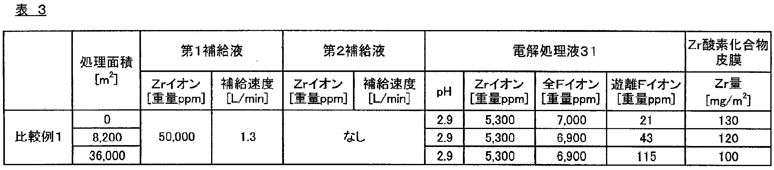
《比較例2》
循環槽50内の電解処理液31に対して、第1補給液を1.1L/minの補給量で補給し、上記第2補給液に代えて、固体補給剤として粉末の炭酸ジルコニウムを1分間当たり35g補給した以外は、実施例1と同様にして表面処理鋼板を作製し、同様に評価を行った。結果を表4に示す。なお、比較例2では、表面処理鋼板の作製は、電解処理の処理面積が25,000m2となるまで連続して行い、電解処理を行った処理面積が、表4に示すように、16,000m2、25,000m2となったタイミングで各評価を行った。
循環槽50内の電解処理液31に対して、第1補給液を1.1L/minの補給量で補給し、上記第2補給液に代えて、固体補給剤として粉末の炭酸ジルコニウムを1分間当たり35g補給した以外は、実施例1と同様にして表面処理鋼板を作製し、同様に評価を行った。結果を表4に示す。なお、比較例2では、表面処理鋼板の作製は、電解処理の処理面積が25,000m2となるまで連続して行い、電解処理を行った処理面積が、表4に示すように、16,000m2、25,000m2となったタイミングで各評価を行った。

《比較例3》
第1補給液および第2補給液の補給を、連続して行わずに、電解処理の処理面積が10,000m2となったタイミングで、1度だけ行うようにした以外は、実施例1と同様にして表面処理鋼板を作製し、同様に評価を行った。結果を表5に示す。なお、第1補給液および第2補給液の補給量は、電解処理液31中のZrイオン濃度および遊離Fイオン濃度が、電解処理開始時の値に近い値となる量とした。また、比較例3では、表面処理鋼板の作製は、電解処理の処理面積が20,000m2となるまで連続して行い、電解処理を行った処理面積が、表5に示すように、10,000m2、20,000m2となったタイミングで各評価を行った。さらに、比較例3では、表5に示すように、電解処理液31における化合物の析出の有無を、電解処理液31の外観を観察することで確認した。
第1補給液および第2補給液の補給を、連続して行わずに、電解処理の処理面積が10,000m2となったタイミングで、1度だけ行うようにした以外は、実施例1と同様にして表面処理鋼板を作製し、同様に評価を行った。結果を表5に示す。なお、第1補給液および第2補給液の補給量は、電解処理液31中のZrイオン濃度および遊離Fイオン濃度が、電解処理開始時の値に近い値となる量とした。また、比較例3では、表面処理鋼板の作製は、電解処理の処理面積が20,000m2となるまで連続して行い、電解処理を行った処理面積が、表5に示すように、10,000m2、20,000m2となったタイミングで各評価を行った。さらに、比較例3では、表5に示すように、電解処理液31における化合物の析出の有無を、電解処理液31の外観を観察することで確認した。
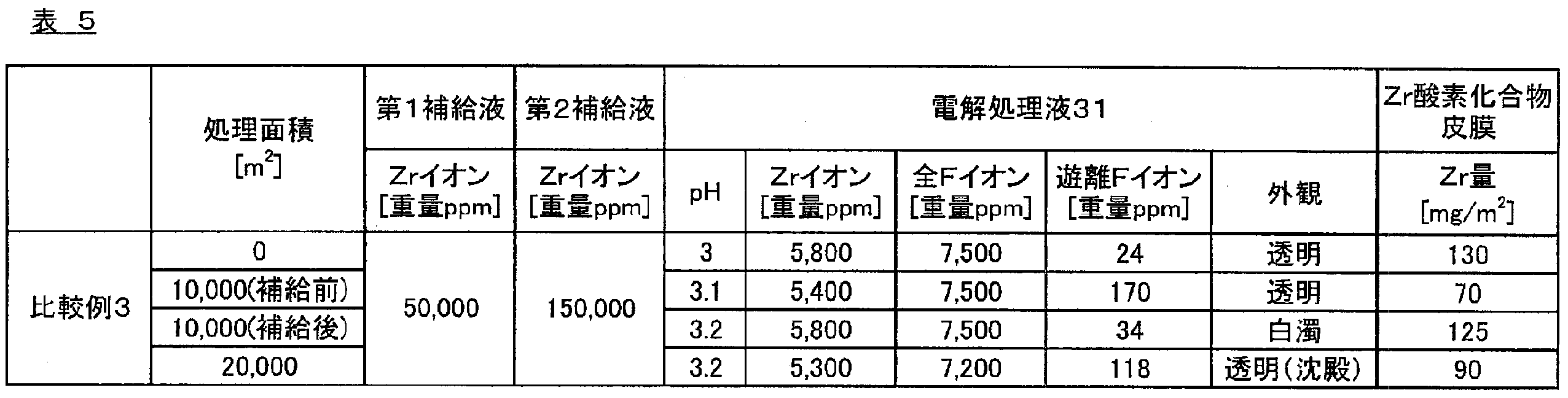
表1,2に示すように、フッ化ジルコニウム化合物(A)を溶解させた第1補給液と、フッ素非含有ジルコニウム化合物(B)を溶解させた第2補給液とを継続的に補給し、電解処理液31中のZrイオン濃度を3,000~10,000重量ppmとした実施例1,2は、電解処理液中のZrイオン濃度および遊離Fイオン濃度が、電解処理の処理面積によってほとんど変化せず、安定していた。さらに、実施例1,2は、Zr酸素化合物皮膜のZr量を125~135mg/m2と十分な量とすることができるとともに、形成したZr酸素化合物皮膜のZr量に基づいて算出したZr酸素化合物の形成速度は、70mg/(m2・sec)以上の高速であり、Zr酸素化合物の形成性に優れるものであった。
一方、表3に示すように、フッ化ジルコニウム化合物(A)を溶解させた第1補給液のみを補給した比較例1は、電解処理液31中の遊離Fイオン濃度が、電解処理の処理面積が大きくなるにつれて増加してしまい、形成したZr酸素化合物皮膜のZr量に基づいて算出したZr酸素化合物の形成速度が56mg/(m2・sec)と低速となってしまった。また、表4に示すように、フッ素非含有ジルコニウム化合物(B)を溶解させた第2補給液に代えて、粉末の炭酸ジルコニウムを補給した比較例2は、電解処理液31中のZrイオン濃度および遊離Fイオン濃度は、電解処理の処理面積によらず安定していたが、電解処理槽30および循環槽50の底には沈殿物が見られ、補給した炭酸ジルコニウムの一部が電解処理液31に溶解していないことが分かった。さらに、表5に示すように、上記第1補給液および第2補給液の補給を継続的に行わなかった比較例3は、電解処理液31中の遊離Fイオン濃度が、電解処理の処理面積が大きくなるにつれて増加してしまい、形成したZr酸素化合物皮膜のZr量に基づいて算出したZr酸素化合物の形成速度が40mg/(m2・sec)と低速となってしまった。加えて、比較例3では、電解処理液31において白濁や沈殿が確認され、電解処理液31中において化合物が析出していたことが確認された。このような化合物の析出は、第1補給液および第2補給液の補給が遅れたことに起因して発生したものと考えられる。すなわち、第1補給液および第2補給液の補給の遅れにより、電解処理液31中の遊離Fイオン濃度が大きくなり、これにより、基材1が過度にエッチングされてFeイオンが溶出し、このFeイオンが遊離Fイオンと反応してフッ化鉄になり、第1補給液および第2補給液中のZr化合物を溶解させるのに必要な遊離Fイオンが減少したことにより、Zr化合物が析出したことに起因していると考えられる。このような析出物は板表面に異物として付着し、板の外観不良となるため好ましくない。
《実施例3》
原板として、低炭素冷延鋼板(厚さ0.2mm、幅200mm)を準備した。そして、準備した鋼板について、市販の脱脂剤(日本クエーカーケミカル社製、フォーミュラー 618-TK2)を溶解させたアルカリ水溶液中で電解脱脂した後、水洗し、続いて硫酸水溶液に浸漬して酸洗した後、図3に示す表面処理ライン100bを用いて、下記条件にて電解処理を行い、鋼板上にZr酸素化合物皮膜を形成した。なお、電解処理は、鋼板上に形成するZr酸素化合物皮膜がZr量で片面80mg/m2となるようにして、電解処理の処理面積が2,000m2となるまで連続して行った。次いで、Zr酸素化合物皮膜を形成した鋼板を水洗し、乾燥させることで表面処理鋼板を得た。
電解処理液31の組成:Zr化合物としてフッ化ジルコニウムアンモニウムを溶解させて得た、Zrイオン濃度6000重量ppm、全Fイオン濃度7600重量ppm、硝酸イオン濃度13230重量ppmの水溶液
電解処理液31の温度:40℃
ライン速度(鋼板の移動速度):20m/min
鋼板における電流密度:10A/dm2
トータル電解処理時間:1.8秒(0.6秒通電、1.2秒通電停止のサイクルを2回繰り返した際における、通電および通電停止の合計時間。)
原板として、低炭素冷延鋼板(厚さ0.2mm、幅200mm)を準備した。そして、準備した鋼板について、市販の脱脂剤(日本クエーカーケミカル社製、フォーミュラー 618-TK2)を溶解させたアルカリ水溶液中で電解脱脂した後、水洗し、続いて硫酸水溶液に浸漬して酸洗した後、図3に示す表面処理ライン100bを用いて、下記条件にて電解処理を行い、鋼板上にZr酸素化合物皮膜を形成した。なお、電解処理は、鋼板上に形成するZr酸素化合物皮膜がZr量で片面80mg/m2となるようにして、電解処理の処理面積が2,000m2となるまで連続して行った。次いで、Zr酸素化合物皮膜を形成した鋼板を水洗し、乾燥させることで表面処理鋼板を得た。
電解処理液31の組成:Zr化合物としてフッ化ジルコニウムアンモニウムを溶解させて得た、Zrイオン濃度6000重量ppm、全Fイオン濃度7600重量ppm、硝酸イオン濃度13230重量ppmの水溶液
電解処理液31の温度:40℃
ライン速度(鋼板の移動速度):20m/min
鋼板における電流密度:10A/dm2
トータル電解処理時間:1.8秒(0.6秒通電、1.2秒通電停止のサイクルを2回繰り返した際における、通電および通電停止の合計時間。)
また、本実施例においては、電解処理を行っている間に、電解処理液31に対して、電解処理液31のpHが3.0付近となるように、硝酸水溶液またはアンモニア水を適宜添加しながら、第1補給液槽70および第2補給液槽80により、Zr化合物を溶解させた補給液を補給した。具体的には、下記条件にて、第1補給液槽82から第1補給液を、第2補給液槽84から第2補給液をそれぞれ連続的に補給した。
第1補給液:フッ化ジルコニウムアンモニウムをZrイオン濃度で50g/Lとなるように溶解させた水溶液
第1補給液の補給量:電解処理による処理面積1m2当たり、Zr量で0.03gに相当する量を補給。
第2補給液:硝酸ジルコニウムをZrイオン濃度で150g/Lとなるように溶解させた水溶液
第2補給液の補給量:電解処理による処理面積1m2当たり、Zr量で0.1gに相当する量を補給。
第1補給液:フッ化ジルコニウムアンモニウムをZrイオン濃度で50g/Lとなるように溶解させた水溶液
第1補給液の補給量:電解処理による処理面積1m2当たり、Zr量で0.03gに相当する量を補給。
第2補給液:硝酸ジルコニウムをZrイオン濃度で150g/Lとなるように溶解させた水溶液
第2補給液の補給量:電解処理による処理面積1m2当たり、Zr量で0.1gに相当する量を補給。
さらに、電解処理を行っている間には、図3に示す表面処理ライン100bに示すように、循環槽50中の電解処理液31の一部を、ポンプ92により循環槽50と逆浸透膜処理装置93との間に循環させることで、逆浸透膜処理装置93による逆浸透膜処理を行った。
逆浸透膜:ポリテックス社製 型番:PTW(濃度2.0g/Lの塩化ナトリウム水溶液を透過させた際におけるナトリウムイオンおよび塩化物イオンの透過率が60重量%の逆浸透膜。)
逆浸透膜面積:6m2
逆浸透膜処理温度:20℃
圧力:0.1~0.3MPa
濃縮液流量:6~9L/min
透過液流量:1.0~1.5L/min
逆浸透膜:ポリテックス社製 型番:PTW(濃度2.0g/Lの塩化ナトリウム水溶液を透過させた際におけるナトリウムイオンおよび塩化物イオンの透過率が60重量%の逆浸透膜。)
逆浸透膜面積:6m2
逆浸透膜処理温度:20℃
圧力:0.1~0.3MPa
濃縮液流量:6~9L/min
透過液流量:1.0~1.5L/min
なお、本実施例においては、電解処理を行った処理面積が、表6に示すように、1,000m2、2,000m2となったタイミングで、それぞれ、循環槽50内の電解処理液31について、上述した方法にしたがって、成分分析および物性測定を行った。また、得られた表面処理鋼板については、上述した方法にしたがって、Zr酸素化合物皮膜中のZr量を測定した。結果を表6に示す。

電解処理を行っている間に、電解処理液31の一部を、逆浸透膜処理装置93により逆浸透膜処理した実施例3においては、表6に示すように、電解処理の途中のいずれのタイミングで測定した電解処理液31についても、Zrイオン濃度、硝酸イオン濃度、全Fイオン濃度、および遊離Fイオン濃度がほぼ一定に保たれており、加えて、形成したZr酸素化合物皮膜のZr量もほぼ一定となっていたため、電解処理の処理性に優れていることが確認された。
《参考例1》
原板として、低炭素冷延鋼板(厚さ0.2mm、幅1,000mm)を準備した。そして、準備した鋼板について、市販の脱脂剤(日本クエーカーケミカル社製、フォーミュラー 618-TK2)を溶解させたアルカリ水溶液中で電解脱脂した後、水洗し、続いて硫酸水溶液に浸漬して酸洗した後、図1に示す表面処理ライン100を用いて、下記条件にて電解処理を行い、鋼板上にZr酸素化合物皮膜を形成した。次いで、Zr酸素化合物皮膜を形成した鋼板を水洗し、乾燥させることで表面処理鋼板を得た。
電解処理液31の組成:Zr化合物としてフッ化ジルコニウムアンモニウムを溶解させ、さらに硝酸水溶液を添加して得た、Zrイオン濃度5,500重量ppm、全Fイオン濃度7,000重量ppm、硝酸イオン濃度2,000重量ppm、遊離Fイオン濃度33重量ppmの水溶液
電解処理液31のpH:3.0(アンモニアにてpH調整を実施)
電解処理液31の温度:40℃
ライン速度(鋼板の移動速度):150m/min
鋼板における電流密度:10A/dm3
通電時間:0.6秒
停止時間:0.1秒
原板として、低炭素冷延鋼板(厚さ0.2mm、幅1,000mm)を準備した。そして、準備した鋼板について、市販の脱脂剤(日本クエーカーケミカル社製、フォーミュラー 618-TK2)を溶解させたアルカリ水溶液中で電解脱脂した後、水洗し、続いて硫酸水溶液に浸漬して酸洗した後、図1に示す表面処理ライン100を用いて、下記条件にて電解処理を行い、鋼板上にZr酸素化合物皮膜を形成した。次いで、Zr酸素化合物皮膜を形成した鋼板を水洗し、乾燥させることで表面処理鋼板を得た。
電解処理液31の組成:Zr化合物としてフッ化ジルコニウムアンモニウムを溶解させ、さらに硝酸水溶液を添加して得た、Zrイオン濃度5,500重量ppm、全Fイオン濃度7,000重量ppm、硝酸イオン濃度2,000重量ppm、遊離Fイオン濃度33重量ppmの水溶液
電解処理液31のpH:3.0(アンモニアにてpH調整を実施)
電解処理液31の温度:40℃
ライン速度(鋼板の移動速度):150m/min
鋼板における電流密度:10A/dm3
通電時間:0.6秒
停止時間:0.1秒
なお、本参考例においては、電解処理を開始する前の電解処理液31について、上述した方法にしたがって、成分分析および物性測定を行った。また、本参考例において得られた表面処理鋼板について、上述した方法にしたがって、Zr酸素化合物皮膜のZr量の測定、および電解処理の処理安定性(Zr)の評価を行った。結果を表7に示す。
《参考例2》
電解処理に用いる電解処理液31に添加する遊離Fイオン濃度を調整することで、電解処理液31中の遊離Fイオン濃度を75重量ppmとした以外は、参考例1と同様にして表面処理鋼板を作製し、電解処理液31の成分分析および物性測定、Zr酸素化合物皮膜のZr量の測定および電解処理の処理安定性(Zr)の評価を行った。結果を表7に示す。
電解処理に用いる電解処理液31に添加する遊離Fイオン濃度を調整することで、電解処理液31中の遊離Fイオン濃度を75重量ppmとした以外は、参考例1と同様にして表面処理鋼板を作製し、電解処理液31の成分分析および物性測定、Zr酸素化合物皮膜のZr量の測定および電解処理の処理安定性(Zr)の評価を行った。結果を表7に示す。
《参考例3》
電解処理に用いる電解処理液31に添加する遊離Fイオン濃度を調整することで、電解処理液31中の遊離Fイオン濃度を115重量ppmとした以外は、参考例1と同様にして表面処理鋼板を作製し、電解処理液31の成分分析および物性測定、Zr酸素化合物皮膜のZr量の測定および電解処理の処理安定性(Zr)の評価を行った。結果を表7に示す。
電解処理に用いる電解処理液31に添加する遊離Fイオン濃度を調整することで、電解処理液31中の遊離Fイオン濃度を115重量ppmとした以外は、参考例1と同様にして表面処理鋼板を作製し、電解処理液31の成分分析および物性測定、Zr酸素化合物皮膜のZr量の測定および電解処理の処理安定性(Zr)の評価を行った。結果を表7に示す。
《参考例4》
電解処理に用いる電解処理液31に添加する遊離Fイオン濃度を調整することで、電解処理液31中の遊離Fイオン濃度を145重量ppmとした以外は、参考例1と同様にして表面処理鋼板を作製し、電解処理液31の成分分析および物性測定、Zr酸素化合物皮膜のZr量の測定および電解処理の処理安定性(Zr)の評価を行った。結果を表7に示す。
電解処理に用いる電解処理液31に添加する遊離Fイオン濃度を調整することで、電解処理液31中の遊離Fイオン濃度を145重量ppmとした以外は、参考例1と同様にして表面処理鋼板を作製し、電解処理液31の成分分析および物性測定、Zr酸素化合物皮膜のZr量の測定および電解処理の処理安定性(Zr)の評価を行った。結果を表7に示す。
《参考例5》
電解処理に用いる電解処理液31に添加する遊離Fイオン濃度を調整することで、電解処理液31中の遊離Fイオン濃度を160重量ppmとした以外は、参考例1と同様にして表面処理鋼板を作製し、電解処理液31の成分分析および物性測定、Zr酸素化合物皮膜のZr量の測定および電解処理の処理安定性(Zr)の評価を行った。結果を表7に示す。
電解処理に用いる電解処理液31に添加する遊離Fイオン濃度を調整することで、電解処理液31中の遊離Fイオン濃度を160重量ppmとした以外は、参考例1と同様にして表面処理鋼板を作製し、電解処理液31の成分分析および物性測定、Zr酸素化合物皮膜のZr量の測定および電解処理の処理安定性(Zr)の評価を行った。結果を表7に示す。
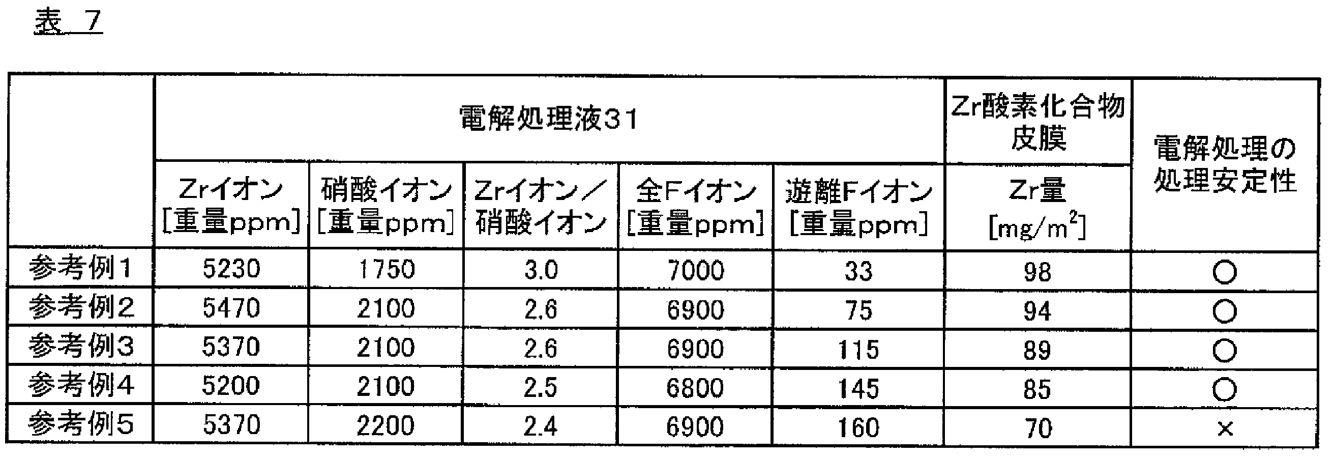
表7に示すように、電解処理液31における、遊離Fイオン濃度を150ppm以下とした参考例1~4においては、電解処理の条件(電解処理液31のpHおよび温度、電流密度、トータル電解処理時間)を同一とした場合に、鋼板上に形成されたZr酸素化合物皮膜のZr量は、同等の値であったため、これにより、Zr酸素化合物皮膜の形成量の制御が容易となり、電解処理の処理安定性に優れていることが確認された。
一方、表7に示すように、電解処理液31における遊離Fイオン濃度が160重量ppmであった参考例5は、上述した参考例1と電解処理の条件(電解処理液31のpHおよび温度、電流密度、トータル電解処理時間)を同一としたにもかかわらず、参考例1と比較して、鋼板上に形成されたZr酸素化合物皮膜のZr量が少なくなりすぎてしまったため、これにより、Zr酸素化合物皮膜の形成量の制御が難しくなり、電解処理の処理安定性に劣ることが確認された。
これにより、上述した、参考例1~5によれば、電解処理液31において、遊離Fイオン濃度を150重量ppm以下に制御することにより、形成するZr酸素化合物皮膜の形成量の制御が容易となり、電解処理の処理安定性が安定することが確認された。
《参考例6》
原板として、低炭素冷延鋼板(厚さ0.2mm、幅200mm)を準備した。そして、準備した鋼板について、市販の脱脂剤(日本クエーカーケミカル社製、フォーミュラー 618-TK2)を溶解させたアルカリ水溶液中で電解脱脂した後、水洗し、続いて硫酸水溶液に浸漬して酸洗した後、図1に示す表面処理ライン100のうち、循環槽50を接続していない状態の電解処理槽30により、下記条件にて電解処理を行い、鋼板上にZr酸素化合物皮膜を形成した。次いで、Zr酸素化合物皮膜を形成した鋼板を水洗し、乾燥させることで表面処理鋼板を得た。
電解処理液31の組成:Zr化合物としてフッ化ジルコニウムアンモニウムを溶解させ、Zrイオン濃度6,000重量ppm、全Fイオン濃度7,600重量ppmとし、さらに硝酸イオン濃度が2,000重量ppmとなるように硝酸水溶液を添加して、「Zrイオンの重量濃度/硝酸イオンの重量濃度」を3.0とした水溶液
電解処理液31のpH:3.0(アンモニア水を添加することでpH調整)
電解処理液31の温度:40℃
鋼板における電流密度:4A/dm2
トータル電解処理時間:7.15秒(0.15秒通電、0.5秒通電停止のサイクルを11回繰り返した際における、通電および通電停止の合計時間。)
原板として、低炭素冷延鋼板(厚さ0.2mm、幅200mm)を準備した。そして、準備した鋼板について、市販の脱脂剤(日本クエーカーケミカル社製、フォーミュラー 618-TK2)を溶解させたアルカリ水溶液中で電解脱脂した後、水洗し、続いて硫酸水溶液に浸漬して酸洗した後、図1に示す表面処理ライン100のうち、循環槽50を接続していない状態の電解処理槽30により、下記条件にて電解処理を行い、鋼板上にZr酸素化合物皮膜を形成した。次いで、Zr酸素化合物皮膜を形成した鋼板を水洗し、乾燥させることで表面処理鋼板を得た。
電解処理液31の組成:Zr化合物としてフッ化ジルコニウムアンモニウムを溶解させ、Zrイオン濃度6,000重量ppm、全Fイオン濃度7,600重量ppmとし、さらに硝酸イオン濃度が2,000重量ppmとなるように硝酸水溶液を添加して、「Zrイオンの重量濃度/硝酸イオンの重量濃度」を3.0とした水溶液
電解処理液31のpH:3.0(アンモニア水を添加することでpH調整)
電解処理液31の温度:40℃
鋼板における電流密度:4A/dm2
トータル電解処理時間:7.15秒(0.15秒通電、0.5秒通電停止のサイクルを11回繰り返した際における、通電および通電停止の合計時間。)
なお、本参考例においては、電解処理を開始する前の電解処理液31について、上述した方法にしたがって、成分分析および物性測定を行った。また、本参考例において得られた表面処理鋼板について、上述した方法にしたがって、Zr酸素化合物皮膜のZr量の測定、および電解処理の処理安定性(Zr)の評価を行った。結果を表8に示す。
次いで、得られた表面処理鋼板を、250℃に加熱し、表面処理鋼板の一方の面上に、ラミネートロールを用いて、イソフタル酸を15mol%共重合化してなる無配向のポリエチレンテレフタレート(PET)フィルム(厚さ20μm)を熱圧着し、直ちに水冷することにより、有機樹脂層を形成した。これにより、本参考例においては、表面処理板の一方の面のみに有機樹脂層が形成され、もう一方の面はZr酸素化合物皮膜が露出した有機樹脂被覆鋼板を得た。次いで、このようにして得られた有機樹脂被覆鋼板について、上述した方法にしたがって、クロスカット耐食性の評価を行った。結果を表8に示す。
《参考例7》
電解処理に用いる電解処理液31に添加する硝酸水溶液の量を調整することで、電解処理液31中の硝酸イオン濃度を12,000重量ppmとし、「Zrイオンの重量濃度/硝酸イオンの重量濃度」を0.5とした以外は、参考例6と同様にして表面処理鋼板および有機樹脂被覆鋼板を作製し、同様にして、電解処理液31の成分分析および物性測定、Zr酸素化合物皮膜のZr量の測定、電解処理の処理安定性(Zr)の評価、ならびにクロスカット耐食性の評価を行った。結果を表8に示す。
電解処理に用いる電解処理液31に添加する硝酸水溶液の量を調整することで、電解処理液31中の硝酸イオン濃度を12,000重量ppmとし、「Zrイオンの重量濃度/硝酸イオンの重量濃度」を0.5とした以外は、参考例6と同様にして表面処理鋼板および有機樹脂被覆鋼板を作製し、同様にして、電解処理液31の成分分析および物性測定、Zr酸素化合物皮膜のZr量の測定、電解処理の処理安定性(Zr)の評価、ならびにクロスカット耐食性の評価を行った。結果を表8に示す。
《参考例8》
電解処理に用いる電解処理液31に添加する硝酸水溶液の量を調整することで、電解処理液31中の硝酸イオン濃度を14,000重量ppmとし、「Zrイオンの重量濃度/硝酸イオンの重量濃度」を0.43とした以外は、参考例6と同様にして表面処理鋼板および有機樹脂被覆鋼板を作製し、同様にして、電解処理液31の成分分析および物性測定、Zr酸素化合物皮膜のZr量の測定、電解処理の処理安定性(Zr)の評価、ならびにクロスカット耐食性の評価を行った。結果を表8に示す。
電解処理に用いる電解処理液31に添加する硝酸水溶液の量を調整することで、電解処理液31中の硝酸イオン濃度を14,000重量ppmとし、「Zrイオンの重量濃度/硝酸イオンの重量濃度」を0.43とした以外は、参考例6と同様にして表面処理鋼板および有機樹脂被覆鋼板を作製し、同様にして、電解処理液31の成分分析および物性測定、Zr酸素化合物皮膜のZr量の測定、電解処理の処理安定性(Zr)の評価、ならびにクロスカット耐食性の評価を行った。結果を表8に示す。
《参考例9》
電解処理を行う際におけるトータル電解処理時間を5.2秒(0.15秒通電、0.5秒通電停止のサイクルを8回繰り返した際における、通電および通電停止の合計時間。)とした以外は、参考例8と同様にして表面処理鋼板および有機樹脂被覆鋼板を作製し、同様にして、電解処理液31の成分分析および物性測定、Zr酸素化合物皮膜のZr量の測定、電解処理の処理安定性(Zr)の評価、ならびにクロスカット耐食性の評価を行った。結果を表8に示す。
電解処理を行う際におけるトータル電解処理時間を5.2秒(0.15秒通電、0.5秒通電停止のサイクルを8回繰り返した際における、通電および通電停止の合計時間。)とした以外は、参考例8と同様にして表面処理鋼板および有機樹脂被覆鋼板を作製し、同様にして、電解処理液31の成分分析および物性測定、Zr酸素化合物皮膜のZr量の測定、電解処理の処理安定性(Zr)の評価、ならびにクロスカット耐食性の評価を行った。結果を表8に示す。
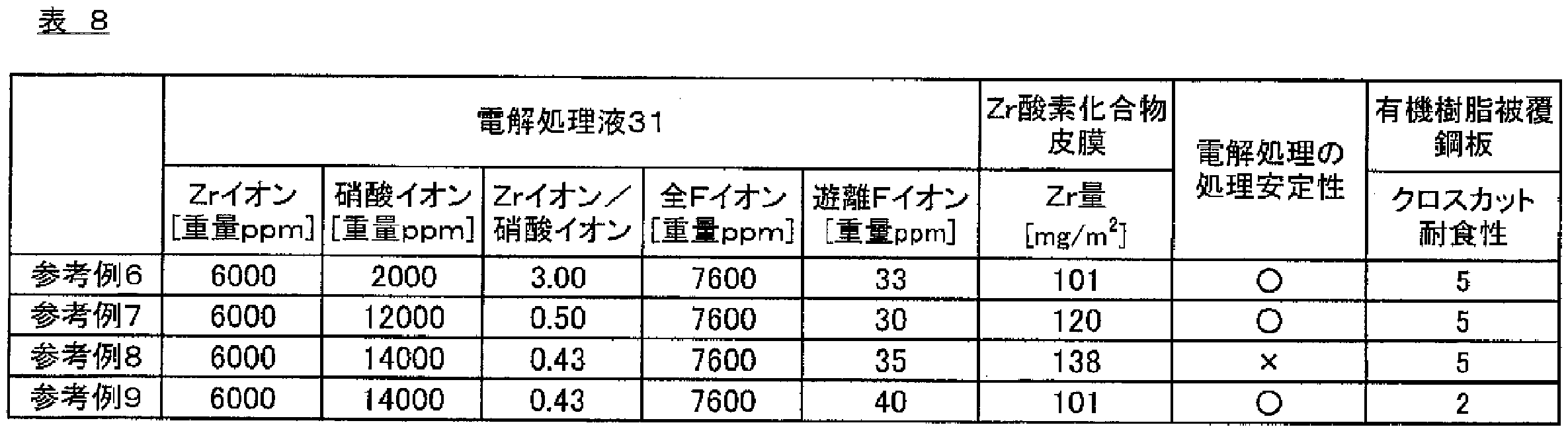
表8に示すように、電解処理液31における、Zrイオンおよび硝酸イオンの重量濃度の比を、「Zrイオンの重量濃度/硝酸イオンの重量濃度」で0.5以上とした参考例6,7は、電解処理の条件(電解処理液31のpHおよび温度、電流密度、トータル電解処理時間)を同一とした場合に、鋼板上に形成されたZr酸素化合物皮膜のZr量は、同等の値であったため、これにより、Zr酸素化合物皮膜の形成量の制御が容易となり、電解処理の処理安定性に優れていることが確認された。また、参考例6,7は、得られた表面処理鋼板の表面に有機樹脂層を形成してなる有機樹脂被覆鋼板について、クロスカット耐食性の評価結果が良好であり、耐食性に優れていることが確認された。
一方、表8に示すように、電解処理液31における「Zrイオンの重量濃度/硝酸イオンの重量濃度」が0.50未満であった参考例8は、上述した参考例6と電解処理の条件(電解処理液31のpHおよび温度、電流密度、トータル電解処理時間)を同一としたにもかかわらず、参考例1と比較して、鋼板上に形成されたZr酸素化合物皮膜のZr量が多くなりすぎてしまったため、これにより、Zr酸素化合物皮膜の形成量の制御が難しくなり、電解処理の処理安定性に劣ることが確認された。また、電解処理液31における「Zrイオンの重量濃度/硝酸イオンの重量濃度」が0.50未満であった参考例9は、トータル電解処理時間を短くすることで、鋼板上に形成するZr酸素化合物皮膜のZr量を、上述した参考例6と同等の値としたが、クロスカット耐食性の評価結果が悪く、耐食性に劣ることが確認された。
これにより、上述した、参考例6~9によれば、電解処理液31において、Zrイオンの濃度に対する過剰に存在することで皮膜の形成を阻害する成分の濃度を適切に制御することにより、形成するZr酸素化合物皮膜の形成量の制御が容易となり、電解処理の処理安定性が向上することが確認された。すなわち、上述した実施例3のように、電解処理を行っている間に、電解処理液31の一部に対して、逆浸透膜処理装置93による逆浸透膜処理を施し、電解処理液31中の硝酸イオンの重量濃度を制御することにより、「Zrイオンの重量濃度/硝酸イオンの重量濃度」を0.50以上とすることができれば、電解処理の処理安定性が向上し、得られる有機樹脂被覆鋼板の耐食性が向上することが確認された。
1…基材
100,100a,100b…表面処理ライン
11,13…コンダクターロール
12…シンクロール
20a,20b,20c,20d…アノード
30…電解処理槽
31…電解処理液
40…計測装置
50…循環槽
60…ポンプ
70…第1補給液槽
80…第2補給液槽
90…ミックスタンク
91…ポンプ
92…ポンプ
93…逆浸透膜処理装置
94…透過液槽
100,100a,100b…表面処理ライン
11,13…コンダクターロール
12…シンクロール
20a,20b,20c,20d…アノード
30…電解処理槽
31…電解処理液
40…計測装置
50…循環槽
60…ポンプ
70…第1補給液槽
80…第2補給液槽
90…ミックスタンク
91…ポンプ
92…ポンプ
93…逆浸透膜処理装置
94…透過液槽
Claims (8)
- 鋼板を、ZrイオンおよびFイオンを含む電解処理液に浸漬させ、電解処理を連続的に行うことにより、前記鋼板上に、Zr酸素化合物を主成分とする皮膜を、該皮膜中のZr量が30mg/m2以上となるように形成する表面処理鋼板の製造方法において、
前記電解処理液中のZrイオンの濃度が3,000~10,000重量ppm、pHが2~4であり、
前記電解処理液に対して、フッ化ジルコニウム化合物(A)をZrイオンの濃度で10,000~250,000重量ppmの範囲で含有し、かつ、pHが5以下である第1補給液と、フッ素非含有ジルコニウム化合物(B)をZrイオンの濃度で10,000~200,000重量ppmの範囲で含有し、かつ、pHが5以下である第2補給液とを、それぞれ継続的に補給することを特徴とする表面処理鋼板の製造方法。 - 前記フッ化ジルコニウム化合物(A)として、フッ化ジルコニウムアンモニウムを用いることを特徴とする請求項1に記載の表面処理鋼板の製造方法。
- 前記フッ素非含有ジルコニウム化合物(B)として、オキシ硝酸ジルコニウムを用いることを特徴とする請求項1または2に記載の表面処理鋼板の製造方法。
- 前記電解処理液中における遊離Fイオンの濃度を、イオン電極法によりpH3.0、温度25℃の条件にて測定した値で、10~150重量ppmの範囲に制御することを特徴とする請求項1~3のいずれかに記載の表面処理鋼板の製造方法。
- 前記電解処理液中におけるZrイオンと硝酸イオンとの重量濃度比を、「Zrイオンの重量濃度/硝酸イオンの重量濃度」で0.45以上とすることを特徴とする請求項1~4のいずれかに記載の表面処理鋼板の製造方法。
- 前記鋼板上に前記皮膜を形成する際の形成速度を、単位面積および単位時間当たりのZr量で70mg/(m2・sec)以上とすることを特徴とする請求項1~5のいずれかに記載の表面処理鋼板の製造方法。
- 前記電解処理液の一部を取り出し、逆浸透膜を用いて、透過液と濃縮液とに分離し濃縮液を前記電解処理液に戻す逆浸透膜処理工程を有することを特徴とする請求項1~6のいずれかに記載の表面処理鋼板の製造方法。
- 前記逆浸透膜として、濃度2.0g/Lの塩化ナトリウム水溶液を透過させた場合に、ナトリウムイオンおよび塩化物イオンの透過率が60重量%以上である逆浸透膜を用いることを特徴とする請求項7に記載の表面処理鋼板の製造方法。
Applications Claiming Priority (2)
| Application Number | Priority Date | Filing Date | Title |
|---|---|---|---|
| JP2014-151606 | 2014-07-25 | ||
| JP2014151606A JP5916807B2 (ja) | 2014-07-25 | 2014-07-25 | 表面処理鋼板の製造方法 |
Publications (1)
| Publication Number | Publication Date |
|---|---|
| WO2016013561A1 true WO2016013561A1 (ja) | 2016-01-28 |
Family
ID=55163085
Family Applications (1)
| Application Number | Title | Priority Date | Filing Date |
|---|---|---|---|
| PCT/JP2015/070780 Ceased WO2016013561A1 (ja) | 2014-07-25 | 2015-07-22 | 表面処理鋼板の製造方法 |
Country Status (2)
| Country | Link |
|---|---|
| JP (1) | JP5916807B2 (ja) |
| WO (1) | WO2016013561A1 (ja) |
Families Citing this family (1)
| Publication number | Priority date | Publication date | Assignee | Title |
|---|---|---|---|---|
| WO2025164402A1 (ja) * | 2024-01-30 | 2025-08-07 | 株式会社村田製作所 | めっき組成物およびその製造方法 |
Citations (5)
| Publication number | Priority date | Publication date | Assignee | Title |
|---|---|---|---|---|
| JP2007262577A (ja) * | 2006-03-01 | 2007-10-11 | Nippon Paint Co Ltd | 金属表面処理用組成物、金属表面処理方法、及び金属材料 |
| US20110259756A1 (en) * | 2010-04-22 | 2011-10-27 | Shigeru Hirano | Method of production of chemically treated steel sheet |
| WO2011149047A1 (ja) * | 2010-05-28 | 2011-12-01 | 東洋製罐株式会社 | 表面処理浴、この表面処理浴を用いた表面処理鋼板の製造方法及びこの製造方法から成る表面処理鋼板 |
| JP4996409B2 (ja) * | 2007-09-28 | 2012-08-08 | 新日本製鐵株式会社 | 化成処理被覆鋼板の製造方法 |
| JP5215509B1 (ja) * | 2011-11-30 | 2013-06-19 | 日本パーカライジング株式会社 | 補給剤、表面処理鋼板の製造方法 |
-
2014
- 2014-07-25 JP JP2014151606A patent/JP5916807B2/ja active Active
-
2015
- 2015-07-22 WO PCT/JP2015/070780 patent/WO2016013561A1/ja not_active Ceased
Patent Citations (5)
| Publication number | Priority date | Publication date | Assignee | Title |
|---|---|---|---|---|
| JP2007262577A (ja) * | 2006-03-01 | 2007-10-11 | Nippon Paint Co Ltd | 金属表面処理用組成物、金属表面処理方法、及び金属材料 |
| JP4996409B2 (ja) * | 2007-09-28 | 2012-08-08 | 新日本製鐵株式会社 | 化成処理被覆鋼板の製造方法 |
| US20110259756A1 (en) * | 2010-04-22 | 2011-10-27 | Shigeru Hirano | Method of production of chemically treated steel sheet |
| WO2011149047A1 (ja) * | 2010-05-28 | 2011-12-01 | 東洋製罐株式会社 | 表面処理浴、この表面処理浴を用いた表面処理鋼板の製造方法及びこの製造方法から成る表面処理鋼板 |
| JP5215509B1 (ja) * | 2011-11-30 | 2013-06-19 | 日本パーカライジング株式会社 | 補給剤、表面処理鋼板の製造方法 |
Also Published As
| Publication number | Publication date |
|---|---|
| JP5916807B2 (ja) | 2016-05-11 |
| JP2016029197A (ja) | 2016-03-03 |
Similar Documents
| Publication | Publication Date | Title |
|---|---|---|
| US20040245113A1 (en) | Tin alloy electroplating system | |
| JP4996409B2 (ja) | 化成処理被覆鋼板の製造方法 | |
| CN105917031A (zh) | 含三价铬的电镀槽液和沉积铬的方法 | |
| JP6989646B2 (ja) | ブラックプレート又はブリキの表面を不動態化するための方法及びその方法を実施するための電解システム | |
| US20110259756A1 (en) | Method of production of chemically treated steel sheet | |
| JP2009525404A (ja) | 基板表面をコーティングする方法および装置 | |
| JP5916807B2 (ja) | 表面処理鋼板の製造方法 | |
| US20020162752A1 (en) | Electrolytic phosphate chemical treatment method | |
| CN104105822B (zh) | 补给剂、表面处理钢板的制造方法 | |
| JP5859072B1 (ja) | 表面処理鋼板の製造方法 | |
| CN105102681B (zh) | 表面处理钢板的制造方法 | |
| JP6949095B2 (ja) | 三価クロム化合物を含む電解液を使用してクロムおよび酸化クロムのコーティングで被覆された金属ストリップの製造方法 | |
| US12006585B2 (en) | Method for depositing a chromium or chromium alloy layer and plating apparatus | |
| JP7808034B2 (ja) | 亜鉛ニッケル合金を基材上に堆積するための方法およびシステム | |
| JPWO2014115203A1 (ja) | クロムめっき浴及びそれを使用したクロムめっき皮膜の形成方法 | |
| TW201829850A (zh) | 電解處理用金屬表面處理劑 | |
| JPS5854200B2 (ja) | 電気メツキ浴における金属イオンの供給方法 | |
| JP6517501B2 (ja) | ストライク銅めっき液およびストライク銅めっき方法 | |
| CN104711648B (zh) | 闪镀铜镀敷液 | |
| KR101365662B1 (ko) | 무전해 니켈-인 도금방법 | |
| JP2005344208A (ja) | 無電解ニッケルめっき液の処理方法 | |
| Shuker et al. | Why functional trivalent chromium fails and hexavalent chromium is environmentally friendly | |
| HEYDARI et al. | Effect of Temperature and Co2+ Concentration of Bath on Composition of Zn-Co Alloy Coatings | |
| JPH0768633B2 (ja) | 鉄―亜鉛合金電気めっき鋼材の製造方法 | |
| JPH0361756B2 (ja) |
Legal Events
| Date | Code | Title | Description |
|---|---|---|---|
| 121 | Ep: the epo has been informed by wipo that ep was designated in this application |
Ref document number: 15825449 Country of ref document: EP Kind code of ref document: A1 |
|
| NENP | Non-entry into the national phase |
Ref country code: DE |
|
| 122 | Ep: pct application non-entry in european phase |
Ref document number: 15825449 Country of ref document: EP Kind code of ref document: A1 |