WO2016013408A1 - 押出成形用フラットダイ及びフィルム成形方法 - Google Patents
押出成形用フラットダイ及びフィルム成形方法 Download PDFInfo
- Publication number
- WO2016013408A1 WO2016013408A1 PCT/JP2015/069789 JP2015069789W WO2016013408A1 WO 2016013408 A1 WO2016013408 A1 WO 2016013408A1 JP 2015069789 W JP2015069789 W JP 2015069789W WO 2016013408 A1 WO2016013408 A1 WO 2016013408A1
- Authority
- WO
- WIPO (PCT)
- Prior art keywords
- discharge port
- groove
- flat die
- sealing member
- die
- Prior art date
- Legal status (The legal status is an assumption and is not a legal conclusion. Google has not performed a legal analysis and makes no representation as to the accuracy of the status listed.)
- Ceased
Links
Images






Classifications
-
- B—PERFORMING OPERATIONS; TRANSPORTING
- B29—WORKING OF PLASTICS; WORKING OF SUBSTANCES IN A PLASTIC STATE IN GENERAL
- B29C—SHAPING OR JOINING OF PLASTICS; SHAPING OF MATERIAL IN A PLASTIC STATE, NOT OTHERWISE PROVIDED FOR; AFTER-TREATMENT OF THE SHAPED PRODUCTS, e.g. REPAIRING
- B29C48/00—Extrusion moulding, i.e. expressing the moulding material through a die or nozzle which imparts the desired form; Apparatus therefor
- B29C48/03—Extrusion moulding, i.e. expressing the moulding material through a die or nozzle which imparts the desired form; Apparatus therefor characterised by the shape of the extruded material at extrusion
- B29C48/07—Flat, e.g. panels
- B29C48/08—Flat, e.g. panels flexible, e.g. films
-
- B—PERFORMING OPERATIONS; TRANSPORTING
- B29—WORKING OF PLASTICS; WORKING OF SUBSTANCES IN A PLASTIC STATE IN GENERAL
- B29C—SHAPING OR JOINING OF PLASTICS; SHAPING OF MATERIAL IN A PLASTIC STATE, NOT OTHERWISE PROVIDED FOR; AFTER-TREATMENT OF THE SHAPED PRODUCTS, e.g. REPAIRING
- B29C48/00—Extrusion moulding, i.e. expressing the moulding material through a die or nozzle which imparts the desired form; Apparatus therefor
- B29C48/25—Component parts, details or accessories; Auxiliary operations
- B29C48/30—Extrusion nozzles or dies
- B29C48/305—Extrusion nozzles or dies having a wide opening, e.g. for forming sheets
- B29C48/31—Extrusion nozzles or dies having a wide opening, e.g. for forming sheets being adjustable, i.e. having adjustable exit sections
Definitions
- the present invention relates to a flat die for extrusion molding and a film molding method for discharging a molten material.
- an extruder for extruding a molten material such as a resin material melted by a melt plasticizer is used.
- the extruder has a pipe through which the extruded molten material flows, and has a flat die for extrusion molding (hereinafter referred to as a flat die) having a slit-like discharge port for discharging the molten material into a thin and wide film. Is connected to the end of the pipe.
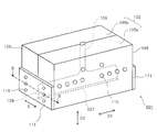
- FIG. 8 shows a schematic perspective view of a conventional flat die.
- FIG. 9 is a cross-sectional view taken along the line BB in FIG. 8 of the main part of the conventional flat die.
- a conventional flat die 101 includes a die body 105 in which a flow path 106 of a molten material is formed.
- the die main body 105 is configured by combining a pair of main bodies 105 a and 105 b and using a plurality of fastening bolts 110.
- a slit-like discharge port 107 for discharging the molten material is formed on the downstream side of the flow path 106.
- the die body 105 has two side surfaces 108 that intersect the longitudinal direction of the slit-like discharge port 107 (hereinafter referred to as the width direction D1 of the discharge port 107).
- Each side surface 108 is provided with a groove 109 communicating with both ends of the discharge port 107 in the width direction D1.
- a side plate 111 is fixed to the side surface 108 of the die body 105 so as to seal the groove 109 in order to prevent the molten material from leaking out of the groove 109.
- the side plate 111 is provided on the pair of main bodies 105 a and 105 b so as to block the groove 109 so as to straddle the gap direction perpendicular to the longitudinal direction of the groove 109 (hereinafter referred to as the gap direction S of the groove 109). Yes.
- the side plate 111 is fixed to the side surface 108 of the die body 105 using a plurality of fixing screws 115. That is, the side plate 111 is disposed at both ends in the width direction D1 of the discharge port 107 so as to straddle the gap direction S of the groove 109, which is a direction orthogonal to the width direction D1 of the discharge port 107.
- the flat die it is required to uniformly discharge the thickness of the molten material discharged from the discharge port over the width direction of the film to be formed, that is, the width direction D1 of the slit-shaped discharge port.
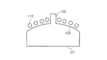
- the uniformity of the thickness of the molten material in the width direction D1 of the discharge port is determined not only by the shape of the discharge port but also by the viscosity of the molten material and the shape of the flow path for sending the molten material to the discharge port. Therefore, a so-called coat hanger type die shown in FIG. 10A is known as the shape of the flow path that improves the uniformity of the molten material discharged from the discharge port.
- the edge 120 of the coat hanger die flow channel connected to the melted material flow channel 106 is formed as a curved surface that gradually spreads and curves in a hanger shape, and is formed to be smoothly continuous with the discharge port 107. ing.
- the thickness of the molten material discharged from the discharge port may not be uniform over the width direction D1 of the discharge port.
- One of the reasons why the thickness of the molten material does not become uniform in this way is that the gap between the discharge ports is opened by the internal pressure of the flat die generated when the molten material flows in the flow path of the flat die, and the width of the discharge port In other words, the gap between the discharge ports is unevenly opened in the direction, that is, so-called opening occurs.
- This mouth opening is caused by the difference between the positions of the plurality of fastening bolts connecting the pair of main bodies and the discharge ports at the center portion and the outer edge portion of the flat die. This is caused by the difference in moment of inertia caused by the tightening force.
- a flow path shape for preventing such a difference in moment of inertia a flow path of a straight manifold die shown in FIG. 10B is known.
- the distance between each fastening bolt 110 of the die body and the slit-like discharge port 107 is made equal at each position in the width direction of the discharge port 107, thereby opening the mouth over the width direction of the discharge port. The amount uniformity is enhanced.
- a flat die having an adjustment mechanism for correcting an uneven opening amount in the width direction of the discharge port by applying a pressing force to the lip portion constituting the discharge port with respect to the opening amount has been proposed.
- a plurality of adjusting mechanisms are arranged along the width direction D1 of the discharge port, and the opening amount is adjusted by adjusting the adjusting mechanism arranged at a position where the opening amount is relatively large. Correct small.
- the opening amount in the width direction D1 of the discharge port is made uniform, and the molten material discharged from the discharge port can be discharged in a uniform thickness over the width direction D1 of the discharge port.
- a pair of side plates 111 is formed on each side surface 108 of the flat die 101 in order to seal the grooves 109 communicating with both end portions in the width direction D1 of the discharge port 107. Is fixed.
- Such a side plate 111 constrains both ends in the width direction D1 of the discharge port 107, and the die body 105 with respect to a direction (hereinafter referred to as a mouth opening direction) for opening and closing a gap at both ends of the discharge port 107. Therefore, the amount of opening at both ends of the discharge port 105 tends to be small.
- the adjustment mechanisms arranged at both ends in the width direction of the discharge port are affected by the side plate that regulates the displacement of the die body with respect to the opening direction of the discharge port. receive. For this reason, when the adjustment mechanism arrange
- this invention provides the flat die for extrusion molding which can equalize the opening amount in the longitudinal direction of a discharge outlet, and can improve the uniformity of the thickness of the film in the width direction of a film, and a film forming method. Objective.
- the flat die for extrusion molding according to the present invention is provided on each of the side surfaces and a slit-like discharge port that discharges the molten material, two side surfaces that intersect the longitudinal direction of the discharge port, respectively. And a die body having a groove communicating with both ends in the longitudinal direction of the discharge port.
- the present invention includes a sealing mechanism that is provided on each side surface of the die body and seals the groove so that the gap of the groove is variable in the gap direction orthogonal to the longitudinal direction of the groove.
- the sealing mechanism includes a sealing member that is disposed along the groove to close the groove, a pressing unit that presses the sealing member against the side surface, and a pair of first and second members that support the pressing unit and are fixed to the side surface. And a support member.
- the first support member is fixed to one end side of the side surface in the gap direction, and the second support member is fixed to the other end side of the side surface in the gap direction.
- the groove on the side surface of the die body is sealed by the sealing mechanism so that the gap can be changed in the gap direction.
- the sealing member keeps the groove sealed.
- the edge in the gap direction of the groove slides in the gap direction with respect to the sealing member.
- the first and second support members slide relative to the pressing means that presses the sealing member against the side surfaces, and are displaced independently with respect to the gap direction of the groove.
- the film forming method according to the present invention includes a step of discharging a molten material using the flat die for extrusion molding and a step of forming a film with the molten material discharged from the flat die for extrusion molding.
- the opening amount can be made uniform over the longitudinal direction of the discharge port, and the uniformity of the thickness of the film in the width direction of the film can be improved.
- FIG. 2 is a cross-sectional view showing the sealing mechanism provided in the flat die of the present embodiment along the line AA in FIG. 1. It is a side view which shows the sealing mechanism with which the flat die of this embodiment is provided.
- the flat die of this embodiment it is a figure which shows the relative opening amount with respect to the position in the width direction of a discharge outlet.
- it is a schematic diagram which shows the structural example of the positioning convex part for positioning a sealing member.
- FIG. 7 is a cross-sectional view showing a main part of a conventional flat die along the line BB in FIG. 6. It is sectional drawing which shows typically the flow path of the conventional coat hanger type die. It is sectional drawing which shows typically the flow path of the conventional straight manifold type
- FIG. 1 shows a schematic perspective view of the flat die of the present embodiment.
- dye of this embodiment is shown.
- the flat die 1 of the present embodiment is attached to an extruder that extrudes a molten resin material as a molten material, and is used for discharging the resin material into a film shape.
- the flat die 1 of this embodiment includes a slit-like discharge port 7 that discharges a molten material in a film shape, and two side surfaces 8 that are orthogonal to the width direction D1 of the discharge port 7.
- the die body 5 is provided on each side surface 8 and having grooves 9 communicating with both ends of the discharge port 7 in the width direction D1.
- the flat die 1 of the present embodiment is provided on each side surface 8 of the die body 5, and the groove 9 has a groove 9 in which the gap of the groove 9 can be varied in the gap direction S perpendicular to the width direction D1 of the discharge port 7.
- a sealing mechanism 11 for sealing 9 is provided.
- the die main body 5 is configured by combining a pair of main bodies 5 a and 5 b and integrally connecting them using a plurality of fastening bolts 10.
- a flow path 6 through which the molten resin material flows is formed inside the die body 5, and a discharge port 7 is formed downstream of the flow path 6.
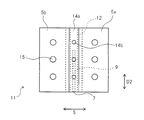
- FIG. 3 shows a plan view of the seal mechanism 11 provided in the flat die 1 of the present embodiment.
- FIG. 4 the side view of the sealing mechanism 11 with which the flat die 1 of this embodiment is provided is shown.
- the seal mechanism 11 includes a sealing member 12 that is disposed along the groove 9 to close the groove 9, and a pressing member 14 that serves as a pressing unit that presses the sealing member 12 against the side surface 8. And a pair of first and second support members 13 a and 13 b that support the pressing member 14 and are fixed to the side surface 8.
- the first support member 13 a is fixed to one end side of the side surface 8 with respect to the gap direction S of the groove 9, and the second support member 13 b is the other end of the side surface 8 with respect to the gap direction S of the groove 9. It is fixed on the side.
- the sealing member 12 is formed in a long shape extending in the longitudinal direction D ⁇ b> 2 of the groove 9.
- the pressing member 14 includes a guide member 14 a that contacts the sealing member 12 to guide the position of the sealing member 12 with respect to the groove 9, and a guide member that has one end abutting the sealing member 12. 14a, and a plurality of pressing screws 14b that press the sealing member 12 against the side surface 8 of the die body 5.
- the first support member 13 a is in contact with one end side in the gap direction S of the groove 9 and the second support member 13 b is in contact with the other end side in the gap direction S of the groove 9. .
- the guide member 14 a has a cross-section [formed in a letter shape, and has a guide concave portion 17 as a guide portion for guiding the position of the sealing member 12 with respect to the groove 9.
- the guide member 14a is disposed along the longitudinal direction D2 of the sealing member 12 so as to cover the sealing member 12.
- the pressing screw 14 b is disposed on the guide member 14 a with a predetermined interval along the longitudinal direction D ⁇ b> 2 of the groove 9.
- the guide member 14a is provided with a screw hole into which the pressing screw 14b is screwed.
- the head of the pressing screw 14b protrudes to the outside through a gap where the first support member 13a and the second support member 13b face each other, and the first and second support members 13a and 13b are fixed to the side surface 8. In this state, the screwing amount of the pressing screw 14b can be adjusted.
- each of the first and second support members 13a and 13b is provided with a concave portion 18 as a guide portion for guiding the guide member 14a on a surface that is in contact with the side surface 8 of the die body 5.
- the guide member 14a engages with the recess 18 of each of the first and second support members 13a and 13b, so that movement when the pressing screw 14b is screwed in is restricted.
- the first support member 13 a is provided on one end side in the gap direction S of the groove 9 in the guide member 14 a in a state where the seal mechanism 11 is fixed to the side surface 8 of the die body 5.
- the contact is made so as to restrict the movement of the guide member 14a relative to the axial direction of the pressing screw 14b (relative to the direction away from the sealing member 12).
- the second support member 13b is in contact with the guide member 14a on the other end side in the gap direction S of the groove 9 so as to restrict the movement of the guide member 14a with respect to the axial direction of the pressing screw 14b. Yes.
- the pressing screw 14b since the pressing screw 14b is engaged with the screw hole of the guide member 14a, one end of the pressing screw 14b comes into contact with the sealing member 12 by being screwed in by a predetermined screwing amount. By further screwing the pressing screw 14b, one end of the pressing screw 14b presses the sealing member 12 against the side surface 8, and the reaction force from the sealing member 12 is received by the guide member 14a. At this time, the movement of the pressing screw 14b in the axial direction of the guide member 14a is restricted by the concave portions 18 of the first and second support members 13a and 13b, so that the pressing screw 14b fixed to the guide member 14a The sealing member 12 is pressed against the side surface 8 by one end. Further, by adjusting the screwing amount of the pressing screw 14b as necessary, the pressing state of the sealing member 12 against the side surface 8 can be finely adjusted, and the sealing for sealing the groove 9 using the sealing member 12 is possible. The reliability of the stopped state can be increased.
- the seal mechanism 11 has a plurality of fixing screws 15 for fixing the first and second support members 13 a and 13 b to the side surface 8.
- the fixing screw 15 is disposed on the first and second support members 13a and 13b at a predetermined interval along the longitudinal direction D2 of the groove 9, and the first and second support members 13a and 13b are attached to the first and second support members 13a and 13b. It penetrates and is fixed to the side surface 8.
- the sealing mechanism 11 in the present embodiment is configured such that the sealing member 12 is pressed against the side surface 8 by the first and second support members 13a and 13b via the guide member 14a and the pressing screw 14b.
- the sealing member 12 may be configured to be pressed directly against the side surface 8 of the die body 5 by the first and second support members 13a and 13b.
- an urging member such as a leaf spring for pressing the sealing member 12 is provided in each concave portion 18 of the first and second support members 13a and 13b. May be.
- the groove 9 on the side surface 8 of the die body 5 is sealed by the seal mechanism 11 so as to be displaceable in the gap direction S. For this reason, when a force larger than the pressing force with which the guide member 14 a and the pressing screw 14 b press the sealing member 12 against the side surface 8 of the die body 5 acts on the gap direction S of the groove 9, the sealing member 12. However, the edge in the gap direction S of the groove 9 slides in the gap direction S with respect to the sealing member 12 while maintaining the state in which the groove 9 is sealed. At this time, the first and second support members 13 a and 13 b slide relative to the guide member 14 a that presses the sealing member 12 against the side surface 8, and are independently displaced with respect to the gap direction S of the groove 9. To do.
- both end portions in the width direction D ⁇ b> 1 of the discharge port 7 are restrained by the first and second support members 13 a and 13 b fixed to the side surface 8. Not. Accordingly, since the displacement of the die body 5 with respect to the direction in which the gap of the groove 9 is opened is not restricted, both end portions in the width direction D1 of the discharge port 7 are displaced in the direction in which the opening amount D of the discharge port 7 shown in FIG. Is not regulated. Thereby, since the change of the opening amount D at both ends in the width direction D1 of the discharge port 7 is not hindered, the opening amount D can be made uniform over the width direction D1 of the discharge port 7.
- the sealing member 12 sealing the groove 9
- the sealing member 12 is pressed against the side surface 8 by the pressing screw 14b screwed into the screw hole of the guide member 14a.
- the reaction force acting on the guide member 14a is received by the first and second support members 13a and 13b from the sealing member 12 pressed against the side surface 8 by the pressing screw 14b.
- the film forming method using the flat die 1 of the present embodiment includes a discharge step of discharging the molten material using the flat die 1 and a forming step of forming a film with the molten material discharged from the flat die 1 in the discharge step. And have.
- a resin material discharged from the discharge port 7 of the flat die 1 is sandwiched between a pair of molding rolls and molded into a film shape.
- FIG. 5 shows the amount of opening relative to the position of the discharge port 7 in the width direction D1 in the flat die 1 of the present embodiment.
- the vertical axis indicates the relative opening amount with reference to the center opening amount D in the width direction D1 of the discharge port 7
- the horizontal axis indicates the position of the discharge port 7 in the width direction D1 [ m].
- the flat die 1 of this embodiment is shown by the continuous line L1
- the flat die of a comparative form is shown by the broken line L2.
- the flat die of the comparative form has a configuration in which the side plate 111 is fixed across the groove 109 of the die main body 105, similarly to the configuration shown in FIGS.
- the relative opening amount indicates a relative value of the opening amount when the central opening amount D in the width direction D1 of the discharge port 107 of the flat die of the comparative form is “1”.
- the flat die of the comparative form has a smaller amount of relative opening as it approaches the end from the center in the width direction D ⁇ b> 1 of the discharge port 107.
- the relative opening amount sharply decreases as the distance from the end of the discharge port 107 approaches 1.5m, and the relative opening amount at the end of the discharge port 107 in the width direction D1.
- the flat die 1 of the embodiment in the width direction D1 of the discharge port 7, it is eliminated that the relative opening amount suddenly decreases, and gradually decreases from a position 1.5 m from the end toward the end. Yes.
- the first and second support members 13a and 13b are disposed on the side surfaces while the sealing member 12 keeps the groove 9 sealed. 8 can be displaced independently of the gap direction S of the groove 9.
- the opening amount D can be made uniform over the width direction D1 of the discharge port 7.
- the opening amount D can be made uniform over the width direction D1 of the discharge port 7, and the uniformity of the film thickness in the width direction of the film can be improved.
- the flat die for extrusion molding according to the present invention can be suitably applied to a flat die having an adjustment mechanism for adjusting the opening amount D of the discharge port. Since both end portions in the width direction D1 of the discharge port are not restrained by the seal mechanism 11, the opening amount D can be adjusted with high accuracy without hindering the adjustment of the opening amount D of the discharge port by the adjusting mechanism. Become.
- the opening amount D at both ends in the width direction D1 of the discharge port 7 is ensured to be large, and the opening amount D is adjusted with high accuracy by using the adjustment mechanism described above. Therefore, the range of the viscosity of the resin material applicable to the flat die 1 can be widened, and it is possible to sufficiently cope with fluctuations in film manufacturing conditions. That is, according to the present embodiment, the film production conditions that can be dealt with are widened, and the versatility of the flat die can be enhanced, which can contribute to the improvement of film productivity.
- the sealing mechanism 11 in the present embodiment is configured to press the sealing member 12 against the side surface 8 of the die body 5 by the guide member 14a and the pressing screw 14b.
- a coil spring, a leaf spring, or the like can be attached as necessary. You may be comprised so that the sealing member 12 may be pressed via a biasing member. In this case, the biasing member is disposed between the id member 14 a and the sealing member 12. By using the urging member, the reliability of sealing the groove 9 by the sealing member 12 can be enhanced.
- a positioning concave portion or a positioning convex portion may be formed on the side surface 8 of the die body 5 as positioning means for positioning the position of the sealing member 12 with respect to the groove 9.
- 6A and 6B are schematic views of configuration examples of positioning concave portions and positioning convex portions for positioning the sealing member 12.
- the positioning recess 21 is formed on the side surface 8 along the groove 9, and the sealing member 12 is disposed in the positioning recess 21 to seal against the groove 9.
- the member 12 can be easily positioned.
- the positioning convex portion 22 is provided on the side surface 8 along the groove 9, for example, and the positioning convex portion 22 is notched to the outer peripheral portion of the sealing member 12.
- the positioning recess 21 and the positioning protrusion 22 are formed so as not to hinder the displacement of the die body 5 with respect to the gap direction S of the groove 9, that is, the displacement of the die body 5 with respect to the opening / closing direction of the discharge port 7.
- the positioning convex portion 22 engages with the engaging concave portion 12a. For this reason, when the first and second support members 13a and 13b are removed from the die body 5 for maintenance, the guide member 14a and the sealing member 12 can be prevented from falling.
- the through hole 13c that penetrates the second support member 13b in the longitudinal direction D1 of the discharge port and the penetration that penetrates the guide member 14a in the longitudinal direction D1 of the discharge port coaxially with the through hole 13c.
- FIG. The hole 12b may penetrate the sealing member 12 in the longitudinal direction D1 of the discharge port, or may terminate in the middle.
- the pin 19 is passed through the through hole 13c, the through hole 14c, and the hole 12b.
- the first support member 13 a is removed from the die body 5, and then the second support member 13 b is removed from the die body 5. Since the pin 19 inserted into the through hole 13c of the second support member 13b holds the guide member 14a and the sealing member 12, the guide member 14a and the sealing member 12 can be prevented from falling.
- the through hole 13c may be provided in the first support member 13a, or may be provided in both the first support member 13a and the second support member 13b. Even in the embodiment in which the guide member 14a is not provided, the same effect can be obtained by passing the pin 19 through the through hole 13c of the second support member 13b and the hole 12b of the sealing member 12.
- the flat die for extrusion molding according to the present invention is not limited to a configuration including a die main body formed by combining a pair of main bodies.
- a groove on the side surface intersecting the width direction of the discharge port so as to communicate with the discharge port, and the groove is formed on the side surface of the die body.
- the provided structure may be applied to a die body formed by combining three or more bodies or a die body formed integrally.
Landscapes
- Engineering & Computer Science (AREA)
- Mechanical Engineering (AREA)
- Manufacturing & Machinery (AREA)
- Extrusion Moulding Of Plastics Or The Like (AREA)
Abstract
Description
5 ダイ本体
7 吐出口
8 側面
9 溝
11 シール機構
12 封止部材
13a 第1の支持部材
13b 第2の支持部材
14 押圧部材
14a ガイド部材
14b 押圧ネジ
15 固定ネジ
D1 吐出口の幅方向
D2 溝の幅方向
S 間隙方向
Claims (6)
- 溶融材料を吐出するスリット状の吐出口と、前記吐出口の長手方向に交差する2つの側面と、各前記側面にそれぞれ設けられ、前記吐出口の前記長手方向における両端に連通する溝と、を有するダイ本体と、
前記ダイ本体の各前記側面にそれぞれ設けられ、前記溝の長手方向に直交する間隙方向に前記溝の間隙が変動可能に前記溝を封止するシール機構と、を備え、
前記シール機構は、前記溝に沿って配置されて前記溝を塞ぐ封止部材と、前記封止部材を前記側面に押圧させる押圧手段と、前記押圧手段を支持して前記側面に固定される一対の第1及び第2の支持部材と、を有し、前記第1の支持部材が、前記間隙方向における前記側面の一端側に固定されると共に、前記第2の支持部材が、前記間隙方向における前記側面の他端側に固定されている、押出成形用フラットダイ。 - 前記押圧手段は、前記封止部材に当接して前記溝に対する前記封止部材の位置を案内するガイド部材と、
一端が前記封止部材に当接するように前記ガイド部材にねじ込まれて設けられ、前記側面に対して前記封止部材を押圧する押圧ネジと、を有し、
前記ガイド部材には、前記間隙方向における一端側に前記第1の支持部材が、前記押圧ネジの軸方向に対する前記ガイド部材の移動を規制するように当接され、前記間隙方向における他端側に前記第2の支持部材が、前記押圧ネジの軸方向に対する前記ガイド部材の移動を規制するように当接されている、請求項1に記載の押出成形用フラットダイ。 - 前記第1及び第2の支持部材には、前記ガイド部材の位置を案内するガイド部が設けられている、請求項2に記載の押出成形用フラットダイ。
- 前記ダイ本体の前記側面には、前記溝に対して前記封止部材を位置決めするための位置決め手段が設けられている、請求項1ないし3のいずれか1項に記載の押出成形用フラットダイ。
- 前記第1の支持部材と前記第2の支持部材の少なくともいずれかを前記吐出口の前記長手方向に貫通する貫通孔と、前記封止部材を前記貫通孔と同軸に前記吐出口の前記長手方向に延びる穴と、前記貫通孔と前記穴とに通されたピンと、を有している、請求項1ないし4のいずれか1項に記載の押出成形用フラットダイ。
- 請求項1ないし5のいずれか1項に記載の押出成形用フラットダイを用いて溶融材料を吐出する工程と、前記押出成形用フラットダイから吐出された溶融材料によってフィルムを成形する工程と、を有するフィルム成形方法。
Priority Applications (3)
| Application Number | Priority Date | Filing Date | Title |
|---|---|---|---|
| KR1020177000356A KR102308263B1 (ko) | 2014-07-25 | 2015-07-09 | 압출 성형용 플랫 다이 및 필름 성형 방법 |
| CN201580040446.XA CN106536153B (zh) | 2014-07-25 | 2015-07-09 | 挤出成形用平模以及薄膜成形方法 |
| JP2015551655A JP6019251B2 (ja) | 2014-07-25 | 2015-07-09 | 押出成形用フラットダイ及びフィルム成形方法 |
Applications Claiming Priority (2)
| Application Number | Priority Date | Filing Date | Title |
|---|---|---|---|
| JP2014151550 | 2014-07-25 | ||
| JP2014-151550 | 2014-07-25 |
Publications (1)
| Publication Number | Publication Date |
|---|---|
| WO2016013408A1 true WO2016013408A1 (ja) | 2016-01-28 |
Family
ID=55162937
Family Applications (1)
| Application Number | Title | Priority Date | Filing Date |
|---|---|---|---|
| PCT/JP2015/069789 Ceased WO2016013408A1 (ja) | 2014-07-25 | 2015-07-09 | 押出成形用フラットダイ及びフィルム成形方法 |
Country Status (4)
| Country | Link |
|---|---|
| JP (1) | JP6019251B2 (ja) |
| KR (1) | KR102308263B1 (ja) |
| CN (1) | CN106536153B (ja) |
| WO (1) | WO2016013408A1 (ja) |
Cited By (2)
| Publication number | Priority date | Publication date | Assignee | Title |
|---|---|---|---|---|
| JP2018059232A (ja) * | 2016-10-04 | 2018-04-12 | 日本ノズル株式会社 | 樹脂分配金型 |
| JP2024004571A (ja) * | 2022-06-29 | 2024-01-17 | 東レ株式会社 | シート成形口金 |
Families Citing this family (2)
| Publication number | Priority date | Publication date | Assignee | Title |
|---|---|---|---|---|
| JP3338044B1 (ja) | 2001-12-04 | 2002-10-28 | 株式会社マルヒ | 櫛歯ベッド装置および櫛歯ベッドシステム |
| JP7284665B2 (ja) * | 2018-11-09 | 2023-05-31 | 芝浦機械株式会社 | Tダイ、tダイ用パッキン、側方密閉機構、およびシート・フィルム製造装置 |
Citations (4)
| Publication number | Priority date | Publication date | Assignee | Title |
|---|---|---|---|---|
| JPS6067129A (ja) * | 1983-09-26 | 1985-04-17 | Toray Ind Inc | スリット間隙調整装置を備えた口金 |
| JPH06198707A (ja) * | 1992-12-29 | 1994-07-19 | Kuraray Co Ltd | 可動式アウターデッケル |
| JP2002187190A (ja) * | 2000-10-11 | 2002-07-02 | Toray Ind Inc | シートの製造方法および口金スリット間隙プロファイルの測定装置 |
| JP2005289025A (ja) * | 2004-04-05 | 2005-10-20 | Akira Shimizu | フィルム成形用tダイ |
Family Cites Families (7)
| Publication number | Priority date | Publication date | Assignee | Title |
|---|---|---|---|---|
| IT1288475B1 (it) * | 1996-05-03 | 1998-09-22 | Carraro Snc | Dispositivo di regolazione della distanza di separazione tra i labbri di una testa di estrusione per laminati termoplastici |
| EP2113362A1 (en) * | 2008-04-24 | 2009-11-04 | Tonen Chemical Corporation | Coextrusion die and manifold system therefor |
| JP5501794B2 (ja) * | 2010-02-23 | 2014-05-28 | 株式会社日本製鋼所 | 押出成形用フラットダイ |
| JP5204147B2 (ja) | 2010-04-08 | 2013-06-05 | 株式会社日本製鋼所 | 押出成形用フラットダイ |
| US8752501B2 (en) * | 2010-07-29 | 2014-06-17 | Corning Incorporated | Systems and methods for dispensing a fluid |
| JP5430626B2 (ja) | 2011-09-02 | 2014-03-05 | 株式会社日本製鋼所 | ダイリップ調整装置 |
| CN103213266B (zh) * | 2013-04-28 | 2015-11-18 | 广东达诚机械有限公司 | 平肩式塑料挤出平模头 |
-
2015
- 2015-07-09 CN CN201580040446.XA patent/CN106536153B/zh active Active
- 2015-07-09 WO PCT/JP2015/069789 patent/WO2016013408A1/ja not_active Ceased
- 2015-07-09 JP JP2015551655A patent/JP6019251B2/ja active Active
- 2015-07-09 KR KR1020177000356A patent/KR102308263B1/ko active Active
Patent Citations (4)
| Publication number | Priority date | Publication date | Assignee | Title |
|---|---|---|---|---|
| JPS6067129A (ja) * | 1983-09-26 | 1985-04-17 | Toray Ind Inc | スリット間隙調整装置を備えた口金 |
| JPH06198707A (ja) * | 1992-12-29 | 1994-07-19 | Kuraray Co Ltd | 可動式アウターデッケル |
| JP2002187190A (ja) * | 2000-10-11 | 2002-07-02 | Toray Ind Inc | シートの製造方法および口金スリット間隙プロファイルの測定装置 |
| JP2005289025A (ja) * | 2004-04-05 | 2005-10-20 | Akira Shimizu | フィルム成形用tダイ |
Cited By (3)
| Publication number | Priority date | Publication date | Assignee | Title |
|---|---|---|---|---|
| JP2018059232A (ja) * | 2016-10-04 | 2018-04-12 | 日本ノズル株式会社 | 樹脂分配金型 |
| JP2024004571A (ja) * | 2022-06-29 | 2024-01-17 | 東レ株式会社 | シート成形口金 |
| JP7779208B2 (ja) | 2022-06-29 | 2025-12-03 | 東レ株式会社 | シート成形口金 |
Also Published As
| Publication number | Publication date |
|---|---|
| JP6019251B2 (ja) | 2016-11-02 |
| KR102308263B1 (ko) | 2021-10-01 |
| JPWO2016013408A1 (ja) | 2017-04-27 |
| KR20170035884A (ko) | 2017-03-31 |
| CN106536153B (zh) | 2018-05-29 |
| CN106536153A (zh) | 2017-03-22 |
Similar Documents
| Publication | Publication Date | Title |
|---|---|---|
| JP6019251B2 (ja) | 押出成形用フラットダイ及びフィルム成形方法 | |
| US4695236A (en) | Apparatus for continuous extrusion of a multilayer synthetic resin web | |
| US8123511B2 (en) | Decoupled transverse flow metering gap and lip gap | |
| JP2798687B2 (ja) | ローラ・ヘッド装置 | |
| US8092207B2 (en) | Decoupled transverse flow metering gap and lip gap | |
| US9815237B2 (en) | System for adjusting the land channel length on an extrusion die | |
| EP2960042B1 (en) | Varying transition zone manifold | |
| JP2008178818A (ja) | スリットダイ及びシム | |
| EP0484841B1 (de) | Extrusionsdüse zur Herstellung flacher Bahnen aus thermoplastischem Kunststoff | |
| CN111215293B (zh) | 涂布机用狭缝式涂布模头 | |
| JP7284665B2 (ja) | Tダイ、tダイ用パッキン、側方密閉機構、およびシート・フィルム製造装置 | |
| US3057010A (en) | Elongated slit nozzle | |
| US10828818B2 (en) | Sheet extrusion die | |
| JP5204147B2 (ja) | 押出成形用フラットダイ | |
| DE502004007806D1 (de) | Manteln mehrerer kabelleiter | |
| EP1660299B1 (en) | Extrusion die with internal deckle system | |
| UA117132C2 (uk) | Фільєра для виготовлення плівки шляхом екструзії | |
| JP3660085B2 (ja) | ディッケル付tダイ | |
| CN204749205U (zh) | 一种夹心包装带复合模头 | |
| KR101694479B1 (ko) | 코팅용 t-다이스의 양립식 일체형 고정구조 | |
| JP2018126893A (ja) | 押出製膜用ダイヘッド | |
| JP2019048408A (ja) | ゴム押出装置およびゴム押出物の製造方法 | |
| UA12383U (en) | Flat-slotted extrusion head |
Legal Events
| Date | Code | Title | Description |
|---|---|---|---|
| ENP | Entry into the national phase |
Ref document number: 2015551655 Country of ref document: JP Kind code of ref document: A |
|
| 121 | Ep: the epo has been informed by wipo that ep was designated in this application |
Ref document number: 15823974 Country of ref document: EP Kind code of ref document: A1 |
|
| ENP | Entry into the national phase |
Ref document number: 20177000356 Country of ref document: KR Kind code of ref document: A |
|
| NENP | Non-entry into the national phase |
Ref country code: DE |
|
| 122 | Ep: pct application non-entry in european phase |
Ref document number: 15823974 Country of ref document: EP Kind code of ref document: A1 |