WO2016013321A1 - 燃料電池のアノードシステム - Google Patents
燃料電池のアノードシステム Download PDFInfo
- Publication number
- WO2016013321A1 WO2016013321A1 PCT/JP2015/066915 JP2015066915W WO2016013321A1 WO 2016013321 A1 WO2016013321 A1 WO 2016013321A1 JP 2015066915 W JP2015066915 W JP 2015066915W WO 2016013321 A1 WO2016013321 A1 WO 2016013321A1
- Authority
- WO
- WIPO (PCT)
- Prior art keywords
- gas
- fuel cell
- anode
- liquid separator
- anode system
- Prior art date
- Legal status (The legal status is an assumption and is not a legal conclusion. Google has not performed a legal analysis and makes no representation as to the accuracy of the status listed.)
- Ceased
Links
Images


Classifications
-
- B—PERFORMING OPERATIONS; TRANSPORTING
- B60—VEHICLES IN GENERAL
- B60L—PROPULSION OF ELECTRICALLY-PROPELLED VEHICLES; SUPPLYING ELECTRIC POWER FOR AUXILIARY EQUIPMENT OF ELECTRICALLY-PROPELLED VEHICLES; ELECTRODYNAMIC BRAKE SYSTEMS FOR VEHICLES IN GENERAL; MAGNETIC SUSPENSION OR LEVITATION FOR VEHICLES; MONITORING OPERATING VARIABLES OF ELECTRICALLY-PROPELLED VEHICLES; ELECTRIC SAFETY DEVICES FOR ELECTRICALLY-PROPELLED VEHICLES
- B60L50/00—Electric propulsion with power supplied within the vehicle
- B60L50/50—Electric propulsion with power supplied within the vehicle using propulsion power supplied by batteries or fuel cells
- B60L50/70—Electric propulsion with power supplied within the vehicle using propulsion power supplied by batteries or fuel cells using power supplied by fuel cells
-
- H—ELECTRICITY
- H01—ELECTRIC ELEMENTS
- H01M—PROCESSES OR MEANS, e.g. BATTERIES, FOR THE DIRECT CONVERSION OF CHEMICAL ENERGY INTO ELECTRICAL ENERGY
- H01M8/00—Fuel cells; Manufacture thereof
- H01M8/04—Auxiliary arrangements, e.g. for control of pressure or for circulation of fluids
-
- Y—GENERAL TAGGING OF NEW TECHNOLOGICAL DEVELOPMENTS; GENERAL TAGGING OF CROSS-SECTIONAL TECHNOLOGIES SPANNING OVER SEVERAL SECTIONS OF THE IPC; TECHNICAL SUBJECTS COVERED BY FORMER USPC CROSS-REFERENCE ART COLLECTIONS [XRACs] AND DIGESTS
- Y02—TECHNOLOGIES OR APPLICATIONS FOR MITIGATION OR ADAPTATION AGAINST CLIMATE CHANGE
- Y02E—REDUCTION OF GREENHOUSE GAS [GHG] EMISSIONS, RELATED TO ENERGY GENERATION, TRANSMISSION OR DISTRIBUTION
- Y02E60/00—Enabling technologies; Technologies with a potential or indirect contribution to GHG emissions mitigation
- Y02E60/30—Hydrogen technology
- Y02E60/50—Fuel cells
-
- Y—GENERAL TAGGING OF NEW TECHNOLOGICAL DEVELOPMENTS; GENERAL TAGGING OF CROSS-SECTIONAL TECHNOLOGIES SPANNING OVER SEVERAL SECTIONS OF THE IPC; TECHNICAL SUBJECTS COVERED BY FORMER USPC CROSS-REFERENCE ART COLLECTIONS [XRACs] AND DIGESTS
- Y02—TECHNOLOGIES OR APPLICATIONS FOR MITIGATION OR ADAPTATION AGAINST CLIMATE CHANGE
- Y02T—CLIMATE CHANGE MITIGATION TECHNOLOGIES RELATED TO TRANSPORTATION
- Y02T90/00—Enabling technologies or technologies with a potential or indirect contribution to GHG emissions mitigation
- Y02T90/40—Application of hydrogen technology to transportation, e.g. using fuel cells
Definitions
- the present invention relates to an anode system for a fuel cell.
- DE 102012016976A1 is a fuel in which a gas-liquid separator is installed in an anode-side circulation circuit, which is a circulation circuit for circulating the gas discharged from the anode-side outlet, and a heat exchanger is provided in the liquid region in the gas-liquid separator.
- a battery system is disclosed.
- the present invention has been made in view of the above, and can improve passage blockage due to freezing that occurs in a passage in a predetermined low temperature portion of the anode-side circulation circuit when the operation of the fuel cell is started in a low temperature environment.
- An object is to provide an anode system for a fuel cell.
- An anode system of a fuel cell includes a fuel cell that generates power by receiving supply of an anode gas and a cathode gas, and gas discharged from an anode electrode side outlet of the fuel cell on the anode electrode side of the fuel cell.
- a circulation circuit that is introduced into the inlet; and a gas-liquid separator that is provided in the circulation circuit and separates a liquid component contained in the gas from the gas discharged from the anode electrode side outlet.
- the said gas-liquid separator is provided with the holding
- FIG. 1 is a schematic configuration diagram of an anode system according to the first embodiment.
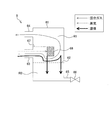
- FIG. 2 is a schematic configuration diagram of a gas-liquid separator provided in the anode system of the first embodiment.
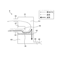
- FIG. 3 is a schematic configuration diagram of a gas-liquid separator provided in the anode system of the second embodiment.
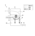
- FIG. 4 is a schematic configuration diagram of a gas-liquid separator provided in the anode system of the third embodiment.
- FIG. 5 is a schematic configuration diagram of an anode system according to a fourth embodiment.
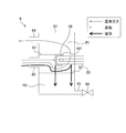
- FIG. 6 is a schematic configuration diagram of a gas-liquid separator provided in the anode system of the fourth embodiment.
- the fuel cell has a structure in which an electrolyte membrane is sandwiched between an anode electrode that is a fuel electrode and a cathode electrode that is an oxidant electrode.
- the fuel cell generates power by supplying an anode gas containing hydrogen as a fuel gas to the anode electrode and a cathode gas containing oxygen as an oxidant gas to the cathode electrode.
- the electrode reaction that proceeds in both the anode electrode and the cathode electrode is as follows.
- Anode electrode 2H 2 ⁇ 4H + + 4e ⁇ (1)
- Cathode electrode 4H + + 4e ⁇ + O 2 ⁇ 2H 2 O (2)
- the fuel cell generates an electromotive force of about 1 volt by the electrode reactions (1) and (2).
- the fuel cell When such a fuel cell is used as a power source for automobiles, a large amount of electric power is required. Therefore, in this case, the fuel cell is used as a fuel cell stack in which several hundred fuel cells are stacked. Then, a fuel cell system that supplies anode gas and cathode gas to the fuel cell stack is configured, and electric power for driving the vehicle is taken out.
- anode system constituting the gas distribution system on the anode electrode side of the fuel cell stack in the fuel cell system as described above.
- the anode system of the fuel cell is simply referred to as an anode system.
- FIG. 1 is a schematic configuration diagram of an anode system 1 according to the first embodiment.
- the anode system 1 includes a fuel cell stack 100.
- the fuel cell stack 100 is a stacked battery in which a plurality of fuel cells are stacked, and generates power upon receiving supply of anode gas and cathode gas. Then, the generated electric power is supplied to various electrical components such as a vehicle drive motor.
- the anode system 1 includes a high-pressure tank 2, a supply passage 3, a pressure regulating valve 4, a discharge passage 5, a gas-liquid separator 6, a reflux passage 7, a jet pump 8, and a heating unit. 9, a valve 10, and a controller 50.
- the high-pressure tank 2 stores the anode gas supplied to the fuel cell stack 100 in a high-pressure state.
- the supply passage 3 is a passage through which anode gas supplied to the fuel cell stack 100 flows.
- the supply passage 3 has one end connected to the high-pressure tank 2 and the other end connected to the anode-side inlet 110 of the fuel cell stack 100.
- the pressure regulating valve 4 is provided in the supply passage 3.
- the pressure regulating valve 4 adjusts the pressure of the anode gas flowing out from the high-pressure tank 2 to the supply passage 3 to a desired pressure.
- the discharge passage 5 is a passage through which the anode off gas discharged from the fuel cell stack 100 flows.
- the discharge passage 5 has one end connected to the anode electrode-side outlet 120 of the fuel cell stack 100 and the other end connected to the gas-liquid separator 6.
- the anode off gas is a mixed gas of excess anode gas that has not been used in the electrode reaction and an inert gas such as nitrogen leaking from the cathode side.
- the anode off gas contains moisture generated during the power generation process.
- the gas-liquid separator 6 separates moisture contained in the anode off-gas from the gas discharged from the anode electrode side outlet 120, that is, the anode off-gas.
- the reflux passage 7 is a passage for returning the anode off gas to the supply passage 3.
- the reflux passage 7 has one end connected to the gas-liquid separator 6 and the other end connected to the jet pump 8. Specifically, the reflux passage 7 is connected to a negative pressure generating portion of the jet pump 8.
- the jet pump 8 is provided in the supply passage 3.
- the jet pump 8 is disposed downstream of the pressure regulating valve 4.
- Anode gas is supplied to the jet pump 8.
- the jet pump 8 generates a negative pressure by the flow of the supplied anode gas.
- the anode off gas is sucked by the generated negative pressure and transported to the anode electrode side inlet 110.
- the jet pump 8 sucks the gas that has passed through the gas-liquid separator 6 as the anode off gas.
- the sucked gas is transported to the anode side inlet 110 together with the anode gas supplied from the high pressure tank 2.
- a pump other than the jet pump 8 can be used for transporting the anode off gas.
- the heating unit 9 is provided in the supply passage 3.
- the heating unit 9 is disposed downstream of the pressure regulating valve 4 and upstream of the jet pump 8.
- the heating unit 9 heats the anode gas supplied to the jet pump 8.
- an explosion-proof electric heater can be used for the heating unit 9, for example, an explosion-proof electric heater can be used.
- the valve 10 is provided in the supply passage 3.
- the valve 10 is disposed between the heating unit 9 and the jet pump 8.
- the valve 10 is specifically an electromagnetic valve and includes a coil 10a.
- the coil 10 a drives the valve body of the valve 10.
- An explosion-proof specification valve is used as the valve 10.
- the controller 50 is an electronic control device and controls the pressure regulating valve 4 and the valve 10.
- the controller 50 receives a signal from the switch 55 for instructing operation and stop of the fuel cell stack 100.
- the operation of the fuel cell stack 100 is performed by supplying the anode gas and the cathode gas to the fuel cell stack 100.
- the operation of the fuel cell stack 100 is stopped by stopping the supply to the fuel cell stack 100 of at least one of the anode gas and the cathode gas.
- the anode system 1 configured as described above includes a circulation circuit 30.
- the circulation circuit 30 is an anode side circulation circuit that circulates the anode off gas by introducing the anode off gas to the anode electrode side inlet 110.
- the circulation circuit 30 includes a fuel cell stack 100, a gas-liquid separator 6, and a jet pump 8. When viewed from the fuel cell stack 100 as the starting point, the circulation circuit 30 causes the anode off gas to flow in the order of the anode electrode side outlet 120, the gas-liquid separator 6, the jet pump 8, and the anode electrode side inlet 110.
- FIG. 2 is a schematic configuration diagram of the gas-liquid separator 6 provided in the anode system 1 of the first embodiment.
- FIG. 2 also shows the flow of fluid in the gas-liquid separator 6 when the operation of the fuel cell stack 100 is started under a low temperature environment.
- a flow of a mixed gas of an anode gas and an inert gas, a flow of a vapor, and a flow of a liquid are shown as the flow of the fluid.
- the gas-liquid separator 6 includes a housing 61, a filter 62, a gas inlet 63, a gas outlet 64, a liquid outlet 65, a purge valve 66, a flow path wall portion 67, and a holding portion 68. Prepare.
- the housing 61 forms an internal space of the gas-liquid separator 6.
- An anode off-gas containing mixed gas and vapor, that is, moisture is introduced into the internal space of the gas-liquid separator 6.
- the liquid that is generated in the fuel cell stack 100 and is not vaporized is also introduced together with the anode off gas.
- the filter 62 passes through the liquid and removes foreign matters contained in the liquid.
- the filter 62 divides the internal space of the gas-liquid separator 6 up and down to divide the internal space into an upper gas region R1 and a lower liquid region R2.
- the gas region R ⁇ b> 1 is a gas region that should be secured at a minimum in the gas-liquid separator 6.
- the liquid region R ⁇ b> 2 is a liquid region that should be ensured to the maximum extent in the gas-liquid separator 6.
- the gas inlet 63, the gas outlet 64, and the liquid outlet 65 are provided in the housing 61.
- the gas inlet 63 and the gas outlet 64 open to the gas region R1, and the liquid outlet 65 opens to the liquid region R2.
- the gas outlet 64 is provided above the gas inlet 63.
- the gas inlet 63 introduces an anode off gas containing moisture into the internal space of the gas-liquid separator 6.
- the gas outlet 64 discharges the anode off gas from the gas-liquid separator 6.
- the liquid outlet 65 discharges liquid from the gas-liquid separator 6.
- the purge valve 66 is provided at the liquid outlet 65.
- the purge valve 66 performs restriction and release of the discharge of the liquid from the gas-liquid separator 6. Limiting liquid discharge includes prohibiting liquid discharge.
- the purge valve 66 can be controlled by the controller 50.
- the flow path wall 67 is provided in the housing 61.
- the flow path wall portion 67 together with the housing 61 and the filter 62 forms a gas flow path in the gas-liquid separator 6.
- the filter 62 serves as a gas flow resistance, thereby forming a gas flow path together with the housing 61 and the flow path wall portion 67.
- a gas flow path is formed through which gas flows from the gas inlet 63 to the gas outlet 64 in a U-shape.
- the flow path wall 67 is fixed to the housing 61.
- the flow path wall portion 67 may be a part of the housing 61.
- the housing 61, the filter 62, and the flow path wall portion 67 constitute a flow path forming unit that is a part of the gas-liquid separator 6 that forms a gas flow path.
- the distribution path forming unit may be regarded as a configuration that does not include the filter 62.
- a resin can be used for the distribution path forming unit.
- the holding unit 68 is a part that holds a liquid, and is provided in a gas flow path in the gas-liquid separator 6. Specifically, the holding portion 68 is provided in a portion directly above the filter 62 in the gas flow path in the gas-liquid separator 6. Specifically, the holding portion 68 is disposed at a folded portion of the gas flow path in the gas-liquid separator 6. The holding portion 68 arranged in this way is provided so as to hang down from the end portion of the flow path wall portion 67. The holding part 68 is provided in the gas region R1.
- the holding portion 68 is provided so as to at least partially face the gas inlet 63. Since the holding unit 68 is provided in this manner, it also serves as a flow inhibition unit that inhibits the flow of the gas-liquid mixed fluid.
- the holding unit 68 functions as a flow inhibition unit, thereby reducing the flow rate of the gas-liquid mixed fluid and separating the gas and the liquid by the density difference.
- the holding unit 68 holds the liquid separated from the anode off gas.
- the holding part 68 holds the liquid separated from the anode off gas by having a surface shape on which irregularities that enhance the adhesion of the liquid are formed.
- the surface shape is a surface shape in which a plurality of depressions are formed.
- the surface shape may be a surface shape formed by increasing the surface roughness, or may be a surface shape formed by providing a plurality of grooves.
- the holding portion 68 is made of metal.
- the holding part 68 may be resin.
- the holding unit 68 is configured such that the heat capacity in the holding unit 68 is larger than the heat capacity of the flow path forming unit.
- the heat capacity in the holding unit 68 is the heat capacity of the entire holding unit 68 including the liquid to be held here.
- the anode system 1 includes a fuel cell stack 100, a circulation circuit 30, and a gas-liquid separator 6.
- the gas-liquid separator 6 includes a holding unit 68.
- the liquid held by the holding unit 68 is frozen in a low temperature environment after the operation of the fuel cell stack 100 is stopped. And the frozen liquid has a high heat of fusion.
- the holding unit 68 when the operation of the fuel cell stack 100 is started in a low temperature environment, the holding unit 68 can be maintained at a lower temperature than the flow path forming unit. In addition, by maintaining the holding unit 68 at a low temperature in this way, it becomes possible to condense the moisture contained in the anode off gas by the holding unit 68. The holding unit 68 can continue the condensation of moisture until the liquid frozen by the holding unit 68 is melted and the temperature of the holding unit 68 becomes higher than the dew point of the vapor.
- the anode system 1 configured as described above, when the operation of the fuel cell stack 100 is started in a low temperature environment, the anode off-gas is cooled and included in the gas by the holding unit 68 that holds the liquid in a frozen state. It is possible to condense the liquid component. Therefore, it becomes possible to remove the liquid component from the gas. For this reason, passage blockage due to freezing that occurs in a passage in a predetermined low temperature portion of the circulation circuit 30, that is, a low temperature portion downstream from the gas-liquid separator 6 and upstream from the fuel cell stack 100 can be improved.
- the holding unit 68 is made of metal.
- the holding portion 68 can be easily lowered in a low temperature environment as compared with a resin.
- the liquid can be easily frozen by the holding portion 68.
- the holding unit 68 can be easily maintained at a low temperature.
- the frozen state of the frozen liquid can be easily maintained. For this reason, according to the anode system 1 configured as described above, when the operation of the fuel cell stack 100 is started under a low temperature environment, it is possible to easily continue the condensation of moisture in the holding unit 68.
- the holding unit 68 is configured so that the heat capacity in the holding unit 68 is larger than the heat capacity of the flow path forming unit described above. Therefore, when the operation of the fuel cell stack 100 is started in a low temperature environment, the moisture contained in the anode off gas can be efficiently condensed by the holding unit 68.
- the anode system 1 can also increase the heat capacity by configuring the holding portion 68 with metal.
- FIG. 3 is a schematic configuration diagram of the gas-liquid separator 6 provided in the anode system 1 of the second embodiment.
- the holding unit 68 is configured as described below.
- a flow blocking portion 69 is provided in the flow path wall portion 67.
- the anode system 1 of the present embodiment is configured similarly to the anode system 1 of the first embodiment.
- the holding unit 68 is a storage holding unit that holds the liquid in a stored state.
- the holding portion 68 has a saucer-like shape and is provided between the filter 62 and the gas inlet 63 in the height direction. Accordingly, the holding portion 68 is provided below the gas inlet 63.
- the holding portion 68 thus provided is further connected to the side wall portion of the housing 61 where the gas inlet 63 opens.
- the holding part 68 is provided apart from the side wall part facing the side wall part. Thereby, the liquid which the holding
- the holding portion 68 can be provided with a gap between at least one of the side wall portions of the housing 61.
- the holding unit 68 is configured such that the heat capacity of the holding unit 68 is larger than the heat capacity of the flow path forming unit.
- the heat capacity in the holding unit 68 is the heat capacity of the entire holding unit 68 including the liquid to be held, as in the case of the first embodiment.
- the distribution inhibiting part 69 is provided so as to at least partially face the gas inlet 63.
- the flow inhibition unit 69 is provided in a portion directly above the holding unit 68 in the gas flow path. Specifically, the flow inhibition unit 69 is disposed at the folded portion of the gas flow path.
- the flow inhibiting part 69 arranged in this way is provided so as to hang down from the end of the flow path wall part 67.
- the flow inhibition unit 69 inhibits the flow of the gas-liquid mixed fluid, thereby reducing the flow rate of the gas-liquid mixed fluid and separating the gas and the liquid by the density difference.
- a plate-like member can be used for the flow inhibition unit 69.
- the holding unit 68 is a storage holding unit that holds the liquid in a stored state. In this case, a large amount of liquid can be held by the holding unit 68.
- the anode system 1 of the present embodiment when the operation of the fuel cell stack 100 is started in a low temperature environment, the amount of liquid frozen in the holding unit 68 is increased, so that the moisture performed in the holding unit 68 is increased. Condensation can be continued for a long time. Therefore, the passage blockage due to freezing that occurs in the predetermined low temperature portion of the circulation circuit 30 after the low temperature start of the fuel cell stack 100 can be suitably improved by the amount of moisture condensation performed in the holding unit 68 for a long time.
- the gas-liquid separator 6 includes a housing 61, a gas inlet 63, and a flow inhibition unit 69.
- the holding unit 68 as a storage holding unit is provided below the gas inlet 63.
- the flow inhibition unit 69 is provided in a portion of the gas flow passage in the gas-liquid separator 6 immediately above the holding unit 68. According to the anode system 1 having such a configuration, the liquid can be easily stored in the holding unit 68.
- FIG. 4 is a schematic configuration diagram of the gas-liquid separator 6 provided in the anode system 1 of the third embodiment.
- the holding unit 68 is configured as described below.
- the anode system 1 of the present embodiment is configured in the same manner as the anode system 1 of the first embodiment.
- the holding unit 68 is an absorption holding unit that holds the liquid in a absorbed state.
- a holding portion 68 has a lattice-like or porous structure.
- a metal mesh structure can be applied to such a holding portion 68.
- a ceramic porous body may be applied to the holding portion 68.
- the holding unit 68 is configured such that the heat capacity of the holding unit 68 is larger than the heat capacity of the flow path forming unit.
- the heat capacity in the holding unit 68 is the heat capacity of the entire holding unit 68 including the liquid to be held, as in the case of the first embodiment.
- the holding unit 68 is an absorption holding unit that holds the liquid in a absorbed state. For this reason, according to the anode system 1 of the present embodiment, a large amount of liquid can be held by the holding portion 68 as in the case of the second embodiment. Therefore, as with the anode system 1 of the second embodiment, the passage blockage due to freezing that occurs after the fuel cell stack 100 is started at a low temperature can be suitably improved by the amount of time that the condensation of moisture performed in the holding unit 68 continues.
- the gas-liquid separator 6 includes a housing 61 and a gas inlet 63.
- maintenance part is provided so that it may oppose at least partially with the gas inlet_port
- FIG. 5 is a schematic configuration diagram of the anode system 1 of the fourth embodiment.
- the anode system 1 of the present embodiment further includes a heat medium passage 20. Further, the gas-liquid separator 6 and the heating unit 9 are configured as described below. Except for these points, the anode system 1 of the present embodiment is configured similarly to the anode system 1 of the first embodiment. Similar changes may be applied to the anode system 1 of the second embodiment and the anode system 1 of the third embodiment.
- the heat medium passage 20 indicated by a dotted line introduces the heat medium into the gas-liquid separator 6.
- the heat medium passage 20 further supplies the heat medium that has passed through the gas-liquid separator 6 to the heating unit 9.
- the heating unit 9 is a heat exchanger that heats the anode gas by exchanging heat between the anode gas and the heat medium.
- a coolant for cooling the fuel cell stack 100 can be used.
- FIG. 6 is a schematic configuration diagram of the gas-liquid separator 6 provided in the anode system 1 of the fourth embodiment.
- the holding unit 68 also serves as a heat exchanger that cools the gas by exchanging heat between the gas in the gas-liquid separator 6 and the heat medium.
- the holding portion 68 is provided with a passage 681 for circulating the heat medium.
- the heat medium passage 20 is connected to the passage 681.
- the holding unit 68 is configured such that the heat capacity of the holding unit 68 is larger than the heat capacity of the flow path forming unit.
- the heat capacity in the holding unit 68 is the heat capacity of the entire holding unit 68 including at least one of the liquid to be held and the heat medium in the holding unit 68.
- the holding unit 68 also serves as a heat exchanger that cools the gas by exchanging heat between the gas in the gas-liquid separator 6 and the heat medium.
- the anode system 1 of the present embodiment it is possible to perform the condensation of moisture using the frozen liquid and the condensation of moisture using the heat medium by the holding unit 68. As a result, for example, even when condensation of moisture using a frozen liquid cannot be continued, condensation of moisture using a heat medium can be performed.
- the anode system 1 of the present embodiment includes a heating unit 9 that heats the anode gas by exchanging heat between the anode gas and the heating medium, and the heating medium that circulates through the gas-liquid separator 6 is heated to the heating unit 9. It is the composition which supplies to.
- the anode gas is heated by using the heat medium received by the gas-liquid separator 6, so that the anode electrode is connected to the anode electrode from the junction of the anode gas and the anode off-gas in the circulation circuit 30. It is also possible to heat the part up to the side inlet 110. For this reason, the passage blockage due to freezing that occurs in the portion of the circulation circuit 30 after the low-temperature start of the fuel cell stack 100 can be suitably improved by the amount that moisture becomes difficult to condense and freeze in the portion due to heating.
- the anode gas is accelerated and depressurized to a low temperature, and the nozzle tip of the jet pump 8 is cooled. Therefore, in the case where the jet pump 8 is provided, there is a possibility that a passage blockage due to freezing will occur after the fuel cell stack 100 is started at a low temperature in the portion of the circulation circuit 30 between the above-described junction point and the anode electrode side inlet 110. Rise. For this reason, the anode system 1 having the above configuration is suitable when the jet pump 8 is further provided.
- the holding unit 68 may be configured to hold the liquid therein by, for example, pre-sealing the liquid in a metal container or the like having high heat conductivity. Even in this case, the holding unit 68 can be configured such that the heat capacity of the holding unit 68 is larger than the heat capacity of the flow path forming unit. Therefore, when the operation of the fuel cell stack 100 is started in a low temperature environment, the anode off-gas can be cooled and the liquid component contained in the gas can be condensed by the holding unit 68 that holds the liquid in a frozen state.
- the holding part 68 may be at least partially made of metal. Even in this case, the liquid can be easily frozen in at least a part of the holding portion 68. Further, when the operation of the fuel cell stack 100 is subsequently started under a low temperature environment, at least a part of the holding unit 68 can be easily maintained at a low temperature. As a result, when the operation of the fuel cell stack 100 is started under a low-temperature environment, it is possible to facilitate the condensation of moisture in at least a part of the holding unit 68.
Landscapes
- Engineering & Computer Science (AREA)
- Sustainable Energy (AREA)
- Life Sciences & Earth Sciences (AREA)
- Sustainable Development (AREA)
- Chemical Kinetics & Catalysis (AREA)
- Chemical & Material Sciences (AREA)
- Manufacturing & Machinery (AREA)
- Electrochemistry (AREA)
- General Chemical & Material Sciences (AREA)
- Power Engineering (AREA)
- Transportation (AREA)
- Mechanical Engineering (AREA)
- Fuel Cell (AREA)
Abstract
燃料電池のアノードシステムは、燃料電池スタックと、燃料電池スタックのアノード極側出口から排出されたガスを燃料電池スタックのアノード極側入口に導入する循環回路と、循環回路に設けられアノードオフガスから水分を分離する気液分離器と、を備える。気液分離器は、当該気液分離器内のガスの流通経路に設けられ液体を保持する保持部を備える。
Description
本発明は燃料電池のアノードシステムに関する。
燃料電池のアノード極側出口から排出されたガスは、発電過程で生じる水分を含む。DE102012016976A1には、アノード極側出口から排出されたガスを循環させる循環回路であるアノード側循環回路に気液分離器を設置し、当該気液分離器内の液体領域に熱交換器を設けた燃料電池システムが開示されている。
DE102012016976A1が開示する技術では、熱交換器が気液分離器内に貯留された液体を冷却するように設けられる。このためこの技術では、気液分離器内に導入したガスが、十分に冷却されないまま、気液分離器から排出される虞がある。結果、低温環境下で燃料電池の運転を開始した場合に、上記アノード側循環回路のうち気液分離器より下流且つ燃料電池より上流の低温部分である所定の低温部分の通路において、ガスに含まれる水分が凝縮及び凍結し、当該通路を閉塞する虞がある。
本発明は上記に鑑みてなされたものであり、低温環境下で燃料電池の運転を開始した場合に、アノード側循環回路のうち所定の低温部分の通路で発生する凍結による通路閉塞を改善可能な燃料電池のアノードシステムを提供することを目的とする。
本発明のある態様の燃料電池のアノードシステムは、アノードガスとカソードガスの供給を受けて発電する燃料電池と、前記燃料電池のアノード極側出口から排出されたガスを前記燃料電池のアノード極側入口に導入する循環回路と、前記循環回路に設けられ、前記アノード極側出口から排出されたガスから当該ガスに含まれる液体成分を分離する気液分離器と、を備える。そして、前記気液分離器は、当該気液分離器内のガスの流通経路に設けられ液体を保持する保持部を備える。
以下、添付図面を参照しながら本発明の実施形態について説明する。いくつかの図面を通して付された同じ符号は、同一又は対応する構成を示す。
(第1実施形態)
燃料電池は燃料極であるアノード電極と、酸化剤極であるカソード電極とによって電解質膜を挟み込んだ構造を有する。燃料電池は、燃料ガスとして水素を含有するアノードガスをアノード電極に、酸化剤ガスとして酸素を含有するカソードガスをカソード電極にそれぞれ供給することによって発電する。アノード電極及びカソード電極の両電極において進行する電極反応は以下の通りである。
燃料電池は燃料極であるアノード電極と、酸化剤極であるカソード電極とによって電解質膜を挟み込んだ構造を有する。燃料電池は、燃料ガスとして水素を含有するアノードガスをアノード電極に、酸化剤ガスとして酸素を含有するカソードガスをカソード電極にそれぞれ供給することによって発電する。アノード電極及びカソード電極の両電極において進行する電極反応は以下の通りである。
アノード電極 : 2H2 →4H+ +4e- …(1)
カソード電極 : 4H+ +4e- +O2 →2H2O …(2)
この(1)(2)の電極反応によって燃料電池は1ボルト程度の起電力を生じる。
カソード電極 : 4H+ +4e- +O2 →2H2O …(2)
この(1)(2)の電極反応によって燃料電池は1ボルト程度の起電力を生じる。
このような燃料電池を自動車用動力源として使用する場合には、要求される電力が大きい。このためこの場合には、数百枚の燃料電池を積層した燃料電池スタックとして燃料電池を使用する。そして、燃料電池スタックにアノードガス及びカソードガスを供給する燃料電池システムを構成して、車両駆動用の電力を取り出す。
以下では、上記のような燃料電池システムのうち燃料電池スタックのアノード極側のガスの流通システムを構成する燃料電池のアノードシステムについて説明する。以下、燃料電池のアノードシステムを単にアノードシステムと称す。
図1は、第1実施形態のアノードシステム1の概略構成図である。
アノードシステム1は、燃料電池スタック100を備える。燃料電池スタック100は、複数枚の燃料電池を積層した積層電池であり、アノードガス及びカソードガスの供給を受けて発電する。そして、発電した電力を車両駆動用モータなど各種の電装部品に供給する。
アノードシステム1は、燃料電池スタック100のほか、高圧タンク2と、供給通路3と、調圧弁4と、排出通路5、気液分離器6と、還流通路7と、ジェットポンプ8と、加熱部9と、バルブ10と、コントローラ50と、を備える。
高圧タンク2は、燃料電池スタック100に供給するアノードガスを高圧状態に保って貯蔵する。
供給通路3は、燃料電池スタック100に供給するアノードガスが流れる通路である。供給通路3は、その一端が高圧タンク2に接続され、その他端が燃料電池スタック100のアノード極側入口110に接続される。
調圧弁4は、供給通路3に設けられる。調圧弁4は、高圧タンク2から供給通路3に流れ出したアノードガスの圧力を所望の圧力に調節する。
排出通路5は、燃料電池スタック100から排出されたアノードオフガスが流れる通路である。排出通路5は、その一端が燃料電池スタック100のアノード極側出口120に接続され、その他端が気液分離器6に接続される。
アノードオフガスは、電極反応で使用されなかった余剰のアノードガスと、カソード側からリークしてきた窒素などの不活性ガスとの混合ガスである。アノードオフガスは、発電過程で生じる水分を含む。
気液分離器6は、アノード極側出口120から排出されたガス、すなわちアノードオフガスからアノードオフガスに含まれる水分を分離する。
還流通路7は、アノードオフガスを供給通路3に戻すための通路である。還流通路7は、その一端が気液分離器6に接続され、その他端がジェットポンプ8に接続される。還流通路7は具体的には、ジェットポンプ8の負圧発生部に接続される。
ジェットポンプ8は、供給通路3に設けられる。ジェットポンプ8は、調圧弁4の下流に配置される。ジェットポンプ8にはアノードガスが供給される。ジェットポンプ8は、供給されたアノードガスの流れによって負圧を発生させる。そして、発生させた負圧でアノードオフガスを吸引しアノード極側入口110に輸送する。ジェットポンプ8は具体的には、アノードオフガスとして気液分離器6を流通したガスを吸引する。そして、吸引したガスを高圧タンク2から供給されるアノードガスとともにアノード極側入口110に輸送する。アノードオフガスの輸送には、ジェットポンプ8以外のポンプを用いることもできる。
加熱部9は、供給通路3に設けられる。加熱部9は、調圧弁4の下流、且つジェットポンプ8の上流に配置される。加熱部9は、ジェットポンプ8に供給されるアノードガスを加熱する。加熱部9には例えば、防爆仕様の電熱ヒータを用いることができる。
バルブ10は、供給通路3に設けられる。バルブ10は、加熱部9とジェットポンプ8との間に配置される。バルブ10は具体的には電磁弁であり、コイル10aを備える。コイル10aは、バルブ10の弁体を駆動する。バルブ10には、防爆仕様のバルブが用いられる。
コントローラ50は電子制御装置であり、調圧弁4やバルブ10を制御する。コントローラ50には、燃料電池スタック100の運転及び運転停止を指示するためのスイッチ55からの信号が入力される。
燃料電池スタック100の運転は、アノードガス及びカソードガスを燃料電池スタック100に供給することで行われる。燃料電池スタック100の運転停止は、アノードガス及びカソードガスのうち少なくともいずれかの燃料電池スタック100への供給を停止することで行われる。
上記のように構成されたアノードシステム1は、循環回路30を備える。循環回路30は、アノードオフガスをアノード極側入口110に導入することで、アノードオフガスを循環させるアノード側循環回路である。循環回路30は、燃料電池スタック100、気液分離器6及びジェットポンプ8を有して構成される。循環回路30は、燃料電池スタック100を始点として見た場合に、アノード極側出口120、気液分離器6、ジェットポンプ8及びアノード極側入口110の順にアノードオフガスを流通させる。
図2は、第1実施形態のアノードシステム1が備える気液分離器6の概略構成図である。図2では、低温環境下で燃料電池スタック100の運転を開始した場合における気液分離器6内の流体の流れを併せて示す。図2では、流体の流れとして、アノードガス及び不活性ガスの混合ガスの流れ、蒸気の流れ、及び液体の流れを示す。
気液分離器6は、ハウジング61と、フィルタ62と、ガス用入口63と、ガス用出口64と、液体用出口65と、パージ弁66と、流路壁部67と、保持部68とを備える。
ハウジング61は、気液分離器6の内部空間を形成する。気液分離器6の内部空間には、混合ガス及び蒸気すなわち水分を含むアノードオフガスが導入される。気液分離器6の内部空間には、燃料電池スタック100で生成され蒸気化していない液体もアノードオフガスとともに導入される。
フィルタ62は、液体を透過するとともに液体に含まれる異物を除去する。フィルタ62は、気液分離器6の内部空間を上下に区分することで、当該内部空間を上側の気体領域R1と下側の液体領域R2とに区分する。気体領域R1は、気液分離器6内で最小限確保されるべき気体の領域である。液体領域R2は、気液分離器6内で最大限確保されるべき液体の領域である。
ガス用入口63、ガス用出口64及び液体用出口65は、ハウジング61に設けられる。ガス用入口63及びガス用出口64は気体領域R1に開口し、液体用出口65は液体領域R2に開口する。ガス用出口64は、ガス用入口63より上方に設けられる。ガス用入口63は、気液分離器6の内部空間に水分を含むアノードオフガスを導入する。ガス用出口64は、気液分離器6内からアノードオフガスを排出する。液体用出口65は、気液分離器6内から液体を排出する。
パージ弁66は、液体用出口65に設けられる。パージ弁66は、気液分離器6内からの液体の排出の制限及び制限解除を行う。液体の排出を制限することは、液体の排出を禁止することを含む。パージ弁66は、コントローラ50で制御することができる。
流路壁部67は、ハウジング61内に設けられる。流路壁部67は、ハウジング61及びフィルタ62とともに、気液分離器6内にガスの流通経路を形成する。フィルタ62はガスの流通抵抗となることで、ハウジング61及び流路壁部67とともにガスの流通経路を形成する。気液分離器6では、ガス用入口63からガス用出口64にガスをU字状に流通させるガスの流通経路が形成される。流路壁部67は、ハウジング61に固定される。流路壁部67は、ハウジング61の一部であってもよい。
気液分離器6では、ハウジング61、フィルタ62及び流路壁部67が、気液分離器6のうちガスの流通経路を形成する部分である流通経路形成部を構成する。流通経路形成部は、フィルタ62を含まない構成とみなしてもよい。流通経路形成部には例えば、樹脂を用いることができる。
保持部68は、液体を保持する部分であり、気液分離器6内のガスの流通経路に設けられる。保持部68は具体的には、気液分離器6内のガスの流通経路のうちフィルタ62の直上の部分に設けられる。保持部68は具体的には、気液分離器6内のガスの流通経路の折り返し部分に配置される。このように配置された保持部68は、流路壁部67の端部に垂れ下がるように設けられる。保持部68は、気体領域R1に設けられる。
保持部68は、ガス用入口63と少なくとも部分的に対向するように設けられる。保持部68はこのように設けられることで、気液混合流体の流通を阻害する流通阻害部を兼ねる。保持部68は、流通阻害部として機能することで、気液混合流体の流速を低下させ、気体と液体とを密度差によって分離する。
保持部68は具体的には、アノードオフガスから分離された液体を保持する。保持部68は、液体の付着性を高める凹凸が形成された表面形状を有することで、アノードオフガスから分離された液体を保持する。本実施形態では、当該表面形状は、複数の窪みを形成した表面形状である。当該表面形状は、表面粗さを粗くすることで形成された表面形状であってもよく、複数の溝を設けることで形成された表面形状であってもよい。保持部68は具体的には、金属で構成される。保持部68は樹脂であってもよい。
保持部68は、保持部68における熱容量が、流通経路形成部の熱容量より大きくなるように構成される。保持部68における熱容量は、ここでは保持する液体を含めた保持部68全体の熱容量である。
次に、本実施形態のアノードシステム1の主な作用効果について説明する。アノードシステム1は、燃料電池スタック100と、循環回路30と、気液分離器6と、を備える。また、気液分離器6は保持部68を備える。
上記構成のアノードシステム1では、保持部68が保持する液体が、燃料電池スタック100の運転停止後、低温環境下で凍結する。そして、凍結した液体は高い融解熱を有する。
このため、上記構成のアノードシステム1によれば、低温環境下で燃料電池スタック100の運転を開始した場合に、流通経路形成部よりも保持部68を低温に維持することが可能になる。そして、このように保持部68を低温に維持することで、アノードオフガスに含まれる水分を保持部68で凝縮させることが可能になる。保持部68は、保持部68で凍結した液体が融解し、保持部68の温度が蒸気の露点より高くなるまで水分の凝縮を継続することができる。
このため、上記構成のアノードシステム1によれば、低温環境下で燃料電池スタック100の運転を開始した場合に、液体を凍結状態で保持する保持部68によって、アノードオフガスを冷却し当該ガスに含まれる液体成分を凝縮させることが可能になる。したがって、当該ガスから液体成分を除去することが可能になる。このため、循環回路30のうち所定の低温部分、すなわち気液分離器6より下流且つ燃料電池スタック100より上流の低温部分の通路で発生する凍結による通路閉塞を改善できる。
アノードシステム1では、保持部68が金属で構成される。この場合、例えば樹脂と比較して、低温環境下で保持部68を低温化させ易くすることができる。結果、保持部68で液体を凍結し易くすることができる。またこの場合、その後に低温環境下で燃料電池スタック100の運転を開始した場合に、保持部68を低温に維持し易くすることができる。結果、凍結した液体の凍結状態を維持し易くすることができる。このため、このように構成されたアノードシステム1によれば、低温環境下で燃料電池スタック100の運転を開始した場合に、保持部68での水分の凝縮を継続し易くすることができる。
アノードシステム1では、保持部68における熱容量が前述した流通経路形成部の熱容量より大きくなるように、保持部68が構成される。したがって、低温環境下で燃料電池スタック100の運転を開始した場合に、アノードオフガスに含まれる水分を保持部68で効率的に凝縮させることができる。アノードシステム1は、保持部68を金属で構成することでも、熱容量を大きくすることができる。
(第2実施形態)
図3は、第2実施形態のアノードシステム1が備える気液分離器6の概略構成図である。本実施形態では、保持部68が次に説明するように構成される。また、流路壁部67に流通阻害部69が設けられる。これらの点を除き、本実施形態のアノードシステム1は、第1実施形態のアノードシステム1と同様に構成される。
図3は、第2実施形態のアノードシステム1が備える気液分離器6の概略構成図である。本実施形態では、保持部68が次に説明するように構成される。また、流路壁部67に流通阻害部69が設けられる。これらの点を除き、本実施形態のアノードシステム1は、第1実施形態のアノードシステム1と同様に構成される。
本実施形態では、保持部68が液体を貯留した状態で保持する貯留保持部とされる。保持部68は具体的には、受け皿状の形状を有し、高さ方向においてフィルタ62とガス用入口63との間に設けられる。したがって、保持部68は、ガス用入口63より下方に設けられる。このように設けられた保持部68はさらに、ハウジング61のうちガス用入口63が開口する側壁部に接続して設けられる。
保持部68は、上記側壁部に対向する側壁部と離間して設けられる。これにより、保持部68が貯留し切れなくなった液体を液体領域R2に流出させることができる。保持部68は、ハウジング61の側壁部のうち少なくともいずれかとの間に隙間を有するように設けることができる。
本実施形態でも、保持部68は、保持部68における熱容量が流通経路形成部の熱容量より大きくなるように構成される。保持部68における熱容量は、第1実施形態の場合と同様、保持する液体を含めた保持部68全体の熱容量である。
流通阻害部69は、ガス用入口63と少なくとも部分的に対向するように設けられる。流通阻害部69は、ガスの流通経路のうち保持部68の直上の部分に設けられる。流通阻害部69は具体的には、ガスの流通経路の折り返し部分に配置される。このように配置された流通阻害部69は、流路壁部67の端部に垂れ下がるように設けられる。流通阻害部69は、気液混合流体の流通を阻害することで、気液混合流体の流速を低下させ、気体と液体とを密度差によって分離する。流通阻害部69には具体的には例えば、板状部材を用いることができる。
次に本実施形態のアノードシステム1の主な作用効果について説明する。本実施形態では、保持部68が、液体を貯留した状態で保持する貯留保持部とされる。この場合、多量の液体を保持部68で保持することができる。
このため、本実施形態のアノードシステム1によれば、低温環境下で燃料電池スタック100の運転を開始した場合に、保持部68で凍結した液体の量が多い分、保持部68で行われる水分の凝縮を長く継続することができる。したがって、保持部68で行われる水分の凝縮を長く継続する分、燃料電池スタック100の低温始動後に循環回路30のうち所定の低温部分で発生する凍結による通路閉塞を好適に改善できる。
本実施形態のアノードシステム1で、気液分離器6は、ハウジング61と、ガス用入口63と、流通阻害部69と、を備える。そして、貯留保持部としての保持部68は、ガス用入口63より下方に設けられる。また、流通阻害部69は、気液分離器6内のガスの流通通路のうち保持部68の直上の部分に設けられる。このような構成のアノードシステム1によれば、保持部68に液体を貯留させ易くすることができる。
(第3実施形態)
図4は、第3実施形態のアノードシステム1が備える気液分離器6の概略構成図である。本実施形態では、保持部68が次に説明するように構成される。この点を除き、本実施形態のアノードシステム1は、第1実施形態のアノードシステム1と同様に構成される。
図4は、第3実施形態のアノードシステム1が備える気液分離器6の概略構成図である。本実施形態では、保持部68が次に説明するように構成される。この点を除き、本実施形態のアノードシステム1は、第1実施形態のアノードシステム1と同様に構成される。
本実施形態では、保持部68が液体を吸収した状態で保持する吸収保持部とされる。このような保持部68は、格子状或いは多孔質状の構造を有する。このような保持部68には、金属製のメッシュ構造体を適用することができる。保持部68には、セラミック製の多孔質体を適用してもよい。本実施形態でも、保持部68は、保持部68における熱容量が流通経路形成部の熱容量より大きくなるように構成される。保持部68における熱容量は、第1実施形態の場合と同様、保持する液体を含めた保持部68全体の熱容量である。
次に本実施形態のアノードシステム1の主な作用効果について説明する。本実施形態では、保持部68が、液体を吸収した状態で保持する吸収保持部とされる。このため、本実施形態のアノードシステム1によれば、第2実施形態の場合と同様に、多量の液体を保持部68で保持することができる。したがって、第2実施形態のアノードシステム1と同様、保持部68で行われる水分の凝縮を長く継続する分、燃料電池スタック100の低温始動後に発生する凍結による通路閉塞を好適に改善できる。
本実施形態のアノードシステム1で、気液分離器6は、ハウジング61と、ガス用入口63と、を備える。そして、吸収保持部としての保持部68は、ガス用入口63と少なくとも部分的に対向するように設けられ、格子状或いは多孔質状の構造を有する。このような構成のアノードシステム1によれば、保持部68に液体を吸収させ易くすることができる。
(第4実施形態)
図5は、第4実施形態のアノードシステム1の概略構成図である。本実施形態のアノードシステム1は、熱媒体通路20をさらに備える。また、気液分離器6と加熱部9とが以下に説明するように構成される。これらの点を除き、本実施形態のアノードシステム1は、第1実施形態のアノードシステム1と同様に構成される。同様の変更は、第2実施形態のアノードシステム1や第3実施形態のアノードシステム1に適用されてもよい。
図5は、第4実施形態のアノードシステム1の概略構成図である。本実施形態のアノードシステム1は、熱媒体通路20をさらに備える。また、気液分離器6と加熱部9とが以下に説明するように構成される。これらの点を除き、本実施形態のアノードシステム1は、第1実施形態のアノードシステム1と同様に構成される。同様の変更は、第2実施形態のアノードシステム1や第3実施形態のアノードシステム1に適用されてもよい。
本実施形態では、点線で示す熱媒体通路20が気液分離器6に熱媒体を導入する。熱媒体通路20はさらに、気液分離器6を流通した熱媒体を加熱部9に供給する。加熱部9は、本実施形態では、アノードガスと熱媒体との間で熱交換を行うことで、アノードガスを加熱する熱交換器とされる。熱媒体には、燃料電池スタック100を冷却する冷却液を用いることができる。
図6は、第4実施形態のアノードシステム1が備える気液分離器6の概略構成図である。本実施形態では、保持部68が、気液分離器6内のガスと熱媒体との間で熱交換を行うことで当該ガスを冷却する熱交換器を兼ねる。このため、保持部68には熱媒体を流通させる通路681が設けられる。通路681には熱媒体通路20が接続される。
本実施形態でも、保持部68は、保持部68における熱容量が流通経路形成部の熱容量より大きくなるように構成される。本実施形態において、保持部68における熱容量は、保持する液体及び保持部68内の熱媒体のうち少なくともいずれかを含めた保持部68全体の熱容量である。
次に本実施形態のアノードシステム1の主な作用効果について説明する。本実施形態では、保持部68が気液分離器6内のガスと熱媒体との間で熱交換を行うことで当該ガスを冷却する熱交換器を兼ねる。
このため、本実施形態のアノードシステム1によれば、凍結した液体を利用した水分の凝縮と熱媒体を利用した水分の凝縮とを保持部68で行うことが可能になる。結果、例えば凍結した液体を利用した水分の凝縮を継続できなくなった場合でも、熱媒体を利用した水分の凝縮を行うことができる。
本実施形態のアノードシステム1は、アノードガスと熱媒体との間で熱交換を行うことで、アノードガスを加熱する加熱部9を備え、気液分離器6を流通した熱媒体を加熱部9に供給する構成となっている。
このような構成のアノードシステム1によれば、気液分離器6で受熱した熱媒体を利用してアノードガスを加熱することで、循環回路30のうちアノードガス及びアノードオフガスの合流地点からアノード極側入口110までの間の部分を加熱することもできる。このため、加熱によって水分が当該部分で凝縮及び凍結し難くなる分、燃料電池スタック100の低温始動後に循環回路30のうち当該部分で発生する凍結による通路閉塞を好適に改善できる。
ジェットポンプ8では、アノードガスが増速及び減圧されて低温になり、ジェットポンプ8のノズル先端部を冷却することになる。したがって、ジェットポンプ8を備える場合には、循環回路30のうち上述の合流地点からアノード極側入口110までの間の部分で、燃料電池スタック100の低温始動後に凍結による通路閉塞が発生する蓋然性が高まる。このため、上記構成のアノードシステム1は、さらにジェットポンプ8を備える場合に適している。
以上、本発明の実施形態について説明したが、上記実施形態は本発明の適用例の一部を示したに過ぎず、本発明の技術的範囲を上記実施形態の具体的構成に限定する趣旨ではない。
保持部68は、例えば伝熱性の高い金属製の容器等に液体を予め封入することで、液体を内部に保持するように構成されてもよい。この場合でも、保持部68は、保持部68における熱容量が、流通経路形成部の熱容量より大きくなるように構成することができる。したがって、低温環境下で燃料電池スタック100の運転を開始した場合に、液体を凍結状態で保持する保持部68によって、アノードオフガスを冷却し当該ガスに含まれる液体成分を凝縮させることができる。
上述した実施形態では、保持部68全体が金属で構成される場合について説明した。しかしながら、保持部68は、少なくとも部分的に金属で構成されてもよい。この場合でも、保持部68の少なくとも一部で液体を凍結し易くすることができる。また、その後に低温環境下で燃料電池スタック100の運転を開始した場合に、保持部68の少なくとも一部を低温に維持し易くすることができる。結果、低温環境下で燃料電池スタック100の運転を開始した場合に、保持部68の少なくとも一部において、水分の凝縮を継続し易くすることができる。
本願は2014年7月24日に日本国特許庁に出願された特願2014-151265に基づく優先権を主張し、この出願のすべての内容は参照により本明細書に組み込まれる。
Claims (10)
- アノードガスとカソードガスの供給を受けて発電する燃料電池と、
前記燃料電池のアノード極側出口から排出されたガスを前記燃料電池のアノード極側入口に導入する循環回路と、
前記循環回路に設けられ、前記アノード極側出口から排出されたガスから当該ガスに含まれる液体成分を分離する気液分離器と、を備え、
前記気液分離器は、当該気液分離器内のガスの流通経路に設けられ液体を保持する保持部を備える、
燃料電池のアノードシステム。 - 請求項1に記載の燃料電池のアノードシステムであって、
前記保持部は、少なくとも部分的に金属で構成される、
燃料電池のアノードシステム。 - 請求項1又は2に記載の燃料電池のアノードシステムであって、
前記保持部は、液体を貯留した状態で保持する貯留保持部である、
燃料電池のアノードシステム。 - 請求項3に記載の燃料電池のアノードシステムであって、
前記気液分離器は、
前記気液分離器の内部空間を形成するハウジングと、
前記アノード極側出口から排出されたガスを前記気液分離器の内部空間に導入する入口と、
前記入口と少なくとも部分的に対向するように設けられ、気液混合流体の流通を阻害する流通阻害部と、
をさらに備え、
前記貯留保持部としての前記保持部は、前記入口より下方に設けられ、
前記流通阻害部は、前記気液分離器内のガスの流通通路のうち前記保持部の直上の部分に設けられる、
燃料電池のアノードシステム。 - 請求項1又は2に記載の燃料電池のアノードシステムであって、
前記保持部は、液体を吸収した状態で保持する吸収保持部である、
燃料電池のアノードシステム。 - 請求項5に記載の燃料電池のアノードシステムであって、
前記気液分離器は、
前記気液分離器の内部空間を形成するハウジングと、
前記アノード極側出口から排出されたガスを前記気液分離器の内部空間に導入する入口と、
をさらに備え、
前記吸収保持部としての前記保持部は、前記入口と少なくとも部分的に対向するように設けられ、格子状或いは多孔質状の構造を有する、
燃料電池のアノードシステム。 - 請求項1から6いずれか1項に記載の燃料電池のアノードシステムであって、
前記保持部は、前記アノード極側出口から排出されたガスと熱媒体との間で熱交換を行うことで当該ガスを冷却する熱交換器を兼ねる、
燃料電池のアノードシステム。 - 請求項7に記載の燃料電池のアノードシステムであって、
前記燃料電池に供給するアノードガスと熱媒体との間で熱交換を行うことで当該アノードガスを加熱する加熱部と、
前記気液分離器を流通した熱媒体を前記加熱部に供給する熱媒体通路と、
をさらに備える燃料電池のアノードシステム。 - 請求項8に記載の燃料電池のアノードシステムであって、
前記加熱部の下流に配置され、前記アノード極側出口から排出され前記気液分離器を流通したガスを吸引し、供給されるアノードガスとともに前記アノード極側入口に輸送するジェットポンプをさらに備える、
燃料電池のアノードシステム。 - 請求項1から9いずれか1項に記載の燃料電池のアノードシステムであって、
前記保持部は、当該保持部における熱容量が、前記気液分離器のうち前記流通経路を形成する部分の熱容量より大きくなるように構成される、
燃料電池のアノードシステム。
Applications Claiming Priority (2)
| Application Number | Priority Date | Filing Date | Title |
|---|---|---|---|
| JP2014-151265 | 2014-07-24 | ||
| JP2014151265 | 2014-07-24 |
Publications (1)
| Publication Number | Publication Date |
|---|---|
| WO2016013321A1 true WO2016013321A1 (ja) | 2016-01-28 |
Family
ID=55162857
Family Applications (1)
| Application Number | Title | Priority Date | Filing Date |
|---|---|---|---|
| PCT/JP2015/066915 Ceased WO2016013321A1 (ja) | 2014-07-24 | 2015-06-11 | 燃料電池のアノードシステム |
Country Status (1)
| Country | Link |
|---|---|
| WO (1) | WO2016013321A1 (ja) |
Cited By (2)
| Publication number | Priority date | Publication date | Assignee | Title |
|---|---|---|---|---|
| WO2021049195A1 (ja) * | 2019-09-12 | 2021-03-18 | 愛三工業株式会社 | 気液分離装置、及び燃料電池システム |
| CN113299950A (zh) * | 2020-02-24 | 2021-08-24 | 北京亿华通科技股份有限公司 | 应用于燃料电池系统的气液分离装置、电堆及分离系统 |
Citations (6)
| Publication number | Priority date | Publication date | Assignee | Title |
|---|---|---|---|---|
| JP2007048537A (ja) * | 2005-08-09 | 2007-02-22 | Toyota Motor Corp | 燃料電池に燃料ガスを供給する装置と燃料電池システム |
| JP2007299644A (ja) * | 2006-04-28 | 2007-11-15 | Nissan Motor Co Ltd | 燃料電池システム |
| WO2009109744A2 (en) * | 2008-03-03 | 2009-09-11 | Voller Energy Limited | Heat and process water recovery system |
| JP2011014429A (ja) * | 2009-07-03 | 2011-01-20 | Toyota Motor Corp | 燃料電池システム |
| JP2012164457A (ja) * | 2011-02-04 | 2012-08-30 | Honda Motor Co Ltd | 燃料電池システム |
| US20130071767A1 (en) * | 2010-06-03 | 2013-03-21 | Toyota Jidosha Kabushiki Kaisha | Fuel cell system |
-
2015
- 2015-06-11 WO PCT/JP2015/066915 patent/WO2016013321A1/ja not_active Ceased
Patent Citations (6)
| Publication number | Priority date | Publication date | Assignee | Title |
|---|---|---|---|---|
| JP2007048537A (ja) * | 2005-08-09 | 2007-02-22 | Toyota Motor Corp | 燃料電池に燃料ガスを供給する装置と燃料電池システム |
| JP2007299644A (ja) * | 2006-04-28 | 2007-11-15 | Nissan Motor Co Ltd | 燃料電池システム |
| WO2009109744A2 (en) * | 2008-03-03 | 2009-09-11 | Voller Energy Limited | Heat and process water recovery system |
| JP2011014429A (ja) * | 2009-07-03 | 2011-01-20 | Toyota Motor Corp | 燃料電池システム |
| US20130071767A1 (en) * | 2010-06-03 | 2013-03-21 | Toyota Jidosha Kabushiki Kaisha | Fuel cell system |
| JP2012164457A (ja) * | 2011-02-04 | 2012-08-30 | Honda Motor Co Ltd | 燃料電池システム |
Cited By (3)
| Publication number | Priority date | Publication date | Assignee | Title |
|---|---|---|---|---|
| WO2021049195A1 (ja) * | 2019-09-12 | 2021-03-18 | 愛三工業株式会社 | 気液分離装置、及び燃料電池システム |
| CN113299950A (zh) * | 2020-02-24 | 2021-08-24 | 北京亿华通科技股份有限公司 | 应用于燃料电池系统的气液分离装置、电堆及分离系统 |
| CN113299950B (zh) * | 2020-02-24 | 2022-05-27 | 北京亿华通科技股份有限公司 | 应用于燃料电池系统的气液分离装置、电堆及分离系统 |
Similar Documents
| Publication | Publication Date | Title |
|---|---|---|
| JP7041538B2 (ja) | 燃料電池システム | |
| JP3706937B2 (ja) | 燃料電池システム | |
| JP2005501388A (ja) | 耐凍結性燃料電池発電装置 | |
| JP2015166478A (ja) | 水電解システム | |
| JP2006513528A (ja) | 燃料電池駆動の電気車両又はその他の負荷の氷点下での起動運転 | |
| JP4870065B2 (ja) | 燃料電池スタックを動作させる方法 | |
| JP4432603B2 (ja) | 車輌用燃料電池装置 | |
| KR101575416B1 (ko) | 연료전지 냉각장치와 이를 이용한 냉각방법 | |
| JP2017152113A (ja) | 燃料電池システムの低温起動方法 | |
| CN104396076A (zh) | 用于运行燃料电池系统的方法 | |
| WO2016013321A1 (ja) | 燃料電池のアノードシステム | |
| JP2003007323A (ja) | 燃料電池の冷却装置 | |
| US20100035095A1 (en) | Fuel cell system | |
| JP2005302456A (ja) | 燃料電池システム | |
| JP5491910B2 (ja) | 燃料電池システム | |
| KR101481176B1 (ko) | 연료전지용 공기분리장치 | |
| JP6307536B2 (ja) | 燃料電池システムの低温起動方法 | |
| JP5621577B2 (ja) | 燃料電池システム | |
| JP2016110697A (ja) | 燃料電池システム | |
| JP3873763B2 (ja) | 燃料電池システム | |
| JP2019091529A (ja) | 燃料電池システム | |
| JP2010282929A (ja) | 燃料電池システム | |
| JP2006331870A (ja) | 燃料電池システム | |
| JP2006156084A (ja) | 燃料電池システム | |
| JP6501563B2 (ja) | 固体高分子形燃料電池システム |
Legal Events
| Date | Code | Title | Description |
|---|---|---|---|
| 121 | Ep: the epo has been informed by wipo that ep was designated in this application |
Ref document number: 15825410 Country of ref document: EP Kind code of ref document: A1 |
|
| NENP | Non-entry into the national phase |
Ref country code: DE |
|
| NENP | Non-entry into the national phase |
Ref country code: JP |
|
| 122 | Ep: pct application non-entry in european phase |
Ref document number: 15825410 Country of ref document: EP Kind code of ref document: A1 |