WO2016011858A1 - 电极自动夹紧装置以及电极自动夹紧系统 - Google Patents
电极自动夹紧装置以及电极自动夹紧系统 Download PDFInfo
- Publication number
- WO2016011858A1 WO2016011858A1 PCT/CN2015/081513 CN2015081513W WO2016011858A1 WO 2016011858 A1 WO2016011858 A1 WO 2016011858A1 CN 2015081513 W CN2015081513 W CN 2015081513W WO 2016011858 A1 WO2016011858 A1 WO 2016011858A1
- Authority
- WO
- WIPO (PCT)
- Prior art keywords
- lead screw
- pressing plate
- electrode
- clamping
- motor
- Prior art date
- Legal status (The legal status is an assumption and is not a legal conclusion. Google has not performed a legal analysis and makes no representation as to the accuracy of the status listed.)
- Ceased
Links
Images

Classifications
-
- H—ELECTRICITY
- H01—ELECTRIC ELEMENTS
- H01M—PROCESSES OR MEANS, e.g. BATTERIES, FOR THE DIRECT CONVERSION OF CHEMICAL ENERGY INTO ELECTRICAL ENERGY
- H01M10/00—Secondary cells; Manufacture thereof
- H01M10/04—Construction or manufacture in general
- H01M10/0404—Machines for assembling batteries
-
- H—ELECTRICITY
- H01—ELECTRIC ELEMENTS
- H01M—PROCESSES OR MEANS, e.g. BATTERIES, FOR THE DIRECT CONVERSION OF CHEMICAL ENERGY INTO ELECTRICAL ENERGY
- H01M10/00—Secondary cells; Manufacture thereof
- H01M10/05—Accumulators with non-aqueous electrolyte
- H01M10/058—Construction or manufacture
-
- Y—GENERAL TAGGING OF NEW TECHNOLOGICAL DEVELOPMENTS; GENERAL TAGGING OF CROSS-SECTIONAL TECHNOLOGIES SPANNING OVER SEVERAL SECTIONS OF THE IPC; TECHNICAL SUBJECTS COVERED BY FORMER USPC CROSS-REFERENCE ART COLLECTIONS [XRACs] AND DIGESTS
- Y02—TECHNOLOGIES OR APPLICATIONS FOR MITIGATION OR ADAPTATION AGAINST CLIMATE CHANGE
- Y02E—REDUCTION OF GREENHOUSE GAS [GHG] EMISSIONS, RELATED TO ENERGY GENERATION, TRANSMISSION OR DISTRIBUTION
- Y02E60/00—Enabling technologies; Technologies with a potential or indirect contribution to GHG emissions mitigation
- Y02E60/10—Energy storage using batteries
-
- Y—GENERAL TAGGING OF NEW TECHNOLOGICAL DEVELOPMENTS; GENERAL TAGGING OF CROSS-SECTIONAL TECHNOLOGIES SPANNING OVER SEVERAL SECTIONS OF THE IPC; TECHNICAL SUBJECTS COVERED BY FORMER USPC CROSS-REFERENCE ART COLLECTIONS [XRACs] AND DIGESTS
- Y02—TECHNOLOGIES OR APPLICATIONS FOR MITIGATION OR ADAPTATION AGAINST CLIMATE CHANGE
- Y02P—CLIMATE CHANGE MITIGATION TECHNOLOGIES IN THE PRODUCTION OR PROCESSING OF GOODS
- Y02P70/00—Climate change mitigation technologies in the production process for final industrial or consumer products
- Y02P70/50—Manufacturing or production processes characterised by the final manufactured product
Definitions
- the invention relates to an automatic clamping device and an electrode automatic clamping system, in particular to an electrode automatic clamping device and an electrode automatic clamping system for forming a lithium ion battery.
- the whole process of forming a lithium-ion battery generally takes 10-15 days.
- the battery needs to be charged and discharged several times.
- the battery must be removed from the charging and discharging cabinet and placed in another place for repeated charging and discharging. Therefore, the battery electrode To be caught and released multiple times.
- the equipment in the lithium ion battery formation process is basically a manual operation type device, and the production efficiency is low, which seriously restricts the increase of the battery output.
- An automatic electrode clamping device comprising a motor and a clamping assembly, the motor comprising a rotating shaft, the clamping assembly comprising a first lead screw, an upper pressing plate, an electrode holder, a lower pressing plate and a second lead screw, wherein The first lead screw and the second lead screw have oppositely-threaded threads, and the first lead screw has opposite first and second ends in a length extension direction, the first end and the first end
- the rotating shaft of the motor is fixedly connected, the second end is fixedly connected to the second lead screw, the upper pressing plate is connected to the first lead screw through a screw pair, and the lower pressing plate is connected to the first through a spiral pair a second lead screw, the electrode holder is disposed between the upper pressing plate and the lower pressing plate, and the rotating shaft of the motor rotates forward and backward to drive the upper pressing plate and the lower pressing plate closer to or away from each other to realize the electrode holder Clamping and loosening.
- An electrode automatic clamping system comprising the motor and a plurality of the clamping assemblies connected in series with each other, the motor driving the plurality of clamping assemblies to operate, so that the electrode holders in each of the clamping assemblies are automatically Clamp and release.
- the automatic electrode clamping device rotates the first lead screw and the second lead screw by rotating the motor, so that the upper pressing plate and the lower pressing plate are close to or away from each other, thereby realizing the electrode holder. Clamping and loosening, the purpose of automatic control electrode clamping is achieved.
- the electrode automatic clamping device includes a plurality of the series clamping assemblies, simultaneous automatic control of the plurality of electrode holders can be achieved by the motor driving.
- FIG. 1 is a schematic structural view of an automatic electrode clamping device according to an embodiment of the present invention.
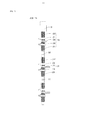
- FIG. 2 is a schematic structural diagram of an automatic electrode clamping system according to an embodiment of the present invention.
- Electrode automatic clamping device 100 Motor 10 Clamping assembly 20 First lead screw twenty two Upper plate twenty four Electrode holder 26 Lower plate 28 Second lead screw 29 Connector 32 Electrode automatic clamping system 200
- an embodiment of the present invention provides an automatic electrode clamping device 100 .
- the electrode automatic clamping device 100 includes a motor 10 and a clamping assembly 20 .
- the motor 10 includes a rotating shaft
- the clamping assembly 20 includes a first lead screw 22, an upper pressing plate 24, an electrode holder 26, a lower pressing plate 28, and a second lead screw 29, wherein the first lead screw 22 and the second lead screw 29 have oppositely-threaded threads.
- the first lead screw 22 has opposite first and second ends in a length extension direction, the first end is fixedly connected to a rotating shaft of the motor, and the second end is opposite to the second lead screw 29 Fixedly connected, the upper pressing plate 24 is connected to the first lead screw 22 by a screw pair, the lower pressing plate 28 is connected to the second lead screw 29 by a screw pair, and the electrode holder 26 is disposed on the upper pressing plate Between the 24 and the lower pressing plate 28, the rotating shaft of the motor 10 rotates forward and backward, and the upper pressing plate 24 and the lower pressing plate 28 are brought closer to or away from each other to realize clamping and loosening of the electrode holder 26.
- the motor 10 drives the first lead screw 22 and the second lead screw 29 to rotate by the rotating shaft.
- the first lead screw 22 and the second lead screw 29 have opposite threading directions, such as one of which may be a left-handed screw and the other of which is a right-handed screw.
- the first lead screw 22 is a left-handed screw
- the second lead screw 29 is a right-handed screw.
- the screwing of the oppositely directed screw causes the motor 10 to rotate the upper platen 24 and the lower platen 28 in opposite or opposite directions during rotation, thereby achieving automatic clamping and loosening of the electrode holder.
- the second lead screw 29 also has opposite first and second ends in the length extension direction, and the first lead screw 22 and the second lead screw 29 are connected end to end in the length extension direction. That is, the first lead screw 22 and the second lead screw 29 are connected in series.
- the first lead screw 22 may be integrally connected to the second lead screw 29 or connected by a connecting member.
- the upper platen 24 has a threaded hole that cooperates with a thread on the surface of the first lead screw 22.
- the lower platen 28 has a threaded bore that mates with the surface of the second lead screw 29. Since the electrode automatic clamping device 100 is assembled on the mounting panel of the battery forming device in use, the degree of freedom of rotation of the upper pressing plate 24 and the lower pressing plate 28 is limited (ie, does not surround the first lead screw) 22 or the second lead screw 29 performs a rotary motion), so that when the first lead screw 22 and the second lead screw 29 rotate, the upper pressing plate 24 and the lower pressing plate 28 may be along the first lead screw 22 Or the linear motion of the second lead screw 29 in the direction in which the length extends is opposite or opposite.
- the electrode holder 26 is used to clamp or loosen the electrodes of the battery.
- the electrode holder 26 can adopt a conventional clip structure.
- the electrode holder 26 includes an elastic device that allows the electrode holder 26 to be in a normally closed state under unstressed conditions.
- the working process of the automatic electrode clamping device 100 is as follows.
- the rotating shaft of the motor 10 rotates in the forward and reverse directions, the first screw 22 and the second screw 29 can be rotated to cause the upper pressing plate 24 and the lower portion.
- the platen 28 is brought close and away to effect clamping and loosening of the electrode holder 26.
- an embodiment of the present invention further provides an electrode automatic clamping system 200 including the motor 10 and a plurality of the clamping assemblies 20, the plurality of clamping assemblies 20 Connected in series, the motor 10 drives the first lead screw 22 and the second lead screw 29 of the plurality of clamping assemblies 20 to rotate, so that the electrode holders 26 in each clamping assembly 20 are clamped and loosened, thereby Automatic operation of multiple batteries is possible.
- the plurality of clamping assemblies 20 can be connected in series and fixedly by the connecting member 32 to enable the motor 10 to drive the plurality of clamping assemblies 20 to work simultaneously.
- the automatic electrode clamping device 100 provided by the embodiment of the present invention rotates the first lead screw 22 and the second lead screw 29 by the rotation of the motor 10, so that the upper pressing plate 24 and the lower pressing plate 28 are close to or away from each other, thereby realizing the electrode holder 26 Clamping and loosening, the purpose of automatic control electrode clamping is achieved. Furthermore, since the electrode automatic clamping system 200 includes a plurality of the series of clamping assemblies 20, simultaneous automatic control of the plurality of electrode holders 26 can be achieved by the motor 10.
Landscapes
- Engineering & Computer Science (AREA)
- Manufacturing & Machinery (AREA)
- Chemical & Material Sciences (AREA)
- Chemical Kinetics & Catalysis (AREA)
- Electrochemistry (AREA)
- General Chemical & Material Sciences (AREA)
- Battery Electrode And Active Subsutance (AREA)
- Jigs For Machine Tools (AREA)
Abstract
本发明涉及一种电极自动夹紧装置,包括一电机以及一夹紧组件,所述电机包括一转轴,所述夹紧组件包括第一丝杠、上压板、电极夹、下压板以及第二丝杠,其中,所述第一丝杠与所述第二丝杠具有旋向相反的螺纹,所述第一丝杠在长度延伸方向上具有相对的第一端和第二端,所述第一端与所述电机的转轴固定连接,所述第二端与所述第二丝杠固定连接,所述上压板通过螺旋副连接于所述第一丝杠,所述下压板通过螺旋副连接于所述第二丝杠,所述电极夹设置在所述上压板和所述下压板之间,所述电机的转轴正反转动,带动所述上压板和下压板相互靠近或远离,来实现所述电极夹的夹紧和松开。本发明还涉及一种电极自动夹紧系统。
Description
本发明涉及一种自动夹紧装置以及电极自动夹紧系统,尤其涉及一种用于锂离子电池化成的电极自动夹紧装置以及电极自动夹紧系统。
锂离子电池整个化成流程一般需要10-15天,电池要进行多次阶段性的充放电,多次充放电之间电池必须从充放电柜上卸下来放到另一处静置,因此电池的电极要被多次的夹住和松开。目前锂离子电池化成流程中的设备基本为手工操作类型的设备,生产效率低,严重制约了电池产量的上升。
有鉴于此,确有必要提供一种能够在锂离子电池化成过程自动夹紧电极的电极夹紧装置以及电极自动夹紧系统。
一种电极自动夹紧装置,包括一电机以及一夹紧组件,所述电机包括一转轴,所述夹紧组件包括第一丝杠、上压板、电极夹、下压板以及第二丝杠,其中,所述第一丝杠与所述第二丝杠具有旋向相反的螺纹,所述第一丝杠在长度延伸方向上具有相对的第一端和第二端,所述第一端与所述电机的转轴固定连接,所述第二端与所述第二丝杠固定连接,所述上压板通过螺旋副连接于所述第一丝杠,所述下压板通过螺旋副连接于所述第二丝杠,所述电极夹设置在所述上压板和所述下压板之间,所述电机的转轴正反转动,带动所述上压板和下压板相互靠近或远离,来实现所述电极夹的夹紧和松开。
一种电极自动夹紧系统,包括所述电机以及多个相互串联的所述夹紧组件,所述电机带动该多个夹紧组件工作,以使每个所述夹紧组件中的电极夹自动夹紧和松开。
与现有技术相比较,本发明实施例提供的电极自动夹紧装置通过电机转动带动所述第一丝杠及第二丝杠转动,使得上压板与下压板靠近或远离,进而实现了电极夹的夹紧与松开,达到自动控制电极夹紧的目的。此外,由于所述电极自动夹紧装置包括多个所述串联的夹紧组件,从而可通过所述电机带动实现多个电极夹的同时自动控制。
图1为本发明实施例提供的电极自动夹紧装置的结构示意图。
图2为本发明实施例提供的电极自动夹紧系统的结构示意图。
| 电极自动夹紧装置 | 100 |
| 电机 | 10 |
| 夹紧组件 | 20 |
| 第一丝杠 | 22 |
| 上压板 | 24 |
| 电极夹 | 26 |
| 下压板 | 28 |
| 第二丝杠 | 29 |
| 连接件 | 32 |
| 电极自动夹紧系统 | 200 |
如下具体实施方式将结合上述附图进一步说明本发明。
以下将结合附图详细说明本发明实施例提供的电极自动夹紧装置以及电极自动夹紧系统。
请参阅图1,本发明实施例提供一种电极自动夹紧装置100,该电极自动夹紧装置100包括一电机10以及一夹紧组件20,所述电机10包括一转轴,所述夹紧组件20包括第一丝杠22、上压板24、电极夹26、下压板28以及第二丝杠29,其中,所述第一丝杠22与所述第二丝杠29具有旋向相反的螺纹,所述第一丝杠22在长度延伸方向上具有相对的第一端和第二端,所述第一端与所述电机的转轴固定连接,所述第二端与所述第二丝杠29固定连接,所述上压板24通过螺旋副连接于所述第一丝杠22,所述下压板28通过螺旋副连接于所述第二丝杠29,所述电极夹26设置在所述上压板24和所述下压板28之间,所述电机10的转轴正反转动,带动所述上压板24和下压板28相互靠近或远离,来实现所述电极夹26的夹紧和松开。
所述电机10通过所述转轴带动所述第一丝杠22和第二丝杠29转动。
所述第一丝杠22与第二丝杠29具有相反的螺纹旋向,如其中一个可以为左旋丝杠,另外一个为右旋丝杠。本发明实施例中,所述第一丝杠22为左旋丝杠,所述第二丝杠29为右旋丝杠。采用螺纹旋向相反的丝杠可使所述电机10在转动时,带动所述上压板24和下压板28相向或背向运动,从而实现所述电极夹的自动夹紧和松开。所述第二丝杠29同样在长度延伸方向上具有相对的第一端和第二端,所述第一丝杠22与所述第二丝杠29在长度延伸方向上通过端对端连接,即所述第一丝杠22和所述第二丝杠29串联连接。所述第一丝杠22可与所述第二丝杠29一体连接或通过连接件连接。
所述上压板24具有一螺纹孔,该螺纹孔与所述第一丝杠22表面的螺纹相互配合。同样地,所述下压板28具有与所述第二丝杠29表面螺纹相互配合的螺纹孔。由于该电极自动夹紧装置100在使用时装配于电池化成装置的装配面板上,从而所述上压板24与所述下压板28的转动自由度受限(即不会绕所述第一丝杠22或第二丝杠29做旋转运动),从而在所述第一丝杠22和第二丝杠29转动时,所述上压板24和所述下压板28可以沿所述第一丝杠22或第二丝杠29长度延伸方向上做相向或相背的直线运动。
所述电极夹26用于夹紧或松开所述电池的电极。该电极夹26可采用习知的夹子结构。本发明实施例中,所述电极夹26包括弹性装置,该弹性装置可使该电极夹26在不受力的条件下处于常闭状态。
该电极自动夹紧装置100的工作过程如下,所述电机10的转轴正反转动时,可带动所述第一丝杠22和第二丝杠29转动,致使所述上压板24与所述下压板28靠近和远离,从而实现所述电极夹26的夹紧和松开。
请参阅图2,本发明实施例进一步提供了一种电极自动夹紧系统200,该电极自动夹紧系统200包括所述电机10以及多个所述夹紧组件20,该多个夹紧组件20串联连接,所述电机10带动该多个夹紧组件20的第一丝杠22和第二丝杠29转动,以使每个夹紧组件20中的电极夹26实现夹紧和松开,从而可实现对多个电池的自动操作。
所述多个夹紧组件20之间可通过连接件32来串联且固定连接,以使所述电机10带动该多个夹紧组件20同时工作。
本发明实施例提供的电极自动夹紧装置100通过电机10转动带动所述第一丝杠22及第二丝杠29转动,使得上压板24与下压板28靠近或远离,进而实现了电极夹26的夹紧与松开,达到自动控制电极夹紧的目的。此外,由于所述电极自动夹紧系统200包括多个所述串联的夹紧组件20,从而可通过所述电机10带动实现多个电极夹26的同时自动控制。
另外,本领域技术人员还可以在本发明精神内做其它变化,当然,这些依据本发明精神所做的变化,都应包含在本发明所要求保护的范围之内。
Claims (5)
- 一种电极自动夹紧装置,其特征在于,包括一电机以及一夹紧组件,所述电机包括一转轴,所述夹紧组件包括第一丝杠、上压板、电极夹、下压板以及第二丝杠,其中,所述第一丝杠与所述第二丝杠具有旋向相反的螺纹,所述第一丝杠在长度延伸方向上具有相对的第一端和第二端,所述第一端与所述电机的转轴固定连接,所述第二端与所述第二丝杠固定连接,所述上压板通过螺旋副连接于所述第一丝杠,所述下压板通过螺旋副连接于所述第二丝杠,所述电极夹设置在所述上压板和所述下压板之间,所述电机的转轴正反转动,带动所述上压板和下压板相互靠近或远离,来实现所述电极夹的夹紧和松开。
- 如权利要求1所述的电极自动夹紧装置,其特征在于,所述第一丝杠和第二丝杠一体连接。
- 如权利要求1所述的电极自动夹紧装置,其特征在于,所述第一丝杠为左旋丝杠,第二丝杠为右旋丝杠。
- 一种电极自动夹紧系统,其特征在于,包括如权利要求1-3中任意一项所述的电机以及多个相互串联的所述夹紧组件,所述电机带动该多个夹紧组件工作,以使每个所述夹紧组件中的电极夹自动夹紧和松开。
- 如权利要求4所述的电极自动夹紧系统,其特征在于,所述多个夹紧组件之间通过连接件固定连接。
Applications Claiming Priority (2)
| Application Number | Priority Date | Filing Date | Title |
|---|---|---|---|
| CN201410351960.2A CN104241692B (zh) | 2014-07-23 | 2014-07-23 | 电极自动夹紧装置以及电极自动夹紧系统 |
| CN201410351960.2 | 2014-07-23 |
Publications (1)
| Publication Number | Publication Date |
|---|---|
| WO2016011858A1 true WO2016011858A1 (zh) | 2016-01-28 |
Family
ID=52229354
Family Applications (1)
| Application Number | Title | Priority Date | Filing Date |
|---|---|---|---|
| PCT/CN2015/081513 Ceased WO2016011858A1 (zh) | 2014-07-23 | 2015-06-16 | 电极自动夹紧装置以及电极自动夹紧系统 |
Country Status (2)
| Country | Link |
|---|---|
| CN (1) | CN104241692B (zh) |
| WO (1) | WO2016011858A1 (zh) |
Families Citing this family (4)
| Publication number | Priority date | Publication date | Assignee | Title |
|---|---|---|---|---|
| CN104241692B (zh) * | 2014-07-23 | 2017-04-19 | 江苏华东锂电技术研究院有限公司 | 电极自动夹紧装置以及电极自动夹紧系统 |
| CN107741472B (zh) * | 2017-11-09 | 2024-04-12 | 郑州云海信息技术有限公司 | 一种防止服务器湿度过标监测装置 |
| CN108714736A (zh) * | 2018-06-21 | 2018-10-30 | 浙江豪精机电有限公司 | 一种高精度点焊机 |
| CN111350922A (zh) * | 2018-12-24 | 2020-06-30 | 中国空气动力研究与发展中心超高速空气动力研究所 | 一种大行程高负载的倾斜角度调整装置 |
Citations (5)
| Publication number | Priority date | Publication date | Assignee | Title |
|---|---|---|---|---|
| JPH08100385A (ja) * | 1994-09-30 | 1996-04-16 | Mitsubishi Heavy Ind Ltd | スライスリップ微調整装置 |
| CN201711885U (zh) * | 2010-07-16 | 2011-01-19 | 国核电站运行服务技术有限公司 | 一种圆柱体自动定心夹紧装置 |
| CN201970107U (zh) * | 2010-11-29 | 2011-09-14 | 广西玉柴重工有限公司 | 翻转夹紧装置 |
| CN204011574U (zh) * | 2014-07-23 | 2014-12-10 | 江苏华东锂电技术研究院有限公司 | 电极自动夹紧装置以及电极自动夹紧系统 |
| CN104241692A (zh) * | 2014-07-23 | 2014-12-24 | 江苏华东锂电技术研究院有限公司 | 电极自动夹紧装置以及电极自动夹紧系统 |
Family Cites Families (3)
| Publication number | Priority date | Publication date | Assignee | Title |
|---|---|---|---|---|
| CN101758468A (zh) * | 2008-10-31 | 2010-06-30 | 吴江市菀坪旭日缝纫机零件厂 | 丝杆夹紧装置 |
| CN102373524A (zh) * | 2010-08-11 | 2012-03-14 | 江苏康非特动力科技有限公司 | 一种纤维绳锁紧机构 |
| CN202264020U (zh) * | 2011-10-20 | 2012-06-06 | 成都艾格科技有限责任公司 | 一种移动式钢轨闪光焊机的钢轨内侧作用边对中装置 |
-
2014
- 2014-07-23 CN CN201410351960.2A patent/CN104241692B/zh active Active
-
2015
- 2015-06-16 WO PCT/CN2015/081513 patent/WO2016011858A1/zh not_active Ceased
Patent Citations (5)
| Publication number | Priority date | Publication date | Assignee | Title |
|---|---|---|---|---|
| JPH08100385A (ja) * | 1994-09-30 | 1996-04-16 | Mitsubishi Heavy Ind Ltd | スライスリップ微調整装置 |
| CN201711885U (zh) * | 2010-07-16 | 2011-01-19 | 国核电站运行服务技术有限公司 | 一种圆柱体自动定心夹紧装置 |
| CN201970107U (zh) * | 2010-11-29 | 2011-09-14 | 广西玉柴重工有限公司 | 翻转夹紧装置 |
| CN204011574U (zh) * | 2014-07-23 | 2014-12-10 | 江苏华东锂电技术研究院有限公司 | 电极自动夹紧装置以及电极自动夹紧系统 |
| CN104241692A (zh) * | 2014-07-23 | 2014-12-24 | 江苏华东锂电技术研究院有限公司 | 电极自动夹紧装置以及电极自动夹紧系统 |
Also Published As
| Publication number | Publication date |
|---|---|
| CN104241692B (zh) | 2017-04-19 |
| CN104241692A (zh) | 2014-12-24 |
Similar Documents
| Publication | Publication Date | Title |
|---|---|---|
| WO2016011858A1 (zh) | 电极自动夹紧装置以及电极自动夹紧系统 | |
| CN104655484B (zh) | 一种用于通电拉伸的夹具 | |
| CN103433930A (zh) | 一种可更换夹持爪的舵机齿轮式夹持器 | |
| CN103728474A (zh) | 高空接线钳 | |
| CN105917858A (zh) | 一种旋转式水果采摘机械手 | |
| CN106078270A (zh) | 一种电器配件加工用钻孔机 | |
| CN204011574U (zh) | 电极自动夹紧装置以及电极自动夹紧系统 | |
| CN104362549A (zh) | 一种可双线同时拉紧的紧线器 | |
| CN203697636U (zh) | 高端摄像模组fpc贴片固定治具 | |
| CN203895839U (zh) | 带电引流并沟线夹螺栓紧固器 | |
| CN218158256U (zh) | 一种用于电池外部短路测试夹具 | |
| CN205166948U (zh) | 一种机械手夹具及机械手 | |
| CN205996583U (zh) | 一种电器配件加工用钻孔机 | |
| CN111438511B (zh) | 一种高安全性的适用于带电作业机器人的穿刺线夹拧紧装置 | |
| CN102790299B (zh) | 一种适合锂电池化成自动化生产线的平板式电极夹具 | |
| CN207240102U (zh) | 便携式接线板螺栓安装辅助装置 | |
| CN205262617U (zh) | 一种固定装置 | |
| CN203481727U (zh) | 一种快卸式电缆卡箍 | |
| CN210826420U (zh) | 一种活动扳手的电镀夹持装置 | |
| CN205254126U (zh) | 取换料装置 | |
| CN213291331U (zh) | 一种pvc管攻丝装置 | |
| CN210879707U (zh) | 一种可调节摩擦力的机器人用夹爪 | |
| CN209501374U (zh) | 一种便于伸缩快速安装滤芯的装置 | |
| CN204239417U (zh) | 一种铜双头螺柱 | |
| CN222819109U (zh) | 一种快拆型pcb钻孔机钻头 |
Legal Events
| Date | Code | Title | Description |
|---|---|---|---|
| 121 | Ep: the epo has been informed by wipo that ep was designated in this application |
Ref document number: 15825361 Country of ref document: EP Kind code of ref document: A1 |
|
| NENP | Non-entry into the national phase |
Ref country code: DE |
|
| 122 | Ep: pct application non-entry in european phase |
Ref document number: 15825361 Country of ref document: EP Kind code of ref document: A1 |